

Page 1

Cat. No. I546-E1-02
0675398-6B
SETUP MANUAL
SYSDRIVE 3G3JV
Compact Simplified Inverters
Page 2

Thank you for choosing this SYSDRIVE 3G3JV-series product. Proper use
and handling of the product will ensure proper product performance, will
lengthen product life, and may prevent possible accidents.
Please read this manual thoroughly and handle and operate the product
with care.
1. To ensure safe and proper use of the OMRON Inverters, please read this SETUP
MANUAL and the USER’S MANUAL (Cat. No. I528-E1) to gain sufficient knowledge
of the devices, safety information, and precautions before actual use.
2. The products are illustrated without covers and shieldings for closer look in this SETUP MANUAL and the USER’S MANUAL. For actual use of the products, make sure to
use the covers and shieldings as specified.
3. This SETUP MANUAL and other related user’s manuals are to be delivered to the actual end users of the products.
4. Please keep this manual close at hand for future reference.
5. If the product has been left unused for a long time, please inquire at our sales representative.
NOTICE
1. This manual describes the functions of the product and relations with other
products. You should assume that anything not described in this manual is
not possible.
2. Although care has been given in documenting the product, please contact your
OMRON representative if you have any suggestions on improving this manual.
3. The product contains potentially dangerous parts under the cover. Do not attempt
to open the cover under any circumstances. Doing so may result in injury or death
and may damage the product. Never attempt to repair or disassemble the product.
4. We recommend that you add the following precautions to any instruction manuals
you prepare for the system into which the product is being installed.
S Precautions on the dangers of high-voltage equipment.
S Precautions on touching the terminals of the product even after power has been
turned OFF. (These terminals are live even with the power turned OFF.)
5. Specifications and functions may be changed without notice in order to improve
product performance.
Items to Check Before Unpacking
Check the following items before removing the product from the package:
S Has the correct product been delivered (i.e., the correct model number and speci-
fications)?
S Has the product been damaged in shipping?
S Are any screws or bolts loose?
Page 3

Notice:
OMRON products are manufactured for use according to proper procedures by a qualified
operator and only for the purposes described in this manual.
The following conventions are used to indicate and classify precautions in this manual. Always heed the information provided with them. Failure to heed precautions can result in injury to people or damage to property.
!
DANGER Indicates an imminently hazardous situation which, if not avoided, will result in death
or serious injury. Additionally, there may be severe property damage.
WARNING Indicates a potentially hazardous situation which, if not avoided, could result in death
!
or serious injury. Additionally, there may be severe property damage.
Caution Indicates a potentially hazardous situation which, if not avoided, may result in minor
!
or moderate injury, or property damage.
OMRON Product References
All OMRON products are capitalized in this manual. The word “Unit” is also capitalized when
it refers to an OMRON product, regardless of whether or not it appears in the proper name
of the product.
The abbreviation “Ch,” which appears in some displays and on some OMRON products,
often means “word” and is abbreviated “Wd” in documentation in this sense.
The abbreviation “PC” means Programmable Controller and is not used as an abbreviation
for anything else.
Visual Aids
The following headings appear in the left column of the manual to help you locate different
types of information.
Note Indicates information of particular interest for efficient and convenient operation of the product.
OMRON, 2005
All rights reserved. No part of this publication may be reproduced, stored in a retrieval system, or transmitted,
in any form, or by any means, mechanical, electronic, photocopying, recording, or otherwise, without the prior
written permission of OMRON.
No patent liability is assumed with respect to the use of the information contained herein. Moreover, because
OMRON is constantly striving to improve its high-quality products, the information contained in this manual
is subject to change without notice. Every precaution has been taken in the preparation of this manual. Nevertheless, OMRON assumes no responsibility for errors or omissions. Neither is any liability assumed for damages resulting from the use of the information contained in this publication.
Page 4
Read and Understand this Manual
Á
Á
Á
Á
Á
Á
Á
Á
Á
Á
Á
Á
Á
Á
Á
Please read and understand this manual before using the product. Please consult your OMRON
representative if you have any questions or comments.
Warranty and Limitations of Liability
WARRANTY
OMRON’s exclusive warranty is that the products are free from defects in materials and workmanship for
БББББББББББББББББББББББББББББББ
a period of one year (or other period if specified) from date of sale by OMRON.
БББББББББББББББББББББББББББББББ
БББББББББББББББББББББББББББББББ
OMRON MAKES NO WARRANTY OR REPRESENTATION, EXPRESS OR IMPLIED, REGARDING
NON-INFRINGEMENT, MERCHANTABILITY, OR FITNESS FOR PARTICULAR PURPOSE OF THE
БББББББББББББББББББББББББББББББ
PRODUCTS. ANY BUYER OR USER ACKNOWLEDGES THAT THE BUYER OR USER ALONE HAS
БББББББББББББББББББББББББББББББ
DETERMINED THAT THE PRODUCTS WILL SUITABLY MEET THE REQUIREMENTS OF THEIR
БББББББББББББББББББББББББББББББ
INTENDED USE. OMRON DISCLAIMS ALL OTHER WARRANTIES, EXPRESS OR IMPLIED.
БББББББББББББББББББББББББББББББ
LIMITATIONS OF LIABILITY
OMRON SHALL NOT BE RESPONSIBLE FOR SPECIAL, INDIRECT, OR CONSEQUENTIAL
DAMAGES, LOSS OF PROFITS OR COMMERCIAL LOSS IN ANY WAY CONNECTED WITH THE
БББББББББББББББББББББББББББББББ
PRODUCTS, WHETHER SUCH CLAIM IS BASED ON CONTRACT, WARRANTY, NEGLIGENCE, OR
БББББББББББББББББББББББББББББББ
STRICT LIABILITY.
БББББББББББББББББББББББББББББББ
In no event shall the responsibility of OMRON for any act exceed the individual price of the product on
БББББББББББББББББББББББББББББББ
which liability is asserted.
БББББББББББББББББББББББББББББББ
БББББББББББББББББББББББББББББББ
IN NO EVENT SHALL OMRON BE RESPONSIBLE FOR WARRANTY, REPAIR, OR OTHER CLAIMS
REGARDING THE PRODUCTS UNLESS OMRON’S ANALYSIS CONFIRMS THAT THE PRODUCTS
БББББББББББББББББББББББББББББББ
WERE PROPERLY HANDLED, STORED, INSTALLED, AND MAINTAINED AND NOT SUBJECT TO
БББББББББББББББББББББББББББББББ
CONTAMINATION, ABUSE, MISUSE, OR INAPPROPRIATE MODIFICATION OR REPAIR.
Page 5
Application Considerations
Á
Á
Á
Á
Á
Á
Á
Á
Á
Á
Á
Á
Á
Á
Á
Á
Á
Á
Á
Á
Á
БББББББББББББББББББББББББББББББ
SUITABILITY FOR USE
OMRON shall not be responsible for conformity with any standards, codes, or regulations that apply to
the combination of products in the customer’s application or use of the products.
БББББББББББББББББББББББББББББББ
БББББББББББББББББББББББББББББББ
At the customer’s request, OMRON will provide applicable third party certification documents identifying
ratings and limitations of use that apply to the products. This information by itself is not sufficient for a
БББББББББББББББББББББББББББББББ
complete determination of the suitability of the products in combination with the end product, machine,
БББББББББББББББББББББББББББББББ
system, or other application or use.
БББББББББББББББББББББББББББББББ
БББББББББББББББББББББББББББББББ
The following are some examples of applications for which particular attention must be given. This is not
intended to be an exhaustive list of all possible uses of the products, nor is it intended to imply that the
БББББББББББББББББББББББББББББББ
uses listed may be suitable for the products:
БББББББББББББББББББББББББББББББ
• Outdoor use, uses involving potential chemical contamination or electrical interference, or conditions
БББББББББББББББББББББББББББББББ
or uses not described in this manual.
БББББББББББББББББББББББББББББББ
• Nuclear energy control systems, combustion systems, railroad systems, aviation systems, medical
БББББББББББББББББББББББББББББББ
equipment, amusement machines, vehicles, safety equipment, and installations subject to separate
БББББББББББББББББББББББББББББББ
industry or government regulations.
БББББББББББББББББББББББББББББББ
• Systems, machines, and equipment that could present a risk to life or property.
БББББББББББББББББББББББББББББББ
Please know and observe all prohibitions of use applicable to the products.
БББББББББББББББББББББББББББББББ
БББББББББББББББББББББББББББББББ
NEVER USE THE PRODUCTS FOR AN APPLICATION INVOLVING SERIOUS RISK TO LIFE OR
БББББББББББББББББББББББББББББББ
PROPERTY WITHOUT ENSURING THAT THE SYSTEM AS A WHOLE HAS BEEN DESIGNED TO
ADDRESS THE RISKS, AND THAT THE OMRON PRODUCTS ARE PROPERLY RATED AND
БББББББББББББББББББББББББББББББ
INSTALLED FOR THE INTENDED USE WITHIN THE OVERALL EQUIPMENT OR SYSTEM.
БББББББББББББББББББББББББББББББ
PROGRAMMABLE PRODUCTS
OMRON shall not be responsible for the user’s programming of a programmable product, or any
БББББББББББББББББББББББББББББББ
consequence thereof.
Page 6
Disclaimers
Á
Á
Á
Á
Á
Á
Á
Á
Á
Á
Á
Á
Á
БББББББББББББББББББББББББББББББ
CHANGE IN SPECIFICATIONS
Product specifications and accessories may be changed at any time based on improvements and other
reasons.
БББББББББББББББББББББББББББББББ
БББББББББББББББББББББББББББББББ
It is our practice to change model numbers when published ratings or features are changed, or when
БББББББББББББББББББББББББББББББ
significant construction changes are made. However, some specifications of the products may be
changed without any notice. When in doubt, special model numbers may be assigned to fix or establish
БББББББББББББББББББББББББББББББ
key specifications for your application on your request. Please consult with your OMRON representative
БББББББББББББББББББББББББББББББ
at any time to confirm actual specifications of purchased products.
БББББББББББББББББББББББББББББББ
DIMENSIONS AND WEIGHTS
Dimensions and weights are nominal and are not to be used for manufacturing purposes, even when
БББББББББББББББББББББББББББББББ
tolerances are shown.
БББББББББББББББББББББББББББББББ
PERFORMANCE DATA
Performance data given in this manual is provided as a guide for the user in determining suitability and
does not constitute a warranty. It may represent the result of OMRON’s test conditions, and the users
БББББББББББББББББББББББББББББББ
must correlate it to actual application requirements. Actual performance is subject to the OMRON
БББББББББББББББББББББББББББББББ
Warranty and Limitations of Liability.
БББББББББББББББББББББББББББББББ
ERRORS AND OMISSIONS
The information in this manual has been carefully checked and is believed to be accurate; however, no
responsibility is assumed for clerical, typographical, or proofreading errors, or omissions.
БББББББББББББББББББББББББББББББ
Page 7

General Precautions
Observe the following precautions when using the SYSDRIVE Inverters and peripheral devices.
This manual may include illustrations of the product with protective covers removed in order
to describe the components of the product in detail. Make sure that these protective covers
are on the product before use.
Consult your OMRON representative when using the product after a long period of storage.
WARNING Do not touch the inside of the Inverter. Doing so may result in electrical shock.
!
WARNING Operation, maintenance, or inspection must be performed after turning OFF the
!
power supply, confirming that the CHARGE indicator (or status indicators) are OFF,
and after waiting for the time specified on the front cover. Not doing so may result in
electrical shock.
WARNING Do not damage, pull on, apply stress to, place heavy objects on, or pinch the cables.
!
Doing so may result in electrical shock.
WARNING Do not touch the rotating parts of the motor under operation. Doing so may result in
!
injury.
WARNING Do not modify the product. Doing so may result in injury or damage to the product.
!
Caution Do not store, install, or operate the product in the following places. Doing so may
!
result in electrical shock, fire or damage to the product.
S Locations subject to direct sunlight.
S Locations subject to temperatures or humidity outside the range specified in the
specifications.
S Locations subject to condensation as the result of severe changes in temperature.
S Locations subject to corrosive or flammable gases.
S Locations subject to exposure to combustibles.
S Locations subject to dust (especially iron dust) or salts.
S Locations subject to exposure to water, oil, or chemicals.
S Locations subject to shock or vibration.
Caution Do not touch the Inverter radiator, regenerative resistor, or Servomotor while the
!
power is being supplied or soon after the power is turned OFF. Doing so may result in
a skin burn due to the hot surface.
Caution Do not conduct a dielectric strength test on any part of the Inverter. Doing so may
!
result in damage to the product or malfunction.
Caution Take appropriate and sufficient countermeasures when installing systems in the fol-
!
lowing locations. Not doing so may result in equipment damage.
S Locations subject to static electricity or other forms of noise.
S Locations subject to strong electromagnetic fields and magnetic fields.
S Locations subject to possible exposure to radioactivity.
S Locations close to power supplies.
Page 8

Transportation Precautions
Caution Do not hold by front cover or panel, instead, hold by the radiation fin (heat sink) while
!
transporting the product. Doing so may result in injury.
Caution Do not pull on the cables. Doing so may result in damage to the product or malfunc-
!
tion.
Caution Use the eye-bolts only for transporting the Inverter. Using them for transporting the
!
machinery may result in injury or malfunction.
Installation Precautions
WARNING Provide an appropriate stopping device on the machine side to secure safety. (A
!
holding brake is not a stopping device for securing safety.) Not doing so may result in
injury.
WARNING Provide an external emergency stopping device that allows an instantaneous stop of
!
operation and power interruption. Not doing so may result in injury.
Caution Be sure to install the product in the correct direction and provide specified clear-
!
ances between the Inverter and control panel or with other devices. Not doing so
may result in fire or malfunction.
Caution Do not allow foreign objects to enter inside the product. Doing so may result in fire or
!
malfunction.
Caution Do not apply any strong impact. Doing so may result in damage to the product or
!
malfunction.
Wiring Precautions
WARNING Wiring must be performed only after confirming that the power supply has been
!
turned OFF. Not doing so may result in electrical shock.
WARNING Wiring must be performed by authorized personnel. Not doing so may result in
!
electrical shock or fire.
WARNING Be sure to confirm operation only after wiring the emergency stop circuit. Not doing
!
so may result in injury.
WARNING Always connect the ground terminals to a ground of 100 Ω or less. Not connecting to
!
a proper ground may result in electrical shock.
Page 9

Caution Install external breakers and take other safety measures against short-circuiting in
!
external wiring. Not doing so may result in fire.
Caution Confirm that the rated input voltage of the Inverter is the same as the AC power sup-
!
ply voltage. An incorrect power supply may result in fire, injury, or malfunction.
Caution Connect the Braking Resistor and Braking Resistor Unit as specified in the manual.
!
Not doing so may result in fire.
Caution Be sure to wire correctly and securely. Not doing so may result in injury or damage to
!
the product.
Caution Be sure to firmly tighten the screws on the terminal block. Not doing so may result in
!
fire, injury, or damage to the product.
Caution Do not connect an AC power to the U, V, or W output. Doing so may result in damage
!
to the product or malfunction.
Caution Set the multi-function contact input parameter for NC contact terminals (e.g., 3-wire
!
sequence) before wiring them. If the parameter’s default setting is used, the motor
may start running when the input terminal S2 is turned ON.
Operation and Adjustment Precautions
WARNING Turn ON the input power supply only after mounting the front cover, terminal covers,
!
bottom cover, Operator, and optional items. Not doing so may result in electrical
shock.
WARNING Do not remove the front cover, terminal covers, bottom cover, Operator, or optional
!
items while the power is being supplied. Doing so may result in electrical shock or
damage to the product.
WARNING Do not operate the Operator or switches with wet hands. Doing so may result in
!
electrical shock.
WARNING Do not touch the inside of the Inverter. Doing so may result in electrical shock.
!
WARNING Do not come close to the machine when using the error retry function because the
!
machine may abruptly start when stopped by an alarm. Doing so may result in injury.
WARNING Do not come close to the machine immediately after resetting momentary power
!
interruption to avoid an unexpected restart (if operation is set to be continued in the
processing selection function after momentary power interruption is reset). Doing so
may result in injury.
Page 10

WARNING Provide a separate emergency stop switch because the STOP Key on the Operator
!
is valid only when function settings are performed. Not doing so may result in injury.
WARNING Be sure to confirm that the RUN signal is turned OFF before turning ON the power
!
supply, resetting the alarm, or switching the LOCAL/REMOTE selector. Doing so
while the RUN signal is turned ON may result in injury.
Caution Be sure to confirm permissible ranges of motors and machines before operation be-
!
cause the Inverter speed can be easily changed from low to high. Not doing so may
result in damage to the product.
Caution Provide a separate holding brake when necessary. Not doing so may result in injury.
!
Caution Do not perform a signal check during operation. Doing so may result in injury or dam-
!
age to the product.
Caution Do not carelessly change settings. Doing so may result in injury or damage to the
!
product.
Maintenance and Inspection Precautions
WARNING Do not touch the Inverter terminals while the power is being supplied.
!
WARNING Maintenance or inspection must be performed only after turning OFF the power
!
supply, confirming that the CHARGE indicator (or status indicators) is turned OFF,
and after waiting for the time specified on the front cover. Not doing so may result in
electrical shock.
WARNING Maintenance, inspection, or parts replacement must be performed by authorized
!
personnel. Not doing so may result in electrical shock or injury.
WARNING Do not attempt to take the Unit apart or repair. Doing either of these may result in
!
electrical shock or injury.
Caution Carefully handle the Inverter because it uses semiconductor elements. Careless
!
handling may result in malfunction.
Caution Do not change wiring, disconnect connectors, the Operator, or optional items, or re-
!
place fans while power is being supplied. Doing so may result in injury, damage to
the product, or malfunction.
Page 11

Warnings for UL/cUL Marking
• Do not connect or disconnect wiring, or perform signal checks while the power supply is turned ON.
• The Inverter internal capacitor is still charged even after the power supply is turned OFF. To prevent
electrical shock, disconnect all power before servicing the Inverter. Then wait at least one minute after
the power supply is disconnected and all indicators are OFF.
• Do not perform a withstand voltage test on any part of the Inverter. This electronic equipment uses
semiconductors and is vulnerable to high voltage.
• Do not remove the Digital Operator or the blank cover unless the power supply is turned OFF. Never
touch the printed control board (PCB) while the power supply is turned ON.
• The Inverter is not suitable for use on a circuit capable of delivering more than 5,000 RMS symmetrical
amperes, 250 volts maximum (100-V-class Units).
• Take measures against overcurrent, overload, and overheating by using the Motor Protection Settings.
CAUTION
Use 75°C copper wires or equivalent.
Low voltage wires shall be wired with Class I Wiring.
H Motor Protection Settings
Rated Motor Current (n32)
• Set the rated motor current (n32) in order to prevent the motor from burning due to overloading.
• Check the rated current on the motor nameplate and set the parameter.
• This parameter is used for the electronic thermal function for motor overload detection (OL1). By set-
ting the correct parameter, the overloaded motor will be protected from burning.
n32 Rated Motor Current Changes during
operation
Setting
range
0.0% to 120% (A) of rated
output current of Inverter
Unit of
setting
0.1 A Default setting (see note 1)
No
Note 1. The standard rated current of the maximum applicable motor is the default rated motor cur-
rent.
Note 2. Motor overload detection (OL1) is disabled by setting the parameter to 0.0.
Motor Protection Characteristics (n33 and n34)
• This parameters setting is for motor overload detection (OL1).
n33 Motor Protection Characteristic Selection Changes during
operation
Setting
range
0 to 2 Unit of
setting
1 Default setting 0
D Set Values
Value Description
0 Protection characteristics for general-purpose induction motors
1 Protection characteristics for Inverter-dedicated motors
2 No protection
No
Page 12

• This parameter is used to set the electric thermal characteristics of the motor to be connected.
• Set the parameter according to the motor.
• If a single Inverter is connected to more than one motor, set the parameter to 2 for no protection. The
parameter is also disabled by setting n32 for rated motor current to 0.0. Provide thermal relays or other
methods separately for each motor to protect equipment from overloads.
n34 Motor Protection Time Changes during
operation
Setting
range
1 to 60 (min) Unit of
setting
1 min Default setting 8
No
D Set Values
• This parameter is used to set the electronic thermal protection constant of motor overload detection
OL1.
• The default setting does not need any changes in normal operation.
• To set the parameter according to the characteristics of the motor, confirm the thermal time constant
with the motor manufacturer and set the parameter with some margin. In other words, set the value a
little shorter than the thermal time constant.
• To detect motor overloading more quickly, reduce the set value, provided that it does not cause any
application problems.
Page 13
Checking Before Unpacking
H Checking the Product
On delivery, always check that the delivered product is the SYSDRIVE 3G3JV Inverter that you ordered.
Should you find any problems with the product, immediately contact your nearest local sales
representative.
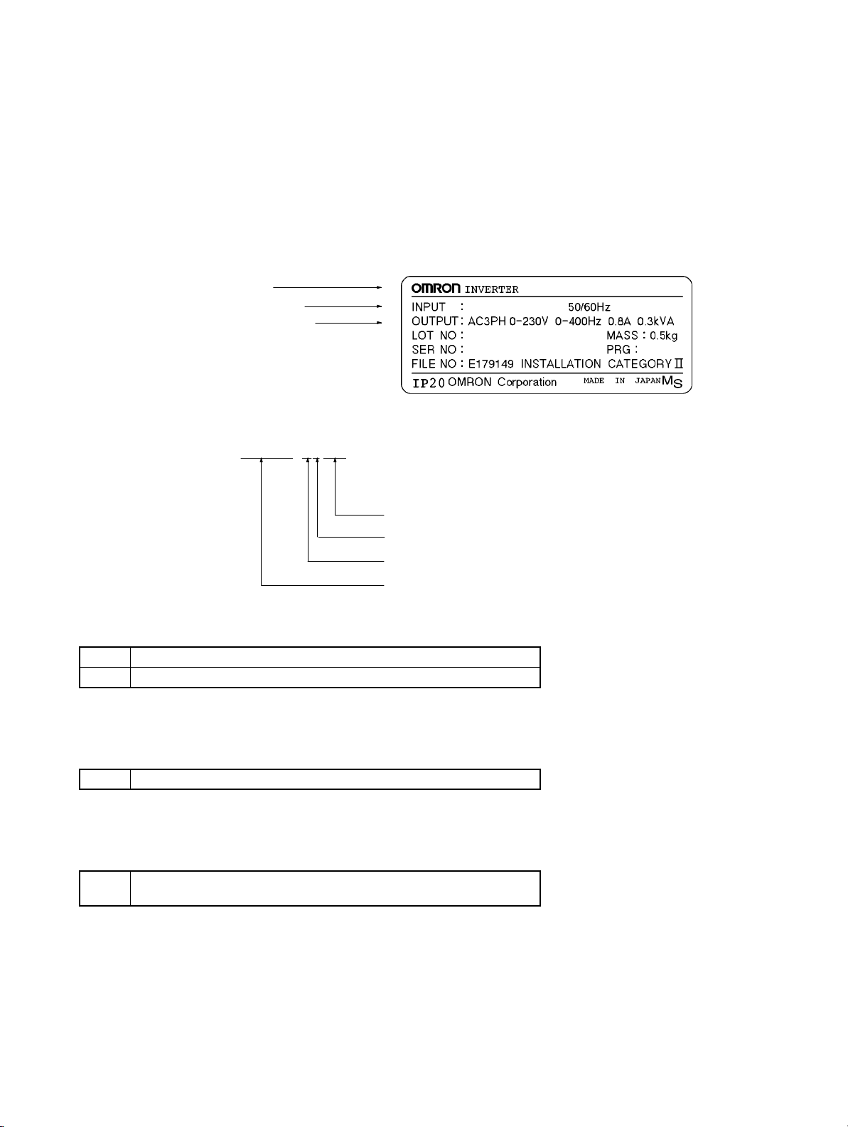
D Checking the Nameplate
Inverter model
Input specifications
Output specifications
D Checking the Model
3G3JV-A1001
Maximum applicable motor capacity
Voltage class
Installation type
Series name: 3G3JV Series
Maximum Applicable Motor Capacity
001 0.1 (0.1) kW
002 0.25/0.37 (0.2) kW
3G3JV-A1001
AC3PH 100-115V
3.2A
Note The figures in parentheses indicate capacities for motors used outside Japan.
Voltage Class
1 Single-phase 100-V AC input (100-V class)
Note The output is 3-phase 200 V AC.
Installation Type
A Panel-mounting models (IP10 min.) or
Closed wall mounting
D Checking for Damage
Check the overall appearance and check for damage or scratches resulting from transportation.
H Checking the Accessories
This manual is the only accessory provided with the 3G3JV. Set screws and other necessary parts must
be provided by the user.
Page 14

Table of Contents
Chapter 1. Design 1-1. . . . . . . . . . . . . . . . . . . . . . . . . . . . . . . . . . . . . . . . . .
1-1 Installation 1-2. . . . . . . . . . . . . . . . . . . . . . . . . . . . . . . . . . . . . . . . . . . . . . . . . . . . . . . . . . . . . . . . .
1-1-1 Dimensions 1-2. . . . . . . . . . . . . . . . . . . . . . . . . . . . . . . . . . . . . . . . . . . . . . . . . . . . . . . . . .
1-1-2 Removing and Mounting the Covers 1-4. . . . . . . . . . . . . . . . . . . . . . . . . . . . . . . . . . . . . .
1-2 Wiring 1-6. . . . . . . . . . . . . . . . . . . . . . . . . . . . . . . . . . . . . . . . . . . . . . . . . . . . . . . . . . . . . . . . . . . .
1-2-1 Terminal Block 1-6. . . . . . . . . . . . . . . . . . . . . . . . . . . . . . . . . . . . . . . . . . . . . . . . . . . . . . .
1-2-2 Standard Connections 1-10. . . . . . . . . . . . . . . . . . . . . . . . . . . . . . . . . . . . . . . . . . . . . . . . . .
1-2-3 Wiring around the Main Circuit 1-11. . . . . . . . . . . . . . . . . . . . . . . . . . . . . . . . . . . . . . . . . .
1-2-4 Optional Accessories 1-12. . . . . . . . . . . . . . . . . . . . . . . . . . . . . . . . . . . . . . . . . . . . . . . . . .
1-3 Specifications 1-13. . . . . . . . . . . . . . . . . . . . . . . . . . . . . . . . . . . . . . . . . . . . . . . . . . . . . . . . . . . . . . .
Chapter 2. Preparing for Operation and Monitoring 2-1. . . . . . . . . . . . .
2-1 Using the Digital Operator 2-2. . . . . . . . . . . . . . . . . . . . . . . . . . . . . . . . . . . . . . . . . . . . . . . . . . . .
2-1-1 Nomenclature 2-2. . . . . . . . . . . . . . . . . . . . . . . . . . . . . . . . . . . . . . . . . . . . . . . . . . . . . . . .
2-1-2 Accepting Operation Commands While Changing Parameters 2-4. . . . . . . . . . . . . . . . . .
2-1-3 Outline of Operation 2-5. . . . . . . . . . . . . . . . . . . . . . . . . . . . . . . . . . . . . . . . . . . . . . . . . . .
2-2 Copying and Verifying Parameters 2-7. . . . . . . . . . . . . . . . . . . . . . . . . . . . . . . . . . . . . . . . . . . . . .
2-2-1 Parameters Used to Copy and Verify Parameters 2-7. . . . . . . . . . . . . . . . . . . . . . . . . . . . .
2-2-2 Outline of Copying Parameters 2-9. . . . . . . . . . . . . . . . . . . . . . . . . . . . . . . . . . . . . . . . . .
2-2-3 Procedures 2-10. . . . . . . . . . . . . . . . . . . . . . . . . . . . . . . . . . . . . . . . . . . . . . . . . . . . . . . . . . .
2-2-4 Error Messages for Copying and Verifying Parameters 2-12. . . . . . . . . . . . . . . . . . . . . . . .
Chapter 3. List of Parameters 3-1. . . . . . . . . . . . . . . . . . . . . . . . . . . . . . . .
Chapter 4. Maintenance Operations 4-1. . . . . . . . . . . . . . . . . . . . . . . . . . .
4-1 Protective and Diagnostic Functions 4-2. . . . . . . . . . . . . . . . . . . . . . . . . . . . . . . . . . . . . . . . . . . . .
4-1-1 Fault Detection (Fatal Error) 4-2. . . . . . . . . . . . . . . . . . . . . . . . . . . . . . . . . . . . . . . . . . . .
4-1-2 Warning Detection (Nonfatal Error) 4-7. . . . . . . . . . . . . . . . . . . . . . . . . . . . . . . . . . . . . . .
4-2 Inspection and Maintenance 4-10. . . . . . . . . . . . . . . . . . . . . . . . . . . . . . . . . . . . . . . . . . . . . . . . . . .
Page 15

Design
1-1 Installation
1-2 Wiring
1-3 Specifications
1
Chapter 1
Page 16
g
g(g)
gp
Design Chapter 1
1-1 Installation
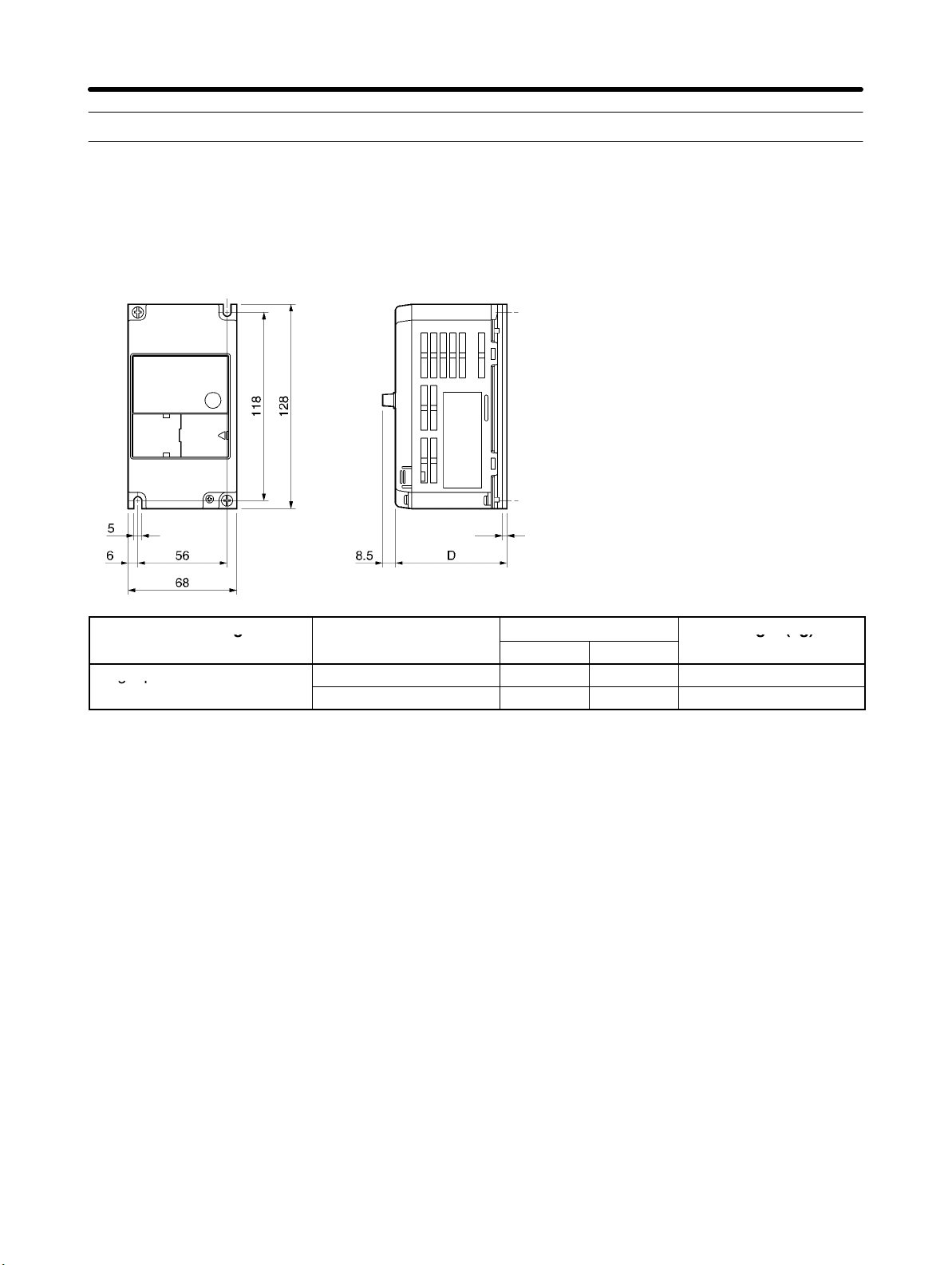
1-1-1 Dimensions
D 3G3JV-A1001, -A1002 (0.1 to 0.2 kW) Single-phase 100-V AC Input
t
Rated voltage Model 3G3JV-
Single-phase 100 V AC
A1001 80 3 Approx. 0.5
A1002 112 5 Approx. 0.8
Dimensions (mm)
D t
Weight (kg)
H Installation Direction and Dimensions
• Install the Inverter under the following conditions.
Ambient temperature for operation (panel-mounting): –10°C to 50°C
Humidity: 95% or less (no condensation)
• Install the Inverter in a clean location free from oil mist and dust. Alternatively, install it in a totally enclosed panel that is completely protected from floating dust.
• When installing or operating the Inverter, always take special care so that metal powder, oil, water, or
other foreign matter does not get into the Inverter.
• Do not install the Inverter on inflammable material such as wood.
H Direction
• Install the Inverter on a vertical surface so that the characters on the nameplate are oriented upward.
1-2
Page 17
Design Chapter 1
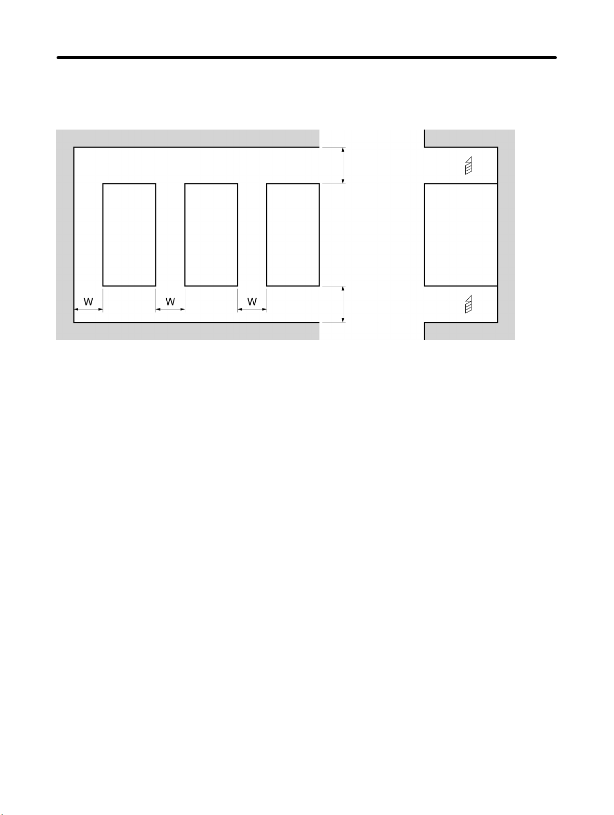
H Dimensions
• When installing the Inverter, always provide the following clearances to allow normal heat dissipation
from the Inverter.
W = 30 mm min.
Inverter
100 mm min. Air
SideInverter Inverter
100 mm min. Air
H Ambient Temperature Control
• To enhance operation reliability, the Inverter should be installed in an environment free from extreme
temperature changes.
• If the Inverter is installed in an enclosed environment such as a box, use a cooling fan or air conditioner
to maintain the internal air temperature below 50°C.
The life of the built-in electrolytic capacitors of the Inverter is prolonged by maintaining the internal air
temperature as low as possible.
• The surface temperature of the Inverter may rise approximately 30°C higher than the ambient temperature. Be sure to keep away equipment and wires from the Inverter as far as possible if the equipment
and wires are easily influenced by heat.
H Protecting Inverter from Foreign Matter during Installation
• Place a cover over the Inverter during installation to shield it from metal power produced by drilling.
Upon completion of installation, always remove the cover from the Inverter. Otherwise, ventilation will
be affected, causing the Inverter to overheat.
1-3
Page 18
Design Chapter 1
1-1-2 Removing and Mounting the Covers
It is necessary to remove the front cover, optional cover, top protection cover, and the
bottom protection cover from the Inverter to wire the terminal block.
Follow the instructions below to remove the covers from the Inverter.
To mount the covers, take the opposite steps.
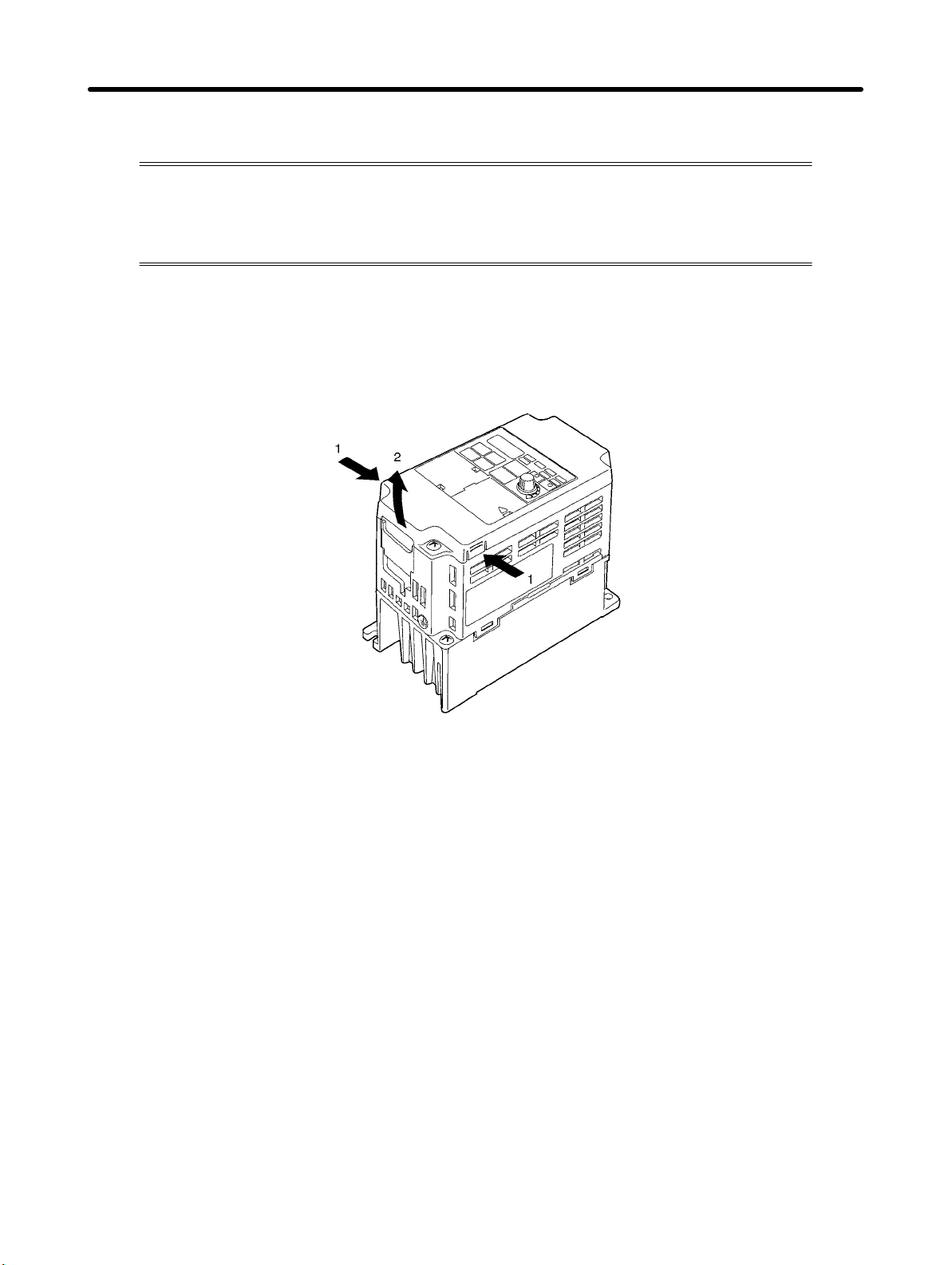
H Removing the Front Cover
• Loosen the front cover mounting screws with a screwdriver.
• Press the left and right sides of the front cover in the arrow 1 directions and lift the bottom of the cover in
the arrow 2 direction to remove the front cover as shown in the following illustration.
H Removing the Top and Bottom Protection Covers and Optional Cover
D Removing the Top and Bottom Protection Covers
• After removing the front cover, pull the top and bottom protection covers in the arrow 1 directions.
1-4
Page 19

Design Chapter 1
D Removing the Optional Cover
• After removing the front cover, lift the optional cover in the arrow 2 direction based on position A as a
fulcrum.
Note The front cover functions as a terminal cover. The Digital Operator cannot be removed.
1-5
Page 20
Design Chapter 1
1-2 Wiring
1-2-1 Terminal Block
Before wiring the terminal block, be sure to remove the front cover, top protection cover,
and the bottom protection cover.
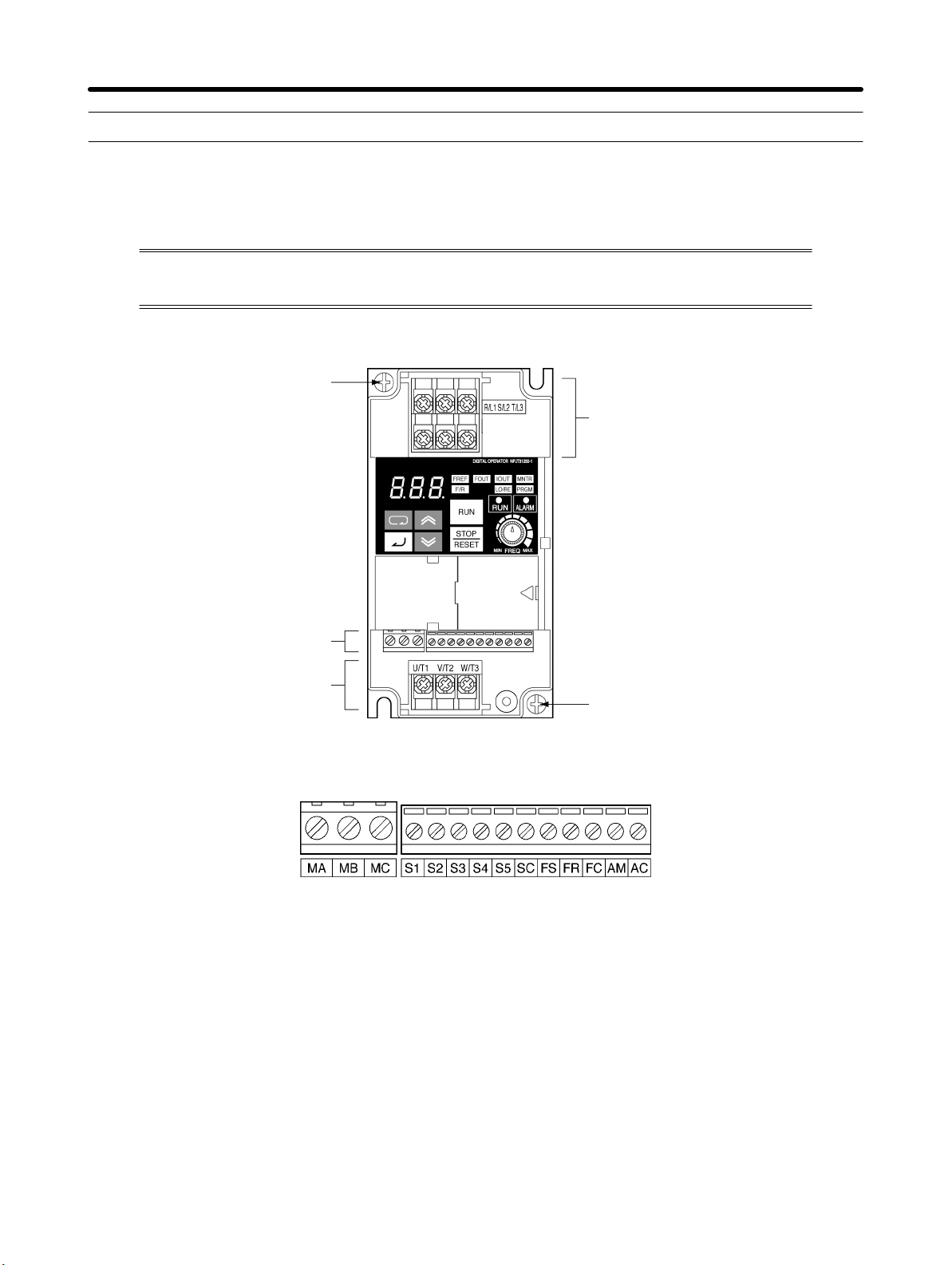
H Position of Terminal Block
Ground terminal
Main circuit input terminals
Control circuit terminals
Main circuit output terminals
H Arrangement of Control Circuit Terminals
Ground terminal
1-6
Page 21
pp y p
gp
p
pp ppyp g
3G3JV A1j: 3 phase 200 to 230 V AC
Design Chapter 1
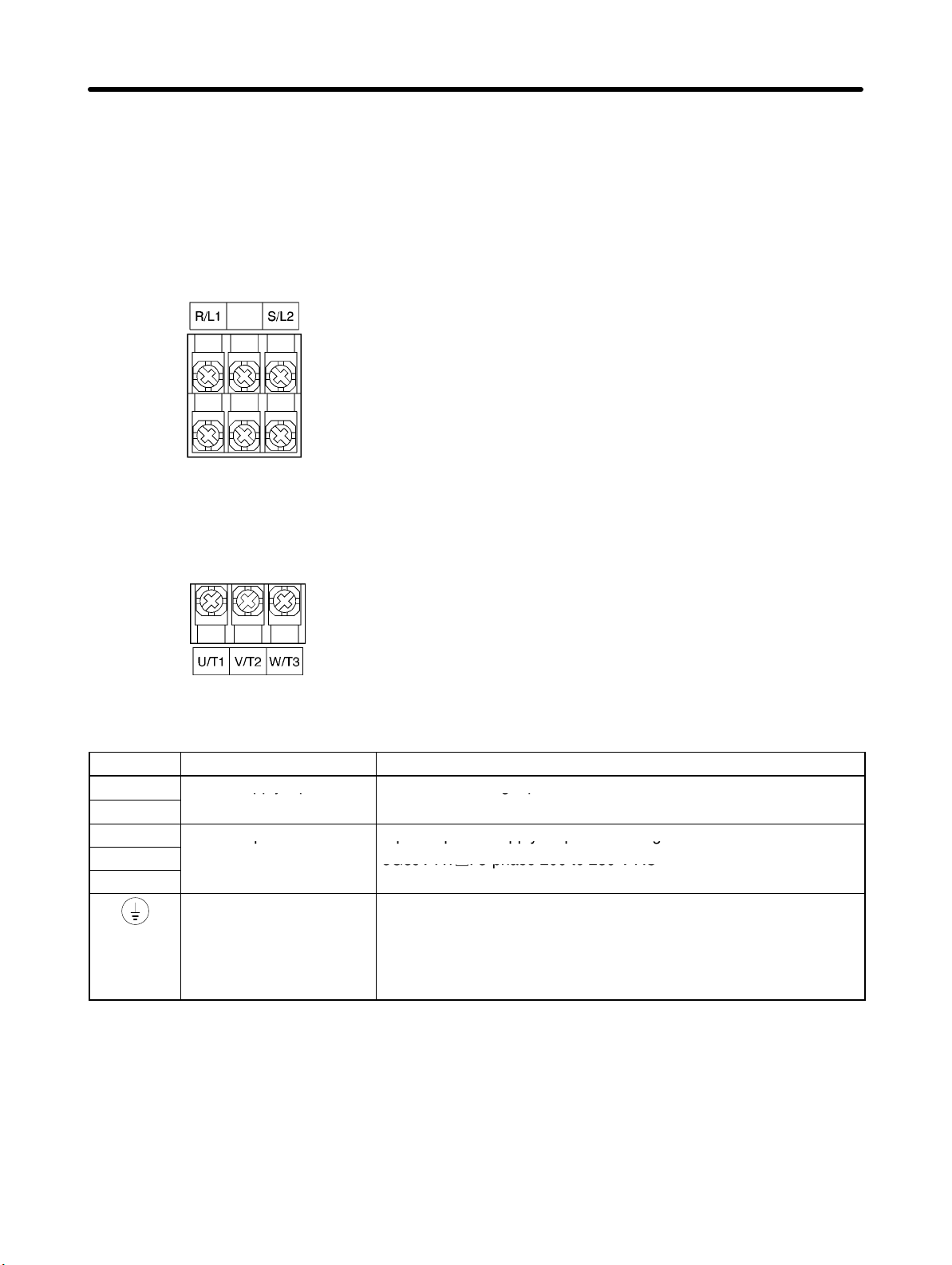
H Arrangement of Main Circuit Terminals
D 3G3JV-A1001, -A1002
Main Circuit Input Terminals
(Upper Side)
Main Circuit Output Terminals
(Lower Side)
H Main Circuit Terminals
Symbol Name Description
R/L1
S/L2
U/T1
V/T2
W/T3
Power supply input
terminals
Motor output terminals 3-phase power supply output for driving motors.
Ground terminal Be sure to ground the terminal under the following conditions.
Note The maximum output voltage corresponds to the power supply input voltage of the Inverter.
3G3JV-A1j: Single-phase 100 to 115 V AC
Note Connect single-phase input to terminals R/L1 and S/L2.
3G3JV-A1j: 3-phase 200 to 230 V AC
3G3JV-A1j: Ground at a resistance of 100 Ω or less, and connect
to the power supply’s neutral phase to conform to EC Directives.
Note Be sure to connect the ground terminal directly to the
motor frame ground.
1-7
Page 22
external power supply is
g
PNP
t
(p p 0 )
(g g)
30 C
Design Chapter 1
H Control Circuit Terminals
Symbol Name Function Signal level
Input
Output
S1 Forward/Stop Forward at ON. Stops at
OFF.
S2 Multi-function input 1
(S2)
S3 Multi-function input 2
(S3)
S4 Multi-function input 3
(S4)
S5 Multi-function input 4
(S5)
SC Sequence input com-
mon
FS Frequency reference
power supply
FR Frequency reference in-
put
FC Frequency reference
common
MA Multi-function contact
output (Normally open)
MB Multi-function contact
output (Normally closed)
MC Multi-function contact
output common
AM Analog monitor output Set by parameter n44
AC Analog monitor output
common
Set by parameter n36
(Reverse/Stop)
Set by parameter n37
(Fault reset)
Set by parameter n38
(External fault: Normally
open)
Set by parameter n39
(Multi-step reference 1)
Common for S1 through
S5
DC power supply for frequency reference use
Input terminal for frequency reference use
Common for frequency
reference use
Set by parameter n40
(during running)
Common for MA and
MB use
(Output frequency)
Common for AM use
Photocoupler
8 mA at 24 V DC
Note NPN is the default setting
for these terminals. Wire
them by providing a
common ground. No
required. To provide an
external power supply and
wire the terminals through
a common positive line,
however, set the SW7 to
and make sure tha
the power supply is at
24 V DC ±10%.
20 mA at 12 V DC
0 to 10 V DC
(input impedance: 20 kΩ)
Relay output
1 A max. at 30 V DC
1 A max. at 250 V AC
2 mA max. at 0 to 10 V DC
Note 1. Depending on the parameter settings, various functions can be selected for multi-function in-
puts and multi-function contacts outputs.
Note 2. Functions in parentheses are default settings.
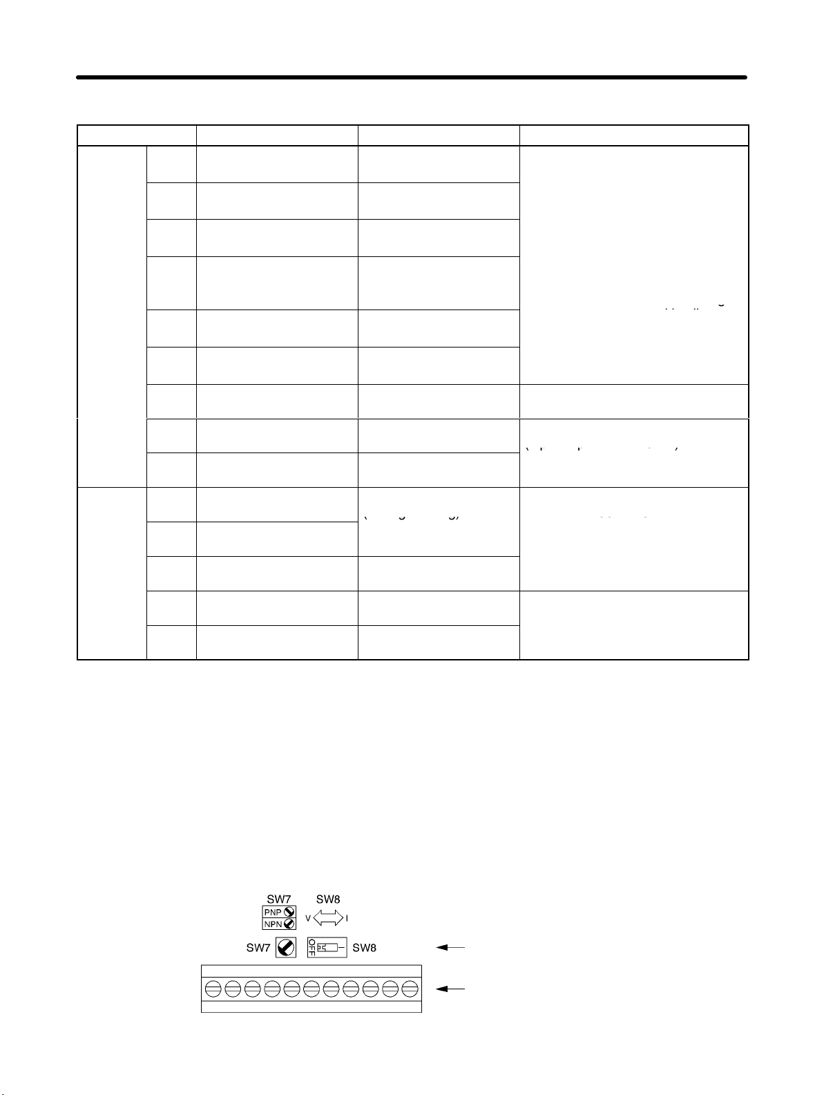
H Selecting Input Method
• Switches SW7 and SW8, both of which are located above the control circuit terminals, are used for
input method selection.
Remove the front cover and optional cover to use these switches.
1-8
Selector
Control circuit terminal
block
Page 23

Design Chapter 1
D Selecting Sequence Input Method
• By using SW7, NPN or PNP input can be selected as shown below.
SW7
SW7
D Selecting Frequency Reference Input Method
Frequency reference input
method
Voltage input V (OFF) Set value 2
Current input I (ON) Set value 3 or 4
SW8 setting Frequency reference selection
(parameter n03)
1-9
Page 24

,gp
Design Chapter 1
1-2-2 Standard Connections
DC reactor
(optional)
Single-phase 100 V AC
Forward/Stop
Multi-function input 1 (Reserve/Stop)
Multi-function input 2 (S3) (Fault Reset)
Multi-function input 3 (S4) (External fault
Normally open)
Multi-function input 4 (S5) (Multi-step speed
reference 1)
Sequence input common
Frequency reference power
supply 20 mA at +12 V
FREQ
adjuster
(2 kΩ, 1/4 W min.)
Frequency reference input
Frequency reference common
Noise Filter
3-phase 200 V AC
Multi-function contact output
NO
NC
Common
Analog monitor output
Analog monitor output common
Note 1. The braking resistor cannot be connected because no braking transistor is incorporated.
Note 2. A DC Reactor can be connected in series between the R input and L1 terminal or between the
S input and L2 terminal to use it as an AC reactor.
D DC Reactor Wiring Example
Noise Filter
Single-phase 100 V AC
DC Reactor
Applicable Noise Filters
Inverter Applicable Filter Specifications
3G3JV-A1001
3G3JV-A1002
3G3JV-PRS1010J
(for either 0.1 kW or 0.2 kW)
10 A at 250 V AC, single-phase
Applicable DC Reactors
Inverter Applicable Reactor Specifications
3G3JV-A1001 3G3HV-PUZDAB5.4A8MH 5.4 A, 8 mH
3G3JV-A1002 3G3HV-PUZDAB18A3MH 18 A, 3 mH
1-10
Page 25

Design Chapter 1
D Example of 3-wire Sequence Connections
Stop
switch
(NC)
RUN
switch
(NO)
Direction switch
RUN input (Operates with the stop switch and RUN switch closed.)
Stop input (Stops with the stop switch opened.)
Forward/Stop reference (Forward with the direction switch opened
and reverse with the direction switch closed.)
Sequence input common
Note Set parameter n37 for 3-wire sequence input.
1-2-3 Wiring around the Main Circuit
H Wire Size, Terminal Screw, Screw Tightening Torque, and Molded-case
Circuit Breaker Capacities
• For the main circuit and ground, always use 600-V polyvinyl chloride (PVC) cables.
• If any cable is long and may cause voltage drops, increase the wire size according to the cable length.
D Single-phase 100-V AC Model
Model
3G3JV-
A1001
A1002
Terminal symbol Terminal
R/L1, S/L2, U/T1, V/T2, W/T3
R/L1, S/L2, U/T1, V/T2, W/T3
Screw
screw
M3.5 0.8 to 1.0 0.75 to 2 2
M3.5 0.8 to 1.0 0.75 to 2 2
tightening
torque
(NSm)
H Wiring
Control Circuit
Terminal symbol Terminal
screw
MA, MB, MC M3 0.5 to 0.6 (4.4 to 5.3) Stranded wire:
S1 to S5, SC, FS,
FR, FC, AM, AC
M2 0.22 to 0.25 (2 to 2.2) Stranded wire:
Screw tightening
torque NSm (lbSin)
Wire size
2
mm
(AWG)
0.5 to 1.25 (20 to 16)
Single wire:
0.5 to 1.25 (20 to 16)
0.5 to 0.75 (20 to 18)
Single wire:
0.5 to 1.25 (20 to 16)
Wire size
2
(mm
)
Recommended
wire size (mm
Recommended
wire size
2
mm
(AWG)
0.75 (18)
0.75 (18)
2
)
1-11
Page 26

p
p
p
gp
j
Design Chapter 1
1-2-4 Optional Accessories
Option Specifications Model
EMC-compliant
Noise Filter
DC Reactor
DIN Track Mounting Bracket --- 3G3IV-PEZZ08122A
Adapter Panel
Operator Cable
Digital Operator
For A1001
For A1002
For A1001 3G3HV-PUZDAB5, 4A8MH
For A1002 3G3HV-PUZDAB18A3MH
Standard installation 3G3JV-PSI232J
Removable 3G3JV-PSI232JC
1 m 3G3IV-PCN126
3 m 3G3IV-PCN326
Without adjuster (with case) 3G3IV-PJVOP146
With adjuster
Main Unit 3G3IV-PJVOP140
Case 3G3IV-PEZZ08386
3G3JV-PRS1010J
1-12
Page 27

p
qyp (p
Design Chapter 1
1-3 Specifications
100-V AC Models 3G3JV-A1001 3G3JV-A1002
Power
supply
Heating radiation (W) 14.6 21.1
Weight (kg) 0.5 0.8
Cooling method Natural cooling
Maximum motor capacity (kW) 0.1 0.2
Output
specifications
Control
characteristics
Rated voltage and power supply Single-phase 100 to 115 V AC at 50/60 Hz
Allowable voltage fluctuation –15 to 10%
Allowable frequency fluctuation ±5%
Input current (for rated output) (A) 3.2 6.2
Rated output capacity (kVA) 0.3 0.6
Rated output current (A) 0.8 1.6
Rated output voltage (V) Three-phase 200 to 230 V (Handles twice the input volt-
age.)
Maximum output frequency 400 Hz (Set in a parameter.)
Power supply harmonics counter-
measures
Control method Sine wave PWM (V/f control)
Carrier frequency 2.5 to 10.0 kHz (Switched in steps.)
Frequency control range 0.1 to 400 Hz
Frequency precision (tempera-
ture characteristics)
Frequency setting resolution
Output frequency resolution 0.01 Hz (data processing resolution)
Overload capacity 150% of rated output current for 1 min
External frequency set signal Switchable: 0 to 10 V DC (20 kΩ), 4 to 20 mA (250 Ω), 0 to
Acceleration/deceleration times 0.0 to 999 s (Acceleration and deceleration times set sepa-
Braking torque Approx. 20%
Voltage/frequency characteristics User-set V/f pattern
DC Reactor (optional) can be connected.
Digital reference: ±0.01% (–10 to 50°C)
Analog reference: ±0.5% (25°C ±10°C)
Digital reference: 0.1 Hz (less than 100 Hz), 1 Hz (100 Hz
or greater)
Analog reference: 0.06 Hz/60 Hz (equivalent to 1/1000)
20 mA (250 Ω), or frequency adjustment
rately: Switches between 2 settings.)
Note: A Braking Resistor or Braking Resistor Unit cannot be
connected.
1-13
Page 28

Design Chapter 1
3G3JV-A10023G3JV-A1001100-V AC Models
Protective
functions
Environment
Degree of protection Mounted in a panel (equivalent to IP20)
Motor protection Protection by electronic thermal
Instantaneous overcurrent
protection
Overload protection Stops in 1 min at approximately 150% of rated output cur-
Overvoltage protection Stops when main-circuit DC voltage is approximately 410 V.
Undervoltage protection Stops when main-circuit DC voltage is approximately 160 V.
Momentary power interruption
compensation (selection)
Radiation fin overheated Detected at 110°C ±10°C
Grounding protection Rated output current level protection
Charge indicator CHARGE indicator lights until the main circuit DC voltage
Location Indoors (with no corrosive gas, dust, etc.)
Ambient operating temperature –10 to 50°C
Ambient operating humidity 95% max. (with no condensation)
Storage temperature –20 to 60°C
Altitude 1,000 m max.
Insulation resistance 5 MΩ min. (Do not carry out any insulation resistance or
Vibration resistance 9.8 m/s2 max. between 10 and 20 Hz, 2.0 m/s2 max. be-
Stops at approx. 250% of rated output current.
rent.
None (Stops at 15 ms or longer.)
Select between continuing operation if power is restored
within approx. 0.5 s or continuing operation regardless of
length of interruption.
reaches 50 V or less.
withstand voltage tests.)
tween 20 and 50 Hz
1-14
Page 29

2
Chapter 2
Preparing for
Operation and
Monitoring
2-1 Using the Digital Operator
2-2 Copying and Verifying Parameters
Page 30

Preparing for Operation and Monitoring Chapter 2
2-1 Using the Digital Operator
2-1-1 Nomenclature
Data display
Keys
Appearance Name Function
Data display Displays relevant data items, such as frequency reference,
output frequency, and parameter set values.
FREQ adjuster Sets the frequency reference within a range between 0 Hz
and the maximum frequency.
FREF indicator The frequency reference can be monitored or set while this
indicator is lit.
FOUT indicator The output frequency of the Inverter can be monitored
while this indicator is lit.
IOUT indicator The output current of the Inverter can be monitored while
this indicator is lit.
MNTR indicator The values set in U01 through U10 are monitored while
this indicator is lit.
F/R indicator The direction of rotation can be selected while this
indicator is lit, when operating the Inverter with the RUN
Key.
LO/RE indicator The operation of the Inverter through the Digital Operator
or according to the parameters set is selectable while this
indicator is lit.
Indicators
Setting/Monitor item indicators
FREQ adjuster
2-2
Note This status of this indicator can be only monitored
while the Inverter is in operation. Any RUN command
input is ignored while this indicator is lit.
PRGM indicator The parameters in n01 through n79 can be set or
monitored while this indicator is lit.
Note While the Inverter is in operation, the parameters can
be only monitored and only some parameters can be
changed. The RUN command input is ignored while
this indicator is lit.
Mode Key Switches the setting and monitor item indicators in
sequence.
Parameter setting being made is canceled if this key is
pressed before entering the setting.
Increment Key Increases multi-function monitor numbers, parameter
numbers, and parameter set values.
Page 31

Preparing for Operation and Monitoring Chapter 2
Appearance FunctionName
Decrement Key Decreases multi-function monitor numbers, parameter
numbers, and parameter set values.
Enter Key Enters multi-function monitor numbers, parameter
numbers, and internal data values after they are set or
changed.
RUN Key Starts the Inverter running when the 3G3FV is in operation
with the Digital Operator.
STOP/RESET Key Stops the Inverter unless n06 is set to disable the STOP
Key. Functions as a Reset Key when an Inverter error
occurs. (See note.)
Note For safety’s reasons, the reset will not work while a RUN command (forward or reverse) is in ef-
fect. Wait until the RUN command is OFF before resetting the Inverter.
2-3
Page 32

()
Preparing for Operation and Monitoring Chapter 2
2-1-2 Accepting Operation Commands While Changing
Parameters
With the default settings, the Inverter will not accept operation commands when parameter settings are being changed. This functions as a safety measure to prevent the motor
from rotating if the operation command is mistakenly set to ON when changing parameters.
Depending on the operating conditions, however, the user may want to have operation
commands accepted even while parameters are being changed. In that case, change
the following settings.
H Using the Indicators to Determine When Operation Commands Can Be
Accepted
The indicators on the Digital Operator can be used to determine if operation commands will be accepted
or not while changing parameters.
Green: Operation commands will be accepted if the indicator lights green.
Red: Operation commands will not be accepted after the Inverter stops if an indicator lights red.
Therefore, if the indicator lights red when changing parameters or when switching between local and
remote operation, operation will continue, but once the Inverter stops, the Inverter will not operate even
if the operation command is set to ON again.
The FREF indicator will light when the power supply is turned ON.
Indicator Color Name
FREF Green Frequency Reference/Monitor
FOUT Green Output Frequency Monitor
IOUT Green Output Current Monitor
MNTR Green Multi–function Monitor
F/R Green Operator RUN command forward/reverse
operation selection
LO/RE Red Local/Remote Selection
PRGM Red Parameter Number/Setting
Note Perform the settings given in the following description to have operation commands accepted
while the red indicator is lit (i.e., while changing parameters or switching between local and remote.)
Set n01 (Parameter write–prohibit selection/parameter initialization) to 5.
S The default value for n01 is 1.
S Operation commands will not be accepted when n01 itself is being changed.
S Some parameters cannot be changed during operation. Those parameters cannot be changed
during operation even if the setting for n01 is changed.
Acceptance of operation
commands
During
operation
Yes Yes
Yes No (See note.)
Stopped
S When n01 is changed to 5, an operation command will be accepted even when changing pa-
rameters, such as during trial operation. Thoroughly check safety before changing any setting.
2-4
Page 33

Preparing for Operation and Monitoring Chapter 2
2-1-3 Outline of Operation
H Selecting Indicators
Whenever the Mode Key is pressed, an indicator is lit in sequence beginning with the
FREF indicator. The data display indicates the item corresponding to the indicator selected.
The FOUT or IOUT indicator will be lit by turning the Inverter on again if the Inverter is
turned off while the FOUT or IOUT indicator is lit. The FREF indicator will be lit by turning
the Inverter on again if the Inverter is turned off while an indicator other than the FOUR or
IOUT indicator is lit.
Power On
FREF (Frequency Reference)
Monitors and sets the frequency reference.
FOUT (Output Frequency)
Monitors the output frequency.
Note This indicator will be lit by turning the Inverter on again if the Inverter
is turned off while this indicator is lit.
IOUT (Output Current)
Monitors the output current.
Note This indicator will be lit by turning the Inverter on again if the Inverter
is turned off while this indicator is lit.
MNTR (Multi-function Monitor)
Monitors the values set in U01 through U10.
F/R (Forward/Reverse Rotation)
Selects the direction of rotation.
LO/RE (Local/Remote)
Selects the operation of the Inverter through the Digital Operator or
according to the parameters.
PRGM (Parameter Setting)
Monitors or sets the values in n01 through n79.
The FREF indicator is lit again.
2-5
Page 34

p
p
g(
Preparing for Operation and Monitoring Chapter 2
H Example of Multi-function Display
Key sequence Indicator Display Explanation
Power On
Press the Mode Key repeatedly until the MNTR
indicator is lit.
U01 will be displayed.
Use the Increment or Decrement Key to select the
monitor item to be displayed.
Press the Enter Key so that the data of the selected
monitor item will be displayed.
The monitor number display will appear again by
pressing the Mode Key.
D Status Monitor
Item Display Display
unit
U01 Frequency
reference
U02 Output frequency Hz Monitors the output frequency. (Same as FOUT)
U03 Output current A Monitors the output current. (Same as IOUT)
U04 Output voltage V Monitors the internal output voltage reference value of the
U05 DC bus voltage V Monitors the DC voltage of the internal main circuit of the
U06 Input terminal ---
status
Hz Monitors the frequency reference. (Same as FREF)
Inverter.
Inverter.
Shows the ON/OFF status of inputs.
Function
: Input ON : No input
Terminal S1: Forward/Stop
Terminal S2: Multi-function input 1 (S2)
Terminal S3: Multi-function input 2 (S3)
Not
used
U07 Output terminal ---
status
U09 Error log (most
recent one)
U10 Software No. --- OMRON use only.
U15 Receive data error --- The cause of the receive data error during MEMOBUS
---
Shows the ON/OFF status of outputs.
Not
used
Displays the latest error.
communications can be checked. (Same as the contents of
communications register number 003DM.)
Terminal S4: Multi-function input 3 (S4)
Terminal S5: Multi-function input 4 (S5)
: Closed : Open
Terminal MA: Multi-function contact
output
Error
2-6
Page 35

Preparing for Operation and Monitoring Chapter 2
2-2 Copying and Verifying Parameters
The 3G3IV-PJVOP140 and 3G3IV-PJOP146 Digital Operators contain an EEPROM.
All Inverter parameter settings, the Inverter capacity, and the software number are recorded in this EEPROM. The EEPROM can be used to copy parameter settings to other
Inverters.
Parameter settings can be copied between Inverters with the same power supply specifications, but some of the parameter settings are not copied.
2-2-1 Parameters Used to Copy and Verify Parameters
• The following parameters are used to read, copy (write), and verify parameter settings.
Param-
eter
No.
(Regis-
ter No.
(Hex))
n76
(014C)
n77
(014D)
Name Description Setting
Parameter
copy and
verify func-
tion
Parameter
read pro-
hibit selec-
tion
Selects the function for copying parameters.
rdy: Ready to accept the next command.
rED: Reads the Inverter parameters.
Cpy: Copies the parameter to the Inverter.
vFY: Verifies the Inverter parameters.
vA: Checks the Inverter capacity display.
Sno: Checks the software number.
Selects the copy-prohibit function.
Use this parameter to protect the data in the
EEPROM of the Digital Operator.
0: Read prohibited for Inverter parameters.
(Data cannot be written to EEPROM.)
1: Read possible for Inverter parameters.
(Data can be written to EEPROM.)
rdy to
Sno
0, 1 --- 0 No
range
Setting
unit
--- rdy No
Default
setting
Changes
during
opera-
tion
2-7
Page 36

Preparing for Operation and Monitoring Chapter 2
H Display Transitions
Reading
Writing
Verifying
Inverter capacity
Software number
Reading
finished
Writing
finished
Verification
finished
OR
OR
OR
OR
OR
Note The following display is an example of the capacity displayed. The values in parentheses indicate
the capacities for European motors.
10.1
Voltage Class
1: Single-phase 100 V
Max. applicable motor capacity
0.1: 0.1 kW (0.1 kW)
0.2: 0.25 kW/0.37 kW (0.2 kW)
Note The values in parentheses indicate Japanese motor capacities.
2-8
Page 37

Preparing for Operation and Monitoring Chapter 2
2-2-2 Outline of Copying Parameters
(1) Check setting of n01
0: Writing from Digital Operator prohibited.
1: Parameters can be changed (default setting).
(2) Clear prohibition of reading the copy function: n77
This function protects parameters stored in the Digital
Operator.
0: Reading copy function (rEd) prohibited (default setting).
1: Reading copy function (rEd) enabled.
(3) Perform the read operation for the copy function: n76
Read (rEd) the current parameter settings from the Inverter
to the EEPROM in the Digital Operator.
(4) Disconnect the Digital Operator and connect it to a
different Inverter. Always turn OFF the power supply
before connecting or disconnecting the Digital Operator
to protect against electric shock and product failure.
Set n01 to 1.
See operation on next page.
Set n77 to 1.
Same basic operation as for n01.
Set n76 to rEd.
Change Inverter connection.
Turn ON power after checking wiring.
(5) Perform the write operation for the copy function: n76
Write (CPy) the current parameter settings from the EEPROM in the Digital Operator to the Inverter.
(6) Perform the verify operation for the copy function: n76
Verify (vFy) the current parameter settings between the
EEPROM in the Digital Operator and the Inverter.
Set n76 to CPy.
Set n76 to vFy.
H Parameters That Cannot Be Copied
1. Copying is not possible between Inverters with different power supply specifications (e.g., from a
100-V Inverter to a 400-V Inverter).
2. The recorded hold output frequency and the following parameters cannot be copied:
n76: Parameter copy and verify function
n77: Parameter read prohibit selection
n78: Error log
n79: Software number
3. The following parameters cannot be copied if the Inverters have different capacities.
n09 to n15: V/f settings
n32: Rated motor current
n46: Carrier frequency selection
2-9
Page 38

Preparing for Operation and Monitoring Chapter 2
n64: Motor rated slip
n65: Motor no-load current
2-2-3 Procedures
Changing Parameters
The setting of n01 is changed so that n76 and n77 can be displayed.
D Setting n01 (Parameter Write-prohibit Selection/Parameter Initialization Parameter)
Key Indicator Display Description
--- (Display after the power supply is turned ON.)
Press the Mode Key until the PRGM indicator lights.
Confirm that n01 is displayed on the data display.
Press the Enter Key.
The setting of the specified parameter number will be
displayed.
Press the Increment Key until 4 is displayed. (The display will
flash.)
Press the Enter Key to confirm the setting. (The display will
stop flashing.)
After about 1 s The display of the parameter number will return in about 1 s.
2-10
Page 39

Preparing for Operation and Monitoring Chapter 2
Example of Copy Function
H Verifying Parameters (vFy)
• The Parameter Copy and Verify Function (n76) can be set to “vFy” to compare the parameter settings
in the Digital Operator with those in the Inverter.
D Verifying Parameters
Key Indicator Display Description
--- (Display after the power supply is turned ON.)
Press the Mode Key until the PRGM indicator lights.
Confirm that n01 is displayed on the data display.
Press the Increment/Decrement Key until “n76” is
displayed.
Press the Enter Key.
“rdy” will be displayed.
Press the Increment Key until “vFy” is displayed
(After
comparison is
finished.)
or
Press the Enter Key. The parameter settings will be
compared and the display will flash.
The parameter number of any parameter that has different
settings will be displayed.
Press the Enter Key.
The setting of the parameter in the Inverter will be displayed
(flashing) first.
Press the Enter Key again.
The setting of the parameter in the Digital Operator will be
displayed (flashing) next.
Press the Increment Key.
The comparison will be continued.
“End” will be displayed when the comparison has been
finished.
Press the Mode Key or Enter Key.
The display of the parameter number will return.
2-11
Page 40

Preparing for Operation and Monitoring Chapter 2
2-2-4 Error Messages for Copying and Verifying Parameters
The errors that can be displayed when reading, writing, or verifying parameter settings are described in
the following table along with corrective actions. All of these error displays will flash on the display.
Display Name Description Corrective action
pre
rde
cse
ndt
cpe
cye
Ure
ife
Protect error An attempt was made to read
parameter settings when the
Parameter Read Prohibit Selection
parameter (n77) was set to 0
(prohibiting reading).
Read error The parameter settings could not be
read normally or a low main circuit
voltage was detected while reading
parameter settings.
Checksum error A checksum error occurred for the
parameters recorded in the Digital
Operator.
No data error No parameters are recorded in the
Digital Operator.
Copy source
error
Voltage error
while copying
Capacity error Verification was attempted between
Communications
error
Copying or verifying parameter
settings was attempted between
Inverters with different voltage
classes.
A low main circuit voltage was
detected while reading parameter
settings.
Inverters of different capacities.
A communications error occurred
between the Inverter and Digital
Operator.
Confirm that it is necessary to read
the parameter settings. If it is, change
the Parameter Read Prohibit
Selection parameter (n77) to 1
(enabling reading).
Check the main circuit voltage and
then attempt reading again.
Read the parameter settings again to
record them in the Digital Parameter.
Read the parameter settings to record
them in the Digital Parameter.
Check the voltage classes. (They
must both be the same to copy
parameter settings.)
Check the main circuit voltage and
then attempt copying again.
Press the Enter Key to continue the
comparison.
Press the STOP/RESET Key to
cancel the comparison.
Check the connection between the
Inverter and the Digital Operator.
Correct any problems and then repeat
the operation.
2-12
Page 41

3
Chapter 3
List of Parameters
Page 42

List of Parameters Chapter 3
Parameter
No. (Reg-
ister No.
(Hex))
n01
(0101)
n02
(0102)
Name Description Setting
range
Parameter
writeprohibit
selection/
parameter initialization
Operation
command
selection
Used to prohibit parameters to be
written, sets parameters, or change
the monitor range of parameters.
Used to initialize parameters to
default values.
0: Sets or monitors parameter n01.
Parameters n02 through n79 can
be monitored only.
1: Sets or monitors parameters n01
through n79.
5: Operation commands can be ac-
cepted at any time (n01 to n79 can
be set or referenced). (See note.)
6: Clears the error log.
8: Initializes parameters to default
values in 2-wire sequence.
9: Initializes parameters to default
values in 3-wire sequence.
Note Operation commands will be ig-
nored in Program Mode (refer
to 2-1-2) when n01 is set to 0 or
1. Normally set n01 to 0 or 1.
Used to select the input method for
the RUN and STOP commands in
remote mode.
0: The RUN and STOP/RESET Keys
on the Digital Operator are enabled.
1: Multi-function inputs through the
control circuit terminals in 2- or
3-wire sequence.
2: Operation commands via
RS-422A/485 communications are
enabled.
Note The RUN command only
through key sequences on the
Digital Operator is acceptable
in local mode.
0, 1, 6, 8,91 No
0 to 2 0 No
Default
setting
Changes
during
opera-
tion
Memo
3-2
Page 43

List of Parameters Chapter 3
Parameter
No. (Reg-
ister No.
(Hex))
n03
(0103)
n04
(0104)
Frequency
reference
selection
Interruption
mode
selection
DescriptionName
Used to set the input method for the
frequency reference in remote mode.
0: Digital Operator
1: Frequency reference 1 (n21)
2: Frequency reference control circuit
terminal (0 to 10 V)
3: Frequency reference control circuit
terminal (4 to 20 mA)
4: Frequency reference control circuit
terminal (0 to 20 mA)
6: Frequency reference via
RS-422A/485 communications
Used to set the stopping method for
use when the STOP command is input.
0: Decelerates to stop in preset time.
1: Coasts to stop (with output shut off
by the STOP command)
Setting
range
0 to 4, 6 0 No
0, 1 0 No
Default
setting
MemoChanges
during
opera-
tion
n05
(0105)
n06
(0106)
n07
(0107)
n08
(0108)
Reverse
rotationprohibit
selection
STOP/
RESET
Key
function
selection
Frequency
selection in
local
mode
Key sequential
frequency setting
Used to select the operation with the
reverse command input.
0: Reverse enabled.
1: Reverse disabled.
Used to select the stop method in remote mode with n02 for operation
mode selection set to 1.
0: STOP/RESET Key of the Digital
Operator enabled.
1: STOP/RESET Key of the Digital
Operator enabled only when the
Digital Operator is selected for the
RUN command.
Used to set the input method for the
frequency reference in local mode.
0: The FREQ adjuster of the Digital
Operator enabled.
1: Key sequences on the Digital Op-
erator enabled.
Used to enable the Enter Key for setting the frequency reference with the
Increment and Decrement Keys.
0: The value is entered with the En-
ter Key pressed.
1: The value is enabled when the
value is input.
0, 1 0 No
0, 1 0 No
0, 1 0 No
0, 1 0 No
3-3
Page 44

()()()( )
(Acceleration/Deceleration
List of Parameters Chapter 3
Parameter
No. (Reg-
ister No.
(Hex))
n09
(0109)
Maximum
frequency
(FMAX)
n10
(010A)
Maximum
voltage
(VMAX)
n11
(010B)
Maxi-
mum
voltage
frequen-
cy (FA)
n12
(010C)
Middle
output
frequen-
cy (FB)
n13
(010D)
Middle
output
frequen-
cy volt-
age
(VC)
n14
(010E)
Mini-
mum
output
frequen-
cy
(FMIN)
n15
(010F)
Mini-
mum
output
frequen-
cy volt-
age
(VMIN)
n16
(0110)
n17
(0111)
n18
(0112)
n19
(0113)
Accel-
eration
time 3
Decel-
eration
time 3
Accel-
eration
time 4
Decel-
eration
time 4
DescriptionName
Used to set the V/f pattern as the basic characteristic of the Inverter with
output voltage per frequency set.
Output
voltage
n10
(VMAX)
n13
(VC)
n09
(FMAX)
Frequency
(Hz)
n15
(VMIN)
0 n14
(FMIN)
n12
(FB)
n11
(FA)
Note Set the parameters so that
the following condition will be
satisfied.
n14 x n12 < n11 x n09
Note The value set in n13 will be
ignored if parameters n14 and
n12 are the same in value.
Acceleration time: The time required
to go from 0% to 100% of the maximum frequency.
Deceleration time: The time required
to go from 100% to 0% of the maximum frequency.
Note The actual acceleration or de-
celeration time is obtained
from the following formula.
Acceleration/Deceleration time
=
=
time set value) × (Frequency
reference value) ÷ (Max. fre-
quency)
Setting
range
50.0 to
Default
setting
60.0 No
400
1 to 255 200 No
0.2 to 400 60.0 No
0.1 to 399 1.5 No
1 to 255 12 No
0.1 to 10.0 1.5 No
1 to 50
12.0 No
(see note
2)
0.0 to 999
10.0 Yes
10.0 Yes
10.0 Yes
10.0 Yes
MemoChanges
during
opera-
tion
3-4
Page 45

List of Parameters Chapter 3
Parameter
No. (Reg-
ister No.
(Hex))
n20
(0114)
S-shape
acceleration/
deceleration
characteristic
DescriptionName
Used to set S-shape acceleration/deceleration characteristics.
0: No S-shape acceleration/decelera-
tion (trapezoidal acceleration/deceleration)
1: S-shape acceleration/deceleration
characteristic time 0.2 s
2: S-shape acceleration/deceleration
characteristic time 0.5 s
3: S-shape acceleration/deceleration
characteristic time 1.0 s
Note When the S-shape accelera-
tion/deceleration characteristic
time is set, the acceleration
and deceleration times will be
lengthened according to the
S-shape at the beginning and
end of acceleration/deceleration.
Setting
range
0 to 3 0 No
Default
setting
MemoChanges
during
opera-
tion
3-5
Page 46

abled in remote mode with
ith
lti-st
List of Parameters Chapter 3
Parameter
No. (Reg-
ister No.
(Hex))
n21
(0115)
n22
(0116)
n23
(0117)
n24
(0118)
n25
(0119)
n26
(011A)
n27
(011B)
n28
(011C)
n29
(011D)
Frequency
reference 1
Frequency
reference 2
Frequency
reference 3
Frequency
reference 4
Frequency
reference 5
Frequency
reference 6
Frequency
reference 7
Frequency
reference 8
Inching
frequency command
DescriptionName
Used to set internal frequency references.
Note Frequency reference 1 is en-
abled in remote mode with
n03 for frequency reference
selection set to 1.
Note These frequency references
are selected w
speed references (multi-function input).
Used to set the inching frequency
command.
Note The inching frequency com-
mand is selected with the
inching command (multi-function input). The inching frequency command takes precedence over the multi-step
speed reference.
mu
ep
Setting
range
0.0 to max.
frequency
Default
setting
6.0 Yes
0.0 Yes
0.0 Yes
0.0 Yes
0.0 Yes
0.0 Yes
0.0 Yes
0.0 Yes
6.0 Yes
during
opera-
MemoChanges
tion
3-6
Page 47

p
than the minimum output fre-
List of Parameters Chapter 3
Parameter
No. (Reg-
ister No.
(Hex))
n30
(011E)
n31
(011F)
n32
(0120)
n33
(0121)
Frequency
reference
upper
limit
Frequency
reference
lower
limit
Rated
motor
current
Motor
protection
characteristics
DescriptionName
Used to set the upper and lower frequency reference limits in percentage based on the maximum frequency as 100%.
Note If n31 is set to a value less
than the minimum out
quency (n14), the Inverter will
have no output when a frequency reference less than
the minimum output frequency
input is input.
Used to set the rated motor current
for motor overload detection (OL1)
based on the rated motor current.
Note Motor overload detection
(OL1) is disabled by setting
the parameter to 0.0.
Note The rated motor current is
default to the standard rated
current of the maximum applicable motor.
Used to set the motor overload
detection (OL1) for the electronic
thermal characteristics of the motor.
0: Protection characteristics for gen-
eral-purpose induction motors
1: Protection characteristics for in-
verter-dedicated motors
2: No protection
Note If a single Inverter is con-
nected to more than one motor, set the parameter to 2 for
no protection. The parameter
is also disabled by setting n32
for rated motor to 0.0.
ut fre-
Setting
range
0 to 110 100 No
0 to 110 0 No
0.0 to
120% of
rated output current
of the Inverter.
0 to 2 0 No
Default
setting
Varies with
the capacity.
No
MemoChanges
during
opera-
tion
3-7
Page 48

List of Parameters Chapter 3
Parameter
No. (Reg-
ister No.
(Hex))
n34
(0122)
n35
(0123)
Motor
protective time
setting
Cooling
fan operation
function
DescriptionName
Used to set the electric thermal characteristics of the motor to be connected in 1-minute increments.
Note The default setting does not
require any changes in normal
operation.
Note To set the parameter accord-
ing to the characteristics of the
motor, check with the motor
manufacturer the thermal time
constant and set the parameter with some margin. In other
words, set the value slightly
shorter than the thermal time
constant.
Note To detect motor overloading
quicker, reduce the set value,
provided that it does not cause
any application problems.
Used to operate the Cooling Fan of
the Inverter while the Inverter is
turned on or only while the Inverter is
in operation.
0: Rotates only while RUN command
is input and for 1 minute after Inverter stops operating
1: Rotates while Inverter is turned on
Note This parameter is available
only if the Inverter incorporates a Cooling Fan.
Note If the operation frequency of
the Inverter is low, the life of
the fan can be prolonged by
setting the parameter to 0.
Setting
range
1 to 60 8 No
0, 1 0 No
Default
setting
MemoChanges
during
opera-
tion
3-8
Page 49

(0124)
p
0
tion input 4
10 to
List of Parameters Chapter 3
Param-
eter
No.
(Regis-
ter No.
(Hex))
n36
n37
(0125)
n38
(0126)
n39
(0127)
Name Description Set-
Multi-function input 1
(Input terminal S2)
Multi-function input 2
(Input terminal S3)
Multi-function input 3
(Input terminal S4)
Multi-func-
(Input terminal S5)
Used to select the functions of multi-function
input terminals S2 through S5.
Set
val-
0 Forward/
2 Reverse/
3 External
4 External
5 Fault reset ON: Fault reset (disabled
6 Multi-step
7 Multi-step
8 Multi-step
10 Inching fre-
11 Accelera-
Function Description
ue
3-wire sequence (to be
Reverse
rotation
command
Stop
fault (NO)
fault (NC)
speed reference 1
speed reference 2
speed reference 3
quency
command
tion/Deceleration time
changeover
set in n37 only)
By setting n37 to 0, the
set value in n36 is ig-
nored and the following
setting are forcibly made.
S1: RUN input (RUN
when ON)
S2: STOP input (STOP
when OFF)
S3: Forward/Reverse
rotation command (OFF:
Forward; ON: Reverse)
Reverse rotation com-
mand in 2-wire sequence
(Reversed with the termi-
nal turned ON)
ON: External fault (FPj
detection: j is a terminal
number)
OFF: External fault (EFj
detection: j is a terminal
number)
while RUN command is
input)
Signals to select frequen-
cy references 1 through
8.
ON: Inching frequency
command (taking prece-
dence over the multi-step
speed reference)
ON: Acceleration time 2
and deceleration time 2
are selected.
ting
range
2 to 8,
10 to
22
0, 2 to
8, 10
to 22
2 to 8,
10 to
22
2 to 8,
22,
34, 35
Default
setting
2 No
5 No
3 No
6 No
Changes
Memo
during
opera-
tion
3-9
Page 50

)
List of Parameters Chapter 3
Param-
eter
No.
(Regis-
ter No.
(Hex))
n39
(0127)
Multi-function input 4
(Input terminal S5)
12 External
base block
command
(NO)
13 External
base block
command
(NC)
14 Search
command
(Searching
starts from
maximum
frequency)
15 Search
command
(Searching
starts from
preset frequency)
16 Accelera-
tion/Deceleration-prohibit command
17 Local or re-
mote selection
18 Commu-
nications or
remote
selection
DescriptionName
ON: Output shut off
(while motor coasting to a
stop and “bb” flashing)
OFF: Output shut off
(with motor free running
and “bb” flashing)
ON: Speed search
(Searching starts from
n09)
ON: Speed search
ON: Acceleration/Deceleration is on hold (running at parameter frequency)
ON: Local mode (operated with the Digital Operator)
ON: RS-422A/485 communications input is
enabled.
OFF: The settings of n02
and n03 are enabled.
Setting
range
2 to 8,
10 to
22,
34, 35
Default
setting
6 No
MemoChanges
during
opera-
tion
3-10
Page 51

gency stop input turned
gyp
(
List of Parameters Chapter 3
Param-
eter
No.
(Regis-
ter No.
(Hex))
n39
(0127)
Multi-function input 4
(Input terminal S5)
19 Emergency
stop fault
(NO)
20 Emergency
stop alarm
(NO)
21 Emergency
stop fault
(NC)
22 Emergency
stop alarm
(NC)
34 Up or down
command
35 Self-diag-
nostic test
DescriptionName
The Inverter stops according to the setting in
n04 for interruption mode
selection with the emer-
ON.
NO: Emergency stop with
the contact closed.
NC: Emergency stop with
the contact opened.
Fault: Fault output is ON
and reset with RESET
input. Alarm output is ON
no reset required).
“STP” is displayed (lit
with fault input ON and
flashes with alarm input
ON)
Up or down command
(set in n39 only)
By setting n39 to 34, the
set value in n38 is ignored and the following
setting are forcibly made.
S4: Up command
S5: Down command
ON: RS-422A/485 communications self-diagnostic test (set in n39 only)
Setting
range
2 to 8,
10 to
22,
34, 35
Default
setting
6 No
MemoChanges
during
opera-
tion
3-11
Page 52

(0128)
p
0
List of Parameters Chapter 3
Param-
eter
No.
(Regis-
ter No.
(Hex))
n40
Multi-function output
(MA/MB
and MC
output terminals)
DescriptionName
Used to select the functions of multi-function
output terminals.
Set
val-
0 Fault output ON: Fault output (with
1 Operation
2 Frequency
3 Idling ON: Idling (at less than
4 Frequency
5 Frequency
6 Overtorque
7 Overture
8
9
10 Alarm out-
11 Base block
12 RUN mode ON: Local mode (with the
Function Description
ue
protective function working)
ON: Operation in prog-
in progress
detection
detection 1
detection 2
being monitored (NOcontact output)
being monitored (NCcontact output)
Not used ---
put
in progress
ress
ON: Frequency detection
(with frequency reference
coinciding with output frequency)
min. output frequency)
ON: Output frequency y
frequency detection level
(n58)
ON: Output frequency x
frequency detection level
(n58)
Output if any of the following parameter conditions is satisfied.
n59: Overtorque detection function selection
n60: Overtorque detection level
n61: Overtorque detection time
NO contact: ON with
overtorque being
detected
NC contact: OFF with
overtorque being
detected
ON: Alarm being detected (Nonfatal error being detected)
Base block in progress
(in operation with output
shutoff)
Digital Operator)
Setting
range
0 to 7,
10 to
18
Default
setting
1 No
MemoChanges
during
opera-
tion
3-12
Page 53

(
(10 V or 20 mA) in percentage based on the
List of Parameters Chapter 3
Param-
eter
No.
(Regis-
ter No.
(Hex))
n40
(0128)
n41
(0129)
n42
(012A)
n43
(012B)
n44
(012C)
n45
(012D)
Multi-function output
(MA/MB
and MC
output terminals)
Frequency
reference
gain
Frequency
reference
bias
Analog frequency
reference
time
Analog
monitor
output
Analog
monitor
output gain
DescriptionName
13 Inverter
ready
14 Fault retry ON: Fault retry
15 UV in prog-
ress
16 Rotating in
reverse
direction
17 Speed
search in
progress
18 Data output
via communications
Used to the input characteristics of analog frequency references.
Gain: The frequency of maximum analog input
(10 V or 20 mA) in percentage based on the
maximum frequency as 100%.
Bias: The frequency of minimum analog input
(0 V or 0 or 4 mA) in percentage based on the
maximum frequency as 100%.
Used to set the digital filter with a first-order
lag for analog frequency references to be input.
Used to set the output frequency or current as
a monitored item.
0: Output frequency (10-V output at max. fre-
quency with n45 set to 1.00).
1: Output current (10-V output with Inverter
rated output current with n45 set to 1.00)
Used to set the output characteristics of analog monitor output.
ON: Inverter ready to operate (with no fault detected)
ON: Undervoltage being
monitored
ON: Rotating in reverse
direction
ON: Speed search in
progress
The inverter operates
multi-function output terminals independently.
Setting
range
0 to 7,
10 to
18
0 to
255
–99 to990 Yes
0.00
to
2.00
0, 1 0 No
0.00
to
2.00
Default
setting
1 No
100 Yes
0.10 No
1.00 Yes
during
opera-
MemoChanges
tion
3-13
Page 54

n51
Set the DC braking current in percentage
List of Parameters Chapter 3
Param-
eter
No.
(Regis-
ter No.
(Hex))
n46
(012E)
n47
(012F)
Carrier frequency
selection
Momentary power
interruption compensation
DescriptionName
Used to set the carrier frequency according to
the set values, as follows:
1 to 4: Carrier frequency = Set value x 2.5 kHz
(fixed)
7 to 9: Carrier frequency = Output frequency
ratio for 1 kHz to 2.5 kHz maximum, as follows:
7: 1.0 to 2.5 kHz (12 times): Output frequency
x12
8: 1.0 to 2.5 kHz (24 times): Output frequency
x24
9: 1.0 to 2.5 kHz (36 times): Output frequency
x36
Used to specify the processing that is performed when a momentary power interruption
occurs.
0: Inverter stops operating
1: Inverter continues operating if power inter-
ruption is 0.5 s or less.
2: Inverter restarts when power is restored.
Setting
Default
setting
range
1 to 4,
4 No
7 to 9
0 to 2 0 No
MemoChanges
during
opera-
tion
n48
(0130)
n49
(0131)
n50
(0132)
n51
(0133)
n52
(0134)
n53
(0135)
Fault retry Used to set the number of times the Inverter is
reset and restarted automatically in the case
the Inverter has an overvoltage fault, overcurrent fault, or ground fault.
Jump frequency 1
Used to set the frequency jump function.
Output
frequency
n51
Jump frequency 2
Frequency
Jump
width
n50 n49
reference
Note These values must satisfy the following
condition: n49 y n50
DC control
current
Used to impose DC on the induction motor for
braking control.
Set the DC braking current in percentage
Interruption DC
control
time
based on the rated current of the Inverter as
100%.
Output
frequency
0 to100 No
0.0 to
0.0 No
400
0.0 to
0.0 No
400
0.0 to
0.0 No
25.5
0 to
50 No
100
0.0 to
0.5 No
25.5
n54
(0136)
Startup DC
control
time
Minimum
output
frequency
(n14)
3-14
n54 n53
Time
0.0 to
25.5
0.0 No
Page 55

List of Parameters Chapter 3
Param-
eter
No.
(Regis-
ter No.
(Hex))
n55
(0137)
n56
(0138)
n57
(0139)
n58
(013A)
n59
(013B)
n60
(013C)
n61
(013D)
Stall prevention
during deceleration
Stall prevention
level during acceleration
Stall prevention
level during operation
Frequency
detection
level
Overtorque detection function selection
Overtorque detection level
Overtorque detection time
DescriptionName
Used to select a function to change the deceleration time of the motor automatically so that
there will be no overvoltage imposed on the
motor during deceleration.
0: Stall prevention during deceleration enabled
1: Stall prevention during deceleration dis-
abled
Used to select a function to stop the acceleration of the motor automatically for stall prevention during acceleration.
Set the level in percentage based on the rated
current of the Inverter as 100%.
Used to select a function to reduce the output
frequency of the Inverter automatically for stall
prevention during operation.
Set the level in percentage based on the rated
current of the Inverter as 100%.
Used to set the frequency to be detected.
Note The parameter n40 for multi-function
output must be set for the output of frequency detection levels 1 and 2.
Used to enable or disable overtorque detection and select the processing method after
overtorque detection.
0: Overtorque detection disabled
1: Overtorque detection only when speed coin-
cides and operation continues (issues
alarm)
2: Overtorque detection only when speed coin-
cides and output shut off (for protection)
3: Overtorque always detected and operation
continues (issues alarm)
4: Overtorque always detected and output
shut off (for protection)
Used to set overtorque detection level.
Set the level in percentage based on the rated
current of the Inverter as 100%.
Used to set the detection time of overtorque. 0.1 to
Setting
range
0, 1 0 No
30 to
200
30 to
200
0.0 to
400
0 to 4 0 No
30 to
200
10.0
Default
setting
170 No
160 No
0.0 No
160 No
0.1 No
MemoChanges
during
opera-
tion
3-15
Page 56

List of Parameters Chapter 3
Param-
eter
No.
(Regis-
ter No.
(Hex))
n62
(013E)
n63
(013F)
n64
(0140)
n65
(0141)
n66
(0142)
n67
(0143)
UP/DOWN
command
frequency
memory
Torque
compensation gain
Motor
rated slip
Motor noload current
Slip compensation
gain
Slip compensation
time
constant
DescriptionName
Used to store the adjusted frequency reference with the UP/DOWN function.
0: Frequency not stored
1: Frequency stored
The frequency must be on hold for 5 s or
more.
Used to store the adjusted frequency reference with the UP/DOWN function.
0: Frequency not stored
1: Frequency stored
The frequency must be on hold for 5 s or
more.
Used to store the adjusted frequency reference with the UP/DOWN function.
0: Frequency not stored
1: Frequency stored
The frequency must be on hold for 5 s or
more.
Used to set the gain of the torque compensation function.
The default setting does not need any
changes in normal operation.
Used to set the rated slip value of the motor in
use.
Note Used as the constant of the slip com-
pensation function.
Used to set the no-load current of the motor in
use based on the rated motor current as
100%.
Note Used as the constant of the slip com-
pensation function.
Used to set the gain of the slip compensation
function.
Note The slip compensation function is dis-
abled with n66 set to 0.0.
Used for the response speed of the slip compensation function.
Note The default setting does not need any
changes in normal operation.
Setting
range
0, 1 0 No
0.0 to
2.5
0.0 to
20.0
0 to99Varies
0.0 to
2.5
0.0 to
25.5
Default
setting
1.0 Yes
Varies
with the
capacity.
with the
capacity.
0.0 Yes
2.0 No
Yes
No
MemoChanges
during
opera-
tion
3-16
Page 57

List of Parameters Chapter 3
Param-
eter
No.
(Regis-
ter No.
(Hex))
n68
(0144)
(See
note 1.)
n69
(0145)
(See
note 1.)
n70
(0146)
(See
note 1.)
n71
(0147)
(See
note 1.)
n72
(0148)
(See
note 1.)
n73
(0149)
(See
note 1.)
RS-422A/4
85 communications timeover
detection
selection
RS-422A/4
85 communications frequency
reference/
display
unit selection
RS-422A/4
85 communications Slave
address
RS-422A/4
85 baud
rate selection
RS-422A/4
85 parity
selection
RS-422A/4
85 send
wait time
DescriptionName
Used to set whether a communications timeover (CE) is detected if there is an interval of
more than 2 s, and to select the method of
processing the detected communications timeover.
0: Detects a time-over and fatal error and
coasts to a stop.
1: Detects a time-over and fatal error and
decelerates to a stop in deceleration time 1.
2: Detects a time-over and fatal error and
decelerates to a stop in deceleration time 2.
3: Detects a time-over and nonfatal error
warning and continues operating.
4: No time-over is detected.
Used to the set the unit of frequency reference
and frequency-related values to be set or
monitored through communications.
0: 0.1 Hz
1: 0.01 Hz
2: Converted value based on 30,000 as max.
frequency
3: 0.1% (Max. frequency: 100%)
Used to set the Slave address (Slave unit
number) for communications.
0: Only receives broadcast messages
from the Master.
01 to 32: Slave address
Used to set the baud rate for communications.
0: 2,400 bps
1: 4,800 bps
2: 9,600 bps
3: 19,200 bps
Used to set the parity for communications.
0: Even parity
1: Odd parity
2: No parity
Used to set the waiting period for returning a
response after the DSR (data-send-request)
message is received from the Master.
Setting
range
0 to 4 0 No
0 to 3 0 No
00 to3200 No
0 to 3 2 No
0 to 2 0 No
10 to6510 No
Default
setting
MemoChanges
during
opera-
tion
3-17
Page 58

List of Parameters Chapter 3
Param-
eter
No.
(Regis-
ter No.
(Hex))
n74
(014A)
(See
note 1.)
n75
(014B)
n76
(014C)
(See
note 1.)
RS-422A/4
85 RTS
control
selection
Low-speed
carrier frequency reduction
selection
Parameter
copy and
verify function
DescriptionName
Select whether or not to enable the RTS
(request-to-send) communications control
function.
Used to select a function to reduce the carrier
frequency when Inverter is at low speed.
0: Function disabled
1: Function enabled
Note Normally set n75 to 0.
Selects the function to read, copy, and verify
the parameters between the memory of the
Inverter and that of the Digital Operator.
rdy: Ready to accept the next command.
rED: Reads the Inverter parameters.
Cpy: Copies the parameter to the Inverter.
vFY: Verifies the Inverter parameters.
vA: Checks the Inverter capacity display.
Sno: Checks the software number.
Setting
range
0, 1 0 No
0.1 0 No
rdy to
Sno
Default
setting
rdy No
MemoChanges
during
opera-
tion
n77
(014D)
(See
note 1.)
n78
(014E)
n79
(014F)
Parameter
read prohibit selection
Error log
Software
number
Selects the copy-prohibit function.
Use this parameter to protect the data in the
EEPROM of the Digital Operator.
0: Read prohibited for Inverter parameters.
(Data cannot be written to EEPROM.)
1: Read possible for Inverter parameters.
(Data can be written to EEPROM.)
Used to display the latest error recorded.
Display
Note “– – –” will be displayed if no error has
been recorded.
Note This parameter is monitored only.
Used to display the software number of the
Inverter for OMRON’s control reference use.
Note This parameter is monitored only.
0, 1 0 No
--- --- ---
--- --- ---
Note 1. The n68 to n74, n76, and n77 parameters cannot be written via RS422/485 communications.
They are read-only.
Note 2. Motor parameters depend on the Inverter capacity as shown in the following table.
3-18
Page 59

List of Parameters Chapter 3
100-V Class, Single-phase Power Supply
Parameter No. Name Unit Default constant
Inverter capacity kW 0.1 0.2
n32 Rated motor current A 0.6 1.1
n64 Motor rated slip Hz 2.5 2.6
n65 Motor no-load current % 72 73
3-19
Page 60

4
Chapter 4
Maintenance
Operations
4-1 Protective and Diagnostic Functions
4-2 Inspection and Maintenance
Page 61

Maintenance Operations Chapter 4
4-1 Protective and Diagnostic Functions
4-1-1 Fault Detection (Fatal Error)
The Inverter will detect the following faults if the Inverter or motor burns or the internal
circuitry of the Inverter malfunctions. When the Inverter detects a fault, the fault code will
be displayed on the Digital Operator, the fault contact output will operate, and the
Inverter output will be shut off causing the motor to coast to a stop. The stopping method
can be selected for some faults, and the selected stopping method will be used with
these faults. If a fault has occurred, refer to the following table to identify and correct the
cause of the fault. Use one of the following methods to reset the fault after restarting the
Inverter. If the operation command is being input, however, the reset signal will be ignored. Therefore, be sure to reset the fault with the operation command turned off.
S Turn on the fault reset signal. A multi-function input (n36 to n39) must be set to 5 (Fault
Reset).
S Press the STOP/RESET Key on the Digital Operator.
S Turn the main circuit power supply off and then on again.
H Fault Displays and Processing
Fault
display
%c
%U
Fault name and meaning Probable cause and remedy
Overcurrent (OC)
The Inverter output current is
as high as or higher than
200% of the rated output
current.
Overvoltage (OV)
The main circuit DC voltage
has reached the overvoltage
detection level (100-V models:
410 V DC min.).
• A short-circuit or ground fault has occurred and at the
• The V/f setting is incorrect.
• The motor capacity is too large for the Inverter.
• The magnetic contactor on the output side of the Inverter
• The output circuit of the Inverter is damaged.
• The deceleration time is too short.
• The power supply voltage is too high.
• There is excessive regenerative energy due to overshooting
Inverter output.
→ Check and correct the motor power cable.
→ Reduce the V/f set voltage.
→ Reduce the motor capacity to the maximum permissible
motor capacity.
has been opened and closed.
→ Rearrange the sequence so that the magnetic contactor
will not open or close while the Inverter has current
output.
→ Replace the Inverter.
→ Increase the deceleration time.
→ Decrease the voltage so it will be within specifications.
at the time of acceleration.
→ Suppress the overshooting as much as possible.
4-2
Page 62

Maintenance Operations Chapter 4
Fault
display
uU1
%h
Main circuit undervoltage
(UV1)
The main circuit DC voltage
has reached the undervoltage
detection level (160 V DC for
the 3G3JV-A1j).
Radiation fin overheated
(OH)
The temperature of the
radiation fins of the Inverter
has reached 110_C ± 10_C.
Probable cause and remedyFault name and meaning
• Power supply to the Inverter has phase loss, power input
terminal screws are loose, or the power cable is disconnected.
→ Check the above and take necessary countermeasures.
• Incorrect power supply voltage
→ Make sure that the power supply voltage is within
specifications.
• Momentary power interruption has occurred.
→ Use the momentary power interruption compensation
(Set n47 so that the Inverter restarts after power is
restored)
→ Improve the power supply.
• The internal circuitry of the Inverter is damaged.
→ Change the Inverter.
• The ambient temperature is too high.
→ Ventilate the Inverter or install a cooling unit.
• The load is excessive.
→ Reduce the load.
→ Decrease the Inverter capacity.
• The V/f setting is incorrect.
→ Reduce the V/f set voltage.
• The acceleration/deceleration time is too short.
→ Increase the acceleration/deceleration time.
• The ventilation is obstructed.
→ Change the location of the Inverter to meet the
installation conditions.
• The cooling fan of the Inverter does not work.
→ Replace the cooling fan.
4-3
Page 63

Maintenance Operations Chapter 4
Fault
display
%l1
%l2
%l3
gf
Motor overload (OL1)
The electric thermal relay
actuated the motor overload
protective function.
Inverter overload (OL2)
The electronic thermal relay
has actuated the Inverter
overload protective function.
Overtorque detection (OL3)
There has been a current or
torque the same as or greater
than the setting in n60 for
overtorque detection level and
that in n61 for overtorque
detection time. A fault has
been detected with n59 for
overtorque detection function
selection set to 2 or 4.
Ground fault (GF)
The ground fault current at the
output of the Inverter has
exceeded the rated output
current of the Inverter.
Probable cause and remedyFault name and meaning
• The load is excessive.
→ Reduce the load.
→ Decrease the Inverter capacity.
• The V/f setting is incorrect.
→ Reduce the V/f set voltage.
• The value in n11 for maximum voltage frequency is low.
→ Check the motor nameplate and set n11 to the rated
frequency.
• The acceleration/deceleration time is too short.
→ Increase the acceleration/deceleration time.
• The value in n32 for rated motor current is incorrect.
→ Check the motor nameplate and set n32 to the rated
current.
• The Inverter is driving more than one motor.
→ Disable the motor overload detection function and install
an electronic thermal relay for each of the motors.
The motor overload detection function is disabled by
setting n32 to 0.0 or n33 to 2.
• The motor protective time setting in n34 is short.
→ Set n34 to 8 (the default value).
• The load is excessive.
→ Reduce the load.
• The V/f setting is incorrect.
→ Reduce the V/f set voltage.
• The acceleration/deceleration time is too short.
→ Increase the acceleration/deceleration time.
• The Inverter capacity is insufficient.
→ Use an Inverter model with a higher capacity.
• The mechanical system is locked or has a failure.
→ Check the mechanical system and correct the cause of
overtorque.
• The parameter settings were incorrect.
→ Adjust the n60 and n61 parameters according to the
mechanical system.
Increase the set values in n60 and n61.
• A ground fault has occurred at the Inverter output.
→ Check the connections between the Inverter and motor
and reset the fault after correcting its cause.
4-4
Page 64

Maintenance Operations Chapter 4
Fault
display
efj External fault j (EFj)
An external fault has been
input from a multi-function
input.
A multi-function input 1, 2, 3,
or 4 set to 3 or 4 has
operated. The EF number
indicates the number of the
corresponding input (S2 to
S5).
f00
f01
f04
Digital Operator
transmission fault 1 (F00)
An initial memory fault has
been detected
Digital Operator
transmission fault 2 (F01)
A ROM fault has been
detected.
Initial memory fault (F04)
An error in the built-in
EEPROM of the Inverter has
been detected.
Probable cause and remedyFault name and meaning
• An external fault was input from a multi-function input.
→ Remove the cause of the external fault.
• The sequence is incorrect.
→ Check and change the external fault input sequence
including the input timing and NO or NC contact.
• The internal circuitry of the Inverter has a fault.
→ Turn the Inverter off and on.
→ Replace the Inverter if the same fault occurs again.
• The internal circuitry of the Inverter has a fault.
→ Turn the Inverter off and on.
→ Replace the Inverter if the same fault occurs again.
• The internal circuitry of the Inverter has a fault.
→ Initialize the Inverter with n01 set to 8 or 9 and turn the
Inverter off and on.
→ Replace the Inverter if the same fault occurs again.
f05
f07
ce
Analog-to-digital converter
fault (F05)
An analog-to-digital converter
fault has been detected.
Digital Operator fault (F07)
An error in the built-in control
circuit of the Digital Operator
has been detected.
Communications time-over
(CE)
Normal RS-422A/485
communications were not
established within 2 s. The
Inverter will detect this error if
n68 (RS-422A/485
communications time-over
detection selection) is set to 0,
1, or 2.
• The internal circuitry of the Inverter has a fault.
→ Turn the Inverter off and on.
→ Replace the Inverter if the same fault occurs again.
• The internal circuitry of the Digital Operator has a fault.
→ Turn the Digital Operator off and on.
→ Replace the Digital Operator if the same fault occurs
again.
• A short-circuit, ground fault, or disconnection has occurred
on the communications line.
→ Check and correct the line.
• The termination resistance setting is incorrect.
→ Set the termination resistance of only the Inverter located
at each end of the network to ON.
• Noise influence.
→ Do not wire the communications line along with power
lines in the same conduit.
→ Use the twisted-pair shielded wire for the
communications line, and ground it at the Master.
• Master’s program error.
→ Check and correct the program so that communications
will be performed more than once every 2-s period.
• Communications circuit damage.
→ If the same error is detected as a result of a
self-diagnostic test, change the Inverter.
4-5
Page 65

Maintenance Operations Chapter 4
Fault
display
Emergency stop (STP)
An emergency stop alarm is
input to a multi-function input.
(A multi-function input 1, 2, 3,
or 4 set to 19 or 21 has
operated.)
OFF Power supply error
• Insufficient power supply
voltage
• Control power supply fault
• Hardware fault
Probable cause and remedyFault name and meaning
• An emergency stop alarm is input to a multi-function input.
→ Remove the cause of the fault.
• The sequence is incorrect.
→ Check and change the external fault input sequence
including the input timing and NO or NC contact.
• No power supply is provided.
→ Check and correct the power supply wire and voltage.
• Terminal screws are loosened.
→ Check and tighten the terminal screws.
• The Inverter is damaged.
→ Replace the Inverter.
4-6
Page 66

Maintenance Operations Chapter 4
4-1-2 Warning Detection (Nonfatal Error)
The warning detection is a type of Inverter protective function that does not operate the
fault contact output and returns the Inverter to its original status once the cause of the
error has been removed. The Digital Operator flashes and display the detail of the error.
If a warning occurs, take appropriate countermeasures according to the table below.
Note Some warnings or some cases stop the operation of the Inverter as described in
the table.
H Warning Displays and Processing
Fault display Warning name and Meaning Probable cause and remedy
uU
(flashing)
%U
(flashing)
%h
(flashing)
cal
(flashing)
%l3
(flashing)
Main Circuit Undervoltage (UV)
The main circuit DC voltage has
reached the undervoltage detection
level (160 V DC for the 3G3JV-A1j).
Main Circuit Overvoltage
The main circuit DC voltage has
reached the overvoltage detection
level (100-V models: 410 V DC min.).
Radiation fin overheated (OH)
The temperature of the radiation fins
of the Inverter has reached 110_C ±
10_C.
Communications standby (CAL)
No normal DSR message has been
received during RS-422A/4895
communications.
The Inverter detects this warning only
when RUN command selection (n02)
is set to 2 or frequency reference
selection (n03) is set to 6. Until the
warning is reset, no input other than
communications input will be ignored.
Overtorque detection (OL3)
There has been a current or torque the
same as or greater than the setting in
n60 for overtorque detection level and
that in n61 for overtorque detection
time. A fault has been detected with
n59 for overtorque detection function
selection set to 1 or 3.
• Power supply to the Inverter has phase loss,
power input terminal screws are loose, or the
power line is disconnected.
→ Check the above and take necessary
countermeasures.
• Incorrect power supply voltage
→ Make sure that the power supply voltage is
within specifications.
• The power supply voltage is too high.
→ Decrease the voltage so it will be within
specifications.
• The ambient temperature is too high.
→ Ventilate the Inverter or install a cooling unit.
• A short-circuit, ground fault, or disconnection has
occurred on the communications line.
→ Check and correct the line.
• The termination resistance setting is incorrect.
→ Set the termination resistance of only the
Inverter located at each end of the network to
ON.
• Master’s program error.
→ Check the start of communications and
correct the program.
• Communications circuit damage.
→ If a CAL or CE error is detected as a result of
a self-diagnostic test, change the Inverter.
• The mechanical system is locked or has a failure.
→ Check the mechanical system and correct the
cause of overtorque.
• The parameter settings were incorrect.
→ Adjust the n60 and n61 parameters according
to the mechanical system.
Increase the set values in n60 and n61.
4-7
Page 67

Maintenance Operations Chapter 4
Fault display Probable cause and remedyWarning name and Meaning
ser
(flashing)
bb
(flashing)
ef
(flashing)
(flashing)
fRn
(flashing)
Sequence error (SER)
A sequence change has been input
while the Inverter is in operation.
Local or remote selection is input while
the Inverter is in operation.
Note The Inverter coasts to a stop.
External base block (bb)
The external base block command has
been input.
Note The Inverter coasts to a stop.
Forward- and reverse-rotation input
(EF)
The forward and reverse commands
are input to the control circuit terminals
simultaneously for 0.5 s or more.
Note The Inverter stops according to
the method set in n04.
Emergency stop (STP)
The Digital Operator stops operating.
The STOP/RESET Key on the Digital
Operator is pressed while the Inverter
is operating according to the forward
or reverse command through the
control circuit terminals.
Note The Inverter stops according to
the method set in n04.
The emergency stop alarm signal is
input as multi-function input.
A multi-function input 1, 2, 3, or 4 set
to 20 or 22 has been used.
Note The Inverter stops according to
the method set in n04.
Cooling fan fault (FAN)
The cooling fan has been locked.
• A sequence error has occurred.
→ Check and adjust the local or remote
selection sequence as multi-function input.
• The external base block command has been input as multi-function input.
→ Remove the cause of external base block
input.
• The sequence is incorrect.
→ Check and change the external fault input
sequence including the input timing and NO
or NC contact.
• A sequence error has occurred.
→ Check and adjust the local or remote
selection sequence.
• The parameter setting was incorrect.
→ Turn off the forward or reverse command
once, check that the n06 parameter setting for
STOP/RESET Key function selection, and
restart the Inverter.
• An emergency stop alarm is input to a multi-function input.
→ Remove the cause of the fault.
• The sequence is incorrect.
→ Check and change the external fault input
sequence including the input timing and NO
or NC contact.
• The cooling fan wiring has a fault.
→ Turn off the Inverter, dismount the fan, and
check and repair the wiring.
• The cooling fan in not in good condition.
→ Check and remove the foreign material or
dust on the fan.
• The cooling fan is beyond repair.
→ Replace the fan.
4-8
Page 68

Maintenance Operations Chapter 4
Fault display Probable cause and remedyWarning name and Meaning
ce
%p1
(flashing)
%p2
(flashing)
%p3
(flashing)
%p4
(flashing)
%p5
(flashing)
Communications time-over (CE)
Normal RS-422A/485 communications
were not established within 2 s. The
Inverter will detect this error if n68
(RS-422A/485 communications
time-over detection selection) is set to
0, 1, or 2.
Operation error (OPj)
(Parameter setting error)
• A short-circuit, ground fault, or disconnection has
occurred on the communications line.
→ Check and correct the line.
• The termination resistance setting is incorrect.
→ Set the termination resistance of only the
Inverter located at each end of the network to
ON.
• Noise influence.
→ Do not wire the communications line along
with power lines in the same conduit.
→ Use the twisted-pair shielded wire for the
communications line, and ground it at the
Master.
• Master’s program error.
→ Check and correct the program so that
communications will be performed more than
once every 2-s period.
• Communications circuit damage.
→ If the same error is detected as a result of a
self-diagnostic test, change the Inverter.
• The values in n36 through n39 for multi-function
inputs 1 through 4 have been duplicated.
→ Check and correct the values.
• The V/f pattern settings do not satisfy the follow-
ing condition.
n14 x n12 t n11x n09
→ Check and correct the set value.
• The rated motor current set in n32 exceeds
150% of the rated output current of the Inverter.
→ Check and correct the value.
• The frequency reference upper limit set in n30
and the frequency reference lower limit set in n31
do not satisfy the following condition.
n30 y n31
→ Check and correct the set values.
• The jump frequencies set n49, n50 do not satisfy
the following condition.
n49 y n50
→ Check and correct the set values.
4-9
Page 69

Maintenance Operations Chapter 4
4-2 Inspection and Maintenance
H Daily Inspection
Check the following items while the system is operating.
• No abnormal noise or vibration in the motor
• No abnormal heat generation
• Output current monitor display is not a higher value than normal
• Cooling fan installed in Inverter is operating normally (models with fans only)
H Periodic Inspection
Check the following items when performing periodic maintenance.
Always wait at least one minute after the power supply has been turned OFF and all the LED indicators
have turned OFF before performing maintenance. Touching the terminals immediately after the power
is turned OFF may result in electric shock.
• No looseness in terminal screws
• No electroconductive dust or oil mist attached to terminal block or the Inverter’s internal parts
• No looseness in Inverter mounting screws
• No accumulation of dirt or dust on cooling fin (heat sink)
• No dust accumulated in the ventilation holes
• No abnormality in external appearance
• Cooling fan in control panel is operating normally
(Check that there is no abnormal noise or vibration, and that the total ON time has not exceeded the
specified value.)
H Periodic Maintenance of Components
The Inverter is constructed from many components, the normal operation of which is required for the
essential functionality of the Inverter. Maintenance is required for some of the electronic components
depending on the operating conditions. To enable the Inverter to operate normally for a long time, periodic inspection and component replacement must be performed to suit the service life of these components.
(Source: “Instructions for Periodic Inspection of General Purpose Inverter” (JEMA))
The guidelines for periodic inspection depend on the Inverter’s installation environment and operating
conditions.
The maintenance periods for the Inverter are listed below. Use this to determine when periodic maintenance is required.
The guidelines for periodic maintenance are as follows:
• Cooling fan: 2 to 3 years
• Electrolytic capacitor: 10 years
• Fuse: 10 years
These guidelines are applicable for an operating environment in which the ambient temperature is
40°C, the load rate is 80%, the operating time is 8 hours per day, and the product is installed according to
the instructions in the manual.
4-10
Page 70

Maintenance Operations Chapter 4
To extend the maintenance period, it is recommended to lower the ambient temperature and shorten
the ON time as much as possible.
Note Contact your OMRON sales representative for details on maintenance methods.
4-11
Page 71

Terms and Conditions of Sale
1. Offer; Acceptance. These terms and conditions (these "Terms") are deemed
part of all quotes, agreements, purchase orders, acknowledgments, price lists,
catalogs, manuals, brochures and other documents, whether electronic or in
writing, relating to the sale of products or services (collectively, the "Products
by Omron Electronics LLC and its subsidiary companies (“Omron”). Omron
objects to any terms or conditions proposed in Buyer’s purchase order or other
documents which are inconsistent with, or in addition to, these Terms.
2. Prices; Payment Terms.
out notice by Omron. Omron reserves the right to increase or decrease prices
on any unshipped portions of outstanding orders. Payments for Products are
due net 30 days unless otherwise stated in the invoice.
3. Discounts.
sent to Buyer after deducting transportation charges, taxes and duties, and will
be allowed only if (i) the invoice is paid according to Omron’s payment terms
and (ii) Buyer has no past due amounts.
4. Interest.
the maximum legal rate, whichever is less, on any balance not paid within the
stated terms.
5. Orders
6. Governmental Approvals.
costs involved in, obtaining any government approvals required for the importation or sale of the Products.
7. Taxes
real property and income taxes), including any interest or penalties thereon,
imposed directly or indirectly on Omron or required to be collected directly or
indirectly by Omron for the manufacture, production, sale, delivery, importation, consumption or use of the Products sold hereunder (including customs
duties and sales, excise, use, turnover and license taxes) shall be charged to
and remitted by Buyer to Omron.
8. Financial.
to Omron, Omron reserves the right to stop shipments or require satisfactory
security or payment in advance. If Buyer fails to make payment or otherwise
comply with these Terms or any related agreement, Omron may (without liability and in addition to other remedies) cancel any unshipped portion of Products sold hereunder and stop any Products in transit until Buyer pays all
amounts, including amounts payable hereunder, whether or not then due,
which are owing to it by Buyer. Buyer shall in any event remain liable for all
unpaid accounts.
9. Cancellation; Etc.
unless Buyer indemnifies Omron against all related costs or expenses.
10. Force Majeure
resulting from causes beyond its control, including earthquakes, fires, floods,
strikes or other labor disputes, shortage of labor or materials, accidents to
machinery, acts of sabotage, riots, delay in or lack of transportation or the
requirements of any government authority.
11. Shipping; Delivery.
a. Shipments shall be by a carrier selected by Omron; Omron will not drop ship
b. Such carrier shall act as the agent of Buyer and delivery to such carrier shall
c. All sales and shipments of Products shall be FOB shipping point (unless oth-
d. Delivery and shipping dates are estimates only; and
e. Omron will package Products as it deems proper for protection against nor-
12. Claims.
Products occurring before delivery to the carrier must be presented in writing
to Omron within 30 days of receipt of shipment and include the original transportation bill signed by the carrier noting that the carrier received the Products
from Omron in the condition claimed.
13. Warranties
Products will be free from defects in materials and workmanship for a period of
twelve months from the date of sale by Omron (or such other period expressed
in writing by Omron). Omron disclaims all other warranties, express or implied.
(b) Limitations
EXPRESS OR IMPLIED, ABOUT NON-INFRINGEMENT, MERCHANTABIL-
Cash discounts, if any, will apply only on the net amount of invoices
Omron, at its option, may charge Buyer 1-1/2% interest per month or
. Omron will accept no order less than $200 net billing.
. All taxes, duties and other governmental charges (other than general
If the financial position of Buyer at any time becomes unsatisfactory
except in “break down” situations.
constitute delivery to Buyer;
erwise stated in writing by Omron), at which point title and risk of loss shall
pass from Omron to Buyer; provided that Omron shall retain a security interest in the Products until the full purchase price is paid;
mal handling and extra charges apply to special conditions.
Any claim by Buyer against Omron for shortage or damage to the
. (a) Exclusive Warranty. Omron’s exclusive warranty is that the
All prices stated are current, subject to change with-
Buyer shall be responsible for, and shall bear all
Orders are not subject to rescheduling or cancellation
. Omron shall not be liable for any delay or failure in delivery
Unless otherwise expressly agreed in writing by Omron:
. OMRON MAKES NO WARRANTY OR REPRESENTATION,
ITY OR FITNESS FOR A PARTICULAR PURPOSE OF THE PRODUCTS.
BUYER ACKNOWLEDGES THAT IT ALONE HAS DETERMINED THAT THE
PRODUCTS WILL SUITABLY MEET THE REQUIREMENTS OF THEIR
")
INTENDED USE. Omron further disclaims all warranties and responsibility of
any type for claims or expenses based on infringement by the Products or otherwise of any intellectual property right. (c) Buyer Remedy
gation hereunder shall be, at Omron’s election, to (i) replace (in the form
originally shipped with Buyer responsible for labor charges for removal or
replacement thereof) the non-complying Product, (ii) repair the non-complying
Product, or (iii) repay or credit Buyer an amount equal to the purchase price of
the non-complying Product; provided that in no event shall Omron be responsible for warranty, repair, indemnity or any other claims or expenses regarding
the Products unless Omron’s analysis confirms that the Products were properly handled, stored, installed and maintained and not subject to contamination, abuse, misuse or inappropriate modification. Return of any Products by
Buyer must be approved in writing by Omron before shipment. Omron Companies shall not be liable for the suitability or unsuitability or the results from the
use of Products in combination with any electrical or electronic components,
circuits, system assemblies or any other materials or substances or environments. Any advice, recommendations or information given orally or in writing,
are not to be construed as an amendment or addition to the above warranty.
See http://oeweb.omron.com or contact your Omron representative for published information.
14. Limitation on Liability; Etc
FOR SPECIAL, INDIRECT, INCIDENTAL, OR CONSEQUENTIAL DAMAGES,
LOSS OF PROFITS OR PRODUCTION OR COMMERCIAL LOSS IN ANY
WAY CONNECTED WITH THE PRODUCTS, WHETHER SUCH CLAIM IS
BASED IN CONTRACT, WARRANTY, NEGLIGENCE OR STRICT LIABILITY.
Further, in no event shall liability of Omron Companies exceed the individual
price of the Product on which liability is asserted.
15. Indemnities
their employees from and against all liabilities, losses, claims, costs and
expenses (including attorney's fees and expenses) related to any claim, investigation, litigation or proceeding (whether or not Omron is a party) which arises
or is alleged to arise from Buyer's acts or omissions under these Terms or in
any way with respect to the Products. Without limiting the foregoing, Buyer (at
its own expense) shall indemnify and hold harmless Omron and defend or settle any action brought against such Companies to the extent based on a claim
that any Product made to Buyer specifications infringed intellectual property
rights of another party.
16. Property; Confidentiality.
sive property of Omron Companies and Buyer shall not attempt to duplicate it
in any way without the written permission of Omron. Notwithstanding any
charges to Buyer for engineering or tooling, all engineering and tooling shall
remain the exclusive property of Omron. All information and materials supplied
by Omron to Buyer relating to the Products are confidential and proprietary,
and Buyer shall limit distribution thereof to its trusted employees and strictly
prevent disclosure to any third party.
17. Export Controls.
licenses regarding (i) export of products or information; (iii) sale of products to
“forbidden” or other proscribed persons; and (ii) disclosure to non-citizens of
regulated technology or information.
18. Miscellaneous
and no course of dealing between Buyer and Omron shall operate as a waiver
of rights by Omron. (b) Assignment
without Omron's written consent. (c) Law.
law of the jurisdiction of the home office of the Omron company from which
Buyer is purchasing the Products (without regard to conflict of law principles). (d) Amendment
Buyer and Omron relating to the Products, and no provision may be changed
or waived unless in writing signed by the parties. (e) Severability
sion hereof is rendered ineffective or invalid, such provision shall not invalidate
any other provision. (f) Setoff
against the amount owing in respect of this invoice. (g) Definitions
herein, “including
nies” (or similar words) mean Omron Corporation and any direct or indirect
subsidiary or affiliate thereof.
. Buyer shall indemnify and hold harmless Omron Companies and
Buyer shall comply with all applicable laws, regulations and
. (a) Waiver. No failure or delay by Omron in exercising any right
. OMRON COMPANIES SHALL NOT BE LIABLE
Any intellectual property in the Products is the exclu-
. Buyer may not assign its rights hereunder
These Terms are governed by the
. These Terms constitute the entire agreement between
. Buyer shall have no right to set off any amounts
” means “including without limitation”; and “Omron Compa-
. Omron’s sole obli-
. If any provi-
. As used
Certain Precautions on Specifications and Use
1. Suitability of Use. Omron Companies shall not be responsible for conformity
with any standards, codes or regulations which apply to the combination of the
Product in the Buyer’s application or use of the Product. At Buyer’s request,
Omron will provide applicable third party certification documents identifying
ratings and limitations of use which apply to the Product. This information by
itself is not sufficient for a complete determination of the suitability of the Product in combination with the end product, machine, system, or other application
or use. Buyer shall be solely responsible for determining appropriateness of
the particular Product with respect to Buyer’s application, product or system.
Buyer shall take application responsibility in all cases but the following is a
non-exhaustive list of applications for which particular attention must be given:
(i) Outdoor use, uses involving potential chemical contamination or electrical
interference, or conditions or uses not described in this document.
(ii) Use in consumer products or any use in significant quantities.
(iii) Energy control systems, combustion systems, railroad systems, aviation
systems, medical equipment, amusement machines, vehicles, safety equipment, and installations subject to separate industry or government regulations.
(iv) Systems, machines and equipment that could present a risk to life or property. Please know and observe all prohibitions of use applicable to this Product.
NEVER USE THE PRODUCT FOR AN APPLICATION INVOLVING SERIOUS
RISK TO LIFE OR PROPERTY OR IN LARGE QUANTITIES WITHOUT
ENSURING THAT THE SYSTEM AS A WHOLE HAS BEEN DESIGNED TO
ADDRESS THE RISKS, AND THAT THE OMRON’S PRODUCT IS PROPERLY RATED AND INSTALLED FOR THE INTENDED USE WITHIN THE
OVERALL EQUIPMENT OR SYSTEM.
2. Programmable Products.
user’s programming of a programmable Product, or any consequence thereof.
3. Performance Data
and other materials is provided as a guide for the user in determining suitability and does not constitute a warranty. It may represent the result of Omron’s
test conditions, and the user must correlate it to actual application requirements. Actual performance is subject to the Omron’s Warranty and Limitations
of Liability.
4. Change in Specifications
changed at any time based on improvements and other reasons. It is our practice to change part numbers when published ratings or features are changed,
or when significant construction changes are made. However, some specifications of the Product may be changed without any notice. When in doubt, special part numbers may be assigned to fix or establish key specifications for
your application. Please consult with your Omron’s representative at any time
to confirm actual specifications of purchased Product.
5. Errors and Omissions.
checked and is believed to be accurate; however, no responsibility is assumed
for clerical, typographical or proofreading errors or omissions.
Omron Companies shall not be responsible for the
. Data presented in Omron Company websites, catalogs
. Product specifications and accessories may be
Information presented by Omron Companies has been
Page 72

OMRON ELECTRONICS LLC
1 Commerce Drive
Schaumburg, IL
60173
847.843.7900
For US technical support or
other inquiries: 800.556.6766
OMRON CANADA, INC.
885 Milner Avenue
Toronto, Ontario M
1B 5V8
416.286.6465
OMRON ON-LINE
Global- www.omron.com
USA - www.omron247.com
Canada - www.omron.ca
Brazil - www.omron.com.br
Latin America - www.espanol.omron.com
UNITED STATES
To locate a Regional Sales Oce, local Distributor or
to obtain product information, call: 847.843.7900
MEXICO SALES OFFICES
Mexico, D.F. 555.660.3144
Ciudad Juárez 656.623.7083
Monterrey, N.L 818.377.4281
Querétaro 442.135.4510
BRAZIL SALES OFFICE
Sao Paulo 55.11.2101.6310
ARGENTINA SALES OFFICE
Cono Sur 54.114.787.1129
OTHER LATIN AMERICAN SALES
mela@omron.com
I546-E1-02 ©2007 OMRON ELECTRONICS LLC
Printed in the U.S.A.
Specifications subject to change without notice.
 Loading...