

Omron SYSDRIVE 3G3FV-*-CUE, SYSDRIVE 3G3HV-*-CUE, SYSDRIVE 3G3HV-*-CUE-CE Installation Manual
www.dadehpardazan.ir 88594014-15
INSTALLATION MANUAL
(Models Conforming to CE and UL/cUL Standards)
SYSDRIVE 3G3FV-j-CUE/3G3HV-j-CUE (-CE)
Cat. No. I530-E1-1
R

ﯽﻠﻠﻤﻟا ﻦﯿﺑ ﺖﮐﺮﺷOmron :ﯽﺘﻌﻨﺻ نﻮﯿﺳﺎﻣﻮﺗا تﻻﻮﺼﺤﻣ عاﻮﻧا هﺪﻨﻨﮐ ﺪﯿﻟﻮﺗ
- ) ﯽﻘﻄﻨﻣ يﺎﻫ هﺪﻨﻨﮐ لﺮﺘﻨﮐPLC(
- ﯽﺘﻌﻨﺻ يﺎﻫﺮﮕﺸﯾﺎﻤﻧ)HMI(
- ) ﯽﺘﻌﻨﺻ يﺎﻫﺮﺗﻮﯿﭙﻣﺎﮐIPC(
- ) تﺎﻋﻼﻃا يروآ ﻊﻤﺟ يﺎﻫ ﻢﺘﺴﯿﺳData Logger(
- ... و ﺖﻣﺎﺨﺿ ،لﻮﻃ يﺮﯿﮔ هزاﺪﻧا ﺖﻬﺟ ﯽﺘﻌﻨﺻ يﺎﻫرﻮﺴﻨﺳ
- ) ﺮﯾﻮﺼﺗ شزادﺮﭘ يﺎﻫ ﻢﺘﺴﯿﺳVision(
- رﻮﺗﻮﻣ رود لﺮﺘﻨﮐ عاﻮﻧا- ﺮﺗرﻮﻨﯾا
- و ﻮﯾارد وﺮﺳ وﺮﺳرﻮﺗﻮﻣ
- .... و هﺪﻧرﺎﻤﺷ ،ﺮﻤﯾﺎﺗ ،ﻪﯾﺬﻐﺗ ﻊﺒﻨﻣ ،زﺎﻓ لﺮﺘﻨﮐ ﺪﻨﻧﺎﻣ ﯽﯾﻮﻠﺑﺎﺗ تاﺰﯿﻬﺠﺗ عاﻮﻧا
ﺎﯿﻠﯾا ﺪﻨﻤﺷﻮﻫ نازادﺮﭘ هداد ﺖﮐﺮﺷ و يا ﻪﻓﺮﺣ ﯽﻧﺎﺒﯿﺘﺸﭘ تﺎﻣﺪﺧ ﻪﺋارا هﺪﻨﻨﮐ ﻦﯿﻣﺎﺗ
ﺠﺗﯿﻬ تاﺰOmron
ﯽﺷزﻮﻣآ يﺎﻫ هرود يراﺰﮔﺮﺑPLC – HMI – Servo – Sensor – Inverter – Industrial Network
ﯽﺘﻌﻨﺻ نﻮﯿﺳﺎﻣﻮﺗا يﺎﻫژوﺮﭘ مﺎﺠﻧا
ﯽﺘﻌﻨﺻ نﻮﯿﺳﺎﻣﻮﺗا تاودا ﻪﯿﻠﮐ ﯽﺼﺼﺨﺗ تاﺮﯿﻤﻌﺗ
: سﺎﻤﺗ يﺎﻫ ﻦﻔﻠﺗ15-88594014 : ﺲﮑﻓ88594013
بو : ﺖﯾﺎﺳwww.dphi.ir – www.indus.ir
www.dadehpardazan.ir 88594014-15
Thank you for choosing this SYSDRIVE 3G3FV-j-CUE/EF3HV-j-CUE (-CE) (Models
Conforming to CE and UL/cUL Standards). This Installation Manual describes
procedures for installing and wiring the SYSDRIVE 3G3FV-j-CUE/EF3HV-j-CUE
(-CE) (Models Conforming to CE and UL/cUL Standards).
Please read this manual thoroughly and handle and operate the product with care. For
details about parameter settings required for operation, troubleshooting, and inspection
methods, please refer to the User’s Manual prepared for each series.
NOTICE
1. This manual describes the functions of the product and relations with other products. You should assume that anything not described in this manual is not possible.
2. Although care has been given in documenting the product, please contact your
OMRON representative if you have any suggestions on improving this manual.
3. The product contains potentially dangerous parts under the cover. Do not attempt
to open the cover under any circumstances. Doing so may result in injury or death
and may damage the product. Never attempt to repair or disassemble the product.
4. We recommend that you add the following precautions to any instruction manuals
you prepare for the system into which the product is being installed.
S Precautions on the dangers of high-voltage equipment.
S Precautions on touching the terminals of the product even after power has been
turned off. (These terminals are live even with the power turned off.)
5. Specifications and functions may be changed without notice in order to improve
product performance.
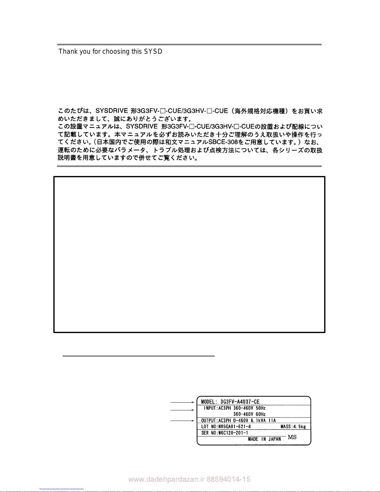
Items to Check when Unpacking
Check the following items when removing the product from the package:
S Has the correct product been delivered (i.e., the correct model number and speci-
fications)? Check the nameplate as shown below.
S Has the product been damaged in shipping?
S Are any screws or bolts loose?
Inverter model
Input specification
Output specification

www.dadehpardazan.ir 88594014-15
!
!
!
Notice:
OMRON products are manufactured for use according to proper procedures by a qualified operator
and only for the purposes described in this manual.
The following conventions are used to indicate and classify precautions in this manual. Always heed
the information provided with them. Failure to heed precautions can result in injury to people or damage to property.
DANGER Indicates an imminently hazardous situation which, if not avoided, will result in death or
serious injury.
WARNING Indicates a potentially hazardous situation which, if not avoided, could result in death or
serious injury.
Caution Indicates a potentially hazardous situation which, if not avoided, may result in minor or
moderate injury, or property damage.
OMRON Product References
All OMRON products are capitalized in this manual. The word “Unit” is also capitalized when it refers
to an OMRON product, regardless of whether or not it appears in the proper name of the product.
The abbreviation “Ch,” which appears in some displays and on some OMRON products, often means
“word” and is abbreviated “Wd” in documentation in this sense.
The abbreviation “PC” means Programmable Controller and is not used as an abbreviation for anything else.
Visual Aids
The following headings appear in the left column of the manual to help you locate different types of
information.
Note Indicates information of particular interest for efficient and convenient operation
of the product.
1. Indicates lists of one sort or another, such as procedures, checklists, etc.
OMRON, 2000
All rights reserved. No part of this publication may be reproduced, stored in a retrieval system, or transmitted, in any
form, or by any means, mechanical, electronic, photocopying, recording, or otherwise, without the prior written permission of OMRON.
No patent liability is assumed with respect to the use of the information contained herein. Moreover, because OMRON is
constantly striving to improve its high-quality products, the information contained in this manual is subject to change
without notice. Every precaution has been taken in the preparation of this manual. Nevertheless, OMRON assumes no
responsibility for errors or omissions. Neither is any liability assumed for damages resulting from the use of the information contained in this publication.

www.dadehpardazan.ir 88594014-15
!
!
!
!
!
!
!
!
!
!
!
!
Transportation Precautions
Caution Do not hold by front cover or panel , instead, hold by the radiation fin (heat sink) while
transporting the product. Doing so may result in injury.
Caution Do not pull on the cables. Doing so may result in damage to the product or malfunc-
tion.
Caution Use the eye-bolts only for transporting the Inverter. Using them for transporting the
machinery may result in injury or malfunction.
Installation Precautions
WARNING Provide an appropriate stopping device on the machine side to secure safety. (A
holding brake is not a stopping device for securing safety .) Not doing so may result in
injury.
WARNING Provide an external emergency stopping device that allows an instantaneous stop of
operation and power interruption. Not doing so may result in injury.
Caution Be sure to install the product in the correct direction and provide specified clear-
ances between the Inverter and control panel or with other devices. Not doing so
may result in fire or malfunction.
Caution Do not allow foreign objects to enter inside the product. Doing so may result in fire or
malfunction.
Caution Do not apply any strong impact. Doing so may result in damage to the product or
malfunction.
Wiring Precautions
WARNING Wiring must be performed only after confirming that the power supply has been
turned OFF. Not doing so may result in electrical shock.
WARNING Wiring must be performed by authorized personnel. Not doing so may result in
electrical shock or fire.
WARNING Be sure to confirm operation only after wiring the emergency stop circuit. Not doing
so may result in injury.
WARNING Always connect the ground terminals to a ground of 100 Ω or less for the 200-V AC
class, or 1 0 Ω or less for the 400-V AC class. Not connecting to a proper ground may
result in electrical shock.

www.dadehpardazan.ir 88594014-15
!
!
!
!
!
!
!
!
!
!
!
!
!
Caution Install external breakers and take other safety measures against short-circuiting in
external wiring. Not doing so may result in fire.
Caution Confirm that the rated input voltage of the Inverter is the same as the AC power sup-
ply voltage. An incorrect power supply may result in fire, injury, or malfunction.
Caution Connect the Braking Resistor and Braking Resistor Unit as specified in the manual.
Not doing so may result in fire.
Caution Be sure to wire correctly and securely. Not doing so may result in injury or damage t o
the product.
Caution Be sure to firmly tighten the screws on the terminal block. Not doing so may result in
fire, injury, or damage to the product.
Caution Do not connect an AC power to the U, V, or W output. Doing so may result in damage
to the product or malfunction.
Operation and Adjustment Precautions
WARNING Turn ON the input power supply only after mounting the front cover, terminal covers,
bottom cover, Operator, and optional items. Not doing so may result in electrical
shock.
WARNING Do not remove the front cover, terminal covers, bottom cover, Operator, or optional
items whi l e the power is being supplied. Not doing so may result in electrical shock or
damage to the product.
WARNING Do not operate the Operator or switches with wet hands. Doing so may result in
electrical shock.
WARNING Do not touch the inside of the Inverter. Doing so may result in electrical shock.
WARNING Do not come close to the machine when using the error retry function because the
machine may abruptly start when stopped by an alarm. Doing so may result in injury.
WARNING Do not come close to the machine immediately after resetting momentary power
interruption to avoid an unexpected restart (if operation is set to be continued in the
processing selection function after momentary power interruption is reset). Doing so
may result in injury.
WARNING Provide a separate emergency stop switch because the STOP Key on the Operator
is valid only when function settings are performed. Not doing so may result in injury.
www.dadehpardazan.ir 88594014-15
!
!
!
!
!
!
!
!
!
General Precautions
Observe the following precautions when using the SYSDRIVE Inverters and peripheral
devices.
This manual may include illustrations of the product with protective covers removed in order
to describe the components of the product in detail. Make sure that these protective covers
are on the product before use.
Consult your OMRON representative when using the product after a long period of storage.
WARNING Do not touch the inside of the Inverter. Doing so may result in electrical shock.
WARNING Operation, maintenance, or inspection must be performed after turning OFF the
power supply , confirming that the CHARGE indicator (or status indicators) are OFF,
and after waiting for the time specified on the front cover. Not doing s o may result in
electrical shock.
WARNING Do not damage, pull on, apply stress to, place heavy objects on, or pinch the cables.
Doing so may result in electrical shock.
WARNING Do not touch the rotating parts of the motor under operation. Doing so may result in
injury.
WARNING Do not modify the product. Doing so may result in injury or damage to the product.
Caution Do not store, install, or operate the product in the following places. Doing so may
result in electrical shock, fire or damage to the product.
S Locations subject to direct sunlight.
S Locations subject to temperatures or humidity outside the range specified in the
specifications.
S Locations subject to condensation as the result of severe changes in temperature.
S Locations subject to corrosive or flammable gases.
S Locations subject to exposure to combustibles.
S Locations subject to dust (especially iron dust) or salts.
S Locations subject to exposure to water, oil, or chemicals.
S Locations subject to shock or vibration.
Caution Do not touch the Inverter radiator, regenerative resistor, or Servomotor while the
power is being supplied or soon after the power is turned OFF. Doing so may result in
a skin burn due to the hot surface.
Caution Do not conduct a dielectric strength test on any part of the Inverter. Doing so may
result in damage to the product or malfunction.
Caution Take appropriate and sufficient countermeasures when installing systems in the fol-
lowing locations. Not doing so may result in equipment damage.
S Locations subject to static electricity or other forms of noise.
S Locations subject to strong electromagnetic fields and magnetic fields.
S Locations subject to possible exposure to radioactivity.
S Locations close to power supplies.

www.dadehpardazan.ir 88594014-15
!
!
!
!
!
!
!
!
!
!
!
WARNING Be sure confirm that the RUN signal is turned OFF before turning ON the power
supply, resetting the alarm, or switching the LOCAL/REMOTE selector. Doing so
while the RUN signal is turned ON may result in injury.
Caution Be sure to confirm permissible ranges of motors and machines before operation
because the Inverter speed can be easily changed from low to high. Not doing so
may result in damage to the product.
Caution Provide a separate holding brake when necessary. Not doing so may result in injury.
Caution Do not perform a signal check during operation. Doing so may result in injury or dam-
age to the product.
Caution Do not carelessly change settings. Doing so may result in injury or damage to the
product.
Maintenance and Inspection Precautions
WARNING Do not touch the Inverter terminals while the power is being supplied.
WARNING Maintenance or inspection must be performed only after turning OFF the power
supply, confirming that the CHARGE indicator (or status indicators) is turned OFF,
and after waiting for the time specified on the front cover. Not doing so may result in
electrical shock.
WARNING Maintenance, inspection, or parts replacement must be performed by authorized
personnel. Not doing so may result in electrical shock or injury.
WARNING Do not attempt to take the Unit apart or repair. Doing either of these may result in
electrical shock or injury.
Caution Carefully handle the Inverter because it uses semiconductor elements. Careless
handling may result in malfunction.
Caution Do not change wiring, disconnect connectors, the Operator, or optional items, or
replace fans while power is being supplied. Doing so may result in injury, damage to
the product, or malfunction.

www.dadehpardazan.ir 88594014-15
Warnings for UL/cUL Marking
- Do not connect or disconnect wiring, or perform signal checks while the power supply is turned ON.
- The Inverter internal capacitor is still charged even after the power supply is turned OFF . To prevent
electrical shock, disconnect all power before servicing the Inverter. Then wait at least one minute
after the power supply is disconnected and all indicators are OFF.
- Do not perform a withstand voltage test on any part of the Inverter. This electronic equipment uses
semiconductors and is vulnerable to high voltage.
- Do not remove the Digital Operator or the blank cover unless the power supply is turned OFF . Never
touch the printed control board (PCB) while the power supply is turned ON.
- The Inverter is not suitable for use on a circuit capable of delivering more than 5,000 RMS symmetrical amperes, 250 volts maximum (200-V-class Units) or 18,000 RMS symmetrical amperes, 480 V
maximum (400-V-class Units).
CAUTION
Separate motor overcurrent, overload and overheating protection is required to be provided in accordance with CANADIAN ELECTRICAL CODE, PART I and NEC.
Use 75°C copper wires or equivalent.
Low voltage wires shall be wired with Class I Wiring.
ATTENTION
Une protection distincte contre les surintensités, la surcharge et la surchauffé de moteur doit être
fournie conformément
AU CODE CANADIEN DE L’ELECTRICITE, PREMIER PARTIE et LE NATIONAL DE L’ELECTRI-
CITE.
Checking Before Unpacking
3G3FV-A4037-CUE
Specifications
Blank Japanese model
-E English model
-CE Conforms to EN Standards
-CUE Conforms to EN, UL/cUL Standards
Maximum motor capacity
004 0.4 kW
007 0.75 kW
015 1.5 kW
022 2.2 kW
037 3.7 kW
055 5.5 kW
075 7.5 kW
110 11 kW
150 15 kW
185 18.5 kW
220 22 kW
300 30 kW
370 37 kW
450 45 kW
550 55 kW
Voltage class
B Single-phase, 200 VAC (200-V model)
4 Three-phase, 400 VAC (400-V model)
Protective Structure
A Panel-mounting (IP10 min.) or closed
wall-mounting models
B Panel-mounting (IP00) models.
Series
3G3FV Series
3G3HV Series
www.dadehpardazan.ir 88594014-15
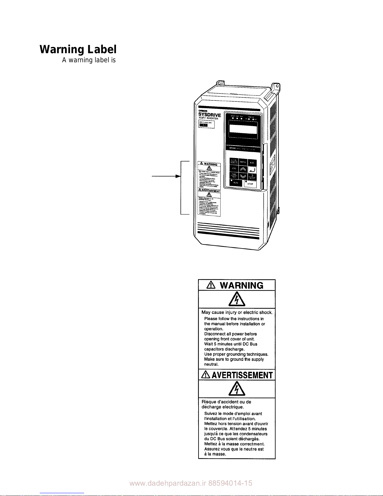
Warning Label
A warning label is attached to the product as shown in the following illustration. Be sure to
observe the precautionary items specified on the label.
Warning label
Contents of Warning Label

www.dadehpardazan.ir 88594014-15

www.dadehpardazan.ir 88594014-15
Table of Contents
Chapter 1. Introduction 1-1. . . . . . . . . . . . . . . . . . . . . . . . . . . . . . . . . . . . .
1-1 Function 1-2. . . . . . . . . . . . . . . . . . . . . . . . . . . . . . . . . . . . . . . . . . . . . . . . . . . . . . . . . . . . . . . . . . .
1-2 Nomenclature 1-5. . . . . . . . . . . . . . . . . . . . . . . . . . . . . . . . . . . . . . . . . . . . . . . . . . . . . . . . . . . . . . .
Chapter 2. Installation 2-1. . . . . . . . . . . . . . . . . . . . . . . . . . . . . . . . . . . . . .
2-1 Mounting 2-2. . . . . . . . . . . . . . . . . . . . . . . . . . . . . . . . . . . . . . . . . . . . . . . . . . . . . . . . . . . . . . . . . .
2-1-1 Dimensions 2-2. . . . . . . . . . . . . . . . . . . . . . . . . . . . . . . . . . . . . . . . . . . . . . . . . . . . . . . . . .
2-1-2 Installation Conditions 2-7. . . . . . . . . . . . . . . . . . . . . . . . . . . . . . . . . . . . . . . . . . . . . . . . .
2-2 Wiring 2-9. . . . . . . . . . . . . . . . . . . . . . . . . . . . . . . . . . . . . . . . . . . . . . . . . . . . . . . . . . . . . . . . . . . .
2-2-1 Removing and Mounting the Front Cover 2-10. . . . . . . . . . . . . . . . . . . . . . . . . . . . . . . . . .
2-2-2 Terminals 2-13. . . . . . . . . . . . . . . . . . . . . . . . . . . . . . . . . . . . . . . . . . . . . . . . . . . . . . . . . . . .
2-2-3 Standard Connection Diagram 2-18. . . . . . . . . . . . . . . . . . . . . . . . . . . . . . . . . . . . . . . . . . .
2-2-4 Wiring Around the Main Circuit 2-23. . . . . . . . . . . . . . . . . . . . . . . . . . . . . . . . . . . . . . . . .
2-2-5 Wiring Control Circuit Terminals 2-44. . . . . . . . . . . . . . . . . . . . . . . . . . . . . . . . . . . . . . . . .
Chapter 3. Specifications 3-1. . . . . . . . . . . . . . . . . . . . . . . . . . . . . . . . . . . .
3-1 Inverter Specifications 3-2. . . . . . . . . . . . . . . . . . . . . . . . . . . . . . . . . . . . . . . . . . . . . . . . . . . . . . . .
3-2 Input Noise Filter Specification 3-6. . . . . . . . . . . . . . . . . . . . . . . . . . . . . . . . . . . . . . . . . . . . . . . .
Revision History R-1. . . . . . . . . . . . . . . . . . . . . . . . . . . . . . . . .

www.dadehpardazan.ir 88594014-15

www.dadehpardazan.ir 88594014-15
Chapter 1
Introduction
1-1 Function
1-2 Nomenclature
1
www.dadehpardazan.ir 88594014-15
1-2
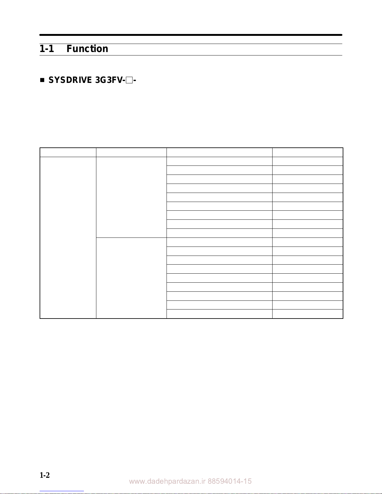
1-1 Function
H SYSDRIVE 3G3FV-j-CUE/3G3HV-j-CUE (-CE) Inverter Models
(Models Conforming to CE and UL/cUL Standards)
•SYSDRIVE Inverter models include the 3G3FV Series and 3G3HV Series that conform to the CE mark
and UL mark.
•The maximum applied motor capacity ranges from 0.4 kW to 160 kW (18 models).
D 3G3FV Series
Voltage class Protective structure Maximum applied motor capacity Model
400-V class NEMA1 type
0.4 kW 3G3FV-A4004-CUE
(3-phase)
0.75 kW 3G3FV-A4007-CUE
1.5 kW 3G3FV-A4015-CUE
2.2 kW 3G3FV-A4022-CUE
3.7 kW 3G3FV-A4037-CUE
5.5 kW 3G3FV-A4055-CUE
7.5 kW 3G3FV-A4075-CUE
11 kW 3G3FV-A4110-CUE
15 kW 3G3FV-A4150-CUE
Open chassis type
18.5 kW 3G3FV-B4185-CUE
22 kW 3G3FV-B4220-CUE
30 kW 3G3FV-B4300-CUE
37 kW 3G3FV-B4370-CUE
45 kW 3G3FV-B4450-CUE
55 kW 3G3FV-B4550-CUE
75 kW 3G3FV-B4750-CUE
110 kW 3G3FV-B411K-CUE
160 kW 3G3FV-B416K-CUE
Introduction Chapter 1
www.dadehpardazan.ir 88594014-15
1-3
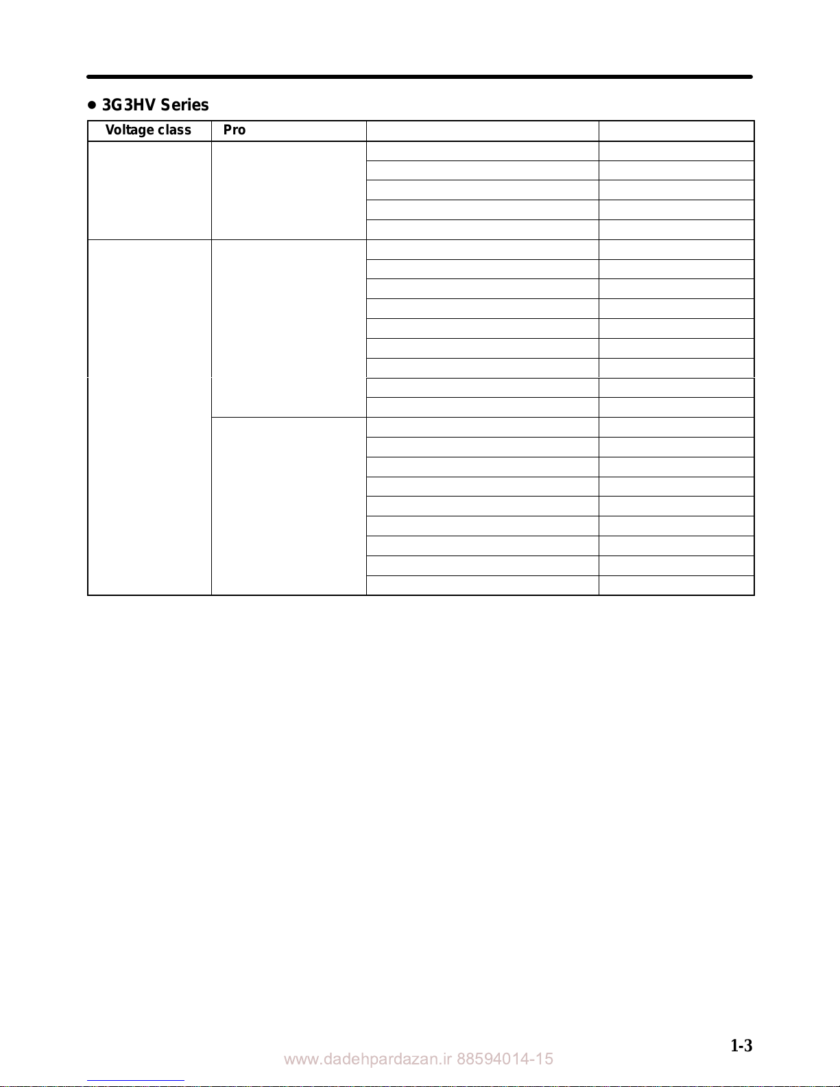
D 3G3HV Series
Voltage class Protective structure Maximum applied motor capacity Model
200-V class NEMA1 type
0.4 kW 3G3HV-AB004-CE
(single phase)
0.75 kW 3G3HV-AB007-CE
1.5 kW 3G3HV-AB015-CE
2.2 kW 3G3HV-AB022-CE
3.7 kW 3G3HV-AB037-CE
400-V class NEMA1 type
0.4 kW 3G3HV-A4004-CUE
(3-phase)
0.75 kW 3G3HV-A4007-CUE
1.5 kW 3G3HV-A4015-CUE
2.2 kW 3G3HV-A4022-CUE
3.7 kW 3G3HV-A4037-CUE
5.5 kW 3G3HV-A4055-CUE
7.5 kW 3G3HV-A4075-CUE
11 kW 3G3HV-A4110-CUE
15 kW 3G3HV-A4150-CUE
Open chassis type
18.5 kW 3G3HV-B4185-CUE
22 kW 3G3HV-B4220-CUE
30 kW 3G3HV-B4300-CUE
37 kW 3G3HV-B4370-CUE
45 kW 3G3HV-B4450-CUE
55 kW 3G3HV-B4550-CUE
75 kW 3G3HV-B4750-CUE
110 kW 3G3HV-B411K-CUE
160 kW 3G3HV-B416K-CUE
H Conformance to the LVD (Low-voltage Directives) and EMC Directives
The SYSDRIVE CUE (CE) models conform to the LVD (prEN50178) and the EMC (EN50081-2,
EN50082-2) Directives.
However, when the product is built into a unit, the connected switches, optional items, or motors may not
satisfy these standards. In such a case, either use components that meet the standards or take appropriate countermeasures such as providing surge killers or other noise prevention devices.
H Conformance Conditions
There are several conditions that must be satisfied for this Inverter to conform to the LVD and EMC
Directives. To satisfy the standards, meet the instructions in this manual for the following installation
conditions. If the Inverters are used beyond the conditions specified here, final confirmation must be
made on the overall units.
•Installation of noise filters.
•Shield stranded cables must be used for input and output cables.
Limitations on the lengths of cables.
•Installation of metallic ground plates.
•Installation of recommended fuses on the input side.
Introduction Chapter 1

www.dadehpardazan.ir 88594014-15
1-4
H UL/cUL Standards
SYSDRIVE models described here as “Models Conforming to CE and UL/cUL Standards” have obtained approval on the UL/cUL Standard (UL508C) in addition to the EC Directives. The SYSDRIVE
models meeting these standards can be used worldwide.
H Other Functions
Although this manual describes the installation methods for conforming to the LVD and EMC Directives,
it does not describe the standard functions of the Inverter. For details, please refer to the User’s Manual
for each Series.
•3G3FV Series: SYSDRIVE 3G3FV High-function General-purpose Inverter (I516-E1)
•3G3HV Series: SYSDRIVE 3G3HV High-capacity General-purpose Inverter (I515-E1)
Introduction Chapter 1
www.dadehpardazan.ir 88594014-15
1-5
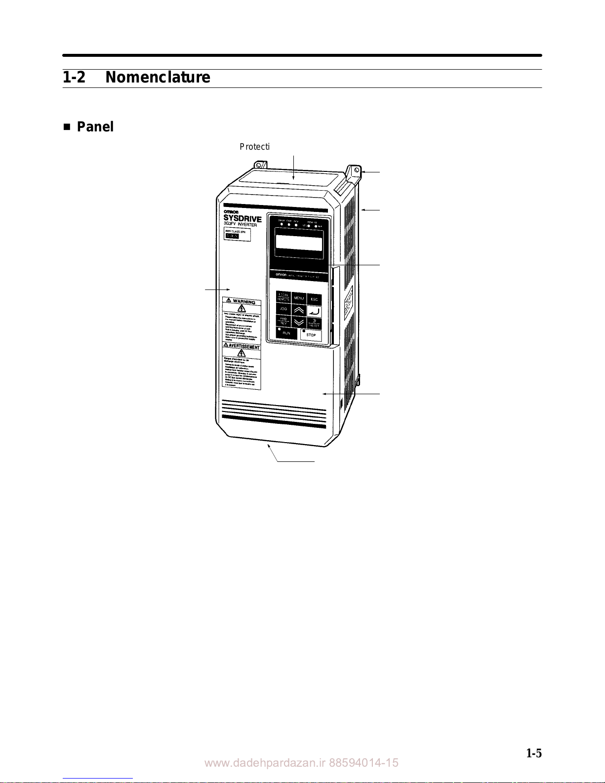
1-2 Nomenclature
H Panel
Protection cover (top and bottom)
Mounting hole
Heat sink
Digital Operator
Front cover
Terminals
Front cover fixing bracket
3G3FV Series
Introduction Chapter 1
www.dadehpardazan.ir 88594014-15
1-6
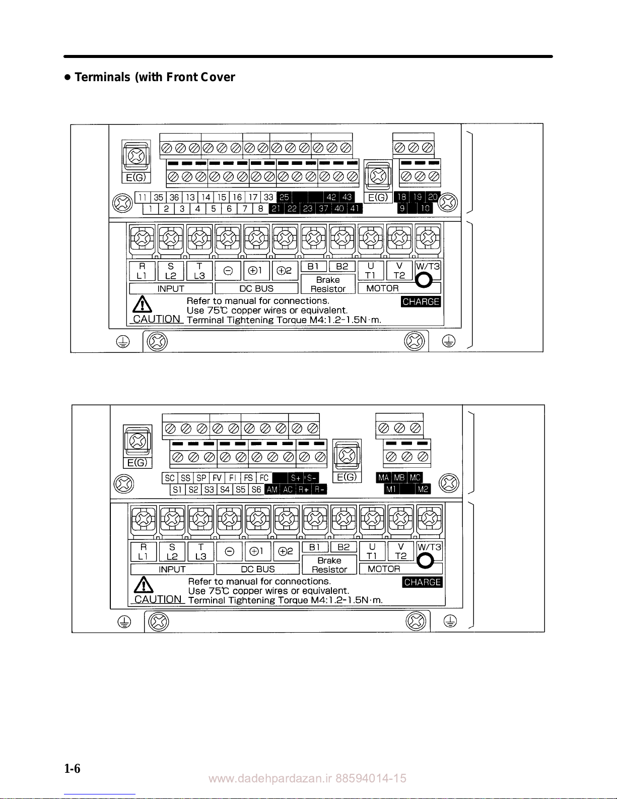
D Terminals (with Front Cover Removed)
3G3FV Series: 400-V Class Inverter with 3.7-kW Output
Control
circuit
terminals
Main circuit
terminals
3G3HV Series: 400-V Class Inverter with 3.7-kW Output
Control
circuit
terminals
Main circuit
terminals
Introduction Chapter 1
www.dadehpardazan.ir 88594014-15
Chapter 2
Installation
2-1 Mounting
2-2 Wiring
2
www.dadehpardazan.ir 88594014-15
2-2
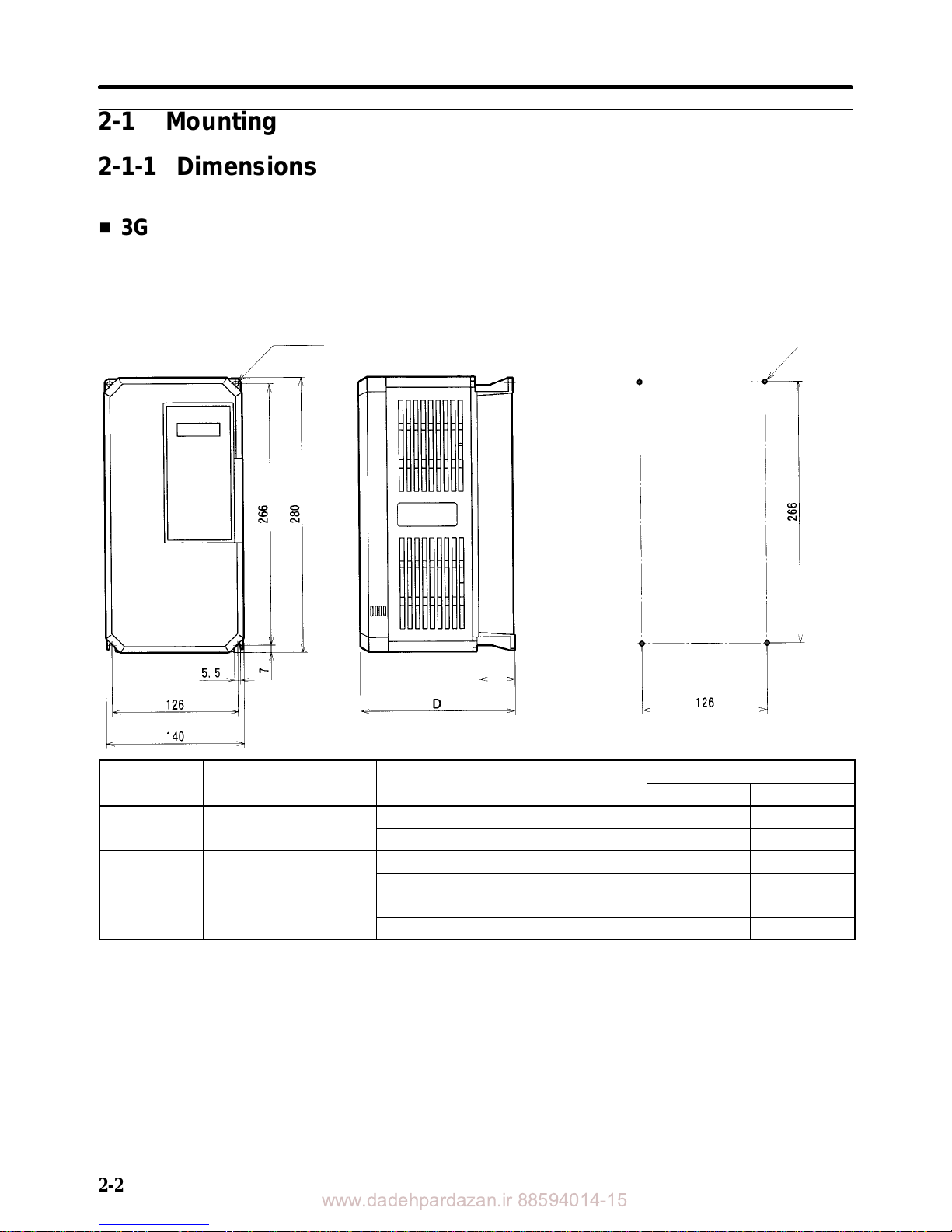
2-1 Mounting
2-1-1 Dimensions
H 3G3FV-A4004-CUE/-A4007-CUE/-A4015-CUE/-A4022-CUE/-A4037-CUE
3G3HV-AB004-CE/-AB007-CE/-AB015-CE/-A4004-CUE/-A4007-CUE
3G3HV-A4015-CUE/-A4022-CUE/-A4037-CUE
D External Dimensions D Mounting Dimensions
Two, 5.5 dia.
Four, M5
D2
Series Voltage class Model 3G3FV-/3G3HV-
Dimensions (mm)
D D2
3G3FV 400-V
A4004-CUE/A4007-CUE 160 39
A4015-CUE/A4022-CUE/A4037-CUE 180 59
3G3HV 200-V (single phase)
AB004-CE 160 39
AB007-CE/AB015-CE 180 59
400-V
A4004-CUE/A4007-CUE 160 39
A4015-CUE/A4022-CUE/A4037-CUE 180 59
Installation Chapter 2
www.dadehpardazan.ir 88594014-15
2-3
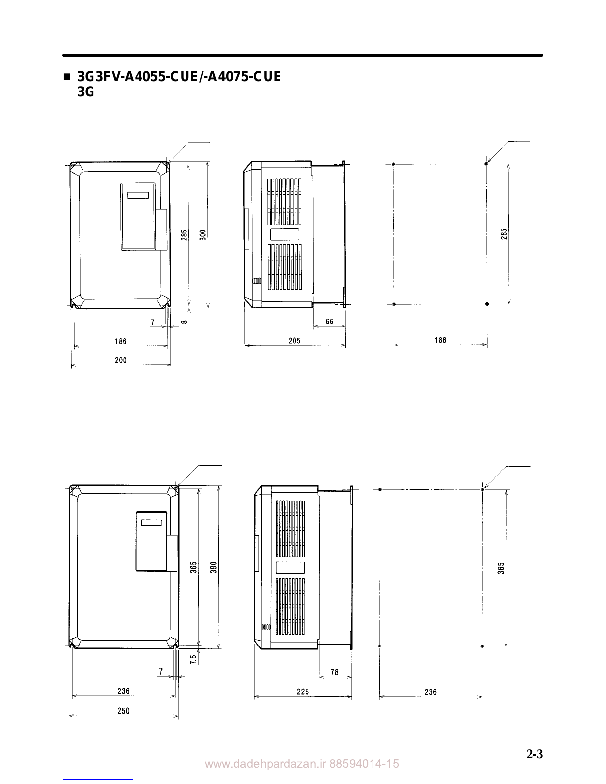
H 3G3FV-A4055-CUE/-A4075-CUE
3G3HV-AB022-CE/-AB037-CE/-A4055-CUE/-A4075-CUE
D External Dimensions D Mounting Dimensions
Two, 7 dia.
Four, M6
H 3G3FV-A4110-CUE/-A4150-CUE
3G3HV-A4110-CUE/-A4150-CUE
D External Dimensions D Mounting Dimensions
Two, 7 dia.
Four, M6
Installation Chapter 2
www.dadehpardazan.ir 88594014-15
2-4
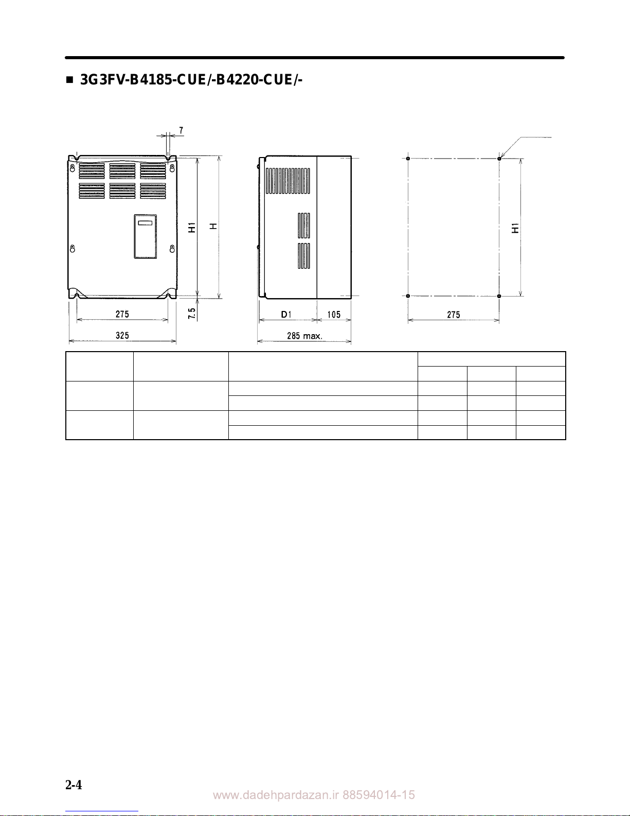
H 3G3FV-B4185-CUE/-B4220-CUE/-B4300-CUE/-B4450-CUE
3G3HV-B4185-CUE/-B4220-CUE/-B4300-CUE/-B4450-CUE
D External Dimensions D Mounting Dimensions
Four, M6
Series Voltage class Model 3G3FV-/3G3HV-
Dimensions (mm)
H H1 D1
3G3FV 400-V
B4185-CUE/B4220-CUE 450 435 174.5
B4300-CUE/B4370-CUE/B4450-CUE 625 610 175
3G3HV 400-V
B4185-CUE/B4220-CUE 450 435 174.5
B4300-CUE/B4370-CUE/B4450-CUE 625 610 175
Installation Chapter 2
www.dadehpardazan.ir 88594014-15
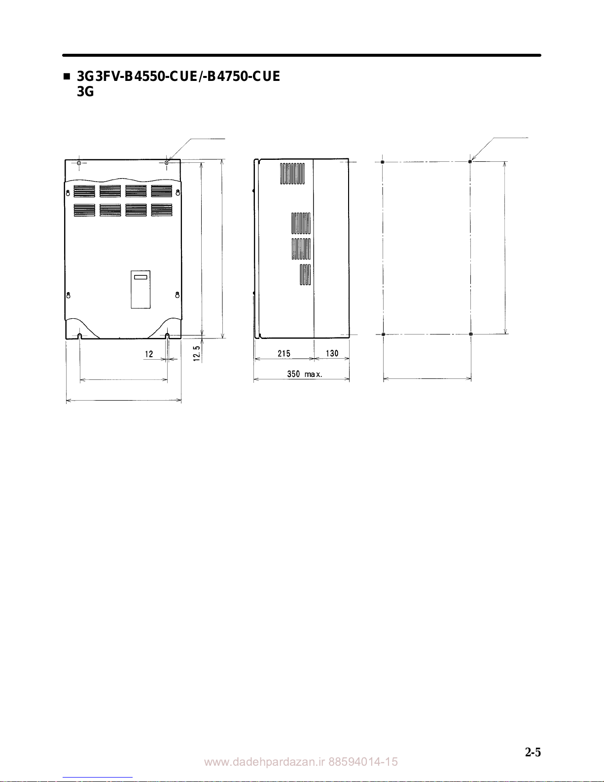
2-5
H 3G3FV-B4550-CUE/-B4750-CUE
3G3HV-B4550-CUE/-B4750-CUE
D External Dimensions D Mounting Dimensions
Two, 12 dia.
Four, M10
350
455
350
795
820
795
Installation Chapter 2
 Loading...