

Page 1

=;76HULHV
&DW1R,((1$
<5&;5RERW&RQWUROOHU
352*5$00,1*
0$18$/
6&$5$5RERWV
<5&;6HULHV
Page 2

Page 3

Introduction
Our sincere thanks for your purchase of this OMRON YRCX robot controller.
This manual describes robot program commands and related information for using OMRON YRCX
robot controllers. Be sure to read this manual carefully as well as related manuals and comply with
their instructions for using the OMRON robot controllers safely and correctly.
For details on how to operate OMRON robot controllers, refer to the separate controller user's
manual that comes with the OMRON robot controller.
Applicable controllers:
YRCX
Page 4
Safety precautions
Be sure to read before using
Before using the OMRON robot controller, be sure to read this manual and related manuals, and
follow their instructions to use the robot controller safely and correctly.
Warning and caution items listed in this manual relate to OMRON robot controllers.
When this robot controller is used in a robot controller system, please take appropriate safety
measures as required by the user’s individual system.
This manual classifies safety caution items and operating points into the following levels, along with
symbols for signal words “CAUTION” and “NOTE”.
CAUTION
"CAUTION" indicates a potentially hazardous situation which, if not avoided, could
result in minor or moderate injury or damage to the equipment or software.
NOTE
Primarily explains function differences, etc., between software versions.
MEMO
Explains robot operation procedures in a simple and clear manner.
Note that the items classified into “CAUTION” might result in serious injury depending on the
situation or environmental conditions.
Keep this manual carefully so that the operator can refer to it when needed. Also make sure that this
manual reaches the end user.
Page 5

CONTENTS
Programming Manual
Introduction
Safety precautions
Chapter 1 Writing Programs
1 The OMRON Robot Language 1-1
2 Characters 1-1
3 Program Basics 1-1
4 Program Names 1-2
5 Identiers 1-4
6 LABELStatement 1-4
YRCX
7 Comment 1-5
8 Command Statement Format 1-5
Chapter 2 Constants
1 Outline 2-1
2 Numeric constants 2-1
2.1 Integer constants 2-1
2.2 Real constants 2-1
3 Character constants 2-2
Chapter 3 Variables
1 Outline 3-1
2 User Variables & System Variables 3-2
2.1 User Variables 3-2
2.2 System Variables 3-2
3 Variable Names 3-3
3.1 Dynamic Variable Names 3-3
3.2 Static Variable Names 3-3
4 VariableTypes 3-4
T-1
Page 6

CONTENTS
4.1 Numeric variables 3-4
4.2 Character variables 3-4
5 Array variables 3-5
6 Value Assignments 3-5
7 Type Conversions 3-6
8 Value Pass-Along & Reference Pass-Along 3-6
9 System Variables 3-7
9.1 Point variable 3-7
9.2 Shift variable 3-8
9.3 Parallel input variable 3-8
9.4 Parallel output variable 3-9
9.5 Internal output variable 3-10
9.6 Arm lock output variable 3-11
9.7 Timer output variable 3-12
9.8 Serial input variable 3-13
9.9 Serial output variable 3-14
9.10 Serial word input 3-15
9.11 Serial double word input 3-15
9.12 Serial word output 3-16
9.13 Serial double word output 3-16
Programming Manual
YRCX
T-2
10 Bit Settings 3-17
11 Valid range of variables 3-18
11.1 Valid range of dynamic (array) variables 3-18
11.2 Valid range of static variables 3-18
Clearing variables 3-19
12
12.1 Clearing dynamic variables 3-19
12.2 Clearing static variables 3-19
Chapter4 ExpressionsandOperations
1 Arithmeticoperations 4-1
1.1 Arithmetic operators 4-1
1.2 Relational operators 4-1
1.3 Logic operations 4-2
1.4 Priority of arithmetic operation 4-3
1.5 Data format conversion 4-3
Page 7

CONTENTS
2 Characterstringoperations 4-4
2.1 Character string connection 4-4
2.2 Character string comparison 4-4
3 Pointdataformat 4-5
4 DI/DOconditionalexpressions 4-6
Programming Manual
Chapter 5 Multiple Robot Control
1 Overview 5-1
2 Command list with a robot setting 5-2
Chapter 6 Multi-tasking
1 Outline 6-1
YRCX
2 Taskdenitionmethod 6-1
3 Task status and transition 6-2
3.1 Starting tasks 6-2
3.2 Task scheduling 6-3
3.3 Condition wait in task 6-4
3.4 Suspending tasks (SUSPEND) 6-5
3.5 Restarting tasks (RESTART) 6-5
3.6 Deleting tasks 6-6
3.7 Stopping tasks 6-7
4 Multi-taskprogramexample 6-8
5 Sharing the data 6-8
6 Cautionary Items 6-9
Chapter 7 Sequence fnction
1 Sequence function 7-1
2 Creating a sequence program 7-1
2.1 Programming method 7-1
2.2 Compiling 7-3
3 Executingasequenceprogram 7-4
3.1 Sequence program STEP execution 7-4
T-3
Page 8

CONTENTS
4 Programming a sequence program 7-5
4.1 Assignment statements 7-5
4.2 Input/output variables 7-5
4.2.1 Input variables 7-5
4.2.2 Output variables 7-6
4.3 Timerdenitionstatement 7-7
4.4 Logical operators 7-7
4.5 Priority of logic operations 7-8
4.6 Sequenceprogramspecications 7-8
Chapter 8 Robot Language Lists
How to read the robot language table 8-1
Command list in alphabetic order 8-2
Operation-specic 8-7
Programming Manual
YRCX
Functions: in alphabetic order 8-13
Functions:operation-specic 8-16
1 ABS
2 ABSRPOS
3 ACCEL
4 ARCHP1 / ARCHP2
5 ARMCND
6 ARMSEL
7 ARMTYP
8 ASPEED
9 ATN / ATN2
10 AXWGHT
11 CALL
12 CHANGE
13 CHGPRI
14 CHR$
15 CLOSE
16 COS
17 CURTQST
Acquires absolute values 8-18
Acquires the machine reference value (axes: mark method) 8-19
Species/acquires the acceleration coefcient parameter 8-20
Species/acquires the arch position parameter 8-21
Acquires the current arm status 8-23
Sets/acquires the current hand system selection 8-24
Sets/acquires the hand system selection during program reset 8-25
Sets/acquires the AUTO movement speed of a specied robot 8-26
Acquires the arctangent of the specied value 8-27
Sets/acquires the axis tip weight 8-28
Calls a sub-procedure 8-29
Switches the hand 8-30
Changes the priority ranking of a specied task 8-31
Acquires a character with the specied character code 8-32
Closes the specied General Ethernet Port 8-33
Acquires the cosine value of a specied value 8-34
Acquires the current torque value of a specied axis
to the rated torque 8-35
T-4
18 CURTRQ
Acquires the current torque of the specied axis 8-36
Page 9

CONTENTS
Programming Manual
YRCX
19 CUT
20 DATE$
21 DECEL
22 DEF FN
23 DEGRAD
24 DELAY
25 DI
26 DIM
27 DIST
28 DO
29 DRIVE
30 DRIVEI
31 END SELECT
32 END SUB
33 ERR / ERL
34 ETHSTS
35 EXIT FOR
36 EXIT SUB
Terminates another task which is currently being executed 8-37
Acquires the date 8-38
Species/acquires the deceleration rate parameter 8-39
Denes functions which can be used by the user 8-40
Angle conversion (degree → radian) 8-41
Program execution waits for a specied period of time 8-42
Acquires the input status from the parallel port 8-43
Declares array variable 8-44
Acquires the distance between 2 specied points 8-45
Outputs to parallel port or acquires the output status 8-46
Executes absolute movement of specied axes 8-48
Moves the specied robot axes in a relative manner 8-52
Ends the SELECT CASE statement 8-57
Ends the sub-procedure denition 8-58
Acquires the error code / error line number 8-59
Acquires the Ethernet port status 8-60
Terminates the FOR to NEXT statement loop 8-61
Terminates the sub-procedure dened by the SUB to END SUB
statement 8-62
37 EXIT TASK
38 FOR to NEXT
39 GEPSTS
40 GOSUB to RETURN
41 GOTO
42 HALT
43 HALTALL
44 HAND
44.1 For SCARA Robots 8-70
45 HOLD
46 HOLDALL
47 IF
47.1 Simple IF statement 8-75
47.2 Block IF statement 8-76
48 INPUT
49 INT
Terminates its own task which is in progress 8-63
Performs loop processing until the variable exceeds
the specied value 8-64
Acquires the General Ethernet Port status 8-65
Jumps to a subroutine 8-66
Executes an unconditional jump to the specied line 8-67
Stops the program and performs a reset 8-68
Stops all programs and performs reset 8-69
Denes the hand 8-70
Temporarily stops the program 8-73
Temporality stops all programs 8-74
Evaluates a conditional expression value, and executes
the command in accordance with the conditions 8-75
Assigns a value to a variable specied from the programming box 8-77
Truncates decimal fractions 8-79
T-5
Page 10

CONTENTS
Programming Manual
YRCX
50 JTOXY
51 LEFT$
52 LEFTY
53 LEN
54 LET
55 LO
56 LOCx
57 LSHIFT
58 MCHREF
59 MID$
60 MO
61 MOTOR
62 MOVE
63 MOVEI
64 MOVET
65 MTRDUTY
66 OFFLINE
67 ON ERROR GOTO
68 ON to GOSUB
69 ON to GOTO
70 ONLINE
71 OPEN
72 ORD
73 ORGORD
74 ORIGIN
75 OUT
76 OUTPOS
77 PATH
78 PATH END
79 PATH SET
80 PATH START
81 PDEF
82 PGMTSK
Performs axis unit system conversions (pulse → mm) 8-80
Extracts character strings from the left end 8-81
Sets the SCARA robot hand system as a left-handed system 8-82
Acquires a character string length 8-83
Assigns values to variables 8-84
Arm lock output or acquires the output status 8-87
Species/acquires point data for a specied axis or shift data
for a specied element 8-89
Left-shifts a bit 8-91
Acquires the machine reference value
(axes: sensor method / stroke-end method) 8-92
Acquires a character string from a specied position 8-93
Outputs a specied value to the MO port
or acquires the output status 8-94
Controls the motor power status 8-96
Performs absolute movement of robot axes 8-97
Performs relative movement of robot axes 8-112
Performs relative movement of all robot axes in tool coordinates 8-122
Acquires the motor load factor of the specied axis 8-132
Sets a specied communication port to the "ofine" mode 8-133
Jumps to a specied label when an error occurs 8-134
Executes the subroutine specied by the <expression> value 8-135
Jumps to the label specied by the <expression> value 8-136
Sets the specied communication port to the "online" mode 8-137
Opens the specied General Ethernet Port 8-138
Acquires a character code 8-139
Species/acquires the robot's return-to-origin sequence 8-140
Performs return-to-origin 8-141
Turns ON the specied port output 8-142
Species/acquires the OUT enable position parameter of the robot
Species the motion path 8-145
Ends the path setting 8-151
Starts the path setting 8-152
Starts the PATH motion 8-155
Denes the pallet 8-159
Acquires the task number
in which a specied program is registered 8-160
8-143
T-6
Page 11

CONTENTS
Programming Manual
YRCX
83 PGN
84 PMOVE
85 Pn
86 PPNT
87 PRINT
88 PSHFRC
89 PSHJGSP
90 PSHMTD
91 PSHRSLT
92 PSHSPD
93 PSHTIME
94 PUSH
95 RADDEG
96 REM
97 RESET
98 RESTART
99 RESUME
RETURN
100
Acquires the program number from a specied program name 8-161
Executes a pallet movement command for the robot 8-162
Denes points within a program 8-166
Creates pallet point data 8-168
Displays the specied expression value at the programming box 8-169
Species/acquires the pushing force parameter 8-170
Species/acquires the push judge speed parameter 8-171
Species/acquires a pushing type parameter 8-172
Acquires the status when PUSH statement ends 8-173
Species/acquires the push speed parameter 8-174
Species/acquires the push time parameter 8-175
Executes a pushing operation for specied axes 8-176
Performs a unit conversion (radians → degrees) 8-181
Inserts a comment 8-182
Turns OFF the bits of specied ports, or clears variables 8-183
Restarts another task during a temporary stop 8-184
Resumes program execution after error recovery processing 8-185
Processing which was branched by GOSUB, is returned
to the next line after GOSUB 8-186
RIGHT$
101
RIGHTY
102
RSHIFT
103
104
SELECT CASE to END SELECT
SEND
105
SERVO
106
SET
107
SETGEP
108
SGI
109
SGR
110
SHARED
111
SHIFT
112
SI
113
SID
114
SIN
115
Extracts a character string
from the right end of another character string 8-187
Sets the SCARA robot hand system as a right-handed system 8-188
Shifts a bit value to the right 8-189
Executes the specied command block in accordance with the
<expression> value 8-190
Sends readout le data to the write le 8-191
Controls the servo status 8-193
Turns the bit at the specied output port ON 8-194
Sets the General Ethernet Port 8-195
Assigns /acquires the value
to a specied integer type static variable 8-196
Assigns /acquires the value to a specied real type static variable
Enables sub-procedure referencing without passing on the variable
Sets the shift coordinates 8-199
Acquires specied SI status 8-200
Acquires a specied serial input's double-word information 8-201
Acquires the sine value for a specied value 8-202
8-197
8-198
T-7
Page 12

CONTENTS
Programming Manual
YRCX
SIW
116
Sn
117
SO
118
SOD
119
SOW
120
SPEED
121
SQR
122
START
123
STR$
124
SUB to END SUB
125
SUSPEND
126
SWI
127
TAN
128
TCOUNTER
129
TIME$
130
TIMER
131
TO
132
Acquires a specied serial input's word information 8-203
Denes the shift coordinates in the program 8-204
Outputs a specied value
to serial port or acquires the output status 8-205
Outputs a specied serial output's double-word information
or acquires the output status 8-207
Outputs a specied serial output's word information
or acquires the output status 8-208
Changes the program movement speed 8-209
Acquires the square root of a specied value 8-210
Starts a new task 8-211
Converts a numeric value to a character string 8-212
Denes a sub-procedure 8-213
Temporarily stops another task which is being executed 8-215
Switches the program being executed 8-216
Acquires the tangent value for a specied value 8-217
Timer & counter 8-218
Acquires the current time 8-219
Acquires the current time 8-220
Outputs a specied value to the TO port
or acquires the output status 8-221
TOLE
133
TORQUE
134
TSKPGM
135
VAL
136
WAIT
137
WAIT ARM
138
WEIGHT
139
WEND
140
WHERE
141
WHILE to WEND
142
WHRXY
143
XYTOJ
144
Species/acquires the tolerance parameter 8-222
Species/acquires the maximum torque command value 8-223
Acquires the program number
which is registered in a specied task number 8-225
Converts character strings to numeric values 8-226
Waits until the conditional expression is met 8-227
Waits until the robot axis operation is completed 8-228
Species/acquires the tip weight parameter 8-229
Ends the WHILE statement's command block 8-230
Acquires the arm's current position (pulse coordinates) 8-231
Repeats an operation for as long as a condition is met 8-232
Acquires the arm's current position in Cartesian coordinates 8-233
Converts the Cartesian coordinate data ("mm")
to joint coordinate data ("pulse") 8-234
T-8
Page 13

CONTENTS
Programming Manual
Chapter 9 PATH Statements
1 Overview 9-1
2 Fe atur e s 9 -1
3 How to use 9-1
4 Cautions when using this function 9-2
Chapter10Dataledescription
1 Overview 10-1
1.1 Dataletypes 10-1
1.2 Cautions 10-2
2 Programle 10-3
YRCX
2.1 All programs 10-3
2.2 One program 10-4
3 Pointle 10-5
3.1 All points 10-5
3.2 One point 10-7
4 Pointcommentle 10-8
4.1 All point comments 10-8
4.2 One point comment 10-9
5 Pointnamele 10-10
5.1 All point names 10-10
5.2 One point name 10-11
6 Parameterle 10-12
6.1 All parameters 10-12
6.2 One parameter 10-14
7 Shiftcoordinatedenitionle 10-16
7.1 All shift data 10-16
7.2 Oneshiftdenition 10-17
8 Handdenitionle 10-18
8.1 All hand data 10-18
8.2 Onehanddenition 10-19
T-9
Page 14

CONTENTS
9 Palletdenitionle 10-20
9.1 Allpalletdenitions 10-20
9.2 Onepalletdenition 10-22
10 GeneralEthernetportle 10-24
11 Input/outputnamele 10-26
11.1 All input/output name data 10-26
11.2 One input/output type 10-27
11.3 One input/output port 10-28
11.4 One input/output bit 10-29
Areacheckoutputle 10-30
12
12.1 All area check output data 10-30
12.2 Oneareacheckoutputdenition 10-31
13 Allle 10-32
Programming Manual
YRCX
13.1 Allle 10-32
14 Programdirectoryle 10-34
14.1 Entire program directory 10-34
14.2 One program directory 10-35
15 Parameterdirectoryle 10-36
15.1 Entire parameter directory 10-36
16 Machinereferencele 10-37
16.1 Machine reference (axes: sensor method, stroke-end method) 10-37
16.2 Machine reference (axes: mark method) 10-38
17 Systemcongurationinformationle 10-39
18 Versioninformationle 10-40
19 Optionboardle 10-41
20 Selfcheckle 10-42
T-10
21 Alarmhistoryle 10-43
22 Remainingmemorysizele 10-45
23 Variablele 10-46
Page 15

CONTENTS
Programming Manual
24 Constantle 10-52
24.1 One character string 10-52
25 Arrayvariablele 10-53
25.1 All array variables 10-53
25.2 One array variable 10-54
26 DIle 10-55
26.1 All DI information 10-55
26.2 One DI port 10-56
27 DOle 10-57
27.1 All DO information 10-57
27.2 One DO port 10-58
28 MOle 10-59
28.1 All MO information 10-59
28.2 One MO port 10-60
YRCX
29 LOle 10-61
29.1 All LO information 10-61
29.2 One LO port 10-62
30 TOle 10-63
30.1 All TO information 10-63
30.2 One TO port 10-64
31 SIle 10-65
31.1 All SI information 10-65
31.2 One SI port 10-66
32 SOle 10-67
32.1 All SO information 10-67
32.2 One SO port 10-68
33 SIWle 10-69
33.1 All SIW data 10-69
33.2 One SIW data 10-70
34 SOWle 10-71
34.1 All SOW 10-71
34.2 One SOW data 10-72
T-11
Page 16

CONTENTS
35 EOFle 10-73
35.1 EOF data 10-73
36 Serialportcommunicationle 10-74
36.1 Serialportcommunicationle 10-74
37 Ethernetportcommunicationle 10-75
37.1 Ethernetportcommunicationle 10-75
Chapter11Userprogramexamples
1 Basic operation 11-1
1.1 Directly writing point data in program 11-1
1.2 Using point numbers 11-2
1.3 Using shift coordinates 11-3
1.4 Palletizing 11-4
1.4.1 Calculating point coordinates 11-4
1.4.2 Utilizing pallet movement 11-6
1.5 DI/DO (digital input and output) operation 11-7
Programming Manual
YRCX
2 Application 11-8
2.1 Pick and place between 2 points 11-8
2.2 Palletizing 11-10
2.3 Pick and place of stacked parts 11-12
2.4 Parts inspection (Multi-tasking example) 11-14
2.5 Sealing 11-17
2.6 Connection to an external device through RS-232C (example 1) 11-18
2.7 Connection to an external device through RS-232C (example 2) 11-19
Chapter 12 Online commands
1 Online Command List 12-1
1.1 Onlinecommandlist:Operation-specic 12-2
1.2 Online command list: In alphabetic order 12-6
2 Operation and setting commands 12-9
2.1 Program operations 12-9
2.2 MANUAL mode operation 12-17
2.3 Alarm reset 12-18
2.4 Clearingoutputmessagebuer 12-19
2.5 Setting input data 12-20
2.6 Change access level 12-21
2.7 Setting input data 12-22
T-12
Page 17

CONTENTS
Programming Manual
3 Reference commands 12-23
3.1 Acquiring return-to-origin status 12-23
3.2 Acquiring the servo status 12-24
3.3 Acquire motor power status 12-24
3.4 Acquiring the access level 12-25
3.5 Acquiring the break point status 12-25
3.6 Acquiring the mode status 12-26
3.7 Acquiring the communication port status 12-26
3.8 Acquiring the main program number 12-27
3.9 Acquiring the sequence program execution status 12-27
3.10 Acquiring the version information 12-28
3.11 Acquiring the tasks in RUN or SUSPEND status 12-28
3.12 Acquiring the tasks operation status 12-29
3.13 Acquiring the task end condition 12-29
3.14 Acquiring the shift status 12-30
3.15 Acquiring the hand status 12-30
3.16 Acquiring the remaining memory capacity 12-31
3.17 Acquiring the alarm status 12-31
3.18 Acquiring the emergency stop status 12-32
3.19 Acquiring the manual movement speed 12-32
3.20 Acquiring the inching movement amount 12-33
3.21
Acquiring the last reference point number (current point number) 12-33
3.22 Acquiring the output message 12-34
3.23 Acquiring the input data 12-34
3.24 Acquiring various values 12-35
YRCX
4 Operation commands 12-37
4.1 Absolute reset 12-37
4.2 Return-to-origin operation 12-38
4.3 Manual movement: inching 12-39
4.4 Manual movement: jog 12-40
5 Dataleoperationcommands 12-41
5.1 Copy operations 12-41
5.2 Erase 12-42
5.3 Rename program 12-47
5.4 Changing the program attribute 12-47
5.5 Initialization process 12-48
5.6 Data readout processing 12-50
5.7 Data write processing 12-51
T-13
Page 18

CONTENTS
6 Utility commands 12-52
6.1 Settingthesequenceprogramexecutionag 12-52
6.2 Setting the date 12-52
6.3 Setting the time 12-53
7 Individualexecutionofrobotlanguage 12-54
8 Control codes 12-55
Chapter13Appendix
1 Reserved word list 13-1
2 Changes from conventional models 13-3
1 Program name 13-3
A) FUNCTION 13-3
B) _SELECT 13-3
2 Multiple Robot Control 13-3
3 Multi-tasking 13-4
4 Robot Language 13-4
5 Online commands 13-5
6 Datale 13-5
Programming Manual
YRCX
Index
T-14
Page 19

Chapter 1
Writing Programs
1 1
The OMRON Robot Language .................
2 2
Characters ................................................
3 3
Program Basics .........................................
4 4
Program Names ........................................
5 5
Identifiers ...................................................
6 6
LABEL Statement .......................................
7 7
Comment ..................................................
8 8
Command Statement Format .................
1-1
1-1
1-1
1-2
1-4
1-4
1-5
1-5
Page 20

Page 21
1
The OMRON Robot Language
1
The OMRON robot language is similar to BASIC (Beginner’s All-purpose Symbolic Instruction Code)
and makes even complex robot movements easy to program. This manual explains how to write
robot control programs with the OMRON robot language, including actual examples on how its
commands are used.
2
Characters
2
3
The characters and symbols used in the OMRON robot language are shown below.
Only 1-byte characters can be used.
• Alphabetic characters
A to Z, a to z
• Numbers
0 to 9
• Symbols
( ) [ ] + - * / ^ = < > & | ~ _ % ! # $ : ; , . " ' { }@ ?
• katakana (Japanese phonetic characters
)
4
5
MEMO
3
• For details regarding sub-
• For details regarding user
Program Basics
NOTE
procedure, refer to "11
CALL" and "125 SUB to
END SUB" in Chapter 8.
NOTE
defined functions, refer to
"22 DEF FN" in Chapter 8.
• Katakana (Japanese phonetic characters) cannot be entered from a programming box. Katakana
can be used when communicating with a host computer (if it handles katakana).
• Spaces are also counted as characters (1 space = 1 character).
Programs are written in a "1 line = 1 command" format, and every line must contain a command.
Blank lines (lines with no command) will cause an error when the program is executed. A line-feed
on the program's final line creates a blank line, so be careful not to do so.
To increase the program's efficiency, processes which are repeated within the program should be
written as subroutines or sub-procedures which can be called from the main routine. Moreover,
same processing items which occurs in multiple programs should be written as common routines
within a program named [COMMON], allowing those processing items to be called from multiple
programs.
User functions can be defined for specific calculations. Defined user functions are easily called,
allowing even complex calculations to be easily performed.
6
Multi-task programs can also be used to execute multiple command statements simultaneously in a
parallel processing manner.
Using the above functions allows easy creation of programs which perform complex processing.
The OMRON Robot Language 1-1
Page 22
1
4
Program Names
Each program to be created in the robot controller must have its own name.
Programs can be named as desired provided that the following conditions are satisfied:
2
3
4
5
6
■
Program names may contain no more than 32 characters, comprising a combination of
alphanumeric characters and underscores (_).
■
Each program must have a unique name (no duplications).
The 2 program names shown below are reserved for system operations, and programs with these
names have a special meaning.
A) SEQUENCE
B) COMMON
The functions of these programs are explained below.
A) SEQUENCE
Functions Unlike standard robot programs, the YRCX Controller allows the execution of high-
speed processing programs (sequence programs) in response to robot inputs and outputs
(DI, DO, MO, LO, TO, SI, SO). Specify a program name of "SEQUENCE" to use this
function, thus creating a pseudo PLC within the controller.
When the controller is in the AUTO or MANUAL mode, a SEQUENCE program can
be executed in fixed cycles (regardless of the program execution status) in response to
dedicated DI10 (sequence control input) input signals, with the cycle being determined
by the program capacity. For details, refer to "4.6 Sequence program specifications" in
Chapter 7.
This allows sensors, push-button switches, and solenoid valves, etc., to be monitored
and operated by input/output signals.
Moreover, because the sequence programs are written in robot language, they can
easily be created without having to use a new and unfamiliar language.
SAMPLE
DO(20)=~DI(20)
DO(25)=DI(21) AND DI(22)
MO(26)=DO(26) OR DO(25)
:
REFERENCE For details, refer to "4.6 Sequence program specifications" in Chapter 7.
1-2 Chapter 1 Writing Programs
Page 23

B) COMMON
Functions A separate "COMMON" program can be created to perform the same processing in
multiple robot programs. The common processing routine which has been written in the
COMMON program can be called and executed as required from multiple programs.
This enables efficient use of the programming space.
The sample COMMON program shown below contains two processing items (obtaining
the distance between 2 points (SUB *DISTANCE), and obtaining the area (*AREA))
which are written as common routines, and these are called from separate programs
(SAMPLE 1 and SAMPLE 2).
When SAMPLE1 or SAMPLE2 is executed, the SUB *DISTANCE (A!,B!,C!) and the
*AREA routine are executed.
SAMPLE
Program name: SAMPLE1
X!=2.5
Y!=1.2
CALL *DISTANCE(X!,Y!,REF C!)
GOSUB *AREA
PRINT C!,Z!
HALT
Program name: SAMPLE2
X!=5.5
Y!=0.2
CALL *DISTANCE(X!,Y!,REF C!)
GOSUB *AREA
PRINT C!,Z!
HALT
1
2
3
4
5
6
Program name: COMMON ··············· Common routine
SUB *DISTANCE(A!,B!,C!)
C!=SQR(A!^2+B!^2)
END SUB
*AREA:
Z!=X!*Y!
RETURN
REFERENCE For details, refer to the command explanations given in this manual.
Program Names 1-3
Page 24
1
2
3
4
5
5
Identifiers
"Identifiers" are a combination of characters and numerals used for label names, variable names,
and procedure names. Identifiers can be named as desired provided that the following conditions
are satisfied:
■
Identifiers must consist only of alphanumeric characters and underscores (_). Special symbols
cannot be used, and the identifier must not begin with an underscore (_).
■
The identifier length must not exceed 32 characters (all characters beyond the 32th character are
ignored).
■
The maximum number of usable identifiers varies depending on the length of the identifiers.
When all identifier length is 32 characters, the number is at the maximum. Local variables can be
used up to 128 (in one program task) and global variables can be used up to 512.
■
Variable names must not be the same as a reserved word, or the same as a name defined as
a system variable. Moreover, variable name character strings must begin with an alphabetic
character. For label names, however, the "*" mark may be immediately followed by a numeric
character.
SAMPLE
LOOP, SUBROUTINE, GET_DATA
6
REFERENCE For details regarding reserved words, refer to Chapter 13 "1. Reserved word list",
regarding system variables, refer to Chapter 3 "9 System Variables".
6
LABEL Statement
Defines a label on a program line.
Format
*label:
A label must always begin with an asterisk (*), and it must be located at the beginning of the line.
Although a colon (:) is required at the end of the label when defining it, this mark is not required
when writing a jump destination in a program.
1. A label must begin with an alphabetic or numeric character.
2. Alphanumeric and underscore (_) can be used as the remaining label characters. Special
symbols cannot be used.
3. The label must not exceed 32 characters (all characters beyond the 32th character are ignored).
SAMPLE
*ST: ····················· *ST label is defined.
MOVE P,P0
DO(20) = 1
MOVE P,P1
DO(20) = 0
GOTO *ST ····················· Jumps to *ST.
HALT
1-4 Chapter 1 Writing Programs
Page 25

7
Comment
1
Characters which follow REM or an apostrophe (') are processed as a comment. Comment
statements are not executed. Moreover, comments may begin at any point in the line.
SAMPLE
REM *** MAIN PROGRAM ***
(Main program)
’*** SUBROUTINE ***
(Subroutine)
HALT ’HALT COMMAND ············ This comment may begin at any point in
the line.
2
3
4
8
Command Statement Format
Format
label: statement operand
One robot language command must be written on a single line and arranged in the format shown
below:
• The shaded section can be omitted.
• The italic items should be written in the specific format.
• Items surrounded by | | are selectable.
• The label can be omitted. When using a label, it must always be preceded by an asterisk (*),
and it must end with a colon (:) (the colon is unnecessary when a label is written as a branching
destination).
5
6
For details regarding labels, refer to "6 LABEL Statement" in this Chapter.
• Operands may be unnecessary for some commands.
• Programs are executed in order from top to bottom unless a branching instruction is given.
1 line may contain no more than 255 characters.
Comment 1-5
Page 26

Page 27

Chapter 2
Constants
1 1
Outline .......................................................
2 2
Numeric constants ...................................
3 3
Character constants ................................
2-1
2-1
2-2
Page 28

Page 29
1
Outline
1
Constants can be divided into two main categories: "numeric types" and "character types". These
categories are further divided as shown below.
Category Type Details/Range
Numeric
type
Character
type
2
Numeric constants
Integer
type
Real type Single-precision real numbers
Character
string
Decimal constants
-2,147,483,648 to 2,147,483,647
Binary constants
&B0 to &B11111111
Hexadecimal constants
&H80000000 to &H7FFFFFFF
-999,999.9 to +999,999.9
Exponential format single-precision real numbers
-1.0×10
Alphabetic, numeric, special character, or katakana (Japanese)
character string of 255 bytes or less.
38
to +1.0×10
38
2
3
4
5
6
2.1 Integer constants
1. Decimal constants
Integers from -2,147,483,648 to 2,147,483,647 may be used.
2. Binary constants
Unsigned binary numbers of 8 bits or less may be used. The prefix "&B" is attached to the
number to define it as a binary number.
Range: &B0 (decimal: 0) to &B11111111 (decimal: 255)
3. Hexadecimal constants
Signed hexadecimal numbers of 32 bits or less may be used. The prefix "&H" is attached to the
number to define it as a hexadecimal number.
Range: &H80000000 (decimal: -2,147,483,648) to &H7FFFFFFF (decimal: 2,147,483,647)
2.2 Real constants
1. Single-precision real numbers
Real numbers from -999999.9 to +999999.9 may be used.
• 7 digits including integers and decimals. (For example, ".0000001" may be used.)
2. Single-precision real numbers in exponent form
Numbers from -1.0×10
• Mantissas should be 7 digits or less, including integers and decimals.
MEMO
Examples:
3. 14E0
1. E5
• An integer constant range of –1,073,741,824 to 1,073,741,823 is expressed in signed
hexadecimal number as &H80000000 to &H7FFFFFFF.
-1. 23456E-12
38
to +1.0×1038 may be used.
Outline 2-1
Page 30
1
2
3
4
5
3
Character constants
Character type constants are character string data enclosed in double quotation marks ("). The
character string must not exceed 255 bytes in length, and it may contain upper-case alphabetic
characters, numerals, special characters, or katakana (Japanese) characters.
To include a double quotation mark (") in a string, enter two double quotation marks in succession.
SAMPLE
"OMRON ROBOT"
"EXAMPLE OF""A""" ·················· EXAMPLE OF "A"
PRINT "COMPLETED"
"OMRON ROBOT"
6
2-2 Chapter 2 Constants
Page 31

Chapter 3
Variables
1 1
Outline .......................................................
2 2
User Variables & System Variables ..........
3 3
Variable Names ........................................
4 4
Variable Types ..........................................
5 5
Array variables .........................................
6 6
Value Assignments ...................................
7 7
Type Conversions .....................................
8 8
Value Pass-Along & Reference Pass-Along
9 9
System Variables ......................................
10 10
Bit Settings ...............................................
11 11
Valid range of variables.........................
12 12
Clearing variables ..................................
..........
3-1
3-2
3-3
3-4
3-5
3-5
3-6
3-6
3-7
3-17
3-18
3-19
Page 32

Page 33
1
Outline
1
There are "user variables" which can be freely defined, and "system variables" which have pre-
defined names and functions.
User variables consist of "dynamic variables" and "static variables". "Dynamic variables" are cleared
at program editing, program resets, and program switching. "Static variables" are not cleared unless
the memory is cleared. The names of dynamic variables can be freely defined, and array variables
can also be used.
Variables can be used simply by specifying the variable name and type in the program. A
declaration is not necessarily required. However, array variables must be pre-defined by a DIM
statement.
User variables & system variables
Dynamic variables
Static variables
User variablesSystem variables
Input-output variables
Numeric type
Character type
Numeric type
Integer variables
Real variables (single-precision)
Character string variables
Integer variables
Real variables (single-precision)
Input variables
2
3
4
5
6
Point variables
Shift variables
REFERENCE For details regarding array variables, refer to "5 Array variables" in this Chapter.
Output variables
33301-R9-00
Outline 3-1
Page 34
1
2
3
4
5
6
2
User Variables & System Variables
2.1 User Variables
NOTE
• Array variables are
dynamic variables.
Numeric type variables consist of an "integer type" and a "real type", and these two types have
different usable numeric value ranges. Moreover, each of these types has different usable variables
(character string variables, array variables, etc.), and different data ranges, as shown below.
Category Variable Type Details/Range
Dynamic
variables
Static
variables
Array
variables
Numeric type Integer type variables
-2,147,483,648 to 2,147,483,647
(Signed hexadecimal constants: &H80000000 to
&H7FFFFFFF)
Real variables (single-precision)
-1.0×10
Character type Character string variables
Alphabetic, numeric, special character, or katakana
(Japanese) character string of 255 bytes or less.
Numeric type Integer type variables
-2,147,483,648 to 2,147,483,647
Real variables (single-precision)
-1.0×10
Numeric type Integer array variables
-2,147,483,648 to 2,147,483,647
Real array variables (single-precision)
-1.0×10
Character type Character string array variables
Alphabetic, numeric, special character, or katakana
(Japanese) character string of 255 bytes or less.
38
to +1.0×10
38
to +1.0×10
38
to +1.0×10
38
38
38
2.2 System Variables
As shown below, system variables have pre-defined names which cannot be changed.
Category Type Details Specic Examples
Input/output
variables
Point variables Handles point data Pnnnn
Shift variables Species the shift coordinate No. as
REFERENCE For details, refer to "9 System Variables" in this Chapter.
Input variables External signal / status inputs DI, SI, SIW, SID
Output variables External signal / status outputs
DO, SO, SOW, SOD
Sn
a numeric constant or expression
3-2 Chapter 3 Variables
Page 35

3
Variable Names
1
3.1 Dynamic Variable Names
Dynamic variables can be named as desired, provided that the following conditions are satisfied:
2
■
The name must consist only of alphanumeric characters and underscores (_). Special symbols
cannot be used.
■
The name must not exceed 32 characters (all characters beyond the 32th character are ignored).
■
The name must begin with an alphabetic character.
SAMPLE
COUNT ························ Use is permitted
COUNT123 ························ Use is permitted
2COUNT ························ Use is not permitted
■
Variable names must not be the same as a reserved word.
■
Variable names must not begin with characters used for system variable names (pre-defined
variables) and user-defined function. These characters include the following:
FN, DIn, DOn, MOn, LOn, TOn, SIn, SOn, Pn, Sn, Hn ("n" denotes a numeric value)
3
4
5
SAMPLE
COUNT ························ Use is permitted
ABS ························ Use is not permitted
(Reserved word)
FNAME ························ Use is not permitted
(FN: user-defined function)
S91 ························ Use is not permitted
(Sn: pre-defined variable)
REFERENCE For details regarding reserved words, refer to Chapter 13 "1 Reserved word list".
3.2 Static Variable Names
Static variable names are determined as shown below, and these names cannot be changed.
Variable Type Variable Name
Integer variable SGIn (n: 0 to 31)
Real variable SGRn (n: 0 to 31)
Static variables are cleared only when initializing is executed by online command.
6
REFERENCE For details regarding clearing of static variables, refer to "12 Clearing variables" in
this Chapter.
Variable Names 3-3
Page 36
1
2
4
Variable Types
The type of variable is specified by the type declaration character attached at the end of the variable
name.
However, because the names of static variables are determined based on their type, no type
declaration statement is required.
3
4
5
6
MEMO
4.1 Numeric variables
NOTE
•When a real number is
assigned to an integer
type variable, the
decimal value is rounded
off to the nearest whole
number. For details, refer
to Chapter 4 "1.5 Data
format conversion".
Type Declaration Character
$ Character variables STR1$
% Integer variables CONT0%, ACT%(1)
! Real variables CNT1!, CNT1
• If no type declaration character is attached, the variable is viewed as a real type.
• Variables using the same identifier are recognized to be different from each other by the type of
each variable.
• ASP_DEF% ............ Integer variable
• ASP_DEF ............... Real variable
• ASP_DEF! .............. Real variable
• ASP_DEF ............... Real variable
Variable Type Specic Examples
ASP_DEF% and ASP_DEF are different variables.
→
)
ASP_DEF! and ASP_DEF are the same variables.
→
)
Integer variables
Integer variables and integer array elements can handle an integer from -2,147,483,648 to
2,147,483,647 (in signed hexadecimal, this range is expressed as &H80000000 to &H7FFFFFFF).
Examples: R1% = 10
R2%(2) = R1% + 10000
NOTE
•The "!" used in real variables
may be omitted .
4.2 Character variables
Real variables
Real variables and real array elements can handle a real number from –1.0×1038 to 1.0×1038.
Examples: R1! = 10.31
R2!(2)= R1% + 1.98E3
Character variables and character array elements can handle a character string of up to 255
characters.
Character strings may include alphabetic characters, numbers, symbols and katakana (Japanese
phonetic characters).
Examples: R1$ = "OMRON"
R2$(2) = R1$ + "MOTOR" ··········· "OMRON MOTOR"
3-4 Chapter 3 Variables
Page 37
5
Array variables
1
Both numeric and character type arrays can be used at dynamic variables.
Using an array allows multiple same-type continuous data to be handled together.
Each of the array elements is referenced in accordance with the parenthesized subscript which
appears after each variable name. Subscripts may include integers or expressions in up to 3
dimensions.
In order to use an array, Array variables must be declared by DIM statement in advance, and the
maximum number of elements which can be used is the declared subscripts + 1 (0 ~ number of
declared subscripts).
2
3
MEMO
• All array variables are dynamic variables. (For details regarding dynamic variables, refer to "11
Valid range of variables" in this Chapter.)
• The length of an array variable that can be declared with the DIM statement depends on the
program size.
Format
variable name % (expression, expression, expression)
!
$
4
5
6
SAMPLE
A%(1) ························ Integer array variable
DATA!(1,10,3) ······················ Single-precision real array variable
(3-dimension array)
STRING$(10) ························ Character array variable
6
Value Assignments
MEMO
An assignment statement (LET) can also be used to assign a value to a variable.
• "LET" directly specifies an assignment statement, and it can always be omitted.
Format
LET variable = expression
Write the value assignment target variable on the left side, and write the assignment value or
the expression on the right side. The expression may be a constant, a variable, or an arithmetic
expression, etc.
REFERENCE For details, refer to Chapter 8 "54 LET (Assignment Statement)"
Array variables 3-5
Page 38
1
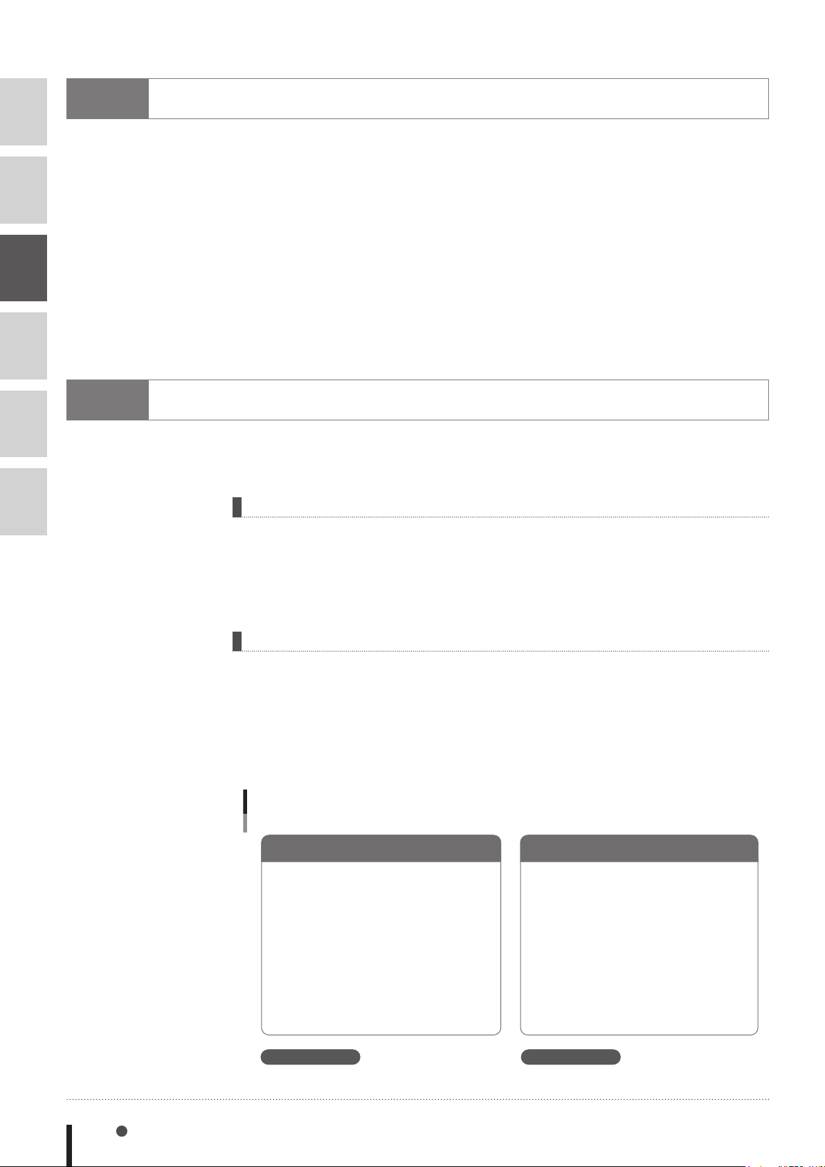
The X% value remains as "5". The X% value becomes "50".
2
3
4
5
7
Type Conversions
When different-type values are assigned to variables, the data type is converted as described below.
• When a real number is assigned to an integer type:
The decimal value is rounded off to the nearest whole number.
• When an integer is assigned to a real type:
The integer is assigned as it is, and is handled as a real number.
• When a numeric value is assigned to a character string type:
The numeric value is automatically converted to a character string.
• When a character string is assigned to numeric type:
This assignment is not possible,and an error will occur at the program is execution. Use the "VAL"
command to convert the character string to a numeric value, and that value is then assigned.
8
Value Pass-Along & Reference Pass-Along
A variable can be passed along when a sub-procedure is called by a CALL statement. This pass-
along can occur in either of two ways: as a value pass-along, or as a reference pass-along.
6
Value pass-along
With this method, the variable's value is passed along to the sub-procedure. Even if this value is
changed within the sub-procedure, the content of the call source variable is not changed.
A value pass-along occurs when the CALL statement's actual argument specifies a constant, an
expression, a variable, or an array element (array name followed by (subscript)).
Reference pass-along
With this method, the variable's reference (address in memory) is passed along to the sub-
procedure. If this value is changed within the sub-procedure, the content of the call source variable
is also changed.
A reference pass-along occurs when the CALL statement's actual argument specifies an entire array
(an array named followed by parenthetical content), or when the actual argument is preceded by
"REF".
Value pass-along & reference pass-along
Value pass-along Reference pass-along
X%=5
CALL *TEST( X% )
PRINT X%
HALT
SUB ROUTINE
’
SUB *TEST( A% )
A%=A%*10
END SUB
X%=5
CALL *TEST( REF X% )
PRINT X%
HALT
SUB ROUTINE
’
SUB *TEST( A% )
A%=A%*10
END SUB
Execution result: Execution result:
3-6 Chapter 3 Variables
33302-R7-00
Page 39
9
System Variables
1
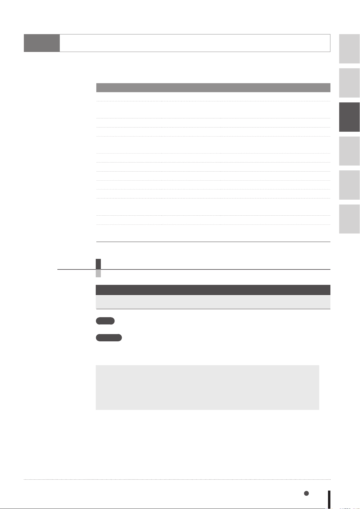
The following system variables are pre-defined, and other variable names must not begin with the
characters used for these system variable names.
Variable Type Format Meaning
Point variable
Shift variable Sn / S [expression] Species the shift number as a constant
Parallel input variable DI(mb), DIm(b) Parallel input signal status
Parallel output variable
Internal output variable
Arm lock output variable
Timer output variable TO(mb), TOm(b) For sequence program's timer function
Serial input variable SI(mb), SIm(b) Serial input signal status
Serial output variable SO(mb), SOm(b) Serial output signal setting and status
Serial word input SIW(m) Serial input's word information status
Serial double-word input
Serial word output SOW(m) Serial output's word information status
Serial double-word output
Pnnn / P [expression]
DO(mb), DOm(b) Parallel output signal setting and status
MO(mb), MOm(b) Controller's internal output signal setting
LO(mb), LOm(b) Axis-specic movement prohibit
SID(m) Serial input's double-word information
SOD(m) Serial output's double-word information
Species a point number
or as an expression
and status
status
status
2
3
4
5
6
9.1 Point variable
This variable specifies a point data number with a numeric constant or expression.
Format
Pnnnnn or P[expression]
Values n: Point number .................... 0 to 9
Functions A point data number is expressed with a "P" followed by a number of 5 digits or less, or
an expression surrounded by brackets ([expression])
Point numbers from 0 to 29999 can be specified with point variables.
Examples: P0
P110
P[A]
P[START_POINT]
P[A(10)]
System Variables 3-7
Page 40
1
2
3
4
9.2 Shift variable
This variable specifies a shift coordinate number with a numeric constant or expression.
Format
Snn or S[expression]
Values n: Shift number ..................... 0 to 9
Functions A shift number is expressed with an "S" followed by a 2-digits number or an expression
surrounded by brackets ([expression]). As a shift number, 0 to 39 can be specified.
Examples: S1
S[A]
S[BASE]
S[A(10)]
5
6
MEMO
• The "shift coordinate range" for each shift number can be changed from the programming box.
9.3 Parallel input variable
This variable is used to indicate the status of parallel input signals.
Format 1
DIm(b,···,b)
Format 2
DI(mb,···,mb)
Values m : port number .................... 0 to 7, 10 to 17, 20 to 27
b : bit definition .................... 0 to 7
If the bit definition is omitted in Format 1, bits 0 to 7 are all selected.
Examples: A%=DI1()
→Input status of ports DI(17) to DI(10)
is assigned to variable A%.
0 to 255 integer can be assigned to A%.
A%=DI5(7,4,0)
→Input status of DI(57), DI(54) and
DI(50) is assigned to variable A%.
A%=DI(27,15,10)
→Input status of DI(27), DI(15) and
DI(10) is assigned to variable A%.
WAIT DI(21)=1
→Waits for DI(21) to change to 1(ON).
(If all above signals are 1(ON), then A%=7.)
(If all above signals except DI(10) are 1 (ON), then A%=6.)
MEMO
3-8 Chapter 3 Variables
• When specifying multiple bits, specify them from left to right in descending order (high to low).
• A "0" is input if an input port does not actually exist.
Page 41

9.4 Parallel output variable
Specifies the parallel output signal or indicates the output status.
Format 1
1
DOm(b,···,b)
Format 2
DO(mb,···,mb)
Values m : port number .................... 0 to 7, 10 to 17, 20 to 27
b : bit definition .................... 0 to 7
If the bit definition is omitted in Format 1, bits 0 to 7 are all selected.
Examples: A%=DO2()
→Output status of DO(27) to DO(20) is
assigned to variable A%.
A%=DO5(7,4,0)
→Output status of DO(57), DO(54) and
DO(50) is assigned to variable A%.
A%=DO(37,25,20)
→Output status of DO(37), DO(25) and
DO(20) is assigned to variable A%.
(If all above signals except DO(20) are 1
(ON), then A%=6.)
DO3()=B%
→Changes to a status in which the DO(37)
For example, if B% is "123": If a binary
number is used, "123" will become
"01111011", DO(37) and DO(32) will become
"0", and the other bits will become "1".
DO4(5,4,0)=&B101
(If all above signals are 1(ON), then A%=7.)
to DO(30) output can be indicated by B%.
→DO(45) and DO(40) become "1", and DO(44) becomes "0".
2
3
4
5
6
MEMO
• When specifying multiple bits, specify them from left to right in descending order (high to low).
• If an output port does not actually exist, the data is not output externally.
System Variables 3-9
Page 42
1
2
3
4
5
6
9.5 Internal output variable
Specifies the controller's internal output signals and indicates the signal status.
Format 1
MOm(b,···,b)
Format 2
MO(mb,···,mb)
Values m : port number .................... 0 to 7, 10 to 17, 20 to 27, 30 to 33
b : bit definition .................... 0 to 7
• If the bit definition is omitted in Format 1, bits 0 to 7 are all selected.
Functions
These variables are used for signal communications, etc., with the sequence program.
Ports 30 to 33 are for dedicated internal output variables which can only be referenced
1. Port 30 indicates the status of origin sensors for axes 1 to 8 (in order from bit 0). Port
31 indicates the status of origin sensors for axes 9 to 16 (in order from bit 0).
Each bit sets to "1" when the origin sensor turns ON, and to "0" when OFF.
2. Port 34 indicates the HOLD status of axes 1 to 8 (in order from bit 0). Port 35 indicates
the HOLD status of axes 9 to 16 (in order from bit 0).
Each bit sets to "1" when the axis is in HOLD status, and to "0" when not.
I
nternal output variables which are used only in the controller, can set the status and refer.
(they cannot be changed).
MEMO
Bit 7 6 5 4 3 2 1 0
Port 30
Port 31
Port 34
Port 35
• Axes where no origin sensor is connected are always ON.
• Being in HOLD status means that the axis movement is stopped and positioned within the target
point tolerance while the servo is still turned ON.
• When the servo turns OFF, the HOLD status is released.
• Axes not being used are set to "1" (HOLD).
• The status of each axis in order from the smallest axis number used by robot 1 is maintained.
Example) In the case of a configuration where robot 1 has 5 axes and robot 2 has 4 axes, bits
0 to 4 of port 30 indicate the status of axes 1 to 5 of robot 1, bits 5 to 7 of port 30 indicate the
status of axes 1 to 3 of robot 2, and bit 0 of port 31 indicates the status of axis 4 of robot 2.
Axis 8
Axis 16
Origin sensor status 0: OFF / 1: ON (Axis 1 is not connected)
Axis 8
Axis 16
Hold status 0: RELEASE / 1: HOLD (Axis 1 is not connected)
Axis 7
Axis 15
Axis 7
Axis 15
Axis 6
Axis 14
Axis 6
Axis 14
Axis 5
Axis 13
Axis 5
Axis 13
Axis 4
Axis 12
Axis 4
Axis 12
Axis 3
Axis 11
Axis 3
Axis 11
Axis 2
Axis 10
Axis 2
Axis 10
Axis 1
Axis 9
Axis 1
Axis 9
3-10 Chapter 3 Variables
Page 43

Examples: A%=MO2 ()
→Internal output status of MO(27) to
MO(20) is assigned to variable A%.
A%=MO5(7,4,0)
→Internal output status of MO(57), MO(54)
and MO(50) is assigned to variable A%.
MEMO
A%=MO(37,25,20)
→Internal output status of MO(37), MO(25)
and MO(20) is assigned to variable A%.
(If all above signals except MO(25) are 1 (ON), then A%=5.)
•
When specifying multiple bits, specify them from left to right in descending order (
(If all above signals are 1 (ON), then A%=7.)
9.6 Arm lock output variable
Specifies axis-specific movement prohibit settings.
Format 1
LOm(b,···,b)
high to low
1
2
3
).
4
5
Format 2
LO(mb,···,mb)
Values m : port number .................... 0, 1
b : bit definition .................... 0 to 7
• If the bit definition is omitted in Format 1, bits 0 to 7 are all selected.
Functions The contents of this variable can be set the status and referred to as needed.
Of Port 0, bits 0 to 7 respectively correspond to axes 1 to 8, and of port 1, bits 0 to
respectively correspond to axes 9 to 16.
When this bit is ON, movement on the corresponding axis is prohibited.
Examples:
A%=LO0()
→Arm lock status of LO(07) to LO(00) is assigned to variable A%.
A%=LO0(7,4,0)
→Arm lock status of LO(07), LO(04) and LO(00) is assigned to variable A%.
(If all above signals are 1(ON), then A%=7.)
A%=LO0(06,04,01)
→Arm lock status of LO(06), LO(04) and LO(01) is assigned to variable A%.
(If all above signals except LO(01) are 1(ON), then A%=6.)
LO1
=&B0010
()
→LO(11) is set to 1(ON),then movement of axis 10 is prohibited.
LO1(2,0)=3
→LO(12) and LO(10) are set to 1(ON),
then movements of axes 11 and 9 are prohibited.
6
System Variables 3-11
Page 44
1
2
3
MEMO
• When specifying multiple bits, specify them from left to right in descending order (high to low).
• Servo OFF to ON switching is disabled if an arm lock is in effect at even 1 axis.
• When performing JOG movement in the MANUAL mode, axis movement is possible at axes
where an arm lock status is not in effect, even if an arm lock status is in effect at another axis.
• When executing movement commands from the program, etc., the "12.401 Arm locked" error
will occur if an arm lock status is in effect at the axis in question.
• Arm locks sequentially correspond to axes in order from the axis with the smallest axis number
used by robot 1.
Example) In the case of a configuration where robot 1 has 5 axes and robot 2 has 4 axes, the
status of axes 1 to 5 of robot 1 is set by bits 0 to 4 of port 0, the status of axes 1 to 3 of robot 2
is set by bits 5 to 7 of port 0, and the prohibition of motion of axis 4 of robot 2 is set by bit 0 of
port 1.
4
5
6
9.7 Timer output variable
This variable is used in the timer function of a sequence program.
Format 1
TOm(b,···,b)
Format 2
TO(mb,···,mb)
Values m : port number .................... 0, 1
b : bit definition .................... 0 to 7
• If the bit definition is omitted in Format 1, bits 0 to 7 are all selected.
Functions The contents of this variable can be changed and referred to as needed.
Timer function can be used only in the sequence program. If this variable is output in a
normal program, it is an internal output.
For details regarding sequence program usage examples, refer to the timer usage examples given in
"4.2 Input/output variables" in Chapter 7.
MEMO
3-12 Chapter 3 Variables
• When specifying multiple bits, specify them from left to right in descending order (high to low).
Examples: A%=TO0()
→Status of TO(07) to TO(00) is assigned
to variable A%.
A%=TO0(7,4,0)
→Status of TO(07), TO(04) and TO(00) is
assigned to variable A%.
A%=TO(06,04,01)
→Status of TO(06), TO(04) and TO(01) is
assigned to variable A%.
(If all above signals except TO(01) are 1
(ON), then A%=6.)
(If all above signals are 1 (ON), then A%=7.)
Page 45

9.8 Serial input variable
This variable is used to indicate the status of serial input signals.
Format 1
SIm(b,···,b)
Format 2
SI(mb,···,mb)
Values m : port number .................... 0 to 7, 10 to 17, 20 to 27
b : bit definition .................... 0 to 7
• If the bit definition is omitted in Format 1, bits 0 to 7 are all selected.
Examples: A%=SI1()
→Input status of ports SI(17) to SI(10)
is assigned to variable A%.
A%=SI5(7,4,0)
→Input status of SI(57), SI(54) and
SI(50) is assigned to variable A%.
A%=SI(27,15,10)
→Input status of SI(27), SI(15) and
SI(10) is assigned to variable A%.
(If all above signals except SI(10) are 1^
(ON), then A%=6.)
WAIT SI(21)=1
→Waits until SI(21) sets to 1 (ON).
(If all above signals are 1(ON), then A%=7.)
1
2
3
4
5
6
MEMO
• When specifying multiple bits, specify them from left to right in descending order (high to law).
• A "0" is input if a serial port does not actually exist.
System Variables 3-13
Page 46

1
2
3
4
5
6
9.9 Serial output variable
This variable is used to define the serial output signals and indicate the output status.
Format 1
SOm(b,···,b)
Format 2
SO(mb,···,mb)
Values m : port number .................... 0 to 7, 10 to 17, 20 to 27
b : bit definition .................... 0 to 7
• If the bit definition is omitted in Format 1, bits 0 to 7 are all selected.
Examples: A%=SO2()
→Output status of SO(27) to SO(20) is
assigned to variable A%.
A%=SO5(7,4,0)
→Output status of SO(57), SO(54) and
SO(50) is assigned to variable A%.
(If all above signals turn 1(ON), then A%=7.)
MEMO
A%=SO(37,25,20)
→Output status of SO(37), SO(25) and
SO(20) is assigned to variable A%.
SO3()=B%
→Changes the output status of SO(37) to
SO(30) to one indicated by B%.
(If B% is 123, 123 is expressed B01111011 as a binary number,
that means SO(37) and SO(32) turn 0(OFF), the other bits turn 1(ON).)
SO4(5,4,0)=&B101
→DO(45) and DO(40) turn 1(ON), DO(44) turns 0(OFF).
• When specifying multiple bits, specify them from left to right in descending order (high to law).
• If a serial port does not actually exist, the data is not output externally.
(If all above signals except SO(25) turn 1(ON), then A%=5.)
3-14 Chapter 3 Variables
Page 47
9.10 Serial word input
This variable indicates the status of the serial input word information.
Format
SIW(m)
Values m : port number .................... 2 to 15
The acquisition range is 0 (&H0000) to 65,535 (&HFFFF).
1
2
Examples: A%=SIW(2)
→The input status from SIW (2) is
assigned to variable A%.
A%=SIW(15)
→The input status from SIW (15) is
assigned to variable A%.
MEMO
• The information is handled as unsigned word data.
• "0" is input if a serial port does not actually exist.
9.11 Serial double word input
This variable indicates the state of the serial input word information as a double word.
Format
SID(m)
Values m : port number .................... 2, 4, 6, 8, 10, 12, 14
The acquisition range is -2,147,483,648(&H80000000) to 2,147,483,647(&H7FFFFFFF).
3
4
5
6
MEMO
Examples: A%=SID(2)
→The input status from SIW (2) , SIW (3)
is assigned to variable A%.
A%=SID(14)
→The input status from SIW (14), SIW (15)
is assigned to variable A%.
• The information is handled as signed double word data.
• "0" is input if a serial port does not actually exist.
• The lower port number data is placed at the lower address.
For example, if SIW(2) =&H2345, SIW(3) =&H0001, then SID(2) =&H00012345.
System Variables 3-15
Page 48
1
2
3
4
5
6
9.12 Serial word output
Outputs to the serial output word information or indicates the output status.
Format
SOW(m)
Values m : port number .................... 2 to 15
The output range is 0 (&H0000) to 65,535 (&HFFFF).
Note that if a negative value is output, the low-order word information will be output
after being converted to hexadecimal.
Examples: A%=SOW(2)
→The output status of SOW (2) is
assigned to variable A%.
SOW(15)=A%
→The contents of variable A% are
assigned in SOW (15).
the low-order word information will be assigned.
SOW(15)=-255
→The contents of -255 (&HFFFFFF01) are
assigned to SOW (15).
word information (&HFF01) will be assigned.
If the variable A% value exceeds the output range,
-255 is a negative value, so the low-order
MEMO
• The information is handled as unsigned word data.
• If a serial port does not actually exist, the data is not output externally.
• If a value exceeding the output range is assigned, the low-order 2-byte information is output.
9.13 Serial double word output
Output the status of serial output word information in a double word, or indicates the output status.
Format
SOD(m)
Values m : port number .................... 2, 4, 6, 8, 10, 12, 14
The output range is -2,147,483,648(&H80000000) to 2,147,483,647(&H7FFFFFFF).
Examples: A%=SOD(2)
→The output status of SOD (2) is assigned to variable A%.
SOD(14)=A%
→The contents of variable A% are assigned in SOD (14).
MEMO
3-16 Chapter 3 Variables
• The information is handled as signed double word data.
• If a serial port does not actually exist, the data is not output externally.
• The lower port number data is placed at the lower address.
For example, if SOW(2) =&H2345, SOW(3) =&H0001, then SOD(2) =&H00012345.
Page 49
10
Bit Settings
1
Bits can be specified for input/output variables by any of the following methods.
1. Single bit
To specify only 1 of the bits, the target port number and bit number are specified in parentheses.
The port number may also be specified outside the parentheses.
Programming example: DOm(b)DOm(b)
Example: DO(25) Specifies bit 5 of port 2.
DO2(5)
2. Same-port multiple bits
To specify multiple bits at the same port, those bit numbers are specified in parentheses (separated
by commas) following the port number.
The port number may also be specified in parentheses.
Programming example: DOm(b,b,…,b) DO(mb,mb,…,mb)
Example: DO2(7,5,3) Specifies DO(27), DO(25), DO(23)
DO(27,25,23)
3. Different-port multiple bits
To specify multiple bits at different ports, 2-digit consisting of the port number and the bit number
must be specified in parentheses and must be separated by commas. Up to 8 bits can be written.
2
3
4
5
6
Programming example: DO(mb,mb,…,mb)
Example: DO(37,25,20)
Specifies DO(37), DO(25), DO(20).
4. All bits of 1 port
To specify all bits of a single port, use parentheses after the port number. Methods 2 and 3 shown
above can also be used.
Programming example: DOm()
Example: DO2() Specifies all the DO(27) to DO(20) bits
→The same result can be obtained by the following:
DO(27,26,25,24,23,22,21,20)
or,
DO2(7,6,5,4,3,2,1,0)
Bit Settings 3-17
Page 50
1
2
3
4
5
6
11
Valid range of variables
11.1 Valid range of dynamic (array) variables
Dynamic (array) variables are divided into global variables and local variables, according to their
declaration position in the program. Global and local variables have different valid ranges.
Variable Type Explanation
MEMO
Global variables
Local variables
• For details regarding arrays, refer to Chapter 3 "5 Array variables".
• A variable declared at the program level can be referenced from a sub-procedure without
being passed along as a dummy argument, by using the SHARED statement (for details, refer to
Chapter 8 "111 SHARED").
Variables are declared outside of sub-procedures (outside of
program areas enclosed by a SUB statement and END SUB
statement). These variables are valid throughout the entire program.
Variables are declared within sub-procedures and are valid only in
these sub-procedures.
11.2 Valid range of static variables
Static variable data is not cleared when a program reset occurs. Moreover, variable data can be
changed and referenced from any program.
The variable names are determined as shown below (they cannot be named as desired).
Variable type Variable name
Integer variable SGIn (n: 0 to 31)
Real variable SGRn (n: 0 to 31)
3-18 Chapter 3 Variables
Page 51
12
Clearing variables
12.1 Clearing dynamic variables
In the cases below, numeric variables are cleared to zero, and character variables are cleared to a
null string. The array is cleared in the same manner.
■
When a program reset occurs.
■
When dedicated input signal DI15 (program reset input) was turned on while the program was
stopped in AUTO mode.
■
When either of the following is initialized by an initialization operation.
1. Program memory
2. Entire memory
■
When any of the following online commands was executed.
@RESET, @INIT PGM, @INIT MEM, @INIT ALL
■
When the HALTALL statement was executed in the program (HALT statement does not clear
dynamic variables).
12.2 Clearing static variables
In the cases below, integer variables and real variables are cleared to zero.
■
When the following is initialized by an initialization operation.
Entire memory
■
When any of the following online commands was executed.
@INIT MEM, @INIT ALL
1
2
3
4
5
6
Clearing variables 3-19
Page 52

Page 53

Chapter 4
Expressions and Operations
1 1
Arithmetic operations ..............................
2 2
Character string operations ....................
3 3
Point data format ......................................
4 4
DI/DO conditional expressions ...............
4-1
4-4
4-5
4-6
Page 54

Page 55
1
Arithmetic operations
1
1.1 Arithmetic operators
Operators
+ A+B Adds A to B
- A-B Subtracts B from A
* A*B Multiplies A by B
/ A/B Divides A by B
^ A^B Obtains the B exponent of A (exponent operation)
- -A Reverses the sign of A
MOD A MOD B Obtains the remainder A divided by B
When a "remainder" (MOD) operation involves real numbers, the decimal value is rounded off to
the nearest whole number which is then converted to an integer before the calculation is executed.
The result represents the remainder of an integer division operation.
Examples: A=15 MOD 2 → A=1(15/2=7....1)
A=17.34 MOD 5.98 → A=2(17/5=3....2)
Usage Example
1.2 Relational operators
Relational operators are used to compare 2 values. If the result is "true", a "-1" is obtained. If it is
"false", a "0" is obtained.
Operators
= A=B "-1" if A and B are equal, "0" if not.
<>, >< A<>B "-1" if A and B are unequal, "0" if not.
< A<B "-1" if A is smaller than B, "0" if not.
> A>B "-1" if A is larger than B, "0" if not.
<=, =< A<=B "-1" if A is equal to or smaller than B, "0" if not.
>=, => A>=B "-1" if A is equal to or larger than B, "0" if not.
Usage Example
Meaning
2
3
4
5
6
Meaning
MEMO
Examples: A=10>5
• When using equivalence relational operators with real variables and real arrays, the desired
result may not be obtained due to the round-off error.
Examples: ............................. A=2
Since 10 > 5 is "true", A = -1.
→
B=SQR(A!)
IF A!=B!*B! THEN...
In this case, A! will be unequal to B!*B!.
→
Arithmetic operations 4-1
Page 56
1.3 Logic operations
1
2
3
4
5
6
Logic operators are used to manipulate 1 or 2 values bit by bit. For example, the status of an I/O
port can be manipulated.
■
Depending on the logic operation performed, the results generated are either 0 or 1.
■
Logic operations with real numbers convert the values into integers before they are executed.
Operators Functions Meaning
NOT, ~ Logical NOT Reverses the bits.
AND, & Logical AND Becomes "1" when both bits are "1".
OR, | Logical OR Becomes "1" when either of the bits is "1".
XOR Exclusive OR Becomes "1" when both bits are different.
EQV
IMP
Examples: A%=NOT 13.05 → "-14" is assigned to A% (reversed after being rounded off to 13).
Bit 7 6 5 4 3 2 1 0
13 0 0 0 0 1 1 0 1
NOT 13=-14 1 1 1 1 0 0 1 0
Logical equivalence
operator
Logical implication
operator
Becomes "1" when both bits are equal.
Becomes "0" when the rst bit is "1" and the second bit
is "0".
Examples: A%=3 AND 10 → "2" is assigned to A%
Bit 7 6 5 4 3 2 1 0
3 0 0 0 0 0 0
10 0 0 0 0 1 0
3 AND 10 = 2 0 0 0 0 0 0
Examples: A%=3 OR 10
Bit 7 6 5 4 3 2 1 0
3 0 0 0 0
10 0 0 0 0
3 OR 10 = 11 0 0 0 0
Examples: A%=3 XOR 10
Bit 7 6 5 4 3 2 1 0
3 0 0 0 0
10 0 0 0 0
3 XOR 10 = 9 0 0 0 0
"11" is assigned to A%
→
"9" is assigned to A%
→
1
1
1
0
1
1
0
1
1
0
0
0
0 1
0 1
0 0
1 1
1 0
1 1
1
0
0
1
0
1
4-2 Chapter 4 Expressions and Operations
Page 57

1.4 Priority of arithmetic operation
Operations are performed in the following order of priority. When two operations of equal priority
appear in the same statement, the operations are executed in order from left to right.
Priority Rank Arithmetic Operation
1 Expressions included in parentheses
2 Functions, variables
3 ^ (exponents)
4 Independent "+" and "-" signs (Monominal operators)
5 * (Multiplication), / (Division)
6 MOD
7 + (Addition), - (Subtraction)
8 Relational operators
9 NOT, ~ (Logical NOT)
10 AND, & (Logical AND)
11 OR, |, XOR (Logical OR, exclusive OR)
12 EQV (Logical equivalence)
13 IMP (Logical implication)
1.5 Data format conversion
1
2
3
4
5
6
Data format is converted in cases where two values of different formats are involved in the same
operation.
1. When a real number is assigned to an integer, decimal places are rounded off.
Examples: A%=125.67
2. When integers and real numbers are involved in the same operation, the result
becomes a real number.
Examples: A(0)=125 * 0.25 → A(0)=31.25
3. When an integer is divided by an integer, the result is an integer with the remainder
discarded.
Examples: A(0)=100/3
A%=126
→
A(0)=33
→
Arithmetic operations 4-3
Page 58
1
2
3
4
5
6
2
Character string operations
2.1 Character string connection
Character strings may be combined by using the "+" sign.
SAMPLE
A$="OMRON"
B$="ROBOT"
C$="LANGUAGE"
D$="MOUNTER"
E$=A$+" "+B$+" "+C$
F$=A$+" "+D$
PRINT E$
PRINT F$
Results: OMRON ROBOT LANGUAGE
OMRON MOUNTER
2.2 Character string comparison
Characters can be compared with the same relational operators as used for numeric values.
Character string comparison can be used to find out the contents of character strings, or to sort
character strings into alphabetical order.
■
In the case of character strings, the comparison is performed from the beginning of each string,
character by character.
■
If all characters match in both strings, they are considered to be equal.
■
Even if only one character in the string differs from its corresponding character in the other string,
then the string with the larger (higher) character code is treated as the larger string.
■
When the character string lengths differ, the longer of the character strings is judged to be the
greater value string.
All examples below are "true".
Examples: "AA"<"AB"
"X&">"X#"
"DESK"<"DESKS"
4-4 Chapter 4 Expressions and Operations
Page 59
3
•The data format is
•Plus (+) signs can be
Point data format
NOTE
common for axes 1
to 6 for both the joint
coordinate format and
the Cartesian coordinate
format.
omitted.
There are two types of point data formats: joint coordinate format and Cartesian coordinate format.
Point numbers are in the range of 0 to 29999.
Coordinate Format
Joint coordinate
format
Cartesian
coordinate
format
When setting an extended hand system flag for SCARA robots, set either "1" or "2" at the end of the
data. If a value other than "1" or "2" is set, or if no value is designated, "0" will be set to indicate that
no hand system flag is set.
Hand System Data Value
RIGHTY (right-handed system) 1
LEFTY (left-handed system) 2
Data Format Explanation
± nnnnnnn This is a decimal integer constant of 8 digits
or less with a plus or minus sign, and can be
specied from –99999999 to 99999999.
Unit: [pulses]
± nnn.nn to ± nnnnnnn This is a decimal fraction of a total of 7 digits
including 3 or less decimal places.
Unit: [mm] or [degrees]
1
2
3
4
5
6
Point data format 4-5
Page 60
1
2
3
4
5
4
DI/DO conditional expressions
DI/DO conditional expressions may be used to set conditions for WAIT statements and STOPON
options in MOVE statements.
Numeric constants, variables and arithmetic operators that may be used with DI/DO conditional
expressions are shown below.
• Constant
Decimal integer constant, binary integer constant, hexadecimal integer constant
• Variables
Global integer type, global real type, input/output type
• Operators
Relational operators, logic operators
• Operation priority
1. Relational operators
2. NOT, ~
3. AND, &
4. OR, |, XOR
6
Examples:
DI34 turns ON.
WAIT DI(31)=1 OR DI(34)=1
The program waits until either DI31 or
→
4-6 Chapter 4 Expressions and Operations
Page 61

Chapter 5
Multiple Robot Control
1 1
Overview ...................................................
2 2
Command list with a robot setting ..........
5-1
5-2
Page 62

Page 63
1
Overview
1
YRCX can be used to control multiple robots (up to 4).
The multi-task function also enables multiple robots to move asynchronously.
To use this function, settings for multiple robots or settings for auxiliary axes must be made in the
system prior to shipment.
The following settings are possible to the axes of robots.
■
Robot 1 (4 axes)
■
Robot 1 (4 axes) + robot 2 (4 axes) (when using the YC-LINK/E option)
■
Robot 1 (4 axes) + robot 2 (4 axes) + robot 3 (4 axes) + robot 4 (4 axes)
(when using the YC-LINK/E option)
2
3
Each robot consists of normal axes and auxiliary axes.
When using one robot without auxiliary axes, the setting is made only to normal axes.
Axes configuration
1. For robot 1
Main group
2. For 1 robot with no auxiliary axes used
Robot 1
Robot 1 normal axis
(Number of axes: 4)
Robot 1 robot
(Number of axes: 4)
Robot 1 auxiliary axis
(Number of axes: 4)
Robot 1 auxiliary axis
(None)
4
5
6
33501-R9-00
Overview 5-1
Page 64
1
2
3
4
5
6
2
Command list with a robot setting
The special commands and functions for robot movements and coordinate control are common
for all robots. A robot can be specified with an option of a command. Main commands are shown
below.
Operator Command name
Robot movement DRIVE
MOVE
MOVET
PMOVE
WAIT ARM
Coordinate control CHANGE
LEFTY
RIGHTY
Status change ACCEL
ARCHP2
ARMTYP
AXWGHT
MSPEED
OUTPOS
TOLE
Point operation JTOXY
XYTOJ
Parameter reference ACCEL
ARCHP2
AXWGHT
ORGORD
TOLE
Status reference ABSRPOS
ARMSEL
CURTQST
MCHREF
WHRXY
Torque control TORQUE
TRQTIME
DRIVEI
MOVEI
PATH
SERVO
HAND
PATH
SHIFT
ARCHP1
ARMSEL
ASPEED
DECEL
ORGORD
SPEED
WEIGHT
WHERE
WHRXY
ARCHP1
ARMTYP
DECEL
OUTPOS
WEIGHT
ARMCND
ARMTYP
CURTRQ
WHERE
TRQSTS
CURTRQ
■
An axis specified as an auxiliary axis cannot be moved with the MOVE, MOVEI, MOVET and
PMOVE commands. Use the DRIVE or DRIVEI command to move it.
5-2 Chapter 5 Multiple Robot Control
Page 65

Chapter 6
Multi-tasking
1 1
Outline .......................................................
2 2
Task definition method .............................
3 3
Task status and transition .........................
4 4
Multi-task program example ..................
5 5
Sharing the data .......................................
6 6
Cautionary Items ......................................
6-1
6-1
6-2
6-8
6-8
6-9
Page 66

Page 67

1
Outline
1
The multi-task function performs multiple processing simultaneously in a parallel manner, and can
be used to create programs of higher complexity. Before using the multi-task function, read this
section thoroughly and make sure that you fully understand its contents.
Multi-tasking allows executing two or more tasks in parallel. However, this does not mean that
multiple tasks are executed simultaneously because the controller has only one CPU to execute the
tasks. In multi-tasking, the CPU time is shared among multiple tasks by assigning a priority to each
task so that they can be executed efficiently.
2
3
■
A maximum of 16 tasks (task 1 to task 16) can be executed in one program.
■
Tasks can be prioritized and executed in their priority order (higher priority tasks are executed first).
■
The priority level can be set to any level between 1 and 64.
■
Smaller values have higher priority, and larger values have lower priority
(High priority: 1 ⇔ 64: low priority).
2
Task definition method
A task is a set of instructions which are executed as a single sequence. As explained below, a task is
defined by assigning a label to it.
4
5
1. Create one program that describes a command which is to be defined as a task.
2. In the START statement of the program that will be a main task, specify the program created at
Step 1 above. Task numbers are then assigned, and the program starts.
SAMPLE
’MAIN TASK(TASK1)
START <SUB_PGM>,T2 ·················
*ST1:
MOVE P,P1,P0
IF DO(20)= 1 THEN
HALTALL
ENDIF
GOTO *ST
HALTALL
Program name:SUB_PGM
’SUB TASK(TASK2)
*IOTASK: ························ Task 2 begins here
IF DI(21)=1 THEN
DO(30)=1
ELSE
DO(30)=0
ENDIF
GOTO *IOTASK ······················· Task 2 processing ends here
EXIT TASK
<SUB_PGM> is started as Task 2
6
Outline 6-1
Page 68
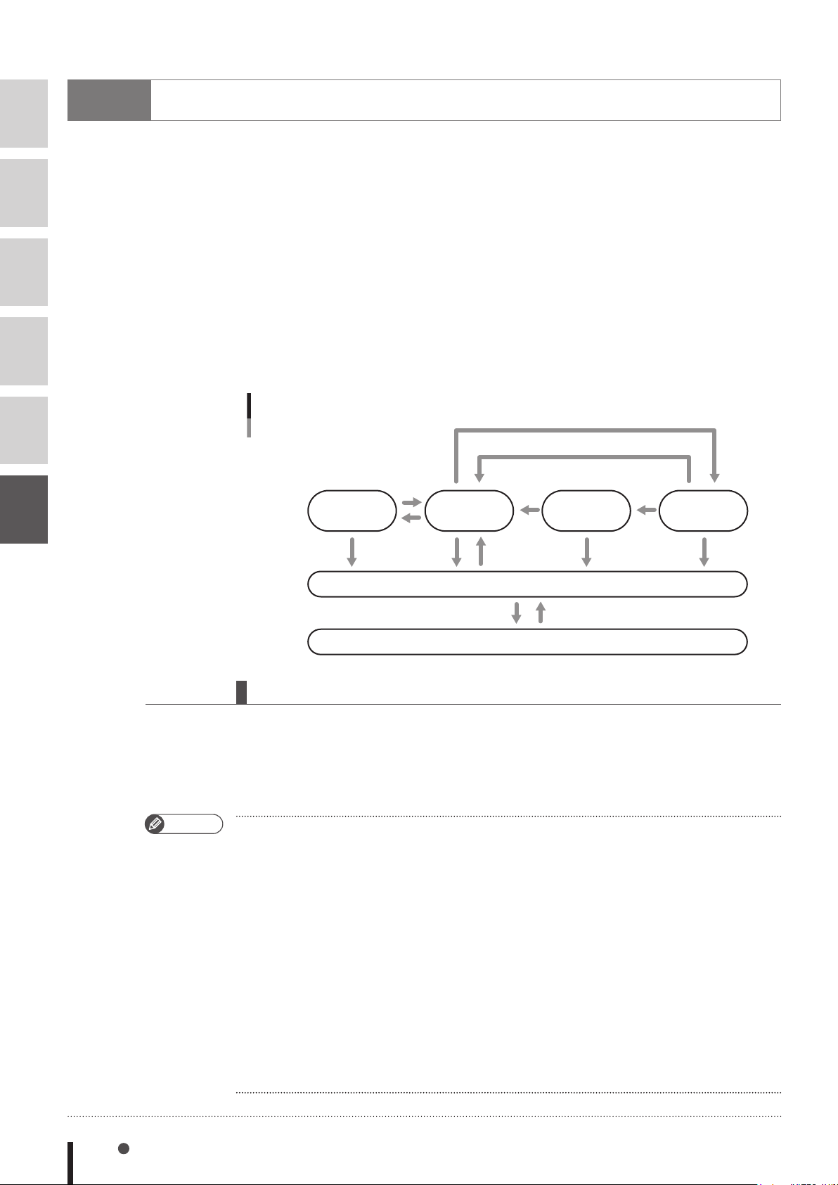
1
2
3
4
5
3
Task status and transition
There are 6 types of task status.
1. STOP status
A task is present but the task processing is stopped.
2. RUN status
A task is present and the task processing is being executed by the CPU.
3. READY status
A task is present and ready to be allocated to the CPU for task processing.
4. WAIT status
A task is present and waiting for an event to begin the task processing.
5. SUSPEND status
A task is present but suspended while waiting to begin the task processing.
6. NON EXISTENT status
No tasks exist in the program. (The START command is used to perform a call.)
Task state transition
CPU assignment
Wait for CPU assignment
6
3.1 Starting tasks
When the START command is executed, a specified program is registered in the task and placed in
RUN status. If the task number (1 to 16) is not specified by the START command, the task with the
smallest number among the tasks yet to be started is automatically specified. For details regarding
the START command, refer to "123 START" in Chapter 8.
MEMO
• When the LOAD command is executed, a specified program is registered in the task and placed
in a STOP status. For details of the LOAD command, refer to "1. Register task" of "2.1 Program
operations" in Chapter 12.
• If another program is already registered in the task number specified by the START command or
the LOAD command, the "6.215: Task running" error will occur.
•
When programs are registered in all task numbers and the START command or the LOAD command
is executed without specifying the task number, the "6.263: Too many Tasks" error will occur.
• When the HALTALL command is executed, all tasks termitate and the task enters the NON
EXISTENT (no task registration) status. When the main program is specified, the HALTALL
command registers the main program in the task 1 and stops at the beginning line. When the
main program is not specified, the HALTALL command registers the program that has been
executed last (current program) in the task 1 and stops at the beginning line.
For details regarding the main program, refer to "Setting the main program" of YRCX operator's
manual.
Restart
Suspend
Cancel waiting
Start
STOP
Delete Call
NON EXISTENT
Wait condition
RUNSUSPEND READY WAIT
StopStop Stop Stop
33601-R9-00
6-2 Chapter 6 Multi-tasking
Page 69
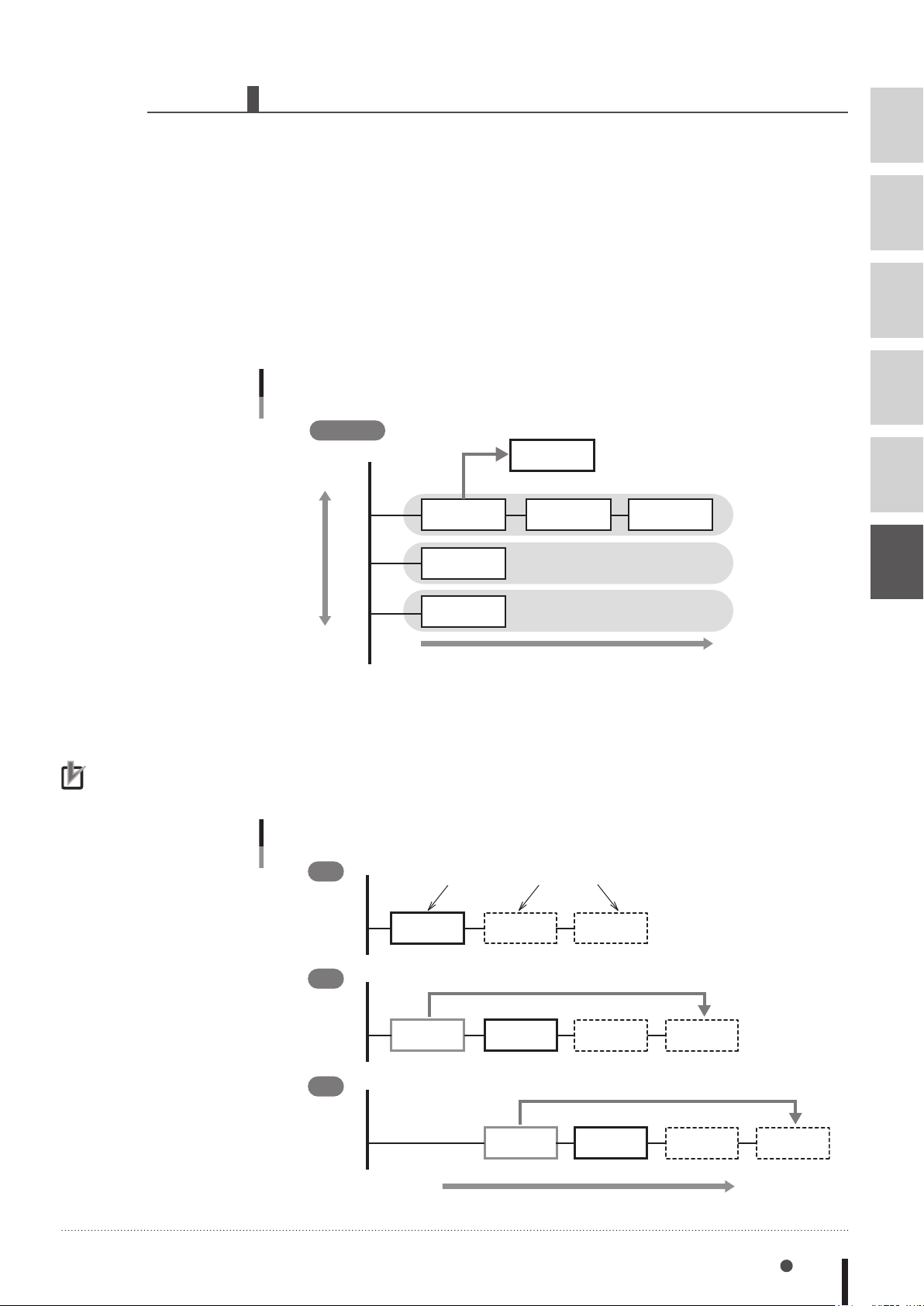
3.2 Task scheduling
Order in which tasks are put in READY status.
The head of the task with the highest priority
Execution sequence
Task scheduling determines the priority to be used in allocating tasks in the READY (execution
enabled) status to the CPU and executing them.
When there are two or more tasks which are put in the READY status, ready queues for CPU
allocation are used to determine the priority for executing the tasks. One of these READY status
tasks is then selected and executed (RUN status).
Only tasks with the same priority ranking are assigned to a given ready queue. Therefore, where
several tasks with differing priority rankings exist, a corresponding number of ready queues are
created. Tasks within a given ready queue are handled on a first come first serve (FCFS) basis. The
task where a READY status is first established has priority. The smaller the number, the higher the
task priority level.
Task scheduling
Priority level
High
Task 1
32
Task 1 Task 3
33
Task 5
is put in RUN status.
Task 4
Ready queue 1
Ready queue 2
1
2
3
4
5
6
NOTE
•When the prescribed CPU
occupation time elapses,
the active command is
ended, and processing
moves to the next task.
However, if there are no
other tasks of the same
or higher priority (same
or higher ready queue),
the same task will be
executed again.
34
Task 2
Low
Ready queue 3
33602-R7-00
A RUN status task will be moved to the end of the ready queue if placed in a READY status by any
of the following causes:
1) A WAIT status command was executed.
2) The CPU occupation time exceeds a specified time.
3) A task with a higher priority level is put in READY status.
Ready queue
1
2
RUN status READY status
Task 1
Moves to the end of the ready queue, and Task 3 is executed.
Task 1 Task 3 Task 4 Task 1
Task 3 Task 4
3
Moves to the end of the ready queue, and Task 4 is executed.
Task 3 Task 4 Task 1 Task 3
33603-R7-00
Task status and transition 6-3
Page 70
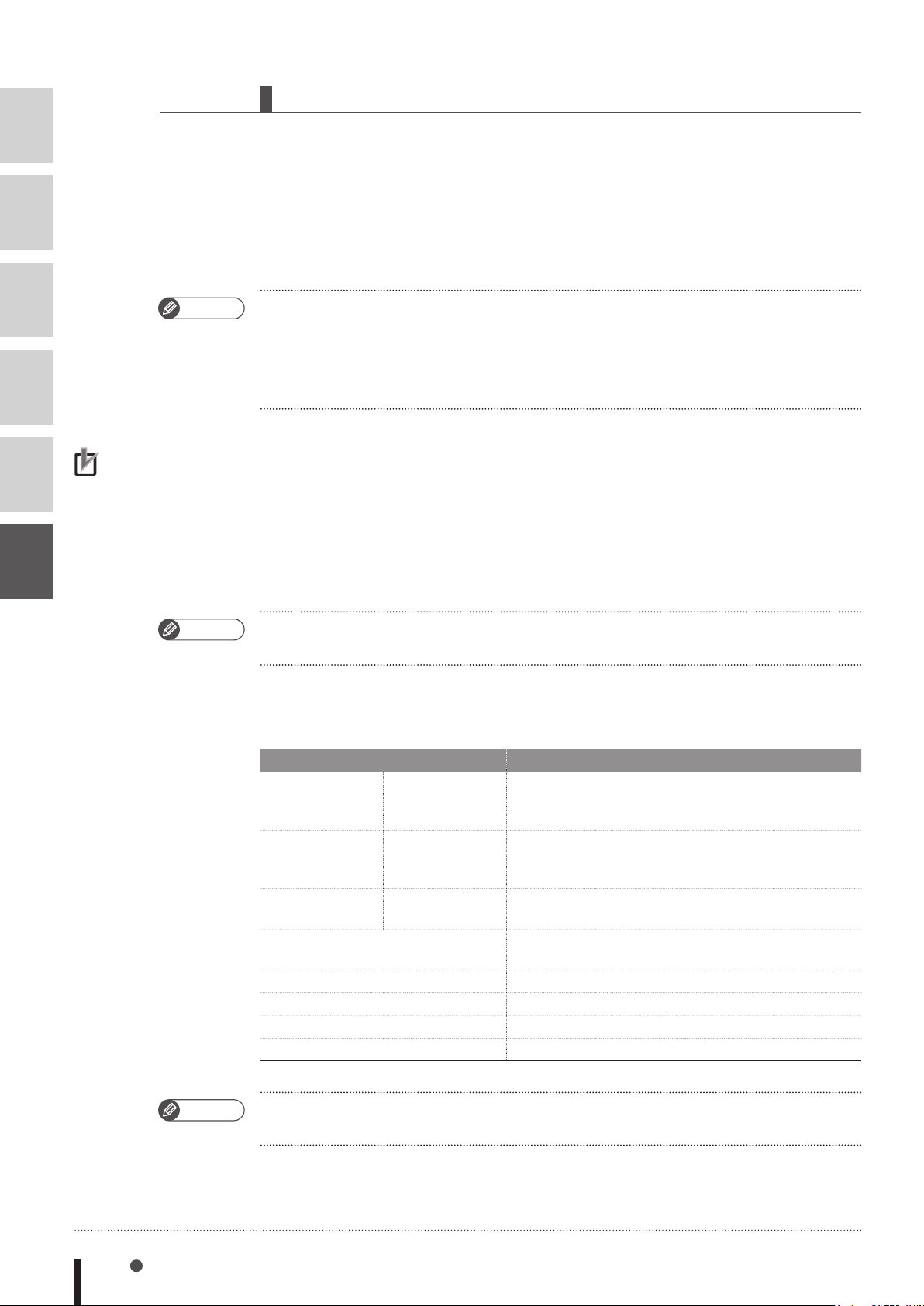
3.3 Condition wait in task
1
2
3
4
5
6
MEMO
NOTE
•If multiple tasks are in
WAIT status awaiting the
same condition event, or
different condition events
occur simultaneously, all
tasks for which the waited
events occur are put in
READY status.
A task is put in the WAIT status (waiting for an event) when a command causing WAIT status is
executed for that task. At this time, the transition to READY status does not take place until the wait
condition is canceled.
1. When a command causing WAIT status is executed, the following transition happens.
■
Task for which a command causing WAIT status is executed → WAIT status
■
Task at the head of the ready queue with higher priority → RUN status
•
For example, when a MOVE statement (a command that establishes WAIT status)
is executed, the CPU sends a "MOVE" instruction to the driver, and then waits for
a "MOVE COMPLETED" reply from the driver. This is "waiting for an event" status.
In this case, WAIT status is established at the task which executed the MOVE command, and that
task is moved to the end of the ready queue. RUN status is then established at the next task.
2. When an event waited by the task in the WAIT status occurs, the following status
transition takes place by task scheduling.
■
Task in the WAIT status for which the awaited event occurred → READY status
However, if the task put in the READY status was at the head of the ready queue with the
highest priority, the following transition takes place.
1) Task that is currently in RUN status → READY status
2) Task at the head of the ready queue with higher priority → RUN status
MEMO
• In the above MOVE statement example, the task is moved to the end of the ready queue. Then,
when a "MOVE COMPLETED" reply is received, this task is placed in READY status.
Tasks are put in WAIT status by the following commands.
Event Command
Wait for axis
movement to
complete
Wait for time to elapse DELAY, SET (Time should be specified.), WAIT ARM
Wait for condition to be met WAIT
Wait for data to send or to be received SEND
Wait for print buffer to become empty PRINT
Wait for key input INPUT
Axis movement
command
Parameter
command
Robot status
change command
MOVE
DRIVEI
SERVO
ACCEL
DECEL
WEIGHT
CHANGE
MSPEED
(Time should be specied.)
MOVEI
PMOVE
WAIT ARM
ARCHP1
OUTPOS
SHIFT
SPEED
MOVET
PATH
ARCHP2
TOLE
LEFTY ASPEED
DRIVE
MOTOR
AXWGHT
ORGORD
MEMO
6-4 Chapter 6 Multi-tasking
• The tasks are not put in WAIT status if the event has been established before the above
commands are executed.
Page 71
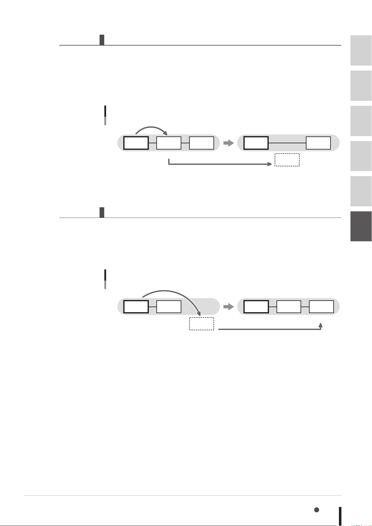
3.4 Suspending tasks (SUSPEND)
and is removed from the ready queue.
and is assigned to a ready queue.
The SUSPEND command temporarily stops tasks other than task 1 and places them in SUSPEND
status.
When the SUSPEND command is executed, the status transition takes place as follows.
■
Task that executed the SUSPEND command → RUN status
■
Specified task
Suspending tasks (SUSPEND)
SUSPEND
Task 1
RUN READY RUN
Task 2
The task is placed in a SUSPEND status,
Task 3
READY
3.5 Restarting tasks (RESTART)
Tasks in the SUSPEND status can be restarted with the RESTART command.
When the RESTART command is executed, the status transition takes place as follows.
SUSPEND status
→
Task 1
Task 2
SUSPEND
Task 3
READY
33604-R7-00
1
2
3
4
5
6
■
Task for which the RESTART command was executed
■
Specified task
Restarting tasks (RESTART)
RESTART
Task 1
RUN
Task 3
READY
Task 2
SUSPEND
RUN status
→
READY status
→
Task 1 Task 3
RUN READY
The task is placed in a READY status,
Task 2
READY
33605-R7-00
Task status and transition 6-5
Page 72
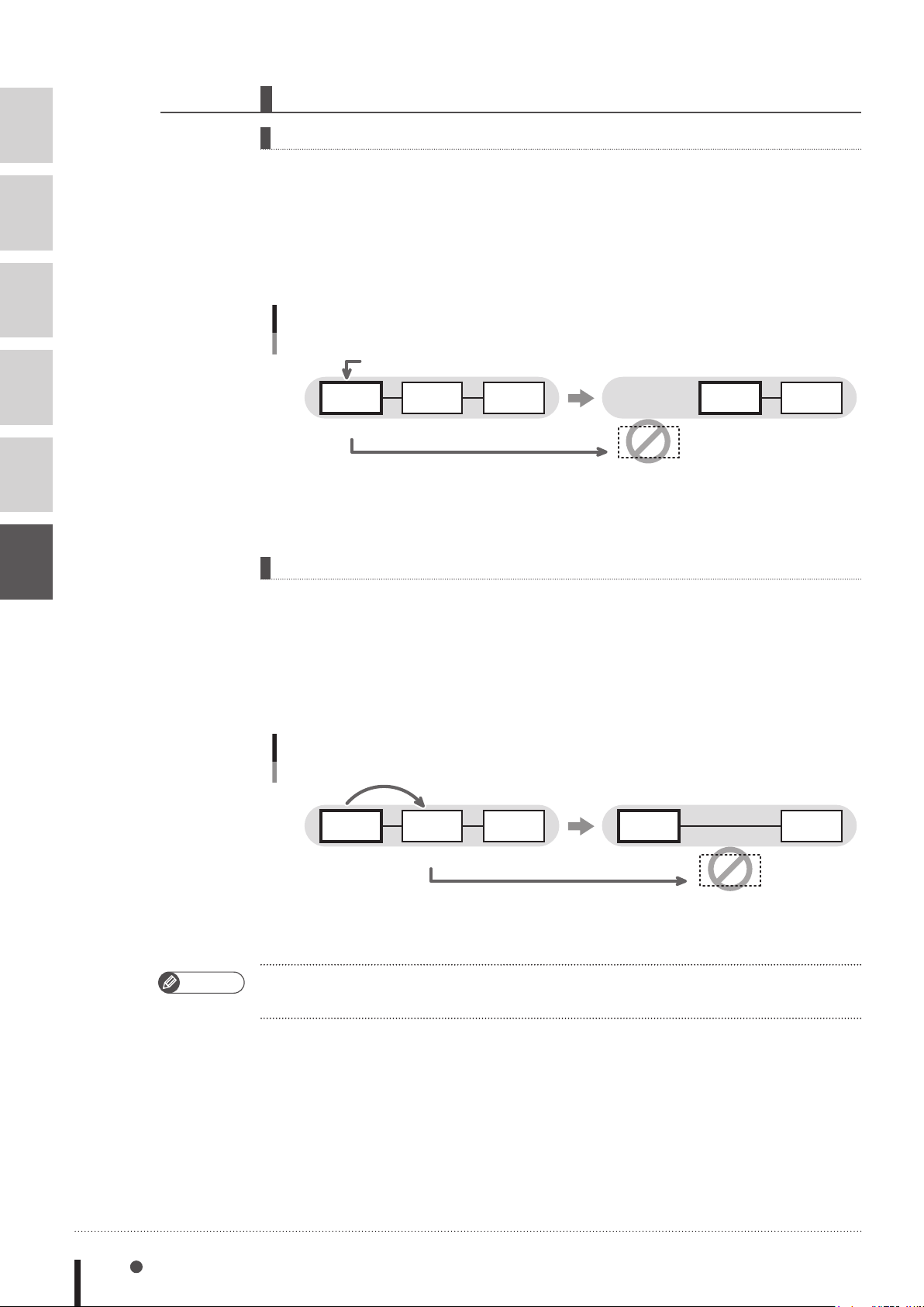
3.6 Deleting tasks
and is removed from a ready queue.
and is removed from the ready queue.
1
2
3
4
5
6
Task self-delete (EXIT TASK)
Tasks can delete themselves and set to the NON EXISTENT (no task registration) status by using the
EXIT TASK command.
When the EXIT TASK command is executed, the status transition takes place as follows.
■
Task that executed the EXIT TASK command
■
Task at the head of the ready queue with higher priority → RUN status
NON EXISTENT status
→
Task self-delete (EXIT TASK)
EXIT TASK
Task 2 Task 3
RUN READY
The task is placed in a NON EXISTENT status,
Task 4
READY
Task 2
NON EXISTENT
Task 3
RUN
Task 4
READY
33606-R7-00
Other-task delete (CUT)
MEMO
Tasks can also delete the other tasks and put in the NON EXISTENT (no task registration) status by
using the CUT command.
When the CUT command is executed, the status transition takes place as follows.
■
Task that executed the CUT command
■
Specified task
RUN
→
NON EXISTENT
→
Other-task delete (CUT)
CUT
Task 2 Task 3 Task 2
RUN READY
The task is placed in a NON EXISTENT status,
Task 4
READY RUN
Task 3
NON EXISTENT
Task 4
READY
33607-R7-00
• If a SUSPEND command is executed for a WAIT-status task, the commands being executed by
that task are ended.
6-6 Chapter 6 Multi-tasking
Page 73
3.7 Stopping tasks
All tasks stop if any of the following cases occurs.
1. HALTALL command is executed. (stop & reset)
All programs are reset and task is put in the NON EXISTENT status. When the main
program is specified, the HALTALL command registers the main program in the task 1 and all
tasks are put in the STOP status at the beginning line. When the main program is not specified,
the HALTALL command registers the program that has been executed last (current program) in
the task 1 and all tasks are put in the STOP status at the beginning line.
2. HOLDALL command is executed. (temporary stop)
All tasks are put in the STOP status. When the program is restarted, the tasks in the STOP status
set to the READY or SUSPEND status.
3. STOP key on the programming box is pressed or the interlock signal is cut off.
Just as in the case where the HOLD command is executed, all tasks are put in the STOP status.
When the program is restarted, the tasks in the STOP status set to the READY status (or, the task
is placed the SUSPEND status after being placed in the READY status).
4. When the emergency stop button on the programming box is pressed
or the emergency stop signal is cut off.
All tasks are put in the STOP status. At this point, the power to the robot is shut off and the
servo sets to the non-hold state.
After the canceling emergency stop, when the program is restarted, the tasks in the STOP status
are set to the READY or SUSPEND status. However, a servo ON is required in order to restart
the robot power supply.
1
2
3
4
5
6
MEMO
• When the program is restarted without being reset after the tasks have been stopped by a cause
other than 1., then each task is processed from the status in which the task stopped. This holds
true when the power to the controller is turned off and then turned on.
Task status and transition 6-7
Page 74
1
2
3
4
5
6
4
Multi-task program example
Tasks are executed in their scheduled order. An example of a multi-task program is shown below.
SAMPLE
’TASK1
START <SUB_TSK2>,T2
START <SUB_TSK3>,T3
*ST1:
DO(20) = 1
WAIT MO(20) = 1
MOVE P,P1,P2,Z=0
IF MO(21)=1 THEN *FIN
GOTO *ST1
*FIN:
CUT T2
HALTALL
Program name:SUB_TSK2
’TASK2 ····················· Task 2 begins here.
*ST2:
IF DI(20) = 1
MO(20) = 1
DELAY 100
ELSE
MO(20) = 0
ENDIF
GOTO *ST2
EXIT TASK Ends here.
Program name:SUB_TSK3
’TASK3 ····················· Task 3 begins here.
*ST3:
IF DI(21) = 0 THEN *ST3
IF DI(30) = 0 THEN *ST3
IF DI(33) = 0 THEN *ST3
MO(21) = 1
EXIT TASK ····················· Ends here.
5
Sharing the data
All global variables, static variables, input/output variables, point data, shift coordinate definition
data, hand definition data, and pallet definition data are shared between all tasks.
Execution of each task can be controlled while using the same variables and data shared with the
other tasks.
MEMO
• In this case, however, use sufficient caution when rewriting the variable and data because
improper changes may cause trouble in the task processing. Take great care when sharing the
same variables and data.
6-8 Chapter 6 Multi-tasking
Page 75

6
Cautionary Items
1
A freeze may occur if subtasks are continuously started (START command) and ended (EXIT TASK
command) by a main task in an alternating manner.
This occurs for the following reason: if the main task and subtask priority levels are the same, a task
transition to the main task occurs during subtask END processing, and an illegal task status then
occurs when the main task attempts to start a subtask.
Therefore, in order to properly execute the program, the subtask priority level must be set higher
than that of the main task. This prevents a task transition condition from occurring during execution
of the EXIT TASK command.
In the sample program shown below, the priority level of task 1 (main task) is set as 32, and the
priority level of task 2 is set as 31 (the lower the value, the higher the priority).
2
3
SAMPLE
FLAG1 = 0
*MAIN_TASK:
IF FLAG1=0 THEN
FLAG1 = 1
at the priority level of 31.
ENDIF
GOTO *MAIN_TASK
HALTALL
Program name:SUB_PGM
'==============
' TASK2
'==============
*TASK2:
DRIVE(1,P1)
WAIT ARM(1)
DRIVE(1,P2)
WAIT ARM(1)
FLAG1 = 0
EXIT TASK
START
<SUB_PGM>,T2,31
·········
<SUB_PGM> is started as task 2
4
5
6
Cautionary Items 6-9
Page 76

Page 77

Chapter 7
Sequence function
1 1
Sequence function ...................................
2 2
Creating a sequence program ...............
3 3
Executing a sequence program .............
4 4
Programming a sequence program ......
7-1
7-1
7-4
7-5
Page 78

Page 79
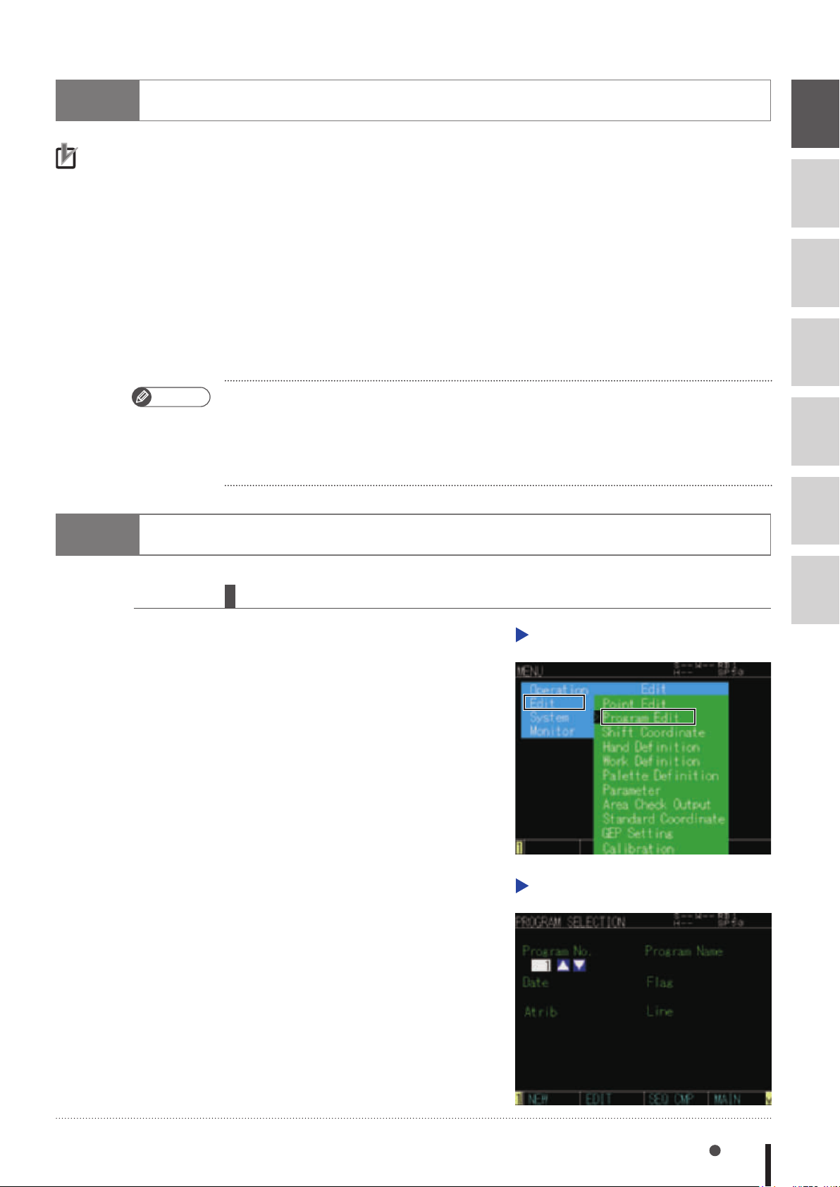
1
•While the "DI10: sequence
•The "DO12: Sequence
Sequence function
NOTE
control input" is ON, a
sequence program runs
according to its own
cycle, regardless of robot
program starts and stops.
program running"
signal output occurs while
a sequence program is
being executed.
dedicated
Besides normal robot programs, the YRCX controller can execute high-speed processing programs
(sequence programs) in response to the robot input/output (DI, DO, MO, LO, TO, SI, SO) signals.
• This function allows to monitor the input/output signals of sensors, push button switches, solenoid
valves, etc. and move them. The sequence program starts running simultaneously the controller is
turned on.
• The sequence program can be written in the same robot language used for robot programs. (The
ladder logic are not necessary).
• Naming the program "SEQUENCE" makes the controller recognize as sequence program.
• For details regarding conditions to execute a sequence program, refer to "3 Executing a sequence
program" in this Chapter.
• General-purpose outputs are not reset by the program reset while the sequence function is running.
7
8
9
10
MEMO
In the manner shown below, the reset of general-purpose output can be set while the sequence
program compile.
• Set a sequence flag value of the controller parameter at "3".
• Select "Output Reset Enable" on the sequence execution flag dialogue in the support software
"SCARA-YRCX Studio".
11
12
2
Creating a sequence program
2.1 Programming method
Step 1
Select [Program Edit] from [Edit]
menus on the "MENU" screen of
the programming box.
34701-R9-00
Step 1
13
Program edit
Step 2
Press the F1 key (NEW) on the
"PROGRAM SELECTION" screen.
34702-R9-00
Step 2
Program selection
Sequence function 7-1
Page 80
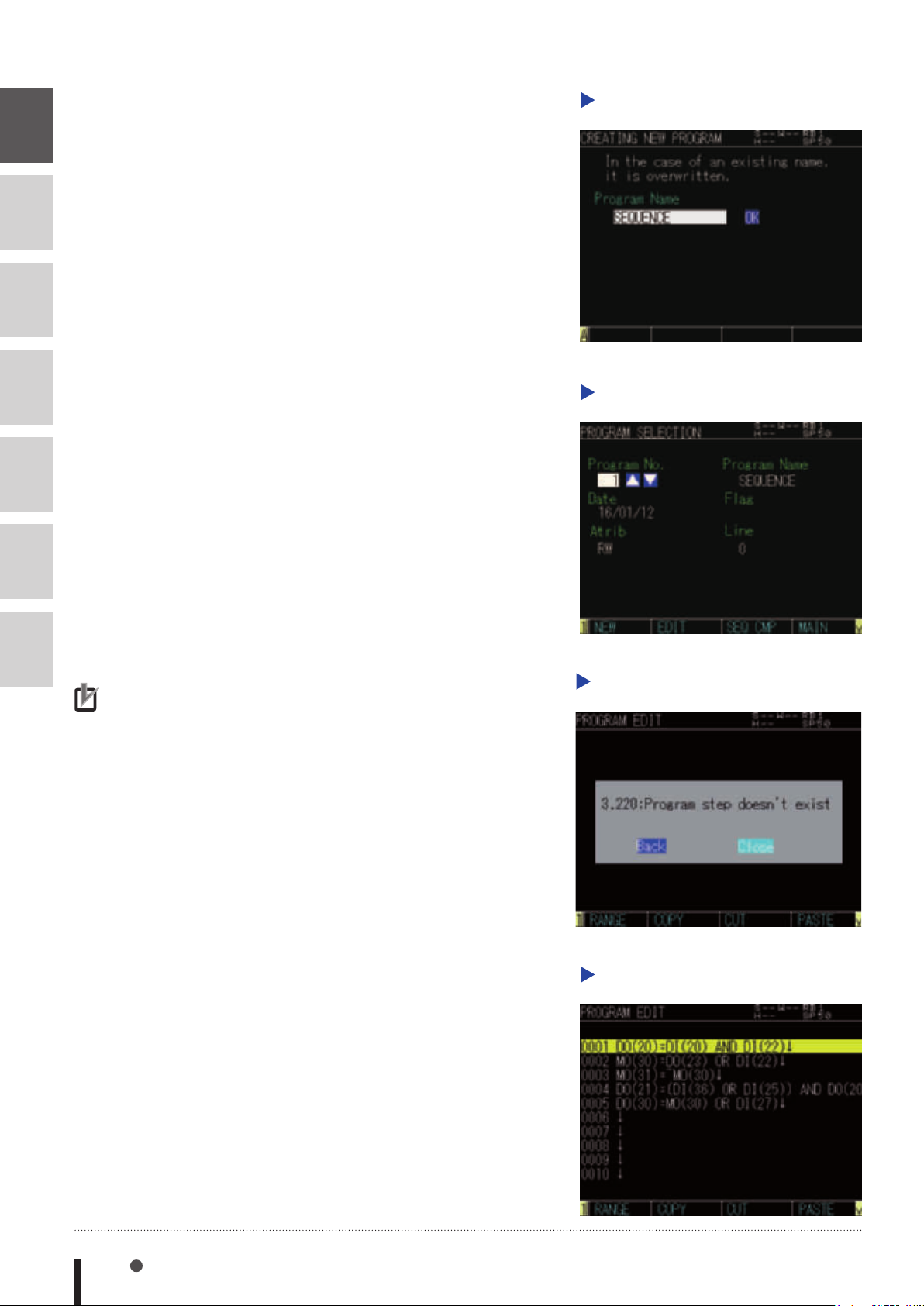
7
8
9
Step 3
Enter "SEQUENCE" on the
program name entry screen, and
press the [OK] button.
34703-R9-00
Step 3
Creating new program
10
11
12
13
NOTE
•When creating a new
program, the alarm
occurs since no program
is written. This alarm does
not occur when the robot
language exists already in
a program.
Step 4
Step 5
Use the cursor keys (s/t) to
select "SEQUENCE" on the
"PROGRAM SELECTION" screen,
and then press the F2 key (EDIT).
34704-R9-00
"3.220: Program step doesn't
exist" message appears when
creating a new program, and
press [Close].
34705-R9-00
Step 4
Step 5
Program selection
“Program step doesn’t exist” message
Step 6
7-2 Chapter 7 Sequence function
Input a program on "PROGRAM
SELECTION" screen.
Although usable commands are
resricted, editing method is same
as the standard robot program.
Commands which can be input
are explained at "4 Programming
a sequence program" in this
Chapter.
34706-R9-00
Step 6
Program edit
Page 81
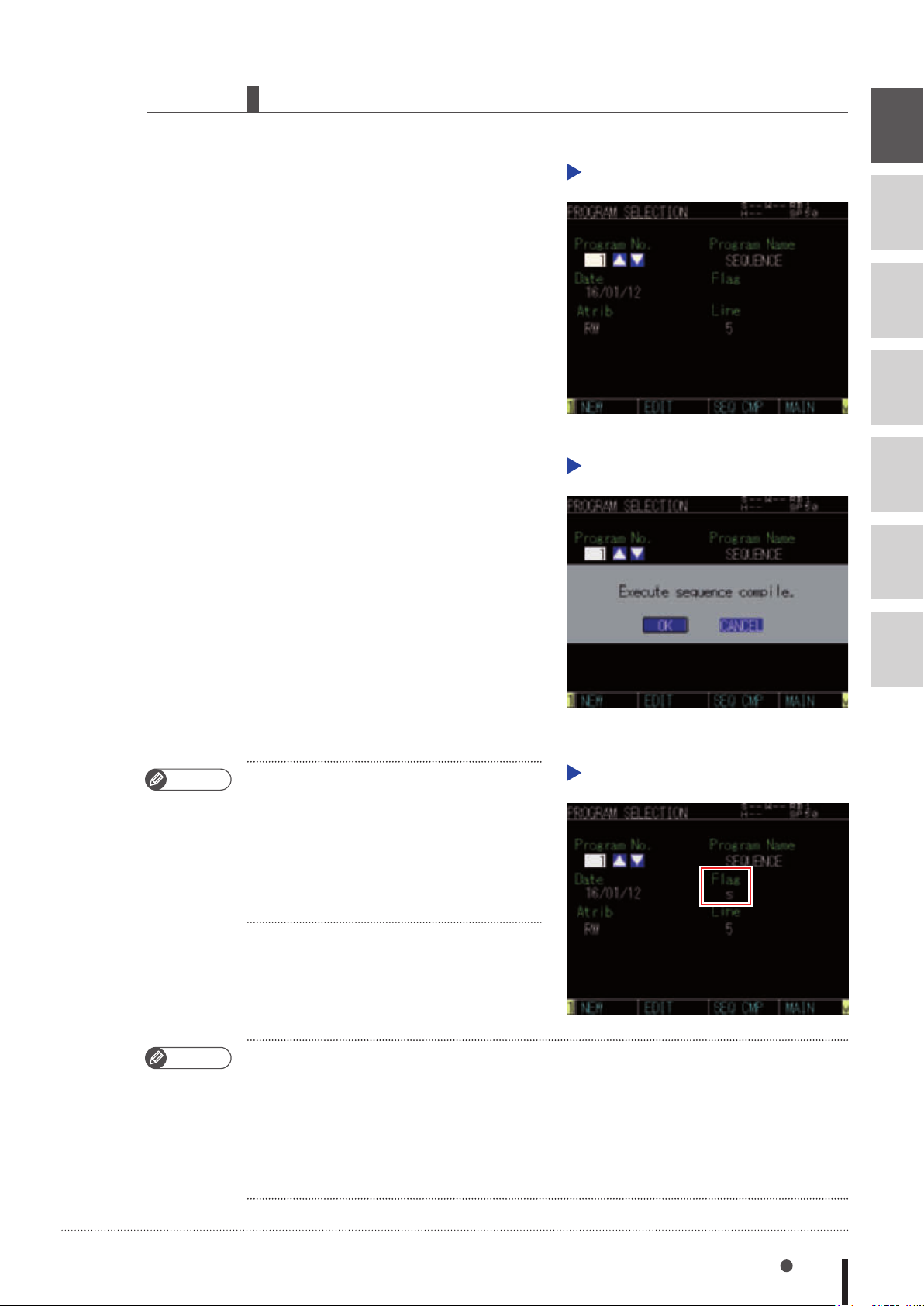
2.2 Compiling
Compile and create an executable sequence program.
Step 1
Step 2
Press the F3 key (SEQ CMP) on
the "PROGRAM SELECTION"
screen.
34707-R9-00
The confirmation message will
appear whether you execute
sequence compile.
Press [OK] to compile the
program.
34708-R9-00
Step 1
Step 2
7
Program selection
8
9
10
Sequence compiling
11
12
MEMO
MEMO
• If there is a syntax error in the program, an
error message appears. When the compiling
ends without any error, the display returns to
the "PROGRAM SELECTION" screen and the
letter "s" appears in "Flag". This means that
the sequence program has been compiled
successfully and is ready for use.
34709-R9-00
• The sequence execution program is erased and the Flag's letter "s" disappears in the following
cases. In these cases the sequence function cannot be used.
1. When the sequence program was erased.
2. When the sequence program was edited.
3. When the program data was initialized.
4. When the "9.729: Sequence object destroyed." alarm occured.
MEMO
Success of compiling
13
Creating a sequence program 7-3
Page 82
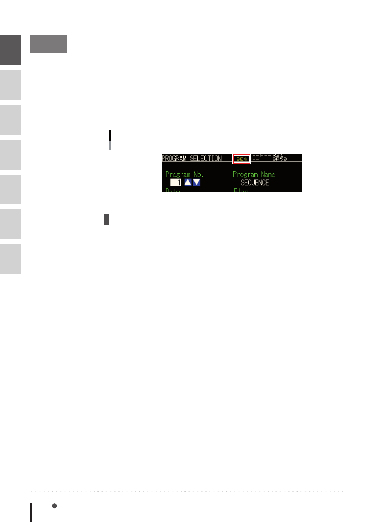
7
8
9
10
3
Executing a sequence program
All the following conditions must be satisfied to execute a sequence program.
1. The sequence program has been compiled.
2. The sequence program execution flag is enabled.
(For details regarding the sequence program execution flag, refer to the YRCX operator’s
manual.)
3. The external sequence control input (DI10) contact is ON.
Sequence program execution in progress
Indicated during execution
11
12
13
34710-R9-00
3.1 Sequence program STEP execution
The sequence program may be executed line by line while checking one command line at a time.
This step execution can be executed in the same way as normal programs.
For details, refer to the YRCX operator’s manual.
When the step is executed, satisfying the conditions described in the previous section is not
required.
7-4 Chapter 7 Sequence function
Page 83

4
Programming a sequence program
7
When programming a sequence program, you may use only assignment statements comprised of
input/output variables and logical operators.
4.1 Assignment statements
Format
output variable = expression
Values expression ............................. Any one of the following can be used.
• Parallel input/output variables
• Internal output variables
• Arm lock output variables
• Timer output variables
• Serial input/output variable
• The logic operation expression shown above
4.2 Input/output variables
Each variable must be specified in a 1-bit format
·Correct examples DO(35)
MO(24)
DI(16)
·Incorrect examples DO(37, 24)
DI3(4)
MO3()
8
9
10
11
12
13
4.2.1 Input variables
●Parallel input variables
Format
DI(mb) m: Port number ·············· 0 to 7, 10 to 17, 20 to 27
b: bit definition ············ 0 to 7
These variables show the status of the parallel input signal.
●Serial input variables
Format
SI(mb) m: Port number ·············· 0 to 7, 10 to 17, 20 to 27
b: bit definition ············ 0 to 7
Indicates a serial input signal status. Only referencing can occur. No controls are possible.
Programming a sequence program 7-5
Page 84
4.2.2 Output variables
7
8
9
10
11
12
●Parallel output variables
Format
DO(mb) m: Port number ·············· 0 to 7, 10 to 17, 20 to 27
b: bit definition ············ 0 to 7
A parallel output is specified, or the output status is referenced. Ports 0 and 1 are for referencing
only, and no outputs can occur there.
●Internal output variables
Format
MO(mb) m: Port number ··············
b: bit definition ············ 0 to 7
These variables are used within the controller. Ports 30 to 37 are for referencing only
and ON/OFF can not be controlled.
●Arm lock output variables
Format
LO(mb) m: port number ·············· 0, 1
b: bit definition ················ 0 to 7
0 to 7, 10 to 17, 20 to 27, 30 to 37
13
These variables are used to prohibit the arm (axis) movement. Movement is prohibited when ON.
LO(00) to LO(07) corresponds to arm 1 to arm 8, LO(10) to LO(17) corresponds to arm 9 to
arm 16, respectively.
●Timer output variables
Format
TO(mb) m: port number ·············· 0, 1
b: bit definition ············ 0 to 7
There are a total of 16 timer output variables: TO(00) to TO(17). The timer of each variable is
defined by the timer definition statement TIM00 to 17.
●Serial output variables
Format
SO(mb) m: Port number ·············· 0 to 7, 10 to 17, 20 to 27
b: bit definition ············ 0 to 7
Control or reference serial output signal status. Port 0 is for referencing only,
and no controls are possible.
7-6 Chapter 7 Sequence function
Page 85
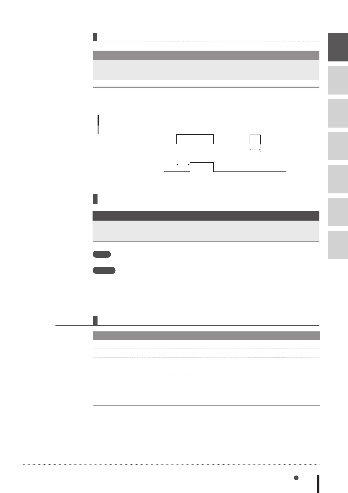
Timer usage example
TO(02)
SAMPLE
TIM02 = 2500 ···················· Timer 02 is set to 2.5 seconds.
TO(02) = DI(23) ················· Timer starts when DI(23) switches ON.
• When DI(23) is ON, after 2.5 seconds, TO(02) is set ON.
• When DI(23) is OFF, TO(02) is also OFF.
• When DI(23) isn’t ON after 2.5 second or more, TO(02) does not change to ON.
Timer usage example: Timing chart
DI(23)
2.5sec
4.3 Timer definition statement
Format
1.6sec
33701-R7-00
7
8
9
10
11
12
TIMmb=time m: Port number ······· 0, 1
b: bit definition ····· 0 to 7
Values time ...................................... 100 to 999,900ms (0.1 to 999.9 second)
Meaning The timer definition statement sets the timer value of the timer output variable. This
definition statement may be anywhere in the program.
When the timer definition statement is omitted, the timer setting value of the variable is 0.
TIM00 to 17 correspond to the timer output variables TO(00) to (17).
However, since the units are set every 100ms, values less than 99ms are truncated.
4.4 Logical operators
Operators Functions Meaning
NOT, ~ Logical NOT Reverses the bits.
AND, & Logical AND Becomes "1" when both bits are "1".
OR, | Logical OR Becomes "1" when either of the bits is "1".
XOR Exclusive OR Becomes "1" when both bits are different.
EQV Logical equivalence
operator
IMP Logical implication
operator
13
Becomes "1" when both bits are equal.
Becomes "0" when the rst bit is "1" and the second
bit is "0".
Programming a sequence program 7-7
Page 86
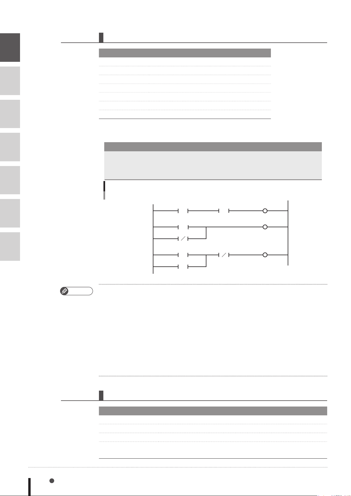
4.5 Priority of logic operations
7
8
9
10
11
12
Priority Ranking Operation Content
1 Expressions in parentheses
2 NOT, ~ (Logical NOT)
3 AND, & (Logical AND)
4 OR, | (Logical OR)
5 XOR (Exclusive OR)
6 EQV (Logical equivalence operator)
7 IMP (Logical implication operator)
●Example with a ladder statement substitution
SAMPLE
DO(23)=DI(16)&DO(35)
MO(34)=DO(25) | ~DI(24)
DO(31)=(DI(20) | DO(31))&~DI(21)
Ladder diagram
DI(16)
DO(25)
DO(35)
DO(23)
MO(34)
13
~
DI(24)
DI(20)
DO(31)
MEMO
• "NOT" cannot be used prior to the first parenthesis " ( " or on the left of an expression. For
example, the following commands cannot be used.
•DO(21)=~(DI(30) | DI(32))
•~DO(30)=DI(22)&DI(27)
• Numeric values cannot be assigned on the right of an expression.
•MO(35)=1
•DO(26)=0
• There is no need to define a "HALT" or "HOLD" statement at the end of the program.
• The variables used in sequence programs are shared with robot programs, so be careful not to
make improper changes when using the same variables between them.
4.6 Sequence program specifications
~
DI(21)
DO(31)
(Self-hold circuit)
33702-R7-00
Item Specication
Commands Logical NOT, AND, OR, XOR, EQV, IMP
I/O Same as robot language
Program capacity 16,384 bytes (A maximum of 2,048 variables can be specied.)
Scan time 1 to 4ms depending on the number of steps (This changes
7-8 Chapter 7 Sequence function
automatically.)
Page 87

Chapter 8
Robot Language Lists
How to read the robot language table ..........
Command list in alphabetic order ..................
Operation-specific ...........................................
Functions: in alphabetic order ......................
Functions: operation-specific ........................
1 1
ABS ......................................................
2 2
ABSRPOS .............................................
3 3
ACCEL .................................................
4 4
ARCHP1 / ARCHP2 ..............................
5 5
ARMCND .............................................
6 6
ARMSEL ................................................
7 7
ARMTYP ...............................................
8 8
ASPEED ................................................
9 9
ATN / ATN2 ..........................................
8-1
8-2
8-7
8-13
8-16
8-18
8-19
8-20
8-21
8-23
8-24
8-25
8-26
8-27
10 10
11 11
12 12
13 13
14 14
15 15
AXWGHT ..............................................
CALL .....................................................
CHANGE ..............................................
CHGPRI ................................................
CHR$ ....................................................
CLOSE ..................................................
8-28
8-29
8-30
8-31
8-32
8-33
Page 88

16 16
COS .....................................................
8-34
17 17
18 18
19 19
20 20
21 21
22 22
23 23
24 24
25 25
26 26
27 27
28 28
29 29
30 30
CURTQST ..............................................
CURTRQ ...............................................
CUT ......................................................
DATE$ ...................................................
DECEL ..................................................
DEF FN ..................................................
DEGRAD ..............................................
DELAY ..................................................
DI .........................................................
DIM ......................................................
DIST ......................................................
DO .......................................................
DRIVE ...................................................
DRIVEI ..................................................
8-35
8-36
8-37
8-38
8-39
8-40
8-41
8-42
8-43
8-44
8-45
8-46
8-48
8-52
31 31
32 32
33 33
34 34
35 35
36 36
37 37
38 38
39 39
40 40
41 41
42 42
43 43
44 44
END SELECT ..........................................
END SUB ...............................................
ERR / ERL ..............................................
ETHSTS ..................................................
EXIT FOR ..............................................
EXIT SUB ...............................................
EXIT TASK .............................................
FOR to NEXT ........................................
GEPSTS .................................................
GOSUB to RETURN ...............................
GOTO ...................................................
HALT .....................................................
HALTALL ...............................................
HAND ...................................................
8-57
8-58
8-59
8-60
8-61
8-62
8-63
8-64
8-65
8-66
8-67
8-68
8-69
8-70
45 45
46 46
47 47
48 48
49 49
50 50
HOLD ...................................................
HOLDALL ..............................................
IF ..........................................................
INPUT ....................................................
INT ........................................................
JTOXY ..................................................
8-73
8-74
8-75
8-77
8-79
8-80
Page 89

51 51
LEFT$ ....................................................
8-81
52 52
53 53
54 54
55 55
56 56
57 57
58 58
59 59
60 60
61 61
62 62
63 63
64 64
65 65
LEFTY ....................................................
LEN .......................................................
LET ........................................................
LO ........................................................
LOCx ....................................................
LSHIFT ...................................................
MCHREF ...............................................
MID$ ....................................................
MO .......................................................
MOTOR ................................................
MOVE ...................................................
MOVEI ................................................
MOVET ...............................................
MTRDUTY ............................................
8-82
8-83
8-84
8-87
8-89
8-91
8-92
8-93
8-94
8-96
8-97
8-112
8-122
8-132
66 66
67 67
68 68
69 69
70 70
71 71
72 72
73 73
74 74
75 75
76 76
77 77
78 78
79 79
OFFLINE .............................................
ON ERROR GOTO ..............................
ON to GOSUB ....................................
ON to GOTO ......................................
ONLINE ..............................................
OPEN .................................................
ORD ...................................................
ORGORD ...........................................
ORIGIN ..............................................
OUT ....................................................
OUTPOS .............................................
PATH ...................................................
PATH END ...........................................
PATH SET .............................................
8-133
8-134
8-135
8-136
8-137
8-138
8-139
8-140
8-141
8-142
8-143
8-145
8-151
8-152
80 80
81 81
82 82
83 83
84 84
85 85
PATH START ........................................
PDEF ...................................................
PGMTSK .............................................
PGN ...................................................
PMOVE ...............................................
Pn .......................................................
8-155
8-159
8-160
8-161
8-162
8-166
Page 90

86 86
PPNT ...................................................
8-168
87 87
88 88
89 89
90 90
91 91
92 92
93 93
94 94
95 95
96 96
97 97
98 98
99 99
100 100
PRINT ..................................................
PSHFRC ..............................................
PSHJGSP ............................................
PSHMTD .............................................
PSHRSLT ..............................................
PSHSPD ..............................................
PSHTIME .............................................
PUSH ..................................................
RADDEG ............................................
REM ....................................................
RESET ..................................................
RESTART .............................................
RESUME ..............................................
RETURN ...............................................
8-169
8-170
8-171
8-172
8-173
8-174
8-175
8-176
8-181
8-182
8-183
8-184
8-185
8-186
101 101
102 102
103 103
104 104
105 105
106 106
107 107
108 108
109 109
110 110
111 111
112 112
113 113
114 114
RIGHT$ ...............................................
RIGHTY ...............................................
RSHIFT ................................................
SELECT CASE to END SELECT .............
SEND ..................................................
SERVO ................................................
SET ......................................................
SETGEP ...............................................
SGI .....................................................
SGR ....................................................
SHARED ..............................................
SHIFT ..................................................
SI ........................................................
SID ......................................................
8-187
8-188
8-189
8-190
8-191
8-193
8-194
8-195
8-196
8-197
8-198
8-199
8-200
8-201
115 115
116 116
117 117
118 118
119 119
SIN .....................................................
SIW .....................................................
Sn .......................................................
SO ......................................................
SOD ....................................................
8-202
8-203
8-204
8-205
8-207
Page 91

120 120
SOW ...................................................
8-208
121 121
122 122
123 123
124 124
125 125
126 126
127 127
128 128
129 129
130 130
131 131
132 132
133 133
134 134
SPEED .................................................
SQR ....................................................
START .................................................
STR$ ....................................................
SUB to END SUB .................................
SUSPEND ............................................
SWI .....................................................
TAN ....................................................
TCOUNTER .........................................
TIME$ .................................................
TIMER .................................................
TO .......................................................
TOLE ...................................................
TORQUE .............................................
8-209
8-210
8-211
8-212
8-213
8-215
8-216
8-217
8-218
8-219
8-220
8-221
8-222
8-223
135 135
136 136
137 137
138 138
139 139
140 140
141 141
142 142
143 143
144 144
TSKPGM .............................................
VAL .....................................................
WAIT ...................................................
WAIT ARM ..........................................
WEIGHT ..............................................
WEND .................................................
WHERE ................................................
WHILE to WEND .................................
WHRXY ...............................................
XYTOJ ................................................
8-225
8-226
8-227
8-228
8-229
8-230
8-231
8-232
8-233
8-234
Page 92

Page 93
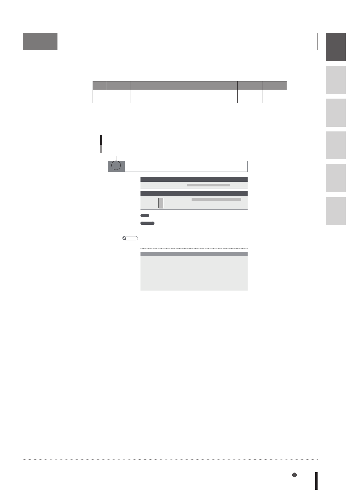
How to read the robot language table
The key to reading the following robot language table is explained below.
(1) (2) (3) (4)
| | | |
No. Name Description Online Type
8
9
26 DIM
Declares array variable
-
Command
(1) No.
Indicates the Item No. where this robot language is explained in detail.
Example of "No." column
No.
26 DIM
Declares array variable
Format
array definition ,array definition
DIM
Format
name
constant
Values
Explanation Directly declares the name and length (number of elements) of an array variable. A
• Array subscripts can be "0 to a specified value", with their total number being the
MEMO
• A "9.300: Memory full" error may occur depending on the size of each dimension in an
array.
SAMPLE
DIM A%(10) ・・・・・・・・・・・・・・・・・・・・・・・・ D e f i ne s a i n t e g er a r r a y
DIM B(
DIM C%(
constant, constant
% (
!
$
............................Array subscript: 0 to 32,767 (positive integer)
maximum of 3 dimensions may be used for the array subscripts. Multiple arrays can
be declared in a single line by using comma ( , ) to separate.
vari able A % (
2,3,4) ・・・・・・・・・・・・・・・・・・・・・ Defines a real array variable
2,2),D!(10) ・・・・・・・・・・・・ Defi nes a n int eger arra y C%
(Number of elements:
B (
0, 0, 0) to B (2, 3, 4).
(Number of elements:
(
0,0) to C% (2,2) and a real
array D! (
0) t o A% (10).
0) to D! (10).
,
,…
constant
constant
defined
11).
60).
)
+ 1.
(2) Description
Explains the function of the robot language.
(3) Online
If "3" is indicated at this item, online commands can be used.
If "-" is indicated at this item, commands containing operands that cannot partially be
executed by online command.
(4) Type
Indicates the robot language type as "Command" or "Function".
When a command is used as both a "Command" and "Function", this is expressed as follows:
Command/Function
10
11
12
13
How to read the robot language table 8-1
Page 94
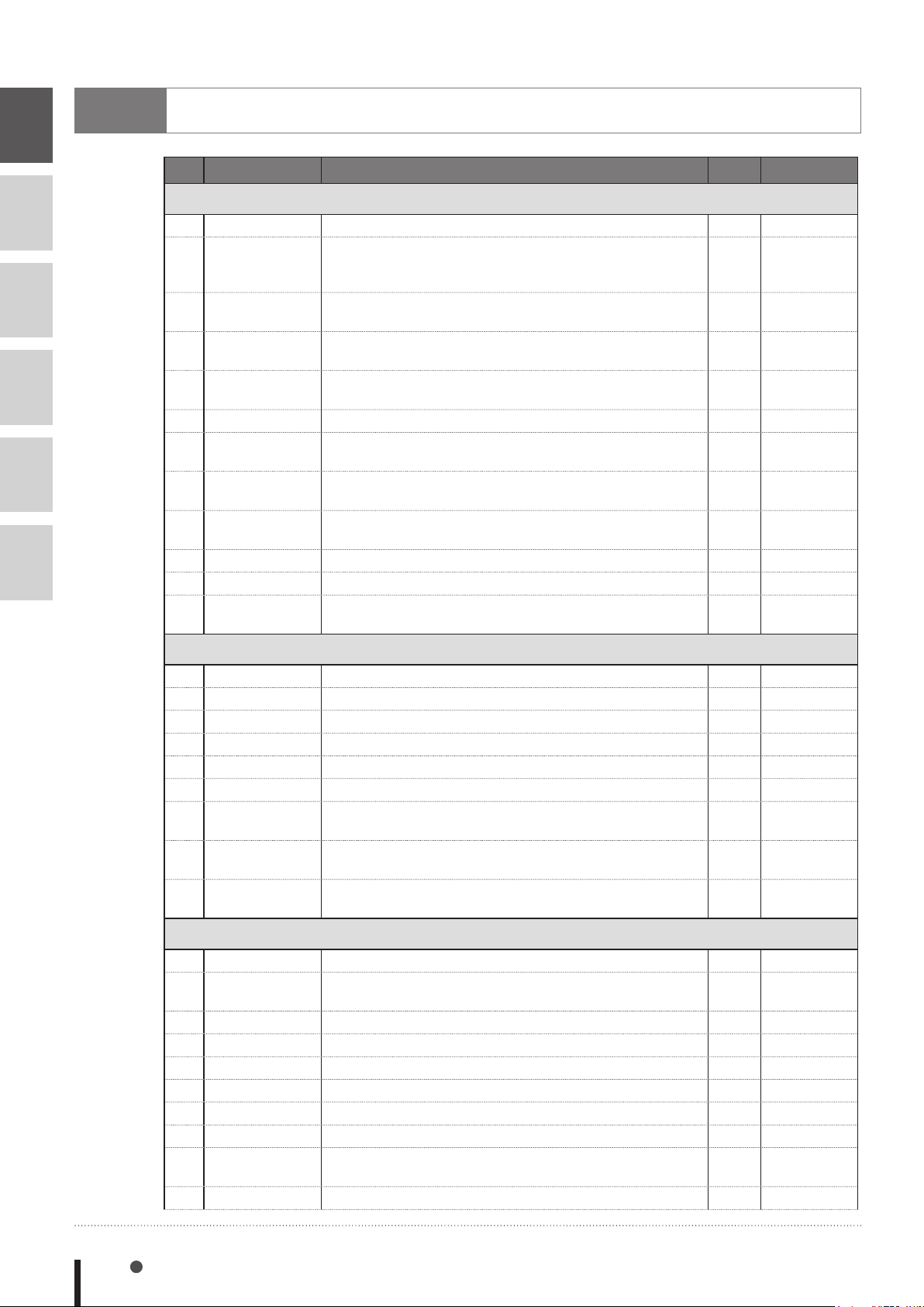
8
9
10
11
12
13
Command list in alphabetic order
No. Name Description Online Type
A
1 ABS Acquires the absolute value of a specied value.
Acquires the machine reference value for specified robot
2 ABSRPOS
3 ACCEL
4 ARCHP1
4 ARCHP2
5 ARMCND Acquires the current arm status of a specied robot.
6 ARMSEL
7 ARMTYP
8 ASPEED
9 ATN Acquires the arctangent of the specied value.
9 ATN2 Acquires the arctangent of the specied X-Y coordinates.
10 AXWGHT
axes. (Valid only for axes whose return-to-origin method is
set as "mark".)
Species/acquires the acceleration coefcient parameter of
a specied robot.
Specifies/acquires the arch position 1 parameter of a
specied robot.
Specifies/acquires the arch position 2 parameter of a
specied robot.
Specifies/acquires
specied robot.
Species/acquires the "hand system" setting of a specied
robot.
Specifies/acquires the AUTO movement speed of a
specied robot.
Specifies/acquires the axis tip weight parameter of a
specied robot.
the current "hand system" setting of a
3
3
3
3
3
3
3
3
3
3
3
3
Function
Function
Command /
Function
Command /
Function
Command /
Function
Function
Command /
Function
Command /
Function
Command /
Function
Function
Function
Command /
Function
C
11 CALL Calls a sub-procedure.
12 CHANGE Switches the hand of a specied robot.
13 CHGPRI Changes the priority ranking of a specied task.
14 CHR$
15 CLOSE Close the
16 COS Acquires the cosine value of a specied value.
17 CURTQST
18 CURTRQ
19 CUT
Acquires a character with the specied character code.
specied General Ethernet Port.
Acquires the current torque value ratio of a specied axis to
the rated torque.
Acquires the current torque value of the specied axis of a
specied robot.
Terminates another task currently being executed or
temporarily stopped.
D
20 DATE$ Acquires the date as a "yy/mm/dd" format character string.
21 DECEL
22 DEF FN Denes the functions that can be used by the user.
23 DEGRAD Converts a specied value to radians (↔RADDEG).
24 DELAY Waits for the specied period (units: ms).
25 DI Acquires the specied DI status.
26 DIM
27 DIST Acquires the distance between 2 specied points.
28 DO
29 DRIVE
Specifies/acquires the deceleration rate parameter of a
specied robot.
Declares the array variable name and the number of elements.
Outputs a specied value to the DO port or acquires the DO
status.
Moves a specied axis of a specied robot to an absolute position.
-
3
3
3
3
3
3
3
3
3
3
-
3
-
3
-
3
3
3
Command
Command
Command
Function
Command
Function
Function
Function
Command
Function
Command /
Function
Command
Function
Command
Function
Command
Function
Command /
Function
Command
8-2 Chapter 8 Robot Language Lists
Page 95
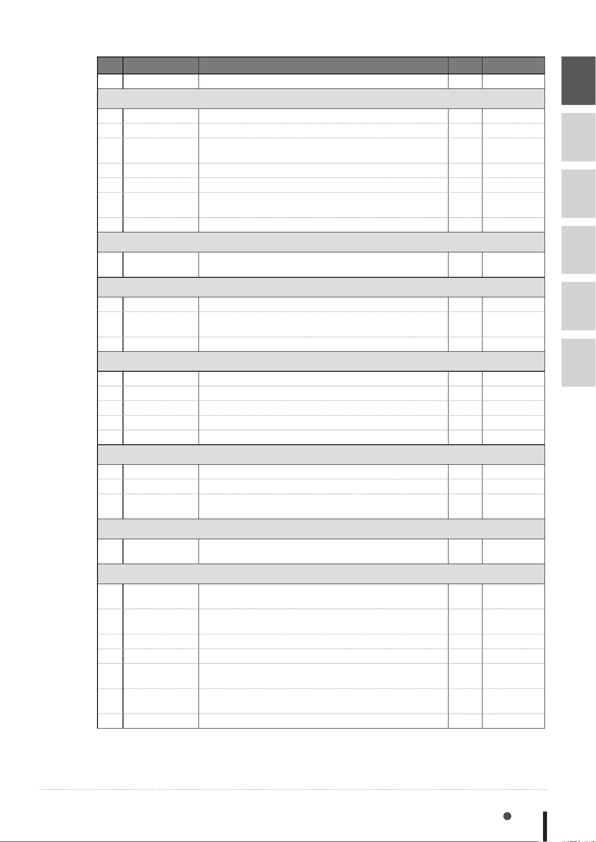
No. Name Description Online Type
30 DRIVEI
Moves a specied axis of a specied robot to a relative position.
3
Command
E
31 END SELECT Terminates the SELECT CASE statement.
32 END SUB Terminates the sub-procedure denition.
33 ERR / ERL
34 ETHSTS Acquires the Ethernet port status.
35 EXIT FOR Terminates the FOR to NEXT statement loop.
36 EXIT SUB
37 EXIT TASK Terminates its own task which is in progress.
Acquires
occurred / the line number
Terminates the sub-procedure dened by the SUB to END
statement.
the error code number of an error which has
where an error occurred
-
-
.
3
3
-
-
-
Command
Command
Function
Function
Command
Command
Command
F
38 FOR to NEXT
Executes the FOR to NEXT statement repeatedly until a
specied value is exceeded.
-
Command
G
39 GEPSTS Acquires the General Ethernet Port status.
GOSUB to
40
RETURN
41 GOTO Unconditionally jumps to the line specied by a label.
Jumps to a subroutine with the label specied by GOSUB
statement, and executes that subroutine.
3
-
-
Function
Command
Command
8
9
10
11
12
H
42 HALT Stops the program and performs a reset.
43 HALTALL Stops and resets all programs.
44 HAND Denes the hand of a specied robot.
45 HOLD Temporarily stops the program.
46 HOLDALL Temporarily stops all programs.
I
47 IF Allows control ow to branch according to conditions.
48 INPUT
49 INT
Assigns a value to a variable specied from the programming box.
Acquires an integer for a specified value by truncating all
decimal fractions.
J
50 JTOXY
Converts joint coordinate data to Cartesian coordinate data
of a specied robot. (↔XYTOJ)
L
51 LEFT$
52 LEFTY
53 LEN
54 LET Executes a specied assignment statement.
55 LO
56 LOCx
57 LSHIFT
Extracts a character string comprising a specied number
of digits from the left end of a specied character string.
Sets the hand system of a specied robot to the left-handed
system.
Acquires the length (byte count) of a specied character string.
Outputs a specied value to the LO port to enable/disable
axis movement or acquires the LO status.
Specifies/acquires point data for a specified axis or shift
data for a specied element.
Shifts a value to the left by the specied bit count. (↔RSHIFT)
-
-
3
-
-
-
3
3
3
3
3
3
3
3
3
3
13
Command
Command
Command
Command
Command
Command
Command
Function
Function
Function
Command
Function
Command
Command /
Function
Command /
Function
Function
Command list in alphabetic order 8-3
Page 96
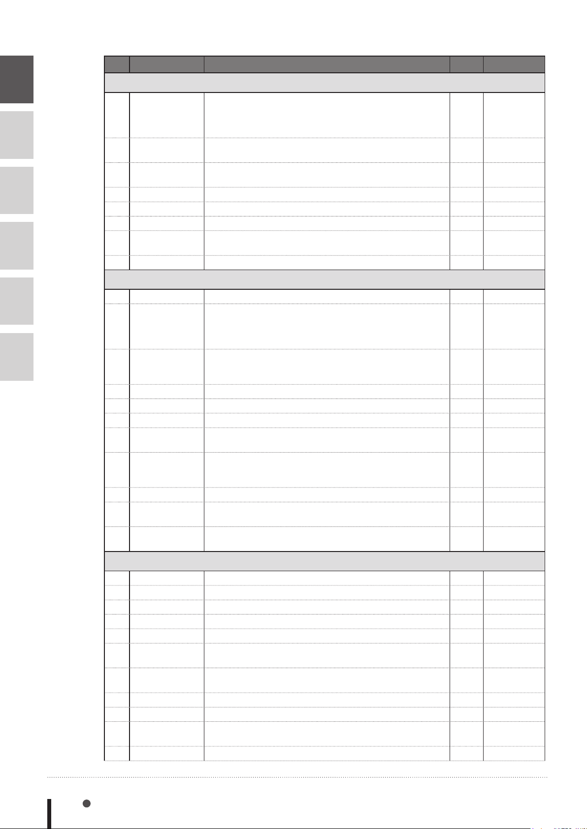
No. Name Description Online Type
8
9
10
11
12
13
M
Acquires the return-to-origin or absolute-search machine
58 MCHREF
59 MID$
60 MO
61 MOTOR Controls the motor power status.
62 MOVE
63 MOVEI Performs relative movement of all axes of a specied robot.
64 MOVET
65 MTRDUTY Acquires the motor load factor of the specied axis.
reference value for specied robot axes. (Valid only for axes
whose return-to-origin method is set as "sensor" or "strokeend".)
Extracts a character string of a desired length from a
specied character string.
Outputs a specified value to the MO port or acquires the
MO status.
Performs absolute movement of all axes of a specied robot.
Performs relative movement of all axes of a specied robot
when the tool coordinate is selected.
O
66 OFFLINE Sets a specied communication port to the "ofine" mode.
This command allows the program to jump to the error
ON ERROR
67
GOTO
68 ON to GOSUB
69 ON to GOTO
70 ONLINE Sets the specied communication port to the "online" mode.
71 OPEN Opens the specied General Ethernet Port.
72 ORD
73 ORGORD
74 ORIGIN Performs return-to-origin.
75 OUT
76 OUTPOS
processing routine specified by the label without stopping
the program, or it stops the program and displays the error
message.
Jumps to a subroutine with labels specified by a GOSUB
statement in accordance with the conditions, and executes
that subroutine.
Jumps to label-specied lines in accordance with the conditions.
Acquires the character code of the first character in a
specied character string.
Specifies/acquires the axis sequence parameter for
performing return-to-origin and an absolute search
operation in a specied robot.
Turns ON the bits of the specified output ports and
terminates the command statement.
Specifies/acquires the "OUT position" parameter of a
specied robot.
3
3
3
3
3
3
3
3
3
-
-
-
3
3
3
3
3
-
3
Function
Function
Command /
Function
Command
Command
Command
Command
Function
Command
Command
Command
Command
Command
Command
Function
Command /
Function
Command
Command
Command /
Function
P
77 PATH Species the PATH motion path.
78 PATH END Ends the path setting for PATH motion.
79 PATH SET Starts the path setting for PATH motion.
80 PATH START Starts the PATH motion.
81 PDEF
82 PGMTSK
83 PGN
84 PMOVE
85 Pn Denes points within a program.
86 PPNT
87 PRINT Displays a character string at the programming box screen.
8-4 Chapter 8 Robot Language Lists
Denes the pallet used to execute pallet movement commands.
Acquires the task number in which a specied program is
registered.
Acquires the program number from a specified program
name.
Executes the pallet movement command of a specied robot.
Creates point data specified by a pallet definition number
and pallet position number.
-
-
-
-
3
3
3
3
3
3
-
Command
Command
Command
Command
Command
Function
Function
Command
Command
Function
Command
Page 97
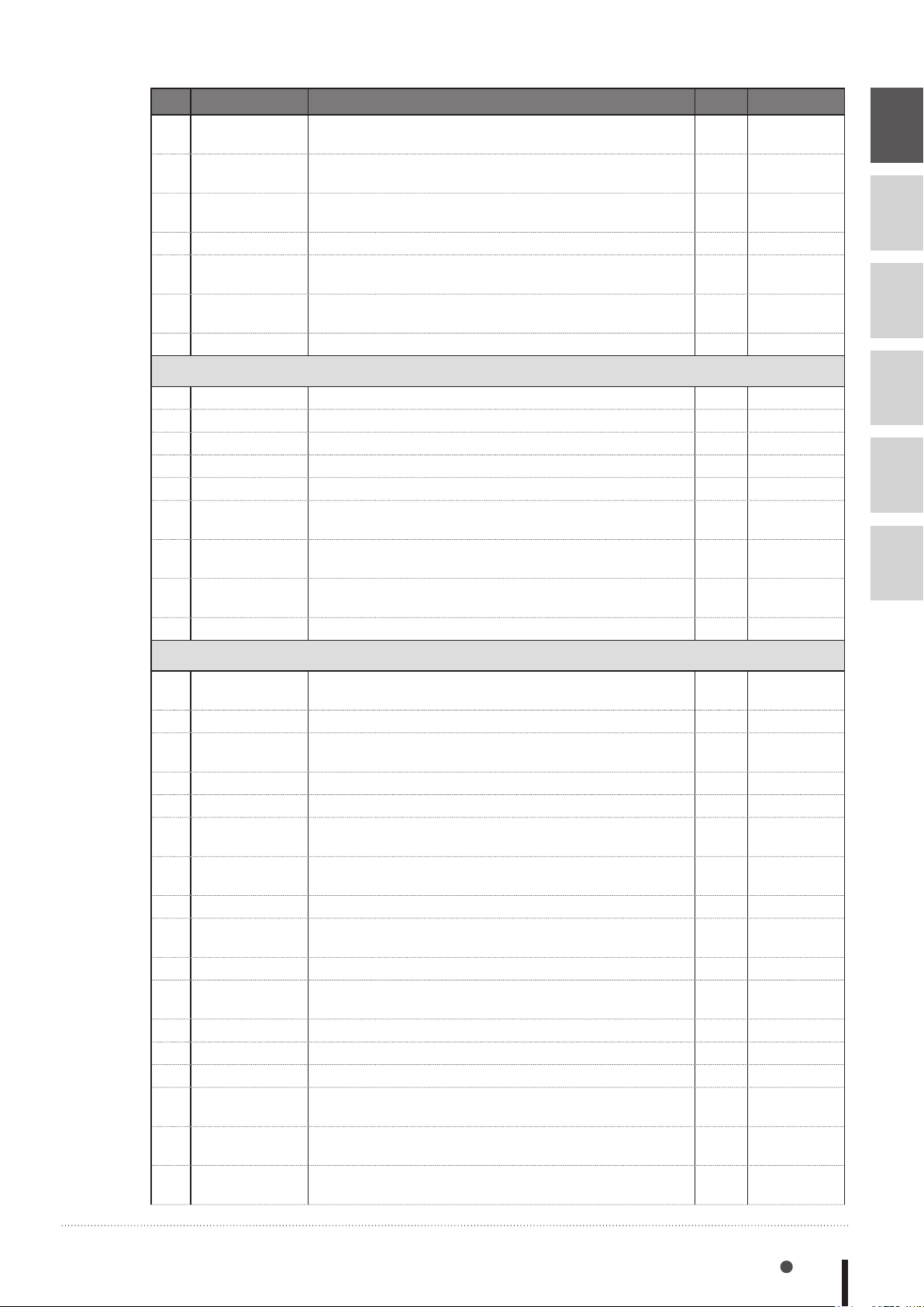
No. Name Description Online Type
88 PSHFRC Species/acquires the "Push force" parameter.
89 PSHJGSP
90 PSHMTD Species/acquires the push method parameter.
91 PSHRSLT Acquires the status at the end of the PUSH statement.
92 PSHSPD Species/acquires the push speed parameter.
93 PSHTIME Species/acquires the push time parameter.
94 PUSH Executes a pushing operation in the axis unit.
Specifies/acquires the push judge speed threshold
parameter.
3
3
3
3
3
3
3
Command /
Function
Command /
Function
Command /
Function
Function
Command /
Function
Command /
Function
Command
R
95 RADDEG Converts a specied value to degrees. (↔DEGRAD)
96 REM Expresses a comment statement.
97 RESET Turns the bit of a specied output port OFF.
98 RESTART Restarts another task during a temporary stop.
99 RESUME
100 RETURN
101 RIGHT$
102 RIGHTY
103 RSHIFT
Resumes program execution after error recovery processing.
Returns the processing branching with GOSUB to the next
line of GOSUB.
Extracts a character string comprising a specied number
of digits from the right end of a specied character string.
Sets the hand system of a specified robot to the righthanded system.
Shifts a value to the right by the specied bit count.
(↔LSHIFT)
3
-
3
3
-
-
3
3
3
Function
Command
Command
Command
Command
Command
Function
Command
Function
8
9
10
11
12
13
S
SELECT CASE
104
to END SELECT
105 SEND Sends a le.
106 SERVO
107 SET Turns the bit at the specied output port ON.
108 SETGEP Sets the General Ethernet Port.
109 SGI
110 SGR
111 SHARED
112 SHIFT
113 SI Acquires a specied SI status.
114 SID
115 SIN Acquires the sine value for a specied value.
SIW
116
117 Sn Denes the shift coordinates within the program.
118 SO
119 SOD
120 SOW
Allows control ow to branch according to conditions.
Controls the servo ON/OFF of a specied axis or all axes of
a specied robot.
Assigns the value to a specied integer type static variable /
acquires the value of a specied integer type static variable.
Assigns the value to a specied real type static variable /
acquires the value of a specied real type static variable.
Enables reference with a sub-procedure without transferring a variable.
Sets the shift coordinate for a specied robot by using the
shift data specied by a shift variable.
Acquires a specied serial input's double-word information
status.
Acquires a specied serial input's word information status.
Outputs a specied value to the SO port or acquires the SO
status.
Outputs a
acquires the output
or
Outputs a
acquires the output
specied
specified
serial output's double-word information
status.
serial output's word information or
status.
-
3
3
-
3
3
3
-
3
3
3
3
3
3
3
3
3
Command
Command
Command
Command
Command
Command /
Function
Command /
Function
Command
Command
Function
Function
Function
Function
Command
Command /
Function
Command /
Function
Command /
Function
Command list in alphabetic order 8-5
Page 98
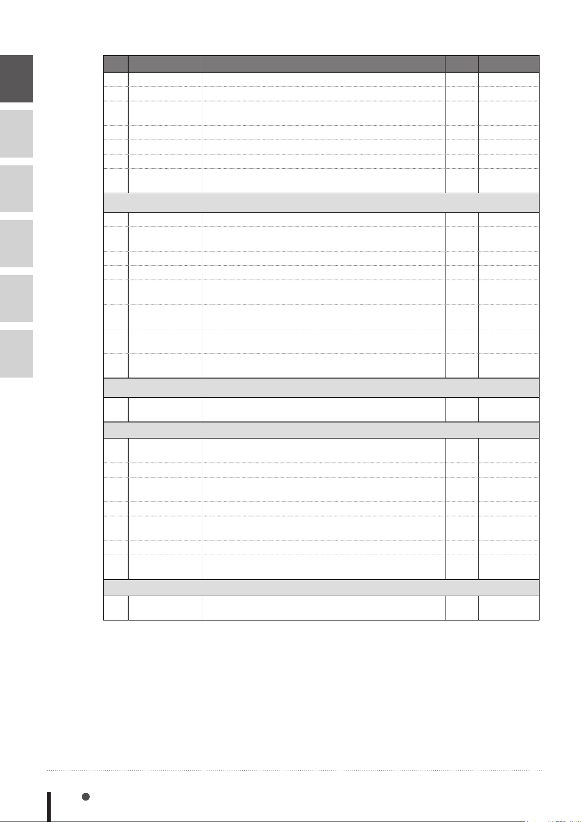
8
9
10
11
12
13
No. Name Description Online Type
121 SPEED
122 SQR Acquires the square root of a specied value.
123 START
124 STR$ Converts a specied value to a character string (↔VAL).
SUB to END SUB
125
126 SUSPEND
127 SWI
Changes the program movement speed of a specied robot.
Species the task number and priority ranking of a specied
program, and starts that program.
Denes a sub-procedure.
Temporarily stops another task which is being executed.
Switches the program being executed, then begins
execution from the rst line.
3
3
3
3
-
-
-
Command
Function
Command
Function
Command
Command
Command
T
128 TAN Acquires the tangent value for a specied value.
129 TCOUNTER
130 TIME$
131 TIMER
132 TO
133 TOLE
134 TORQUE
135 TSKPGM
Outputs count-up values at 1ms intervals starting from the
point when the TCOUNTER variable is reset.
Acquires the current time as an "hh:mm:ss" format character string.
Acquires the current time in seconds, counting from midnight.
Outputs a specied value to the TO port or acquires the TO
status.
Specifies/acquires the tolerance parameter of a specified
robot.
Specifies/acquires the maximum torque command value
which can be set for a specied axis of a specied robot.
Acquires the program number which is registered in a
specied task.
3
3
3
3
3
3
3
3
Function
Function
Function
Function
Command /
Function
Command /
Function
Command /
Function
Function
V
136 VAL
Converts the numeric value of a specied character string
to an actual numeric value. (↔STR$)
W
137 WAIT
138 WAIT ARM
139 WEIGHT
140 WEND Terminates the command block of the WHILE statement.
141 WHERE
WHILE to WEND
142
143 WHRXY
Waits until the conditions of the DI/DO conditional
expression are met (with time-out).
Waits until the axis operation of a specied robot is completed.
Specifies/acquires the tip weight parameter of a specified
robot.
Reads out the current position of the arm of a specified
robot in joint coordinates (pulse).
Controls repeated operations.
Reads out the current position of the arm of a specified
robot as Cartesian coordinates (mm, degrees).
X
144 XYTOJ
Converts the point variable Cartesian coordinate data to the
joint coordinate data of a specied robot. (↔JTOXY).
3
-
-
3
-
3
-
3
3
Function
Command
Command
Command /
Function
Command
Function
Command
Function
Function
8-6 Chapter 8 Robot Language Lists
Page 99
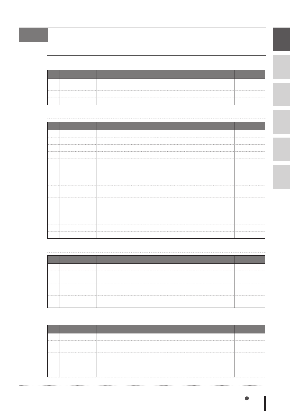
Operation-specific
Program commands
General commands
No. Command Description Online Type
26 DIM
54 LET Executes a specied assignment statement.
96 REM Expresses a comment statement.
Arithmetic commands
Declares the array variable name and the number of
elements.
8
9
-
3
-
Command
Command
Command
10
No. Command Description Online Type
1 ABS Acquires the absolute value of a specied value.
9 ATN Acquires the arctangent of the specied value.
9 ATN2 Acquires the arctangent of the specied X-Y coordinates.
16 COS Acquires the cosine value of a specied value.
23 DEGRAD Converts a specied value to radians (↔RADDEG).
27 DIST Acquires the distance between 2 specied points.
49 INT
57 LSHIFT
95 RADDEG Converts a specied value to degrees. (↔DEGRAD)
103 RSHIFT
115 SIN Acquires the sine value for a specied value.
122 SQR Acquires the square root of a specied value.
128 TAN Acquires the tangent value for a specied value.
Acquires an integer for a specified value by truncating all
decimal fractions.
Shifts a value to the left by the specified bit count.
(↔RSHIFT)
Shifts a value to the right by the specified bit count.
(↔LSHIFT)
3
3
3
3
3
3
3
3
3
3
3
3
3
Function
Function
Function
Function
Function
Function
Function
Function
Function
Function
Function
Function
Function
Date / time
No. Command Description Online Type
20 DATE $ Acquires the date as a "yy/mm/dd" format character string.
129 TCOUNTER
130 TIME $
131 TIMER
Outputs count-up values at 1ms intervals starting from the
point when the TCOUNTER variable is reset.
Acquires the current time as an "hh:mm:ss" format
character string.
Acquires the current time in seconds, counting from
midnight.
3
3
3
3
Function
Function
Function
Function
11
12
13
Character string operation
No. Command Description Online Type
14 CHR $
51 LEFT $
53 LEN
59 MID $
Acquires a character with the specied character code.
Extracts a character string comprising a specied number
of digits from the left end of a specied character string.
Acquires the length (byte count) of a specified character
string.
Extracts a character string of a desired length from a
specied character string.
Operation-specic 8-7
3
3
3
3
Function
Function
Function
Function
Page 100
8
9
No. Command Description Online Type
72 ORD
101 RIGHT $
124 STR $
136 VAL
Acquires the character code of the first character in a
specied character string.
Extracts a character string comprising a specied number
of digits from the right end of a specied character string.
Converts a specied value to a character string (↔VAL).
Converts the numeric value of a specied character string
to an actual numeric value. (↔STR$)
3
3
3
3
Function
Function
Function
Function
10
11
12
13
Point, coordinates, shift coordinates
No. Command Description Online Type
12 CHANGE Switches the hand of a specied robot.
44 HAND Denes the hand of a specied robot.
50 JTOXY
52 LEFTY
56 LOCx
77 PATH Sets the movement path.
85 Pn Denes points within a program.
86 PPNT
102 RIGHTY
117 Sn Denes the shift coordinates within the program.
112 SHIFT
144 XYTOJ
Converts joint coordinate data to Cartesian coordinate data
of a specied robot. (↔XYTOJ)
Sets the hand system of a specied robot to the left-handed
system.
Specifies/acquires point data for a specified axis or shift
data for a specied element.
Creates point data specified by a pallet definition number
and pallet position number.
Sets the hand system of a specified robot to the righthanded system.
Sets the shift coordinate for a specied robot by using the
shift data specied by a shift variable.
Converts the point variable Cartesian coordinate data to the
joint coordinate data of a specied robot.
(↔JTOXY).
3
3
3
3
3
-
3
3
3
3
3
3
Command
Command
Function
Command
Command /
Function
Command
Command
Function
Command
Command
Command
Function
Branching commands
No. Command Description Online Type
35 EXIT FOR Terminates the FOR to NEXT statement loop.
38 FOR to NEXT
GOSUB to
40
RETURN
41 GOTO Unconditionally jumps to the line specied by a label.
47 IF Allows control ow to branch according to conditions.
68 ON to GOSUB
69 ON to GOTO
SELECT CASE
104
to END SELECT
142
WHILE to WEND
Executes the FOR to NEXT statement repeatedly until a
specied value is exceeded.
Jumps to a subroutine with the label specied by GOSUB
statement, and executes that subroutine.
Jumps to a subroutine with labels specified by a GOSUB
statement in accordance with the conditions, and executes
that subroutine.
Jumps to label-specied lines in accordance with the conditions.
Allows control ow to branch according to conditions.
Controls repeated operations.
-
-
-
-
-
-
-
-
-
Command
Command
Command
Command
Command
Command
Command
Command
Command
8-8 Chapter 8 Robot Language Lists
 Loading...