

Page 1

=;76HULHV
&DW1R,((1
352),1(7
86(5¶60$18$/
6&$5$5RERWV
<5&;6HULHV
Page 2

Page 3

CONTENTS
Important information before reading this manual 1
Introduction 1
Safety Precautions (Always read before starting use) 2
Warranty 4
1. Overview of functions 5
2. Controller status transitions 6
3. Input/output assignments 7
4. Part names and functions 9
5. Flow until operation begins 10
PROFINET
User’s Manual
6. Connection 11
6.1 Network structure 11
6.2 Cabling 13
6.3 Noise countermeasures 13
7. GSDles 14
8. Settings 15
8.1 Communication parameter settings 15
9. Monitoring communication data 16
9.1 Using the programming box 16
9.1.1 Switching the port number 17
9.1.2 Input/output list display 18
9.1.3 Input/output details display 18
9.1.4 Switching the output status 19
9.2 Using SCARA-YRCX Studio support software 20
T- 1
Page 4

CONTENTS
10. Disabling an option unit 23
10.1 Making settings 24
10.1.1 Using the programming box 24
10.1.2 Using SCARA-YRCX Studio support software 25
11. Actions to take if communication is not established 27
11.1 Reconsider the startup steps 27
11.2 Viewing the alarm codes in the 7-segment LED 28
11.3 Diagnostics by alarm message 28
11.3.1 Alarms related to network unit connections and settings 28
11.3.2 AlarmsrelatedtoI/Oon/ostatus 29
11.3.3 Alarms that the customer cannot resolve 29
11.3.4 Checking alarm codes in the programming box 30
11.3.5 Checking alarm codes in SCARA-YRCX Studio support software 30
PROFINET
User’s Manual
11.4 Detailed diagnostics using the indicators 31
11.4.1 Common situations and LED illumination patterns 32
12.Specications 33
12.1 Networkspecications 33
12.2 Input/outputspecications 34
13. Reserved word list 35
T- 2
Page 5

Important information before reading this manual
Introduction
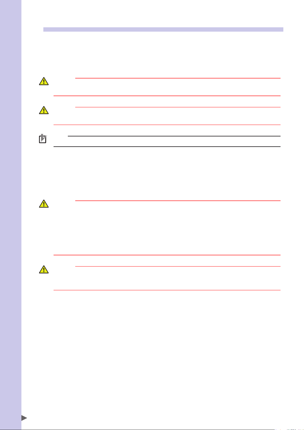
The OMRON network interface unit documentation consists of a User's Manual that is specific to each network
unit that describes the specifications and communication settings of that unit, and a Remote I/O Manual
describing the remote I/O specifications that are common to all network units.
OMRON network interface unit manuals
Content specific to each network unit
(network communication settings, etc.)
(remote I/O and remote command specifications etc.)
Content common to all networks
Important information before reading this manual
PROFINET user’s manual
(this document)
For details on network unit specifications and communication settings, refer to this User's Manual.
For details on communication functions between the controller and the host control device, such as remote I/O
and remote commands, refer to the Remote I/O Manual.
For details on the functions of the robot controller unit, refer to the following manuals.
YRCX Operator’s Manual ..................... for operation of the controller unit
YRCX User’s Manual ............................ for specifications and settings of the controller unit
YRCX Programming Manual ................. for the programming language used by OMRON robot controllers
Remote I/O Manual
1
Page 6
Safety Precautions (Always read before starting use)
Important information before reading this manual
Before using this product, be sure to read this manual carefully as well as the robot controller user's manual
and programming manual. Take sufficient precautions to ensure safety and handle the product correctly.
The cautions given in this manual are related to this product. Refer to the robot controller user's manual for
details on the cautions to be taken with the robot controller system using this product.
The safety precautions are ranked as "WARNING" and "CAUTION" in this manual.
WARNING
FAILURE TO FOLLOW WARNING INSTRUCTIONS COULD RESULT IN SERIOUS INJURY OR DEATH TO THE OPERATOR OR
PERSON SERVICING THE PRODUCT.
CAUTION
Failure to follow CAUTION instructions may result in injury to the operator or person servicing product, or damage
to the product or peripheral equipment.
NOTE
The key points in the operation are explained simply and clearly.
Note that some items described as "CAUTION" may lead to serious results depending on the situation. In any
case, important information that must be observed is explained.
Store this manual where it can be easily referred to, and make sure that it is delivered to the end user.
■Precautions for design
WARNING
• FOR INFORMATION ABOUT THE STATUS OF THE NETWORK SYSTEM AND ROBOT CONTROLLER IN THE EVENT THAT A
COMMUNICATION PROBLEM OCCURS IN THE NETWORK SYSTEM, REFER TO THE MANUAL OF THE HOST CONTROL
DEVICE AS WELL AS TO THIS DOCUMENT. CONFIGURE AN INTERLOCK CIRCUIT IN THE SEQUENCE PROGRAM SO
THAT THE SYSTEM, INCLUDING THE ROBOT CONTROLLER, WILL WORK SAFELY WITH USING THE COMMUNICATION
STATUS INFORMATION.
• THE SAFETY CONNECTOR HAS AN EMERGENCY STOP TERMINAL TO TRIGGER EMERGENCY STOP OF THE ROBOT
CONTROLLER. BY USING THIS TERMINAL, PREPARE A PHYSICAL INTERLOCK CIRCUIT SO THAT THE SYSTEM INCLUDING
THE ROBOT CONTROLLER WILL WORK SAFELY.
CAUTION
The control line and communication cable must not be bound with or placed near the main circuit or power line.
Separate these by at least 100mm. Failure to observe this could lead to communication error or declining
throughput caused by noise.
2
Page 7
■Precautions for installation
WARNING
• ALWAYS CRIMP, PRESS-FIT OR SOLDER THE CONNECTOR WIRING WITH THE MAKER-DESIGNATED TOOL, AND
SECURELY FIX THE CONNECTOR TO THE MODULE.
• ALWAYS SHUT OFF ALL PHASES OF THE POWER SUPPLY EXTERNALLY BEFORE STARTING INSTALLATION OR WIRING
WORK.
FAILURE TO SHUT OFF ALL PHASES COULD LEAD TO ELECTRIC SHOCKS OR PRODUCT DAMAGE.
CAUTION
• Use the robot controller in the environmental conditions specified in this manual. Operation outside the
specified environmental range may cause electric shocks, fire, malfunction or product damage or
deterioration.
• Do not directly touch the conductive portions or electronic components of a network module.
• Never directly touch the controller's interior areas.
• Accurately connect each cable connector to the mounting section.
Failure to observe this could lead to malfunctions caused by a connection fault.
WARNING
ALWAYS SHUT OFF ALL PHASES OF THE POWER SUPPLY EXTERNALLY BEFORE STARTING INSTALLATION OR WIRING
WORK. FAILURE TO SHUT OFF ALL PHASES COULD LEAD TO ELECTRIC SHOCKS OR PRODUCT DAMAGE.
CAUTION
• Make sure that foreign matter, such as cutting chips or wire scraps, does not enter the robot controller.
• Communication cables that contact network modules must be kept inside a duct or secured by clamps. Failure
to place the cable in a duct or secure it by a clamp could damage the cable or module by shifting, movement
or unintentional pulling the cable, or cause malfunction by poor contact condition.
• When disconnecting a connector from the network module, grasp the connector rather than pulling on the
cable. Pulling on the cable could damage the cable and module, possibly causing a poor contact condition
which could result in malfunctions.
Important information before reading this manual
■Precautions for starting and maintenance
WARNING
• DO NOT TOUCH THE TERMINALS WHILE THE POWER IS ON. FAILURE TO OBSERVE THIS COULD LEAD TO
MALFUNCTIONS.
• ALWAYS SHUT OFF ALL PHASES OF THE POWER SUPPLY EXTERNALLY BEFORE PERFORMING CLEANING OR WIRING
WORK. FAILURE TO SHUT OFF ALL PHASES COULD LEAD TO ELECTRIC SHOCKS, PRODUCT DAMAGE OR
MALFUNCTIONS.
• NEVER DISASSEMBLE OR MODIFY ANY OF THE ROBOT CONTROLLER MODULES.
FAILURE TO OBSERVE THIS COULD LEAD TO TROUBLE, MALFUNCTIONS, INJURIES OR FIRES.
CAUTION
Power must be supplied to the robot controller only after supplying power to the host control device. The robot
controller will enter an error state if communication is not established within a certain length of time after the
controller starts.
■Precautions for disposal
CAUTION
Dispose of this product as industrial waste.
3
Page 8

Warranty
Important information before reading this manual
The OMRON robot and/or related product you have purchased are warranted against the defects or
malfunctions as described below.
■Warranty description
If a failure or breakdown occurs due to defects in materials or workmanship in the genuine parts constituting this
OMRON robot and/or related product within the warranty period, then OMRON shall supply free of charge the necessary
replacement/repair parts.
■Warranty period
The warranty period ends 24 months after the date of manufacturing as shown on the products.
■Exceptions to the warranty
This warranty will not apply in the following cases:
1. Fatigue arising due to the passage of time, natural wear and tear occurring during operation (natural fading of painted
or planted surfaces, deterioration of parts subject to wear, etc.)
2. Minor natural phenomena that do not affect the capabilities of the robot and/or related product (noise from computers,
motors, etc.)
3. Programs, point data and other internal data were changed or created by the user.
Failures resulting from the following causes are not covered by warranty.
1. Damage due to earthquakes, storms, floods, thunderbolt, fire or any other natural or man-made disaster.
2. Troubles caused by procedures prohibited in this manual.
3. Modifications to the robot and/or related product not approved by OMRON or OMRON sales representative.
4. Use of any other than genuine parts and specified grease and lubricant.
5. Incorrect or inadequate maintenance and inspection.
6. Repairs by other than authorized dealers.
WARRANTY
OMRON's exclusive warranty is that the products are free from defects in materials and workmanship for a
period of one year (or other period if specified) from date of sale by OMRON.
OMRON MAKES NO WARRANTY OR REPRESENTATION, EXPRESS OR IMPLIED, REGARDING
NONINFRINGEMENT, MERCHANTABILITY, OR FITNESS FOR PARTICULAR PURPOSE OF THE PRODUCTS.
ANY BUYER OR USER ACKNOWLEDGES THAT THE BUYER OR USER ALONE HAS DETERMINED THAT THE
PRODUCTS WILL SUITABLY MEET THE REQUERIMENTS OF THEIR INTENDED USE. OMRON DISCLAIMS ALL
OTHER WARRANTIES, EXPRESS OR IMPLIED.
LIMITATIONS OF LIABILITY
OMRON SHALL NOT BE RESPONSIBLE FOR SPECIAL, INDIRECT OR CONSEQUENTIAL DAMAGES, LOSS OF
PROFITS OR COMERCIAL LOSS IN ANY WAY CONNECTED WITH THE PRODUCTS, WETHER SUCH CLAIM
IS BASED ON CONTRACT, WARRANTY, NEGLIGENCE OR STRICT LIABILITY.
In no event shall the responsibility of OMRON for any act exceed the individual price of the product on
which liability is asserted.
IN NO EVENT SHALL OMRON BE RESPONSIBLE FOR WARRANTY, REPAIR OR OTHER CLAIMS REGARDING
THE PRODUCTS UNLESS OMRON'S ANALYSIS CONFIRMS THAT THE PRODUCTS WERE PROPERLY
HANDLED, STORED, INSTALLED AND MAINTAINED AND NOT SUBJECT TO CONTAMINATION, ABUSE,
MISUSE OR INAPPROPIATE MODIFICATION OR REPAIR.
4
Page 9
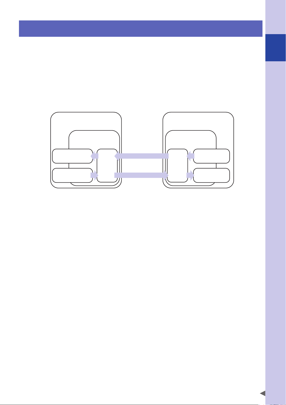
1. Overview of functions
A network interface unit is a device that transmits and receives I/O information via a communication protocol
between a controller and a host control device.
We provide a lineup of products that support fieldbus (DeviceNet, PROFIBUS, etc.) or industrial Ethernet
(EtherNet/IP, PROFINET, etc.).
In any of these networks, the robot controller (slave device) operates in accordance with commands via I/O
control from a host (master device).
While acting as distributed I/O for the host control device, the network interface unit simultaneously shares
I/O information with the controller. The I/O update cycle time between the controller and the network
interface unit is 5 ms.
The I/O update cycle time between the network interface unit and the host control device will vary depending
on the structure of the applicable network.
1
Overview of functions
Host control device
Network unit
(master / I/O controller)
←Status output
Input
m, m+1, ..., m+x
←General-purpose I/O→ ConversionConversion
Output
n, n+1, ..., n+y
Command input→
I/O consists of a general-purpose input/output area, and a dedicated input/output area that has specific
significance such command input and status output that is optimized for control of robot controllers. Using
these, the robot controller can be controlled from the host control device.
The following methods can be used for control via I/O. Combining these methods makes it possible to control
the robot.
(slave / distributed I/O device)
Robot controller
(robot, I/O control)
Network unit
Output
SO, SOW
Input
SI, SIW
1. Controlling the robot controller directly using simple commands and status queries via remote
I/O's dedicated input/output.
Example) Dedicated input: cancel emergency stop, servo on, reset, start program execution, etc.
Dedicated output: CPU_OK, return-to-origin complete, etc.
2. Using remote commands to programlessly control the robot controller directly with advanced
instructions and status queries.
Example) < Transmission >
SIW0 = 0x1031 (absolute reset command for robot no.1)
SIW2 = 0x0015 (axis designation: axis 1 through axis 4)
< Reception >
SOW = 0x0100 (executing command)
SOW = 0x0200 (normal end)
↓
3. Using remote I/O's general-purpose input/output to exchange desired information with an
external peripheral device, and load it into a robot program or sequence program for execution.
Example) WAIT SI(20)=1, 1000 ; Wait until SI(20) turns on; stop command if it does not turn on after 1 second
OUT SO2(), 200 ; SO(27--20) turns on, and turns off after 200 ms
* For details on remote I/O and remote commands, refer to the Remote I/O Manual. For details on robot programs, refer
to the YRCX Programming Manual.
5
Page 10
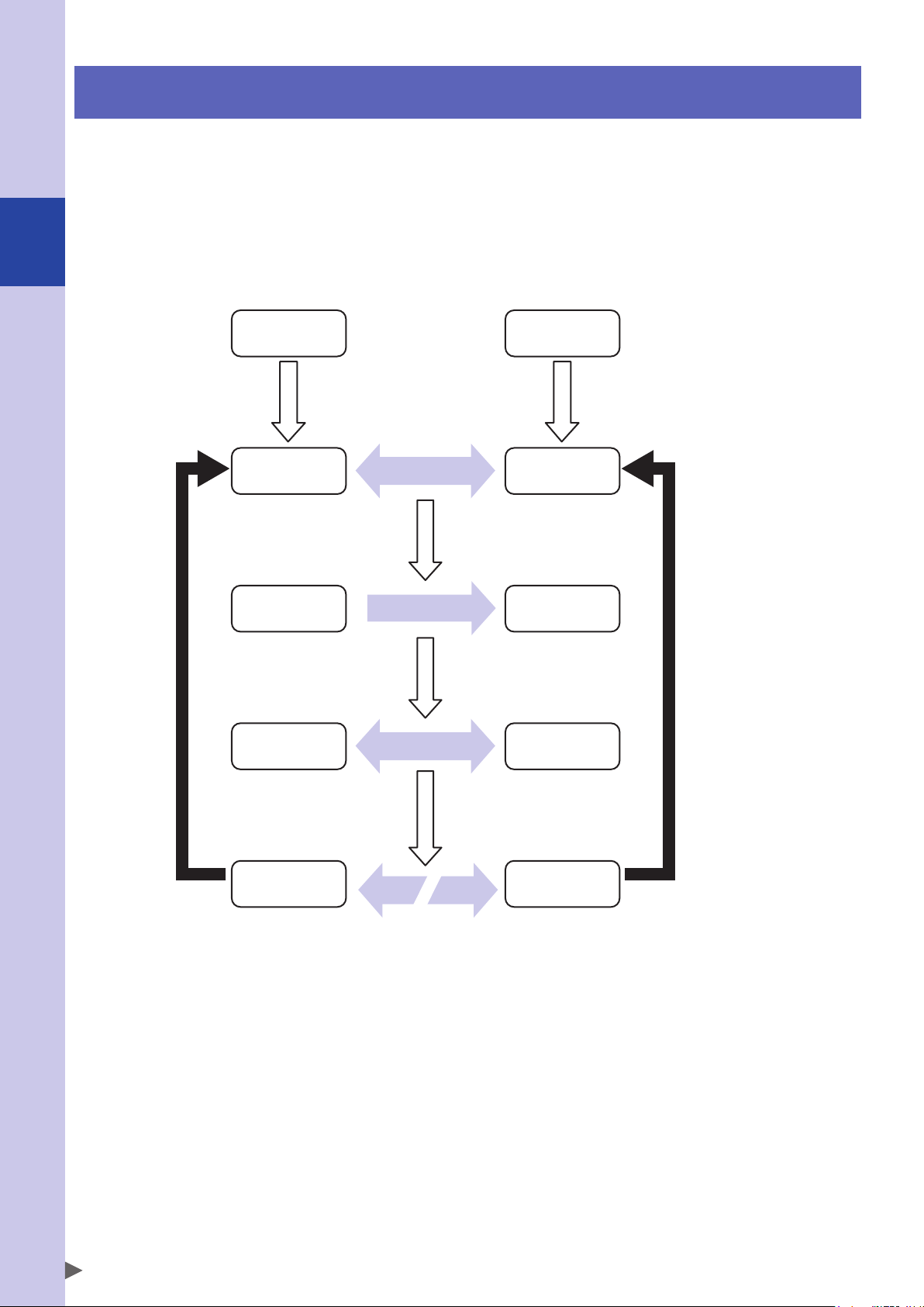
2. Controller status transitions
Power on, controller starts
StartupStartup
Here we explain the status transitions of a robot controller equipped with a network interface unit. A
controller equipped with a network interface unit will initially start up in the emergency stop state. In order
for robot operation to be possible, communication must be established with the host control device, and a
sign that cancels the emergency stop state must be input.
If communication with the host control device is interrupted for any reason, the controller will again transition
to the emergency stop state regardless of the I/O status. In order to resume operation, I/O processing is
2
Controller status transitions
required, such as reestablishing communication, cancelling the emergency stop state, and resetting any error.
Robot controllerHost control device
in emergency stop state
Host control device
Host control device
Host control device
Host control device
Establish communication
Input signals
Exchange I/O information
Robot controller
After both the host control
device and the controller
have started up and
established communication,
cyclic communication begins.
Robot controller
Signals are input to cancel
emergency stop or errors,
putting the robot in an
operable state.
Robot controller
The robot is controlled via
remote commands or
programs
Robot controller
6
Cease communication
When communication
ceases, the robot transitions
to the emergency stop state,
robot power is shut down,
and the program also stops.
Page 11
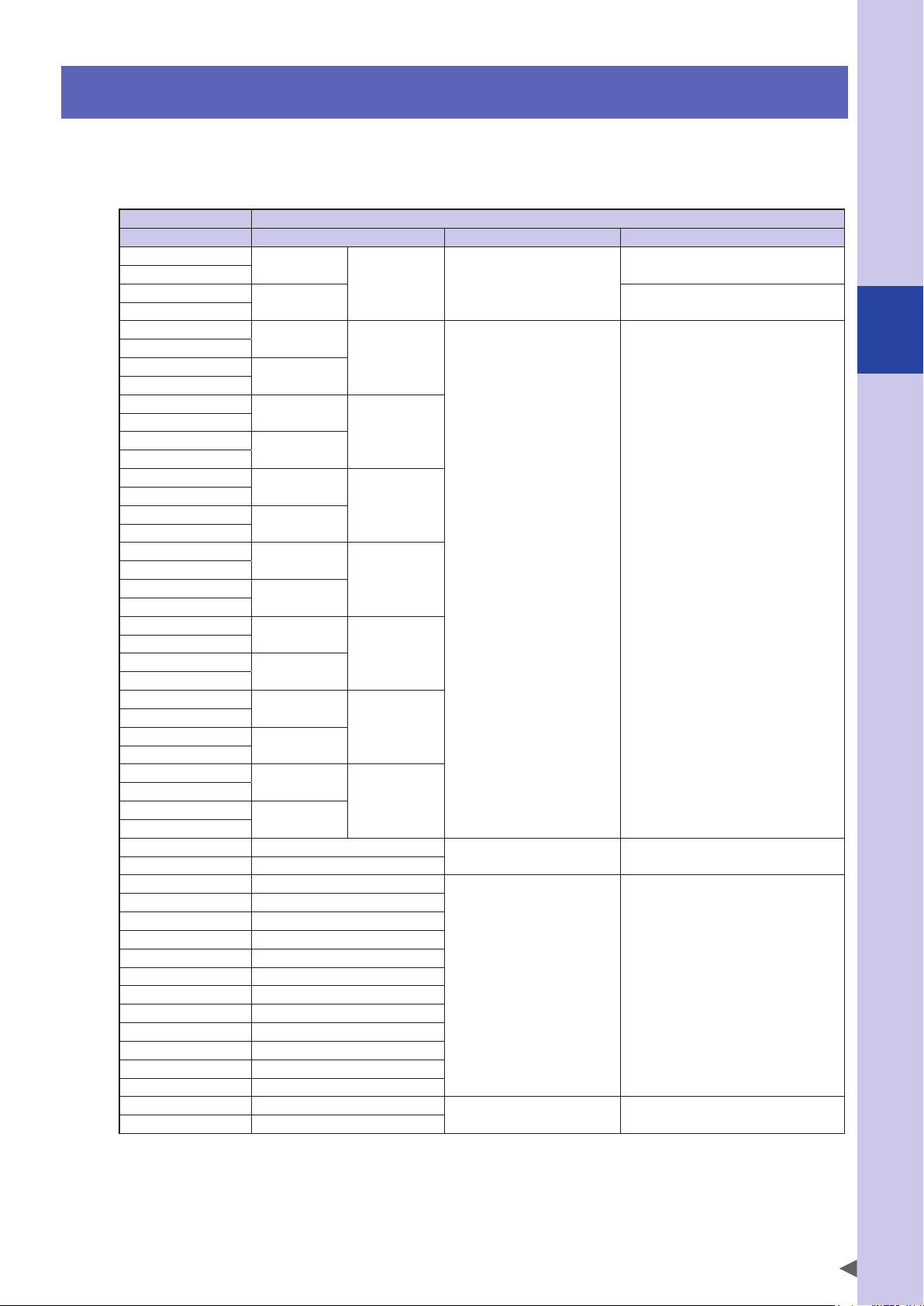
3. Input/output assignments
Here we show the correspondence between the robot controller's serial input/output data and the input/
output data on the network.
■Output from the controller, input to the host device
Host control device Controller
Address (READ) Address (WRITE) Input/output type Use
I (n)
I (n+1)
I (n+2)
I (n+3)
I (n+4)
I (n+5)
I (n+6)
I (n+7)
I (n+8)
I (n+9)
I (n+10)
I (n+11)
I (n+12)
I (n+13)
I (n+14)
I (n+15)
I (n+16)
I (n+17)
I (n+18)
I (n+19)
I (n+20)
I (n+21)
I (n+22)
I (n+23)
I (n+24)
I (n+25)
I (n+26)
I (n+27)
I (n+28)
I (n+29)
I (n+30)
I (n+31)
I (n+32) SO07 - SO00
I (n+33) SO17 - SO10
I (n+34) SO27 - SO20
I (n+35) SO37 - SO30
I (n+36) SO47 - SO40
I (n+37) SO57 - SO50
I (n+38) SO67 - SO60
I (n+39) SO77 - SO70
I (n+40) SO107 - SO100
I (n+41) SO117 - SO110
I (n+42) SO127 - SO120
I (n+43) SO137 - SO130
I (n+44) SO147 - SO140
I (n+45) SO157 - SO150
I (n+46) (Reserve)
I (n+47) (Reserve)
• I(n), I(n+1), ..., (n+47) assume data memory that is divided at each byte (8-bits).
• SOx() is handled as unsigned 8-bit integer data. (x=2-7, 10-17)
• SOW(y) is handled as unsigned 16-bit integer data. (y=0 - 15)
• The upper byte and lower byte of SOW(y) correspond to I(2y+1) and I(2y) respectively.
• SOD(z) is handled as signed 32-bit integer data. (z=2, 4, ..., 14)
• The upper word and lower word of SOD(z) correspond to SIW(z+1) and SIW(n), respectively.
SOW(0)
- Word output
SOW(1) Remote command error code area
SOW(2)
SOD(2)
SOW(3)
SOW(4)
SOD(4)
SOW(5)
SOW(6)
SOD(6)
SOW(7)
SOW(8)
SOD(8)
SOW(9)
SOW(10)
SOD(10)
SOW(11)
SOW(12)
SOD(12)
SOW(13)
SOW(14)
SOD(14)
SOW(15)
Word output /
Double word output
Bit output Status output area
Bit output /
Byte output
Reserved area Use is prohibited
I(n) : Starting address of the input data area for the target controller
Command status area
Command response area /
General-purpose output area
General-purpose output area
3
Input/output assignments
7
Page 12
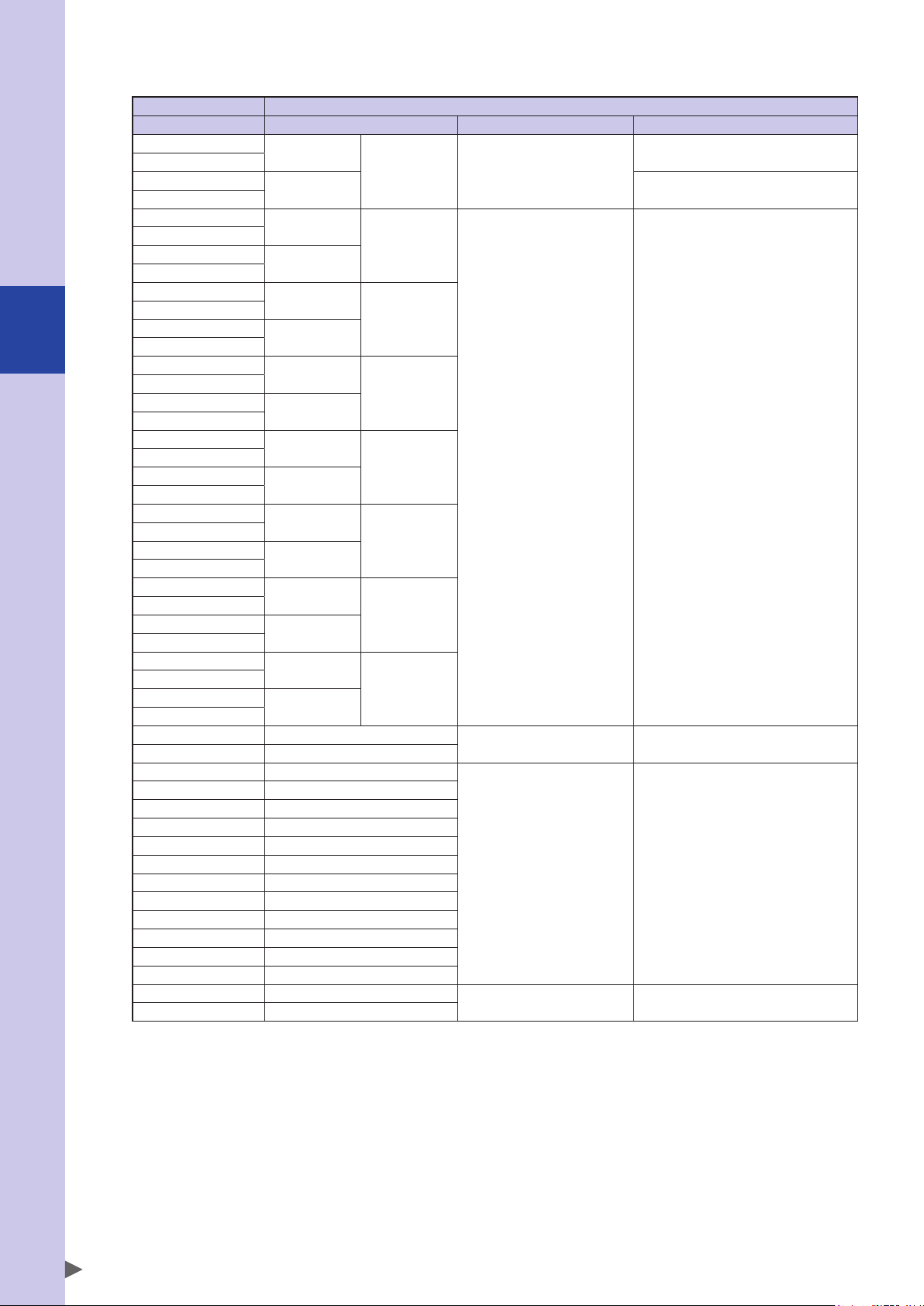
■Output from the host control device, input to the controller
Host control device Controller
Address (WRITE) Address (READ) Input/output type Use
Q m
Q m+1
Q m+2
Q m+3
Q m+4
Q m+5
Q m+6
Q m+7
Q m+8
Q m+9
3
Input/output assignments
Q m+10
Q m+11
Q m+12
Q m+13
Q m+14
Q m+15
Q m+16
Q m+17
Q m+18
Q m+19
Q m+20
Q m+21
Q m+22
Q m+23
Q m+24
Q m+25
Q m+26
Q m+27
Q m+28
Q m+29
Q m+30
Q m+31
Q m+32 SI07 - SI00
Q m+33 SI17 - SI10
Q m+34 SI27 - SI20
Q m+35 SI37 - SI30
Q m+36 SI47 - SI40
Q m+37 SI57 - SI50
Q m+38 SI67 - SI60
Q m+39 SI77 - SI70
Q m+40 SI107 - SI100
Q m+41 SI117 - SI110
Q m+42 SI127 - SI120
Q m+43 SI137 - SI130
Q m+44 SI147 - SI140
Q m+45 SI157 - SI150
Q m+46 (Reserve)
Q m+47 (Reserve)
• Q(m), Q(m+1), ..., Q(m+47) assume data memory that is divided at each byte (8-bits).
• SIx() is handled as unsigned 8-bit integer data. (x=2-7, 10-17)
• SIW(y) is handled as unsigned 16-bit integer data. (y=0 - 15)
• The upper byte and lower byte of SIW(y) correspond to Q(2y+1) and Q(2y) respectively.
• SID(z) is handled as signed 32-bit integer data. (z=2, 4, ..., 14)
• The upper word and lower word of SID(z) correspond to SIW(z+1) and SIW(n), respectively.
SIW(0)
SIW(1) Command data area
SIW(2)
SIW(3)
SIW(4)
SIW(5)
SIW(6)
SIW(7)
SIW(8)
SIW(9)
SIW(10)
SIW(11)
SIW(12)
SIW(13)
SIW(14)
SIW(15)
- Word input
SID(2)
SID(4)
SID(6)
SID(8)
SID(10)
SID(12)
SID(14)
Q(m) : Starting address of the output data area for the target controller
Word input /
Double word input
Bit input Command input area
But input /
Byte input
Reserved area Use is prohibited
Remote command area
Command data area /
General-purpose input area
General-purpose input area
* For details on the functions that are assigned to each serial input/output data, refer to the separate Remote
I/O Manual.
* The reserved area cannot be used.
8
Page 13
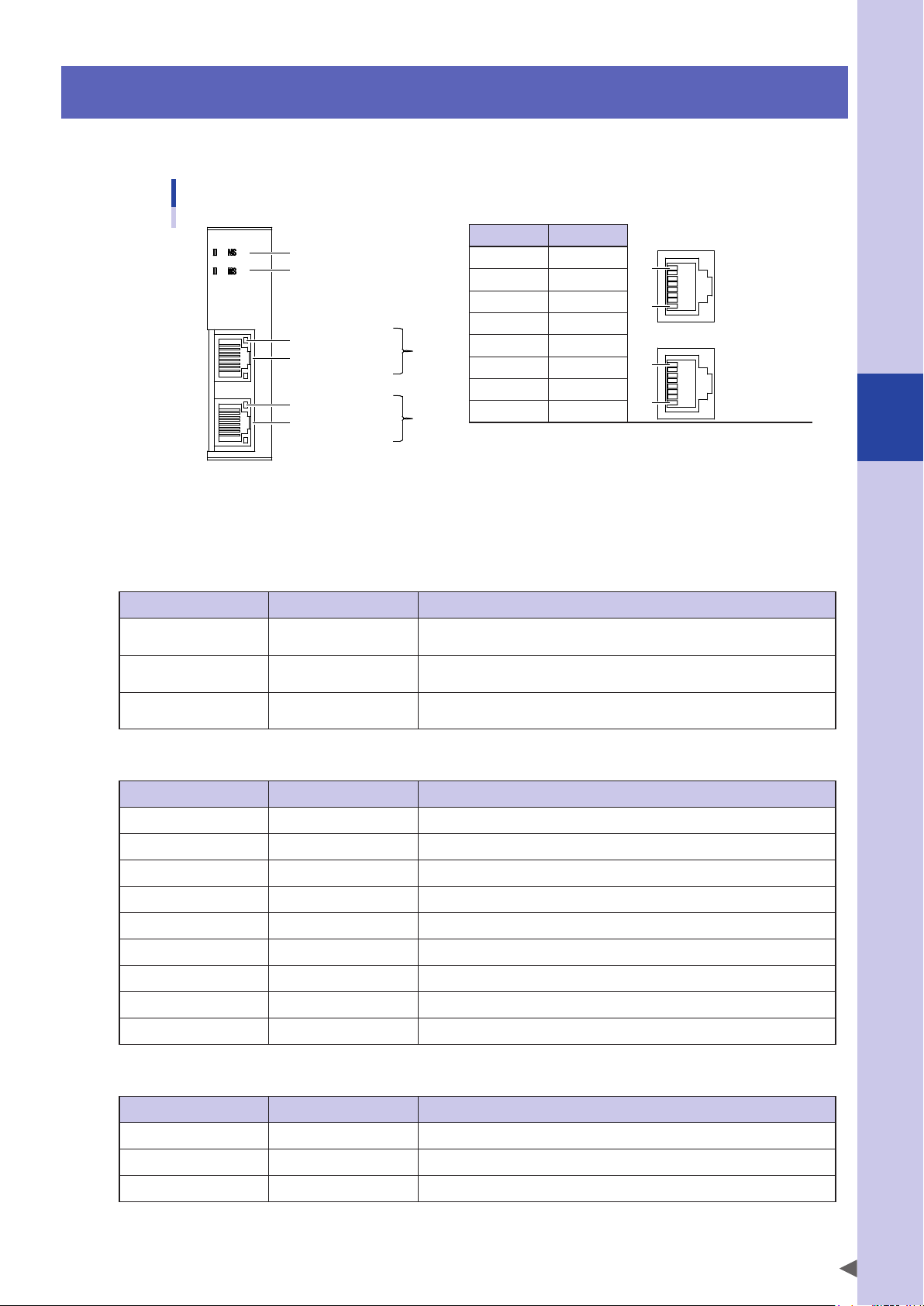
4. Part names and functions
Here we explain the part names and functions of the network interface unit.
Part names
• Pin configuration and connector specifications
Number Name
Network status LED
Module status LED
Link/activity LED
RJ45 modular jack
Link/activity LED
RJ45 modular jack
Port 1
Port 2
1 TXD+
2 TXD-
3 RXD+
4 -
5 -
6 RXD-
7 -
8 -
* An RJ45 modular plug is not included.
8
Port 1
1
8
Port 2
1
4
Connector: RJ45 modular jack
Connect a CAT 5e or higher STP (Shielded Twisted Pair) cable to the connector. From the standpoint of
durability and noise rejection, double-shielded LAN cable for industrial use is recommended.
Network status (NS) LED
LED status Explanation Comment
OFF Offline
Green Online (RUN)
Flashing green Online (STOP)
Power is off
IO controller is not connected
Connection with IO controller is not established
IO controller is in RUN state
Connection with IO controller is not established
IO controller is in STOP state
Module status (MS) LED
LED status Explanation Comment
OFF Not initialized Power is off, or module is in SETUP or "NW_INIT" state
Green Normal operation Module has transitioned from "NW_INIT" state
Flash green once Diagnostic event Diagnostic event is occurring
Flash green at 1 Hz DCP flashing An engineering tool is being used to identify a node on the network
Red Exception error Module is in the "EXCEPTION" state
Part names and functions
Flash red once Setting error Expected ID differs from actual ID
Flash red twice IP address error IP address is not set
Flash red three times Station name error Station name is not set
Flash red four times Internal error A serious error occurred inside the module
Link/activity LED: Port 1 / Port 2
LED status Explanation Comment
OFF No link A link is not established, and communication is not occurring
Green Link detected An Ethernet link is established, but communication is not occurring
Flashing green Activity An Ethernet link is established, and communication is occurring
9
Page 14
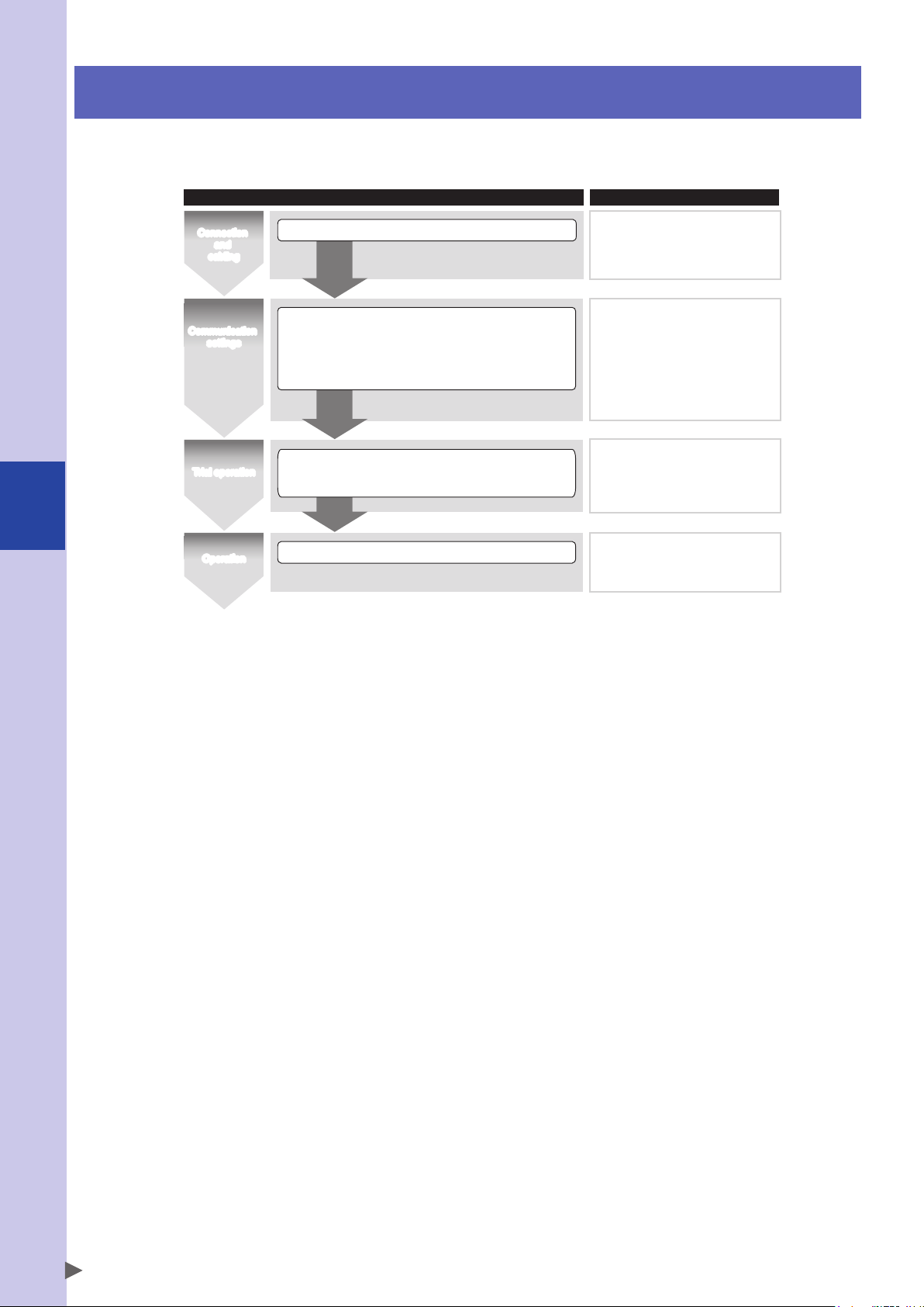
5. Flow until operation begins
Here we explain the flow from startup until operation begins. Proceed with the flow shown in the illustration
below, and consult the appropriate manuals as necessary for each step.
Work steps Refer to:
5
Flow until operation begins
Connection
and
cabling
Communication
Communication
settings
settings
Trial operation
Operation
• Connect connectors and cables
Controller
• No setting items
Host device
• Register the network settings file (GSD)
• Set the communication parameters
• Begin cyclic communication
• Check remote I/O and remote command input/output
• Debug the program
Start operation
6.1 Network structure
6.2 Cabling
6.3 Noise countermeasures
8.1 Communication parameter settings
YRCX user’s manual
Remote I/O Manual
YRCX user’s manual
Remote I/O Manual
10
Page 15

6. Connection
Here we provide an overview of the steps for connecting the robot controller to the network.
Network structure and cable specifications should be designed according to the materials provided by the
network interest group (PI: PROFIBUS & PROFINET International).
6.1 Network structure
PROFINET is an industrial multi-vendor network system based on Ethernet technology that is open and
promoted by PI (PROFIBUS & PROFINET International).
Since it uses standard Ethernet as its lower-level protocol, the network can coexist with general-purpose
Ethernet equipment.
A PROFINET network is typically constructed in a star topology via a switch, but since the robot controller's
PROFINET unit contains a two-port switch, a cable-saving linear network can also be constructed by daisychained connection.
CAUTION
The two Ethernet ports of a PROFINET unit are for the purpose of allowing a versatile network topology within a
single subnet without using a switch. It is not possible for the two ports to be connected to different subnets.
■Example of a cable-saving linear network using daisy-chaining
Host unit
(PROFINET I/O controller)
YRCX
CAUTION
Network equipment such as switches can be used if it satisfies the requirements of the PROFINET network.
However if the equipment is to be used in an environment where noise is a concern, such as a factory, equipment
that meets EMC industrial standards should be selected.
YRCX
Max. 100m
Connection
YRCX
YRCX
6
11
Page 16

■Example of a cable-saving layout that combines PROFINET with a general-purpose Ethernet
network
6
CAUTION
The general-purpose Ethernet ports built into the controller unit do not support the PROFINET communication
protocol. Also, communication settings are made separately from the PROFINET unit.
For details on settings for the general-purpose Ethernet ports, refer to the user's manual of the controller unit.
Host unit
(PROFINET I/O controller)
General-purpose Ethernet port
built into the robot controller
YRCX
General-purpose computer
YRCX YRCX
YRCX
General-purpose Ethernet port
built into the robot controller
Connection
When cabling via option boards as shown above, do not set the option board setting parameter to "disable."
As setting the option board setting parameter to "disable" causes the option board's internal switch to stop
functioning, the general-purpose Ethernet communication pathway to the controller will be shut off.
12
Page 17

6.2 Cabling
WARNING
SHUT OFF THE POWER SUPPLY INPUT TO THE ROBOT CONTROLLER BEFORE PERFORMING THIS WORK.
Insert the LAN cable's modular plug into the controller's modular jack until you hear it click into place.
■Cable specifications
Use LAN cables that meet the following specifications.
Category 5e (CAT 5e) or higher
Shielded Twisted Pair (STP: Shielded Twist Pair)
Double-shielded
100 m or shorter (solid-core cable is recommended if it is over 10 m)
(Example selections) SIEMENS AG
Connector plug IE FC RJ45 Plug 180 6GK1 901-1BB10-2AOO
Cable material IE FC TP standard cable 6XV1 840-2AH10
Tool Stripping tool for IE FC cable 6GK1 901-1GA00
* OO indicates the number of metal housings (A0: 1 / B0: 10 / E0: 50).
* The cable length can be specified in 1-meter units from a minimum of 20 m to a maximum of 1,000 m.
6.3 Noise countermeasures
Although the robot controller unit complies with EMC standards and has a certain amount of resistance to
external noise, there may be cases in which communication is affected by noise depending on the environment
in which the equipment and cable are located.
If communication is affected by noise, a communication error occurs, possibly causing the robot to enter an
emergency stop state, or causing throughput to decline. If there is a source of noise, and this noise is suspected
of affecting communication, please take the following countermeasures.
1. Equipment and cable selection
As the equipment to be connected to the network, select units that conform to EMC directives. Be sure to use cable of the
prescribed specifications.
2. Equipment and cable placement and grounding
If the noise source is nearby, create an appropriate distance between the noise source and the network environment
including the cable. For the robot controller unit and equipment connected to it, be sure to attach an appropriate ground
as directed by the manual of each unit.
3. Adding anti-noise components
Apply the following measures to the robot controller.
• Install a ferrite core on both ends of the cable immediately adjacent to the connector of the device.
• Install a ferrite core or noise filter on the power supply input of the controller.
6
Connection
13
Page 18

7. GSD files
GSD (General Station Description) is a type of network setting file. It contains settings for a device that
supports PROFIBUS or PROFINET.
The network settings file contains information necessary for connecting to a host device, such as I/O size and
communication settings, in a prescribed format. When constructing a network, the settings information of all
connected network devices must be loaded into the host control device.
The appropriate engineering or configuration tool is used to make settings for and write to the host control
device, and during this process it will be necessary to load each device's network settings file into the tool.
The steps for loading the file will depend on the host device used, and on the tool that supports it. Refer to the
manual for the device and tool.
7
GSD files
14
Page 19

8. Settings
Here we explain the parameters that must be set and the settings files that are required in order to begin
communication between the host control device and the robot controller.
8.1 Communication parameter settings
The robot controller does not have parameters related to PROFINET unit communication.
Communication with the host control device (IO controller) requires network parameter settings such as IP
address, subnet mask, and station name.
All of these are set by the corresponding engineering tool (IO Supervisor).
Tasks such as viewing the network parameters and performing "Reset to factory setting" are also all performed
from the engineering tool. For details on how to use the engineering tool, refer to the manual of the device and
software you're using.
■Network settings flow
If there is no topology setting for the host control device (IO controller), such as when the facility is being
started up:
With the robot controller and the engineering tool in a state where they can communicate with each other, specify the
IP address, subnet mask, gateway, and station name individually.
Also make the same settings for the host control device.
If you are replacing only one device within the network, such as when replacing a controller, and topology
settings have been made for the host control device (IO controller):
The network parameters that had been specified for the device before replacement can be automatically assigned by
PROFINET to the replacement device based on the address information of the peripheral device.
This means that in this case, there is no need to make communication settings.
CAUTION
Data of the robot controller other than network parameters is not passed on automatically.
Be sure to back up from the controller before replacing it, download this data to the controller following
replacement, and then connect the controller to the network.
8
Settings
15
Page 20

9
9. Monitoring communication data
On/off data for the host controller device and controller I/O can be monitored via the programming box or
the SCARA-YRCX Studio support software. This can be used to check the input/output addresses during setup
or for debugging.
Monitoring communication data
CAUTION
Since the display update interval of the programming box and of SCARA-YRCX Studio is longer than the data
update interval of I/O information, there may be cases in which accurate information is not shown if the on/off
interval of the I/O information is short.
9.1 Using the programming box
At the initial screen, select [Monitor]-[I/O] to access the monitor screen.
Valid keys and submenu descriptions in the MANUAL mode are shown below.
Valid keys Menu Function
DETAIL Switches between the input/output list and detail displays.
DI Displays the DI monitor.
DO Displays the DO monitor.
MO Displays the MO monitor.
LO Displays the LO monitor.
TO Displays the TO monitor.
SI
SO
SIW Displays the SIW monitor.
SOW Displays the SOW monitor.
NOTE
Four types of I/O data can be transmitted and received via the network: SI, SO, SIW, and SOW.
Displays the SI monitor.
Displays the SO monitor.
Switches the monitor number.
It is possible to change the port number display by switching the monitor number.
For details on the monitor number, refer to "9.1.1 Switching the port number."
16
Page 21

9.1.1 Switching the port number
■Monitor screen
By switching the monitor number the displayed port number can be changed.
The following table shows the correspondence between monitor number and port number.
Port name Monitor number Display range Display format
SI,SO
1
2
3
00-77
100-177
200-277
: ON
: OFF
9
Monitoring communication data
SIW
SOW
* The port name is shown in
shown, DO100-DO177 is shown.
The monitor number is shown in the upper left of the screen.
Press the MONITOR key to switch the monitor number.
1
2
. For example if "DO monitor 2" (monitor number 2 of the DO port) is
0-7
8-15
Monitor number
Monitor number
4-digit hexadecimal
■Monitor Detail screen
By switching the monitor number it is possible to change the tens digit in the order of 0 → 10 → 20. The ones digit can
be changed by using the cursor keys to select [
Changing the ones digit of the port number
For details on operation, refer to "9.1.3 Input/output detail view."
] or [ ] and pressing the enter key.
17
Page 22

9.1.2 Input/output list display
"SI MONITOR 1" screen
"SI MONITOR 1 DETAIL" screen
9
Monitoring communication data
Step1
Step2
At the initial screen, select
[MONITOR] → [I/O].
The "DI Monitor 1" screen then displays.
Select the input/output monitor to
be displayed.
Pressing the F2 key (DI)--F10 key (SOW)
displays the input/output monitor
corresponding to the key.
Pressing the MONITOR key changes the port
number.
Key Input/output
F2 DI
F3 DO
F4 MO
F5 LO
F6 TO
F7 SI
F8 SO
F9 SIW
F10 SOW
Press the [ESC] key to end the monitor
display.
9.1.3 Input/output details display
Step1
Step2
Step3
* There are no displays for SIW and SOW details.
Open the Input/Output Monitor
screen.
Press the [F1] (Details) key.
The "Input/Output Details" screen then
displays.
Changing the port number.
Changing the tens digit of port number
■
Pressing the MONITOR key changes the
tens digit of the port number in the order
of 0 → 10 → 20.
Changing the ones digit of port number
■
Use the cursor key to select [
then press the [enter] key. The port
number can then be changed.
Press the [ESC] key to end the monitor
display.
] or [ ] ,
18
Page 23

9.1.4 Switching the output status
Example of the output monitor detail screen:
In the "Input/output detail view" screen, DO, MO, LO, TO, and SO output can be switched on/off by individual
bits.
CAUTION
Step1
Step2
Step3
• In order to switch the output on/off, the programming box must have control authority.
• SO00-07, SO10-17, and DO00-07 and DO10-17 cannot be changed, since they are dedicated bit outputs that
indicate the status of the controller.
Display the output port "Monitor"
screen.
Press the F3 key (DO)--F6 key (TO) or F8 key
(SO) to display the "Monitor" screen.
Display the "Detail" screen.
Press the F1 key (Detail) to display the
"Detail" screen.
"SO MONITOR1 DETAIL"
Specify the port number.
Changing the tens digit of port number
■
Pressing the MONITOR key changes the
tens digit of the port number in the order
of 0 → 10 → 20.
Changing the ones digit of port number
■
Use the cursor key to select [
then press the [enter] key. The port
number can then be changed.
] or [ ] ,
9
Monitoring communication data
Step4
Switch the output status.
Use the cursor keys to select the ON or OFF
setting for the bit number which changes
the output status, then press the [enter] key
to switch that output status.
Press the [ESC] key to end the monitor
display.
19
Page 24

9
Monitoring communication data
9.2 Using SCARA-YRCX Studio support software
From the window tree, choose [Monitor] and then double-click a port name DI through SOW to monitor. The
monitor screen appears.
The monitor screen contains a list screen and a detail screen. When starting SCARA-YRCX Studio, the monitor
screen that appears first will always be the "Detail screen."
The explanation here uses the example of SI, SO, SIW, and SOW.
Tip
Once you open a monitor screen, it is shown as a tab at the bottom of the screen. The monitor screen can be
displayed by switching tabs.
Tab display
20
Page 25

■SI monitor
Name on/off
Save name Reload name
Name on/off Shows/hides the name.
Save name Sends the name that is entered in the name entry field to the controller.
Reload name Loads the name from the controller, updating the indication of the name entry field.
Check name
I/O name entry field
* For a list of reserved words and system variables, and for usage examples of variable names, refer to "13. Reserved word
list."
Check name
Checks whether the entered I/O name conforms to the prescribed rules. For details on the
naming rules for an I/O name, see "I/O name entry field" below.
Enters the I/O name. Observe the following naming rules when entering the name.
• The maximum is 16 characters.
• Single-byte alphanumeric characters and "_" (underscore) can be used.
• Uppercase and lowercase alphabetical characters are distinguished.
• A numeral cannot be used as the first character.
• It is not possible to assign an I/O name that is identical to a reserved word, or that starts
with a system variable name.
• It is not possible to assign the same I/O name to more than one I/O.
• Since SI00-07 and SI10-17 are dedicated bit inputs, the I/O name cannot be input.
Similarly, I/O name input is not possible for DI inputs (DI00-07 and DI10-17).
I/O name entry field
If the name is hidden
Name on/off
Function
9
Monitoring communication data
■SIW monitor
Display unit
Display unit Displays port values in hexadecimal or decimal.
Function
21
Page 26

9
Monitoring communication data
■SO monitor
Name on/off
Save name Reload name
Name on/off Shows/hides the name.
Save name Sends the name that is entered in the name entry field to the controller.
Reload name Loads the name from the controller, updating the indication of the name entry field.
Check name Checks whether the entered I/O name conforms to the prescribed rules.
ON/OFF button
Name entry field
Check name
ON/OFF button
I/O name entry field
Switches the bit output on/off.
However since SO00-07 and SO10-17 are dedicated bit outputs that indicate the status of the
controller, they cannot be switched on/off. Similarly, DO output (DO00-07 and DO10-17)
cannot be switched on/off.
Enters the I/O name.
However since SO00-07 and SO10-17 are dedicated bit outputs that indicate the status of the
controller, name entry is not possible. Similarly, DO output (DO00-07 and DO10-17) does not
allow name entry.
For details on the rules for I/O names, refer to "I/O name entry field" in the preceding "n SI
monitor (Detail screen)."
If the name is hidden
Name on/off
Function
ON/OFF button
CAUTION
• In order to switch SO or DO on/off, the programming box must release control authority, and the controller must
be in auto mode.
• SO00-07, SO10-17, DO00-07, and DO10-17 are dedicated bit outputs that indicate the status of the controller,
and therefore cannot be changed.
■SOW monitor
Display unit
Function
Display unit Displays port values in hexadecimal or decimal.
Tip
The SOW2-15 output values can be updated to desired values by rewriting the numerical value in the text box
during communication with the controller.
As SOW0 and 1 are dedicated outputs, their values cannot be changed.
As SIW is an external input value, it cannot be changed to an arbitrary value.
22
Page 27

10. Disabling an option unit
If the controller is equipped with a field network option unit, it normally communicates with the host control
device and controls the robot in accordance with the communicated content, so a ladder program is required
for the host device.
When performing teaching or trial operation of the robot by itself in a state in which the host device's ladder
program has not been provided, the robot can be operated without communicating with the host device by
setting the option board to "disabled".
10
CAUTION
When shipped from the factory, all functions of the option unit are set to "enabled." In the "enabled" state, the
robot first becomes operable when an emergency stop or stop signal is input from the host control device.
For details on I/O functionality, refer to the separate "Remote I/O Manual".
Option board setting parameters
Item Values Default value
Slot 1
Option board enabled
CAUTION
The "Option board enable" parameter is set individually for option slots 1 through 4. When changing the settings
of an option board, be sure to verify the location in which the target option board is installed, and change the
setting only for the target slot number.
The illustration below shows the correspondence between the location of each option slot and the actual
installation location.
Slot 2
0 : INVALID, 1 : VALID 1 : VALID
Slot 3
Slot 4
Disabling an option unit
1 2
3 4
YRCX
23
Page 28

10.1 Making settings
An option board can be disabled either from the programming box or from SCARA-YRCX Studio support
software.
10.1.1 Using the programming box
Step1
Open the Parameter Edit screen.
At the initial screen, select [Edit], press [Enter], then select [Parameter].
10
Disabling an option unit
Step2
Press the [F6] (OPTION) key to display the Option Parameters screen.
Step3
Select the desired parameter.
Use the cursor up/down keys to select the parameter to be edited, then press the [F1] (EDIT) key.
24
Page 29

Step4
NOTE
Edit the parameter.
Change the setting for the target slot, and press the enter key.
1 2
10
3 4
Disabling an option unit
YRCX
The values of the option board enable parameter correspond to slots 1 through 4 starting from the left.
Verify the slot in which the network unit is installed, and change the value only for the target slot number.
Step5
Press the [ESC] key to end the editing operation.
The specified content is applied after the controller is restarted.
10.1.2 Using SCARA-YRCX Studio support software
Step1
In the window tree, select the board parameters.
In the window tree, select [Parameter]-[Option], and double-click [Board Enable].
* C101-C104 correspond to slots 1--4.
Verify the slot in which the network unit is installed, and change the value only for the target slot
number.
25
Page 30

Step2
Select the option slot "Value" column, and choose either "VALID" or "INVALID."
C101 through C104 in the chart correspond to option slots 1 through 4 of controller 1.
If controllers are linked to each other in a YC-Link/E network, the option slots of controller 2 and following
are shown in C201 through C204.
10
Disabling an option unit
Option slots 1 through 4 Choose "VALID" or "INVALID"
Tip
Step3
If a cell's value is changed, its background color turns red.
Click the [Save] button to save the settings.
When saving is complete, the cell color changes from red to white.
The specified content is applied after the controller is restarted.
[Save] button
26
Page 31

11. Actions to take if communication is not established
Network unit7-segment LED
If communication is not established, diagnose the situation by referring to the alarm codes or alarm messages
of the controller unit and to the network unit's LED illumination pattern, and take the appropriate actions.
11
Actions to take if communication is not established
YRCX
11.1 Reconsider the startup steps
The following steps must be taken when starting up the network system.
If communication cannot be established after the cabling and settings have been completed, it is possible that
one of the steps was not performed correctly.
■Procedure
• Connections
Determine the network configuration
Connect cables
Noise countermeasures (only if necessary)
• Settings
Settings for the host control device (PROFINET IO controller)
Use GSD file to register device information
Network parameter settings for the robot controller
(station name, IP address, etc.)
→After settings, put the system in the RUN state
Settings on the robot controller (PROFINET IO device)
No items to set
Communication is established, and cyclic communication begins
If communication is not established, check the following points.
• Connections: Do the cables meet the network specifications, and are they securely connected?
• Parameter settings: Are parameters such as station name and IP address specified from the host control device
(IO controller)?
Is the topology specified?
• GSD file: Is the correct GSD file registered on the host control device (IO controller)?
27
Page 32

11
SOE
Actions to take if communication is not established
11.2 Viewing the alarm codes in the 7-segment LED
Normal state
• The "PWR" LED on the front of the controller is lit, and the 7-segment LED shows the following.
(Servo off, return-to-origin incomplete, emergency stop cancelled)
Abnormal state
• The "PWR" LED on the front of the controller is lit, and the 7-segment LED shows an alarm code.
• Note the alarm message on the programming box, and take the actions prescribed by the troubleshooting guidelines.
(Example) Display when an alarm occurs
"E + alarm group number" and "alarm type number" are displayed alternately.
* In the example above, alarm code "17.403" is indicated.
* For details on the alarm messages and content corresponding to each alarm code, refer to "11.3 Diagnostics by alarm
message," or the troubleshooting section of the YRCX controller user's manual.
11.3 Diagnostics by alarm message
Alarm messages related to the network unit are shown below.
Alarm messages not listed in this document may be alarms resulting from the robot controller unit.
Refer to the troubleshooting section of the robot controller user's manual.
11.3.1 Alarms related to network unit connections and settings
These errors occur if communication is not established, or if communication is unstable.
12.571 : PROFINET link error
Code : &H000C &H023B
a. There is a problem in the network cable.
Meaning/Cause
Action
12.572 : PROFINET overtime error
Code : &H000C &H023C
Meaning/Cause
Action
b. The communication settings of the network system are incorrect.
c. The host control device is not powered-on, or is stopped, or has malfunctioned.
d. The network unit has malfunctioned.
1. Check whether network cables might be broken, unconnected, mis-wired, or out-of-spec
(cable length, etc.).
2. Check the communication settings.
3. Check whether the host control device is operating correctly.
4. Replace the network unit.
a. A communication problem is occurring because of noise etc. on the network system.
b. The power supply of the host control device is shut off or stopped.
1. Apply noise countermeasures to the network system cables and controller.
2. Check whether the host control device is operating normally.
3. Check the network system cable connections.
28
Page 33

11.3.2 Alarms related to I/O on/off status
These errors occur depending on the state of the dedicated input/output.
If the robot controller is equipped with a network unit, the robot cannot be operated unless an emergency stop
or STOP signal is input from the host device, even if the robot is being controlled from somewhere other than
the host control device.
For details on I/O functions, refer to "Remote I/O Manual."
12.400 : Stop input on
Code : &H000C &H0190
Meaning/Cause
Action
a. Program execution or axis movement was attempted in the stop status.
b. Robot was put in the stop status during program running or axis movement.
1. Establish communication with the host control device, and put the unit in SIO6=1 status
(cancel stop).
12.600 : Emergency stop on
Code : &H000C &H0258
a. Communication with the host control device is not established.
b. Although communication with the host control device is established, SI00 (emergency
stop input) is not on.
Meaning/Cause
Action
c. The emergency stop terminal of the SAFETY connector is open, or the connector is not
connected.
d. The emergency stop button of the programming box is pressed, or a terminator is not
connected to the PB connector.
1. Establish communication with the host control device, and set SI00=1 (cancel emergency
stop).
2. Close the emergency stop terminals on SAFETY connector.
3.
Cancel the emergency stop button of the programming box, or connect a terminator
instead.
11.3.3 Alarms that the customer cannot resolve
These are error messages that are not expected to occur in the field.
If one of these errors occurs, please contact your distributor with details of the situation.
11
Actions to take if communication is not established
12.765 : PROFINET initialize error
Code : &H000C &H02FD
Meaning/Cause
Action
Failed to initialize the network unit.
Contact your distributor with details on this problem.
12.900 : Incorrect option setting
Code : &H000C &H0384
a. The ID setting on the option module is not correct.
Meaning/Cause
Action
b. Option modules that cannot be mixed were installed.
c. Unidentified option modules were installed.
Contact your distributor with details on this problem.
12.904 : SIO option board initialize error
Code : &H000C &H0338
Meaning/Cause
Action
Failed to initialize SIO option board.
Contact your distributor with details on this problem.
29
Page 34

11.3.4 Checking alarm codes in the programming box
11
Actions to take if communication is not established
Step1
Step2
Open the Parameter Edit screen.
At the initial screen, select [Edit], press [Enter], then select [Parameter].
Check the alarm code that is occurring.
Press the F1 key (RELOAD) to update the display to the current state.
In the illustration, alarm code 10.900 is occurring.
11.3.5 Checking alarm codes in SCARA-YRCX Studio support software
Alarm codes and alarm messages are shown in the "Controller Monitor" located in the lower left of the screen.
30
Page 35

11.4 Detailed diagnostics using the indicators
Illumination patterns
Details of the situation can be obtained from the illumination pattern of the network unit indicators.
■Network unit indicators and illumination patterns
Part names
Network status LED green (single color) LED
Module status LED green/red (two-color) LED
Link/activity LED
Port 1
green (single color) LEDs
Link/activity LED
Port 2
Network status (NS) LED
LED status Explanation Comment
OFF Offline
Green Online (RUN)
Flashing green Online (STOP)
Power is off
IO controller is not connected
Connection with IO controller is not established
IO controller is in RUN state
Connection with IO controller is not established
IO controller is in STOP state
lit green
flashing green
lit red
flashing red
unlit
11
Actions to take if communication is not established
Module status (MS) LED
LED status Explanation Comment
OFF Not initialized Power is off, or module is in SETUP or "NW_INIT" state
Green Normal operation Module has transitioned from "NW_INIT" state
Flash green once Diagnostic event Diagnostic event is occurring
Flash green at 1 Hz DCP flashing An engineering tool is being used to identify a node on the network
Red Exception error Module is in the "EXCEPTION" state
Flash red once Setting error Expected ID differs from actual ID
Flash red twice IP address error IP address is not set
Flash red three times Station name error Station name is not set
Flash red four times Internal error A serious error is occurring inside the module
Link/activity LED: Port 1 / Port 2
LED status Explanation Comment
OFF No link A link is not established, and communication is not occurring
Green Link detected An Ethernet link is established, but communication is not occurring
Flashing green Activity An Ethernet link is established, and communication is occurring
31
Page 36

11.4.1 Common situations and LED illumination patterns
■Illumination patterns when connection exists
1. PROFINET IO controller in RUN state, I/O control possible
11
Actions to take if communication is not established
Network Status
Module Status
Link/Activity
■Presumed state
Connection with the host control device (IO controller) is
established, and I/O control via cyclic communication is
possible.
■Action to take
None. Settings have completed normally, and communication
has begun.
2. PROFINET IO controller in idling state, I/O control not possible
Network Status
Module Status
Link/Activity
■Presumed state
Connection with the host control device (IO controller) is
established, but cyclic communication has not begun.
■Action to take
Use the host control device to switch the control mode to
START.
■Illumination patterns when connection does not exist
3. Unset parameters
Network Status
Module Status
Link/Activity
MS flashing red twice: IP address is not set.
MS flashing red three times:
■Presumed state
Parameters such as the IP address or station name have not
been set from the IO supervisor (e.g., engineering tool for the
host control device).
Network topology has not been specified, and neighbor
detection via LLDP is not functioning.
Station name is not set.
4. LAN cable unconnected
Network Status
Module Status
Link/Activity
5. Option invalid setting
Network Status
Module Status
Link/Activity
■Action to take
From the IO supervisor, manually specify the IP address and
station name.
Make topology settings for the IO controller.
■Presumed state
The cable between the host control device and robot controller
is unconnected.
■Action to take
Check the cabling. Check the connection state of the peripheral
devices.
■Presumed state
The option board setting parameter is set to "invalid."
Alternatively, the controller power is shut off.
■Action to take
Set the option board setting parameter to "valid," and restart
the robot controller. Alternatively, check the power supply
input to the controller.
32
Page 37

12. Specifications
12.1 Network specifications
Spec. Item Contents
YRCX : V1.21 or later
Supported software versions
Network specification
conformance
Conformance class Conformance Class B / IO Device
Product revision 1.00
GSD file name GSDML-V2.3-YMC-RCX3-20150203.xml
Transmission speed 100Mbps (Auto-negotiation)
Connector specifications RJ-45 connector (8-pole modular connector) 2 ports
Conforming cable specifications CAT 5e or higher STP cable (double shield)
Max. cable length 100m
Monitor LEDs Module Status(MS), Network Status(NS), Link/Activity:Port1-2
PBEX : V1.08 or later
SCARA-YRCX Studio : V1.0.1 or later
PROFINET IO V2.2
Dedicated word input 2 words (4 bytes)
General-purpose word input 14 words (28 bytes)
Input : 48bytes
Dedicated bit input 16 bits (2 bytes)
General-purpose bit input 96 bits (12 bytes)
12
Specifications
Input/output data size
Output : 48bytes
Reserved area 2 bytes
Dedicated word output 2 words (4 bytes)
General-purpose word output 14 words (28 bytes)
Dedicated bit output 16 bits (2 bytes)
General-purpose bit output 96 bits (12 bytes)
Reserved area 2 bytes
33
Page 38

12
Specifications
12.2 Input/output specifications
Controller ⇒ Host control device Host control device ⇒ Controller
Address (WRITE) I/O function Address (READ) I/O function
SOW(0)
SOW(1) Command response area SIW(1) Command data area
SOW(2)
SOW(3) SIW(3)
SOW(4)
SOW(5) SIW(5)
SOW(6)
SOW(7) SIW(7)
SOW(8)
SOW(9) SIW(9)
SOW(10)
SOW(11) SIW(11)
SOW(12)
SOW(13) SIW(13)
SOW(14)
SOW(15) SIW(15)
SO07 - SO00
SO17 - SO10
SO27 - SO20
SO37 - SO30 SI37 - SI30
SO47 - SO40 SI47 - SI40
SO57 - SO50 SI57 - SI50
SO67 - SO60 SI67 - SI60
SO77 - SO70 SI77 - SI70
SO107 - SO100 SI107 - SI100
SO117 - SO110 SI117 - SI110
SO127 - SO120 SI127 - SI120
SO137 - SO130 SI137 - SI130
SO147 - SO140 SI147 - SI140
SO157 - SO150 SI157 - SI150
(Reserve)
(Reserve) (Reserve)
-
SOD(2)
SOD(4)
SOD(6)
SOD(8)
SOD(10)
SOD(12)
SOD(14)
SO00
SO01 CPU_OK status output SI01 Servo on input
SO02 Servo on status output SI02
SO03 Alarm status output SI03
SO04 MPRDY status output SI04
SO05
SO06 SI06 Stop input
SO07 SI07 Reserved area (do not use)
SO10 Auto mode status output
SO11
SO12
SO13
SO14 Program reset status output SI14
SO15 Warning output SI15 Program reset input
SO16
SO17 SI17
Command status area SIW(0)
SIW(2)
SIW(4)
SIW(6)
Command response area /
General-purpose output area
Emergency stop status
output
Reserved area (do not use)
Return-to-origin complete
status output
Sequence program execution
status output
Robot program operating
output
Reserved area (do not use)
General-purpose output area
Reserved area (do not use)
SIW(8)
SIW(10)
SIW(12)
SIW(14)
SI07 - SI00
SI17 - SI10
SI27 - SI20
(Reserve)
-
SID(2)
SID(4)
SID(6)
SID(8)
SID(10)
SID(12)
SID(14)
SI00 Emergency stop input
SI05
SI10 Sequence control input
SI11 Reserved area (do not use)
SI12 Automatic operation start
SI13 Reserved area (do not use)
SI16 Alarm reset input
Remote command area
Command data area /
General-purpose input area
Reserved area (do not use)
Return-to-origin input
(incremental type axis)
Return-to-origin input
(absolute type axis)
General-purpose input area
Reserved area (do not use)
For details on each I/O function, refer to the separate "Remote I/O Manual".
34
Page 39

13. Reserved word list
Because the following names are reserved for the robot language, they cannot be used as I/O names.
A
ABS
ABSADJ
ABSRPOS
ACC
ACCEL
ACCESS
ACO
ALL
ALM
ALMRST
AND
ARCHP1
ARCHP2
ARM
ARMCND
ARMSEL
ARMTYP
ARP
ARY
ASPEED
ATN
ATN2
ATTR
AXWGHT
B
BIN
BREAK
C
CALL
CASE
CFG
CHANGE
CHGPRI
CHR
CLOSE
CMU
CNT
CONT
COPY
COS
CURTQST
CURTRQ
CUT
D
DATE
DBP
DEC
DECEL
DEF
DEGRAD
DELAY
DI
DIM
DIR
DIST
DO
DPM
DRIVE
DRIVEI
DRV
DS
DSPEED
E
ELSE
ELSEIF
EMG
END
ENDIF
EOF
EQV
ERA
ERL
ERR
ERROR
ETH
ETHSTS
EXIT
EXITTASK
F
FN
FOR
FREE
G
GEP
GEPSTS
GO
GOSUB
GOTO
H
HALT
HALTALL
HAND
HEX
HND
HOLD
HOLDALL
I
IDIST
IF
IMP
INCH
INCHT
INCHXY
INIT
INPUT
INT
ION
J
JL
JOG
JOGT
JOGXY
JTOXY
L
LEFT
LEFTY
LEN
LET
LINEMODE
LOAD
LOC1
LOC2
LOC3
LOC4
LOC5
LOC6
LOCF
LOG
LSHIFT
M
MAINPG
MCHREF
MEM
MID
MNS
MOD
MODE
MOTOR
MOVE
MOVEI
MOVET
MRF
MRKSET
MSG
MSGCLR
MSPEED
N
NAME
NEXT
NOT
O
OFF
OFFLINE
ON
ONLINE
OPEN
OPT
OR
ORD
ORGORD
ORGRTN
ORIGIN
OUT
OUTPOS
P
P
PATH
PC
PCM
PDEF
PGM
PGMTSK
PGN
PLS
PLT
PMOVE
PNM
PNT
PPNT
PRINT
PRM
PSHFRC
PSHJGSP
PSHMTD
PSHRSLT
PSHSPD
PSHTIME
PUSH
PWR
R
RADDEG
RBT
READ
REF
REM
13
Reserved word list
35
Page 40

13
REN
RESET
RESTART
RESUME
RETURN
RIGHT
RIGHTY
RSHIFT
RUN
RUNTO
S
S
SCK
SELECT
SEND
SEQCMPL
SEQUENCE
SERVO
SET
SETGEP
SETPW
SFT
SGI
SGR
SHARED
SHIFT
SI
SID
SIN
SIW
SKIP
SKIPTO
SO
SOD
SOW
SPEED
SQR
START
STEP
STOP
STOPON
STR
SUB
SUSPEND
SWI
SYNCHK
T
TAG
TAN
TASKS
TCHXY
TCOUNTER
TEACH
THEN
TIM
TIME
TIMER
TO
TOLE
TORQUE
TSKECD
TSKMON
TSKPGM
V
VAL
VAR
VEL
VER
W
WAIT
WEIGHT
WEND
WHERE
WHILE
WHRXY
WHRXYEX
WRITE
X
XOR
XY
XYTOJ
Y
YZ
Z
ZX
Reserved word list
■List of system variables
Because the following names are used as system variable names, they cannot be used at the beginning of other
variable names (n: numeric value).
A
Acn
D
DIn
DINMn Hn PNn TOn
DOn
DONMn LOn SIn
F M
FN MOn Sn
G P
GPn PCn SONMn
H
L S
Pn
SINMn
Son
T
■Variable name usage examples
• Although keywords which are reserved as robot language words cannot be used as they are, they can be used as
variable names if alphanumeric characters are added to them.
Example: "ABS" cannot be used, but "ABS1" or "ABSX" can be used.
• Keywords reserved as system variables cannot be used at the beginning of other variable names, even if alphanumeric
characters are added to them.
36
Example: "FN" cannot be used. "FNA" and "FN123" also cannot be used.
Page 41

Page 42

Revision history
A manual revision code appears as a suffix to the catalog number on the front cover manual.
Cat. No. I247E-EN-01
Revision code
The following table outlines the changes made to the manual during each revision.
Revision code
01 July 2016 Original production
Date Description
Page 43

Page 44

&DW1R,((1
$XWKRUL]HG'LVWULEXWRU
3ULQWHGLQ(XURSH
 Loading...