


Switch Mode Power Supply S8VS 1
Switch Mode Power Supply
S8VS (15/30/60/90/120/180/240-W Models)
15/30-W Models
Compact, Thin Power Supplies That Mount
Just About Anywhere to Contribute to
Control Panel Downsizing
• Compact, thin size: 22.5 × 85 × 96.5 mm (W × H × D).
• Three mounting directions
(standard, horizontal, facing horizontal).
• Mounting directly onto the panel is possible.
• Safety standards:
UL508/60950-1/1604, CSA C22.2 No. 14/60950-1/213,
EN50178 (= VDE0160), EN60950-1 (= VDE0805).
60/90/120/180/240-W Models
New Models with Total Run Time Monitor in
Addition to Models with Maintenance
Forecast Monitor
• Compact size: 40 × 95 mm (W × H) (60-W Models).
• Status displayed on 3-digit, 7-segment display.
• Safety standards:
UL508/60950, CSA C22.2 No. 14/60950,
EN50178 (= VDE0160), EN60950 (= VDE0805).
Features Common to All Models
• Mount to DIN Rail.
• Lead-free solder.
2 Switch Mode Power Supply S8VS
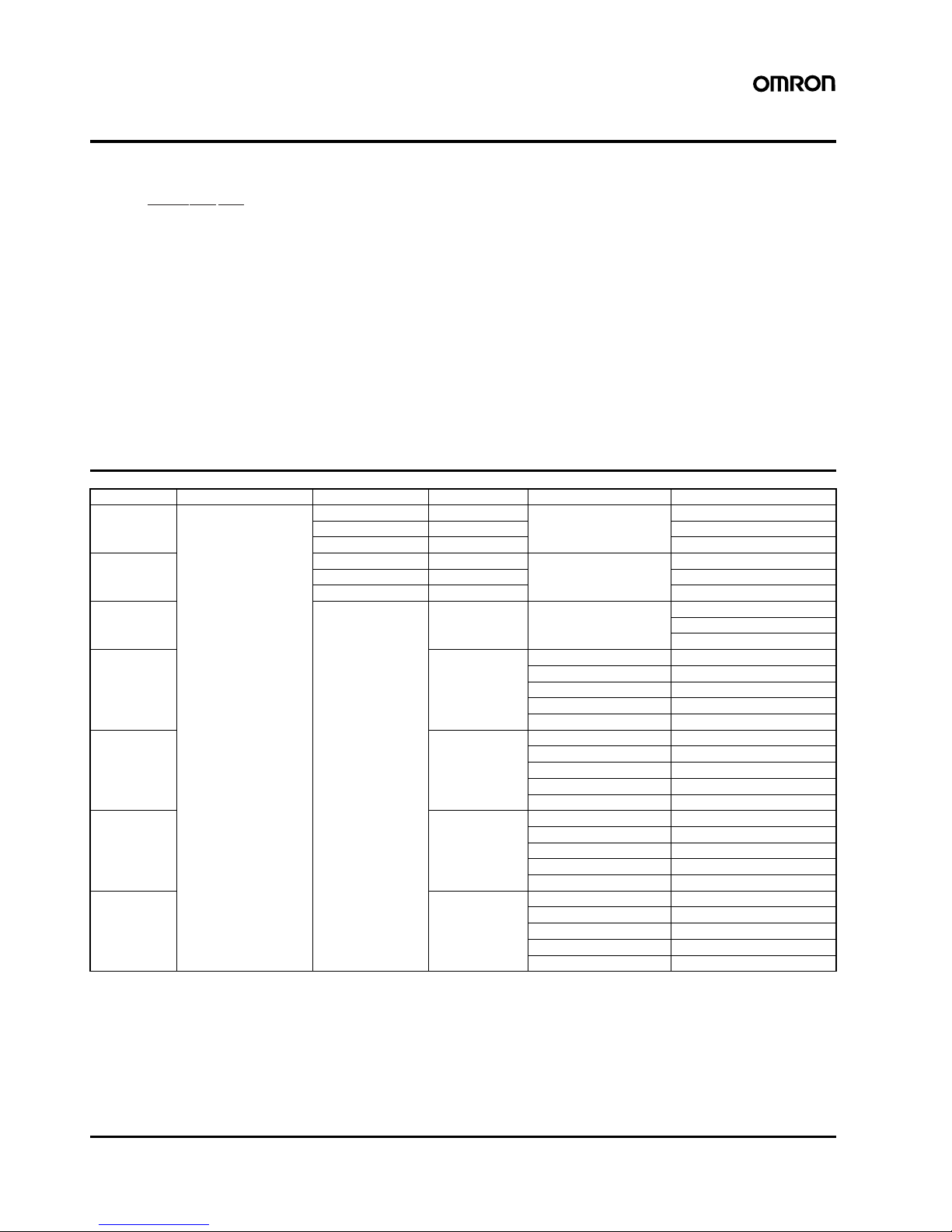
Model Number Structure
■ Model Number Legend
Ordering Information
Note: 1. The output capacity of the S8VS-01505 is 10 W.
2. The output capacity of the S8VS-03005 is 20 W.
12
3
S8VS- @@@@@@@
1. Power Ratings
015: 15 W
030: 30 W
060: 60 W
090: 90 W
120: 120 W
180: 180 W
240: 240 W
2. Output voltage
05: 5 V
12: 12 V
24: 24 V
3. Configuration
15-W, 30-W Models
None: Standard
60-W Models
None: Standard
A: With maintenance forecast monitor
B: With total run time monitor
90-W, 120-W, 180-W, 240-W Models
None: Standard
A: With maintenance forecast monitor
and undervoltage alarm
(transistor (sinking))
B: With total run time monitor and un-
dervoltage alarm
(transistor (sinking))
AP: With maintenance forecast monitor
and undervoltage alarm
(transistor (sourcing))
BP: With total run time monitor and un-
dervoltage alarm
(transistor (sourcing))
Power ratings Input Voltage Output voltage Output current Alarm output Model number
15 W 100 to 240 VAC 5 V 2.0 A --- S8VS-01505 (See note 1.)
12 V 1.2 A S8VS-01512
24 V 0.65 A S8VS-01524
30 W 5 V 4.0 A --- S8VS-03005 (See note 2.)
12 V 2.5 A S8VS-03012
24 V 1.3 A S8VS-03024
60 W 24 V 2.5 A --- S8VS-06024
S8VS-06024A
S8VS-06024B
90 W 3.75 A --- S8VS-09024
Sinking S8VS-09024A
Sourcing S8VS-09024AP
Sinking S8VS-09024B
Sourcing S8VS-09024BP
120 W 5 A --- S8VS-12024
Sinking S8VS-12024A
Sourcing S8VS-12024AP
Sinking S8VS-12024B
Sourcing S8VS-12024BP
180 W 7.5 A --- S8VS-18024
Sinking S8VS-18024A
Sourcing S8VS-18024AP
Sinking S8VS-18024B
Sourcing S8VS-18024BP
240 W 10 A --- S8VS-24024
Sinking S8VS-24024A
Sourcing S8VS-24024AP
Sinking S8VS-24024B
Sourcing S8VS-24024BP
Switch Mode Power Supply S8VS 3
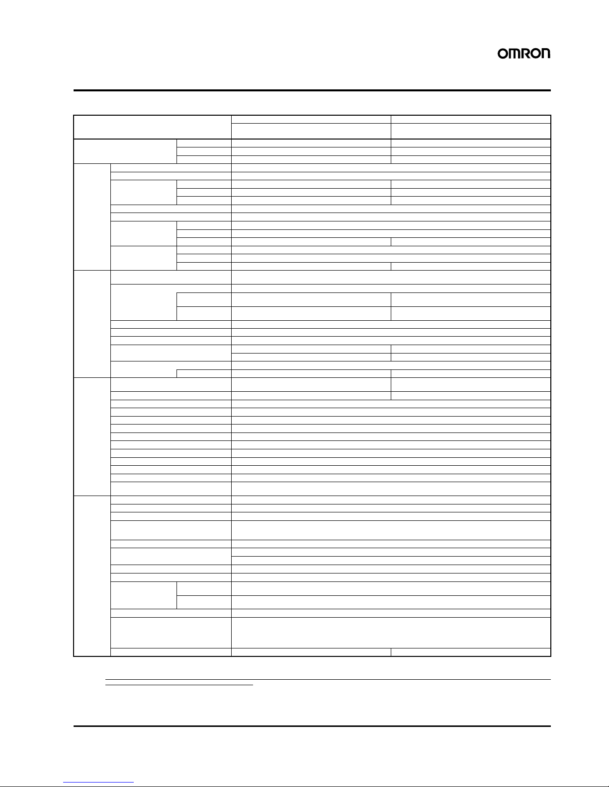
Specifications
■ Ratings/Characteristics
Note: 1. Refer to the Engineering Data section on page 17 for details.
2. If the V.ADJ adjuster is turned, the voltage will increase by more than +15% of the voltage adjustment range. When adjusting the output voltage, confirm the actual output voltage from
the Power Supply and be sure that the load is not damaged.
3. The overvoltage protection of the S8VS-015@@ uses a zener diode clamp. If the internal feedback circuit is destroyed by any chance, the load may be destroyed by the clamped output
voltage (approx. 140% to 190% of the rated output voltage).
4. To reset the protection, turn OFF the power supply for three minutes or longer and then turn the power supply back ON.
5. The typical values indicate the values for an input condition of 230 VAC. All items are measured at a frequency of 50 Hz.
6. The inrush current circuits do not differ for voltage specifications. Therefore, the typical values are the data values for 24-V models.
7. The circuit forms are different, so the start up time is shorter only when using a 15-W power rating.
Power ratings 15 W 30 W
Typ e
Item
Standard Standard
Efficiency (typical) 5-V models 72% min. (76% typ.) 70% min. (76% typ.)
12-V models 74% min. (79% typ.) 76% min. (83% typ.)
24-V models 77% min. (81% typ.) 80% min. (85% typ.)
Input Voltage 100 to 240 VAC (85 to 264 VAC)
Frequency 50/60 Hz (47 to 450 Hz)
Current 100 V input 0.45 A max. 0.9 A max.
200 V input 0.25 A max. 0.6 A max.
230 V input 5 V: (0.14 A typ.), 12 V/24 V (0.19 A typ.) 5 V: (0.27 A typ.), 12 V/24 V (0.37 A typ.)
Power factor --Harmonic current emissions Conforms to EN61000-3-2
Leakage current 100 V input 0.5 mA max.
200 V input 1.0 mA max.
230 V input 5 V/12 V/24 V: (0.30 mA typ.) 5 V/12 V/24 V:(0.32 mA typ.)
Inrush current
(See note 1.)
100 V input 25 A max. (20 A typ.) (for a cold start at 25°C)
200 V input 50 A max. (40 A typ.) (for a cold start at 25°C)
230 V input 5 V/12 V/24 V: (29 A typ.) (See note 6.) 5 V/12 V/24 V: (40 A typ.) (See note 6.)
Output Voltage adjustment range
(See note 2.)
−10% to 15% (with V.ADJ) (guaranteed)
Ripple 2.0% (p-p) max. (at rated input/output voltage)
f=20MHz measuring
5 V: (0.70%(p-p) typ.), 12 V:(0.48%(p-p) typ.), 24 V:(0.25%(p-p)
typ.)
5 V: (0.70%(p-p) typ.), 12 V:(0.52%(p-p) typ.), 24 V:(0.19%(p-p)
typ.)
f=100MHz measuring
5 V: (0.86%(p-p) typ.), 12 V:(0.56%(p-p) typ.), 24 V:(0.32%(p-p)
typ.)
5 V: (0.80%(p-p) typ.), 12 V:(0.58%(p-p) typ.), 24 V:(0.21%(p-p)
typ.)
Input variat ion influence 0.5% max. (at 85 to 264 VAC input, 100% load)
Load variation influence (rated input voltage)
2.0% max. (5 V), 1.5% max. (12 V, 24 V), (with rated input, 0 to 100% load)
Temperature variation influence 0.05%/°C max.
Start up time (See note 1 and 7.) 100 ms max. (at rated input/output voltage) 1,000 ms max. (at rated input/output voltage)
5 V: (6 ms typ.), 12 V: (12 ms typ.), 24 V: (18 ms typ.) 5 V/12 V/24 V: (240 ms typ.)
Hold time (See note 1.) 20 ms min. (at rated input/output voltage)
at 100% load 5 V: (328 ms typ.), 12V: (251 ms typ.), 24 V: (243 ms typ.) 5 V: (299 ms typ.), 12 V: (217 ms typ.), 24 V: (210 ms typ.)
Additional
functions
Overload protection (See note 1.) 105% to 160% of rated load current, voltage drop, automatic re-
set
105% to 160% of rated load current, voltage drop, intermittent
operation, automatic reset
Overvoltage protection (See note 1.) Yes (a zener diode clamp) (See note 3.) Yes (See note 4.)
Output voltage indication No
Output current indication No
Peak-hold current indication No
Maintenance forecast monitor indication
No
Maintenance forecast monitor output No
Total run time monitor indication No
Total run time monitor ou tput No
Undervoltage alarm indication Yes (color: red)
Undervoltage alarm output No
Parallel operation No
Series operation Models with 24-V output: Possible for up to 2 Power Supplies (with external diode)
Models with 5- or 12-V output: Not possible
Other Operating ambient temperature Refer to the derating curve in Engineering Data. (with no icing or condensation)
Storage t emperatu re −25 to 65°C
Operating ambient humidity 25% to 85% (Storage humidity: 25% to 90%)
Dielectric strength 3.0 kVAC for 1 min. (between all inputs and outputs; detection current: 20 mA)
2.0 kVAC for 1 min. (between all inputs and PE terminals; detection current: 20 mA)
1.0 kVAC for 1 min. (between all outputs and PE terminals; detection current: 20 mA)
Insulation resistance 100 MΩ min. (between all outputs and all inputs/ PE terminals) at 500 VDC
Vibration resistance 10 to 55 Hz, 0.375-mm single amplitude for 2 h each in X, Y, and Z directions
10 to 150 Hz, 0.35-mm single amplitude (5 G max.) for 80 min. each in X, Y, and Z directions
Shock resistance
150 m/s2, 3 times each in ±X, ±Y, and ±Z directions
Output indicator Yes (color: green)
EMI Conducted
Emissions
Conforms to EN61204-3 EN55011 Class B and based on FCC Class A
Radiated
Emissions
Conforms to EN61204-3 EN55011 Class B
EMS Conforms to EN61204-3 high severity levels
Approved standards UL: UL508 (Listing, Class 2: Per UL1310), UL60950-1, UL1604 (Class I/Division2)
cUL: CSA C22.2 No.14 (Class 2), No.60950-1, No.213 (Class I/Division2)
EN/VDE: EN50178 (=VDE0160), EN60950-1 (=VDE0805)
SELV (EN60950/EN50178/UL60950-1)
According to VDE0106/P100, IP20
Weight 160 g max. 180 g max.
4 Switch Mode Power Supply S8VS
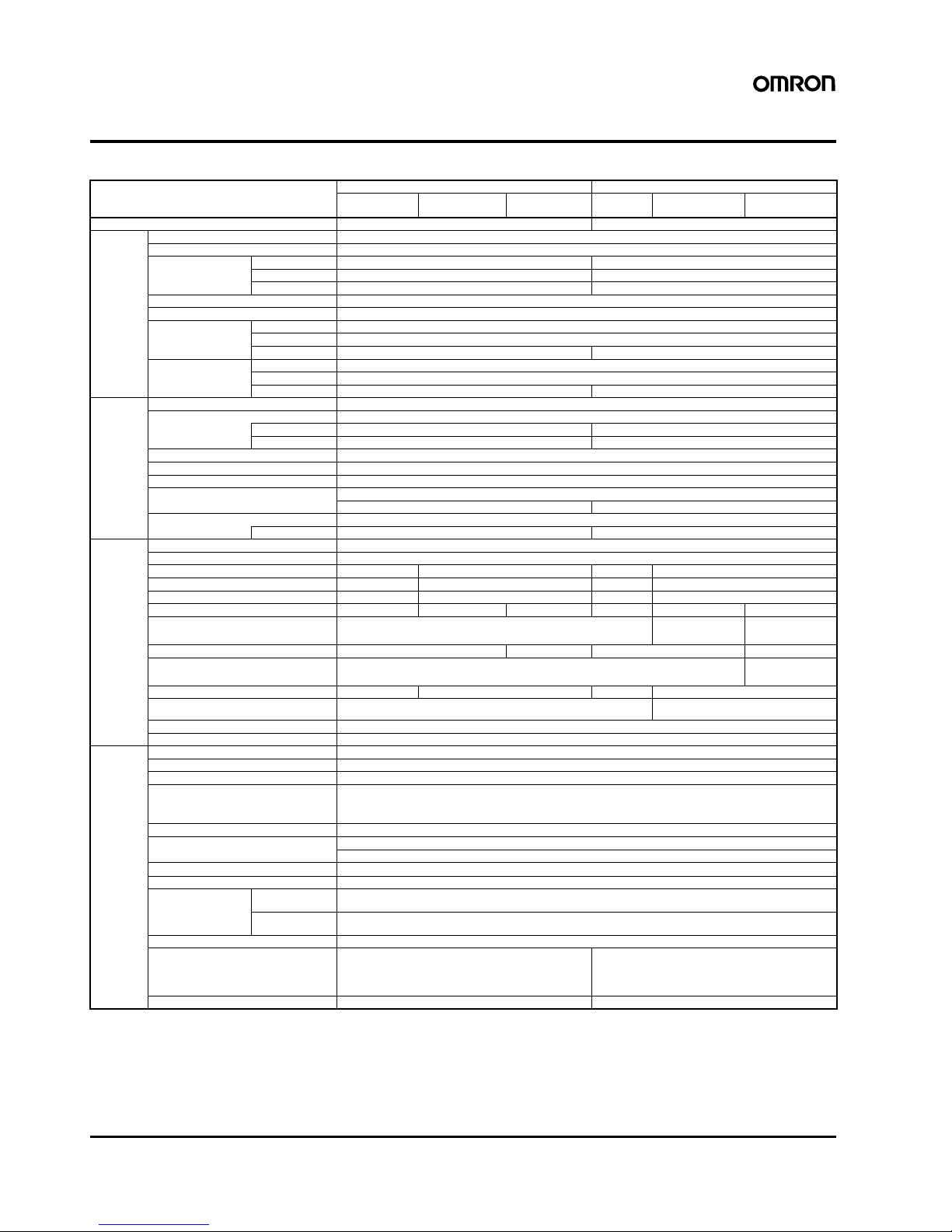
Specifications
■ Ratings/Characteristics
Note: 1. Refer to the Engineering Data section on page 17 for details.
2. If the V.ADJ adjuster is turned, the voltage will increase by more than +15% of the voltage adjustment range (by more than +10% for 240-W models). When adjusting the output voltage,
confirm the actual output voltage from the Power Supply and be sure that the load is not damaged.
3. To reset the protection, turn OFF the power supply for three minutes or longer and then turn the power supply back ON.
4. Displayed on 7-segment LED. (character height: 8 mm)
5. Resolution of output voltage indication: 0.1 V, Precision of output voltage indication: ±2% (percentage of output voltage value, ±1 digit)
6. Resolution of output current indication: 0.1 A; Precision of output current indication: ±5% F.S. ±1 digit max. (specified by rated output voltage)
7. Resolution of peak-hold current indication: 0.1 A; Precision of peak-hold current indication: ±5% F.S. ±1 digit max. (specified by rated output voltage);
Signal width required for peak-hold current: 20 ms
8. A Type and B Type: Sinking, AP Type and P Type: Sourcing
9. To ensure the emission rating, a ferrite ring core should be used in all cabling (TDK HF60T, HF70RH or equivalent model).
10. The typical values indicate the values for an input condition of 230 VAC. All items are measured at a frequency of 50 Hz.
Power ratings 60 W 90 W
Type
Item
Standard Maintenance
forecast monitor
Total run time
monitor
Standard Maintenance
forecast monitor
Total run time
monitor
Efficiency (typical) 78% min. (86% typ.) 80% min. (87% typ.)
Input Voltage 100 to 240 VAC (85 to 264 VAC)
Frequency 50/60 Hz (47 to 450 Hz)
Current 100 V input 1.7 A max. 2.3 A m ax.
200 V input 1.0 A max. 1.4 A max.
230 V input (0.7 A typ.) (0.9 A typ.)
Power factor --Harmonic current emissions Conforms to EN61000-3-2
Leakage current 100 V input 0.5 mA max.
200 V input 1.0 mA max.
230 V input (0.40 mA typ.) (0.35 mA typ.)
Inrush current
(See note 1. )
100 V input 25 A max. (for a cold start at 25°C)
200 V input 50 A max. (for a cold start at 25°C)
230 V input (47 A typ.) (38 A typ.)
Output
Voltage adjustment range (See note 2.)
−10% to 15% (with V.ADJ) (guaranteed)
Ripple 2.0% (p-p) max. (at rated input/output voltage)
f=20MHz meas uring
(0.29% (p-p) typ.) (0.38% (p-p) typ.)
f=100MHz measur ing
(0.32% (p-p) typ.) (0.42% (p-p) typ.)
Input variation influence 0.5% max. (at 85 to 264 VAC input, 100% load)
Load variation influence (rated input voltage)
1.5% max. (with rated input, 0 to 100% load)
Temperature variation influence 0.05%/°C max.
Start up time (See note 1.) 1,000 ms max. (at rated input/output voltage)
(270 ms typ.) (260 ms typ.)
Hold time (See note 1.) 20 ms min. (at rated input/output voltage)
at 100% load (220 ms typ.) (190 ms typ.)
Additional
functions
Overload protection (See note 1.) 105% to 160% of rated load current, voltage drop, intermittent, automatic reset
Overvoltag e protection (See notes 1 and 3.) Ye s
Output voltage indication (See note 4.) No Yes (selectable) (See note 5.) No Yes (selectable) (See note 5.)
Output current indication (See note 4.) No Yes (selectable) (See note 6.) No Yes (selectable) (See note 6.)
Peak-hold current indication (See note 4.) No Yes (selectabl e) (See note 7.) No Yes (selectable) (See note 7.)
Maintenance forecast monitor indication (See note 4.)
No Yes (selectable) No No Yes (selectable) No
Maintenance forecast monitor output No
Ye s (open collector output), 30 VDC max., 50
mA max. (See note 8.)
No
Total run tim e monitor indication (See note 4.)
No Yes (selectable) No Yes (selectable)
Total run time monitor out put No
Yes (open collector output), 30 VDC max., 50
mA max. (See note 8.)
Undervoltage alarm indication (See note 4.) No Yes (selectable) No Yes (selectable)
Undervoltage alarm output terminals No Yes (open collector output)
30 VDC max., 50 mA max. (See note 8.)
Parallel operation No
Series operation Yes for up to 2 Power Supplies (wi th external diode)
Other Operating ambient temperature Refer to the derating curve in Engineering Data. (with no icing or condensation)
Storage temperature −25 to 65°C
Operating ambient humidity 25% to 85% (Storage humidity: 25% to 90%)
Dielectric strength 3.0 kVAC for 1 min. (between all inputs and outputs/ alarm outputs; detection current: 20 mA)
2.0 kVAC for 1 min. (between all inputs and PE terminals; detection current: 20 mA)
1.0 kVAC for 1 min. (between all outputs/ alarm outputs and PE terminals; detection current: 20 mA)
500 VAC for 1 min. (between all outputs and alarm outputs; detection current: 20 mA)
Insulation resistance 100 MΩ min. (between all outputs/ alarm outputs and all inputs/ PE terminals) at 500 VDC
Vibration resistance 10 to 55 Hz, 0.375-mm single amplitude for 2 h each in X, Y, and Z directions
10 to 150Hz, 0.35-mm single amplitude (5 G max.) for 80 min each in-X, Y, and Z directions
Shock resistance
150 m/s2, 3 times each in ±X, ±Y, and ±Z directions
Output indicator Yes (color: green)
EMI Conducted
Emissions
Conforms to EN61204-3 EN55011 Class A and based on FCC Class A
Conforms to EN61204-3 EN55011 Class B (See note 9.)
Radiated
Emissions
Conforms to EN61204-3 EN55011 Class A
Conforms to EN61204-3 EN55011 Class B (See note 9.)
EMS Conforms to EN61204-3 high severity levels
Approved standards UL: UL508 (Listing, Class 2: Per UL1310), UL60950
cUL: CSA C22.2 No.14 (Class 2), No.60950
EN/VDE: EN50178 (=VDE0160), EN60950 (=VDE0805)
SELV (EN60950/EN50178/UL60950-1)
According to VDE0106/P100, IP20
UL: UL508 (Listing), UL60950
cUL: CSA C22.2 No.14, No.60950
EN/VDE: EN50178 (=VDE0160), EN60950 (=VDE0805)
SELV (EN60950/EN50178/UL60950-1)
According to VDE0106/P100, IP20
Weig ht 330 g max. 490 g max.
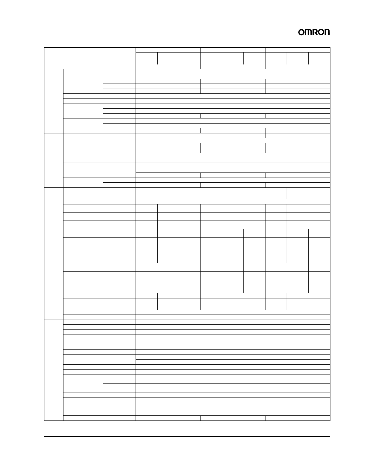
Switch Mode Power Supply S8VS 5
Power ratings 120 W 180 W 240 W
Type
Item
Standard Maintenanc
e forecast
monitor
Tot al ru n
time
monitor
Standard Maintenanc
e forecast
monitor
Tot al ru n
time
monitor
Standard Maintenanc
e forecast
monitor
Tot al run
time
monitor
Efficiency (typical) 80% min. (87% typ.) 80% min. (88% typ.) 80% min. (86% typ.)
Input Voltage 100 to 240 VAC (85 to 264 VAC)
Frequency 50/60 Hz (47 to 63 Hz)
Current 100 V input 1.9 A max. 2.9 A max. 3.8 A max.
200 V input 1.1 A max. 1.6 A max. 2.0 A max.
230 V input (0.6 A typ.) (0.9 A typ.) (1.2 A typ.)
Powe r fa cto r 0.95 min.
Harmonic current emissions Conforms to EN61000-3-2
Leakage current 100 V input 0.5 mA max.
200 V input 1.0 mA max.
230 V input (0.43 mA typ.) (0.45 mA typ.) (0.45 mA typ.)
Inrush current
(See note 1.)
100 V input 25 A max. (for a cold start at 25°C)
200 V input 50 A max. (for a cold start at 25°C)
230 V input (41 mA typ.) (34 mA typ.) (39 mA typ.)
Output Voltage adjustment range (See note 2.) −10% to 15% (with V.ADJ) (guaranteed) ±10% (with V.ADJ) (guaranteed)
Ripple 2.0% (p-p) max. (at rated input/output voltage)
f=20MHz measur ing
(0.66%(p-p) typ.) (0.45%(p-p) typ.) (0.13%(p-p) typ.)
f=100MHz me asuring
(0.67%(p-p) typ.) (0.52%(p-p) typ.) (0.21%(p-p) typ.)
Input variation influence 0.5% max. (at 85 to 264 VAC input, 100% load)
Load variation influence (rated input voltage)
1.5% max. (with rated input, 0 to 100% load)
Temperature variation influence 0.05%/°C max.
Start up time (See note 1.) 1,000 ms max. (at rated input/output voltage)
(380 ms typ.) (530 ms typ.) (780 ms typ.)
Hold time (See note 1.) 20 ms min. (at rated input/output voltage)
at 100% load (60 ms typ.) (60 ms typ.) (30 ms typ.)
Additional functions
Overload protection (S ee note 1.) 105% to 160% of rated load current, voltage drop, intermittent, automatic reset 105% to 160% of rated load
current, voltage drop, automatic reset
Overvoltage protection (See notes 1 and 3.) Yes
Output voltage indication (See note 4.) No Yes (selectable)
(See note 5.)
No Yes (selectable)
(See note 5.)
No Yes (selectable)
(See note 5.)
Output current indication (See note 4.) No Yes (selectable)
(See note 6.)
No Yes (selectable)
(See note 6.)
No Yes (selectable)
(See note 6.)
Peak-hold current indication (See note 4.) No Yes (selectable)
(See note 7.)
No Yes (selectable) (See note
7.)
No Yes (selectable)
(See note 7.)
Maintenance forecast monitor indication
(See note 4.)
No Yes
(selectable)
No No Yes
(selectable)
No No Yes
(selectable)
No
Maintenance forecast monitor output No Yes
(open collector output),
30 VDC
max., 50 mA
max.
(See note 8.)
No No Yes
(open collector output),
30 VDC
max., 50 mA
max.
(See note 8.)
No No Yes
(open collector output),
30 VDC
max., 50 mA
max.
(See note 8.)
No
Total run time monitor indication
(See note 4.)
No Yes
(selectable)
No Yes
(selectable)
No Yes
(selectable)
Total run time monitor output No Yes (open
collector output), 30 VDC
max., 50 mA
max.
(See note 8.)
No Yes (open
collector output), 30 VDC
max., 50 mA
max.
(See note 8.)
No Yes (open
collector output), 30 VDC
max., 50 mA
max.
(See note 8.)
Undervoltage alarm indication (See note 4.) No Yes (selectable) No Yes (selectable) No Yes (selectable)
Undervoltage alarm output terminals No Yes (open collector output),
30 VDC max., 50 mA max.
(See note 8.)
No Yes (open collector output),
30 VDC max., 50 mA max.
(See note 8.)
No Yes (open collector output),
30 VDC max., 50 mA max.
(See note 8.)
Parallel operation No
Series operation Yes for up to 2 Power Supplies (with external diode)
Other Operating ambient temperature Refer to the derating curve in Engineering Data. (with no icing or condensation)
Storage temperature −25 to 65°C
Operating ambient humidity 25% to 85% (Storage humidity: 25% to 90%)
Dielectric strength 3.0 kVAC for 1 min. (between all inputs and outputs/ alarm outputs; detection current: 20 mA)
2.0 kVAC for 1 min. (between all inputs and PE terminals; detection current: 20 mA)
1.0 kVAC for 1 min. (between all outputs/ alarm outputs and PE terminals; detection current: 20 mA)
500 VAC for 1 min. (between all outputs and alarm outputs; detection current: 20 mA)
Insulation resistance 100 MΩ min. (between all outputs/ alarm outputs and all inputs/ PE terminals) at 500 VDC
Vibration resistance 10 to 55 Hz, 0.375-mm single amplitude for 2 h each in X, Y, and Z directions
10 to 150Hz, 0.35-mm single amplitude (5 G max.) for 80 min each in-X, Y, and Z directions
Shock resistance
150 m/s2, 3 times each in ±X, ±Y, and ±Z directions
Output indica tor Yes (color: green)
EMI Conducted
Emissions
Conforms to EN61204-3 EN55011 Class A and based on FCC Class A
Conforms to EN61204-3 EN55011 Class B (See note 9.)
Radiated
Emissions
Conforms to EN61204-3 EN55011 Class A
Conforms to EN61204-3 EN55011 Class B (See note 9.)
EMS Conforms to EN61204-3 high severity levels
Approved standards UL: UL508 (Listing), UL60950
cUL: CSA C22.2 No.14, No.60950
EN/VDE: EN50178 (=VDE0160), EN60950 (=VDE0805)
SELV (EN60950/UL50178/UL60950-1)
According to VDE0106/P100, IP20
Weig ht 550 g max. 850 g max. 1,150 g max.
6 Switch Mode Power Supply S8VS
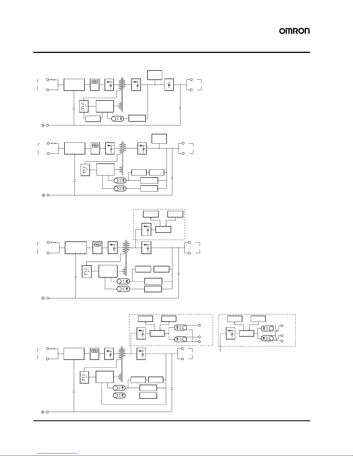
Connections
■ Block Diagrams
Noise filter
AC (L)
INPUT
AC (N)
+V
−V
DC OUTPU
T
Fuse
2.5 A
Voltage
detection circuit
Photocoupler
Drive control
circuit
Overcurrent
detection circuit
Inrush current
protection circuit
Rectifier/
smoothing
circuit
Rectifier/
smoothing
circuit
Undervoltage indicator
Overvoltage
protection
S8VS-015@@ (15-W)
+V
−V
DC OUTPUT
Voltage
detection circuit
Photocoupler
Rectifier/smoothing circuit
Noise filter
AC (L)
INPUT
AC (N)
Drive control
circuit
Fuse 3.15 A
Overcurrent
circuit
Current detection
circuit
Overvoltage
detection circuit
Inrush current protection circuit
Rectifier/
smoothing
circuit
Undervoltage indicator
S8VS-030@@ (30-W)
S8VS-06024 (60-W)
S8VS-06024@ (60-W)
+V
−V
Voltage
detection circuit
Photocoupler
Rectifier/smoothing circuit
Rectifier/smoothing circuit
Rectifier/
smoothing
circuit
Noise filter
AC (L)
INPUT
AC (N)
Drive control
circuit
DC OUTPUT
Fuse 3.15 A
Overcurrent
circuit
Current detection
circuit
Arithmetic
operation circuit
Display circuit
Switch
Overvoltage
detection circuit
S8VS-06024A, S8VS-06024B
Inrush current protection circuit
S8VS-09024 (90-W)
S8VS-09024@@ (90-W)
+V
−V
Voltage
detection circuit
Photocoupler
Photocoupler
Rectifier/smoothing circuit
Rectifier/smoothing circuit
Rectifier/
smoothing
circuit
Noise filter
AC (L)
INPUT
AC (N)
Drive control
circuit
Alarm
DC Low
Yrs/kh
Common
DC OUTPUT
Fuse 4.0 A
Overcurrent
circuit
Arithmetic
operation circuit
Display circuit
Switch
Overvoltage
detection circuit
Current detection
circuit
Rectifier/smoothing circuit
Arithmetic
operation circuit
Display circuit
Switch
Photocoupler
Alarm
DC Low
Yrs/kh
Common
Sinking type (S8VS-09024A, S8VS-09024B) Sourcing type (S8VS-09024AP, S8VS-09024BP)
Inrush current protection circuit
Switch Mode Power Supply S8VS 7
Noise filter
AC (L)
INPUT
AC (N)
+V
Yrs/kh
Common
−V
DC OUTPUT
Fuse 3.5 A
Display circuit Switch
Rectification
Inrush
current
protection
circuit
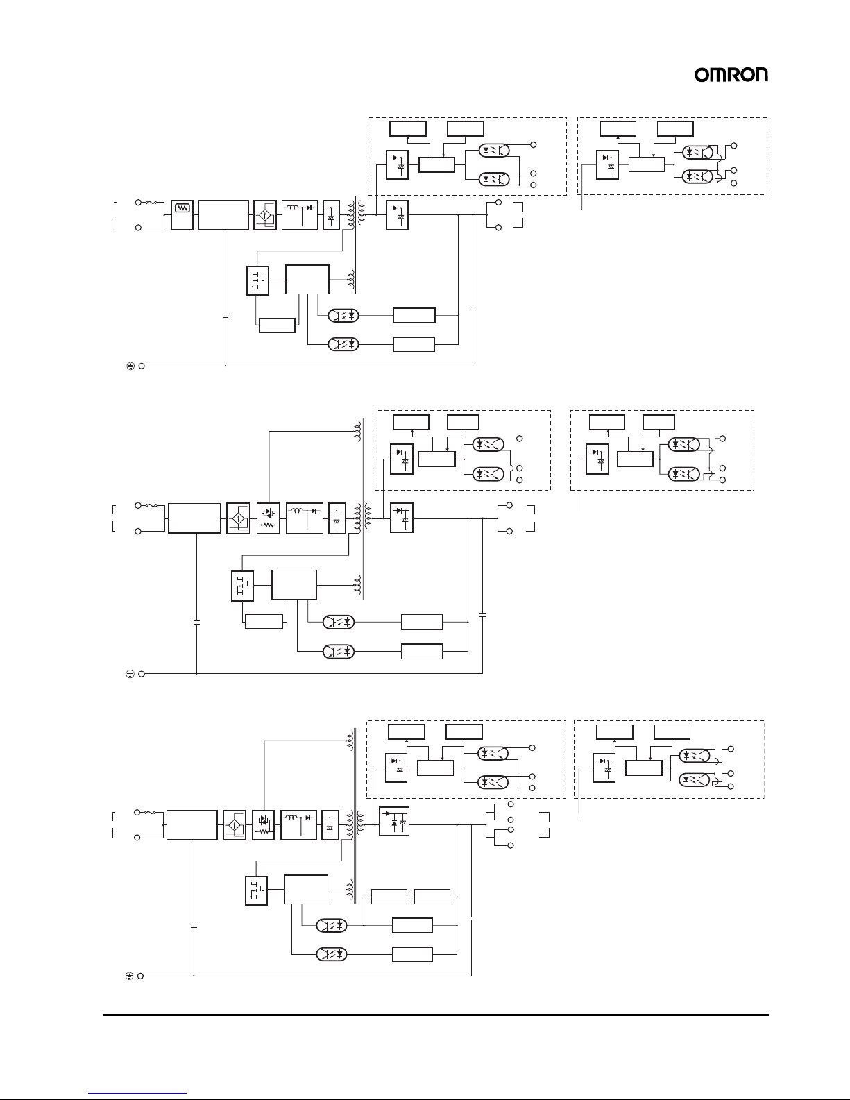
S8VS-12024 (120-W)
S8VS-12024@@ (120-W)
Drive control
circuit
Overcurrent
circuit
Sinking type (S8VS-12024A, S8VS-12024B)
Rectifier/smoothing circuit
Arithmetic
operation circuit
Photocoupler
Alarm
DC Low
Rectifier/smoothing circuit
Photocoupler
Voltage
detection circuit
Overvoltage
detection circuit
Sourcing type (S8VS-12024AP, S8VS-12024BP)
Rectifier/smoothing circuit
Arithmetic
operation circuit
Display circuit
Switch
Photocoupler
Alarm
DC Low
Yrs/kh
Common
Harmonic
current
suppression
Smoothing
Noise filter
AC (L)
INPUT
AC (N)
Yrs/kh
Common
+V
−V
DC OUTPUT
Fuse 6 A
Display circuit
Switch
S8VS-18024 (180-W)
S8VS-18024@@ (180-W)
Inrush current
protection
circuit
Drive control
circuit
Photocoupler
Sinking type (S8VS-18024A, S8VS-18024B)
Sourcing type (S8VS-18024AP, S8VS-18024BP)
Rectifier/smoothing circuit
Arithmetic
operation circuit
Alarm
DC Low
Rectifier/smoothing circuit
Voltage
detection circuit
Overvoltage
detection circuit
Rectifier/smoothing circuit
Arithmetic
operation circuit
Display circuit
Switch
Alarm
DC Low
Yrs/kh
Common
Rectification
Harmonic
current
suppression
Smoothing
Overcurrent
detection circuit
Noise filter
AC (L)
INPUT
AC (N)
+V
Yrs/kh
Common
+V
−V
−V
DC OUTPUT
Fuse 7.5 A
Display circuit Switch
S8VS-24024 (240-W)
S8VS-24024@@ (240-W)
Inrush current
protection
circuit
Drive control
circuit
Photocoupler
Sinking type (S8VS-24024A, S8VS-24024B) Sourcing type (S8VS-24024AP, S8VS-24024BP)
Rectifier/smoothing circuit
Arithmetic
operation circuit
Photocoupler
Alarm
DC Low
Rectifier/smoothing circuit
Overcurrent
circuit
Voltage
detection circuit
Overvoltage
detection circuit
Current detection circuit
Rectifier/smoothing circuit
Arithmetic
operation circuit
Display circuit
Switch
Photocoupler
Alarm
DC Low
Yrs/kh
Common
Rectification Harmonic
current
suppression
Smoothing
8 Switch Mode Power Supply S8VS
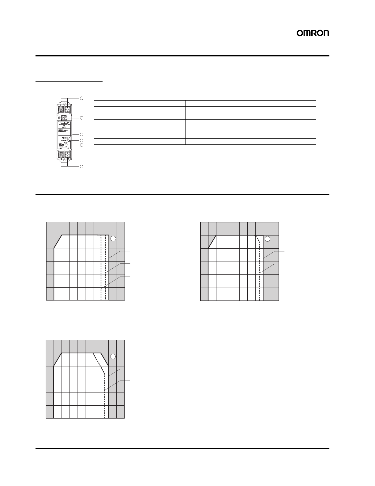
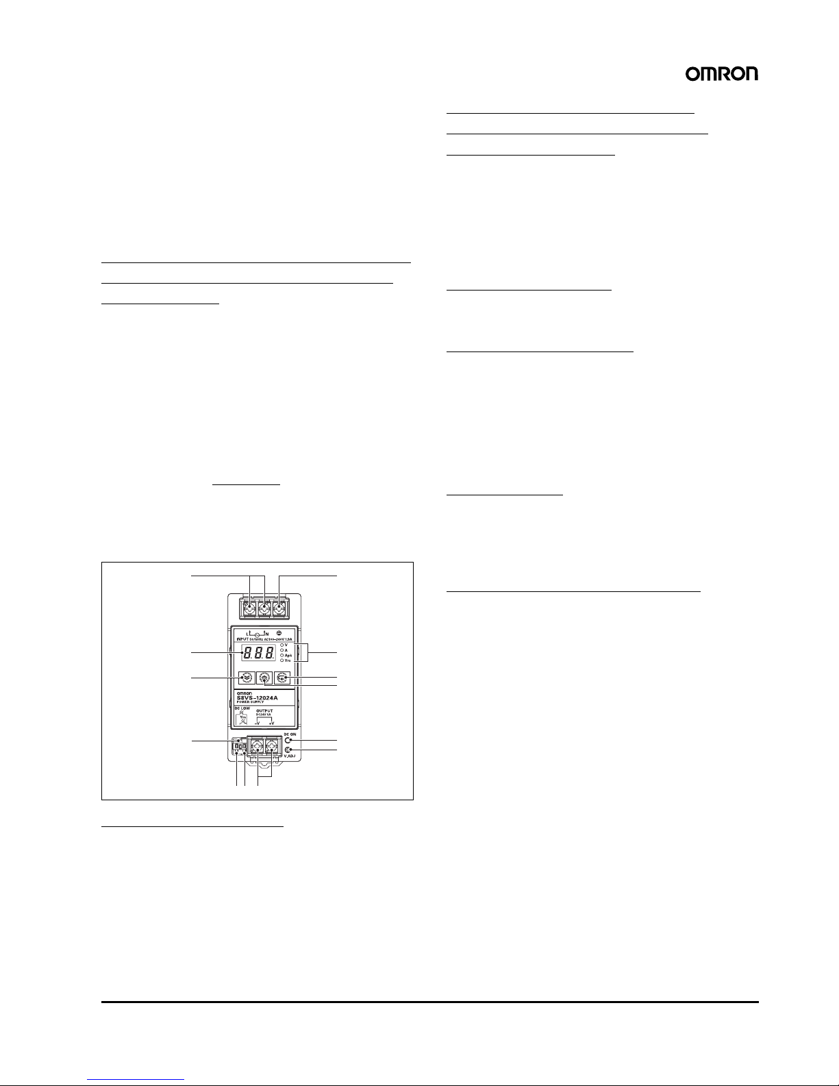
Construction and Nomenclature (15-W, 30-W Models)
■ Nomenclature
15-W, 30-W Models
S8VS-015@@/S8VS-030@@
Note: The S8VS-01505 is shown above.
Engineering Data (15-W, 30-W Models)
■ Derating Curve
S8VS-015@@
S8VS-03005/S8VS-03012
S8VS-03024
Note: 1. Internal parts may occasionally deteriorate or be damaged.
Do not use the Power Supply in areas outside the derating
curve (i.e., the area shown by shading A in the above
graph).
2. If there is a derating problem, use forced air-cooling.
3. Provide a space of at least 20 mm when using standard
mounting and horizontal mounting. If 20 mm is not available,
make sure that the space is at least 10 mm. In this case, reduce the corresponding derating curve by 5
°C.
4. When mounting Power Supplies facing horizontally in a vertical stack, provide a space of at least 75 mm in between the
Power Supplies. If 75 mm is not available, reduce the corresponding derating curve by 1
°C for every 5-mm reduction in
space. A space of at least 25 mm, however, must be provided. In this case, reduce the corresponding derating curve by
10
°C.
1
2
4
5
6
3
Note: 1. The fuse is located on the (L) side. It is NOT user-replaceable.
2. This is the protective earth terminal specified in the safety standards. Always ground this terminal.
No. Name Function
1 AC Input terminals (L), (N) Connect the input lines to these terminals. (See note 1.)
2 Protective Earth terminal (PE) Connect the ground line to this terminal. (See note 2.)
3 DC Output terminals (
−V), (+V) Connect the load lines to these terminals.
4 Output indicator (DC ON: Green) Lights while a direct current (DC) output is ON.
5 Undervoltage indicator (DC LOW: Red) Lights when a drop is detected in the output voltage.
6 Output voltage adjuster (V.ADJ) Use to adjust the voltage.
1
−20 −10 0 10 20 30 40 50 60 70 80
120
100
80
60
40
20
0
*1
*2
*3
1* Standard mounting
2* Horizontal mounting
3* Mounting facing horizontally
Ambient temperature (˚C)
Load ratio (%)
1
−20 −10 0 10 20 30 40 50 60 70 80
120
100
80
60
40
20
0
*1
*2
1* Standard mounting
2* Horizontal mounting/mounting facing horizontally
Ambient temperature (˚C)
Load ratio (%)
1
−20 −10 0 10 20 30 40 50 60 70 80
120
100
80
60
40
20
0
*1
*2
1* Standard mounting
2* Horizontal mountin
g
/mounting facing horizontall
y
Ambient temperature (˚C)
Load ratio (%)
Switch Mode Power Supply S8VS 9
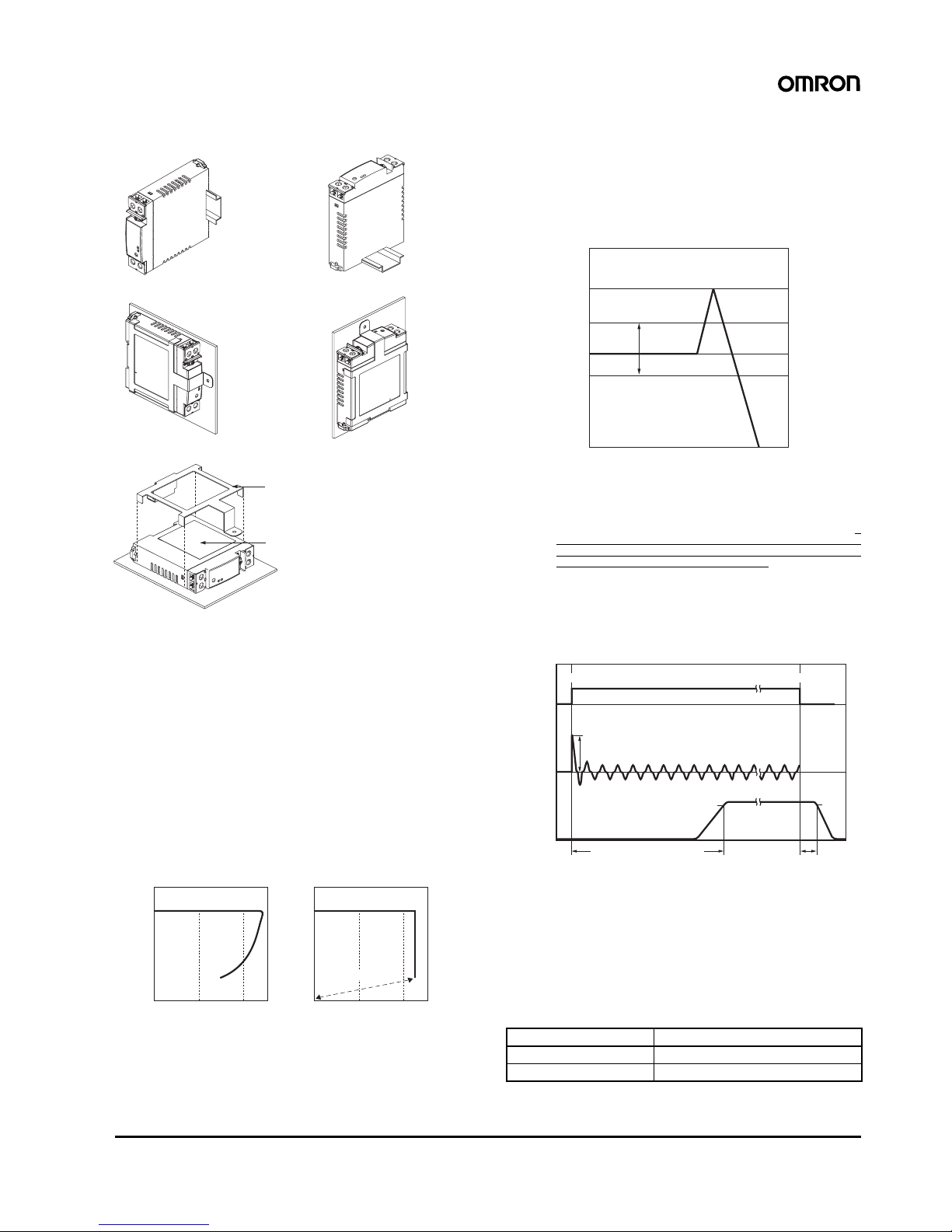
■ Mounting
Note: 1. Improper mounting will interfere with heat dissipation and may
occasionally result in deterioration or damage of internal parts.
Use the product within the derating curve for the mounting direction that is used. Do not use the Power Supply mounted in any
way not shown above.
2. Use a mounting bracket (S82Y-VS30P, sold separately) when
the Product is mounted facing horizontally.
3. Heat dissipation will be adversely affected. When the Product is
mounted facing horizontally, always place the side with the label
facing upward.
4. Use PFP-M End Plates on the top and bottom of the Power Supply when mounting facing horizontally on a DIN rail.
■ Overload Protection
The Power Supply is provided with an overload protection function
that protects the power supply from possible damage by overcurrent.
When the output current rises above 105% min. of the rated current,
the protection function is triggered, decreasing the output voltage.
When the output current falls within the rated range, the overload
protection function is automatically cleared.
Note: 1. Internal parts may occasionally deteriorate or be damaged if a
short-circuited or overcurrent state continues during operation.
2. Internal parts may possibly deteriorate or be damaged if the
Power Supply is used for applications with frequent inrush current or overloading at the load end. Do not use the Power Supply
for such applications.
■ Overvoltage Protection
Consider the possibility of an overvoltage and design the system so
that the load will not be subjected to an excessive voltage even if the
feedback circuit in the Power Supply fails. When an excessive voltage that is approximately 130% of the rated voltage or more is output, the output voltage is shut OFF. Reset the Power Supply by
turning it OFF for at least three minutes and then turning it back ON
again.
Note: 1. Do not turn ON the power again until the cause of the overvolt-
age has been removed.
2. The overvoltage protection of the S8VS-015@@ uses a zener di-
ode clamp. The output voltage will be clamped at approx. 140%
or higher of the rated output voltage (approx. 140% to 190%). If
the internal feedback circuit is destroyed by any chance, the
load may be destroyed by the clamped output voltage (approx.
140% to 190% of the rated output voltage). The power Supply
will not restart if the output is turned OFF by the overvoltage protection operation. If this occurs, replace the Power Supply.
■ Inrush Current, Start Up Time,
Output Hold Time
■ Undervoltage Alarm Indication
LED (DC LOW red) lights to warn of output voltage drop.
Detection voltage is set to approx. 80% (75 to 90%) of the rated output voltage.
Note: This function monitors the voltage at the power supply output termi-
nals. To check actual voltage, measure voltage on the load side.
■ Reference Values
Note: Refer to page 15 for definitions of MTBF and life expectancy.
Horizontal mounting with DIN rail
S82Y-VS30P
Side with label
Mounting facing horizontally with S82Y-VS30P
Standard mounting with DIN rail
Horizontal mounting with S82Y-VS30P
Standard mounting with S82Y-VS30P
Note: The Side-mounting Bracket can be mounted from either side.
0 10050
Output voltage (V)
Output current (%)
0 10050
Output current (%)
Output voltage (V)
Intermittent
operation
15-W Models 30-W Models
The values shown in the above diagrams are for reference only.
Item Value
Reliability (MTBF) 15 W: 610,800 hrs, 30 W: 656,400 hrs
Life expectancy 10 yrs. min.
+15%
−10%
0V
+30%
(approx.)
Overvoltage protection
operating
Variable range
Rated output
voltage
Output voltage (V)
The values shown in the above diagram is for reference only.
90%
96.5%
Start up time (1,000 ms max.)
AC input
voltage
AC input
current
Output
voltage
Inrush current on input application
Input OFF
Input ON
Hold time
(20 ms min.)

10 Switch Mode Power Supply S8VS
Construction and Nomenclature (60-W, 90-W, 120-W, 180-W, and 240-W Models)
■ Nomenclature
Note: 1. The fuse is located on the (L) side. It is NOT user-replace-
able.
2. This is the protective earth terminal specified in the safety
standards. Always ground this terminal.
3. S8VS-@@@24@@ only.
4. S8VS-@@@24@@ only (excluding S8VS-06024@).
5. Both sinking and sourcing outputs are available.
6. S8VS-@@@24A@ only (excluding S8VS-06024A).
7. S8VS-@@@24B@ only (excluding S8VS-06024B).
60-W Models
Standard Model Models with Display Monitor
S8VS-06024 S8VS-06024@
Note: The S8VS-06024A is shown
above.
90-W/120-W Models
Standard Models Models with Display Monitor
S8VS-09024/S8VS-12024
S8VS-09024@@/S8VS-12024@@
Note: The S8VS-12024A is shown
above.
180-W Models
Standard Model Models with Display Monitor
S8VS-18024 S8VS-18024@@
Note: The S8VS-18024A is shown
above.
240-W Models
Standard Model Models with Display Monitor
S8VS-24024 S8VS-24024@@
Note: The S8VS-24024A is shown
above.
1
3
2
4
5
1
3
2
4
8
76
5
3
12
4
5
3
1
131211
2
4
5
8
9
76
10
3
1
2
3
4
5
1
2
3
4
5
1113
6
10
12
7
8
9
4
5
3
12
1311
4
5
8
9
7
12
6
10
3
12
No. Name Function
1 AC Input terminals
(L), (N)
Connect the input lines to these
terminals. (See note 1.)
2 Protective Earth
terminal (PE)
Connect the ground line to this
terminal. (See note 2.)
3 DC Output terminals
(
−V), (+V)
Connect the load lines to these
terminals.
4 Output indicator
(DC ON: Green)
Lights while a direct current (DC)
output is ON.
5 Output voltage
adjuster (V.ADJ)
Use to adjust the voltage.
6 Main display (Red)
(See note 3.)
Indicates the measurement or set
value.
7 Operation
indicator (Orange)
(See note 3.)
V Lights up when the output voltage is
indicated. Blinks during setup of
undervoltage alarm value.
A Lights up during indication of output
current.
Apk Lights up during indication of peak
hold current.
Yrs
Lights up during indication of
maintenance forecast monitor. Blinks
during setup of maintenance forecast
monitor setting. (S8VS-
@@@
24A@)
kh Lights up during indication of total run
time monitor. Blinks during setup of
total run time monitor. (S8VS@@@24B@)
8 Mode Key (See note 3.) Use the Mode Key to change the
indicated parameter or reset the peak
hold current value.
9 Up Key (See note 4.) Use the Up Key to change to the
setting mode or to increase the set
value.
10 Down Key (See note 4.) Use the Down Key to change to the
setting mode or to decrease the set
value.
11 Alarm
outputs
(See
notes 4
and 5.)
Undervoltage
output terminal
(DC Low)
Output when a drop is detected in the
output voltage (voltage drop =
transistor OFF).
12 Maintenance
Forecast
output terminal
(Yrs)
(See note 6.)
Output when the set value for
maintenance is reached (transistor
OFF).
Total run time
output terminal
(kh) (See note
7.)
Output when the set value for total
run time is reached (transistor OFF).
13 Common
terminal
Common terminal (emitter) for
terminals 11 and 12.

Switch Mode Power Supply S8VS 11
Engineering Data (S8VS-@@@24@@ Only)
■ Mode Change
S8VS-@@@24A@ Models (with display monitor) can display the output voltage, output current, peak hold current, or maintenance forecast monitor time. S8VS-@@@24B@ Models (with display monitor) can display the output voltage, output current, peak hold current, or total run time.
Note: No setting mode is provided for the S8VS-06024@.
■ Operation Mode
Various states of the Power Supply are indicated.
Note: 1. The peak hold current starts measuring the current 3 seconds after the Power Supply is started. Inrush current is thus not measured.
2. For the factory setting, the output voltage will be displayed when the power supply is first turned ON. Thereafter, the output voltage will
be indicated in the same display when shutting down.
■ Setting Mode (Except for S8VS-06024@)
Set various parameters of the Power Supply.
Note: 1. Press and hold the (9) Up Key U or (10) Down Key D for two seconds or more to increase or decrease the value rapidly.
2. The S8VS-06024@ is not provided with the setting mode and its parameters are fixed at the shipment setting.
Power-ON
Operation mode
Press Mode key and
hold for three seconds or more.
Or no key operation for 30 seconds or more.
Model indication
Setting mode
Press and hold
Up key
U or Down Key D
for three seconds or more.
Output voltage
(Voltage output by Power Supply is
monitored and displayed.)
Output current
(Current output by Power Supply is
monitored and displayed.)
Peak hold current
(Maximum current output by Power Supply is
recorded and displayed.)
Total run time monitor
Output voltage
(Voltage output by Power Supply is
monitored and displayed.)
Output current
(Current output by Power Supply is
monitored and displayed.)
Peak hold current (See note 1.)
(Maximum current output by Power Supply is
recorded and displayed.)
Maintenance forecast monitor
Models with Maintenance Forecast Monitor (S8VS-@@@24A@) Models with Total Run Time Monitor (S8VS-@@@24B@)
Operation Mode
Undervoltage
detected
Total run
time
1,000-hour steps
*
1 to 50 to 150 ( ×
1000 h)
/
/
Press 3 seconds or more or no key
pressed for 30 seconds or more.
or
Press 3 seconds
or more.
* Factory settings are in
reverse t
yp
e.
Models with Maintenance Forecast Monitor (S8VS-@@@24A@) Models with Total Run Time Monitor (S8VS-@@@24B@)
Operation Mode
Undervoltage
detected
Maintenance
forecast
18.5 to 20.0 to 27.5 (V)
0.1-V steps
* Factory settings are in reverse
type.
*
0.5-year steps
*
0.0 to 0.5 to 5.0 (y)
/
/
Press 3 seconds or more or no key
pressed for 30 seconds or more.
or
Press 3 seconds
or more.
18.5 to 20.0 to 27.5 (V)
0.1-V steps
*

12 Switch Mode Power Supply S8VS
■ Peak Hold Current Reset
The peak value of the output current (i.e., the peak hold current) can
be reset on the display.
Note: The peak hold current value is not reset in the setting mode.
■ Undervoltage Alarm Indication
This indicator lights when the output voltage is insufficient.
Note: 1. The display changes to the output voltage display when the
voltage is restored to the set value or higher.
2. The above displays are for models with a maintenance fore-
cast monitor (S8VS-@@@24A@).
■ Multiple Alarms
When two or more different alarms occur at the same time
Note: 1. When undervoltage alarm is indicated: Press output
load indication When the maintenance forecast monitor or
overheat alarm is indicated: Press undervoltage
alarm indication
2. The above displays are for models with a maintenance fore-
cast monitor (S8VS-@@@24A@).
Operation mode
Peak hold current
value measurement
starts
Reset
2 seconds (Peak hold current will be displayed
2 seconds after it is reset.)
Key Press 3 seconds or more.
Operation
Mode
Output
current
Peak-hold
current
Maintenance
forecast
monitor
Undervoltage
alarm
Undervoltage occurs.
Output voltage lower limit
(See note.)
Note: This indicator alternately
displays alarm ( ) and
the output voltage lower
limit.
Operation
Mode
Undervoltage
alarm
Maintenance
forecast
monitor
The indication shifts
alternately in the directio
n
of the arrow every 2 s.
(See note.)
(See note.)

Switch Mode Power Supply S8VS 13
■ Self-Diagnostics Function
Numbers in the following table indicate the number used in Nomenclature on pages 8 and 10.
Note: 1. External noise is probable as a cause of “
---”, “e01”, “e02” and “e03” errors.
2. Operation out of the derating curve area, ventilation error, and incorrect mounting direction are probable as a cause of “
h%t” error.
3. If the “
h%t” error state continues for more than three hours, the maintenance forecast monitor function becomes invalid. The Yrs output
((12) Maintenance forecast output terminal (Yrs)) will remain OFF (no continuity between (12) Maintenance forecast output terminal (Yrs)
and (13) Alarm output common terminal).
Replace the power supply if this condition occurs even if the output is correct, as internal parts may be deteriorated.
4. The “
h%t” error detection function is only for the S8VS-@@@24A@.
(6) Main display Description Output status Restoration method
Setting after restoration
Noise detected in voltage or current
No change Automatic restoration No change
Overheated (12) Maintenance
forecast output terminal (Yrs) turns
OFF.
Automatic restoration No change
Undervoltage alarm set value
memory error
(11) Undervoltage
output terminal (DC
LOW) turns OFF.
Press and hold the (9) Up Key U or (10)
Down Key D for three seconds and check
the set value of the corresponding point.
The set value must return to the
shipment setting
Shipment setting or
value set in the setting
mode again
Memory error of alarm set value of
maintenance forecast monitor or
total run time monitor
(12) Maintenance
forecast output terminal (Yrs) turns
OFF or total run time
output terminal (kh)
turns OFF.
Other memory error (11) Undervoltage
output terminal (DC
LOW) turns OFF.
(12) Maintenance
forecast output terminal (Yrs) turns
OFF or total run time
output terminal (kh)
turns OFF.
Turn the AC input OFF then ON again.
If the product is not reset, contact the dealer.
No change

14 Switch Mode Power Supply S8VS
■ Maintenance Forecast
(S8VS-@@@24A@)
Displays when the maintenance forecast has reached the set value.
■ Indication and Output
When the product is purchased, “ful” will be indicated. As electrolytic capacitors deteriorate, indication changes to “
hlf”. “ful” will be
indicated for the maintenance forecast display for approximately one
month after the Power Supply is first turned ON. The accumulated
value will then be displayed depending on the ambient conditions
thereafter. (However, the “
hlf” indication may not appear, depending
on the usage environment and the set value for maintenance forecast.)
S8VS-06024A:
After the remaining time to maintenance is reduced to less than two
years, indication automatically changes to a value, which decreases
from “
1.5” to “1.0” to “0.5” to “0.0” (year) as the running hours
increase. If the remaining time becomes less than 0.5 year, an alarm
(
a02) and “0.0” are indicated alternately.
S8VS-09024A@/S8VS-12024A@,
S8VS-18024A@/S8VS-24024A@:
If the maintenance forecast setting L (which can be set arbitrarily
from 0.0 to 5.0 years in 0.5-year steps) is set to a value larger than
two years, the indication automatically changes to a value (L - 0.5)
after the remaining time to maintenance is reduced to the set years,
and an alarm (
a02) and the remaining time are indicated alternately.
If the setting is less than 2.0 years, the indication changes to a value
(1.5) after the remaining time becomes less than two years, and after
the remaining time becomes less than the set time, an alarm (
a02)
and the remaining time (L - 0.5) are indicated alternately.
If the alarm (
a02) and a numeric value are indicated alternately, a
transistor ((12) maintenance forecast output terminal (Yrs)) will turn
OFF to indicate the need for maintenance. (The transistor turns OFF
when the maintenance forecast time is reached, i.e., there will be no
continuity between (12) maintenance forecast output terminal (Yrs)
and (13) alarm output common terminal.)
Note: 1. The remaining time to maintenance is based on continuous
operation, not including the time when the power supply is
turned OFF.
2. “
ful” will be indicated until approximately one month of
time is accumulated to estimate the speed of deterioration
and the output will remain ON (continuity between (12)
maintenance forecast output terminal (Yrs) and (13) alarm
output common terminal).
3. For details on the display, refer to Relationship between In-
dication Value and Outputs of Set Value under Maintenance
Forecast Monitor Function.
Operation
Mode
Output
voltage
Maintenance
forecast
monitor
Remaining time
until replacement
The maintenance forecast
has reached the set value.
Output
current
Peak-hold
current
(See note.)
Note: This indicator alternately
displays alarm ( )
and the maintenance
time until replacement.
In the case that the
remaining time is
reduced to smaller
than 0.5 year and
an alarm is issued.

Switch Mode Power Supply S8VS 15
■ Maintenance Forecast Monitor Function
The Power Supply is equipped with electrolytic capacitors.
The electrolyte inside the electrolytic capacitor penetrates the sealing rubber and evaporates as time passes since it is manufactured,
which causes deterioration of characteristics such as decreasing the
capacitance, etc.
Due to this deterioration of the characteristics of the electrolytic
capacitor, the Power Supply decreases its performance as time
passes.
The maintenance forecast monitor function shows an approximate
period left for maintenance of the Power Supply due to deterioration
of electrolytic capacitors. When the period left for maintenance that
the power supply forecasts reaches the set value, an alarm is indicated and an output signal is triggered.
Use this function to know the approximate replacement timing of the
Power Supply.
Note: The maintenance forecast monitor function indicates an ap-
proximate period left for maintenance, based on deterioration
of the electrolytic capacitor. It does not predict failures caused
by other reasons.
Relationship between Indicated Values and Output of Set Values
■ Principle of Operation
The deterioration speed of the electrolytic capacitor varies considerably according to the ambient temperature. (Generally the speed follows “Rule of Two for every 10°C”; for every 10°C increase in
temperature the rate of degradation doubles according to Arrhenius’s
equation.) The S8VS-@@@24A@ monitors the temperature inside
the power supply, and calculates the amount of deterioration according to the running hours and inside temperature. Judging by this
amount of deterioration, the power supply will give the alarm indication and output when the period left for maintenance reaches the set
value.
Note: 1. Due to degradation of internal electronic parts, replace the
power supply approximately 15 years after purchase even if
indication and output of maintenance forecast monitor are
not issued.
2. The maintenance forecast is accelerated or decelerated according to operating conditions. Periodically check indication.
3. Acceleration or deceleration of the maintenance forecast
may cause the output to repeatedly go ON/OFF.
Only the S8VS-09024A@, S8VS-12024A@, S8VS18024A@, and S8VS-24024A@ are equipped with output.
4. The accuracy of the maintenance forecast function may be
adversely affected by applications in which the AC input is
frequently turned ON/OFF.
■ Reference Values
Note: The maintenance forecast is the service life (the power supply’s
internal temperature is monitored at all times) of the internal
electrolytic capacitor in actual operating conditions, and varies
according to the customer’s operating conditions. 15 years is
taken as the maximum period of the maintenance forecast.
(L−0.5)
5.0
L=2.5
L=0.5
2.5 2.0 1.5 1.0 0.5 0
Initial capacity
"1.0" is displayed on the main display for the
duration that the maintenance forecast up to
replacement satisfies the condition 1.0 ≤ T < 1.5.
In case of setting L between 2.5 and 5 years.
Maintenance forecast monitor output
T: Maintenance time
until replacement
The numerical value
decreases with time.
Main displayCapacity of Capacitor
Capacity level
at replacement
L: Maintenance forecast set value (See note.)
0.0 to 5.0, 0.5 steps
Note: This function can be set only on the S8VS-
09024A@, S8VS-12024A@, S8VS-18024A@,
and S8VS-24024A@.
Reliability
(MTBF)
Value
Standard types • With Maintenance Forecast
Monitor types
• With Total Run Time Monitor types
60 W: 400,000 hrs, 230,000 hrs,
90 W: 390,000 hrs, 200,000 hrs,
120 W: 280,000 hrs, 190,000 hrs,
180 W: 260,000 hrs, 180,000 hrs,
240 W: 220,000 hrs, 160,000 hrs,
Definition MTBF stands for Mean Time Between Failures, which is
calculated according to the probability of accidental device failures, and indicates reliability of devices.
Therefore, it does not necessarily represent a life of the
product.
Life
expectancy
10 yrs. min.
Definition The life expectancy indicates average operating hours
under the ambient temperature of 40°C and a load rate
of 50%. Normally this is determined by the life expectancy of the built-in aluminum electrolytic capacitor.
16 Switch Mode Power Supply S8VS
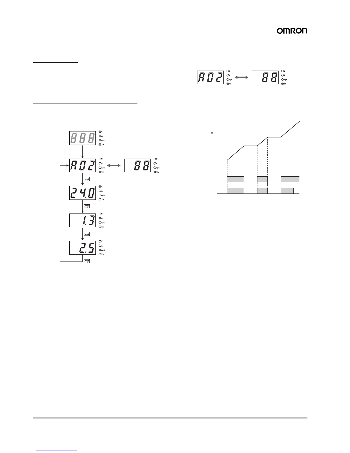
■ Models with Total Run Time Monitor (S8VS-@@@24B@)
S8VS-06024B
The accumulated value of the operating time of the Power Supply is
displayed as the total run time.
0 (kh) will be displayed initially after
purchase and then the display will advance in 1-kh steps as the operating time accumulates. The S8VS-06024B, however, does not have
an alarm function (setting, display, or output).
S8VS-09024B@/S8VS-12024B@/
S8VS-18024B@/S8VS-24024B@
The display will appear when the set value for the total run time has
been reached.
The accumulated value of the operating time of the Power Supply is
displayed as the total run time.
0 (kh) will be displayed initially after
purchase and then the display will advance in 1-kh steps as the operating time accumulates. When the total run time reaches the preset
alarm set value, the alarm (
a02) and the total run time will be dis-
played alternately and a transistor ((12) total run time output terminal
(kh)) will output the status externally.
(Alarm set value reached = OFF, i.e., no continuity between (12) total
run time output terminal (kh) and (13) alarm output common terminal)
The alarm set value can be changed in the setting mode.
Example: Alarm Displays When a Total Run Time Set
Value of 88 kh Is Reached
Note: The total run time cannot be reset. To clear the alarm, change
the alarm set value to a value higher than the value displayed
for the total run time.
Time Chart
Note: Setting is possible for the following models only:
S8VS-09024B@, S8VS-12024B@, S8VS-18024B@,
S8VS-24024B@
Note: 1. The total run time does not include the time that the Power
Supply is OFF.
2. The total run time measures the total time that power is being supplied and is not related in any way to deterioration in
the electrolytic capacitor built into the Power Supply or to the
effects of the ambient temperature.
Operation mode
Total run time
Total run time
Total run time set value reached.
(See note.)
Output
voltage
Output
current
Peak hold
current
Note: The alarm (a02)
and the total run
time will be
displayed
alternately.
Total run time
50 kh
0 kh
AC input
Alarm output
Set value = 50 kh
(See note.)
Switch Mode Power Supply S8VS 17
Engineering Data (60-W, 90-W, 120-W, 180-W, 240-W Models)
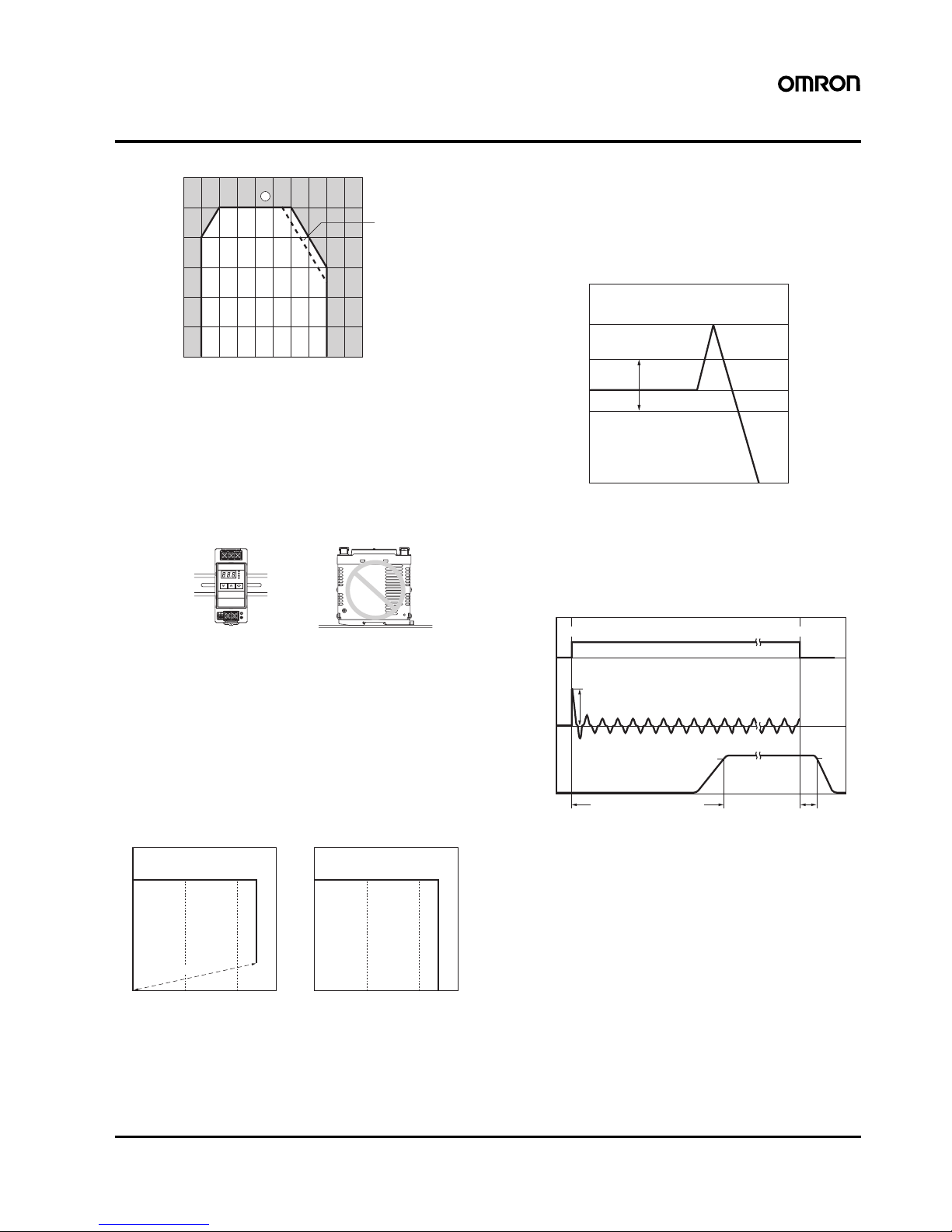
■ Derating Curve
Note: 1. Using side mounting bracket for right-side mounting (ex-
cluding 240-W Models).
2. Internal parts may occasionally deteriorate or be damaged.
Do not use the Power Supply in areas outside the derating
curve (i.e., the area shown by shading A in the above
graph),
3. If there is a derating problem, use forced air-cooling.
■ Mounting
Note: Improper mounting will interfere with heat dissipation and may
occasionally result in deterioration or damage of internal parts.
It may also result in failure of the maintenance forecast monitor
function. Use the standard mounting method only.
■ Overload Protection
The Power Supply is provided with an overload protection function
that protects the power supply from possible damage by overcurrent.
When the output current rises above 105% min. of the rated current,
the protection function is triggered, decreasing the output voltage.
When the output current falls within the rated range, the overload
protection function is automatically cleared.
Note: 1. Internal parts may occasionally deteriorate or be damaged if a
short-circuited or overcurrent state continues during operation.
2. Internal parts may possibly deteriorate or be damaged if the
Power Supply is used for applications with frequent inrush current or overloading at the load end. Do not use the Power Supply
for such applications.
■ Overvoltage Protection
Consider the possibility of an overvoltage and design the system so
that the load will not be subjected to an excessive voltage even if the
feedback circuit in the Power Supply fails. When an excessive voltage that is approximately 130% of the rated voltage or more is output, the output voltage is shut OFF. Reset the Power Supply by
turning it OFF for at least three minutes and then turning it back ON
again.
Note: Do not turn ON the power again until the cause of the overvolt-
age has been removed.
■ Inrush Current, Start Up Time,
Output Hold Time
−20 −10 0 10 20 30 40 50 60 70 80
120
100
80
60
40
20
0
Load (%)
Ambient temperature (˚C
)
See note 1.
1
Upper
Upper
Standard mounting Face-up mounting
Correct Incorrect
050100 0 50 100
Output current (%)
Output voltage (V)
Output current (%)
Output voltage (V)
Intermittent operation
60-W/90-W/120-W/180-W Models 240-W Models
The values shown in the above diagrams are for reference only.
+15%
−10%
0V
+30%
(approx.)
Overvoltage protection
operating
Variable range
Rated output
voltage
Output voltage (V)
The values shown in the above diagram is for reference only.
90%
96.5%
Start up time (1,000 ms max.)
AC input
voltage
AC input
current
Output
voltage
Inrush current on input application
Input OFF
Input ON
Hold time
(20 ms min.)

18 Switch Mode Power Supply S8VS
■ Undervoltage Alarm Function (Indication and Output)
(S8VS-@@@24@@ Only)
When output voltage drop is detected, an alarm (a01) and lowest
output voltage value are indicated alternately. The preset value of
detection voltage can be changed in the setting mode.
(From 18.5 to 27.5 V (18.5 to 26.3 V for the S8VS-24024@@), in 0.1V steps. The value is fixed at 20.0 V for the S8VS-06024@.)
Further, an output ((11) undervoltage output terminal (DC LOW)) to
an external device is given from the transistor to notify of the error
(excluding S8VS-06024@). (Output voltage drop = OFF, i.e., no continuity between (11) undervoltage output terminal (DC LOW) and (13)
alarm output common terminal.)
Example: Outputting an Alarm When the Voltage Output
by the S8VS-09024@@ Drops to the Set Value (19.0 V) or
Lower
:
Note: 1. Operation begins after about three seconds since the AC
power is supplied.
2. The alarm is not indicated in the setting mode.
3. Press the ((8) Mode Key) after the output voltage is re-
stored, to reset alarm indication.
4. The undervoltage alarm function monitors the output terminal voltage of the Power Supply. To check the voltage accurately, measure the voltage at the load end.
Note: 1. Operation begins after about three seconds since the AC
power is supplied.
2. The undervoltage alarm function may also operate when an
interruption in AC input is not restored within 20 ms.
In the case that the
output voltage drops
below the set value (19.0 V)
and an alarm is issued
AC input
Output
voltage
Undervoltage
output
Main display Voltage indication
Detection value
of Undervoltage
alarm
Operation
mode
Lowest value of
output voltage
Switch Mode Power Supply S8VS 19
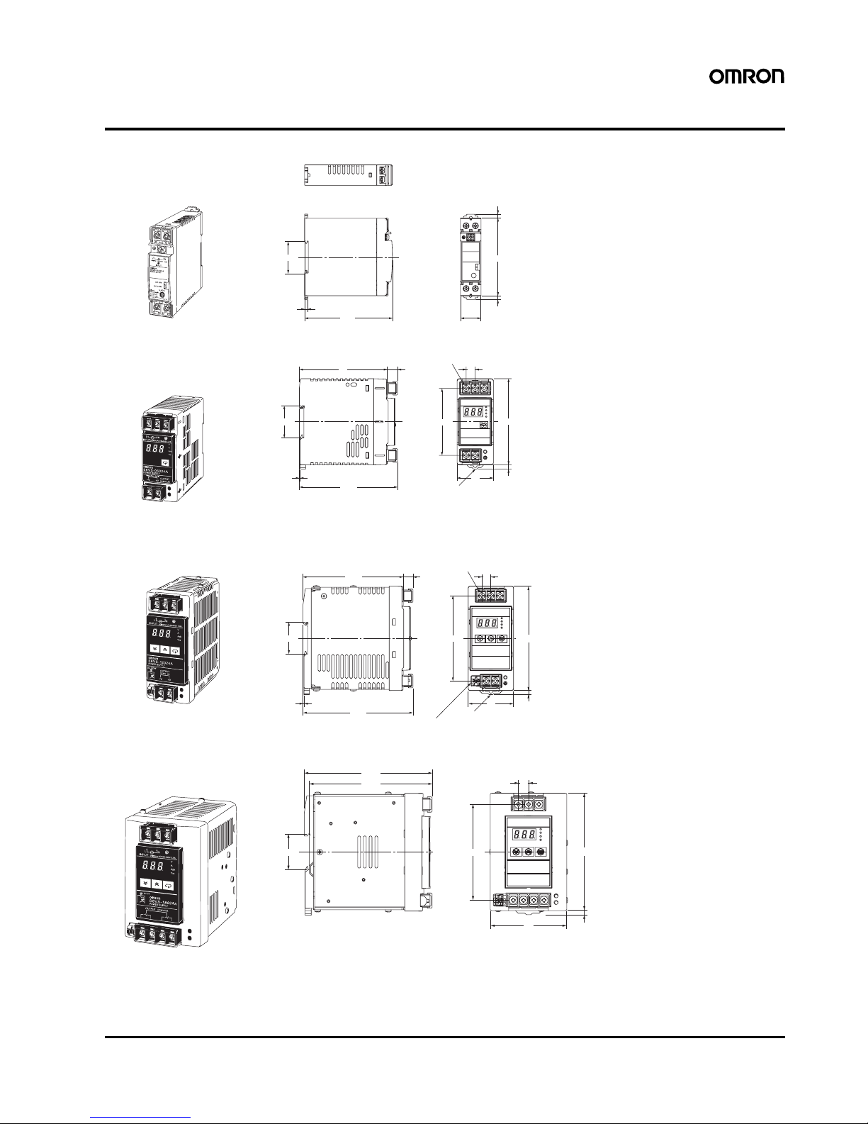
Dimensions
Note: All units are in millimeters unless otherwise indicated.
Note: The illustration is the S8VS-03024 Model.
Note: The illustration is the S8VS-06024A Model.
Note: The illustration is the S8VS-12024A Model.
Note: The illustration is the S8VS-18024A Model.
S8VS-015@@ (15-W)
S8VS-030@@ (30-W)
4.8
(Sliding: 10 max.)
4.8
(Sliding: 10 max.)
35.2
96.4
22.5
4
85
97
11.3
35.4
108.3
1
40
10
74
95
Five, M4
with square washer
Track stopper
4.5
(Sliding: 15 max.
)
S8VS-06024 (60-W)
S8VS-06024@ (60-W)
110.5
10.8
34.9
121.3
1
94
115
10
50
Five, M4
with square washer
Track stopper
Screwless block (2.5 mm pitches)
4.5
(Sliding: 15 max.)
S8VS-09024 (90-W)/S8VS-12024 (120-W)
S8VS-09024@@ (90-W)/S8VS-12024@@ (120-W)
94
115
10
75
4.5
125.3
120.3
34.9
S8VS-18024 (180-W)
S8VS-18024@@ (180-W)
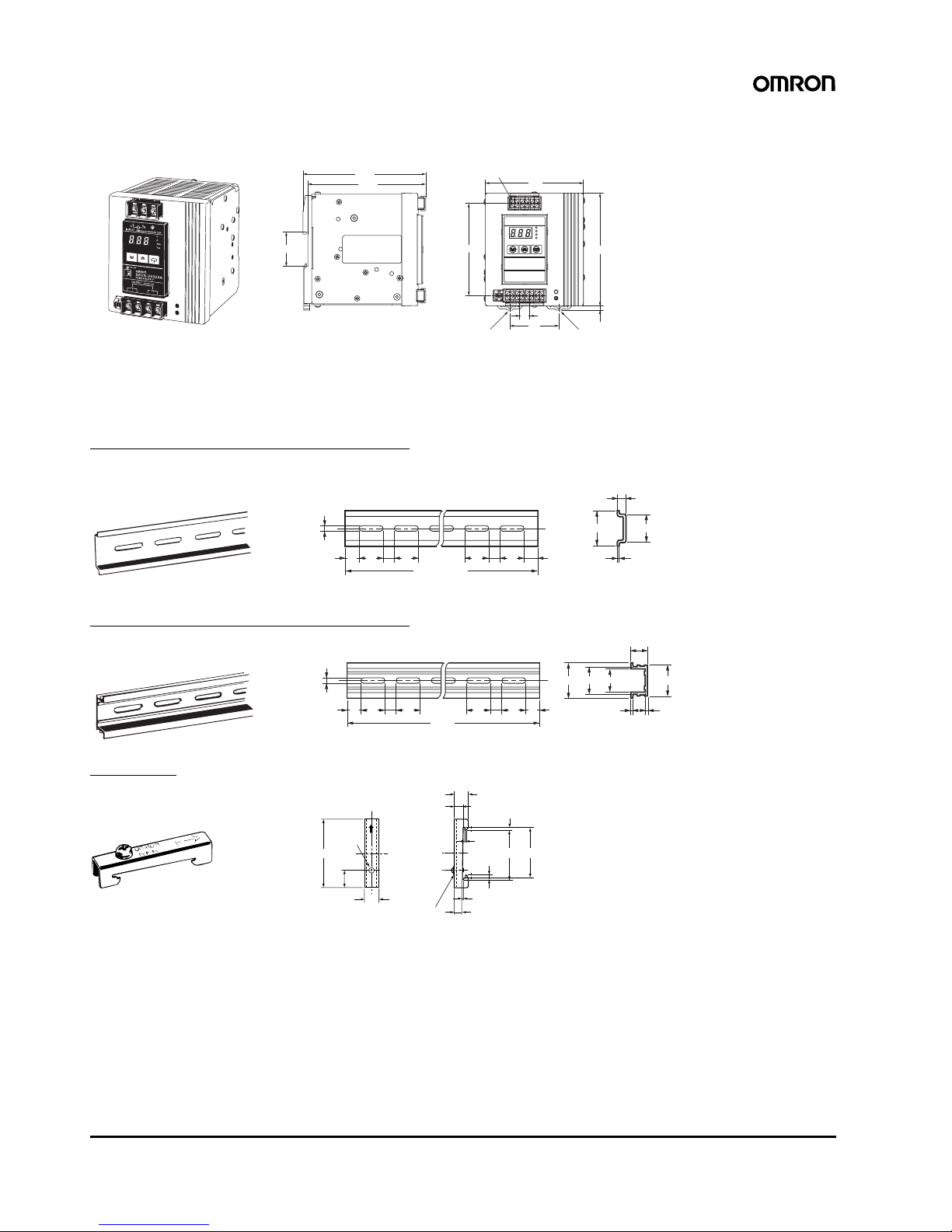
20 Switch Mode Power Supply S8VS
Note: The illustration is the S8VS-24024A Model.
■ DIN Rail (Order Separately)
Note: All units are in millimeters unless otherwise indicated.
Mounting Rail (Material: Aluminum)
Mounting Rail (Material: Aluminum)
End Plate
125.3
120.3
34.9
10
50
94
100
115
Seven, M4
with square washer
Track stopper
4.5 (Sliding: 15 max.)
S8VS-24024 (240-W)
S8VS-24024@@ (240-W)
Track stopper
4.5
15 25 25
10 10
1,000 (500) *
25 25 15(5) *
35
±
0.3
7.3
±
0.15
27
±
0.15
1
*Values in parentheses
are for the PFP-50N.
PFP-100N
PFP-50N
4.5
15 25 25
10 10
1,000
25 25 15
1 1.5
29.2242735
±
0.3
16
PFP-100N2
1.3
4.8
35.5
35.5
1.8
1.8
10
6.2
1
50
11.5
10
PFP-M
M4 spring washer
M4×8 pan-
head screw
Switch Mode Power Supply S8VS 21
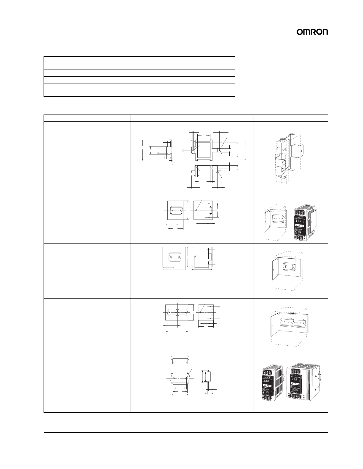
■ Mounting Brackets
Note: Two required to mount a 240-W model.
Name Model
Side-mounting Bracket (for 15- and 30-W models) S82Y-VS30P
Side-mounting Bracket (for 60-, 90-, and 120-W models) S82Y-VS10S
Side-mounting Bracket (for 180-W models) S82Y-VS15S
Side-mounting Bracket (for 240-W models) S82Y-VS20S
Front-mounting Bracket (for 60-, 90-, 120-, 180-, and 240-W models) (See note.) S82Y-VS10F
Type Model Dimensions Appearance
Side-mounting Bracket
(For 15-, 30-W models)
S82Y-VS30P
Side-mounting Bracket
(For 60-, 90-, 120-W models)
S82Y-VS10S
Side-mounting Bracket
(For 180-W models)
S82Y-VS15S
Side-mounting Bracket
(For 240-W models)
S82Y-VS20S
Front-mounting Bracket
(For 60-, 90-, 120-, 180-,
and 240-W models)
S82Y-VS10F
11.25
12.5
Two, 3.5 dia.
7.1
7
5
63
4-R5
R1.75
8-C1
4-R1
R0.2
R1
R1
R0.2
3.5
8
8
0.5
2.5
15
15
63.5
93.6
±
0.1
109.4
±
0.1
11
85.4
±
0.1
34
±
0.1
53
15
0
±0.2
Note: 1. Direction of the return section:
Inside of the bend
2. Height of the return section:
0.1 max.
3. Radius of the inside of the
bend: R2
4. An
g
le of the bend: 90˚±1˚
28
22.5
±
0.1
35
64
t = 2.0
80
60
55
±0.1
13
4.5 dia.
±0.1
Left-side mounting Right-side mounting
t = 2.0
89
78
55 ±0.1
47.5
4.5 dia ±0.1
80
60 ±0.1
Left-side mounting
*Right-side mounting also possible.
60
±0.1
55
±0.1
13
80
78
114
4.5 dia.
±0.1
t = 2.0
60
Left-side mounting
*Right-side mounting also possible.
41
35
±0.1
40
50
4.5 dia.±0.1
35
25
10
7.3
(For 60-, 90-, 120-,
180-W types)
(For 240-W type)
*Use two S82Y-VS10F
brackets for the 240-W type.
22 Switch Mode Power Supply S8VS
Safety Precautions
■ Precautions for Safe Use
Mounting
Take adequate measures to ensure proper heat dissipation to
increase the long-term reliability of the product. Be sure to allow
convection in the atmosphere around devices when mounting. Do
not use in locations where the ambient temperature exceeds the
range of the derating curve.
When cutting out holes for mounting, make sure that cuttings do not
enter the interior of the products.
(15-W and 30-W Models)
Improper mounting will interfere with heat dissipation and may occasionally result in deterioration or damage of internal parts. Use the
product within the derating curve for the mounting direction that is
used.
Use a mounting bracket when the product is mounted facing horizontally.
Heat dissipation will be adversely affected. When the product is
mounted facing horizontally, always place the side with the label facing upward.
Always provide a space of 20 mm even when mounting horizontally
or facing horizontally. If a space of 20 mm is not available, at least 10
mm must be provided. When mounting Power Supplies facing horizontally in a vertical stack, provide a space of at least 75 mm in
between the Power Supplies. For details, refer to Derating Curve on
page 8.
(60-W, 90-W, 120-W, 180-W and 240-W
Models)
Improper mounting will interfere with heat dissipation and may occasionally result in deterioration or damage of internal par ts. Use the
standard mounting method only.
Wiring
Connect the ground completely. A protective earthing terminal
stipulated in safety standards is used. Electric shock or malfunction
may occur if the ground is not connected completely.
Minor fire may possibly occur. Ensure that input and output terminals
are wired correctly.
Do not apply more than 100 N force to the terminal block when
tightening it.
Be sure to remove the sheet covering the product for machining
before power-ON so that it does not interfere with heat dissipation.
Use the following material for the wires to be connected to the S8VS
to prevent smoking or ignition caused by abnormal loads.
Recommended Wire Type
15-W and 30-W Models
60-W, 90-W, 120-W, 180-W and 240-W Models
Installation Environment
Do not use the Power Supply in locations subject to shocks or
vibrations. In particular, install the Power Supply as far away as
possible from contactors or other devices that are a vibration source.
Install the Power Supply well away from any sources of strong,
high-frequency noise and surge.
Operating Life
The life of a Power Supply is determined by the life of the electrolytic
capacitors used inside. Here, Arrhenius’s Law applies, i.e., the life
will be cut in half for each rise of 10°C or the life will be doubled for
each drop of 10°C. The life of the Power Supply can thus be
increased by reducing its internal temperature.
Ambient Operating and Storage
Environments
Store the Power Supply at a temperature of −25 to 65°C and a
humidity of
−25% to 90%.
Do not use the Power Supply in areas outside the derating curve
otherwise, internal parts may occasionally deteriorate or be
damaged.
Use the Power Supply at a humidity of 25% to 85%.
Minor electric shock, fire, or Product failure may
occasionally occur. Do not disassemble, modify, or repair
the Product or touch the interior of the Product.
Minor burns may occasionally occur. Do not touch the
Product while power is being supplied or immediately
after power is turned OFF.
Fire may occasionally occur. Tighten terminal screws to
the specified torque (15 and 30 W Models: 0.8 to 1.0 N·m
60, 90,120, 180, and 240 W Models: 1.08 N·m).
Minor injury due to electric shock may occasionally occur.
Do not touch the terminals while power is being supplied.
Always close the terminal cover after wiring.
Minor electric shock, fire, or Product failure may
occasionally occur. Do not allow any pieces of metal or
conductors or any clippings or cuttings resulting from
installation work to enter the Product.
!CAUTION
*1
*2
*1. Convection of air
*2. 20 mm min.
If 20 mm is not
available, however,
at least 10 mm must
be provided.
Model Stranded wire Solid wire
S8VS-03005 AWG18 to 14
(0.9 to 2.0 mm
2
)
AWG18 to 16
(0.9 to 1.1 mm2)
Other models AWG20 to 14
(0.5 to 2.0 mm
2
)
AWG20 to 16
(0.5 to 1.1 mm2)
Model Recommended wire size
For screw terminal For alarm output
terminal
S8VS-06024@ AWG14 to 20
(Cross section 0.517 to
2.081mm
2
)
---
S8VS-09024@@
S8VS-12024@@
S8VS-18024@@
S8VS-24024@@
AWG14 to 18
(Cross section 0.823 to
2.081mm
2
)
AWG18 to 28
(Cross section 0.081 to
0.823mm2)
Switch Mode Power Supply S8VS 23
Do not use the Power Supply in locations subject to direct sunlight.
Do not use locations where liquids, foreign matter, or corrosive gases
may enter the interior of products.
S8VS-@@@24A@ Models only
Satisfy the following conditions when storing the Power Supply for
long periods of time to maintain its remaining service life function.
• When storing for more than three months, store within an ambient
temperature range of
−25 to +30°C and the humidity range of 25%
to 70%.
Periodic Check (S8VS-09024@@, S8VS-
12024@@, S8VS-18024@@ and S8VS-
24024@@ only)
It may take from several years to more than 10 years under general
operating conditions for the power supply to output the maintenance
forecast monitor alarm (S8VS-@@@24A@). The total run time
monitor (S8VS-@@@24B@) may be a similar number of years as the
maintenance forecast monitor according to some settings. During
operation over an extended period of time, periodically check if the
maintenance forecast monitor output ((12)Yrs) or total run time
monitor output ((12)kh) is correctly functioning by the following
procedure.
1. Select the operation mode.
2. Check that the output ((12)Yrs/kh) is turned ON (with continuity
between (12) and (13)).
3. In the operation mode, press and hold the Down Key D (10) and
the Mode Key M (8) simultaneously
for at least three seconds.
The main display (6) changes to “
a02.”
An inactive output ((12)Yrs/kh) (no continuity between (12) and
(13)) in the “
a02” indication indicates the correct function.
4. Release keys to return to the regular state.
Note: DC output stays ON during the periodical check.
Overcurrent Protection
Internal parts may possibly deteriorate or be damaged if a
short-circuited or overcurrent state continues during operation.
Internal parts may possibly deteriorate or be damaged if the Power
Supply is used for applications with frequent inrush current or overloading at the load end. Do not use the Power Supply for such applications.
Alarm Output (S8VS-09024@@,
S8VS-12024@@, S8VS-18024@@,
S8VS-24024@@ Only)
When using the alarm output, sufficiently consider the maximum
ratings, residual voltage, and leakage current.
Transistor output: Sinking for S8VS-@@@24@ Models
Sourcing for S8VS-@@@24@P Models
30 VDC max., 50 mA max.
ON residually voltage: 2 V max.
OFF leakage current: 0.1 mA max.
Charging the Battery
If a battery is to be connected as the load, mount an overcurrent
limiting circuit and an overvoltage protection circuit.
Dielectric Strength Test
If a high voltage is applied between an input and the case (FG), it will
pass though the LC of the built-in noise filter and energy will be
stored. If the high voltages used for dielectric strength testing are
turned ON and OFF with a switch, timer, or similar device, impulse
voltage will be generated when the voltage is turned OFF and
internal parts may possibly be damaged. To prevent the generation
of impulse voltages, reduce the applied voltage slowly with a variable
resistor on the test device or turn the voltage ON and OFF at the
zero-cross point.
Inrush Current
When two or more Power Supplies are connected to the same input,
the total current is the sum of the currents for each Supply. Select
fuses and circuit breakers giving sufficient consideration to the fusing
or operating characteristics so that fuses will not burn and breakers
will not break due to inrush current.
Output Voltage Adjuster (V.ADJ)
The output voltage adjuster (V.ADJ) may possibly be damaged if it is
turned with unnecessary force. Do not turn the adjuster with
excessive force.
After completing output voltage adjustment, be sure that the output
capacity or output current does not exceed the rated output capacity
or rated output current.
15-W, 30-W Models
If the output voltage is set to a value less than −10%, the undervoltage
alarm function may operate.
60-W, 90-W, 120-W, 180-W, and 240-W Models
If the output voltage is set to a value less than 20 V (the factory
setting), the undervoltage alarm function may operate.
1
131211
2
4
5
8
9
76
10
3
24 Switch Mode Power Supply S8VS
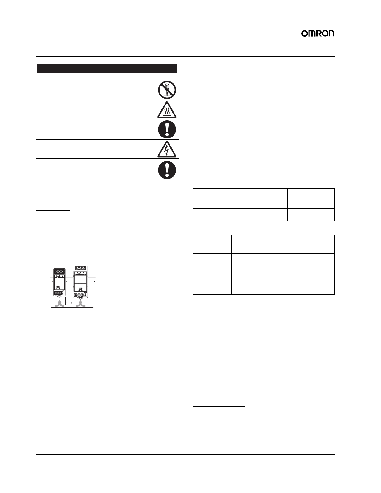
DIN Rail Mounting
To mount the Block on a DIN rail, hook portion (A) of the Block onto
the rail and press the Block in direction (B).
To dismount the Block, pull down portion (C) with a flat-blade
screwdriver and pull out the Block.
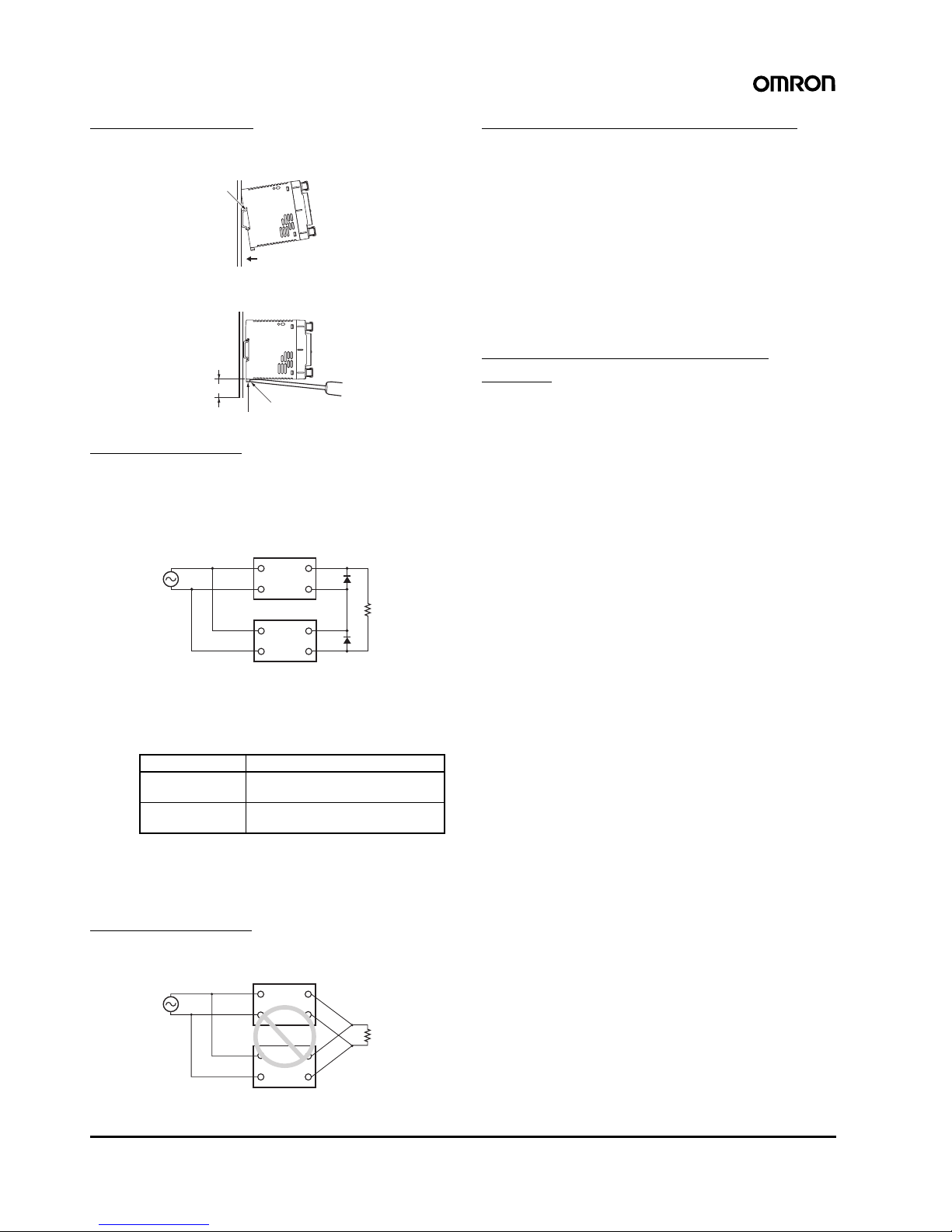
Series Operation
(24-V Model)
Two power supplies can be connected in series.
The (±) voltage output can be accomplished with two power supplies.
Note: 1. The diode is connected as shown in the figure. If the load is
short-circuited, a reverse voltage will be generated inside
the Power Supply. If this occurs the Power Supply may
possibly deteriorate or be damaged. Always connect a
diode as shown in the figure.
Select a diode having the following ratings.
2. Although products having different specifications can be
connected in series, the current flowing through the load
must not exceed the smaller rated output current.
3. Serial operation is not possible with 5-V and 12-V Models.
Parallel Operation
The product is not designed for parallel operation.
In Case There Is No Output Voltage
The possible cause for no output voltage may be that the overcurrent
or overvoltage protection has operated. The internal protection may
operate if a large amount of surge voltage such as a lightening surge
occurs while turning ON the power supply.
In case there is no output voltage, please check the following points
before contacting us:
• Checking overload protected status:
Check whether the load is in overload status or is short-circuited.
Remove wires to load when checking.
• Checking overvoltage or internal protection (except for 15-W
Models):
Turn the power supply OFF once, and leave it OFF for at least 3
minutes. Then turn it ON again to see if this clears the condition.
Harmonic Current Suppression
Circuits
(120-W, 180-W and 240-W Models)
A harmonic current suppression circuit is built into the Power Supply.
This circuit can create noise when the input is turned ON, but it will
last only until the internal circuits stabilize and does not indicate any
problem in the product.
Type Schottky Barrier diode
Dielectric strength
(V
RRM)
Twice the rated output voltage or
above
Forward current
(I
F)
Twice the rated output current or
above
B
A
C
30 mm min.
Track stopper
+V
−V
+V
−V
Correct
AC (L)
AC (N)
AC (L)
AC (N)
+V
−V
+V
−V
Incorrect
AC (L)
AC (N)
AC (L)
AC (N)

Switch Mode Power Supply S8VS 25

26 Switch Mode Power Supply S8VS

Switch Mode Power Supply S8VS 27

28
In the interest of product improvement, specifications are subject to change without notice.
ALL DIMENSIONS SHOWN ARE IN MILLIMETERS.
To convert millimeters into inches, multiply by 0.03937. To convert grams into ounces, multiply by 0.03527.
Cat. No. T030-E1-02A
OMRON Corporation
Industrial Automation Company
Industrial Devices and Components Division H.Q.
Power Electronics Department
Shiokoji Horikawa, Shimogyo-ku,
Kyoto, 600-8530 Japan
Tel: (81)75-344-7108/Fax: (81)75-344-7189
1104
Warranty and Application Considerations
Read and Understand this Catalog
Please read and understand this catalog before purchasing the products. Please consult your OMRON representative if you
have any questions or comments.
Warranty and Limitations of Liability
WARRANTY
OMRON's exclusive warranty is that the products are free from defects in materials and workmanship for a period of one year (or
other period if specified) from date of sale by OMRON.
OMRON MAKES NO WARRANTY OR REPRESENTATION, EXPRESS OR IMPLIED, REGARDING NON-INFRINGEMENT,
MERCHANTABILITY, OR FITNESS FOR PARTICULAR PURPOSE OF THE PRODUCTS. ANY BUYER OR USER
ACKNOWLEDGES THAT THE BUYER OR USER ALONE HAS DETERMINED THAT THE PRODUCTS WILL SUITABLY MEET
THE REQUIREMENTS OF THEIR INTENDED USE. OMRON DISCLAIMS ALL OTHER WARRANTIES, EXPRESS OR
IMPLIED.
LIMITATIONS OF LIABILITY
OMRON SHALL NOT BE RESPONSIBLE FOR SPECIAL, INDIRECT, OR CONSEQUENTIAL DAMAGES, LOSS OF PROFITS,
OR COMMERCIAL LOSS IN ANY WAY CONNECTED WITH THE PRODUCTS, WHETHER SUCH CLAIM IS BASED ON
CONTRACT, WARRANTY, NEGLIGENCE, OR STRICT LIABILITY.
In no event shall the responsibility of OMRON for any act exceed the individual price of the product on which liability is asserted.
IN NO EVENT SHALL OMRON BE RESPONSIBLE FOR WARRANTY, REPAIR, OR OTHER CLAIMS REGARDING THE
PRODUCTS UNLESS OMRON'S ANALYSIS CONFIRMS THAT THE PRODUCTS WERE PROPERLY HANDLED, STORED,
INSTALLED, AND MAINTAINED AND NOT SUBJECT TO CONTAMINATION, ABUSE, MISUSE, OR INAPPROPRIATE
MODIFICATION OR REPAIR.
Application Considerations
SUITABILITY FOR USE
OMRON shall not be responsible for conformity with any standards, codes, or regulations that apply to the combination of
products in the customer's application or use of the products.
Take all necessary steps to determine the suitability of the product for the systems, machines, and equipment with which it will
be used.
Know and observe all prohibitions of use applicable to this product.
NEVER USE THE PRODUCTS FOR AN APPLICATION INVOLVING SERIOUS RISK TO LIFE OR PROPERTY WITHOUT
ENSURING THAT THE SYSTEM AS A WHOLE HAS BEEN DESIGNED TO ADDRESS THE RISKS, AND THAT THE OMRON
PRODUCTS ARE PROPERLY RATED AND INSTALLED FOR THE INTENDED USE WITHIN THE OVERALL EQUIPMENT OR
SYSTEM.
Disclaimers
PERFORMANCE DATA
Performance data given in this catalog is provided as a guide for the user in determining suitability and does not constitute a
warranty. It may represent the result of OMRON's test conditions, and the users must correlate it to actual application
requirements. Actual performance is subject to the OMRON Warranty and Limitations of Liability.
CHANGE IN SPECIFICATIONS
Product specifications and accessories may be changed at any time based on improvements and other reasons. Consult with
your OMRON representative at any time to confirm actual specifications of purchased product.
DIMENSIONS AND WEIGHTS
Dimensions and weights are nominal and are not to be used for manufacturing purposes, even when tolerances are shown.
 Loading...