

Page 1
New Product
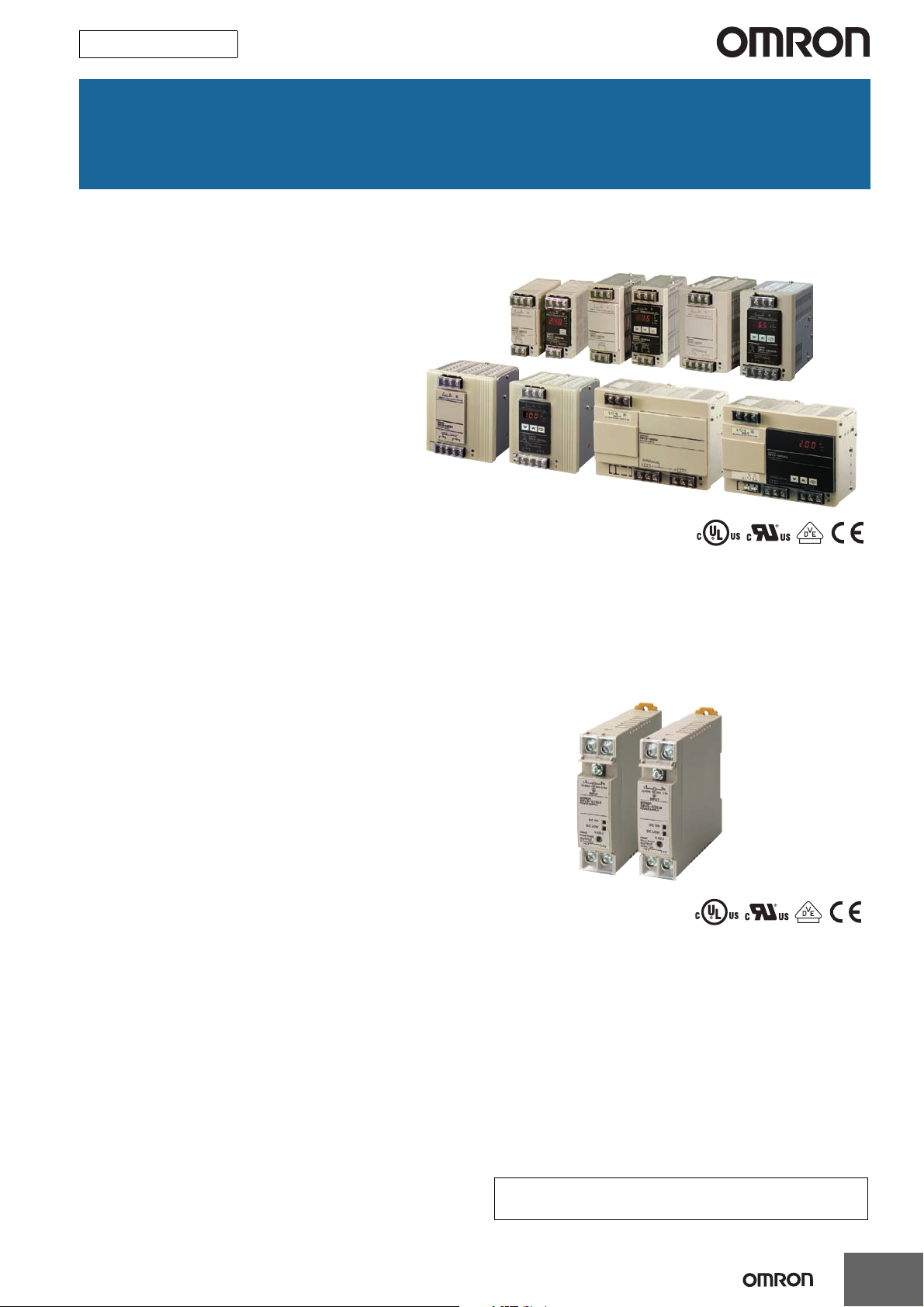
Switch Mode Power Supply
(15/30/60/90/120/180/240/480-W Models)
S8VS
60/90/120/180/240/480-W Models
New Models with Indication
Monitor and Simple Functions
for Easy System
Commissioning
• New 90-W models with indication monitor that
conform to UL Class 2 Output standards.
• New models with screwless terminal blocks
and indication monitor.
• Status displayed on 3-digit, 7-segment display.
• Safety standards:
UL 508/60950-1,
CSA C22.2 No. 107.1/60950-1
EN 50178 (= VDE 0160)
EN 60950-1 (= VDE 0805 Teil 1)
• Input conditions: DC input is also possible from 80 to 370 VDC
(Not compliant with EC Directives and other safety sta nda rd s.)
15/30-W Models
Compact, Thin Power Supplies
That Mount Just About Anywhere
to Contribute to Control Panel
Downsizing
• Compact and thin: 22.5 × 85 × 96.5 mm (W × H × D).
• Three mounting directions
(standard, horizontal, facing horizontal).
• Mounting directly to the panel is possible.
• Safety standards:
UL 508/60950-1,
CSA C22.2 No.107.1/60950-1,
EN 50178 (= VDE 0160),
EN 60950-1 (= VDE 0805 Teil 1)
• Input conditions: DC input is also possible from 80 to 370 VDC
(Not compliant with EC Directives and other safety sta nda rd s.)
Features Common to All Models
• Mount to DIN Rail.
• Complies with SEMI F47-0706 (200-VAC input).
• RoHS-compliant.
Refer to Safety Precautions for All P ow er Supplies and Safety
!
Precautions on page 32.
1
Page 2

S8VS
Model Number Structure
Model Number Legend
Note: Not all combinations are possible. Refer to List of Models in Ordering Information, below.
S8VS- @@@@@@@@-@
1234 5 6
1. Power Ratings
015: 15 W
030: 30 W
060: 60 W
090: 90 W
120: 120 W
180: 180 W
240: 240 W
480: 480 W
2. Output voltage
05: 5 V
12: 12 V
24: 24 V
3. Indication monitor
None: Without indication monitor (standard model)
A: With indication monitor (maintenance forecast monitor)
B: With indication monitor (total run time monitor)
BE: With indication monitor but without alarm output (total run
time monitor)
Note:
Estimates can be provided for coatings and other specifications that are not given in the datasheet. Ask your OMRON representative for details.
4. Alarm output
None: Sinking (Emitter COM) *
P: Sourcing (Collector COM)
Note: No alarm output possible with 60-W models.
* Both sinking and sourcing outputs are available for 480-W models.
5. UL Class 2 Output Standards (UL 1310)
None: Does not conform. *
S: Conforms.
* 15-W, 30-W, and 60-W models conform to Class 2 output standards
(UL 1310).
Note: The S option is available only for 90-W models.
6. Terminal Block Form
None: Screw terminal block
F: Screwless terminal block
2
Page 3
Ordering Information
List of Models
Note: For details on normal stock models, contact your nearest OMRON representative.
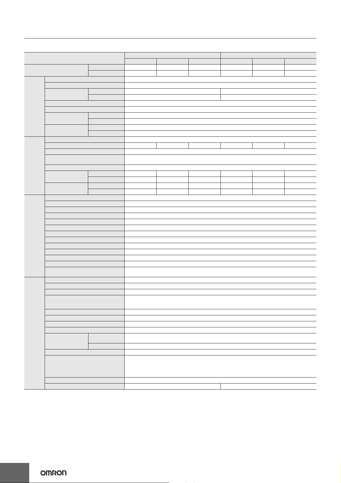
Models without Indication Monitor (Standard Models)
Power ratings Input voltage Output voltage Output current
5 V 2.0 A Yes S8VS-01505 *1
15 W
30 W
60 W
90 W 3.75 A
120 W 5 A --- S8VS-12024 S8VS-12024-F
180 W 7.5 A --- S8VS-18024 S8VS-18024-F
240 W 10 A --- S8VS-24024 S8VS-24024-F
480 W 100 to 240 VAC
*1. The output capacity of the S8VS-01505 is 10 W.
*2. The output capacity of the S8VS-03005 is 20 W.
*3. The range for compliance with EC Directives and safety standards (UL, EN, etc.) is 100 to 240 VAC (85 to 264 VAC).
100 to 240 VAC
(allowable range:
85 to 264 VAC or
80 to 370 VDC
*3)
12 V 1.2 A Yes S8VS-01512
24 V 0.65 A Yes S8VS-01524
5 V 4.0 A Yes S8VS-03005 *2
12 V 2.5 A Yes S8VS-03012
24 V 1.3 A Yes S8VS-03024
2.5 A Yes S8VS-06024 S8VS-06024-F
24 V
20 A
Peak current 30 A
(200 VAC)
UL Class 2
Output standards
--- S8VS-09024 S8VS-09024-F
Yes S8VS-09024S S8VS-09024S-F
--- S8VS-48024 S8VS-48024-F
Models with Indication Monitor (Maintenance Forecast Monitor)
Power ratings Input voltage
60 W
90 W 3.75 A
120 W 5 A
180 W 7.5 A
240 W 10 A
480 W
*1. The range for compliance with EC Directives and safety standards (UL, EN, etc.) is 100 to 240 VAC (85 to 264 VAC).
*2. In the Alarm output column, “sinking” indicates an emitter COM and “sourcing” indicates a collector COM.
100 to 240
VAC
(allowable
range: 85 to
264 VAC or 80
to 370 VDC
*1)
100 to 240
VAC
Output
voltage
24 V
Output current
2.5 A --- Yes S8VS-06024A S8VS-06024A-F
20 A
Peak current 30 A
(200 VAC)
Alarm
output *2
Sinking --- S8VS-09024A S8VS-09024A-F
Sinking Yes S8VS-09024AS S8VS-09024AS-F
Sourcing --- S8VS-09024AP S8VS-09024AP-F
Sourcing Yes S8VS-09024APS S8VS-09024APS-F
Sinking --- S8VS-12024A S8VS-12024A-F
Sourcing --- S8VS-12024AP S8VS-12024AP-F
Sinking --- S8VS-18024A S8VS-18024A-F
Sourcing --- S8VS-18024AP S8VS-18024AP-F
Sinking --- S8VS-24024A S8VS-24024A-F
Sourcing --- S8VS-24024AP S8VS-24024AP-F
Sinking/
sourcing
UL Class 2
Output standards
--- S8VS-48024A S8VS-48024A-F
Models with Indication Monitor (Total Run Time Monitor)
Power ratings Input voltage
60 W
90 W 3.75 A
100 to 240
VAC
(allowable
120 W 5 A
180 W 7.5 A
240 W 10 A
480 W
*1. The range for compliance with EC Directives and safety standards (UL, EN, etc.) is 100 to 240 VAC (85 to 264 VAC).
*2. In the Alarm output column, “sinking” indicates an emitter COM and “sourcing” indicates a collector COM.
Note: Refer to pages 24 to 25 for the options that available.
range: 85 to
264 VAC or 80
to 370 VDC)
*1
100 to 240
VAC
Output
voltage
24 V
Output current
2.5 A --- Yes S8VS-06024B S8VS-06024B-F
20 A
Peak current 30 A
(200 VAC)
Alarm
output *2
--- --- S8VS-09024BE S8VS-09024BE-F
--- Yes S8VS-09024BES S8VS-09024BES-F
Sinking --- S8VS-09024B S8VS-09024B-F
Sinking Yes S8VS-09024BS S8VS-09024BS-F
Sourcing --- S8VS-09024BP S8VS-09024BP-F
Sourcing Yes S8VS-09024BPS S8VS-09024BPS-F
--- --- S8VS-12024BE S8VS-12024BE-F
Sinking --- S8VS-12024B S8VS-12024B-F
Sourcing --- S8VS-12024BP S8VS-12024BP-F
--- --- S8VS-18024BE S8VS-18024BE-F
Sinking --- S8VS-18024B S8VS-18024B-F
Sourcing --- S8VS-18024BP S8VS-18024BP-F
--- --- S8VS-24024BE S8VS-24024BE-F
Sinking --- S8VS-24024B S8VS-24024B-F
Sourcing --- S8VS-24024BP S8VS-24024BP-F
Sinking/
sourcing
UL Class 2
Output standards
--- S8VS-48024B S8VS-48024B-F
Model number
(screw terminal block)
Model number
(screw terminal block)
Model number
(screw terminal block)
Model number
(screwless terminal block)
Model number
(screwless terminal block)
Model number
(screwless terminal block)
S8VS
---
3
Page 4
S8VS
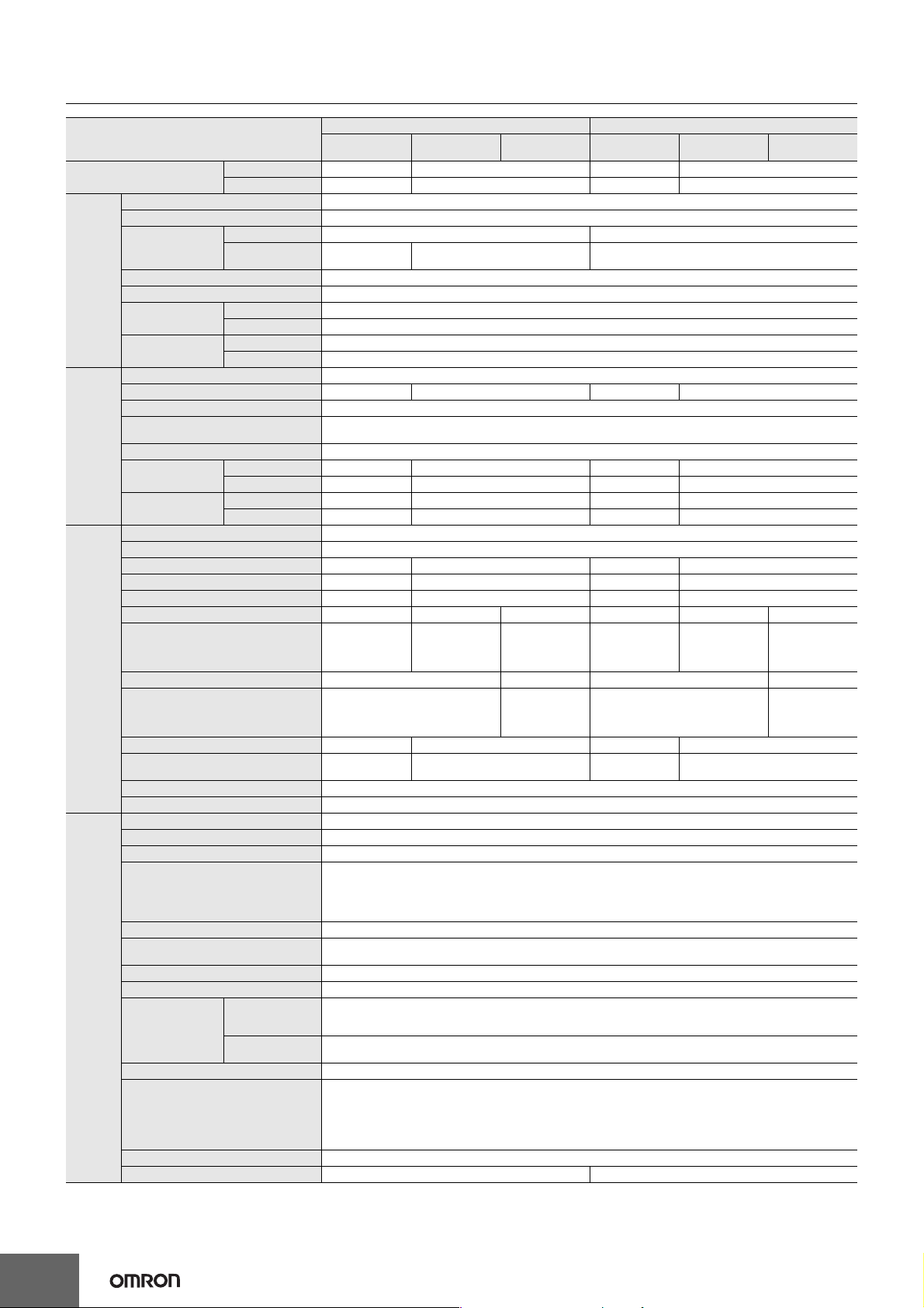
Specifications
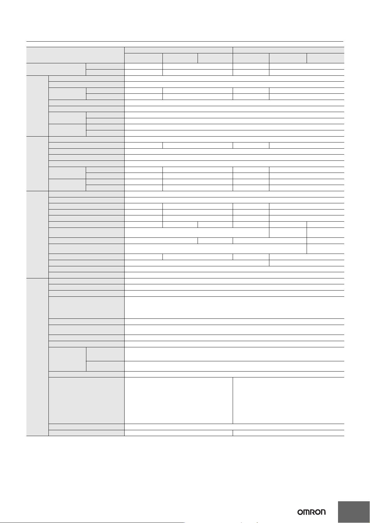
Ratings/Characteristics
Power ratings 15 W 30 W
Item Output voltage 5 V 12 V 24 V 5 V 12 V 24 V
Efficiency
Voltage *1 100 to 240 VAC (allowable range: 85 to 264 VAC, 80 to 370 VDC *5)
Frequency *1 50/60 Hz (47 to 450 Hz)
Current
Input
Output
Additional
functions
Other
Power factor --Harmonic current regulation Conforms to EN61000-3-2
Leakage current
Inrush current *2
Voltage adjustment range *3 −10% to 15% (with V.ADJ)
Ripple noise voltage (at rated I/O) 60 mV max. 70 mV max. 60 mV max. 60 mV max. 90 mV max. 150 mV max.
Input variation influence 0.5% max. (at 85- to 264-VAC input, 100% load)
Load variation influence
(rated input voltage)
Temperature variation influence 0.05%/°C max.
Startup time
(at rated I/O) *2
Output hold time
(at rated I/O) *2
Overload protection *2 The range for compliance with EC Directives and safety standards (UL, EN, etc.) is 100 to 240 VAC (85 to 264 VAC).
Overvoltage protection *2 Yes *4
Output voltage indication No
Output current indication No
Peak-hold current indication No
Maintenance forecast monitor indication No
Maintenance forecast monitor output No
Total run time monitor indication No
Total run time monitor output No
Undervoltage alarm indication Yes (color: red)
Undervoltage alarm output No
Parallel operation No
Series operation
Operating ambient temperature Refer to the derating curve in Engineering Data. (with no icing or condensation)
Storage temperature −25 to 65°C
Operating ambient humidity 25% to 85% (Storage humidity: 25% to 90%)
Dielectric strength
Insulation resistance 100 MΩ min. (between all outputs and all inputs/ PE terminals) at 500 VDC
Vibration resistance 10 to 55 Hz, 0.375-mm single amplitude for 2 h each in X, Y, and Z directions
Shock resistance 150 m/s2, 3 times each in ±X, ±Y, and ±Z directions
Output indicator Yes (color: green)
EMI
EMS Conforms to EN61204-3 high severity levels
Approved standards
SEMI F47-0706 (With 200-VAC input)
Weight 160 g max. 180 g max.
*1. Do not use an inverter output for the Power Supply. Inverters with an output frequency of 50/60 Hz are available, but the rise in the internal
temperature of the Power Supply may result in ignition or burning.
*2. For a cold start at 25°C. Refer to Engineering Data on page 18 for details.
*3. If the output voltage adjuster (V. ADJ) is turned, the voltage will increase by more than +15% of the voltage adjustment range. When adjusting
the output voltage, confirm the actual output voltage from the Power Supply and be sure that the load is not damaged.
*4. To reset the protection, turn OFF the input power for three minutes or longer and then turn it back ON.
*5. The range for compliance with EC Directives and safety standards (UL, EN, etc.) is 100 to 240 VAC (85 to 264 VAC).
With 100-VAC input 74% typical 79% typical 83% typical 74% typical 81% typical 85% typical
With 200-VAC input 73% typical 78% typical 80% typical 74% typical 80% typical 86% typical
With 100-VAC input 0.45 A max., 0.34 A typical 0.9 A max., 0.66 A typical
With 200-VAC input 0.25 A max., 0.22 A typical 0.6 A max., 0.4 A typical
With 100-VAC input 0.5 mA max.
With 200-VAC input 1.0 mA max.
With 100-VAC input 17.5 A max., 14 A typical
With 200-VAC input 35 A max., 28 A typical
2.0% max. (5 V), 1.5% max. (12 V, 24 V), (with rated input, 0 to 100% load)
With 100-VAC input 580 ms typical 530 ms typical 600 ms typical 500 ms typical 560 ms typical 560 ms typical
With 200-VAC input 340 ms typical 360 ms typical 400 ms typical 360 ms typical 380 ms typical 400 ms typical
With 100-VAC input 39 ms typical 27 ms typical 28 ms typical 31 ms typical 22 ms typical 31 ms typical
With 200-VAC input 187 ms typical 134 ms typical 134 ms typical 174 ms typical 123 ms typical 140 ms typical
Models with 24-V output: Possible for up to 2 Power Supplies (with external diode)
Models with 5- or 12-V output: Not possible
3.0 kVAC for 1 min. (between all inputs and outputs; detection current: 20 mA)
2.0 kVAC for 1 min. (between all inputs and PE terminals; detect ion current: 20 mA)
1.0 kVAC for 1 min. (between all outputs and PE terminals; detection current: 20 mA)
Conducted
Emissions
Radiated Emissions Conforms to EN61204-3 EN55011 Class B
Conforms to EN61204-3 EN55011 Class B and based on FCC Class A
UL Listed: UL508 (Listing, Class2 Output: Per 1310)
UL UR: UL60950-1 (Recognition)
cUL: CSA C22.2 No.107.1 (Class2 Output: Per CSA C22.2 No.223)
cUR: CSA C22.2 No.60950-1
EN/VDE: EN50178 (=VDE0160), EN60950-1 (=VDE0805 Teil1)
4
Page 5
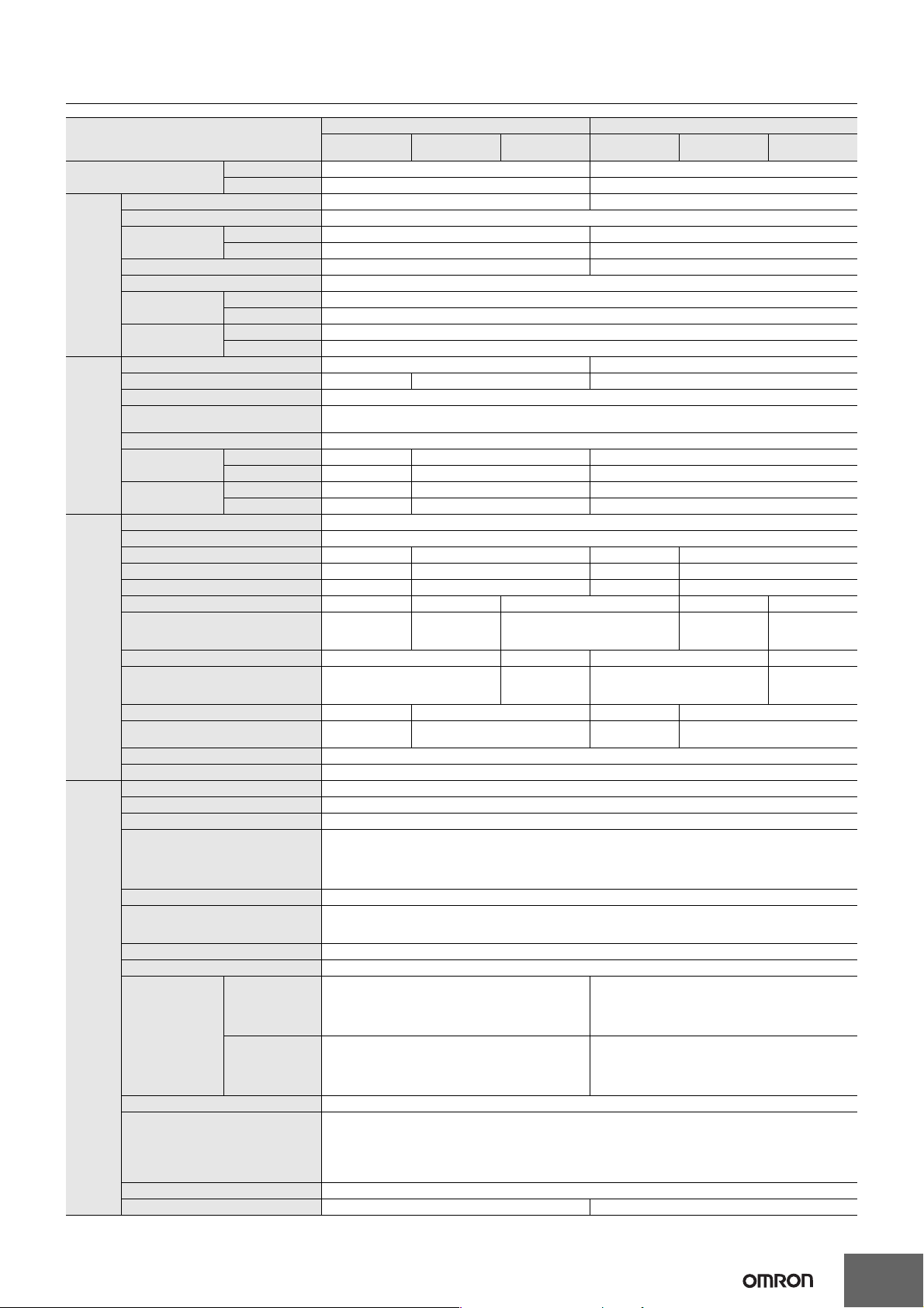
S8VS
Power ratings 60 W 90 W
Item Type Standard
Efficiency
Voltage *1 100 to 240 VAC (allowable range: 85 to 264 VAC or 80 to 370 VDC *11)
Frequency *1 50/60 Hz (47 to 450 Hz)
Current
Input
Output
Additional
functions
Other
*1. Do not use an inverter output for the Power Supply. Inverters with an output frequency of 50/60 Hz are available, but the rise in the internal temperature of the Power Supply may result in
*2. For a cold start at 25°C. Refer to Engineering Data on page 18 for details.
*3. If the output voltage adjuster (V. ADJ) is turned, the voltage will increase by more than +15% of the voltage adjustment range (by more than +10% for 240-W models w ith indi cation m onitor) .
*4. To reset the protection, turn OFF the input power for three minutes or longer and then turn it back ON.
*5. Displayed on 7-segment LED. (character height: 8 mm)
*6. Resolution of output voltage indication: 0.1 V, Precision of output voltage indication: ±2% (percentage of output voltage value, ±1 digit)
*7. Resolution of output current indication: 0.1 A; Precision of output current indication: ±5% F.S. ±1 digit max. (specified by rated output voltage)
*8. Resolution of peak-hold current indication: 0.1 A; Precision of peak-hold current indication: ±5% F.S. ±1 digit max. (specified by rated output voltage);
*9. A Type and B Type: Sinking, AP Type and BP Type: Sou r cing, BE Type: No alarm output.
*10. S8VS-06024A, S8VS-09024A/AP, S8VS-12024A/AP, S8VS-18024A/AP, and S8VS-24024A/AP only
*11. The range for compliance with EC Directives and safety standards (UL, EN, etc.) is 100 to 240 VAC (85 to 264 VAC).
Power factor --Harmonic current regulation Conforms to EN61000-3-2
Leakage current
Inrush current *2
Voltage adjustment range *3 −10% to 15% (with V. ADJ) (The voltage cannot be adjusted for the S8VS-09024@@@S-@.)
Ripple noise voltage (at rated I/O) 70 mV max. 90 mV max. 250 mV max. 150 mV max.
Input variation influence 0.5% max. (at 85- to 264-VAC input, 100% load)
Load variation influence (rated input voltage)
Temperature variation influence 0.05%/°C max.
Startup time
(at rated I/O) *2
Output hold time
(at rated I/O) *2
Overload protection *2
Overvoltage protection *2, *4 Yes
Output voltage indication *5 No Yes (selectable) *6 No Yes (selectable) *6
Output current indication *5 No Yes (selectable) *7 No Yes (selectable) *7
Peak-hold current indication *5 No Yes (selectable) *8 No Yes (selectable) *8
Maintenance forecast monitor indication *5
Maintenance forecast monitor output No
Total run time monitor indication *5 No Yes (selectable) No Yes (selectable)
Total run time monitor output *5 No
Undervoltage alarm indication *5 No Yes (selectable) No Yes (selectable)
Undervoltage alarm output terminals No
Parallel operation No
Series operation Yes for up to 2 Power Supplies (with external diode)
Operating ambient temperature Refer to the derating curve in . (with no icing or condensation)
Storage temperature −25 to 65°C
Operating ambient humidity 25% to 85% (Storage humidity: 25% to 90%)
Dielectric strength
Insulation resistance 100 MΩ min. (between all outputs/ alarm outputs and all inputs/ PE terminals) at 500 VDC
Vibration resistance
Shock resistance 150 m/s2, 3 times each in ±X, ±Y, and ±Z directions
Output indicator Yes (color: green)
EMI
EMS Conforms to EN61204-3 high severity levels
Approved standards *11
SEMI *11 F47-0706 (With 200-VAC input)
Weight 330 g max. 490 g max.
ignition or burning.
When adjusting the output voltage, confirm the actual output voltage from the Power Supply and be sure that the load is not damaged.
Signal width required for peak-hold current: 20 ms
With 100-VAC input 84% typical 83% typical 8 3% typical 83% typical
With 200-VAC input 83% typical 85% typical 8 4% typical 85% typical
With 100-VAC input
With 200-VAC input
With 100-VAC input 0.5 mA max.
With 200-VAC input 1.0 mA max.
With 100-VAC input 17.5 A max., 14 A typical
With 200-VAC input 35 A max., 28 A typical
With 100-VAC input 620 ms typical 460 ms typical 460 ms typical 660 ms typical
With 200-VAC input 400 ms typical 290 ms typical 300 ms typical 420 ms typical
With 100-VAC input 34 ms typical 33 ms typical 28 ms typical 28 ms typical
With 200-VAC input 158 ms typical 154 ms typical 132 ms typical 136 ms typical
Conducted
Emissions
Radiated
Emissions
1.7 A max., 1.3 A typical
1.0 A max., 0.68 A typical
1.5% max. (with rated input, 0 to 100% load)
105% to 160% of rated load current (101% to 110% of rated load current for the S8VS-09024
No Yes (selectable) No No Yes (selectable) No
3.0 kVAC for 1 min. (between all inputs and outputs/ alarm outputs; detection current: 20 mA)
2.0 kVAC for 1 min. (between all inputs and PE terminals; detection current: 20 mA)
1.0 kVAC for 1 min. (between all outputs/ alarm outputs and PE terminals; detection current for standard models: 30 mA, detection
current for models with indication monitor: 20mA)
500 VAC for 1 min. (between all ou tputs and alarm outputs; detection current: 20 mA)
10 to 55 Hz, 0.375-mm single amplitude for 2 h each in X, Y, and Z d irections
10 to 150 Hz, 0.35-mm single amplitude (5 G max.) for 80 min each in X, Y, and Z directions
Models with indication monitor: Conforms to EN61204-3 EN55011 Class A and based on FCC Class A, Conforms to EN61204-3
EN55011 Class B *11
Standard models: Conforms to EN61204-3 EN55011 Group 1 Class B and based on FCC Class A
Models with indication monitor: Conforms to EN61204-3 EN55011 Class A, Conforms to EN61204-3 EN55011 Class B *11
Standard models: Conforms to EN61204-3 EN55011 Group 1 Class B
UL: UL 508 (Listing; Class 2 Output: Per UL1310), UL UR: UL
60950-1 (Recognition),
cUL: CSA C22.2 No.107.1 (Class 2 Output: Per CSA C22.2 No.
223),
cUR: CSA C22.2 No.60950-1,
EN/VDE: EN 50178 (= VDE 0160), EN 60950-1
(= VDE 0805 Teil 1)
KOSHA S Mark *10
Maintenance
forecast monitor
1.7 A max., 1.3 A typical
1.0 A max., 0.78 A typical
Total run time
monitor
Standard
2.3 A max., 1.9 A typical
1.4 A max., 1.0 A typical
@@@S-@
UL: UL 508 (Listing)
UL Listed (S8VS-09024@@@S-@ only.): UL 508 (Listing, Class 2
Output: Per UL1310),
UL UR: UL 60950-1 (Recognition),
cUL: CSA C22.2 No.107.1,
cUL (S8VS-09024-@@@S-@ only): CSA C22.2 N o.107.1 (Cla ss 2
Output: Per CSA C22.2 No. 223),
cUR: CSA C22.2 No.60950-1,
EN/VDE: EN 50178 (= VDE 0160),
EN 60950-1 (= VDE 0805 Teil 1)
KOSHA S Mark *10
Maintenance
forecast monitor
2.3 A max., 1.9 A typical
1.4 A max., 1.2 A typical
), inverted L voltage drop, intermittent, automatic reset
Yes (transistor output),
30 VDC max., 50 mA max. *9
Yes (transistor output), 30 VDC max., 50 mA max. *9
Total run time
monitor
No
Yes (transistor output),
30 VDC max., 50 mA max. *9
5
Page 6
S8VS
Power ratings 120 W 180 W
Item Type Standard
Efficiency
Voltage *1 100 t o 240 VAC (allowable range: 85 to 264 VAC or 80 to 370 VDC *11)
Frequency *1 50/60 Hz (47 to 63 Hz)
Current
Input
Output
Additional
functions
Other
Power factor 0.9 min.
Harmonic current regulation Conforms to EN61000-3-2
Leakage current
Inrush current *2
Voltage adjustment range *3 −10% to 15% (with V.ADJ)
Ripple noise voltage (at rated I/O) 60 mV max. 130 mV max. 50 mV max. 180 mV max.
Input variation influence 0.5% max. (at 85- to 264-VAC input, 100% load)
Load variation influence
(rated input voltage)
Temperature variation influence 0.05%/°C max.
Startup time
(at rated I/O) *2
Output hold time
(at rated I/O) *2
Overload protection *2 105% to 160% of rated load current, inverted L voltage drop, automatic reset
Overvoltage protection *2, *4 Yes
Output voltage indication *5 No Yes (selectable) *6 No Yes (selectable) *6
Output current indication *5 No Yes (selectable) *7 No Yes (selectable) *7
Peak-hold current indication *5 No Yes (selectable) *8 No Yes (selectable) *8
Maintenance forecast monitor indication *5 No Yes (selectable) No No Yes (selectable) No
Maintenance forecast monitor output No
Total run time monitor indication *5 No Yes (selectable) No Yes (selectable)
Total run time monitor output *5 No
Undervoltage alarm indication *5 No Yes (selectable) No Yes (selectable)
Undervoltage alarm output terminals No
Parallel operation No
Series operation Yes for up to 2 Power Supplies (with external diode)
Operating ambient temperature Refer to the derating curve in . (with no icing or condensation)
Storage temperature −25 to 65°C
Operating ambient humidity 25% to 85% (Storage humidity: 25% to 90%)
Dielectric strength
Insulation resistance 100 MΩ min. (between all outputs/ alarm outputs and all inputs/ PE terminals) at 500 VDC
Vibration resistance
Shock resistance 150 m/s2, 3 times each in ±X, ±Y, and ±Z directions
Output indicator Yes (color: green)
EMI
EMS Conforms to EN61204-3 high severity levels
Approved standards *11
SEMI *11 F47-0706 (200-VAC input)
Weight 550 g max. 850 g max.
Note: Refer to page 5 for notes 1 to 11.
With 100-VAC input 84% typical 8 3% typi cal 85% typical 85% typical
With 200-VAC input 87% typical 8 5% typi cal 88% typical 87% typical
With 100-VAC input 1.9 A max., 1.5 A typical 2.9 A max., 2.2 A typical
With 200-VAC input
With 100-VAC input 0.5 mA max.
With 200-VAC input 1.0 mA max.
With 100-VAC input 17.5 A max., 14 A typical
With 200-VAC input 35 A max., 28 A typical
With 100-VAC input 550 ms typical 650 ms typical 570 ms typical 580 ms typical
With 200-VAC input 400 ms typical 520 ms typical 470 ms typical 490 ms typical
With 100-VAC input 52 ms typical 56 ms typical 58 ms typical 70 ms typical
With 200-VAC input 54 ms typical 56 ms typical 62 ms typical 70 ms typical
Conducted
Emissions
Radiated Emissions
1.1 A max.,
0.71 A typical
1.5% max. (with rated input, 0 to 100% load )
3.0 kVAC for 1 min. (between all inputs and outputs/ alarm outputs; detection current: 20 mA)
2.0 kVAC for 1 min. (between all inputs and PE terminals; detection current: 20 mA)
1.0 kVAC for 1 min. (between all outputs/ al arm outputs and PE terminals; de tection current f or standard model s: 30mA, detection
current for models with indication monitor: 20 mA
500 VAC for 1 min. (between all outputs and alarm outputs; detection current: 20 mA)
10 to 55 Hz, 0.375-mm single amplitude for 2 h each in X, Y, and Z directions
10 to 150 Hz, 0.35-mm single amplitude (5 G max.) for 80 min each in X, Y, and Z directions
Models with indication monitor: Confo rms to EN61 204-3 E N550 11 Cla ss A and b ased on FC C Class A , Con forms to E N612 04-3
EN55011 Class B *11
Standard models: Conforms to EN61204-3 EN55011 Group 1 Clas s B and based on FCC Class A
Models with indication monito r: Conforms to EN61204-3 EN55011 Class A, Conforms to EN61204- 3 EN55011 Class B *11
Standard models: Conforms to EN61204-3 EN55011 Group 1 Class B
UL Listed: UL 508 (Listing),
UL UR: UL 60950-1 (Recognition),
cUL: CSA C22.2 No. 107.1,
cUR: CSA C22.2 No. 60950-1,
EN/VDE: EN 50178 (= VDE 0160), EN 60950-1 (= VDE 0805 Teil 1)
KOSHA S Mark *10
Maintenance
forecast monitor
1.1 A max., 0.72 A typical 1.6 A max., 1.1 A typical
Yes (transistor
output), 30 VDC
max., 50 mA max.
*9
Yes (transistor output), 30 VDC max.,
50 mA max. *9
Total run time
monitor
No No
Yes (transistor
output), 30 VDC
max., 50 mA max.
*9
Standard
No
No
Maintenance
forecast monitor
Yes (transistor
output), 30 VDC
max., 50 mA max.
*9
Yes (transistor output), 30 VDC max.,
50 mA max. *9
Total run time
monitor
No
Yes (transistor
output), 30 VDC
max., 50 mA max.
*9
6
Page 7
Power ratings 240 W 480 W
Item Type Standard
Efficiency
Input
Output
Additional
functions
Other
Voltage *1
Frequency *1 50/60 Hz (47 to 63 Hz)
Current
Power factor 0.9 min. 0.95 min.
Harmonic current regulation Conforms to EN61000-3-2
Leakage current
Inrush current *2
Voltage adjustment range *3 −10% to 15% (with V.ADJ) −10% to 15% (with V.ADJ)
Ripple noise voltage (at rated I/O) 140 mV max. 160 mV max. 310 mV max.
Input variation influence 0.5% max. (at 85- to 264-VAC input, 100% load)
Load variation influence
(rated input voltage)
Temperature variation influence 0.05%/°C max.
Startup time
(at rated I/O) *2
Output hold time
(at rated I/O) *2
Overload protection *2 105% to 160% of rated load current, inverted L voltage drop, automatic reset
Overvoltage protection *2, *4 Yes
Output voltage indication *5 No Yes (selectable) *6 No Yes (selectable) *6
Output current indication *5 No Yes (selectable) *7 No Yes (selectable) *7
Peak-hold current indication *5 No Yes (selectable) *8 No Yes (selectable) *8
Maintenance forecast monitor indication *5 No Yes (selectable) No Yes (selectable) No
Maintenance forecast monitor output No
Total run time monitor indication *5 No Yes (selectable) No Yes (selectable)
Total run time monitor output *5 No
Undervoltage alarm indication *5 No Yes (selectable) No Yes (selectable)
Undervoltage alarm output terminals No
Parallel operation No
Series operation Yes for up to 2 Power Supplies (with external diode)
Operating ambient temperature Refer to the derating curve in . (with no icing or condensation)
Storage temperature −25 to 65°C
Operating ambient humidity 25% to 85% (Storage humidity: 25% to 90%)
Dielectric strength
Insulation resistance 100 MΩ min. (between all outputs/ alarm outputs and all inputs/ PE terminals) at 500 VDC
Vibration resistance
Shock resistance 150 m/s2, 3 times each in ±X, ±Y, and ±Z directions
Output indicator Yes (color: green)
EMI
EMS Conforms to EN61204-3 high severity levels
Approved standards *11
SEMI *11 F47-0706 (200-VAC input)
Weight 1,150 g max. 1,700 g max.
With 100-VAC input 85% typical 85% typical
With 200-VAC input 88% typical 89% typical
100 to 240 VAC (allowable range: 85 to 264 VAC or 80 to 370 VDC *11)
With 100-VAC input 3.8 A max., 2.9 A typical 7.4 A max., 5.8 A typical
With 200-VAC input 2.0 A max., 1.5 A typical 3.9 A max., 2.8 A typical
With 100-VAC input 0.5 mA max.
With 200-VAC input 1.0 mA max.
With 100-VAC input 17.5 A max., 14 A typical
With 200-VAC input 35 A max., 28 A typical
1.5% max. (with rated input, 0 to 100% load )
With 100-VAC input 540 ms typical 510 ms typical 460 ms typical
With 200-VAC input 230 ms typical 510 ms typical 340 ms typical
With 100-VAC input 64 ms typical 46 ms typical 37 ms typical
With 200-VAC input 64 ms typical 46 ms typical 41 ms typical
3.0 kVAC for 1 min. (between all inputs and outputs/alarm outputs; detection current: 20 mA)
2.0 kVAC for 1 min. (between all inputs and PE terminals; detection current: 20 mA)
1.0 kVAC for 1 min. (between all outputs/ alarm outputs and PE terminals; detection current for standard 240-W and 480-W
models: 30 mA, detection current for 240-W models with indication monitor: 20 mA)
500 VAC for 1 min. (between all outputs and alarm outputs; detection current: 20 mA)
10 to 55 Hz, 0.375-mm single amplitude for 2 h each in X, Y, and Z directions
10 to 150 Hz, 0.35-mm single amplitude (5 G max.) for 80 min each in X, Y, and Z directions: 240 W
10 to 150 Hz, 0.35-mm single amplitude (3 G max.) for 80 min each in X, Y, and Z directions: 480 W
Models with indication monito r: Conforms to EN61204-3
Conducted
Emissions
Radiated Emissions
EN55011 Class A and based on FCC Class A, Conforms to
EN61204-3 EN55011 Class B *11
Standard models: Conforms to EN61204-3 EN55011 Group 1
Class B and based on FCC Class A
Models with indication monito r: Conforms to EN61204-3
EN55011 Class A, Conforms to EN61204-3 EN55011 Class B
*11
Standard models: Conforms to EN61204-3 EN55011 Group 1
Class B
UL Listed: UL 508 (Listing),
UL UR: UL 60950-1 (Recognition),
cUL: CSA C22.2 No.107.1,
cUR: CSA C22.2 No. 60950-1,
EN/VDE: EN 50178 (=VDE 0160), EN 60950-1 (=VDE 0805 Teil 1)
KOSHA S Mark *10
Note: Refer to page 5 for notes 1 to 11.
Maintenance
forecast monitor
Yes (transistor output),
30 VDC max., 50 mA
max. *9
Yes (transistor output), 30 VDC max.,
50 mA max. *9
Total run time
monitor
No
Yes (transistor output),
30 VDC max., 50 mA
max. *9
S8VS
Standard
100 to 240 VAC (allowable range: 85 to 264 VAC)
No
No
Conforms to EN61204-3 EN55011 Class A and based on FCC
Class A
Conforms to EN61204-3 EN55011 Class B *11
Conforms to EN61204-3 EN55011 Class A
Conforms to EN61204-3 EN55011 Class B *11
Maintenance
forecast monitor
Yes (transistor
output), 30 VDC
max., 50 mA max.
Yes (transistor output), 30 VDC max.,
50 mA max. *9
Total run time
monitor
No
Yes (transistor output),
30 VDC max., 50 mA
max. *9
7
Page 8
S8VS
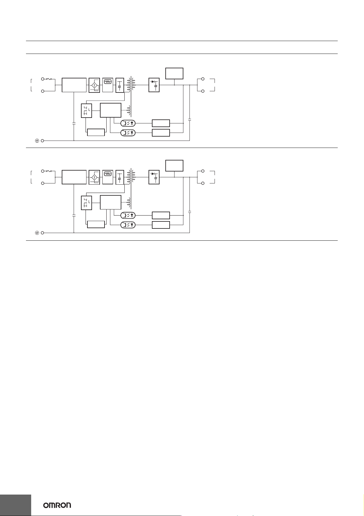
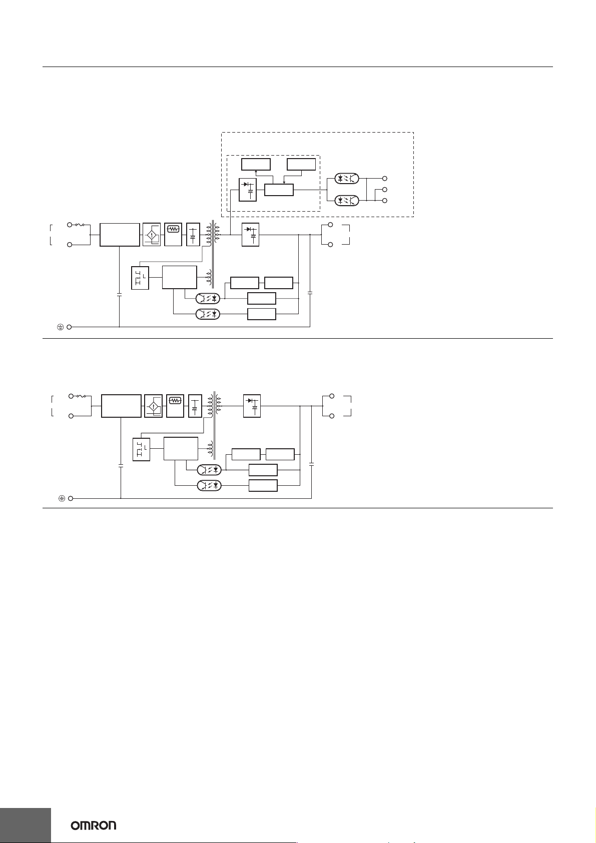
Connections
Block Diagrams
S8VS-015@@ (15 W)
Fuse:
3.15 A
AC (L)
INPUT
AC (N)
S8VS-030@@ (30 W)
Fuse:
4.0 A
AC (L)
INPUT
AC (N)
Noise filter
Noise filter
Inrush
Rectifier
current
protection
Overcurrent
detection circuit
Inrush
Rectifier
current
protection
Overcurrent
detection circuit
Drive
control
circuit
Drive
control
circuit
Smoothing
circuit
Photocoupler
Smoothing
circuit
Photocoupler
Rectifier/
smoothing
circuit
detection circuit
Overvoltage
detection circuit
Rectifier/
smoothing
circuit
detection circuit
Overvoltage
detection circuit
Voltage
Voltage
Undervoltage
indicator
Undervoltage
indicator
+V
DC output
−V
+V
DC output
−V
8
Page 9
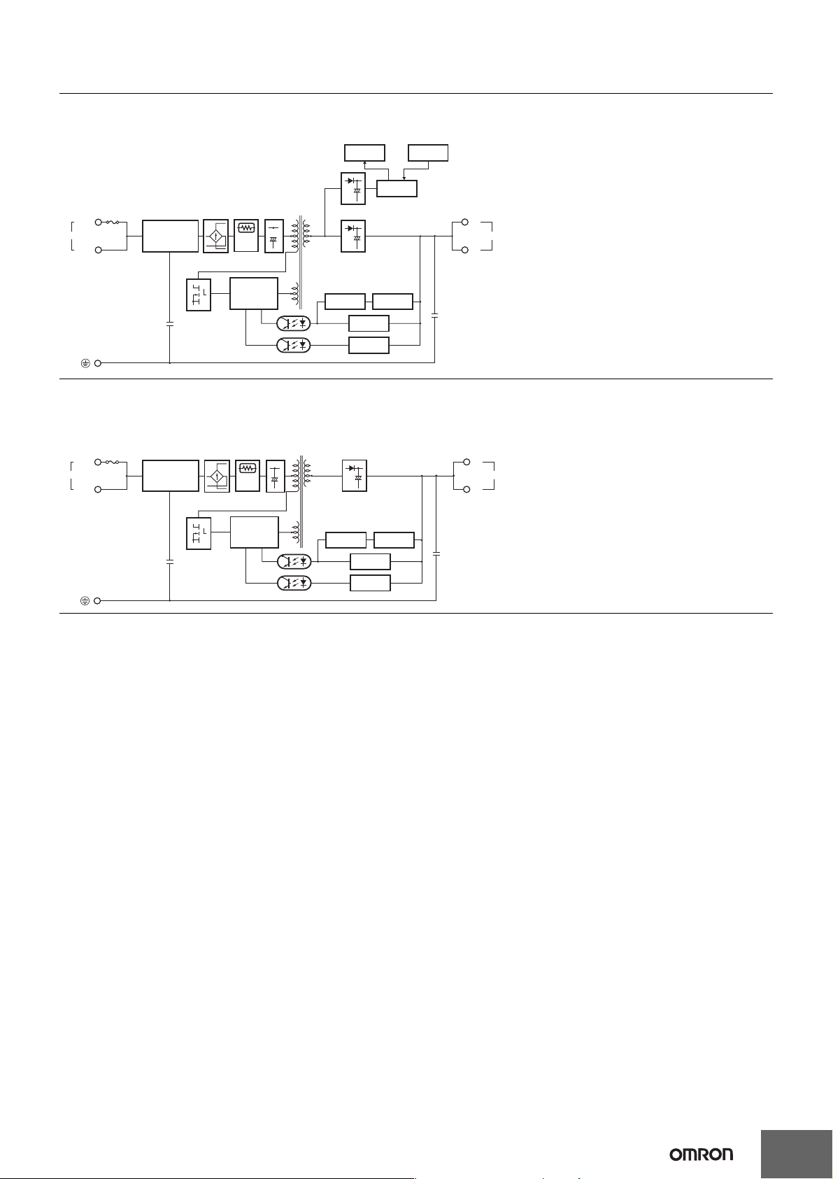
S8VS-06024A-@ (60 W)
S8VS-06024B-@ (60 W)
Fuse
6.3 A
AC (L)
INPUT
Noise filter
AC (N)
S8VS-06024-@ (60 W)
Fuse
6.3 A
AC (L)
INPUT
AC (N)
Noise filter
Rectifier
Rectifier
Inrush
Rectifier/
current
smoothing
protection
circuit
Drive control
circuit
Inrush current
protection
circuit
Drive control
circuit
circuit
Photocoupler
Smoothing
circuit
Photocoupler
Display circuit
Arithmetic
operation circuit
Rectifier/smoothing circuit
Rectifier/smoothing circuit
Overcurrent
circuit
Rectifier/smoothing circuit
Overcurrent
circuit
Current detection
circuit
Voltage
detection circuit
Overvoltage
detection circuit
Current detection
circuit
Voltage
detection circuit
Overvoltage
detection circuit
S8VS
Switch
+V
DC OUTPUT
−V
+V
DC OUTPUT
−V
9
Page 10
S8VS
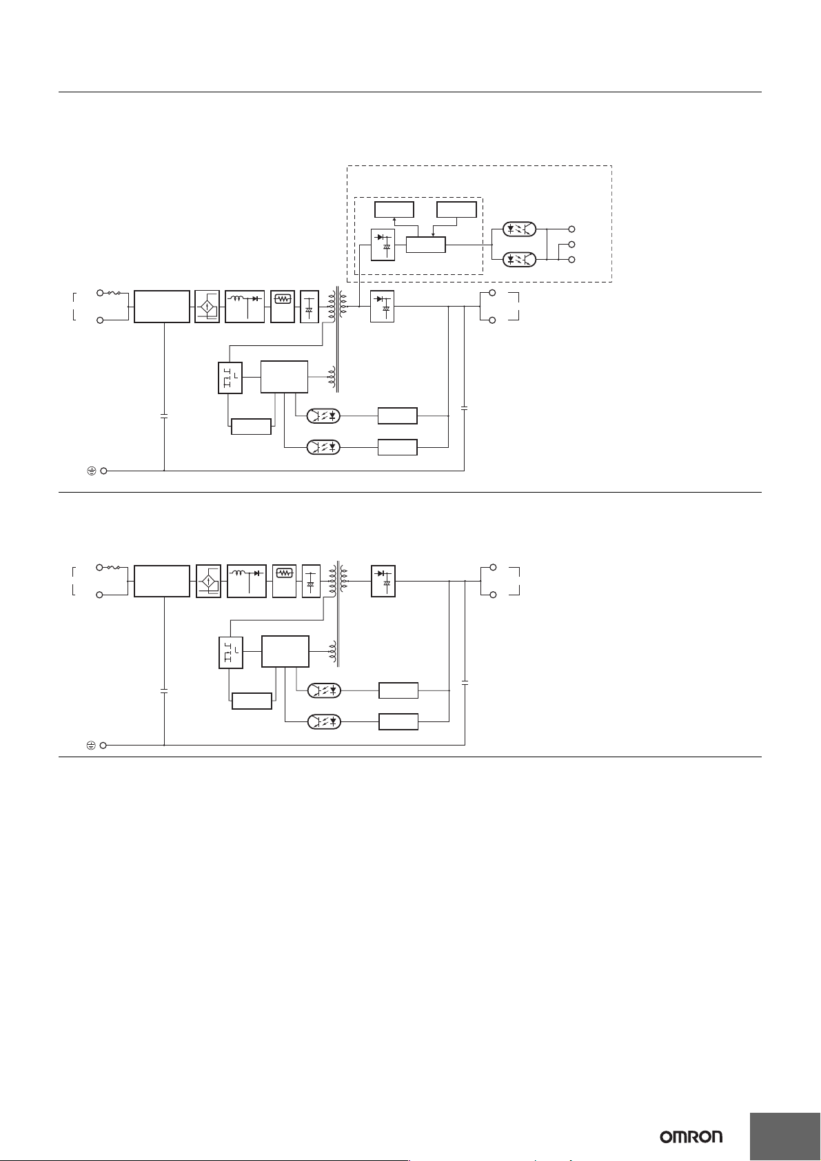
S8VS-09024A@-@ (90 W)
S8VS-09024B@-@ (90 W)
S8VS-09024BE-@ (90 W)
S8VS-09024A@S-@ (90 W)
S8VS-09024B@S-@ (90 W)
S8VS-09024BES-@ (90 W)
Fuse 8.0 A
AC (L)
INPUT
AC (N)
Noise filter
Rectifier
S8VS-09024-@ (90 W)
S8VS-09024S-@ (90 W)
Inrush current
protection
circuit
Drive control
circuit
Rectifier/
smoothing
circuit
Photocoupler
Sinking type
(S8VS-09024A-@, S8VS-09024B-@,
S8VS-09024AS-@, S8VS-09024BS-@)
Sourcing type
(S8VS-09024AP-@, S8VS-09024BP-@,
S8VS-09024APS-@, S8VS-09024BPS-@)
Type with no alarm output
(S8VS-09024BE-@, S8VS-09024BES-@)
Display circuit
Rectifier/smoothing circuit
Rectifier/smoothing circuit
Overcurrent
circuit
Voltage
detection circuit
Overvoltage
detection circuit
Arithmetic
operation circuit
Current detection
circuit
Switch
Photocoupler
+V
DC OUTPUT
−V
Alarm
DC Low
Yrs/kh
Common
AC (L)
INPUT
AC (N)
Fuse
8.0 A
Noise filter
Rectifier
Inrush current
protection
circuit
Drive control
circuit
Smoothing
circuit
Photocoupler
Rectifier/smoothing circuit
Overcurrent
circuit
Current detection
circuit
Voltage
detection circuit
Overvoltage
detection circuit
+V
DC OUTPUT
−V
10
Page 11
S8VS
S8VS-12024A@-@ (120 W)
S8VS-12024B@-@ (120 W)
S8VS-12024BE-@ (120 W)
Fuse 5.0 A
AC (L)
INPUT
AC (N)
f
Noise filter
Rectifier
S8VS-12024-@ (120 W)
Harmonic current
suppression circuit
(Power factor improvement)
Overcurrent
circuit
Inrush current
protection
circuit
Drive control
circuit
Smoothing
circuit
Photocoupler
Sinking type
(S8VS-12024A-@, S8VS-12024B-@)
Sourcing type
(S8VS-12024AP-@ S8VS-12024BP-@)
Type with no alarm output
(S8VS-12024BE-@)
Display circuit Switch
Arithmetic
operation circuit
Rectifier/smoothing circuit
Rectifier/smoothing circuit
Voltage
detection circuit
Overvoltage
detection circuit
Photocoupler
+V
DC OUTPUT
−V
Alarm
DC Low
Yrs/kh
Common
INPUT
AC (L)
AC (N)
Fuse
5.0 A
Noise filter
Rectifier
Harmonic current
suppression circuit
(Power factor improvement)
Drive control
circuit
Overcurrent
detection circuit
Inrush current
protection
circuit
Smoothing
circuit
Photocoupler
Rectifier/smoothing circuit
Voltage
detection circuit
Overvoltage
detection circuit
+V
DC OUTPUT
−V
11
Page 12
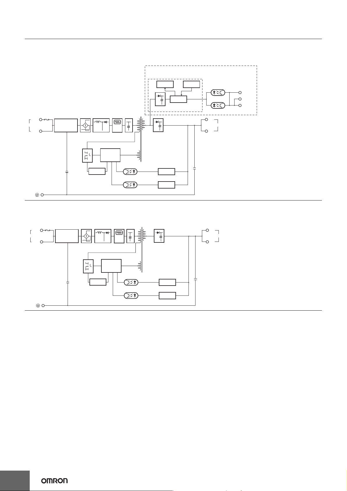
S8VS
S8VS-18024A@-@ (180 W)
S8VS-18024B@-@ (180 W)
S8VS-18024BE-@ (180 W)
Fuse 6.3 A
AC (L)
INPUT
AC (N)
Noise filter
Rectifier
S8VS-18024-@ (180 W)
Harmonic current
suppression circuit
(Power factor improvement)
Drive control
circuit
Overcurrent
detection circuit
Inrush current
protection
circuit
Photocoupler
Smoothing
circuit
Sinking type
(S8VS-18024A-@, S8VS-18024B-@)
Sourcing type
(S8VS-18024AP-@, S8VS-18024BP-@)
Type with no alarm output
(S8VS-18024BE-@)
Display circuit Switch
Arithmetic
operation circuit
Rectifier/smoothing circuit
Rectifier/smoothing circuit
Voltage
detection circuit
Overvoltage
detection circuit
Photocoupler
+V
DC OUTPUT
−V
Alarm
DC Low
Yrs/kh
Common
INPUT
AC (L)
AC (N)
Fuse
6.3 A
Noise filter
Rectifier
Harmonic current
suppression circuit
(Power factor improvement)
Drive control
circuit
Overcurrent
detection circuit
Inrush current
protection
circuit
Photocoupler
Smoothing
circuit
Rectifier/smoothing circuit
Voltage
detection circuit
Overvoltage
detection circuit
+V
DC OUTPUT
−V
12
Page 13

S8VS
S8VS-24024A@-@ (240 W)
S8VS-24024B@-@ (240 W)
S8VS-24024BE-@ (240 W)
Fuse 8.0 A
AC (L)
INPUT
AC (N)
Noise filter
Rectifier
S8VS-24024-@ (240 W)
Harmonic current
suppression circuit
(Power factor improvement)
Drive control
circuit
Overcurrent
detection circuit
Inrush current
protection
circuit
Photocoupler
Smoothing
circuit
Sinking type
(S8VS-24024A-@, S8VS-24024B-@)
Sourcing type
(S8VS-24024AP-@, S8VS-24024BP-@)
Type with no alarm output
(S8VS-24024BE-@)
Display circuit Switch
Arithmetic
operation circuit
Rectifier/smoothing circuit
Rectifier/smoothing circuit
Voltage
detection circuit
Overvoltage
detection circuit
Photocoupler
+V
+V
DC OUTPUT
−V
−V
Alarm
DC Low
Yrs/kh
Common
INPUT
AC (L)
AC (N)
Fuse
8.0 A
Noise filter
Rectifier
Harmonic current
suppression circuit
(Power factor improvement)
Drive control
circuit
Overcurrent
detection circuit
Inrush current
protection
circuit
Photocoupler
Smoothing
circuit
Rectifier/smoothing circuit
Voltage
detection circuit
Overvoltage
detection circuit
+V
DC OUTPUT
−V
13
Page 14

S8VS
S8VS-48024-@ (480 W)
S8VS-48024A-@ (480 W)
S8VS-48024B-@ (480 W)
Fuse 12A
AC (L)
INPUT
AC (N)
Noise filter
Inrush
current
protection
circuit
Rectifier
Harmonic current
suppression
(power factor
improvement)
Smoothing
circuit
Auxiliary power
supply circuit
Drive circuit
Rectifier/
smoothing
circuit
Overvoltage
detection circuit
Control
circuit
Arithmetic
operation
circuit
Rectifier/
smoothing circuit
Voltage
detection circuit
Current
detection circuit
Overcurrent
circuit
S8VS-48024A/B
+V
+V
+V
DC OUTPUT
−V
−V
−V
Alarm Output Connections
90, 120, 180, and 240 W (Sinking type)
Undervoltage
Maintenance
forecast time or
total run time
90, 120, 180, and 240 W (Sourcing type)
Undervoltage
Maintenance
forecast time or
total run time
480 W
Undervoltage
Maintenance
forecast time or
total run time
11
12
13
13
11
12
12
11
14
13
Undervoltage
Maintenance
forecast time or
total run time
Common
Common
Undervoltage
Maintenance
forecast time or
total run time
Undervoltage
Maintenance
forecast time or
total run time
Display
circuit
Switch
DC LOW
Yrs/kh
Photocoupler
14
Page 15

Construction and Nomenclature
Nomenclature
15-W, 30-W Models
S8VS-015@@/S8VS-030@@
1
No. Name Function
1 Input terminals (L), (N) Connect the input lines to these terminals. *1
2 Protective Earth terminal (PE) Connect the ground line to this terminal. *2
2
3 DC Output terminals (−V), (+V) Connect the load lines to these terminals.
4 Output indicator (DC ON: Green) Lights while a direct current (DC) output is ON.
4
5 Undervoltage indicator (DC LOW: Red) Lights when a drop is detected in the output voltage.
5
6 Output voltage adjuster (V.ADJ) Use to adjust the voltage.
6
*1. The fuse is located on the (L) side. For a DC input, connect the positive voltage to the L terminal.
*2. This is the protective earth terminal specified in the safety standards. Always ground this terminal.
3
Note: The S8VS-01505 is shown above.
S8VS
15
Page 16

S8VS
Nomenclature
60-W Models
Standard Model
S8VS-06024
1
3
Models with Indication Monitor
S8VS-06024@
2
4
5
Note: The S8VS-06024A is shown above.
90-W/120-W Models
Standard Models
S8VS-09024/S8VS-0924S/
S8VS-12024
12
3
Models with Indication Monitor
S8VS-09024@@@/
S8VS-09024@@@S/S8VS-12024@@@
4
5
Note: The S8VS-12024A is shown above.
180-W Models
Standard Model
S8VS-18024
1 2
3
Models with Indication Monitor
S8VS-18024@@@
4
5
Note: The S8VS-18024A is shown above.
240-W Models
Standard Model
S8VS-24024
12
Models with Indication Monitor
S8VS-24024@@@
No. Name Function
1
1
2
2
3
76
8
4
5
4
5
3
3
1
10
3
131211
2
76
8
9
4
5
6 Main display (Red) *4
7
8 Mode Key *4
9Up Key *5
10 Down Key *5
1
6
10
12
3
1113
2
7
8
9
4
5
11
12
13
*1. The fuse is located on the (L) side. For a DC input, connect the
*2. This is the protective earth terminal specified in the safety
12
*3. The output voltage cannot be adjusted for the
*4. S8VS-@@@24A@@/B@@/BE@ only.
*5. S8VS-@@@24A@@/B@@ only (except the S8VS-06024@).
6
10
7
8
9
*6. Both sinking and sourcing outputs are available.
*7. S8VS-@@@24A@@ only (excluding S8VS-06024A).
*8. S8VS-@@@24B@@ only (excluding S8VS-06024B).
Input terminals
(L), (N)
Protective Earth
terminal (PE)
DC Output terminals
(−V), (+V)
Output indicator
(DC ON: Green)
Output voltage
adjuster (V.ADJ)
Connect the input lines to these
terminals. *1
Connect the ground line to this
terminal. *2
Connect the load lines to these
terminals.
Lights while a direct current (DC)
output is ON.
Use to adjust the voltage. *3
Indicates the measurement or set
value.
Lights up when the output voltage is
V
indicated. Blinks during setup of
undervoltage alarm value.
Lights up during indication of output
A
current.
Lights up during indication of peak
Apk
Operation
indicator
(Orange) *4
hold current.
Lights up during indication of
maintenance forecast monitor.
Yrs
Blinks during setup of maintenance
forecast monitor setting. (S8VS@@@24A@@)
Lights up during indication of total
run time monitor. Blinks during setup
kh
of total run time monitor. (S8VS@@@24B@@)
Use the Mode Key to change the
indicated parameter or reset the
peak hold current value.
Use the Up Key to change to the
setting mode or to increase the set
value.
Use the Down Key to change to the
setting mode or to decrease the set
value.
Alarm
outputs
*5, *6
Undervoltage
output
terminal (DC
Low)
Maintenance
Forecast
output
terminal (Yrs)
*7
Total run time
output
terminal (kh)
Output when a drop is detected in
the output voltage (voltage drop =
transistor OFF).
Output when the set value for
maintenance is reached (transistor
OFF).
Output when the set value for total
run time is reached (transistor OFF).
*8
Common
terminal
Common terminal for terminals 11
and 12.
positive voltage to the L terminal.
standards. Always ground this terminal.
S8VS-09024@@@S.
4
5
3
12
1311
Note: The S8VS-24024A is shown above.
3
* The terminal arrangement is the same for models with screwless
terminal blocks and standard models.
16
4
5
Page 17

S8VS
480-W Models
Standard Model
S8VS-48024
1 2
4
5
3
Models with Indication Monitor
S8VS-48024@
1 2
6
7
9
10
16
15
13
14
12
11
Note: The illustration shows the S8VS-48024A model.
* The terminal arrangement is the same for models with screwless
terminal blocks and standard models.
8
4
5
3
No. Name Function
AC Input terminals
1
(L), (N)
Protective Earth
2
terminal (PE)
DC Output terminals
3
(−V), (+V)
Output indicator
4
(DC ON: Green)
Output voltage adjuster
5
(V.ADJ)
6 Main display (Red) *3
Connect the input lines to these
terminals. *1
Connect the ground line to this
terminal. *2
Connect the load lines to these
terminals.
Lights while a direct current (DC)
output is ON.
Use to adjust the voltage.
Indicates the measurement or set
value.
Lights up when the output voltage is
V
indicated. Blinks during setup of
undervoltage alarm value.
Lights up during indication of output
A
current.
Lights up during indication of peak
Apk
hold current.
Lights up during indication of
maintenance forecast monitor.
Yrs
Blinks during setup of maintenance
7
Operation
indicator
(Orange) *3
forecast monitor setting. (S8VS48024A)
Lights up during indication of total
run time monitor. Blinks during setup
kh
of total run time monitor. (S8VS48024B)
Use the Mode Key to change the
8 Mode Key *3
indicated parameter or reset the
peak hold current value.
Use the Up Key to change to the
9Up Key *3
setting mode or to increase the set
value.
Use the Down Key to change to the
10 Down Key *3
setting mode or to decrease the set
value.
Undervoltage
11
12
output terminal
(DC Low)
(Emitter side)
Undervoltage
output terminal
(DC Low)
Output when a drop is detected in
the output voltage (voltage drop =
transistor OFF).
(Collector side)
Maintenance
13
Alarm
outputs
*3
Forecast
output terminal
(Yrs) *4
(Emitter side)
Total run time
output terminal
(kh) *5
Output when the set value for
maintenance is reached (transistor
OFF).
Output when the set value for total
run time is reached (transistor OFF).
(Emitter side)
Maintenance
14
Forecast
output terminal
(Yrs) *4
(Collector side)
Output when the set value for
maintenance is reached (transistor
OFF).
Total run time
output terminal
(kh) *5
Output when the set value for total
run time is reached (transistor OFF).
(Collector side)
15,
NC (Not connected)
16
*1. The fuse is located on the (L) side. It is NOT user replaceable.
*2. This is the protective earth terminal specified in the safety standards.
Always ground this terminal.
*3. S8VS-48024A/B only.
*4. S8VS-48024A only.
*5. S8VS-48024B only.
17
Page 18

S8VS
Engineering Data
Derating Curve
15 W <S8VS-015@@>
120
100
Load ratio (%)
80
60
40
20
0
−20 −10 0 10 20 30 40 50 60 70 80
*1 Standard mounting
*2 Face-up mounting
*3 Horizontal mounting
Ambient temperature (°C)
30 W <S8VS-03005/S8VS-03012>
120
100
Load ratio (%)
80
60
40
1
1
60, 90, 120, 180, 240, and 480 W
120
100
Load (%)
*1
*2
*3
80
60
40
20
0
−20 −10 0 10 20 30 40 50 60 70 80
* Using side mounting bracket for right-side mounting (excluding
240-W models). UL certification conditions do not apply if the side
mounting bracket is used.
Note: 1. Internal parts may occasionally deteriorate or be damaged.
Do not use the Power Supply in areas outside the derating
curve (i.e., the area shown by shading A in the above
graph).
2. If there is a derating problem, use forced air-cooling.
3. When using a 480-W model at an input voltage of 95 VAC
or less, derate the load by at least 80%.
4. DC Inputs
*1
*2
If the input voltage is less than 100 VDC, reduce the load
given in the above derating curve by at least the following
factor.
60-W models: 0.9 max.
90-W models: 0.85 max.
120-W/180-W/240-W models: 0.8 max.
1
*
Ambient temperature (°C)
20
0
−20 −10 0 10 20 30 40 50 60 70 80
*1 Standard mounting
*2 Face-up mounting/Horizontal mounting
Ambient temperature (°C)
30 W <S8VS-03024>
120
100
Load ratio (%)
80
60
40
20
0
−20 −10 0 10 20 30 40 50 60 70 80
*1 Standard mounting
*2 Face-up mounting/Horizontal mounting
Ambient temperature (°C)
Note: 1. Internal parts may occasionally deteriorate or be damaged.
Do not use the Power Supply in areas outside the derating
curve (i.e., the area shown by shading A in the above
graph).
2. If there is a derating problem, use forced air-cooling.
3. Provide a space of at least 20 mm when using standard
mounting and horizontal mounting. If 20 mm is not available,
make sure that the space is at least 10 mm. In this case,
reduce the corresponding derating curve by 5°C.
4. DC Inputs
If the input voltage is less than 100 VDC, reduce the load
given in the above derating curve by at least the following
factor.
S8VS-03005: 0.7 max.
S8VS-03012/03024: 0.85 max.
1
*1
*2
18
Page 19

S8VS
Mounting
15 and 30 W
Standard mounting with DIN rail
Standard mounting with S82Y-VS30P
Note: The Side-mounting Bracket can be mounted from either side.
Horizontal mounting with S82Y-VS30P*
Face-up mounting with DIN rail
Face-up mounting with S82Y-VS30P
S82Y-VS30P
Side with label
Overload Protection
The load and the power supply are automatically protected from
overcurrent damage by this function.
Overload protection is activated if the output current rises above
105% of the rated current.
When the output current returns within the rated range overload
protection is automatically cleared.
15-W/30-W Models
Output voltage (V)
Intermittent
operation
0 10050
The values shown in the above diagrams are for reference only.
120-W/180-W/240-W/480-W Models
Output voltage (V)
Output current (%)
60-W/90-W Models
Output voltage (V)
Intermittent operation
050100
Output current (%)
Note: 1. Improper mounting will interfere with heat dissipation and
may occasionally result in deterioration or damage of
internal parts. Use the Product within the derating curve for
the mounting direction that is used. Do not use the Power
Supply mounted in any way not shown above.
2. Use a mounting bracket (S82Y-VS30P, sold separately)
when the Product is mounted horizontally.
3. Heat dissipation will be adversely affected. When the
Product is mounted facing horizontally, always place the
side with the label facing horizontally.
4. Use PFP-M End Plates on the top and bottom of the Power
Supply when mounting horizontally on a DIN rail.
60, 90, 120, 180, 240, and 480 W
Upper
Correct Incorrect
Standard mounting Face-up mounting
Note: Improper mounting will interfere with heat dissipation and may
occasionally result in deterioration or damage of internal parts.
It may also result in failure of the maintenance forecast monitor
function. Use the standard mounting method only.
Upper
050100
Output current (%)
The values shown in the above diagrams are for reference only.
Note: 1. Internal parts may occasionally deteriorate or be damaged
if a short-circuited or overcurrent state continues during
operation.
2. Internal parts may possibly deteriorate or be damaged if the
Power Supply is used for applications with frequent inrush
current or overloading at the load end. Do not use the Power
Supply for such applications.
Peak Output Current (S8VS-48024@ only)
The peak current must satisfy the following conditions.
Input voltage range: 200 to 240 VAC
Peak current value: 30 A max.
Peak current pulse width: 2 s max.
Cycle: 60 s min.
Note: 1. Two seconds after the peak current is reached, the peak
current limiting function operates to stop the peak current
flow.
2. It takes 60 seconds for the peak current to be able to flow
again.
3. The peak current limiting function prevents the peak current
from flowing at 100 to 120 VAC.
Peak current limit
Overcurrent
protection point
Output current
0 A
2 s
60 s min.
Peak current
condition
19
Page 20

S8VS
Overvoltage Protection
Consider the possibility of an overvoltage and design the system so
that the load will not be subjected to an excessive voltage even if the
feedback circuit in the Power Supply fails. If an excessive voltage that
is approximately 130% of the rated voltage (but approximately 110%
of the rated voltage for the S8VS-09024@@@S) or more is output, the
output voltage is shut OFF. Reset the input power by turning it OFF
for at least three minutes and then turning it back ON again.
Overvoltage protection
+30%
(approx.)
+15%
Output voltage (V)
Rated output
voltage
−10%
0 V
The values shown in the above diagram is for reference only.
Variable range
operating
Note: Do not turn ON the power again until the cause of the
overvoltage has been removed.
Inrush Current, Startup Time, Output Hold Time
AC input
voltage
Input ON
Input OFF
Undervoltage Alarm Function (Indication and
Output) (S8VS-@@@24A@@/S8VS-@@@24B@@/
S8VS-@@@24BE@ Only)
When output voltage drop is detected, an alarm (a01) and lowest
output voltage value are indicated alternately. The preset value of
detection voltage can be changed in the setting mode.
(From 18.5 to 27.5 V in 0.1-V steps. The value is fixed at 20.0 V for
the S8VS-06024A/S8VS-06024B.)
Further, an output (undervoltage output terminal (DC LOW)) to an
external device is given from the transistor to notify of the error
(excluding S8VS-06024A/S8VS-06024B/S8VS-@@@24BE@).
(Output voltage drop = OFF, i.e., no continuity at the undervoltage
output terminal (DC LOW).)
Example: Outputting an Alarm When the Voltage Output by the
S8VS-09024A@@ Drops to the Set Value (19.0 V) or Lower
In the case that the
output voltage drops
below the set value (19.0 V)
and an alarm is issued
Note: 1. Operation begins after about three seconds since the AC
AC input
Output
voltage
power is supplied.
2. The alarm is not indicated in the setting mode.
3. Press the (Mode Key (8)) after the output voltage is
restored, to reset alarm indication.
4. The undervoltage alarm function may also operate when an
interruption in AC input is not restored within 20 ms.
5. The undervoltage alarm function monitors the output
terminal voltage of the Power Supply. To check the voltage
accurately, measure the voltage at the load end.
Detection value
of Undervoltage
alarm
:
AC input
current
Output
voltage
Inrush current on input application
Startup time (1,000 ms max.)
90%
Hold time
(20 ms min.)
96.5%
Undervoltage Alarm Indication
LED (DC LOW: red) lights to warn of output voltage drop.
Detection voltage is set to approx. 80% (75 to 90%) of the rated output
voltage.
Note: This function monitors the voltage at the power supply output
terminals. To check actual voltage, measure voltage on the
load side.
Undervoltage
output
Main display Voltage indication
Operation
mode
Lowest value of
output voltage
Note: Operation begins after about three seconds since the AC
power is supplied.
20
Page 21

Dimensions
(
)
Power Supplies with Screw Terminal Blocks
Note: All units are in millimeters unless otherwise indicated.
S8VS
S8VS-015@@ (15 W)
S8VS-030@@ (30 W)
35.2
4
Note: The illustration is the S8VS-03024 model.
S8VS-06024 (60 W)
S8VS-06024A (60 W)
S8VS-06024B (60 W)
35.4
1
Note: The illustration is the S8VS-06024A model.
96.4
97.1
108.3
11.2
8
Five, M3.5 terminal
screws with square
washers
Rail stopper
Five, M4 terminal screws
with square washers
74
Rail stopper
10.4
10.2
22.5
10 7
40
4.8
(Sliding: 10 max.)
85
4.8
(Sliding: 10 max.)
95
4.5
(Sliding: 15 max.)
S8VS-09024 (90 W) /S8VS-09024S (90 W) /S8VS-12024 (120 W)
S8VS-09024A@ (90 W) /S8VS-09024A@S (90 W) /S8VS-12024A@ (120 W)
S8VS-09024B@ (90 W) /S8VS-09024B@S (90 W) /S8VS-12024B@ (120 W)
S8VS-09024BE (90 W) /S8VS-09024BES (90 W) /S8VS-12024BE (120 W)
Five, M4 terminal screws
with square washers
Screwless block (2.5-mm pitches)
35.4
110.3
1
121.2
10.9
Note: The illustration is the S8VS-12024A model.
S8VS-18024 (180 W)
S8VS-18024A@ (180 W)
S8VS-18024B@ (180 W)
116.6
8.7
S8VS-18024BE (180 W)
35.4
10 7
94
50
Rail stopper
Seven, M4 terminal screws
with square washers
94
(Sliding: 15 max.)
10 7
115
4.5
115
1
Note: The illustration is the S8VS-18024A model.
125.3
Screwless block
75
Rail stopper
2.5-mm pitches
4.5
(Sliding: 15 max.)
21
Page 22

S8VS
S8VS-24024 (240 W)
S8VS-24024A@ (240 W)
S8VS-24024B@ (240 W)
S8VS-24024BE (240 W)
35.4
1
Note: The illustration shows the S8VS-24024A model.
S8VS-48024 (480 W)
S8VS-48024A (480 W)
S8VS-48024B (480 W)
35.4
117.6
125.2
127.2
123.8
Seven, M4 terminal screws
with square washers
7.6
94
Screwless block (2.5-mm pitches)
Rail stopper
Nine, M4 terminal screws with square washers
115
93
100
7
115
10
50
7
4.5 (Sliding: 15 max.)
Rail stopper
150
115
Screwless block (2.5-mm pitches)
Rail stopper
Note: The illustration shows the S8VS-48024A model.
Power Supplies with Screwless Terminal Blocks
S8VS-06024-F (60 W)
S8VS-06024A-F (60 W)
97.1
S8VS-06024B-F (60 W)
35.4
1
107.3
Note: The illustration shows the S8VS-06024-F model.
S8VS-09024-F (90 W) /S8VS-09024S-F (90 W) /S8VS-12024-F (120 W)
S8VS-09024A@-F (90 W) /S8VS-09024A@S-F (90 W ) /S8VS-12024A@-F (120 W)
S8VS-09024B@-F (90 W) /S8VS-09024B@S-F (90 W) /S8VS-12024B@-F (120 W)
S8VS-09024BE-F (90 W) /S8VS-09024BES-F (90 W) /S8VS-12024BE-F (120 W)
110.3
10.2
10
Rail stopper
10
70
10
40
10
Rail stopper
9577.4
4.5 (Sliding: 15 max.)
4.5 (Sliding: 15 max.)
Note: The illustration shows the S8VS-12024-F model.
22
11535.4 97.3
1
120.3
Rail stopper
50
4.5 (Sliding: 15 max.)
Page 23

S8VS
S8VS-18024-F (180 W)
S8VS-18024A@-F (180 W)
S8VS-18024B@-F (180 W)
S8VS-18024BE-F (180 W)
35.4
1
Note: The illustration shows the S8VS-18024-F model.
S8VS-24024-F (240 W)
S8VS-24024A@-F (240 W)
S8VS-24024B@-F (240 W)
S8VS-24024BE-F (240 W)
35.4
1
Note: The illustration shows the S8VS-24024-F model.
116.6
124.3
117.6
124.3
7.7
97.3
6.7
97.3
Rail stopper
Rail stopper
10
115
75
100
10
10
50
4.5 (Sliding: 15 max.)
115
4.5 (Sliding: 15 max.)
Rail stopper
S8VS-48024-F (480 W)
S8VS-48024A-F (480 W)
S8VS-48024B-F (480 W)
35.4
Note: The illustration shows the S8VS-48024-F model.
127.2
122.9
96.3
Rail stopper
150
115
10
70
4.5 (Sliding: 15 max.)
Rail stopper
23
Page 24

S8VS
DIN Rail (Order Separately)
Note: All units are in millimeters unless otherwise indicated.
Mounting Rail (Material: Aluminum)
PFP-100N
PFP-50N
±
0.15
4.5
Mounting Rail (Material: Aluminum)
4.5
End Plate
M4×8 pan-
head screw
50
11.5
15 25 25
10 10
15 25 25
10 10
10
M4 spring washer
1,000 (500) *
1,000
25 25 15(5) *
PFP-100N2
25 25 15
PFP-M
10
6.2
1.8
1
1.3
4.8
1.8
35.5
35.5
7.3
±
0.3
35
* Values in parentheses are for the PFP-50N.
±
0.3
±
0.15
27
1
16
1 1.5
29.2242735
Note: If there is a possibility that the Unit will be subject to vibration or shock, use a steel DIN Rail. Otherwise, metallic filings may result from
aluminum abrasion.
Terminal Block Cover (Order Separately)
Terminal Block Cover model Applicable models and locations
S82Y-VS-C2P-S
S82Y-VS-C3P
S82Y-VS-C2P-M
S82Y-VS-C4P
S8VS-15W
S8VS-30W
S8VS-60W input side
S8VS-90W input side
S8VS-120W input side
S8VS-180W input side
S8VS-240W input side
S8VS-480W input/output side
S8VS-60W output side
S8VS-90W output side
S8VS-120W output side
S8VS-180W output side
S8VS-240W output side
24
Page 25

Mounting Brackets
Name Model
Side-mounting Bracket (for 15- and 30-W models) S82Y-VS30P
Side-mounting Bracket (for 60-, 90-, and 120-W models) S82Y-VS10S
Side-mounting Bracket (for 180-W models) S82Y-VS15S
Side-mounting Bracket (for 240-W models) S82Y-VS20S
Front-mounting Bracket (for 60-, 90-, 120-, 180-, and 240-W models) * S82Y-VS10F
Note: Brackets cannot be used for 480-W models.
* Two required to mount a 240-W model.
Type Model Dimensions Appearance
Side-mounting Bracket
(For 15-, 30-W models)
S82Y-VS30P
85.4
0.5
109.4
28
34
3.5
15
93.6
t = 0.8
±0.1
4.5 dia.
7.1
±0.1
3.5 dia.
15
S8VS
15
22.5
Left-side mounting Right-side mounting
Side-mounting Bracket
(For 60-, 90-, 120-W
models)
Side-mounting Bracket
(For 180-W models)
Side-mounting Bracket
(For 240-W models)
Front-mounting Bracket
(For 60-, 90-, 120-, 180-,
and 240-W models)
S82Y-VS10S
S82Y-VS15S
S82Y-VS20S
S82Y-VS10F
47.5
t = 2.0
±0.1
55
55±0.1
78
60
±0.1
13
Left-side mounting
60±0.1
*Right-side mounting also possible.
±0.1
±0.1
60
±0.1
13
55
78
(For 60-, 90-, 120-,
180-W types)
35
25
7.3
10
Left-side mounting
*Right-side mounting also possible.
(For 240-W type)
*Use two S82Y-VS10F
brackets for the 240-W type.
80
35
64
t = 2.0
4.5 dia.±0.1
80
89
4.5 dia.
80
60
114
t = 2.0
41
4.5 dia.±0.1
±0.1
35
40
50
25
Page 26

S8VS
Display and Alarm Output Functions and Operating Procedures
S8VS-@@@24A@@ models (with display monitor) can display the output voltage, output current, peak hold current, or maintenance forecast
monitor time. S8VS-@@@24B@@/S8VS-@@@24BE@ models (with display monitor) can display the output voltage, output current, peak hold
current, or total run time.
Mode Change
Power-ON
Model indication
Operation mode
Press and hold
Up key
U or Down Key D
for three seconds or more.
Setting mode
Note: No setting mode is provided for the S8VS-06024@.
Operation Mode
Various states of the Power Supply are indicated.
Models with Maintenance Forecast Monitor (S8VS-@@@24A@@) Models with Total Run Time Monitor (S8VS-@@@24B@@/
Press Mode key and
hold for three seconds or more.
Or no key operation for 30 seconds or more.
S8VS-@@@24BE@)
Output voltage
(Voltage output by Power Supply is
monitored and displayed.)
Output current
(Current output by Power Supply is
monitored and displayed.)
Peak hold current (See note 1.)
(Maximum current output by Power Supply is
recorded and displayed.)
Maintenance forecast monitor
Output voltage
(Voltage output by Power Supply is
monitored and displayed.)
Output current
(Current output by Power Supply is
monitored and displayed.)
Peak hold current
(Maximum current output by Power Supply is
recorded and displayed.)
Total run time monitor
Note: 1. The peak hold current starts measuring the current 3 seconds after the Power Supply is started. Inrush current is thus not meas ured.
2. For the factory setting, the output voltage will be displayed when the power supply is first turned ON. Thereafter, the output voltage will
be indicated in the same display when shutting down.
Setting Mode (Except for S8VS-06024@)
Set various parameters of the Power Supply.
Models with Maintenance Forecast Monitor (S8VS-@@@24A@@) Models with Total Run Time Monitor (S8VS-@@@24B@@/S8VS-@@@24BE@)
Operation Mode
or
Press 3 seconds
or more.
Press 3 seconds or more or no key
pressed for 30 seconds or more.
Operation Mode
or
Press 3 seconds
or more.
Press 3 seconds or more or no key
pressed for 30 seconds or more.
Undervoltage
detected
Maintenance
forecast
/
0.1-V steps
/
0.5-year steps
* Factory settings are in reverse
*
18.5 to 20.0 to 27.5 (V)
*
0.0 to 0.5 to 5.0 (y)
type.
Undervoltage
detected
Total run
time
Note: 1. Press and hold the (9) Up Key U or (10) Down Key D for two seconds or more to increase or decrease the value rapidly.
2. The S8VS-06024@ is not provided with the setting mode and its parameters are fixed at the shipment setting.
26
/
18.5 to 20.0 to 27.5 (V)
0.1-V steps
/
*
1 to 50 to 150 ( ×
1,000-hour steps
* Factory settings are in
reverse type.
*
1000 h)
Page 27

S8VS
Peak Hold Current Reset
The peak value of the output current (i.e., the peak hold current) can
be reset on the display.
Operation mode
Key Press 3 seconds or more.
Reset
2 seconds (Peak hold current will be displayed
Peak hold current
value measurement
starts
2 seconds after it is reset.)
Note: The peak hold current value is not reset in the setting mode.
Undervoltage Alarm Indication
This indicator lights when the output voltage lowers.
Operation
Mode
Undervoltage occurs.
Undervoltage
alarm
*
Output voltage lower limit
Multiple Alarms
When two or more different alarms occur at the same time
Operation
Mode
Undervoltage
alarm
(See note.)
Maintenance
forecast
monitor
(See note.)
* When undervoltage alarm is indicated: Press Key → output
load indication
When the maintenance forecast monitor or overheat alarm is
indicated: Press Key → undervoltage alarm indication
Note: 1. The above displays are for models with a maintenance
forecast monitor (S8VS-@@@24A@@).
The indication shifts
alternately in the direction
of the arrow every 2 s.
*This indicator alternately
Output
current
Peak-hold
current
Maintenance
forecast
monitor
displays alarm ( ) and
the output voltage lower
limit.
Note: 1. When the voltage is restored to the set value or higher and
the Key is pressed at the a01 display to return to the
output current display, the a01 alarm will be cleared and the
normal output display will return.
2. The above displays are for models with a maintenance
forecast monitor (S8VS-@@@24A@@).
27
Page 28

S8VS
Self-Diagnostics Function
Numbers in the following table indicate the number used in Nomenclature on pages 15 and 17.
(6) Main display Description Output status Restoration method
---
h\t
e01
e02
e03
e04,
e05
Note: 1. External noise is probable as a cause of “
2. Operation out of the derating curve area, ventilation error, and incorrect mounting direction are probable as a cause of “
3. If the “
(Maintenance forecast output terminal (Yrs)) will remain OFF (no continuity).
Replace the power supply if this condition occurs even if the output is correct, as internal parts may be deteriorated.
4. The “
Noise detected in voltage or
current
Overheated
Undervoltage alarm set value
memory error
Memory error of alarm set value
of maintenance forecast monitor
or total run time monitor
Other memory error
Hardware error
(S8VS-48024A/B only)
h\t” error state continues for more than three hours, the maintenance forecast monitor function becomes invalid. The Yrs output
h\t” error detection function is only for the S8VS-@@@24A@@.
No change Automatic reset. No change
Maintenance
forecast output
terminal (Yrs) turns
OFF.
Undervoltage
output terminal (DC
LOW) turns OFF.
Maintenance
forecast output
terminal (Yrs) turns
OFF or total run
time output terminal
(kh) turns OFF.
Undervoltage
output terminal (DC
LOW) turns OFF.
Maintenance
forecast output
terminal (Yrs) turns
OFF or total run
time output terminal
(kh) turns OFF.
Undervoltage
output terminal (DC
LOW) turns OFF.
Maintenance
forecast output
terminal (Yrs) turns
OFF or total run
time output terminal
(kh) turns OFF.
---”, “e01”, “e02”, “e03”, “e04”, and “e05” errors.
Automatic reset. No change
Press and hold the Up Key U (9) or Down
Key D (10) for three seconds and check
the set value of the corresponding point.
The set value must return to the shipment
setting
Turn the AC input OFF then ON again.
If the Product is not reset, contact the
dealer.
Turns the AC input OFF then ON again.
If the Product is not reset, contact the
dealer.
Setting after
restoration
Shipment setting or
value set in the
setting mode again
No change
No change
h\t” error.
28
Page 29
S8VS
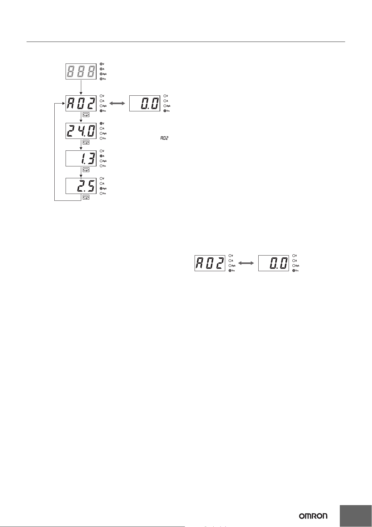
Maintenance Forecast (S8VS-@@@24A@@)
Displays when the maintenance forecast has reached the set value.
Operation
Mode
The maintenance forecast
has reached the set value.
Maintenance
forecast
monitor
Output
voltage
Output
current
Peak-hold
current
(See note.)
Remaining time
until replacement
Note: This indicator alternately
displays alarm ( )
and the maintenance
time until replacement.
Indication and Output
When the Product is purchased, “ful” will be indicated. As
electrolytic capacitors deteriorate, indication changes to “
to page 30). “
display for approximately one month after the Power Supply is first
turned ON. The accumulated value will then be displayed depending
on the ambient conditions thereafter. (However, the “
may not appear, depending on the usage environment and the set
value for maintenance forecast.)
ful” will be indicated for the maintenance forecast
hlf” (Refer
hlf” indication
S8VS-06024A:
After the remaining time to maintenance is reduced to less than two
years, indication automatically changes to a value, which decreases
1.5” to “1.0” to “0.5” to “0.0” (year) as the running hours
from “
increase. If the remaining time becomes less than 0.5 year, an alarm
a02) and “0.0” are indicated alternately.
(
S8VS-09024A@@/S8VS-12024A@,
S8VS-18024A@/S8VS-24024A@/S8VS-48024A:
If the maintenance forecast setting L (which can be set arbitrarily from
0.0 to 5.0 years in 0.5-year steps) is set to a value larger than two
years, the indication automatically changes to a value (L - 0.5) after
the remaining time to maintenance is reduced to the set years, and an
a02) and the remaining time are indicated alternately.
alarm (
If the setting is less than 2.0 years, the indication changes to a value
(1.5) after the remaining time becomes less than two years, and after
the remaining time becomes less than the set time, an alarm (
and the remaining time (L - 0.5) are indicated alternately.
If the alarm (
transistor (maintenance forecast output terminal (Yrs)) will turn OFF
to indicate the need for maintenance. (The transistor turns OFF when
the maintenance forecast time is reached, i.e., there will be no
continuity at the maintenance forecast output terminal.)
Note: 1. The remaining time to maintenance is based on continuous
a02) and a numeric value are indicated alternately, a
In the case that the
remaining time is
reduced to smaller
than 0.5 year and an
alarm is issued.
operation, not including the time when the power supply is
turned OFF.
ful” will be indicated until approximately one month of
2. “
time is accumulated to estimate the speed of deterioration
and the output will remain ON (continuity at the
maintenance forecast output terminal (Yrs)).
3. For details on the display, refer to Relationship between
Indicated Values and Output of Set Values under
Maintenance Forecast Monitor Function on page 30.
a02)
29
Page 30

S8VS
Maintenance Forecast Monitor Function
The Power Supply is equipped with electrolytic capacitors.
The electrolyte inside the electrolytic capacitor penetrates the sealing
rubber and evaporates as time passes since it is manufactured, which
causes deterioration of characteristics such as decreasing the
capacitance, etc.
Due to this deterioration of the characteristics of the electrolytic
capacitor, the Power Supply decreases its performance as time
passes.
Relationship between Indicated Values and Output of Set Values
Initial capacity
Capacity level
at replacement
L: Maintenance forecast set value (See note.)
0.0 to 5.0, 0.5 steps
(L−0.5)
In case of setting L between 2.5 and 5.
The maintenance forecast monitor function shows an approximate
period left for maintenance of the Power Supply due to deterioration
of electrolytic capacitors. When the period left for maintenance that
the power supply forecasts reaches the set value, an alarm is
indicated and an output signal is triggered.
Use this function to know the approximate replacement timing of the
Power Supply.
Note: The maintenance forecast monitor function indicates an
approximate period left for maintenance, based on
deterioration of the electrolytic capacitor. It does not predict
failures caused by other reasons.
"1.0" is displayed on the main display for the
duration that the maintenance forecast up to
replacement satisfies the condition 1.0 ≤ T < 1.5.
Main displayCapacity of Capacitor
Maintenance forecast monitor output
L=2.5
L=0.5
5.0
The numerical value
decreases with time.
2.5 2.0 1.5 1.0 0.5 0
T: Maintenance time
until replacement
Note: This function can be set only on the S8VS-09024A@@, S8VS-12024A@, S8VS-18024A@, S8VS-24024A@, and S8VS-48024A.
Principle of Operation
The deterioration speed of the electrolytic capacitor varies
considerably according to the ambient temperature. (Generally the
speed follows “Rule of Two for every 10°C”; for every 10°C increase
in temperature the rate of degradation doubles according to
Arrhenius’s equation.) The S8VS-@@@24A@@ monitors the
temperature inside the power supply, and calculates the amount of
deterioration according to the running hours and inside temperature.
Judging by this amount of deterioration, the power supply will give the
alarm indication and output when the period left for maintenance
reaches the set value.
Note: 1. Due to degradation of internal electronic parts, replace the
power supply approximately 15 years after purchase even if
indication and output of maintenance forecast monitor are
not issued.
2. The maintenance forecast is accelerated or decelerated
according to operating conditions. Periodically check
indication.
3. Acceleration or deceleration of the maintenance forecast
may cause the output to repeatedly go ON/OFF.
Only the S8VS-09024A@@, S8VS-12024A@, S8VS18024A@, S8VS-24024A@, and S8VS-48024A are
equipped with output.
4. The accuracy of the maintenance forecast function may be
Reference Values (15-W to 480-W Models)
Item Value Definition
MTBF stands for Mean Time
Reliability
(MTBF)
135,000 hr min.
480 W:
60,000 hr min.
15 W to 240 W:
Life
expectancy
10 yr min.
Note: The maintenance forecast is the service life (the power
supply’s internal temperature is monitored at all times) of the
internal electrolytic capacitor in actual operating conditions,
and varies according to the customer’s operating conditions.
15 years is taken as the maximum period of the maintenance
forecast.
Between Failures, which is
calculated according to the
probability of accidental device
failures, and indicates reliability of
devices.
Therefore, it does not necessarily
represent the life of the Product.
The life expectancy indicates
average operating hours under the
ambient temperature of 40°C and a
load rate of 50%. Normally this is
determined by the life expectancy of
the built-in aluminum electrolytic
capacitor.
adversely affected by applications in which the AC input is
frequently turned ON/OFF.
30
Page 31

S8VS
Models with Total Run Time Monitor
(S8VS-@@@24B@@/S8VS-@@@24BE@)
S8VS-06024B
The accumulated value of the operating time of the Power Supply is
displayed as the total run time.
purchase and then the display will advance in 1-kh steps as the
operating time accumulates. The S8VS-06024B, however, does not
have an alarm function (setting, display, or output).
S8VS-09024B@@/S8VS-09024BE@/
S8VS-12024B@/S8VS-12024BE/
S8VS-18024B@/S8VS-18024BE/
S8VS-24024B@/S8VS-24024BE/S8VS-48024B
The display will appear when the set value for the total run time has
been reached.
Operation mode
Total run time
Output
voltage
0 (kh) will be displayed initially after
Total run time set value reached.
(See note.)
Total run time
Note: The alarm (a02)
and the total run
time will be
displayed
alternately.
Time Chart
Total run time
50 kh
0 kh
AC input
Alarm output
Set value = 50 kh
(See note.)
* Setting is possible for the following models only:
S8VS-09024B@@, S8VS-09024BE@, S8VS-12024B@,
S8VS-12024BE, S8VS-18024B@, S8VS-18024BE,
S8VS-24024B@, S8VS-24024BE, S8VS-48024B
Note: 1. The total run time does not include the time that the Power
Supply is OFF.
2. The total run time measures the total time that power is
being supplied and is not related in any way to deterioration
in the electrolytic capacitor built into the Power Supply or to
the effects of the ambient temperature.
Output
current
Peak hold
current
The accumulated value of the operating time of the Power Supply is
displayed as the total run time.
purchase and then the display will advance in 1-kh steps as the
operating time accumulates. When the total run time reaches the
alarm set value, the alarm (
displayed alternately and a transistor (total run time output terminal
(kh)) will output the status externally.
(Alarm set value reached = OFF, i.e., no continuity at the total run time
output terminal (kh))
The alarm set value can be changed in the setting mode.
The S8VS-09024BE@, S8VS-12024BE, S8VS-18024BE, and S8VS24024BE do not have an alarm output.
Example: Alarm Displays When a Total Run Time Set Value of
88 kh Is Reached
Note: The total run time cannot be reset. To clear the alarm, change
the alarm set value to a value higher than the value displayed
for the total run time.
0 (kh) will be displayed initially after
a02) and the total run time will be
31
Page 32

S8VS
Safety Precautions
!CAUTION
Minor electric shock, fire, or Product failure may
occasionally occur. Do not disassemble, modify, or
repair the Product or touch the interior of the
Product.
Minor burns may occasionally occur. Do not touch
the Product while power is being supplied or
immediately after power is turned OFF.
Fire may occasionally occur. Tighten terminal screws
to the specified torque (15- and 30-W models: 0.8 to
1.0 N·m/60-, 90-,120-, 180-, 240-, and 480-W models:
1.08 N·m).
Minor injury due to electric shock may occasionally
occur. Do not touch the terminals while power is
being supplied. Always close the terminal cover after
wiring.
Minor electric shock, fire, or Product failure may
occasionally occur. Do not allow any pieces of metal
or conductors or any clippings or cuttings resulting
from installation work to enter the Product.
Precautions for Safe Use
Wiring
• Connect the ground completely. A protective earthing terminal
stipulated in safety standards is used. Electric shock or malfunction
may occur if the ground is not connected completely.
• Minor fire may possibly occur. Ensure that input and output
terminals are wired correctly.
• Do not apply more than 100-N force to the terminal block when
tightening it.
• Be sure to remove the sheet covering the Product for machining
before power-ON so that it does not interfere with heat dissipation.
• When wiring a screwless terminal block, do not insert more than
one wire into a single terminal.
• When using a screwless terminal block, connect or disconnect the
I/O wire to each terminal while inserting an appropriate tool, such
as a flat-blade screwdriver, into the tool insertion hole. Make sure
that the wire is securely connected to the terminal after wiring. Do
not insert wires into the tool insertion holes.
If a wire is not inserted far enough or if it is loose, electric shock,
fire, or equipment failure may occur. Strip the wires according to
specifications. Insert an appropriate tool, such as a flat-blade
screwdriver, into the tool insertion hole, insert the wire until the
stripped portion is no longer visible, and then remove the tool.
Make sure that the wires are securely connected to the terminal
block after wiring. Never insert wires into the tool insertion holes.
Wire hole
Mounting
• Take adequate measures to ensure proper heat dissipation to
increase the long-term reliability of the Product. Be sure to allow
convection in the atmosphere around devices when mounting. Do
not use in locations where the ambient temperature exceeds the
range of the derating curve.
• When cutting out holes for mounting, make sure that cuttings do
not enter the interior of the Products.
*1
*1. Convection of air
*2
*1
15-W and 30-W Models
• Improper mounting will interfere with heat dissipation and may
occasionally result in deterioration or damage of internal parts. Use
the Product within the derating curve for the mounting direction that
is used.
• Use a mounting bracket when the Product is mounted facing
horizontally.
• Heat dissipation will be adversely affected. When the Product is
mounted facing horizontally, always place the side with the label
facing upward.
• Operate the Power Supply within a range that is 5°C less than the
values in the derating curve in Engineering Data on page 18 if the
Power Supply is used with an installation spacing of 10 mm min.
(20 mm max.) on the left and right.
60-W, 90-W, 120-W, 180-W, 240-W, and 480-W Models
• Improper mounting will interfere with heat dissipation and may
occasionally result in deterioration or damage of internal parts. Use
the standard mounting method only.
• The internal parts may occasionally deteriorate and be broken due
to adverse heat radiation. Do not loosen the screw on the side face
of the main body.
*2. 20 mm min.
3.7 mm
Tool insertion hole
• Use the following material for the wires to be connected to the
S8VS to prevent smoking or ignition caused by abnormal loads.
Recommended Wire Type
15-W and 30-W Models
Model Stranded wire Solid wire
S8VS-03005
Other models
AWG18 to 14
(0.9 to 2.0 mm
AWG20 to 14
(0.5 to 2.0 mm
2
)
2
)
AWG18 to 16
(0.9 to 1.1 mm2)
AWG20 to 16
(0.5 to 1.1 mm2)
60-W, 90-W, 120-W, 180-W, 240-W, and 480-W Models
Recommended wire size
Model
S8VS-06024@
S8VS-
09024@@@@
S8VS12024@@@
S8VS18024@@@
S8VS24024@@@
S8VS-48024@
Input
terminals
AWG14 to 20
(Cross section:
0.517 to
2.081 mm
2
)
AWG 14 to 16
(Cross section:
1,309 to
2,081 mm
2
)
Output
terminals
AWG14 to 20
(Cross section:
0.517 to
2.081 mm
2
)
AWG14 to 18
(Cross section:
0.823 to
2.081 mm
2
)
AWG14 to 16
(Cross section:
1.309 to
2.081 mm
2
)
AWG14
(Cross section:
2.081 mm
2
)
Alarm output
terminals
---
AWG18 to 28
(Cross
section: 0.081
to 0.823 mm
(Wires to be
stripped:
9 to 10 mm)
2
)
32
Page 33

S8VS
• Strip I/O wires for 11 mm when using a screwless terminal block.
* The rated current for output terminals is 10 A per terminal. Be sure
to use multiple terminals simultaneously for current that exceeds
the terminal rating. When applying a current of 10 A or more, use at
least two terminals each for the positive and negative wires.
Installation Environment
• Do not use the Power Supply in locations subject to shocks or
vibrations. In particular, install the Power Supply as far away as
possible from contactors or other devices that are a vibration
source.
• Install the Power Supply well away from any sources of strong,
high-frequency noise and surge.
Operating Life
• The life of a Power Supply is determined by the life of the
electrolytic capacitors used inside. Here, Arrhenius Law applies,
i.e., the life will be cut in half for each rise of 10°C or the life will be
doubled for each drop of 10°C. The life of the Power Supply can
thus be increased by reducing its internal temperature.
Ambient Operating and Storage Environments
• Store the Power Supply at a temperature of −25 to 65°C and a
humidity of 25% to 90%.
• Do not use the Power Supply in areas outside the derating curve
otherwise, internal parts may occasionally deteriorate or be
damaged.
• Use the Power Supply at a humidity of 25% to 85%.
• Do not use the Power Supply in locations subject to direct sunlight.
• Do not use locations where liquids, foreign matter, or corrosive
gases may enter the interior of Products.
S8VS-@@@24A@@ Models only
Satisfy the following conditions when storing the Power Supply for
long periods of time to maintain its remaining service life function.
When storing for more than three months, store within an ambient
temperature range of −25 to +30°C and the humidity range of 25% to
70%.
Periodic Check for Models with Indication
Monitor Except 60-W Models
It may take from several years to more than 10 years under general
operating conditions for the power supply to output the maintenance
forecast monitor alarm (S8VS-@@@24A@@). The total run time
monitor (S8VS-@@@24B@@/S8VS-@@@24BE@) may be a similar
number of years as the maintenance forecast monitor according to
some settings. During operation over an extended period of time,
periodically check if the maintenance forecast monitor output (Yrs) or
total run time monitor output (kh) is correctly functioning by the
following procedure.
1. Select the operation mode.
2. Check that the output (Yrs/kh) is turned ON (with continuity).
3. In the operation mode, press and hold the Down Key D (10) and
the Mode Key M (8) simultaneously
The main display (6) changes to “
An inactive output (Yrs/kh) (no continuity) in the “
indicates the correct function.
4. Release keys to return to the regular state.
Note: DC output stays ON during the periodical check.
for at least three seconds.
a02.”
a02” indication
60-, 90-, 120-,
1
2
180-, 240-W
Models
76
10
12
(Yrs/kh)
11
(DC LOW)
13
(COMMON)
3
8
9
4
5
480-W Models
12
6
7
10
16
15
9
11
12
13
14
(Yrs/kh)
(DC LOW)
8
4
5
3
Overcurrent Protection
• Internal parts may possibly deteriorate or be damaged if a
short-circuited or overcurrent state continues during operation.
• Internal parts may possibly deteriorate or be damaged if the Power
Supply is used for applications with frequent inrush current or
overloading at the load end. Do not use the Power Supply for such
applications.
• The DC ON indicator (green) flashes if the overload protection
function operates.
Alarm Output for Models with Indication Monitor
Except 60-W and BE Models
When using the alarm output, sufficiently consider the maximum
ratings, residual voltage, and leakage current.
Transistor output: Sinking for S8VS-24A@/@@@24B@ models
Sourcing for S8VS-@@@24AP@/@@@24BP@
models
Sinking/Sourcing for S8VS-48024A/B models
30 VDC max., 50 mA max.
ON residually voltage:2 V max.
OFF leakage current: 0.1 mA max.
Charging a Battery
If you connect a battery as the load, install overcurrent control and
overvoltage protection circuits.
33
Page 34

S8VS
Output Voltage Adjuster (V.ADJ)
• The output voltage adjuster (V.ADJ) may possibly be damaged if it
is turned with unnecessary force. Do not turn the adjuster with
excessive force.
• After completing output voltage adjustment, be sure that the output
capacity or output current does not exceed the rated output
capacity or rated output current.
15-W, 30-W Models
• If the output voltage is set to a value less than −10%, the
undervoltage alarm function may operate.
60-W, 90-W, 120-W, 180-W, 240-W, and 480-W Models
• If the detection voltage of the undervoltage alarm function is at the
factory setting and the output voltage is set to a value of 20 V or
less, the undervoltage alarm function may operate.
DIN Rail Mounting
To mount the Block on a DIN Rail, hook portion (A) of the Block onto
the rail and press the Block in direction (B).
(A)
(B)
To dismount the Block, pull down portion (C) with a flat-blade
screwdriver and pull out the Block.
30 mm min.
Track stopper
(C)
Series Operation
(24-V Model)
Two power supplies can be connected in series.
Correct
Note: 1. The diode is connected as shown in the figure. If the load is
short-circuited, a reverse voltage will be generated inside
the Power Supply. If this occurs the Power Supply may
possibly deteriorate or be damaged. Always connect a
diode as shown in the figure.
Select a diode having the following ratings.
Type Schottky Barrier diode
Dielectric strength (V
Forward current (I
2. Although Products having different specifications can be
connected in series, the current flowing through the load
must not exceed the smaller rated output current.
3. Serial operation is not possible with 5-V and 12-V models.
Making Positive/Negative Outputs
• The outputs are floating outputs (i.e., the primary circuits and
secondary circuits are separated). You can therefore make
positive and negative outputs by using two Power Supplies.
You can make positive and negative outputs with any of the
models.
If positive and negative outputs are used, connect Power Supplies
of the same model as in the following figure. (Combinations with
different output capacities or output voltages can be made.
AC (L)
AC (N)
AC (L)
AC (N)
RRM) Twice the rated output voltage or above
F) Twice the rated output current or above
+V
−V
+V
−V
However, use the lower of the two maximum rated output currents
as the current to the loads.)
INPUT
INPUT
+V
−V
+V
−V
+V
Load
0 V
Load
−V
• Depending on the model, internal circuits may be damaged due to
startup failure when the power is turned ON if loads such as a
servomotor or operational amplifier may operate in series.
Therefore, connect bypass diodes (D1, D2) as shown in the
following figure.
If the list of models that support series connection of outputs says
that an external diode is not required, an external diode is also not
required for positive/negative outputs.
+V
INPUT
INPUT
D1
−V
+V
D
2
−V
Load
Load Load
• Use the following information as a guide to the diode type, dialectic
strength, and current.
• Type: Schottky barrier diode
• Dielectric strength (V
RRM): Twice the rated Power Supply output
voltage or higher
• Forward current (I
F): Twice the rated Power Supply output
current or higher
Parallel Operation
The Product is not designed for parallel operation.
Incorrect
AC (L)
AC (N)
AC (L)
AC (N)
+V
−V
+V
−V
Backup Operation
•
B
ackup operation can be performed. Backup operation provides
protection by using an extra Power Supply even if the output
current is sufficient with one Power Supply. If one of the Power
Supplies fails, the second Power Supply still provides sufficient
power.
A
B
Use the same model for Power Supplies A and B.
• Use a load capacity that can be supplied by either Power Supply A
or Power Supply B alone.
• If backup operation is used, be sure to connect a diode to both
Power Supply A and Power Supply B as shown in the above figure
so that the backup Power Supply is not affected by a failed Power
Supply.
Use the following information as a guide to the diode type, dialectic
strength, and current.
1
D
+V
−V
D2
+V
−V
Load
34
Page 35

• Type: Schottky barrier diode
• Dielectric strength (V
higher
• Forward current (I
current or higher
• Increase the output voltage setting of Power Supply A and Power
Supply B by the drop in the forward voltage (V
D2.
Also, the diodes will cause a power loss equivalent to the Power
Supply output current (I
Therefore, cooling measures must be implemented so that the
temperature of the diodes decreases to the catalog value or lower.
• Because of the load power and power loss due to the diodes, do
not exceed the rated power of one Power Supply (rated output
voltage x rated output current).
RRM): Rated Power Supply output voltage or
F): Twice the rated Power Supply output
F) of diodes D1 and
OUT) times the diode forward voltage (VF).
In Case There Is No Output Voltage
The possible cause for no output voltage may be that the overcurrent
or overvoltage protection has operated. The internal protection may
operate if a large amount of surge voltage such as a lightening surge
occurs while turning ON the power supply.
In case there is no output voltage, please check the following points
before contacting us:
• Checking overload protected status:
Check whether the load is in overload status or is short-circuited.
Remove wires to load when checking.
• Checking overvoltage or internal protection:
Turn the power supply OFF once, and leave it OFF for at least
3 minutes. Then turn it ON again to see if this clears the condition.
S8VS
Audible Noise at Power ON
(120-W, 180-W, 240-W, and 480-W Models)
A harmonic current suppression circuit is built into the Power Supply.
This circuit can create noise when the input is turned ON, but it will
last only until the internal circuits stabilize and does not indicate any
problem in the Product.
ALL DIMENSIONS SHOWN ARE IN MILLIMETERS.
To convert millimeters into inches, multiply by 0.03937. To convert grams into ounces, multiply by 0.03527.
In the interest of product improvement, specifications are subject to change without notice.
35
Page 36

MEMO
36
Page 37

Read and Understand this Catalog
Please read and understand this catalog before purchasing the product. Please consult your OMRON representative if you have
any questions or comments.
Warranty and Limitations of Liability
WARRANTY
OMRON's exclusive warranty is that the products are free from defects in materials and workmanship for a period of one year
(or other period if specified) from date of sale by OMRON.
OMRON MAKES NO WARRANTY OR REPRESENTATION, EXPRESS OR IMPLIED, REGARDING NON-INFRINGEMENT,
MERCHANTABILITY, OR FITNESS FOR PARTICULAR PURPOSE OF THE PRODUCTS. ANY BUYER OR USER
ACKNOWLEDGES THAT THE BUYER OR USER ALONE HAS DETERMINED THA T THE PR ODUCTS WILL SUIT ABLY MEET
THE REQUIREMENTS OF THEIR INTENDED USE. OMRON DISCLAIMS ALL OTHER WARRANTIES, EXPRESS OR
IMPLIED.
LIMITATIONS OF LIABILITY
OMRON SHALL NOT BE RESPONSIBLE FOR SPECIAL, INDIRECT , OR CONSEQUENTIAL D AMAGES , LOSS OF PROFITS,
OR COMMERCIAL LOSS IN ANY WAY CONNECTED WITH THE PRODUCTS, WHETHER SUCH CLAIM IS BASED ON
CONTRACT, WARRANTY, NEGLIGENCE, OR STRICT LIABILITY.
In no event shall the responsibility of OMRON for any act exceed the individual price of the product on which liability is asserted.
IN NO EVENT SHALL OMRON BE RESPONSIBLE FOR WARRANTY, REPAIR, OR OTHER CLAIMS REGARDING THE
PRODUCTS UNLESS OMRON'S ANALYSIS CONFIRMS THAT THE PRODUCTS WERE PROPERLY HANDLED, STORED,
INSTALLED, AND MAINTAINED AND NOT SUBJECT TO CONTAMINATION, ABUSE, MISUSE, OR INAPPROPRIATE
MODIFICATION OR REPAIR.
Application Considerations
SUITABILITY FOR USE
OMRON shall not be responsible for conformity with any standards, codes, or regulations that apply to the combination of
products in the customer's application or use of the products.
Take all necessary steps to determine the suitability of the product for the systems, machines, and equipment with which it will
be used.
Know and observe all prohibitions of use applicable to this product.
NEVER USE THE PRODUCTS FOR AN APPLICATION INVOLVING SERIOUS RISK TO LIFE OR PROPERTY WITHOUT
ENSURING THA T THE SYSTEM AS A WHOLE HAS BEEN DESIGNED T O ADDRESS THE RISKS, AND THAT THE OMRON
PRODUCTS ARE PROPERLY RATED AND INST ALLED FOR THE INTENDED USE WITHIN THE O VERALL EQUIPMENT OR
SYSTEM.
PROGRAMMABLE PRODUCTS
OMRON shall not be responsible for the user’s programming of a programmable product, or any consequence thereof.
Disclaimers
CHANGE IN SPECIFICATIONS
Product specifications and accessories may be changed at any time based on improvements and other reasons.
It is our practice to change model numbers when published ratings or features are changed, or when significant construction
changes are made. However, some specifications of the products may be changed without any notice. When in doubt, special
model numbers may be assigned to fix or establish key specifications for your application on your request. Please consult with
your OMRON representative at any time to confirm actual specifications of purchased products.
DIMENSIONS AND WEIGHTS
Dimensions and weights are nominal and are not to be used for manufacturing purposes, even when tolerances are shown.
PERFORMANCE DATA
Performance data given in this catalog is provided as a guide for the user in determining suitability and does not constitute a
warranty. It may represent the result of OMRON’s test conditions, and the users must correlate it to actual application
requirements. Actual performance is subject to the OMRON Warranty and Limitations of Liability.
Page 38

OMRON Corporation Industrial Automation Company
Tokyo, JAPAN
Contact: www.ia.omron.com
Regional Headquarters
OMRON EUROPE B.V.
Wegalaan 67-69-2132 JD Hoofddorp
The Netherlands
Tel: (31)2356-81-300/Fax: (31)2356-81-388
OMRON ASIA PACIFIC PTE. LTD.
No. 438A Alexandra Road # 05-05/08 (Lobby 2),
Alexandra Technopark,
Singapore 119967
Tel: (65) 6835-3011/Fax: (65) 6835-2711
OMRON ELECTRONICS LLC
One Commerce Drive Schaumburg,
IL 60173-5302 U.S.A.
Tel: (1) 847-843-7900/Fax: (1) 847-843-7787
OMRON (CHINA) CO., LTD.
Room 2211, Bank of China Tower,
200 Yin Cheng Zhong Road,
PuDong New Area, Shanghai, 200120, China
Tel: (86) 21-5037-2222/Fax: (86) 21-5037-2200
Authorized Distributor:
© OMRON Corporation 2002 All Rights Reserved.
In the interest of product improvement,
specifications are subject to change without notice.
CSM_5_2_0312
Cat. No. T026-E1-08
Printed in Japan
0312
 Loading...