

Page 1
Easy to Read and
Easy to Understand
RFID
Technical Guide
Page 2

Table of
Contents
What is RFID? ....................................................... 3
Types of RFID.......................................................6
OMRON’s RFID Products: Features.....................10
Precautions for Use ...........................................15
Page 3
1
What is RFID?
What is RFID?
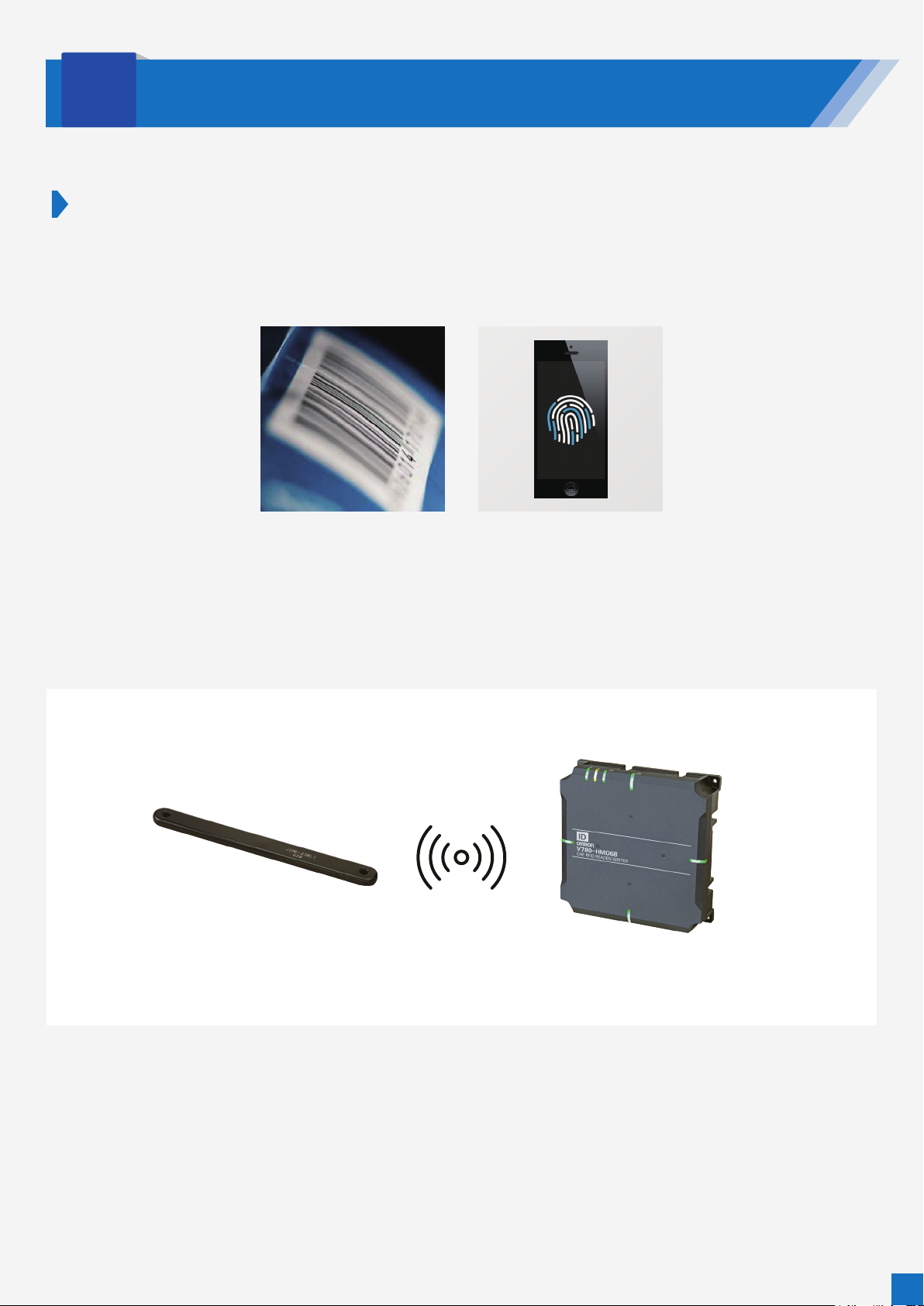
Automatic identification (auto ID) is a process where people and things are automatically identified. Some familiar
examples are barcodes used to identify products and fingerprint authentication used by smartphones to identify users.
Radio frequency identification, or RFID, is an auto ID technology whereby reader/writers use radio waves to capture
information recorded on RF tags.
RF tag Reader/writer
Radio waves
Data recorded to tag Reads data from RF tag
(or writes data to RF tag)
3
Page 4
Strong Points
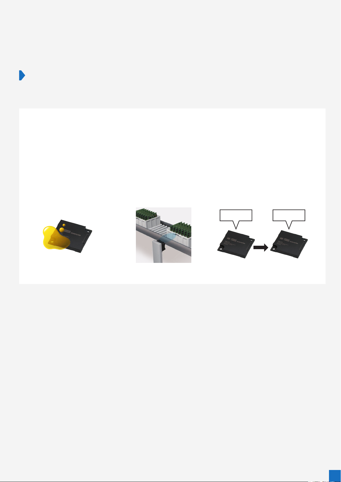
RFID has the following advantages over barcodes and other auto ID technologies.
1. Relatively stain-resistant.
2. RF tags can be read from or written to even when they are not in close proximity to the
reader/writer (as long as they are within the reach of the radio energy used for
communication).
3. Data can be rewritten.
AAAA BBBB
Stain-resistant Tags can be read from/
written to if within communication range
Rewritable
4
Page 5
Common Applications of RFID
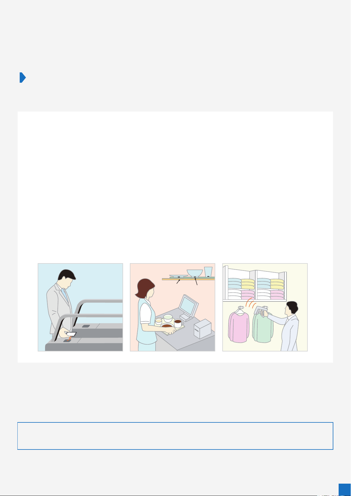
RFID has many applications that take advantage of the technology’s strong points.
1. Railway ticket gates
Transit fare cards (e.g. Suica) use RF tags.
Information encoded in the card is read to control ticket gate operation.
The tags are rewritable, making them perfect for storing balance and other information.
2. Cafeteria checkout counter
RF tags are attached to all tableware used at the cafeteria to enable an unmanned
automatic checkout system.
3. Store product management
A major clothing manufacturer attaches RF tags to their products to streamline inventory
management.
Cafeteria
POS antenna
With the Ministry of Economy, Trade and Industry (METI) of Japan planning to attach RF tags to all products sold in
convenience stores by 2025, RFID is sure to become even more pervasive in our daily lives.
Reference: METI website
https://www.meti.go.jp/english/press/2017/0418_003.html
RF tag
5
Page 6
2
Types of RFID
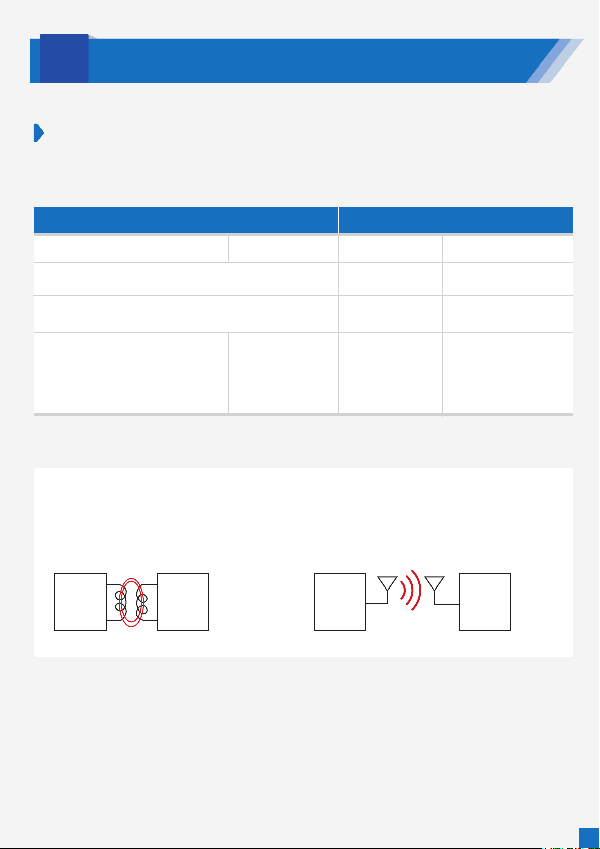
Categorized by Frequency Band
The chart below groups RFID according to the frequency band used for communication.
Each type has its strong and weak points, and so should be selected according to purpose.
Electromagnetic inductionTransmission method
135 kHz or lowerUsed frequencies 13.56 MHz
Communication
range
Oil/chemical resistance
(impact of moisture)
Application
Fair
A few to a few dozen cm
Good
(no impact)
Relatively limited
range of usage
Widely used in a vast
range of applications
(virtually unaffected by
all substances except
metals and therefore
highly versatile)
Electromagnetic induction Radio wave
Radio wave
920 MHz 2.4 GHz
Good
A few meters
Fair
(substantial impact)
Warehouse gates
(because it can
communicate over
long distances)
Good
A few to a few dozen meters
Fair
(substantial impact)
Mostly active RFID
Uses magnetic fields for coupling.
Suited for short-range communication, for drop off in field
strength is inversely proportional to the distance squared.
Magnetic fields are virtually unaffected by water
Reader/writer RF tag Reader/writer RF tag
Uses radio waves for coupling.
Can communicate over long distances, for drop off in field strength
is inversely proportional to the distance.
Greatly affected by water
6
Page 7

Categorized by Power Supply
RFID can also be grouped into three groups according to how tags are powered: passive, semi-passive, and active.
Passive RFID
Features
RF tag battery
Communication
method
Mechanism
The most distinguishing feature of passive RFID is that its RF tags have no batteries.
This allows for a low-cost, maintenance-free system, which would not be possible with other wireless
technologies (e.g. Wi-Fi and Bluetooth), suited for tasks that require the identification of a large number of
subjects, such as inventory management and production management.
The RF tags do not emit radio waves but talk back to reader/writers using backscatter modulation.
None
The tag harvests its internal operating power by rectifying high-frequency signals it receives from the
reader/writer (using power supply shown in green in block diagram), which means its internal circuit
operates only when it is within communication range of the reader/writer.
Backscatter
RF tag does not need its own oscillator to signal to the reader/writer, and this reduces power
consumption (modulator shown in orange in block diagram).
Block diagram
Reader/writer RF tag
Host
Controller
I/F
Modulator
Demodulator
Amplifier
Oscillator
Electromagnetic
induction
Modulator
(Backscatter modulator)
Demodulator
Power supply
(Rectifier)
Controller Memory
Powers various RF tag components
7
Page 8

Semi-passive RFID
Features
RF tag battery
Communication
method
Mechanism
In a semi-passive RFID system, the method of communication between RF tags and reader/writers is the same as in a
passive RFID system. The difference is that RF tags in a semi-passive system have batteries to enable functions that are
not possible in a passive RFID system.
Some representative examples of sensing without receiving power from reader/writers are temperature data logging
during transport, and long-distance communication that passive RFID systems would not be able to provide.
Built-in battery
RFID components are powered by battery, so internal circuits can operate even when tag is outside
reader/writer communication range (sensor is shown in blue in block diagram).
Backscatter
RF tag does not need its own oscillator to signal to the reader/writer, and this reduces power consumption
(modulator shown in orange in block diagram).
Block diagram
Reader/writer RF tag
Upper
layer
I/F
Controller
Modulator
Demodulator
Amplifier
Oscillator
Electromagnetic
induction
Modulator
(Backscatter modulator)
Demodulator
Power supply
(battery)
Controller
Powers various
RF tag components
Memory
Sensor
Features
RF tag battery
Communication
method
Mechanism
Active RFID
Unlike passive and semi-passive RFID tags, active RFID tags generate their own radio frequency signals, enabling long-distance
communication.
Because the tags are battery-powered, it is critical that information is delivered efficiently with minimum power consumption.
Active RFID is used, for example, to monitor electricity meters and gas meters, and for managing sea freight containers at ports.
Built-in battery
RFID parts are powered by battery, so internal circuits can operate even when tag is outside reader/writer
communication range (sensor is shown in blue in block diagram).
Each equipment have Continuous Wave (CW) oscillator
Block diagram
Reader/writer
Upper
layer
I/F
Controller
Modulator
Demodulator
Oscillator
Amplifier
Electromagnetic
induction
RF tag
Amplifier Modulator
Demodulator
Power supply
(battery)
Oscillator
Controller
Powers various
RF tag components
Memory
Sensor
8
Page 9

Supplement: How Does Backscatter Communication Work?
This section explains how backscatter communication, used in passive and semi-passive RFID, works.
In passive and semi-passive RFID, energy from the reader/writer cannot sufficiently power an oscillator circuit
inside the RF tag. The backscatter technique enables tags to talk back to reader/writers without an oscillator
circuit.
Changing the impedance of the load modulation circuit in the RF tag from Z1 to Z2 while continuous waves (CW)
are being transmitted from the reader/writer changes the amplitude of the CW signals that reflect off the tag.
Passive and semi-passive RF tags apply this principle by switching their circuit impedance between Z1 and Z2 to
translate their response signals (0/1) into changes in the amplitude of the CW signals reflected off of them, a
technique known as backscatter modulation.
The reader/writer then demodulates the modulated RF waves.
In using this method, the RF tags themselves do not emit RF waves and so are not considered as radio equipment
under Japanese Radio Law.
CW
Amplitudes of
reflected waves
change
RF tagReader/writer
Load modulation circuit
Reflection
Z1
Z2
0/1
Z1 Z1Z2
9
Page 10

3
OMRON’s RFID Products: Features
OMRON’s RFID products boast an extensive on-the-ground track record in the field of factory
automation over more than 30 years. In keeping with this proud history, we continue to strive to
develop RFID technologies our customers can rely on.
1. Guaranteed Communication Range (V600/V680/V680S Series)
The communication range of an RFID system may fluctuate due to a range of factors, such as equipment temperature
and variation among different units.
In electromagnetic induction RFID systems, tags and reader/writers communicate via the connection between their
coils. Increasing the Q-factors of the coils can increase the communication range, but this comes with the risk of
increasing communication range fluctuation as well.
At OMRON, we define a guaranteed communication range for each of our RFID products that takes these points into
consideration.
We also test to make sure that there are no blind spots in the designated range, ensuring reliability as long as the units
are used within its limits.
Sample communication range specifications (guaranteed range)
Amplifier Antenna RF tag Communication range
V680-HA63B
V680-HS51
V680-HS51
V680-HS52
V680-HS52
V680-HS63
V680-D2KF52M
V680-D2KF52M
(Embedded in metal (iron))
V680-D2KF52M
V680-D2KF52M
(Embedded in metal (iron))
V680-D2KF52M
Read
Write
Read
Write
Read
Write
Read
Write
Read
Write
0.5 to 5.5 mm (axis offset ±2 mm)
0.5 to 5.5 mm (axis offset ±2 mm)
0.5 to 3.5 mm (axis offset ±2 mm)
0.5 to 3.5 mm (axis offset ±2 mm)
0 to 8.0 mm (axis offset ±2 mm)
0 to 8.0 mm (axis offset ±2 mm)
0 to 3.0 mm (axis offset ±2 mm)
0 to 3.0 mm (axis offset ±2 mm)
0 to 9.5 mm (axis offset ±2 mm)
0 to 9.5 mm (axis offset ±2 mm)
Sample communication range diagram (reference)
V680-HS52 (embedded in non-metal material) + V680-D2KF52M
• Read/write
Y
Y
30
X
20
10
–40 –30 –20 –10 0 10 20 30 X
No blind spots within designated range
10
Page 11

2. Visualization (V680S/V780)
Because magnetic fields and RF waves are not visible to the naked eye, it is impossible for humans to visibly verify
whether reader/writers and RF tags are communicating with sufficient leeway.
Installing or configuring the system without allowing for a generous margin may cause abrupt communication failure in
the midst of operations or make it difficult to determine the cause of such failures.
OMRON’s RFID products come equipped with various visualization tools that incorporate feedback from engineers who
have actually configured systems on the ground, ensuring reliability for a wide range of users, from those in charge of
installation to those tasked with maintenance.
Status visualization by reader/writer LEDs
Visualization of
communications status
Good Error
Diagnosis of Communications
Warning
LEDs on reader/writer allow for on-site, at-a-glance view of communications status.
High-brightness LEDs used for indicators make them readily visible even from a great distance.
Also...
The reader/writer measures the communications signal and ambient noise levels to diagnose its stability,
then indicates in LED and report to host system.
Easily and quickly checks the proper installation of the system, and helps to reduce startup time.
This can be used for preventing errors during operation.
Communications status visible
from five directions
From above
From left From right
From front
Indicates “Warning” states communication in yellow
Note: 1. Communication Diagnostic feature is disabled by default.
2. Enabling the Communication Diagnostic feature increases communication time.
For details, refer to the User’s Manual (Cat. No. Z339 or Z353).
11
Page 12

Status visualization by web browser interface
Web Browser I/F
Enable all parameter settings, execute RF tag
communications, and check the operation log
anywhere by just connecting the computer.
Easy Troubleshooting
Up to 2,000 communication results are stored
and guidance for the “Warning” results is provided. Can be
quickly recovered from trouble without expert knowledge.
List display
Displays diagnostic logs for the past 2,048
communication sessions between the
reader/writer and RF tags.
Guidance window
Troubleshoot is also available in the
“Warning” results.
Charts
Diagnostic results can be shown by the graph.
Analysis time required to identify the cause of unstable communication
can be reduced by checking the time-series signal and noise levels.
The results can be output to CSV files.
3. Compliance to Radio Laws in Different Countries
Different countries have different radio laws, which means that equipment needs to be approved for use specifically in
the country where it is installed.
OMRON’s RFID products are approved for use in 51 countries*1 across the globe—virtually any country of your choice.
Japan
Asia (China, South Korea, Taiwan, Hong Kong, Philippines, Vietnam, Thailand, Singapore, Indonesia, Malaysia, India)
*1: Some models are not approved for use in some countries. See our website (http://www.ia.omron.com/) for details.
Europe Americas (United States, Canada, Mexico, Brazil)
Oceania (Australia, New Zealand)
12
Page 13

4. Technology for Preventing Excessive Reading (V780)
UHF RFID products, which can communicate over long distances, may, by their nature, accidentally detect RF tags
placed at distant locations that are not intended for detection.
In other words, these products sometimes “excessively” read targets.
Our long-range RFID products come equipped with features that prevent such “excessive” reading, ensuring reliability.
Focus Mode prevents excessive reading and reads only target tags
Even when two or more RF tags exist in the
communication range, the reader/writer can read the
target tag just in front of it.
It reads RF tags in the order in which they are
conveyed while ignoring RF tags on pallets around
the line.
(Only when communication mode is set to “Focus”)
*1. PATENT PENDING/PATENTED means that the patent was
applied for or the patent was granted. (As of August 2019)
PATENT PENDING*
1
13
Page 14

Below is an outline of the technology behind this feature.
For more details, read the full technical paper on our technical paper site.
https://www.omron.com/global/en/technology/omrontechnics/vol51/007.html
Stable reading for UHF RFID
Technique for preventing erroneous detection of non-target RF tag
Hidekatsu Nogami
In the automotive industry, the increasing number of recalls is a major issue. Individual identification
technologies, which can help companies handle recalls of their products more quickly by pinpointing when
and where each and every component was manufactured, are therefore becoming more and more important.
Of the many individual identification technologies, RFID has the advantage of being resistant to dirt, oil, and
dust. It can be categorized into two groups according to communication distance: HF RFID for short-range
communication, and UHF RFID for long-range communication. The accuracy of UHF RFID, however, can be
impacted by radio waves reflected off of surrounding structures.
To counter this issue, we developed an algorithm that can distinguish between target and non-target RF tags
by detecting changes in the electrical power radiated from the tags, based on how RF tags move at the
production site. With this technique, a highly reliable long-distance individual identification system can be
achieved.
Received power map
See our website for more.
Transition of electrical power
expected to be received
14
Page 15

4
Precautions for Use
1. Installing Reader/Writers and RF Tags
Communication range may be impacted by metal surrounding the equipment, its installation angle, and mutual
interference. Specific data can be found in the product manual. Please refer to them upon installation.
Example:
When installing V680S-HMD63-ETN
Impact of metal surrounding the reader/writer
Reader/writers can be mounted to the surface or, optionally, embedded in metal to protect them from collision with
other objects, in which case there should be a distance of at least 80 mm between the metal and the reader/writer.
Placing the metal any closer to the reader/writer will significantly reduce its communication range.
The height of the metal should not exceed the height of the reader/writer.
30 mm
max.
Metal
Provide a cable bending radius of
40 mm or more.
CHECK!
The communication range will be reduced significantly if the
reader/writer is installed closer than 80 mm to metal surfaces.
CHECK!
90 mm min.
Radius: 40 mm min.
Metal
80 mm
min.
80 mm min.
80 mm
min.
80 mm min.
2. Communication Time
Communication time may vary due to factors such as the type of RF tag being read or the amount of processing data.
Refer to your manual and make sure to set your communication time with ample margin.
In noisy environments, retries may cause communication to take longer than indicated in the manual. Make sure to
sufficiently test your installation before operation.
Example:
Communication time between V680S-HMD6-ETN and V680-D1KP
The communication time is the time from when the Reader/Writer turns ON the RF
signal until it receives the last bit of the response from the RF Tag.
Command
RF signal
Communications time
Response
V680S-HMD6-ETN and V680-D1KP
There are no differences between
Communication speed: “normal” and “high”.
Query Communication time [ms]
Read
Write (with verification)
Write (without verification)
N: No. of bytes processed
T = 1.0N + 20.1
T = 1.8N + 45.2
T = 1.5N + 41.4
RF signal :
Command :
Response :
Enabling the Communication Diagnostic feature increases communication time
by up to 200 ms.
CHECK!
The radio wave that the Reader/Writer transmits to the RF Tag.
The Reader/Writer turns ON this RF signal and then sends the command to start
communications with the RF Tag.
When the communications end, the Reader/Writer turns OFF the RF signal.
The command that the Reader/Writer sends to the RF Tag.
The response that the RF Tag returns to the Reader/Writer.
600
550
500
450
400
350
300
250
200
150
Communication time [ms]
100
50
0
0 50 100 150 200 250 300
Write (with verification)
Write (without verification)
Read
No. of bytes
15
Page 16

3. Applying for a Premises Radio Station License (V780)
Under Japanese law, V780 is deemed a “premises radio station,” which requires a license for operation.
Follow the instructions in your manual to apply for your license.
For reference, below is an outline of what the process looks like in Japan.
Similar procedures are required in Russia, Singapore, and Thailand, but not in most other countries.
V780-HMD68-EIP-JP/V780-HMD68-ETN-JP-S is a wireless facility of premises radio station to differentiate moving object using the
920-MHz band. The licensing procedures of the premises radio station must be performed before use. Be sure to perform the licensing
procedures before use.
Introduction
As for the licensing procedures of the premises radio station, check the information regarding the latest procedures, and the
documents necessary for the procedures on the Website of the Regional Bureau of Telecommunications.
The licensing procedures involve the submission of an application for a license at the local Regional Bureau of Telecommunications.
A Regional Bureau of Telecommunications falls under the jurisdiction of each district. Please confirm your Regional Bureau of
Telecommunications to perform the procedures.
For details on the Regional Bureau of Telecommunications in each district where you can perform the licensing procedures, refer to the
Radio Use Website of the Ministry of Internal Affairs and Communications
(http://www.tele.soumu.go.jp/e/ref/material/commtab1/index.htm).
Example) For the Kanto area (Ibaraki, Tochigi, Gunma, Saitama, Chiba, Tokyo, Kanagawa and Yamanashi)
Contact the Kanto Bureau of Telecommunications (Website URL: http://www.soumu.go.jp/soutsu/kanto/).
For details on the licensing procedures system, refer to the Radio Use Website of the Ministry of Internal Affairs and Communications
(http://www.tele.soumu.go.jp/e/adm/proc/type/index.htm).
The URL described above is effective as of July 2019.
Flow of Licensing Procedures (Overview)
The licensing procedures involve the submission of an application for a license in order to set up a radio station. When an application
for a license is submitted, a license is issued. Once the license is received, the procedures are complete.
The flow of the licensing procedures is shown below.
Customer
Application
for a license
Receipt of a license
Procedures completed
* Please enclose a self-addressed return envelope for receipt of your license when applying for a license.
* The license is effective for a period of 5 years (you will have to apply again for a license after 5 years.)
* In case of any changes in the license contents or establishment report contents, you will have to perform change
procedures.
* If the license is no longer in use, please submit a discard report.
* If there are any changes in the contact address, or the address for sending the radio use charges payment notice, or any
changes in the station location, you will have to perform change procedures. You are requested to do the needful.
(1) Radio station license application
(2) Radio station statement of matters and
construction type
(3) Configuration diagram
Issued in approx. 3 weeks if there is
no fault
Local Regional Bureau of
Telecommunications
Issuance of license
16
Page 17

Page 18

Note: Do not use this document to operate the Unit.
OMRON Corporation Industrial Automation Company
Kyoto, JAPAN
Contact: www.ia.omron.com
Regional Headquarters
OMRON EUROPE B.V.
Wegalaan 67-69, 2132 JD Hoofddorp
The Netherlands
Tel: (31)2356-81-300/Fax: (31)2356-81-388
OMRON ASIA PACIFIC PTE. LTD.
No. 438A Alexandra Road # 05-05/08 (Lobby 2),
Alexandra Technopark,
Singapore 119967
Tel: (65) 6835-3011/Fax: (65) 6835-2711
OMRON ELECTRONICS LLC
2895 Greenspoint Parkway, Suite 200
Hoffman Estates, IL 60169 U.S.A.
Tel: (1) 847-843-7900/Fax: (1) 847-843-7787
OMRON (CHINA) CO., LTD.
Room 2211, Bank of China Tower,
200 Yin Cheng Zhong Road,
PuDong New Area, Shanghai, 200120, China
Tel: (86) 21-5037-2222/Fax: (86) 21-5037-2200
Authorized Distributor:
© OMRON Corporation 2020 All Rights Reserved.
In the interest of product improvement,
specifications are subject to change without notice.
Cat. No. Q288-E1-01
0320 (0320)
 Loading...