

Page 1

Cat. No. I544-E1-05
USER’S MANUAL
OMNUC W SERIES
MODELS R88M-W@
(AC Servomotors)
MODELS R88D-WN@-ML2
(AC Servo Drivers)
AC SERVOMOTORS/SERVO DRIVERS
WITH BUILT-IN MECHATROLINK-II COMMUNICATIONS
Page 2

Thank you for choosing this OMNUC W-series product. Proper use and handling of the product will ensure proper product performance, will length product life, and may prevent possible
accidents.
Please read this manual thoroughly and handle and operate the product with care.
1.To ensure safe and proper use of your OMRON Servomotors and Servo Drivers, please read this manual
(Cat. No. I544-E1) to gain sufficient knowledge of the products, safety information, and precautions before
actual use.
2.The products are illustrated without covers and shieldings to enable showing better detail in this manual.
For actual use of the products, make sure to use the covers and shieldings as specified.
3.Copies of this manual and other related manuals must be delivered to the actual end users of the products.
4.Please keep a copy of this manual close at hand for future reference.
5.If a product has been left unused for a long time, please consult with your OMRON sales representative.
NOTICE
1.This manual describes the functions of the product and relations with other products. You
should assume that anything not described in this manual is not possible.
2.Although care has been given in documenting the product, please contact your
OMRON representative if you have any suggestions on improving this manual.
The product contains dangerous high voltages inside. Turn OFF the power and wait for at least
3.
five minutes to allow power to discharge before handling or working with the product. Never
attempt to disassemble the product.
4.We recommend that you add the following precautions to any instruction manuals you prepare
for the system into which the product is being installed.
• Precautions on the dangers of high-voltage equipment.
• Precautions on touching the terminals of the product even after power has been turned
OFF. (These terminals are live even with the power turned OFF.)
5.Specifications and functions may be changed without notice in order to improve product performance.
6.Positive and negative rotation of AC Servomotors described in this manual are defined as looking at the end of the output shaft of the motor as follows: counterclockwise rotation is positive
and clockwise rotation is negative.
7.Do not perform withstand-voltage or other megameter tests on the product. Doing so may
damage internal components.
8.Servomotors and Servo Drivers have a finite service life. Be sure to keep replacement products on hand and to consider the operating environment and other conditions affecting the service life.
9.The OMNUC W Series can control both incremental and absolute encoders. Differences in
functions or specifications according to the encoder type are indicated in this manual. Be sure
to check the model that is being used, and follow the relevant specifications.
• Servomotors with incremental encoders: R88M-W@H-@
• Servomotors with absolute encoders: R88M-W@T- @
Items to Check After Unpacking
1.Check the following items after removing the product from the package:
• Has the correct product been delivered (i.e., the correct model number and specifications)?
• Has the product been damaged in shipping?
• Are any screws or bolts loose?
Page 3
USER’S MANUAL
OMNUC W SERIES
MODELS R88M-W@
(AC Servomotors)
MODELS R88D-WN@-ML2
(AC Servo Drivers)
AC SERVOMOTORS/SERVO DRIVERS
WITH BUILT-IN MECHATROLINK-II COMMUNICATIONS
Page 4

Page 5

Notice:
r
f
OMRON products are manufactured for use according to proper procedures by a qualified operator
and only for the purposes described in this manual.
The following conventions are used to indicate and classify precautions in this manual. Always heed
the information provided with them. Failure to heed precautions can result in injury to people or damage to property.
!DANGER Indicates an imminently hazardous situation which, if not avoided, will result in
death or serious injury. Additionally, there may be severe property damage.
!WARNING Indicates a potentially hazardous situation which, if not avoided, could result in
death or serious injury. Additionally, there may be severe property damage.
!Caution Indicates a potentially hazardous situation which, if not avoided, may result in
minor or moderate injury, or property damage.
OMRON Product References
All OMRON products are capitalized in this manual. The word “Unit” is also capitalized when it refers to
an OMRON product, regardless of whether or not it appears in the proper name of the product.
The abbreviation “Ch,” which appears in some displays and on some OMRON products, often means
“word” and is abbreviated “Wd” in documentation in this sense.
The abbreviation “PC” means Programmable Controller and is not used as an abbreviation for anything
else.
Visual Aids
The following headings appear in the left column of the manual to help you locate different types of
information.
Note Indicates information of particular interest for efficient and convenient operation of the product.
OMRON, 2004
All rights reserved. No part of this publication may be reproduced, stored in a retrieval system, or transmitted, in any form, o
by any means, mechanical, electronic, photocopying, recording, or otherwise, without the prior written permission o
OMRON.
No patent liability is assumed with respect to the use of the information contained herein. Moreover, because OMRON is constantly striving to improve its high-quality products, the information contained in this manual is subject to change without
notice. Every precaution has been taken in the preparation of this manual. Nevertheless, OMRON assumes no responsibility
for errors or omissions. Neither is any liability assumed for damages resulting from the use of the information contained in
this publication.
Page 6

Page 7

General Warnings
Observe the following warnings when using the OMNUC Servomotor and Servo Driver and all connected or peripheral devices.
This manual may include illustrations of the product with protective covers removed in order to
describe the components of the product in detail. Make sure that these protective covers are on the
product before use.
Consult your OMRON representative when using the product after a long period of storage.
!WARNING Always connect the frame ground terminals of the Servo Driver and the Servomo-
tor to a class-3 ground (to 100
result in electric shock.
!WARNING Do not touch the inside of the Servo Driver. Doing so may result in electric shock.
!WARNING Do not remove the front cover, terminal covers, cables, Parameter Units, or
optional items while the power is being supplied. Doing so may result in electric
shock.
!WARNING Installation, operation, maintenance, or inspection must be performed by autho-
rized personnel. Not doing so may result in electric shock or injury.
Ω or less). Not connecting to a class-3 ground may
!WARNING Wiring or inspection must not be performed for at least five minutes after turning
OFF the power supply. Doing so may result in electric shock.
!WARNING Do not damage, press, or put excessive stress or heavy objects on the cables.
Doing so may result in electric shock.
!WARNING Do not touch the rotating parts of the Servomotor in operation. Doing so may
result in injury.
!WARNING Do not modify the product. Doing so may result in injury or damage to the product.
!WARNING Provide an appropriate stopping device on the machine side to secure safety. (A
holding brake is not a stopping device for securing safety.) Not doing so may result
in injury.
!WARNING Provide an external emergency stopping device that allows an instantaneous stop
of operation and power interruption. Not doing so may result in injury.
!WARNING Do not come close to the machine immediately after resetting momentary power
interruption to avoid an unexpected restart. (Take appropriate measures to secure
safety against an unexpected restart.) Doing so may result in injury.
!Caution Use the Servomotors and Servo Drivers in a specified combination. Using them
incorrectly may result in fire or damage to the products.
Page 8

!Caution Do not store or install the product in the following places. Doing so may result in
fire, electric shock, or damage to the product.
• Locations subject to direct sunlight.
• Locations subject to temperatures or humidity outside the range specified in the specifications.
• Locations subject to condensation as the result of severe changes in temperature.
• Locations subject to corrosive or flammable gases.
• Locations subject to dust (especially iron dust) or salts.
• Locations subject to shock or vibration.
• Locations subject to exposure to water, oil, or chemicals.
!Caution Do not touch the Servo Driver radiator, regeneration resistor, or Servomotor while
the power is being supplied or soon after the power is turned OFF. Doing so may
result in a skin burn due to the hot surfaces.
Storage and Transportation Precautions
!Caution Do not hold the product by the cables or motor shaft while transporting it. Doing so
may result in injury or malfunction.
!Caution Do not place any load exceeding the figure indicated on the product. Doing so
may result in injury or malfunction.
!Caution Use the motor eye-bolts only for transporting the Motor. Using them for transport-
ing the machinery may result in injury or malfunction.
Installation and Wiring Precautions
!Caution Do not step on or place a heavy object on the product. Doing so may result in
injury.
!Caution Do not cover the inlet or outlet ports and prevent any foreign objects from entering
the product. Doing so may result in fire.
!Caution Be sure to install the product in the correct direction. Not doing so may result in
malfunction.
!Caution Provide the specified clearances between the Servo Driver and the control panel
or with other devices. Not doing so may result in fire or malfunction.
!Caution Do not apply any strong impact. Doing so may result in malfunction.
Page 9

!Caution Be sure to wire correctly and securely. Not doing so may result in motor runaway,
injury, or malfunction.
!Caution Be sure that all the mounting screws, terminal screws, and cable connector
screws are tightened to the torque specified in the relevant manuals. Incorrect
tightening torque may result in malfunction.
!Caution Use crimp terminals for wiring. Do not connect bare stranded wires directly to ter-
minals. Connection of bare stranded wires may result in burning.
!Caution Always use the power supply voltage specified in the User's Manual. An incorrect
voltage may result in malfunction or burning.
!Caution Take appropriate measures to ensure that the specified power with the rated volt-
age and frequency is supplied. Be particularly careful in places where the power
supply is unstable. An incorrect power supply may result in malfunction.
!Caution Install external breakers and take other safety measures against short-circuiting in
external wiring. Insufficient safety measures against short-circuiting may result in
burning.
!Caution Take appropriate and sufficient countermeasures when installing systems in the
following locations:
• Locations subject to static electricity or other forms of noise.
• Locations subject to strong electromagnetic fields and magnetic fields.
• Locations subject to possible exposure to radioactivity.
• Locations close to power supplies.
!Caution Do not reverse the polarity of the battery when connecting it. Reversing the polar-
ity may damage the battery or cause it to explode.
Operation and Adjustment Precautions
!Caution Confirm that no adverse effects will occur in the system before performing the test
operation. Not doing so may result in equipment damage.
!Caution Check the newly set parameters for proper execution before actually running
them. Not doing so may result in equipment damage.
!Caution Do not make any extreme adjustments or setting changes. Doing so may result in
unstable operation and injury.
!Caution Separate the Servomotor from the machine, check for proper operation, and then
connect to the machine. Not doing so may cause injury.
Page 10

!Caution When an alarm occurs, remove the cause, reset the alarm after confirming safety,
and then resume operation. Not doing so may result in injury.
!Caution Do not use the built-in brake of the Servomotor for ordinary braking. Doing so may
result in malfunction.
Maintenance and Inspection Precautions
!Caution Resume operation only after transferring to the new Unit the contents of the data
required for operation. Not doing so may result in an unexpected operation.
!Caution Do not attempt to disassemble, repair, or modify any Units. Any attempt to do so
may result in malfunction, fire, or electric shock.
Page 11
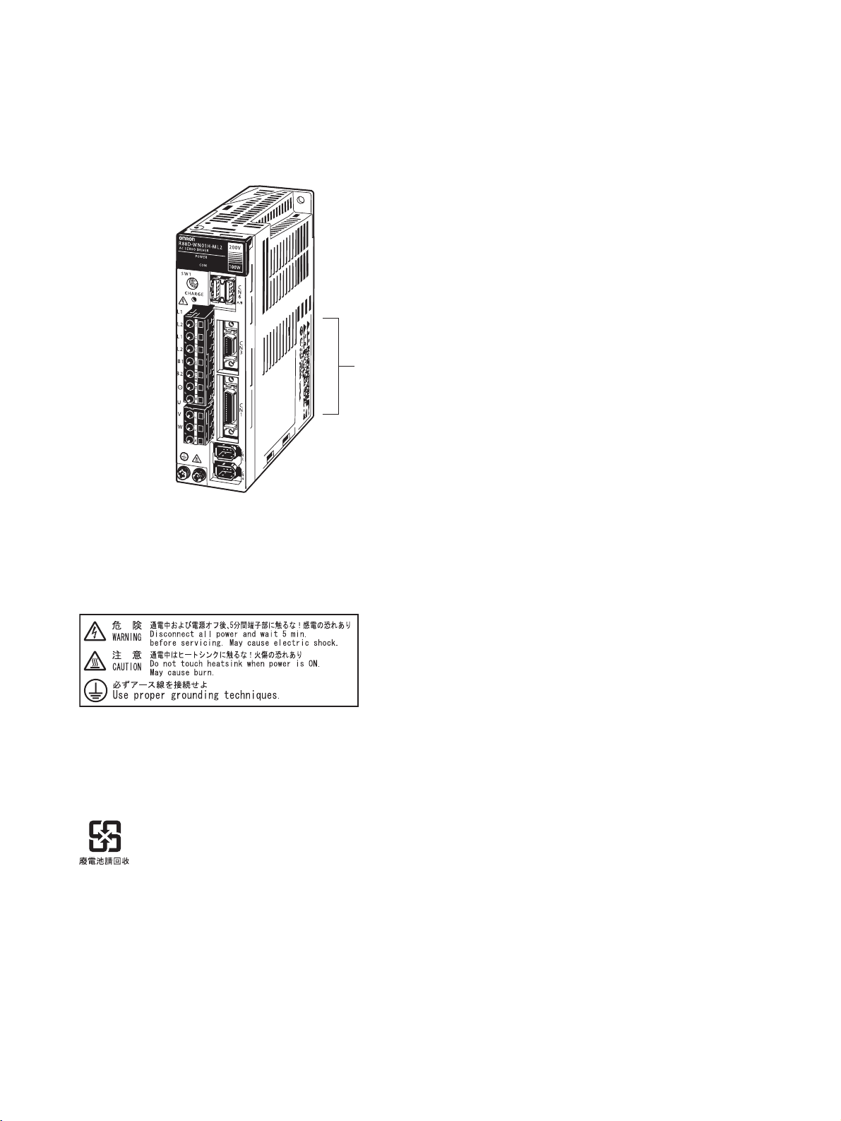
Warning Labels
Warning labels are pasted on the product as shown in the following illustration. Be sure to follow the
instructions given there.
Warning label
Precautions for Safe Use
Dispose of the product and batteries according to local ordinances as they apply.
Have qualified specialists properly dispose of used batteries as industrial waste.
Page 12

Page 13

Read and Understand this Manual
Please read and understand this manual before using the product. Please consult your OMRON
representative if you have any questions or comments.
Warranty and Limitations of Liability
WARRANTY
OMRON's exclusive warranty is that the products are free from defects in materials and workmanship for a
period of one year (or other period if specified) from date of sale by OMRON.
OMRON MAKES NO WARRANTY OR REPRESENTATION, EXPRESS OR IMPLIED, REGARDING NONINFRINGEMENT, MERCHANTABILITY, OR FITNESS FOR PARTICULAR PURPOSE OF THE
PRODUCTS. ANY BUYER OR USER ACKNOWLEDGES THAT THE BUYER OR USER ALONE HAS
DETERMINED THAT THE PRODUCTS WILL SUITABLY MEET THE REQUIREMENTS OF THEIR
INTENDED USE. OMRON DISCLAIMS ALL OTHER WARRANTIES, EXPRESS OR IMPLIED.
LIMITATIONS OF LIABILITY
OMRON SHALL NOT BE RESPONSIBLE FOR SPECIAL, INDIRECT, OR CONSEQUENTIAL DAMAGES,
LOSS OF PROFITS OR COMMERCIAL LOSS IN ANY WAY CONNECTED WITH THE PRODUCTS,
WHETHER SUCH CLAIM IS BASED ON CONTRACT, WARRANTY, NEGLIGENCE, OR STRICT
LIABILITY.
In no event shall the responsibility of OMRON for any act exceed the individual price of the product on which
liability is asserted.
IN NO EVENT SHALL OMRON BE RESPONSIBLE FOR WARRANTY, REPAIR, OR OTHER CLAIMS
REGARDING THE PRODUCTS UNLESS OMRON'S ANALYSIS CONFIRMS THAT THE PRODUCTS
WERE PROPERLY HANDLED, STORED, INSTALLED, AND MAINTAINED AND NOT SUBJECT TO
CONTAMINATION, ABUSE, MISUSE, OR INAPPROPRIATE MODIFICATION OR REPAIR.
Page 14

Application Considerations
SUITABILITY FOR USE
OMRON shall not be responsible for conformity with any standards, codes, or regulations that apply to the
combination of products in the customer's application or use of the products.
At the customer's request, OMRON will provide applicable third party certification documents identifying
ratings and limitations of use that apply to the products. This information by itself is not sufficient for a
complete determination of the suitability of the products in combination with the end product, machine,
system, or other application or use.
The following are some examples of applications for which particular attention must be given. This is not
intended to be an exhaustive list of all possible uses of the products, nor is it intended to imply that the uses
listed may be suitable for the products:
• Outdoor use, uses involving potential chemical contamination or electrical interference, or conditions or
uses not described in this manual.
• Nuclear energy control systems, combustion systems, railroad systems, aviation systems, medical
equipment, amusement machines, vehicles, safety equipment, and installations subject to separate
industry or government regulations.
• Systems, machines, and equipment that could present a risk to life or property.
Please know and observe all prohibitions of use applicable to the products.
NEVER USE THE PRODUCTS FOR AN APPLICATION INVOLVING SERIOUS RISK TO LIFE OR
PROPERTY WITHOUT ENSURING THAT THE SYSTEM AS A WHOLE HAS BEEN DESIGNED TO
ADDRESS THE RISKS, AND THAT THE OMRON PRODUCTS ARE PROPERLY RATED AND
INSTALLED FOR THE INTENDED USE WITHIN THE OVERALL EQUIPMENT OR SYSTEM.
PROGRAMMABLE PRODUCTS
OMRON shall not be responsible for the user's programming of a programmable product, or any
consequence thereof.
Page 15

Disclaimers
CHANGE IN SPECIFICATIONS
Product specifications and accessories may be changed at any time based on improvements and other
reasons.
It is our practice to change model numbers when published ratings or features are changed, or when
significant construction changes are made. However, some specifications of the products may be changed
without any notice. When in doubt, special model numbers may be assigned to fix or establish key
specifications for your application on your request. Please consult with your OMRON representative at any
time to confirm actual specifications of purchased products.
DIMENSIONS AND WEIGHTS
Dimensions and weights are nominal and are not to be used for manufacturing purposes, even when
tolerances are shown.
PERFORMANCE DATA
Performance data given in this manual is provided as a guide for the user in determining suitability and does
not constitute a warranty. It may represent the result of OMRON's test conditions, and the users must
correlate it to actual application requirements. Actual performance is subject to the OMRON Warranty and
Limitations of Liability.
ERRORS AND OMISSIONS
The information in this manual has been carefully checked and is believed to be accurate; however, no
responsibility is assumed for clerical, typographical, or proofreading errors, or omissions.
Page 16

Page 17

Table of Contents
Chapter 1. Introduction. . . . . . . . . . . . . . . . . . . . . . . . . . . . . . . . . . . . 1-1
1-1 Features. . . . . . . . . . . . . . . . . . . . . . . . . . . . . . . . . . . . . . . . . . . . . . . . . . . . . . . . . . . . . . . . . . 1-2
1-2 System Configuration. . . . . . . . . . . . . . . . . . . . . . . . . . . . . . . . . . . . . . . . . . . . . . . . . . . . . . . 1-4
1-3 Servo Driver Nomenclature . . . . . . . . . . . . . . . . . . . . . . . . . . . . . . . . . . . . . . . . . . . . . . . . . .1-5
1-4 Applicable Standards and Models . . . . . . . . . . . . . . . . . . . . . . . . . . . . . . . . . . . . . . . . . . . . . 1-6
1-5 System Block Diagrams . . . . . . . . . . . . . . . . . . . . . . . . . . . . . . . . . . . . . . . . . . . . . . . . . . . . .1-7
Chapter 2. Standard Models and Specifications. . . . . . . . . . . . . . . . 2-1
2-1 Standard Models. . . . . . . . . . . . . . . . . . . . . . . . . . . . . . . . . . . . . . . . . . . . . . . . . . . . . . . . . . . 2-2
2-2 Servo Driver and Servomotor Combinations . . . . . . . . . . . . . . . . . . . . . . . . . . . . . . . . . . . . . 2-16
2-3 External and Mounted Dimensions . . . . . . . . . . . . . . . . . . . . . . . . . . . . . . . . . . . . . . . . . . . . 2-18
2-4 Servo Driver Specifications . . . . . . . . . . . . . . . . . . . . . . . . . . . . . . . . . . . . . . . . . . . . . . . . . . 2-50
2-5 Servomotor Specifications . . . . . . . . . . . . . . . . . . . . . . . . . . . . . . . . . . . . . . . . . . . . . . . . . . . 2-71
2-6 Cable and Connector Specifications. . . . . . . . . . . . . . . . . . . . . . . . . . . . . . . . . . . . . . . . . . . . 2-93
2-7 External Regeneration Resistor Specifications. . . . . . . . . . . . . . . . . . . . . . . . . . . . . . . . . . . . 2-121
2-8 Absolute Encoder Backup Battery Specifications . . . . . . . . . . . . . . . . . . . . . . . . . . . . . . . . . 2-122
2-9 Reactor Specifications . . . . . . . . . . . . . . . . . . . . . . . . . . . . . . . . . . . . . . . . . . . . . . . . . . . . . . 2-124
2-10 MECHATROLINK-II Repeater Specifications . . . . . . . . . . . . . . . . . . . . . . . . . . . . . . . . . . . 2-126
Chapter 3. System Design and Installation . . . . . . . . . . . . . . . . . . . . 3-1
3-1 Installation Conditions . . . . . . . . . . . . . . . . . . . . . . . . . . . . . . . . . . . . . . . . . . . . . . . . . . . . . . 3-3
3-2 Wiring. . . . . . . . . . . . . . . . . . . . . . . . . . . . . . . . . . . . . . . . . . . . . . . . . . . . . . . . . . . . . . . . . . . 3-8
3-3 Regenerative Energy Absorption . . . . . . . . . . . . . . . . . . . . . . . . . . . . . . . . . . . . . . . . . . . . . . 3-32
3-4 Adjustments and Dynamic Braking When Load Inertia Is Large . . . . . . . . . . . . . . . . . . . . . 3-38
Chapter 4. Operation. . . . . . . . . . . . . . . . . . . . . . . . . . . . . . . . . . . . . . 4-1
4-1 Operational Procedure . . . . . . . . . . . . . . . . . . . . . . . . . . . . . . . . . . . . . . . . . . . . . . . . . . . . . . 4-3
4-2 Preparing for Operation . . . . . . . . . . . . . . . . . . . . . . . . . . . . . . . . . . . . . . . . . . . . . . . . . . . . . 4-4
4-3 User Parameters . . . . . . . . . . . . . . . . . . . . . . . . . . . . . . . . . . . . . . . . . . . . . . . . . . . . . . . . . . . 4-8
4-4 Operation Functions . . . . . . . . . . . . . . . . . . . . . . . . . . . . . . . . . . . . . . . . . . . . . . . . . . . . . . . . 4-75
4-5 Trial Operation Procedure . . . . . . . . . . . . . . . . . . . . . . . . . . . . . . . . . . . . . . . . . . . . . . . . . . . 4-96
4-6 Making Adjustments . . . . . . . . . . . . . . . . . . . . . . . . . . . . . . . . . . . . . . . . . . . . . . . . . . . . . . . 4-98
4-7 Advanced Adjustment Functions . . . . . . . . . . . . . . . . . . . . . . . . . . . . . . . . . . . . . . . . . . . . . . 4-103
4-8 Using Displays . . . . . . . . . . . . . . . . . . . . . . . . . . . . . . . . . . . . . . . . . . . . . . . . . . . . . . . . . . . . 4-130
4-9 Using Monitor Output . . . . . . . . . . . . . . . . . . . . . . . . . . . . . . . . . . . . . . . . . . . . . . . . . . . . . . 4-132
Chapter 5. Troubleshooting . . . . . . . . . . . . . . . . . . . . . . . . . . . . . . . . 5-1
5-1 Measures when Trouble Occurs . . . . . . . . . . . . . . . . . . . . . . . . . . . . . . . . . . . . . . . . . . . . . . . 5-2
5-2 Alarms . . . . . . . . . . . . . . . . . . . . . . . . . . . . . . . . . . . . . . . . . . . . . . . . . . . . . . . . . . . . . . . . . . 5-6
5-3 Troubleshooting . . . . . . . . . . . . . . . . . . . . . . . . . . . . . . . . . . . . . . . . . . . . . . . . . . . . . . . . . . . 5-12
5-4 Overload Characteristics (Electronic Thermal Characteristics) . . . . . . . . . . . . . . . . . . . . . . . 5-43
5-5 Periodic Maintenance . . . . . . . . . . . . . . . . . . . . . . . . . . . . . . . . . . . . . . . . . . . . . . . . . . . . . . . 5-45
5-6 Replacing the Absolute Encoder Battery (ABS) . . . . . . . . . . . . . . . . . . . . . . . . . . . . . . . . . . 5-47
Page 18

Table of Contents
Chapter 6. Appendix . . . . . . . . . . . . . . . . . . . . . . . . . . . . . . . . . . . . . . 6-1
6-1 Connection Examples . . . . . . . . . . . . . . . . . . . . . . . . . . . . . . . . . . . . . . . . . . . . . . . . . . . . . . . 6-2
6-2 Parameter Setting Tables. . . . . . . . . . . . . . . . . . . . . . . . . . . . . . . . . . . . . . . . . . . . . . . . . . . . . 6-3
6-3 Restrictions . . . . . . . . . . . . . . . . . . . . . . . . . . . . . . . . . . . . . . . . . . . . . . . . . . . . . . . . . . . . . . . 6-21
Index . . . . . . . . . . . . . . . . . . . . . . . . . . . . . . . . . . . . . . . . . . . . . . . . . . . I-1
Revision History . . . . . . . . . . . . . . . . . . . . . . . . . . . . . . . . . . . . . . . . . . R-1
Page 19

Chapter 1
Introduction
1-1 Features
1-2 System Configuration
1-3 Servo Driver Nomenclature
1-4 Applicable Standards and Models
1-5 System Block Diagrams
Page 20

Introduction
Chapter 1
1-1 Features
OMNUC W-series AC Servo Drivers with built-in MECHATROLINK-II Communications
are designed specifically for use with the MECHATROLINK-II high-speed motion field
network.
Combining these Servo Drivers with MECHATROLINK-II-compatible Motion Control
Units (CS1W-MCH71 or CJ1W-MCH71) or Position Control Units (CJ1W-NCF71) is an
easy way to create a high-speed servo control system with a communications link
between the Servo Drivers and the Controllers.
■ Data Transfer by MECHATROLINK-II Communications
When a Servo Driver is combined with a MECHATROLINK-II-compatible Motion Control Unit (CS1WMCH71 or CJ1W-MCH71) or Position Control Unit (CJ1W-NCF71), all control data is transferred
between the Servo Driver and the Controller by means of data communications.
Control commands are transferred by means of data communications, so Servomotor performance is
not limited by control interface specifications, such as response frequencies for input pulses and
encoder feedback pulses. This allows the Servomotor to perform to its fullest capacity.
Moreover, system data control is simplified by having all Servo Driver parameters and monitor data
managed by the host controller.
■ Built-in Communications Interface
The MECHATROLINK-II communications interface has been built into the Servo Driver. In comparison with earlier W-series Servo Drivers, in which the MECHATROLINK-II Application Module is
installed, only 60% of the installation surface area is required. (for 200-V/100-W Servo Drivers). This
allows a great saving of space in the control panel.
■ W-series Servomotor Compatibility
A W-series Servomotor can be used as is, including the encoder cable and power cable, so the system can be upgraded without changing the structural design.
The W-series product line offers 3,000-r/min Servomotors (Cylinder-style: 50-W to 3-kW; Flat-style:
100-W to 1.5-kw), 1,000-r/min Servomotors (300-W to 2-kW), and 1,500-r/min Servomotors (450-W
to 1.8-kW). Also, IP67 (waterproof) Servomotors can be connected in the same way.
■ High-speed, High-precision Motion Control Capability
A less-deviation control function and a predictive control function are provided to shorten the Servomotor's settling time and achieving high tracking capability.
The W-series Servomotors handle motion control with increased speed and precision, including synchronous control in combination with CS1W-MCH71 or CJ1W-MCH71 Motion Control Units.
1-2
Page 21

Introduction
■ Regenerative Power Processing
In addition to the built-in regenerative power processing function using regeneration resistance,
external regeneration resistance can also be connected, allowing the W Series to be used for applications with high regenerative energy on vertical axes.
■ Conformity to Standards
The W Series conforms to EC Directives (both low-voltage and EMC) as well as to UL and cUL
requirements, thereby assisting the user in meeting required standards.
■ High-frequency Current Countermeasures
On Servo Drivers of 1 kW and above, a current reactor connection terminal is provided to assist the
user in controlling high-frequency current.
Chapter 1
1-3
Page 22
Introduction
INC
ABS
Controller (MECHATROLINK-II Type)
Controller (MECHATROLINK-II Type)
MCH71
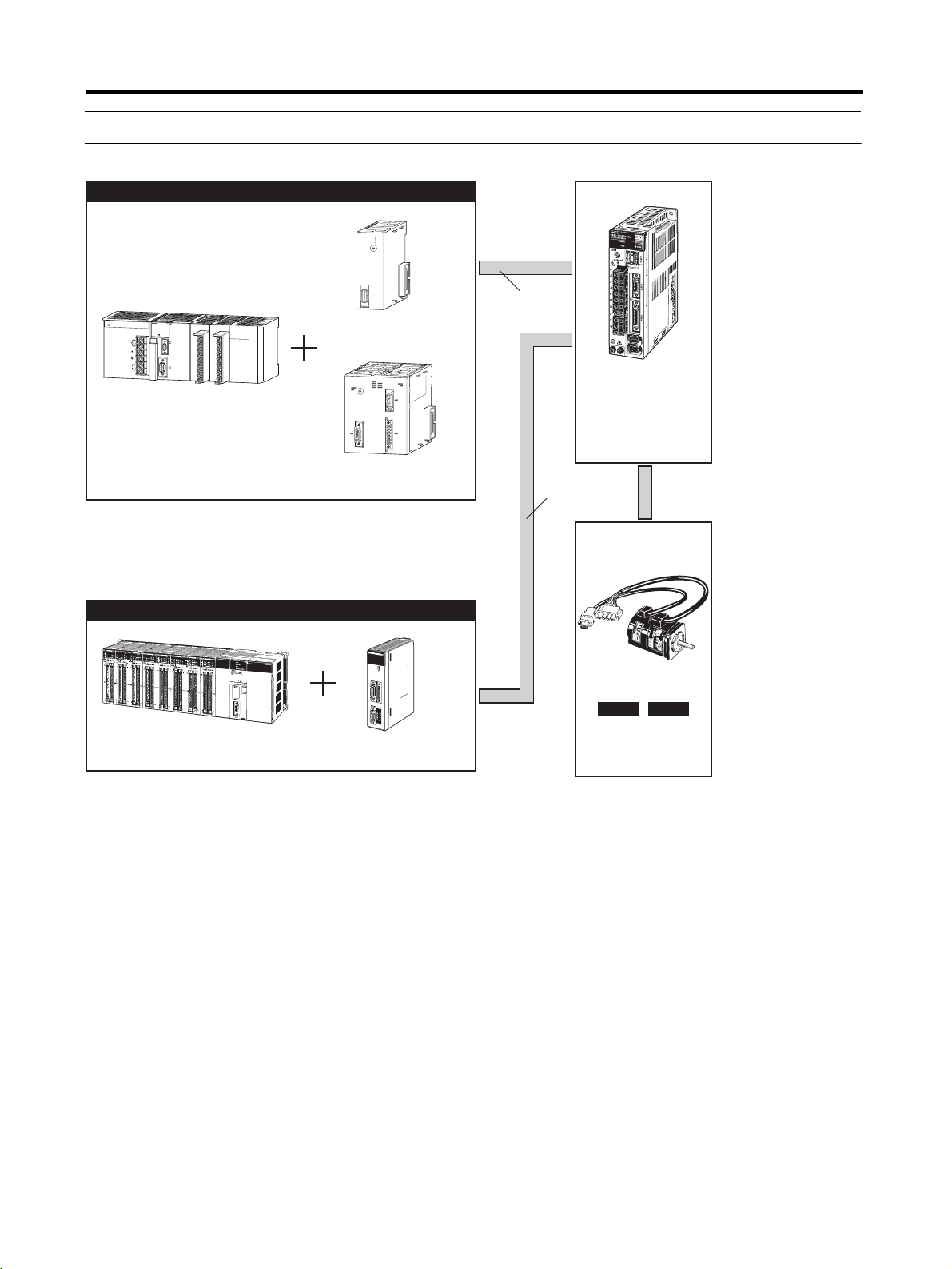
1-2 System Configuration
Controller (MECHATROLINK-II Type)
N
C
F
7
1
M
L
K
R
U
N
E
R
C
E
R
H
E
R
M
C
B
D
A
U
NIT
9
E
0
8
F
1
7
N
o.
2
6
3
5
4
M
LK
P
A
2
0
5
R
P
S
O
Y
W
E
R
SYSMAC CJ1
Programmable Controller
R
U
S
N
M
A
C
E
R
R
/
A
L
M
C
J
1
G
C
P
U
4
4
I
N
H
P
R
O
G
R
A
M
M
A
B
L
E
P
R
P
H
L
C
O
N
T
R
O
L
L
E
R
C
O
M
M
O
P
E
N
M
C
P
W
R
L
1
B
U
S
Y
A
C
1
0
0
2
4
0
V
I
N
P
U
T
L
2
/
N
P
ERI
PH
E
R
AL
R
U
N
O
U
T
P
U
T
A
C
2
4
0
V
D
C
2
4
V
P
O
R
T
CJ1W-NCF71
Position Control Unit
M
C
H
7
1
C
B
D
A
9
E
0
8
F
1
7
2
6
3
5
4
CJ1W-MCH71
Motion Control Unit
Chapter 1
MECHATRO
LINK-II
R88D-WN@@@-ML2
OMNUC W-series AC
Servo Driver with builtin MECHATROLINK-II
Communications
MECHATRO
LINK-II
Controller (MECHATROLINK-II Type)
SYSMAC CS1
Programmable Controller
M
C
H
7
1
R
U
N
E
R
C
E
R
H
E
R
1
E
R
3
E
R
2
E
R
4
S
S
I
M
L
K
U
N
I
T
N
o
.
T
.
B
.
S
S
I
I
/
O
M
L
K
CS1W-MCH71
Motion Control Unit
INC
ABS
R88M-W@
OMNUC W-series
AC Servomotor
1-4
Page 23
Introduction
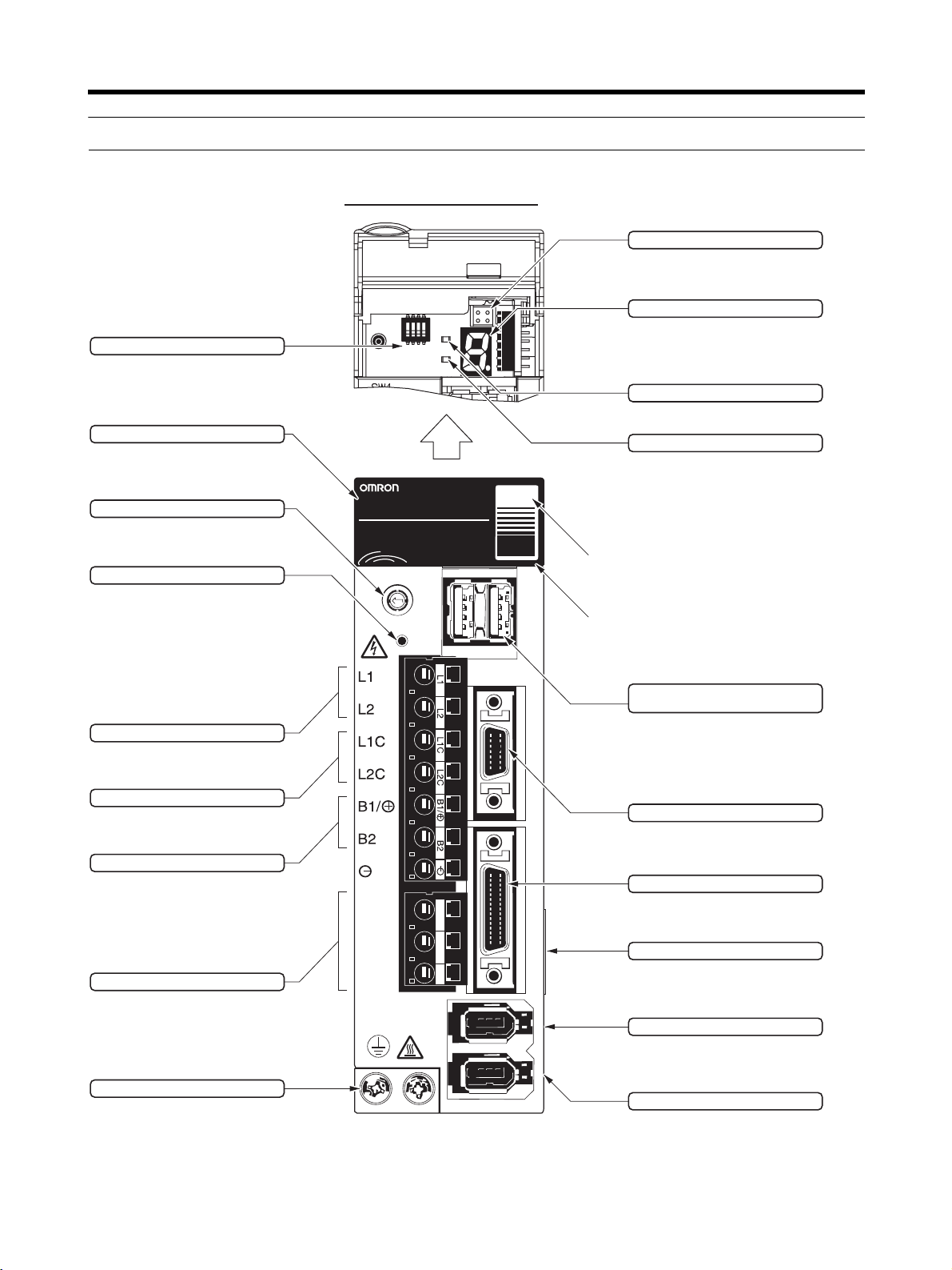
1-3 Servo Driver Nomenclature
With Top Cover Open
ON
SW1
4
3
2
1
0
F
E
CHARGE
1234
POWER
5
6
7
8
9
A
B
C
D
POWER
COM
COM
DIP Switch
Used for MECHATROLINK-II
communications settings.
Model Number
Rotary Switch (SW1)
Used for setting MECHATROLINK-II
node address.
Charge Indicator
Lit when the main-circuit is powered.
Also, for Servo Drivers of 1 kW or less,
the indicator lights dimly when only the
control power supply is ON. Even after
the power is turned OFF, it remains lit
as long as an electric charge remains in
the main-circuit capacitor, so do not
touch the Servo Driver's terminals
during this period.
Main-circuit Power Terminals
These are the input terminals for
the main-circuit power supply.
R88D-WN01H-ML2
AC SERVO DRIVER
200
100
W
V
A/B
Chapter 1
Analog Monitor Connector (CN5)
Motor rotation speeds, torque
command values, etc., can be
monitored using a special cable.
Panel Display
Displays Servomotor status with
a 7-segment LED display.
Power Indicator (POWER)
Lit when the control power is
being supplied.
Communications Indicator (COM)
Lit when MECHATROLINK-II
communications are in progress.
Input voltage
C
N
6
C
N
3
Top cover
MECHATROLINK-II Communications
Connectors (CN6A, CN6B)
Connect either a special cable for
a MECHATROLINK-II system or
a Terminating Resister.
Control Power Terminals
These are input terminals for the
control power supply.
Regenerative Resistance Terminals
These are terminals for external
regenerative resistance.
Servomotor Connector Terminals
These are connector terminals
for Servomotor power line.
Ground Terminals
These are ground terminals for
preventing electrical shock.
Connect to 100 Ω or less.
U
V
W
U V W
Personal Computer Connector (CN3)
This is the connector for
communications with a personal
computer.
C
N
1
I/O Signal Connector (CN1)
This is the connector for
command input signals and
sequence I/O signals.
Nameplate (Side Panel)
The nameplate shows the Servo
Driver model number and ratings.
C
N
2
C
N
4
Encoder Connector (CN2)
This is the connector for the
encoder provided for the
Servomotor.
Expansion Connector (CN4)
This is a supplementary
connector for future expansion. It
cannot presently be used, so do
not connect anything to it.
1-5
Page 24
Introduction
Chapter 1
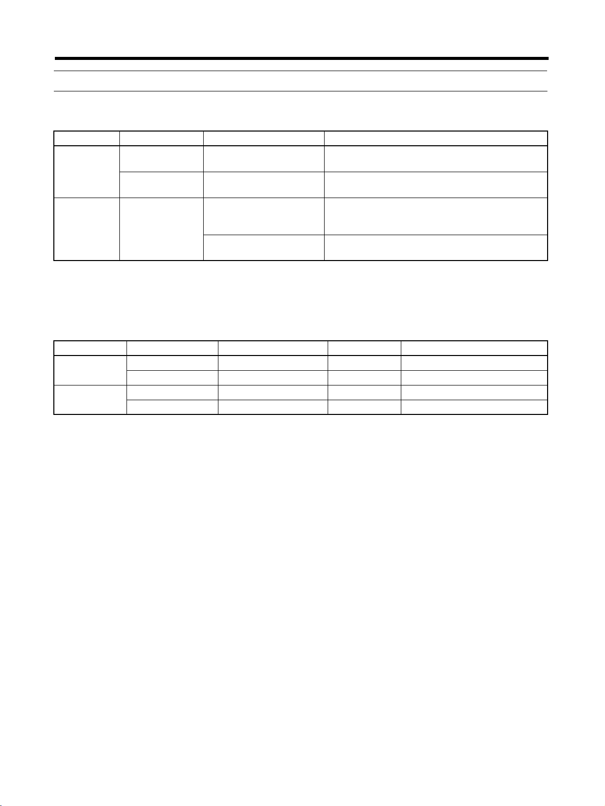
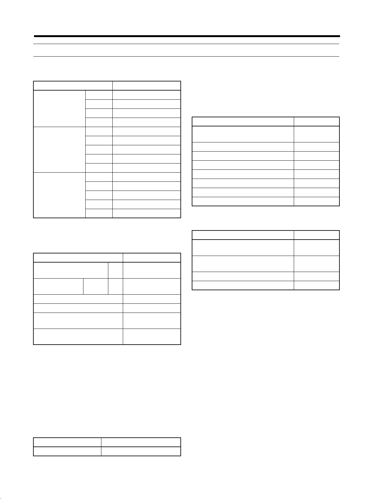
1-4 Applicable Standards and Models
■ EC Directives
EC Directive Product Applicable standard Remarks
Low Voltage AC Servo Drivers EN50178 Safety requirements for electrical equipment for
measurement, control, and laboratory use.
AC Servomotors IEC60034-8
EN60034-1, -5, -9
EMC AC Servo Drivers
and AC Servomotors
EN55011 class A group 1 Limits and methods for measuring radio distur-
EN61000-6-2 Electromagnetic compatibility generic immunity
Note Installation under the conditions specified in 3-2-5 Wiring for Conformity to EMC Directives is
required to conform to EMC Directives.
■ UL/cUL Standards
Rotating electrical machines.
bance characteristics of industrial, scientific, and
medical (ISM) radio-frequency equipment.
standard in industrial environments
Standards Product Applicable standard File No. Remarks
UL AC Servo Drivers UL508C E179149 Power conversion equipment
AC Servomotors UL1004 E179189 Electric motors
cUL AC Servo Drivers cUL C22.2 No. 14 E179149 Industrial control equipment
AC Servomotors cUL C22.2 No. 100 E179189 Motors and generators
1-6
Page 25
Introduction
r
Chapter 1
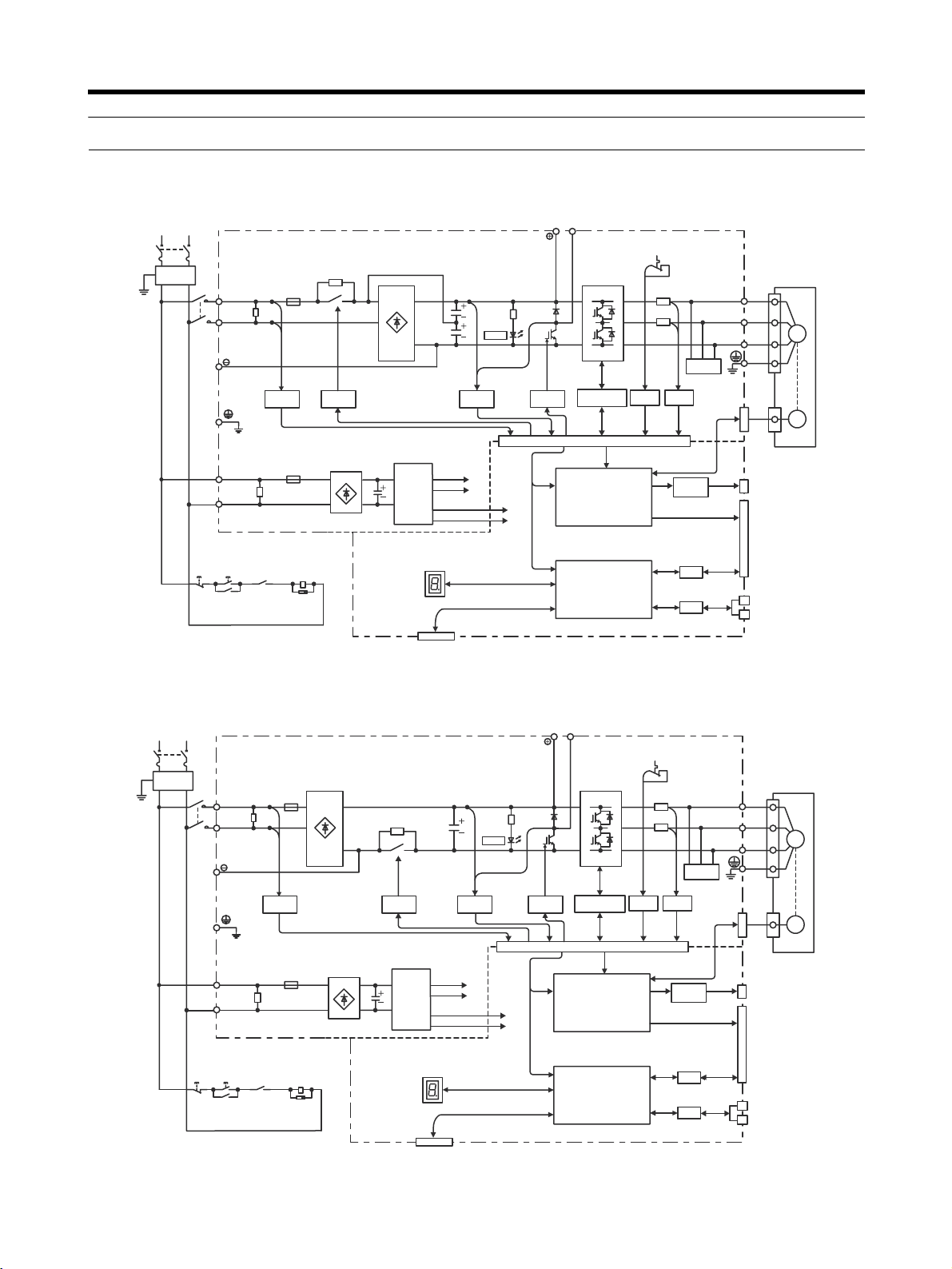
1-5 System Block Diagrams
■ 100 V AC: R88D-WNA5L-ML2/WN01L-ML2/-WL02L-ML2/-WN04L-ML2
Single-phase 100 to 115 V
+10%/−15% (50/60 Hz)
Noise
filter
1KM
L1
L2
L1C
L2C
Varistor
Varistor
Voltage
detection
Relay
drive
Control
power
supply
Voltage
detection
±5 V
15 V
B1/ B2
Servomotor
U
V
CH
AR
G
E
Gate
drive
Gate drive overcurrent protection
Temperature
detection
Current
detection
Dynamic
brake circuit
W
CN2
CN10
CN5
Analog voltage
conversion
CN1
5 V
±12 V
ASIC (PWM
control, etc.)
M
PG
Analog monitor
output
Encoder output
Power
Power
ON
1KM
Open for
servo alarm
1Ry
1KM
Surge
protector
Status indicator
CN3
Personal computer
CPU (position,
speed calculations,
etc.)
I/O
Control I/O
CN6A
I/F
CN6B
MECHATROLINK-II
OFF
■ 200 V AC: R88D-WNA5H-ML2/WN01H-ML2/-WL02H-ML2/-WN04H-ML2
Single-phase 200 to 230 V
+10%/−15% (50/60 Hz)
Noise
filter
1KM
L1
L2
L1C
L2C
Varistor
Voltage
detection
Varistor
Relay
drive
Control
power
supply
Voltage
detection
±5 V
15 V
C
HARG
E
5 V
±12 V
B1/ B2
Gate
drive
Gate drive overcurrent protection
CN10
ASIC (PWM
control, etc.)
Temperature
detection
Current
detection
Analog voltage
conversion
Dynamic
brake circuit
U
V
W
CN2
CN5
CN1
Servomoto
M
PG
Analog monitor
output
Encoder output
Power
OFF
Power
ON
1KM
Open for
servo alarm
1Ry
1KM
Surge
protector
Status indicator
CN3
Personal computer
CPU (position,
speed calculations,
etc.)
I/O
Control I/O
CN6A
I/F
CN6B
MECHATROLINK-II
1-7
Page 26
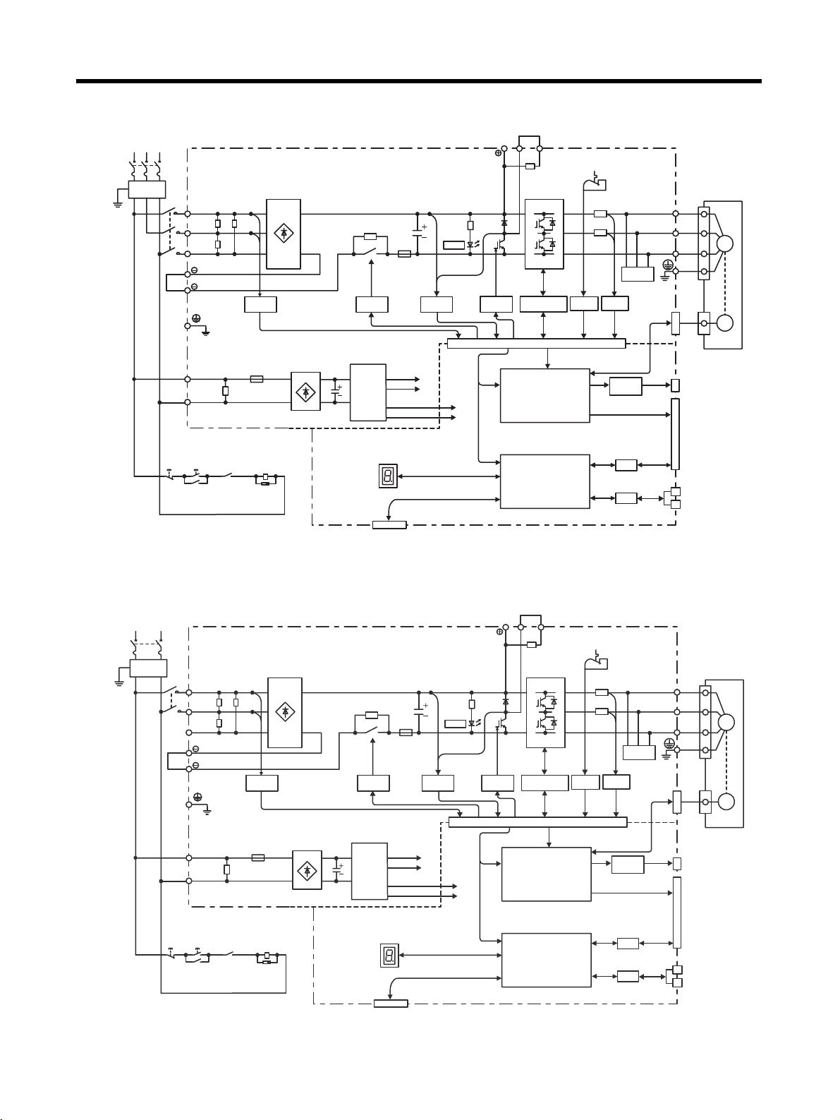
Introduction
p
■ 200 V AC: R88D-WN05H-ML2/WN10H-ML2
Three-phase 200 to 230 V
+10%/−15% (50/60 Hz)
Noise
filter
1KM
Power
OFF
L1
L2
L3
1
2
L1C
L2C
Power
ON
1KM
Varistor
Varistor
Open for
servo alarm
1Ry
Voltage
detection
1KM
Surge
protector
Relay
drive
Control
power
supply
Status indicator
Personal computer
CN3
Voltage
detection
±5 V
15 V
CHARGE
5 V
±12 V
B1/ B2 B3
Gate
Gate drive overcurrent protection
drive
CN10
CPU (position,
speed calculations,
etc.)
ASIC (PWM
control, etc.)
Temperature
detection
Current
detection
Analog voltage
conversion
Chapter 1
U
V
W
Dynamic
brake circuit
CN2
CN5
CN1
I/O
CN6A
I/F
CN6B
Servomotor
M
PG
Analog monitor
output
Encoder output
Control I/O
MECHATROLINK-II
■ 200 V AC: R88D-WN08H-ML2
Single-phase 200 to 230 V
+10%/−15% (50/60 Hz)
Noise
filter
1KM
Power
OFF
L1
L2
L3
L1C
L2C
Power
ON
1KM
1
2
Varistor
Varistor
Open for
servo alarm
1Ry
Voltage
detection
1KM
Surge
protector
Relay
drive
Control
power
supply
Status indicator
Personal com
CN3
uter
Voltage
detection
±5 V
15 V
CHARGE
5 V
±12 V
B1/ B2 B3
Gate
Gate drive overcurrent protection
drive
CN10
CPU (position,
speed calculations,
etc.)
ASIC (PWM
control, etc.)
Temperature
detection
Current
detection
Analog voltage
conversion
Dynamic
brake circuit
I/O
I/F
CN2
CN5
CN1
CN6A
CN6B
U
V
W
Analog monitor
output
Encoder output
Control I/O
MECHATROLINK-II
Servomotor
M
PG
1-8
Page 27
Introduction
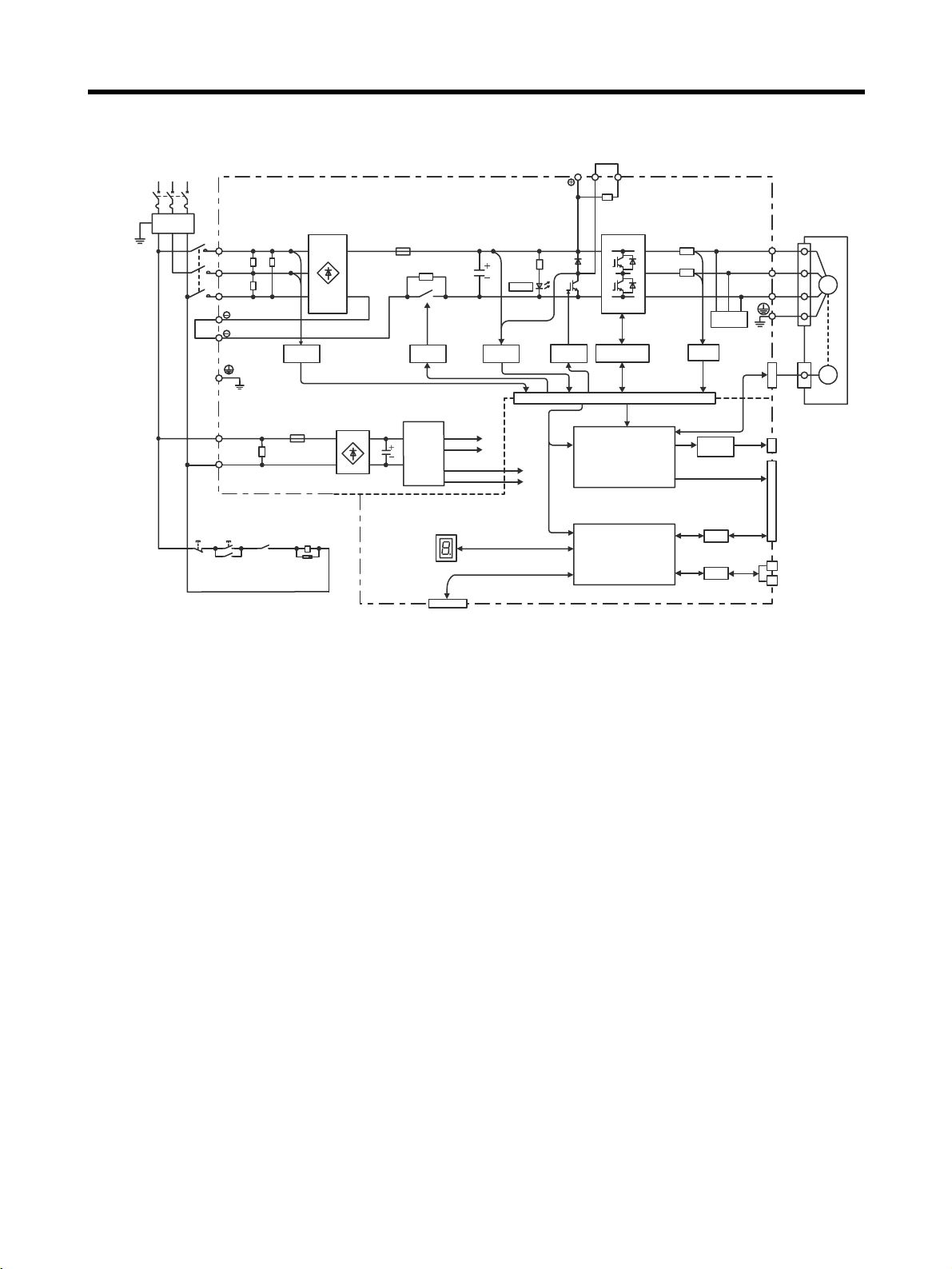
p
■ 200 V AC: R88D-WN15H-ML2/-WN20H-ML2/-WN30H-ML2
Three-phase 200 to 230 V
+10%/−15% (50/60 Hz)
B1/ B2 B3
Chapter 1
Noise
filter
1KM
Power
OFF
L1
L2
L3
L1C
L2C
Power
ON
1KM
1
2
Varistor
Varistor
Open for
servo alarm
1Ry
Voltage
detection
1KM
Surge
protector
Relay
drive
Control
power
supply
Status indicator
Personal com
CN3
uter
Voltage
detection
±5 V
15 V
CHARGE
5 V
±12 V
Gate
drive
CPU (position,
speed calculations,
etc.)
Gate drive overcurrent protection
CN10
ASIC (PWM
control, etc.)
Current
detection
Analog voltage
conversion
Dynamic
brake circuit
I/O
I/F
CN2
CN5
CN1
CN6A
CN6B
U
V
W
Analog monitor
output
Encoder output
Control I/O
MECHATROLINK-II
Servomotor
M
PG
1-9
Page 28

Introduction
Chapter 1
1-10
Page 29

Chapter 2
Standard Models and Specifications
2-1 Standard Models
2-2 Servo Driver and Servomotor Combinations
2-3 External and Mounted Dimensions
2-4 Servo Driver Specifications
2-5 Servomotor Specifications
2-6 Cable and Connector Specifications
2-7 External Regeneration Resistor Specifications
2-8 Absolute Encoder Backup Battery Specifications
2-9 Reactor Specifications
2-10 MECHATROLINK-II Repeater Specifications
Page 30
Standard Models and Specifications
2-1 Standard Models
Chapter 2
■ Servo Drivers
Specifications Model
Single-phase
100 V AC
Single-phase
200 V AC
Three-phase
200 V AC
■ Peripheral Cables and
50 W R88D-WNA5L-ML2
100 W R88D-WN01L-ML2
200 W R88D-WN02L-ML2
400 W R88D-WN04L-ML2
50 W R88D-WNA5H-ML2
100 W R88D-WN01H-ML2
200 W R88D-WN02H-ML2
400 W R88D-WN04H-ML2
750 W R88D-WN08H-ML2
500 W R88D-WN05H-ML2
1.0 kW R88D-WN10H-ML2
1.5 kW R88D-WN15H-ML2
2.0 kW R88D-WN20H-ML2
3.0 kW R88D-WN30H-ML2
Connectors
Specifications Model
Analog Monitor Cable
(CN5)
Computer Monitor Cable (CN3)
Control I/O Connector (CN1) R88A-CNW01C
Encoder Connector (CN2) R88A-CNW01R
Encoder Connector for Motor
End
Absolute Encoder Battery
Cable (with Battery)
DOS/V 2 m R88A-CCW002P2
1 m R88A-CMW001S
R88A-CNW02R
R88A-CRWC0R3C
Note Required when using a Servomotor with
an absolute encoder. The cable and connector are included.
■ Reactors
Specifications Model
For R88D-WNA5L-ML2/01L-ML2/
02H-ML2
For R88D-WN02L-ML2/04H-ML2 R88A-PX5054
For R88D-WN04L-ML2/08H-ML2 R88A-PX5056
For R88D-WNA5H-ML2/01H-ML2 R88A-PX5052
For R88D-WT04H-ML2 R88A-PX5069
For R88D-WN05H-ML2/10H-ML2 R88A-PX5061
For R88D-WN15H-ML2/20H-ML2 R88A-PX5060
For R88D-WN30H-ML2 R88A-PX5059
■ Front-panel Brackets
Specifications Model
For R88D-WNA5L-ML2 to 04LML2
For R88D-WNA5H-ML2 to 10HML2
For R88D-WN15H-ML2 R88A-TK06W
For R88D-WN20H-ML2/30H-ML2 R88A-TK07W
R88A-PX5053
R88A-TK05W
R88A-TK05W
Note Required when mounting a Servo Driver
from the front panel.
Note In order to use a personal computer to
monitor a Servo Driver and set its parameters, Computer Monitor Cable and Computer Monitor Software are required.
Please ask an OMRON representative for
details.
■ Absolute Encoder Backup
Battery
Specifications Model
1,000 mA·h, 3.6 V R88A-BAT01W
2-2
Page 31

Standard Models and Specifications
Chapter 2
■ Standard Encoder Cables (for
Incremental and Absolute
Encoders)
Specifications Model
For 3,000-r/
min Servomotors
For 3,000-r/
min Flat-style
Servomotors
For 1,000-r/
min Servomotors
For 1,500-r/
min Servomotors
30 to
750 W
1 to
3kW
100 W
to
1.5 kW
300 W
to
2.0 kW
450 W
to
1.8 kW
3 m R88A-CRWA003C
5 m R88A-CRWA005C
10 m R88A-CRWA010C
15 m R88A-CRWA015C
20 m R88A-CRWA020C
30 m R88A-CRWA030C
40 m R88A-CRWA040C
50 m R88A-CRWA050C
3 m R88A-CRWB003N
5 m R88A-CRWB005N
10 m R88A-CRWB010N
15 m R88A-CRWB015N
20 m R88A-CRWB020N
30 m R88A-CRWB030N
40 m R88A-CRWB040N
50 m R88A-CRWB050N
3 m R88A-CRWA003C
5 m R88A-CRWA005C
10 m R88A-CRWA010C
15 m R88A-CRWA015C
20 m R88A-CRWA020C
30 m R88A-CRWA030C
40 m R88A-CRWA040C
50 m R88A-CRWA050C
3 m R88A-CRWB003N
5 m R88A-CRWB005N
10 m R88A-CRWB010N
15 m R88A-CRWB015N
20 m R88A-CRWB020N
30 m R88A-CRWB030N
40 m R88A-CRWB040N
50 m R88A-CRWB050N
■ Standard Power Cable
● Power Cable for 3,000-r/min
Servomotors
Specifications Model
Without brake With brake
30 to
750 W
1 to
2kW
3 kW 3 m R88A-CAWD003S R88A-CAWD003B
● Power Cable for 3,000-r/min Flat-style
3 m R88A-CAWA003S R88A-CAWA003B
5 m R88A-CAWA005S R88A-CAWA005B
10 m R88A-CAWA010S R88A-CAWA010B
15 m R88A-CAWA015S R88A-CAWA015B
20 m R88A-CAWA020S R88A-CAWA020B
30 m R88A-CAWA030S R88A-CAWA030B
40 m R88A-CAWA040S R88A-CAWA040B
50 m R88A-CAWA050S R88A-CAWA050B
3 m R88A-CAWC003S R88A-CAWC003B
5 m R88A-CAWC005S R88A-CAWC005B
10 m R88A-CAWC010S R88A-CAWC010B
15 m R88A-CAWC015S R88A-CAWC015B
20 m R88A-CAWC020S R88A-CAWC020B
30 m R88A-CAWC030S R88A-CAWC030B
40 m R88A-CAWC040S R88A-CAWC040B
50 m R88A-CAWC050S R88A-CAWC050B
5 m R88A-CAWD005S R88A-CAWD005B
10 m R88A-CAWD010S R88A-CAWD010B
15 m R88A-CAWD015S R88A-CAWD015B
20 m R88A-CAWD020S R88A-CAWD020B
30 m R88A-CAWD030S R88A-CAWD030B
40 m R88A-CAWD040S R88A-CAWD040B
50 m R88A-CAWD050S R88A-CAWD050B
Servomotors
Specifications Model
Without brake With brake
100 to
750 W
3 m R88A-CAWA003S R88A-CAWA003B
5 m R88A-CAWA005S R88A-CAWA005B
10 m R88A-CAWA010S R88A-CAWA010B
15 m R88A-CAWA015S R88A-CAWA015B
20 m R88A-CAWA020S R88A-CAWA020B
30 m R88A-CAWA030S R88A-CAWA030B
40 m R88A-CAWA040S R88A-CAWA040B
50 m R88A-CAWA050S R88A-CAWA050B
2-3
Page 32

Standard Models and Specifications
Chapter 2
Specifications Model
Without brake With brake
1.5 kW 3 m R88A-CAWB003S R88A-CAWB003B
5 m R88A-CAWB005S R88A-CAWB005B
10 m R88A-CAWB010S R88A-CAWB010B
15 m R88A-CAWB015S R88A-CAWB015B
20 m R88A-CAWB020S R88A-CAWB020B
30 m R88A-CAWB030S R88A-CAWB030B
40 m R88A-CAWB040S R88A-CAWB040B
50 m R88A-CAWB050S R88A-CAWB050B
● Power Cable for 1,000-r/min
Servomotors
Specifications Model
Without brake With brake
300 to
900 W
1.2 to
2kW
3 m R88A-CAWC003S R88A-CAWC003B
5 m R88A-CAWC005S R88A-CAWC005B
10 m R88A-CAWC010S R88A-CAWC010B
15 m R88A-CAWC015S R88A-CAWC015B
20 m R88A-CAWC020S R88A-CAWC020B
30 m R88A-CAWC030S R88A-CAWC030B
40 m R88A-CAWC040S R88A-CAWC040B
50 m R88A-CAWC050S R88A-CAWC050B
3 m R88A-CAWD003S R88A-CAWD003B
5 m R88A-CAWD005S R88A-CAWD005B
10 m R88A-CAWD010S R88A-CAWD010B
15 m R88A-CAWD015S R88A-CAWD015B
20 m R88A-CAWD020S R88A-CAWD020B
30 m R88A-CAWD030S R88A-CAWD030B
40 m R88A-CAWD040S R88A-CAWD040B
50 m R88A-CAWD050S R88A-CAWD050B
● Power Cable for 1,500-r/min
Servomotors
Specifications Model
Without brake With brake
450 to
1.3 kW
1.8 kW 3 m R88A-CAWD003S R88A-CAWD003B
3 m R88A-CAWC003S R88A-CAWC003B
5 m R88A-CAWC005S R88A-CAWC005B
10 m R88A-CAWC010S R88A-CAWC010B
15 m R88A-CAWC015S R88A-CAWC015B
20 m R88A-CAWC020S R88A-CAWC020B
30 m R88A-CAWC030S R88A-CAWC030B
40 m R88A-CAWC040S R88A-CAWC040B
50 m R88A-CAWC050S R88A-CAWC050B
5 m R88A-CAWD005S R88A-CAWD005B
10 m R88A-CAWD010S R88A-CAWD010B
15 m R88A-CAWD015S R88A-CAWD015B
20 m R88A-CAWD020S R88A-CAWD020B
30 m R88A-CAWD030S R88A-CAWD030B
40 m R88A-CAWD040S R88A-CAWD040B
50 m R88A-CAWD050S R88A-CAWD050B
■ Encoder Cables for Robot
Cables (for Incremental and
Absolute Encoders)
Specifications Model
For 3,000-r/
min Servomotors
30 to
750 W
1 to
3kW
3 m R88A-CRWA003CR
5 m R88A-CRWA005CR
10 m R88A-CRWA010CR
15 m R88A-CRWA015CR
20 m R88A-CRWA020CR
30 m R88A-CRWA030CR
40 m R88A-CRWA040CR
50 m R88A-CRWA050CR
3 m R88A-CRWB003NR
5 m R88A-CRWB005NR
10 m R88A-CRWB010NR
15 m R88A-CRWB015NR
20 m R88A-CRWB020NR
30 m R88A-CRWB030NR
40 m R88A-CRWB040NR
50 m R88A-CRWB050NR
2-4
Page 33

Standard Models and Specifications
Chapter 2
Specifications Model
For 3,000-r/
min Flat-style
Servomotors
100 W
to
1.5 kW
3 m R88A-CRWA003CR
5 m R88A-CRWA005CR
10 m R88A-CRWA010CR
15 m R88A-CRWA015CR
20 m R88A-CRWA020CR
30 m R88A-CRWA030CR
40 m R88A-CRWA040CR
50 m R88A-CRWA050CR
For 1,000-r/
min Servomotors
For 1,500-r/
min Servomotors
300 W
to
2.0 kW
450 W
to
1.8 kW
3 m R88A-CRWB003NR
5 m R88A-CRWB005NR
10 m R88A-CRWB010NR
15 m R88A-CRWB015NR
20 m R88A-CRWB020NR
30 m R88A-CRWB030NR
40 m R88A-CRWB040NR
50 m R88A-CRWB050NR
■ Power Cable for Robot Cables
● Power Cable for 3,000-r/min
Servomotors
Specifications Model
Without brake With brake
30 to
750 W
1 to
2kW
3 m R88A-CAWA003SR R88A-CAWA003BR
5 m R88A-CAWA005SR R88A-CAWA005BR
10 m R88A-CAWA010SR R88A-CAWA010BR
15 m R88A-CAWA015SR R88A-CAWA015BR
20 m R88A-CAWA020SR R88A-CAWA020BR
30 m R88A-CAWA030SR R88A-CAWA030BR
40 m R88A-CAWA040SR R88A-CAWA040BR
50 m R88A-CAWA050SR R88A-CAWA050BR
3 m R88A-CAWC003SR R88A-CAWC003BR
5 m R88A-CAWC005SR R88A-CAWC005BR
10 m R88A-CAWC010SR R88A-CAWC010BR
15 m R88A-CAWC015SR R88A-CAWC015BR
20 m R88A-CAWC020SR R88A-CAWC020BR
30 m R88A-CAWC030SR R88A-CAWC030BR
40 m R88A-CAWC040SR R88A-CAWC040BR
50 m R88A-CAWC050SR R88A-CAWC050BR
Specifications Model
Without brake With brake
3 kW 3 m R88A-CAWD003SR R88A-CAWD003BR
5 m R88A-CAWD005SR R88A-CAWD005BR
10 m R88A-CAWD010SR R88A-CAWD010BR
15 m R88A-CAWD015SR R88A-CAWD015BR
20 m R88A-CAWD020SR R88A-CAWD020BR
30 m R88A-CAWD030SR R88A-CAWD030BR
40 m R88A-CAWD040SR R88A-CAWD040BR
50 m R88A-CAWD050SR R88A-CAWD050BR
● Power Cable for 3,000-r/min Flat-style
Servomotors
Specifications Model
Without brake With brake
100 to
750 W
1.5 kW 3 m R88A-CAWB003SR R88A-CAWB003BR
● Power Cable for 1,000-r/min
3 m R88A-CAWA003SR R88A-CAWA003BR
5 m R88A-CAWA005SR R88A-CAWA005BR
10 m R88A-CAWA010SR R88A-CAWA010BR
15 m R88A-CAWA015SR R88A-CAWA015BR
20 m R88A-CAWA020SR R88A-CAWA020BR
30 m R88A-CAWA030SR R88A-CAWA030BR
40 m R88A-CAWA040SR R88A-CAWA040BR
50 m R88A-CAWA050SR R88A-CAWA050BR
5 m R88A-CAWB005SR R88A-CAWB005BR
10 m R88A-CAWB010SR R88A-CAWB010BR
15 m R88A-CAWB015SR R88A-CAWB015BR
20 m R88A-CAWB020SR R88A-CAWB020BR
30 m R88A-CAWB030SR R88A-CAWB030BR
40 m R88A-CAWB040SR R88A-CAWB040BR
50 m R88A-CAWB050SR R88A-CAWB050BR
Servomotors
Specifications Model
Without brake With brake
300 to
900 W
3 m R88A-CAWC003SR R88A-CAWC003BR
5 m R88A-CAWC005SR R88A-CAWC005BR
10 m R88A-CAWC010SR R88A-CAWC010BR
15 m R88A-CAWC015SR R88A-CAWC015BR
20 m R88A-CAWC020SR R88A-CAWC020BR
30 m R88A-CAWC030SR R88A-CAWC030BR
40 m R88A-CAWC040SR R88A-CAWC040BR
50 m R88A-CAWC050SR R88A-CAWC050BR
2-5
Page 34

Standard Models and Specifications
Specifications Model
Without brake With brake
1.2 to
2kW
● Power Cable for 1,500-r/min
Servomotors
Specifications Model
450 to
1.3 kW
1.8 kW 3 m R88A-CAWD003SR R88A-CAWD003BR
3 m R88A-CAWD003SR R88A-CAWD003BR
5 m R88A-CAWD005SR R88A-CAWD005BR
10 m R88A-CAWD010SR R88A-CAWD010BR
15 m R88A-CAWD015SR R88A-CAWD015BR
20 m R88A-CAWD020SR R88A-CAWD020BR
30 m R88A-CAWD030SR R88A-CAWD030BR
40 m R88A-CAWD040SR R88A-CAWD040BR
50 m R88A-CAWD050SR R88A-CAWD050BR
Without brake With brake
3 m R88A-CAWC003SR R88A-CAWC003BR
5 m R88A-CAWC005SR R88A-CAWC005BR
10 m R88A-CAWC010SR R88A-CAWC010BR
15 m R88A-CAWC015SR R88A-CAWC015BR
20 m R88A-CAWC020SR R88A-CAWC020BR
30 m R88A-CAWC030SR R88A-CAWC030BR
40 m R88A-CAWC040SR R88A-CAWC040BR
50 m R88A-CAWC050SR R88A-CAWC050BR
5 m R88A-CAWD005SR R88A-CAWD005BR
10 m R88A-CAWD010SR R88A-CAWD010BR
15 m R88A-CAWD015SR R88A-CAWD015BR
20 m R88A-CAWD020SR R88A-CAWD020BR
30 m R88A-CAWD030SR R88A-CAWD030BR
40 m R88A-CAWD040SR R88A-CAWD040BR
50 m R88A-CAWD050SR R88A-CAWD050BR
Chapter 2
2-6
Page 35

Standard Models and Specifications
■ Servomotors
Specifications Model
With incremental encoder With absolute encoder
Straight shaft without
key
● 3,000-r/min Servomotors
Without
brake
With
brake
200 V 50 W R88M-W05030H R88M-W05030H-S1 R88M-W05030T R88M-W05030T-S1
100 W R88M-W10030H R88M-W10030H-S1 R88M-W10030T R88M-W10030T-S1
200 W R88M-W20030H R88M-W20030H-S1 R88M-W20030T R88M-W20030T-S1
400 W R88M-W40030H R88M-W40030H-S1 R88M-W40030T R88M-W40030T-S1
750 W R88M-W75030H R88M-W75030H-S1 R88M-W75030T R88M-W75030T-S1
1 kW R88M-W1K030H R88M-W1K030H-S2 R88M-W1K030T R88M-W1K030T-S2
1.5 kW R88M-W1K530H R88M-W1K530H-S2 R88M-W1K530T R88M-W1K530T-S2
2 kW R88M-W2K030H R88M-W2K030H-S2 R88M-W2K030T R88M-W2K030T-S2
3 kW R88M-W3K030H R88M-W3K030H-S2 R88M-W3K030T R88M-W3K030T-S2
200 V 50 W R88M-W05030H-B R88M-W05030H-BS1 R88M-W05030T-B R88M-W05030T-BS1
100 W R88M-W10030H-B R88M-W10030H-BS1 R88M-W10030T-B R88M-W10030T-BS1
200 W R88M-W20030H-B R88M-W20030H-BS1 R88M-W20030T-B R88M-W20030T-BS1
400 W R88M-W40030H-B R88M-W40030H-BS1 R88M-W40030T-B R88M-W40030T-BS1
750 W R88M-W75030H-B R88M-W75030H-BS1 R88M-W75030T-B R88M-W75030T-BS1
1 kW R88M-W1K030H-B R88M-W1K030H-BS2 R88M-W1K030T-B R88M-W1K030T-BS2
1.5 kW R88M-W1K530H-B R88M-W1K530H-BS2 R88M-W1K530T-B R88M-W1K530T-BS2
2 kW R88M-W2K030H-B R88M-W2K030H-BS2 R88M-W2K030T-B R88M-W2K030T-BS2
3 kW R88M-W3K030H-B R88M-W3K030H-BS2 R88M-W3K030T-B R88M-W3K030T-BS2
Straight shaft with key Straight shaft without
Chapter 2
Straight shaft with key
key
● 3,000-r/min Flat-style Servomotors
Without
brake
With
brake
200 V 100 W R88M-WP10030H R88M-WP10030H-S1 R88M-WP10030T R88M-WP10030T-S1
200 W R88M-WP20030H R88M-WP20030H-S1 R88M-WP20030T R88M-WP20030T-S1
400 W R88M-WP40030H R88M-WP40030H-S1 R88M-WP40030T R88M-WP40030T-S1
750 W R88M-WP75030H R88M-WP75030H-S1 R88M-WP75030T R88M-WP75030T-S1
1.5 kW R88M-WP1K530H R88M-WP1K530H-S1 R88M-WP1K530T R88M-WP1K530T-S1
200 V 100 W R88M-WP10030H-B R88M-WP10030H-BS1 R88M-WP10030T-B R88M-WP10030T-BS1
200 W R88M-WP20030H-B R88M-WP20030H-BS1 R88M-WP20030T-B R88M-WP20030T-BS1
400 W R88M-WP40030H-B R88M-WP40030H-BS1 R88M-WP40030T-B R88M-WP40030T-BS1
750 W R88M-WP75030H-B R88M-WP75030H-BS1 R88M-WP75030T-B R88M-WP75030T-BS1
1.5 kW R88M-WP1K530H-B R88M-WP1K530H-BS1 R88M-WP1K530T-B R88M-WP1K530T-BS1
● 1,000-r/min Servomotors
Without
brake
With
brake
200 V 300 W R88M-W30010H R88M-W30010H-S2 R88M-W30010T R88M-W30010T-S2
600 W R88M-W60010H R88M-W60010H-S2 R88M-W60010T R88M-W60010T-S2
900 W R88M-W90010H R88M-W90010H-S2 R88M-W90010T R88M-W90010T-S2
1.2 kW R88M-W1K210H R88M-W1K210H-S2 R88M-W1K210T R88M-W1K210T-S2
2 kW R88M-W2K010H R88M-W2K010H-S2 R88M-W2K010T R88M-W2K010T-S2
200 V 300 W R88M-W30010H-B R88M-W30010H-BS2 R88M-W30010T-B R88M-W30010T-BS2
600 W R88M-W60010H-B R88M-W60010H-BS2 R88M-W60010T-B R88M-W60010T-BS2
900 W R88M-W90010H-B R88M-W90010H-BS2 R88M-W90010T-B R88M-W90010T-BS2
1.2 kW R88M-W1K210H-B R88M-W1K210H-BS2 R88M-W1K210T-B R88M-W1K210T-BS2
2 kW R88M-W2K010H-B R88M-W2K010H-BS2 R88M-W2K010T-B R88M-W2K010T-BS2
2-7
Page 36

Standard Models and Specifications
● 1,500-r/min Servomotors
Without
brake
With
brake
■ IP67 (Waterproof) Servomotors
● 3,000-r/min Servomotors
Without
brake
With
brake
200 V 450 W --- --- R88M-W45015T R88M-W45015T-S2
850 W --- --- R88M-W85015T R88M-W85015T-S2
1.3 kW --- --- R88M-W1K315T R88M-W1K315T-S2
1.8 kW --- --- R88M-W1K815T R88M-W1K815T-S2
200 V 450 W --- --- R88M-W45015T-B R88M-W45015T-BS2
850 W --- --- R88M-W85015T-B R88M-W85015T-BS2
1.3 kW --- --- R88M-W1K315T-B R88M-W1K315T-BS2
1.8 kW --- --- R88M-W1K815T-B R88M-W1K815T-BS2
Specifications Model
With incremental encoder With absolute encoder
Straight shaft without
key
200 V 1 kW R88M-W1K030H-O R88M-W1K030H-OS2 R88M-W1K030T-O R88M-W1K030T-OS2
1.5 kW R88M-W1K530H-O R88M-W1K530H-OS2 R88M-W1K530T-O R88M-W1K530T-OS2
2 kW R88M-W2K030H-O R88M-W2K030H-OS2 R88M-W2K030T-O R88M-W2K030T-OS2
3 kW R88M-W3K030H-O R88M-W3K030H-OS2 R88M-W3K030T-O R88M-W3K030T-OS2
200 V 1 kW R88M-W1K030H-BO R88M-W1K030H-BOS2 R88M-W1K030T-BO R88M-W1K030T-BOS2
1.5 kW R88M-W1K530H-BO R88M-W1K530H-BOS2 R88M-W1K530T-BO R88M-W1K530T-BOS2
2 kW R88M-W2K030H-BO R88M-W2K030H-BOS2 R88M-W2K030T-BO R88M-W2K030T-BOS2
3 kW R88M-W3K030H-BO R88M-W3K030H-BOS2 R88M-W3K030T-BO R88M-W3K030T-BOS2
Straight shaft with key Straight shaft without
Chapter 2
Straight shaft with key
key
● 3,000-r/min Flat-style Servomotors
Without
brake
With
brake
200 V 100 W R88M-WP10030H-W R88M-WP10030H-WS1 R88M-WP10030T-W R88M-WP10030T-WS1
200 W R88M-WP20030H-W R88M-WP20030H-WS1 R88M-WP20030T-W R88M-WP20030T-WS1
400 W R88M-WP40030H-W R88M-WP40030H-WS1 R88M-WP40030T-W R88M-WP40030T-WS1
750 W R88M-WP75030H-W R88M-WP75030H-WS1 R88M-WP75030T-W R88M-WP75030T-WS1
1.5 kW R88M-WP1K530H-W R88M-WP1K530H-WS1 R88M-WP1K530T-W R88M-WP1K530T-WS1
200 V 100 W R88M-WP10030H-BW R88M-WP10030H-BWS1 R88M-WP10030T-BW R88M-WP10030T-BWS1
200 W R88M-WP20030H-BW R88M-WP20030H-BWS1 R88M-WP20030T-BW R88M-WP20030T-BWS1
400 W R88M-WP40030H-BW R88M-WP40030H-BWS1 R88M-WP40030T-BW R88M-WP40030T-BWS1
750 W R88M-WP75030H-BW R88M-WP75030H-BWS1 R88M-WP75030T-BW R88M-WP75030T-BWS1
1.5 kW R88M-WP1K530H-BW R88M-WP1K530H-BWS1 R88M-WP1K530T-BW R88M-WP1K530T-BWS1
● 1,000-r/min Servomotors
Without
brake
With
brake
200 V 300 W R88M-W30010H-O R88M-W30010H-OS2 R88M-W30010T-O R88M-W30010T-OS2
600 W R88M-W60010H-O R88M-W60010H-OS2 R88M-W60010T-O R88M-W60010T-OS2
900 W R88M-W90010H-O R88M-W90010H-OS2 R88M-W90010T-O R88M-W90010T-OS2
1.2 kW R88M-W1K210H-O R88M-W1K210H-OS2 R88M-W1K210T-O R88M-W1K210T-OS2
2 kW R88M-W2K010H-O R88M-W2K010H-OS2 R88M-W2K010T-O R88M-W2K010T-OS2
200 V 300 W R88M-W30010H-BO R88M-W30010H-BOS2 R88M-W30010T-BO R88M-W30010T-BOS2
600 W R88M-W60010H-BO R88M-W60010H-BOS2 R88M-W60010T-BO R88M-W60010T-BOS2
900 W R88M-W90010H-BO R88M-W90010H-BOS2 R88M-W90010T-BO R88M-W90010T-BOS2
1.2 kW R88M-W1K210H-BO R88M-W1K210H-BOS2 R88M-W1K210T-BO R88M-W1K210T-BOS2
2 kW R88M-W2K010H-BO R88M-W2K010H-BOS2 R88M-W2K010T-BO R88M-W2K010T-BOS2
2-8
Page 37

Standard Models and Specifications
● 1,500-r/min Servomotors
Without
brake
With
brake
200 V 450 W --- --- R88M-W45015TO R88M-W45015T-OS2
850 W --- --- R88M-W85015TO R88M-W85015T-OS2
1.3 kW --- --- R88M-W1K315TO R88M-W1K315T-OS2
1.8 kW --- --- R88M-W1K815TO R88M-W1K815T-OS2
200 V 450 W --- --- R88M-W45015T-BO R88M-W45015T-BOS2
850 W --- --- R88M-W85015T-BO R88M-W85015T-BOS2
1.3 kW --- --- R88M-W1K315T-BO R88M-W1K315T-BOS2
1.8 kW --- --- R88M-W1K815T-BO R88M-W1K815T-BOS2
Chapter 2
■ Servomotors with Gears
● Combination Table for Servomotors with Standard Gears
Standard Gears are highly accurate gears, with a maximum backlash of 3 degrees. The standard
shaft is a straight shaft with a key. (Models without keys can also be manufactured for 3,000-r/min
motors from 30 to 750 W and for 3,000-r/min flat-style motors. Models without keys have a suffix of G@@B.)
Note A check mark in a box indicates that the two models can be combined. If the box is unchecked,
then the models cannot be combined.
3,000-r/min Servomotors
Specifications Basic model Gear (deceleration rate)
1/5 1/9 1/11 1/20 1/21 1/29 1/33 1/45
-G05BJ -G09BJ -G11BJ -G20BJ -G21BJ -G29BJ -G33BJ -G45BJ
200 V 50 W R88M-W05030H/T Yes Yes Yes Yes
100 W R88M-W10030H/T Yes Yes Yes Yes
200 W R88M-W20030H/T Yes Yes Yes Yes
400 W R88M-W40030H/T Yes Yes Yes Yes
750 W R88M-W75030H/T Yes Yes Yes Yes
1 kW R88M-W1K030H/T Yes Yes Yes Yes Yes
1.5 kW R88M-W1K530H/T Yes Yes Yes Yes Yes
2 kW R88M-W2K030H/T Yes Yes Yes Yes Yes
3 kW R88M-W3K030H/T Yes Yes Yes Yes Yes
3,000-r/min Flat-style Servomotors
Specifications Basic model Gear (deceleration rate)
1/5 1/9 1/11 1/20 1/21 1/29 1/33 1/45
-G05BJ -G09BJ -G11BJ -G20BJ -G21BJ -G29BJ -G33BJ -G45BJ
200 V 100 W R88M-WP10030H/T Yes Yes Yes Yes
200 W R88M-WP20030H/T Yes Yes Yes Yes
400 W R88M-WP40030H/T Yes Yes Yes Yes
750 W R88M-WP75030H/T Yes Yes Yes Yes
1.5 kW R88M-WP1K530H/T Yes Yes Yes Yes
2-9
Page 38

Standard Models and Specifications
Chapter 2
1,000-r/min Servomotors
Specifications Basic model Gear (deceleration rate)
1/5 1/9 1/11 1/20 1/21 1/29 1/33 1/45
-G05BJ -G09BJ -G11BJ -G20BJ -G21BJ -G29BJ -G33BJ -G45BJ
200 V 300 W R88M-W30010H/T Yes Yes Yes Yes Yes
600 W R88M-W60010H/T Yes Yes Yes Yes Yes
900 W R88M-W90010H/T Yes Yes Yes Yes Yes
1.2 kW R88M-W1K210H/T Yes Yes Yes Yes Yes
2 kW R88M-W2K010H/T Yes Yes Yes
1,500-r/min Servomotors
Specifications Basic model Gear (deceleration rate)
1/5 1/9 1/11 1/20 1/21 1/29 1/33 1/45
-G05BJ -G09BJ -G11BJ -G20BJ -G21BJ -G29BJ -G33BJ -G45BJ
200 V 450 W R88M-W45015T Yes Yes Yes Yes Yes
850 W R88M-W85015T Yes Yes Yes Yes Yes
1.3 kW R88M-W1K315T Yes Yes Yes Yes Yes
1.8 kW R88M-W1K815T Yes Yes Yes Yes
■ Combination Table for Servomotors with Economy Gears
Economy Gears are low-cost gears, with a maximum backlash of 45 degrees. The shaft is a straight
shaft with key. Models without keys are not available.
Note 1. The 1,000-r/min and 1,500-r/min Servomotors cannot be combined with Economy Gears.
Note 2. A check mark in a box indicates that the two models can be combined. If the box is un-
checked, then the models cannot be combined.
3,000-r/min Servomotors
Specifications Basic model Gear (deceleration rate)
1/5 1/9 1/15 1/25
-G05CJ -G09CJ -G15C -G25CJ
200 V 50 W R88M-W05030H/T
100 W R88M-W10030H/T Yes Yes Yes Yes
200 W R88M-W20030H/T Yes Yes Yes Yes
400 W R88M-W40030H/T Yes Yes Yes Yes
750 W R88M-W75030H/T Yes Yes Yes Yes
1 kW R88M-W1K030H/T
1.5 kW R88M-W1K530H/T
2 kW R88M-W2K030H/T
3 kW R88M-W3K030H/T
2-10
Page 39

Standard Models and Specifications
3,000-r/min Flat-style Servomotors
Specifications Basic model Gear (deceleration rate)
1/5 1/9 1/15 1/25
-G05CJ -G09CJ -G15C -G25CJ
200 V 100 W R88M-WP10030H/T Yes Yes Yes Yes
200 W R88M-WP20030H/T Yes Yes Yes Yes
400 W R88M-WP40030H/T Yes Yes Yes Yes
750 W R88M-WP75030H/T Yes Yes Yes Yes
1.5 kW R88M-WP1K530H/T
Chapter 2
2-11
Page 40

Standard Models and Specifications
Chapter 2
● Servomotors with Standard Gears (Straight Shaft with Key)
3,000-r/min Servomotors
Specifications Model
With incremental encoder With absolute encoder
Without brake With brake Without brake With brake
200 V 50 W 1/5 R88M-W05030H-G05BJ R88M-W05030H-BG05BJ R88M-W05030T-G05BJ R88M-W05030T-BG05BJ
1/9 R88M-W05030H-G09BJ R88M-W05030H-BG09BJ R88M-W05030T-G09BJ R88M-W05030T-BG09BJ
1/21 R88M-W05030H-G21BJ R88M-W05030H-BG21BJ R88M-W05030T-G21BJ R88M-W05030T-BG21BJ
1/33 R88M-W05030H-G33BJ R88M-W05030H-BG33BJ R88M-W05030T-G33BJ R88M-W05030T-BG33BJ
100 W 1/5 R88M-W10030H-G05BJ R88M-W10030H-BG05BJ R88M-W10030T-G05BJ R88M-W10030T-BG05BJ
1/11 R88M-W10030H-G11BJ R88M-W10030H-BG11BJ R88M-W10030T-G11BJ R88M-W10030T-BG11BJ
1/21 R88M-W10030H-G21BJ R88M-W10030H-BG21BJ R88M-W10030T-G21BJ R88M-W10030T-BG21BJ
1/33 R88M-W10030H-G33BJ R88M-W10030H-BG33BJ R88M-W10030T-G33BJ R88M-W10030T-BG33BJ
200 W 1/5 R88M-W20030H-G05BJ R88M-W20030H-BG05BJ R88M-W20030T-G05BJ R88M-W20030T-BG05BJ
1/11 R88M-W20030H-G11BJ R88M-W20030H-BG11BJ R88M-W20030T-G11BJ R88M-W20030T-BG11BJ
1/21 R88M-W20030H-G21BJ R88M-W20030H-BG21BJ R88M-W20030T-G21BJ R88M-W20030T-BG21BJ
1/33 R88M-W20030H-G33BJ R88M-W20030H-BG33BJ R88M-W20030T-G33BJ R88M-W20030T-BG33BJ
400 W 1/5 R88M-W40030H-G05BJ R88M-W40030H-BG05BJ R88M-W40030T-G05BJ R88M-W40030T-BG05BJ
1/11 R88M-W40030H-G11BJ R88M-W40030H-BG11BJ R88M-W40030T-G11BJ R88M-W40030T-BG11BJ
1/21 R88M-W40030H-G21BJ R88M-W40030H-BG21BJ R88M-W40030T-G21BJ R88M-W40030T-BG21BJ
1/33 R88M-W40030H-G33BJ R88M-W40030H-BG33BJ R88M-W40030T-G33BJ R88M-W40030T-BG33BJ
750 W 1/5 R88M-W75030H-G05BJ R88M-W75030H-BG05BJ R88M-W75030T-G05BJ R88M-W75030T-BG05BJ
1/11 R88M-W75030H-G11BJ R88M-W75030H-BG11BJ R88M-W75030T-G11BJ R88M-W75030T-BG11BJ
1/21 R88M-W75030H-G21BJ R88M-W75030H-BG21BJ R88M-W75030T-G21BJ R88M-W75030T-BG21BJ
1/33 R88M-W75030H-G33BJ R88M-W75030H-BG33BJ R88M-W75030T-G33BJ R88M-W75030T-BG33BJ
1 kW 1/5 R88M-W1K030H-G05BJ R88M-W1K030H-BG05BJ R88M-W1K030T-G05BJ R88M-W1K030T-BG05BJ
1/9 R88M-W1K030H-G09BJ R88M-W1K030H-BG09BJ R88M-W1K030T-G09BJ R88M-W1K030T-BG09BJ
1/20 R88M-W1K030H-G20BJ R88M-W1K030H-BG20BJ R88M-W1K030T-G20BJ R88M-W1K030T-BG20BJ
1/29 R88M-W1K030H-G29BJ R88M-W1K030H-BG29BJ R88M-W1K030T-G29BJ R88M-W1K030T-BG29BJ
1/45 R88M-W1K030H-G45BJ R88M-W1K030H-BG45BJ R88M-W1K030T-G45BJ R88M-W1K030T-BG45BJ
1.5 kW 1/5 R88M-W1K530H-G05BJ R88M-W1K530H-BG05BJ R88M-W1K530T-G05BJ R88M-W1K530T-BG05BJ
1/9 R88M-W1K530H-G09BJ R88M-W1K530H-BG09BJ R88M-W1K530T-G09BJ R88M-W1K530T-BG09BJ
1/20 R88M-W1K530H-G20BJ R88M-W1K530H-BG20BJ R88M-W1K530T-G20BJ R88M-W1K530T-BG20BJ
1/29 R88M-W1K530H-G29BJ R88M-W1K530H-BG29BJ R88M-W1K530T-G29BJ R88M-W1K530T-BG29BJ
1/45 R88M-W1K530H-G45BJ R88M-W1K530H-BG45BJ R88M-W1K530T-G45BJ R88M-W1K530T-BG45BJ
2 kW 1/5 R88M-W2K030H-G05BJ R88M-W2K030H-BG05BJ R88M-W2K030T-G05BJ R88M-W2K030T-BG05BJ
1/9 R88M-W2K030H-G09BJ R88M-W2K030H-BG09BJ R88M-W2K030T-G09BJ R88M-W2K030T-BG09BJ
1/20 R88M-W2K030H-G20BJ R88M-W2K030H-BG20BJ R88M-W2K030T-G20BJ R88M-W2K030T-BG20BJ
1/29 R88M-W2K030H-G29BJ R88M-W2K030H-BG29BJ R88M-W2K030T-G29BJ R88M-W2K030T-BG29BJ
1/45 R88M-W2K030H-G45BJ R88M-W2K030H-BG45BJ R88M-W2K030T-G45BJ R88M-W2K030T-BG45BJ
3 kW 1/5 R88M-W3K030H-G05BJ R88M-W3K030H-BG05BJ R88M-W3K030T-G05BJ R88M-W3K030T-BG05BJ
1/9 R88M-W3K030H-G09BJ R88M-W3K030H-BG09BJ R88M-W3K030T-G09BJ R88M-W3K030T-BG09BJ
1/20 R88M-W3K030H-G20BJ R88M-W3K030H-BG20BJ R88M-W3K030T-G20BJ R88M-W3K030T-BG20BJ
1/29 R88M-W3K030H-G29BJ R88M-W3K030H-BG29BJ R88M-W3K030T-G29BJ R88M-W3K030T-BG29BJ
1/45 R88M-W3K030H-G45BJ R88M-W3K030H-BG45BJ R88M-W3K030T-G45BJ R88M-W3K030T-BG45BJ
2-12
Page 41

Standard Models and Specifications
Chapter 2
3,000-r/min Flat-style Servomotors
Specifications Model
With incremental encoder With absolute encoder
Without brake With brake Without brake With brake
200 V 100 W 1/5 R88M-WP10030H-G05BJ R88M-WP10030H-BG05BJ R88M-WP10030T-G05BJ R88M-WP10030T-BG05BJ
1/11 R88M-WP10030H-G11BJ R88M-WP10030H-BG11BJ R88M-WP10030T-G11BJ R88M-WP10030T-BG11BJ
1/21 R88M-WP10030H-G21BJ R88M-WP10030H-BG21BJ R88M-WP10030T-G21BJ R88M-WP10030T-BG21BJ
1/33 R88M-WP10030H-G33BJ R88M-WP10030H-BG33BJ R88M-WP10030T-G33BJ R88M-WP10030T-BG33BJ
200 W 1/5 R88M-WP20030H-G05BJ R88M-WP20030H-BG05BJ R88M-WP20030T-G05BJ R88M-WP20030T-BG05BJ
1/11 R88M-WP20030H-G11BJ R88M-WP20030H-BG11BJ R88M-WP20030T-G11BJ R88M-WP20030T-BG11BJ
1/21 R88M-WP20030H-G21BJ R88M-WP20030H-BG21BJ R88M-WP20030T-G21BJ R88M-WP20030T-BG21BJ
1/33 R88M-WP20030H-G33BJ R88M-WP20030H-BG33BJ R88M-WP20030T-G33BJ R88M-WP20030T-BG33BJ
400 W 1/5 R88M-WP40030H-G05BJ R88M-WP40030H-BG05BJ R88M-WP40030T-G05BJ R88M-WP40030T-BG05BJ
1/11 R88M-WP40030H-G11BJ R88M-WP40030H-BG11BJ R88M-WP40030T-G11BJ R88M-WP40030T-BG11BJ
1/21 R88M-WP40030H-G21BJ R88M-WP40030H-BG21BJ R88M-WP40030T-G21BJ R88M-WP40030T-BG21BJ
1/33 R88M-WP40030H-G33BJ R88M-WP40030H-BG33BJ R88M-WP40030T-G33BJ R88M-WP40030T-BG33BJ
750 W 1/5 R88M-WP75030H-G05BJ R88M-WP75030H-BG05BJ R88M-WP75030T-G05BJ R88M-WP75030T-BG05BJ
1/11 R88M-WP75030H-G11BJ R88M-WP75030H-BG11BJ R88M-WP75030T-G11BJ R88M-WP75030T-BG11BJ
1/21 R88M-WP75030H-G21BJ R88M-WP75030H-BG21BJ R88M-WP75030T-G21BJ R88M-WP75030T-BG21BJ
1/33 R88M-WP75030H-G33BJ R88M-WP75030H-BG33BJ R88M-WP75030T-G33BJ R88M-WP75030T-BG33BJ
1.5 kW 1/5 R88M-WP1K530HG05BJ
1/11 R88M-WP1K530H-
G11BJ
1/21 R88M-WP1K530H-
G21BJ
1/33 R88M-WP1K530H-
G33BJ
R88M-WP1K530HBG05BJ
R88M-WP1K530HBG11BJ
R88M-WP1K530HBG21BJ
R88M-WP1K530HBG33BJ
R88M-WP1K530T-G05BJ R88M-WP1K530T-
R88M-WP1K530T-G11BJ R88M-WP1K530T-
R88M-WP1K530T-G21BJ R88M-WP1K530T-
R88M-WP1K530T-G33BJ R88M-WP1K530T-
BG05BJ
BG11BJ
BG21BJ
BG33BJ
2-13
Page 42

Standard Models and Specifications
Chapter 2
1,000-r/min Servomotors
Specifications Model
With incremental encoder With absolute encoder
Without brake With brake Without brake With brake
200 V 300 W 1/5 R88M-W30010H-G05BJ R88M-W30010H-BG05BJ R88M-W30010T-G05BJ R88M-W30010T-BG05BJ
1/9 R88M-W30010H-G09BJ R88M-W30010H-BG09BJ R88M-W30010T-G09BJ R88M-W30010T-BG09BJ
1/20 R88M-W30010H-G20BJ R88M-W30010H-BG20BJ R88M-W30010T-G20BJ R88M-W30010T-BG20BJ
1/29 R88M-W30010H-G29BJ R88M-W30010H-BG29BJ R88M-W30010T-G29BJ R88M-W30010T-BG29BJ
1/45 R88M-W30010H-G45BJ R88M-W30010H-BG45BJ R88M-W30010T-G45BJ R88M-W30010T-BG45BJ
600 W 1/5 R88M-W60010H-G05BJ R88M-W60010H-BG05BJ R88M-W60010T-G05BJ R88M-W60010T-BG05BJ
1/9 R88M-W60010H-G09BJ R88M-W60010H-BG09BJ R88M-W60010T-G09BJ R88M-W60010T-BG09BJ
1/20 R88M-W60010H-G20BJ R88M-W60010H-BG20BJ R88M-W60010T-G20BJ R88M-W60010T-BG20BJ
1/29 R88M-W60010H-G29BJ R88M-W60010H-BG29BJ R88M-W60010T-G29BJ R88M-W60010T-BG29BJ
1/45 R88M-W60010H-G45BJ R88M-W60010H-BG45BJ R88M-W60010T-G45BJ R88M-W60010T-BG45BJ
900 W 1/5 R88M-W90010H-G05BJ R88M-W90010H-BG05BJ R88M-W90010T-G05BJ R88M-W90010T-BG05BJ
1/9 R88M-W90010H-G09BJ R88M-W90010H-BG09BJ R88M-W90010T-G09BJ R88M-W90010T-BG09BJ
1/20 R88M-W90010H-G20BJ R88M-W90010H-BG20BJ R88M-W90010T-G20BJ R88M-W90010T-BG20BJ
1/29 R88M-W90010H-G29BJ R88M-W90010H-BG29BJ R88M-W90010T-G29BJ R88M-W90010T-BG29BJ
1/45 R88M-W90010H-G45BJ R88M-W90010H-BG45BJ R88M-W90010T-G45BJ R88M-W90010T-BG45BJ
1.2 kW 1/5 R88M-W1K210H-G05BJ R88M-W1K210H-BG05BJ R88M-W1K210T-G05BJ R88M-W1K210T-BG05BJ
1/9 R88M-W1K210H-G09BJ R88M-W1K210H-BG09BJ R88M-W1K210T-G09BJ R88M-W1K210T-BG09BJ
1/20 R88M-W1K210H-G20BJ R88M-W1K210H-BG20BJ R88M-W1K210T-G20BJ R88M-W1K210T-BG20BJ
1/29 R88M-W1K210H-G29BJ R88M-W1K210H-BG29BJ R88M-W1K210T-G29BJ R88M-W1K210T-BG29BJ
1/45 R88M-W1K210H-G45BJ R88M-W1K210H-BG45BJ R88M-W1K210T-G45BJ R88M-W1K210T-BG45BJ
2 kW 1/5 R88M-W2K010H-G05BJ R88M-W2K010H-BG05BJ R88M-W2K010T-G05BJ R88M-W2K010T-BG05BJ
1/9 R88M-W2K010H-G09BJ R88M-W2K010H-BG09BJ R88M-W2K010T-G09BJ R88M-W2K010T-BG09BJ
1/20 R88M-W2K010H-G20BJ R88M-W2K010H-BG20BJ R88M-W2K010T-G20BJ R88M-W2K010T-BG20BJ
1,500-r/min Servomotors
Specifications Model
With incremental encoder With absolute encoder
Without brake With brake Without brake With brake
200 V 450 W 1/5 --- --- R88M-W45015T-G05BJ R88M-W45015T-BG05BJ
1/9 --- --- R88M-W45015T-G09BJ R88M-W45015T-BG09BJ
1/20 --- --- R88M-W45015T-G20BJ R88M-W45015T-BG20BJ
1/29 --- --- R88M-W45015T-G29BJ R88M-W45015T-BG29BJ
1/45 --- --- R88M-W45015T-G45BJ R88M-W45015T-BG45BJ
850 W 1/5 --- --- R88M-W85015T-G05BJ R88M-W85015T-BG05BJ
1/9 --- --- R88M-W85015T-G09BJ R88M-W85015T-BG09BJ
1/20 --- --- R88M-W85015T-G20BJ R88M-W85015T-BG20BJ
1/29 --- --- R88M-W85015T-G29BJ R88M-W85015T-BG29BJ
1/45 --- --- R88M-W85015T-G45BJ R88M-W85015T-BG45BJ
1.3 kW 1/5 --- --- R88M-W1K315T-G05BJ R88M-W1K315T-BG05BJ
1/9 --- --- R88M-W1K315T-G09BJ R88M-W1K315T-BG09BJ
1/20 --- --- R88M-W1K315T-G20BJ R88M-W1K315T-BG20BJ
1/29 --- --- R88M-W1K315T-G29BJ R88M-W1K315T-BG29BJ
1/45 --- --- R88M-W1K315T-G45BJ R88M-W1K315T-BG45BJ
1.8 kW 1/5 --- --- R88M-W1K815T-G05BJ R88M-W1K815T-BG05BJ
1/9 --- --- R88M-W1K815T-G09BJ R88M-W1K815T-BG09BJ
1/20 --- --- R88M-W1K815T-G20BJ R88M-W1K815T-BG20BJ
1/29 --- --- R88M-W1K815T-G29BJ R88M-W1K815T-BG29BJ
2-14
Page 43

Standard Models and Specifications
Chapter 2
● Servomotors with Economy Gears (Straight Shaft with Key)
3,000-r/min Servomotors
Specifications Model
With incremental encoder With absolute encoder
Without brake With brake Without brake With brake
200 V 100 W 1/5 R88M-W10030H-G05CJ R88M-W10030H-BG05CJ R88M-W10030T-G05CJ R88M-W10030T-BG05CJ
1/9 R88M-W10030H-G09CJ R88M-W10030H-BG09CJ R88M-W10030T-G09CJ R88M-W10030T-BG09CJ
1/15 R88M-W10030H-G15CJ R88M-W10030H-BG15CJ R88M-W10030T-G15CJ R88M-W10030T-BG15CJ
1/25 R88M-W10030H-G25CJ R88M-W10030H-BG25CJ R88M-W10030T-G25CJ R88M-W10030T-BG25CJ
200 W 1/5 R88M-W20030H-G05CJ R88M-W20030H-BG05CJ R88M-W20030T-G05CJ R88M-W20030T-BG05CJ
1/9 R88M-W20030H-G09CJ R88M-W20030H-BG09CJ R88M-W20030T-G09CJ R88M-W20030T-BG09CJ
1/15 R88M-W20030H-G15CJ R88M-W20030H-BG15CJ R88M-W20030T-G15CJ R88M-W20030T-BG15CJ
1/25 R88M-W20030H-G25CJ R88M-W20030H-BG25CJ R88M-W20030T-G25CJ R88M-W20030T-BG25CJ
400 W 1/5 R88M-W40030H-G05CJ R88M-W40030H-BG05CJ R88M-W40030T-G05CJ R88M-W40030T-BG05CJ
1/9 R88M-W40030H-G09CJ R88M-W40030H-BG09CJ R88M-W40030T-G09CJ R88M-W40030T-BG09CJ
1/15 R88M-W40030H-G15CJ R88M-W40030H-BG15CJ R88M-W40030T-G15CJ R88M-W40030T-BG15CJ
1/25 R88M-W40030H-G25CJ R88M-W40030H-BG25CJ R88M-W40030T-G25CJ R88M-W40030T-BG25CJ
750 W 1/5 R88M-W75030H-G05CJ R88M-W75030H-BG05CJ R88M-W75030T-G05CJ R88M-W75030T-BG05CJ
1/9 R88M-W75030H-G09CJ R88M-W75030H-BG09CJ R88M-W75030T-G09CJ R88M-W75030T-BG09CJ
1/15 R88M-W75030H-G15CJ R88M-W75030H-BG15CJ R88M-W75030T-G15CJ R88M-W75030T-BG15CJ
1/25 R88M-W75030H-G25CJ R88M-W75030H-BG25CJ R88M-W75030T-G25CJ R88M-W75030T-BG25CJ
3,000-r/min Flat-style Servomotors
Specifications Model
With incremental encoder With absolute encoder
Without brake With brake Without brake With brake
200 V 100 W 1/5 R88M-WP10030H-G05CJ R88M-WP10030H-BG05CJ R88M-WP10030T-G05CJ R88M-WP10030T-BG05CJ
1/9 R88M-WP10030H-G09CJ R88M-WP10030H-BG09CJ R88M-WP10030T-G09CJ R88M-WP10030T-BG09CJ
1/15 R88M-WP10030H-G15CJ R88M-WP10030H-BG15CJ R88M-WP10030T-G15CJ R88M-WP10030T-BG15CJ
1/25 R88M-WP10030H-G25CJ R88M-WP10030H-BG25CJ R88M-WP10030T-G25CJ R88M-WP10030T-BG25CJ
200 W 1/5 R88M-WP20030H-G05CJ R88M-WP20030H-BG05CJ R88M-WP20030T-G05CJ R88M-WP20030T-BG05CJ
1/9 R88M-WP20030H-G09CJ R88M-WP20030H-BG09CJ R88M-WP20030T-G09CJ R88M-WP20030T-BG09CJ
1/15 R88M-WP20030H-G15CJ R88M-WP20030H-BG15CJ R88M-WP20030T-G15CJ R88M-WP20030T-BG15CJ
1/25 R88M-WP20030H-G25CJ R88M-WP20030H-BG25CJ R88M-WP20030T-G25CJ R88M-WP20030T-BG25CJ
400 W 1/5 R88M-WP40030H-G05CJ R88M-WP40030H-BG05CJ R88M-WP40030T-G05CJ R88M-WP40030T-BG05CJ
1/9 R88M-WP40030H-G09CJ R88M-WP40030H-BG09CJ R88M-WP40030T-G09CJ R88M-WP40030T-BG09CJ
1/15 R88M-WP40030H-G15CJ R88M-WP40030H-BG15CJ R88M-WP40030T-G15CJ R88M-WP40030T-BG15CJ
1/25 R88M-WP40030H-G25CJ R88M-WP40030H-BG25CJ R88M-WP40030T-G25CJ R88M-WP40030T-BG25CJ
750 W 1/5 R88M-WP75030H-G05CJ R88M-WP75030H-BG05CJ R88M-WP75030T-G05CJ R88M-WP75030T-BG05CJ
1/9 R88M-WP75030H-G09CJ R88M-WP75030H-BG09CJ R88M-WP75030T-G09CJ R88M-WP75030T-BG09CJ
1/15 R88M-WP75030H-G15CJ R88M-WP75030H-BG15CJ R88M-WP75030T-G15CJ R88M-WP75030T-BG15CJ
1/25 R88M-WP75030H-G25CJ R88M-WP75030H-BG25CJ R88M-WP75030T-G25CJ R88M-WP75030T-BG25CJ
2-15
Page 44

Standard Models and Specifications
Chapter 2
2-2 Servo Driver and Servomotor Combinations
The tables in this section show the possible combinations of OMNUC W-series Servo
Drivers (with built-in MECHATROLINK-II communications) and Servomotors. No other
combinations are possible.
Note The boxes (-@) at the ends of the model numbers are for options such as shaft type, brake,
waterproofing, decelerator, and so on.
■ 3,000-r/min Servomotors and Servo Drivers
Voltage Servomotor Servo Driver
Rated
output
200 V 50 W R88M-W05030H-@ R88M-W05030T-@ R88D-WNA5H-ML2/A5L-M2
100 W R88M-W10030H-@ R88M-W10030T-@ R88D-WN01H-ML2/01L-ML2
200 W R88M-W20030H-@ R88M-W20030T-@ R88D-WN02H-ML2/02L-ML2
400 W R88M-W40030H-@ R88M-W40030T-@ R88D-WN04H-ML2/04L-ML2
750 W R88M-W75030H-@ R88M-W75030T-@ R88D-WN08H-ML2
1 kW R88M-W1K030H-@ R88M-W1K030T-@ R88D-WN10H-ML2
1.5 kW R88M-W1K530H-@ R88M-W1K530T-@ R88D-WN15H-ML2
2 kW R88M-W2K030H-@ R88M-W2K030T-@ R88D-WN20H-ML2
3 kW R88M-W3K030H-@ R88M-W3K030T-@ R88D-WN30H-ML2
With incremental
encoder
With absolute
encoder
■ 3,000-r/min Flat-style Servomotors and Servo Drivers
Voltage Servomotor Servo Driver
Rated
output
200 V 100 W R88M-WP10030H-@ R88M-WP10030T-@ R88D-WN01H-ML2/01L-ML2
200 W R88M-WP20030H-@ R88M-WP20030T-@ R88D-WN02H-ML2/02L-ML2
400 W R88M-WP40030H-@ R88M-WP40030T-@ R88D-WN04H-ML2/04L-ML2
750 W R88M-WP75030H-@ R88M-WP75030T-@ R88D-WN08H-ML2
1.5 kW R88M-WP1K530H-@ R88M-WP1K530T-@ R88D-WN15H-ML2
■ 1,000-r/min Servomotors and Servo Drivers
Voltage Servomotor Servo Driver
Rated
output
200 V 300 W R88M-W30010H-@ R88M-W30010T-@ R88D-WN05H-ML2
600 W R88M-W60010H-@ R88M-W60010T-@ R88D-WN10H-ML2
900 W R88M-W90010H-@ R88M-W90010T-@ R88D-WN10H-ML2
1.2 kW R88M-W1K210H-@ R88M-W1K210T-@ R88D-WN15H-ML2
2 kW R88M-W2K010H-@ R88M-W2K010T-@ R88D-WN20H-ML2
With incremental
encoder
With incremental
encoder
With absolute
encoder
With absolute
encoder
2-16
Page 45

Standard Models and Specifications
■ 1,500-r/min Servomotors and Servo Drivers
Voltage Servomotor Servo Driver
Rated
output
200 V 450 W --- R88M-W45015T-@ R88D-WN05H-ML2
850 W --- R88M-W85015T-@ R88D-WN10H-ML2
1.3 kW --- R88M-W1K315T-@ R88D-WN15H-ML2
1.8 kW --- R88M-W1K815T-@ R88D-WN20H-ML2
With incremental
encoder
With absolute
encoder
Chapter 2
2-17
Page 46

Standard Models and Specifications
Chapter 2
2-3 External and Mounted Dimensions
2-3-1 AC Servo Drivers
■ Single-phase 100 V: R88D-WNA5L-ML2/-WN01L-ML2/-WN02L-ML2
(50 to 200 W)
Single-phase 200 V: R88D-WNA5H-ML2/-WN01H-ML2/-WN02H-ML2
(50 to 200 W)
● Wall Mounting
External dimensions Mounted dimensions
Terminal
150
Block
Ground terminals
Two M4 screws
(6)
(4.5)
(16)
Mounting Holes
Two M-4 holes
5.5
125
SW1
CHARGE
L1
L2
L1C
L2C
B1/
+
B2
U
V
W
C
N
6
CN6
A/B
CN3
C
N
3
CN1
C
N
1
C
N
CN2
2
C
N
4
CN4
45
Nameplate
(18)
(75)
130
±0.5
139.5
(Mounting pitch)
5
5
32
(Mounting
pitch)
±0.5
45
8
2-18
Page 47

Standard Models and Specifications
● Front Panel Mounting (Using Mounting Brackets)
Chapter 2
External dimensions
1.5
7.5170
150 17.5
185
Terminal
Block
(7.5)
(17.5)
19.5
SW1
CHARGE
L1
L2
L1C
L2C
B1/
+
B2
U
V
W
36
45
5
(7.5)
(25.5)
5 dia.
CN6
C
N
6
A/B
CN3
C
N
3
CN1
C
N
1
CN2
C
N
2
CN4
C
N
4
Ground
terminals
Two M4
screws
Mounted dimensions
(6)
22.5 2 105.5
(4.5)
(16)
Mounting Holes
Two M-4 holes
7.5
10
7
125
(Mounting pitch)
150
156 min.
170 ±0.5
Nameplate
(18)
(75)
130
(7.5)
(10)
19.5
(7)
(25.5)
■ Single-phase 100 V: R88D-WN04L-ML2 (400 W)
● Wall Mounting
External dimensions
Terminal
Block
Ground terminals
Two M4 screws
150
Air flow
CN6
Air flow
70
C
N
6
A/B
CN3
Air flow
C
N
3
CN1
C
N
1
CN2
C
N
CN4
2
C
N
4
(75)
SW1
CHARGE
L1
L2
L1C
L2C
B1/
B2
U
V
W
125
(16)
18
(6)
Nameplate
Cooling fan
180
(4)
Mounted dimensions
Mounting Holes
Three M-4 holes
5.5
150
139.5 ±0.5
(Mounting pitch)
(5)
(Mounting pitch)
(6) 58 ±0.5 6
70
2-19
Page 48

Standard Models and Specifications
● Front Panel Mounting (Using Mounting Brackets)
Chapter 2
External dimensions
(6)
125
125
(16)
24.5
2
Terminal
Block
18.5
7.5170
36
36.5 (33.5)
(15.5)
5 dia.
Air flow
CN6
CN3
Air flow
185
150 17.5
CN1
CN2
CN4
Nameplate Cooling fan
18
75
)(
180
(7.5)
Ground terminals
(17.5)
Two M4 screws
Air flow
5
70
■ Single-phase 200 VAC: R88D-WN04H-ML2 (400 W)
(4)
Mounted dimensions
Mounting Holes
Two M-4 holes
7
(7.5)
10
(Mounting pitch)
150
156 min.
170 ±0.5
(7)
(10)
(7.5)
(33.5) 36.5
70
● Wall Mounting
External dimensions
Terminal
Block
Ground terminals
Two M4 screws
150
Mounted dimensions
(6)
(4)
(16)
125
SW1
CHARGE
L1
L2
L1C
L2C
B1/
+
B2
U
V
W
65
CN6
C
N
6
A/B
CN3
C
N
3
CN1
C
N
1
CN2
C
N
2
CN4
C
N
4
(18)
(75)
Nameplate
130
Mounting Holes
Two M-4 holes
5.5
139.5 ±0.5
(Mounting pitch)
(5)
(Mounting pitch)
47 ±0.510
(8)
2-20
Page 49

Standard Models and Specifications
● Front Panel Mounting (Using Mounting Brackets)
Chapter 2
External dimensions
7.5170
185
150 17.5
Terminal
Block
(7.5)
(17.5)
21.5
39.5
Mounted dimensions
36
(7.5)
(25.5)
5 dia.
(16)
(6)
125
105.522.5 2
(4)
CN6
CN3
CN1
CN2
CN4
Ground
terminals
Two M4
5
4520
screws
(75)
(18)
Nameplate
130
65
Mounting Holes
Two M-4 holes
7.5
10
7
150
(Mounting pitch)
156 min.
170 ±0.5
7)(
7.5 )(
39.5
10)(
(25.5)
■ Single-phase 200 VAC: R88D-WN08HML2 (750 W)
Three-phase 200 VAC: R88D-WN05H-ML2/-WN10H-ML2 (500 W to 1 kW)
● Wall Mounting
External dimensions
Terminal
Block
150
Ground terminals
Two M4 screws
CHARGE
SW1
L1
L2
L2
L1C
L2C
+
B1/
B2
B3
1
2
U
V
W
70
Air flow
Air flow
C
N
6
A/B
C
N
3
C
N
1
C
N
2
C
N
4
CN6
CN3
Air flow
CN1
CN2
CN4
(75)
125
(16)
18
(6)
Nameplate
Cooling fan
180
Mounted dimensions
(4)
150
Mounting Holes
Three M-4 holes
5.5
139.5 ±0.5
(Mounting pitch)
(5)
(Mounting pitch)
70
(6) 58 ±0.5 6
2-21
Page 50

Standard Models and Specifications
● Front Panel Mounting (Using Mounting Brackets)
Chapter 2
External dimensions
(6)
7.5170
36.5
3618.5
(15.5)
(33.5)
5 dia.
125
24.5
2
16)(
Air flow
Terminal
Block
CN6
CN3
Air flow
185
150 17.5
CN1
CN2
CN4
Nameplate
18
75)( 180
Ground terminals
(17.5)
Two M4 screws
(7.5)
Air flow
5
70
■ Three-phase 200 V: R88D-WN15H-ML2 (1.5 kW)
(4)
Cooling fan
Mounted dimensions
Mounting Holes
(7.5)
170 ±0.5
Two M-4 holes
7 (7)
10
150
156 min.
(Mounting pitch)
(7.5)
(10)
36.5
(33.5)
70
● Wall Mounting
External dimensions
CHARGE
Terminal
Block
150
Ground terminals
Two M4 screws
Mounted dimensions
(6)
˚
(16)
CN6
SW1
L1
L2
L3
L1C
L2C
B1/ +
B2
B3
- 1
- 2
U
V
W
C
N
6
A/B
L1
CN3
C
N
3
CN1
C
N
1
CN2
C
N
CN4
2
C
N
4
125
(4)
Nameplate
18
90
(75)
180
Mounting Holes
5.5
150
139.5 ±0.5
(Mounting pitch)
(5)
5
Three M-4 holes
80 ±0.5
(Mounting pitch)
90
(5)
2-22
Page 51

Standard Models and Specifications
● Front Panel Mounting (Using Mounting Brackets)
Chapter 2
External Dimensions
Terminal
blocks
Ground terminals
Two M4 screws
185
170 7.5(7.5)
15.5
154(15.5)
CHARGE
20
Air flow
L1
L2
L3
L1C
L2C
B1/
+
B2
B3
1
-
2
-
U
V
W
Air flow
Two, 5 dia.
CN6
SW1
C
N
6
A/B
CN3
C
N
3
125˚
(6)
(16)
CN1
C
N
1
CN2
CN4
C
N
2
C
N
4
Nameplate
5
(20)
50
(75) 180
2
24.518
Mounted Dimensions
7.5
7(7)
154
170 ±0.5
156 min.
(Mounting pitch)
(7.5)
(5)
90(2.2)
■ Three-phase 200 V: R88D-WN20H-ML2/-WN30H-ML2 (2 to 3 kW)
Mounting Holes
Four M-4 holes
20
50 ±0.5
(Mounting pitch)
(20)
● Wall Mounting
External dimensions
180
Terminal Block
M4 screws
Ground terminals Two
M4 screws
100
CN6
CN3
CN1
CN2
CN4
Mounted dimensions
(6)
˚
(16)
125
(4)
180
Mounting Holes
5
170 ±0.5
Four M-4 holes
(Mounting pitch)
Nameplate
5
(5)
180(75)
90 ±0.5
(Mounting pitch)
100
(5)
2-23
Page 52

Standard Models and Specifications
● Front Panel Mounting (Using Mounting Brackets)
Chapter 2
External dimensions
Terminal
Block
215
(17.5)
Ground terminals
Two M4 screws
17.5
180
2.2
7.5200(7.5)
2.2
25
Air flow
CHARGE
Air flow
25 50
100
50
102.2
Mounted dimensions
Mounting Holes
Two, 5 dia.
(6)
24.5
2
125˚
(16)
(7.5)
7
CN6
C
SW1
N
6
A/B
CN3
C
N
3
CN1
C
N
1
CN2
CN4
C
N
2
C
N
4
5
(75)
Nameplate
180
200 ±0.5
(7.5)
(5)
186 min.
(Mounting pitch)
(7)
Four M-4 holes
10
180
(10)
27.2
(Mounting pitch)
50 ±0.5
102.2
(25)
2-24
Page 53

Standard Models and Specifications
2-3-2 AC Servomotors
■ 3,000-r/min Servomotors without a Brake
● 200 V AC: 50 W/100 W
R88M-W05030H(-S1)/-W10030H(-S1) [Incremental]
R88M-W05030T(-S1)/-W10030T(-S1) [Absolute]
Chapter 2
Model
R88M-W05030@-@
R88M-W10030@-@
40
6 dia. 7 dia.
9.5
19.5 20
300 ±30
300 ±30
11
LL 25
21.5 5
Two, 4.3 dia.
46 dia.
S dia.
30h7 dia.
405 2.5
■ 3,000-r/min Servomotors with a Brake
● 200 V AC: 50 W/100 W
R88M-W05030H-B(S1)/-W10030H-B(S1) [Incremental]
R88M-W05030T-B(S1)/-W10030T-B(S1) [Absolute]
Dimensions (mm)
SLL b h t1
h6
77
6
h6
94.5
8
22
33
1.2
1.8
M
M2.5l5
M3 6
Dimensions of shaft end with key (-S1)
h
b
14
t1
Dimensions of shaft end with key and tap (-S2)
M (effective depth: l)
h
b
14
t1
6 dia. 7 dia.
19.5 27
9.5
300 ±30
300 ±30
11
LL 25
S dia.
30h7 dia.
Two, 4.3 dia.
46 dia.
Model
R88M-W05030@-B@
R88M-W10030@-B@
21.5 5
405 2.5
Dimensions (mm)
SLL b h t1
h6
108.5
6
h6
135
8
22
33
1.2
1.8
M
M2.5l5
M3 6
Dimensions of shaft end with key (-BS1)
h
b
14
40
Dimensions of shaft end with key and
tap (-BS2)
14
t1
M (effective
depth: l)
h
b
t1
2-25
Page 54

Standard Models and Specifications
■ 3,000-r/min Servomotors without a Brake
● 200 V AC: 200 W/400 W/750 W
R88M-W20030H(-S1)/-W40030H(-S1)/-W75030H(-S1) [Incremental]
R88M-W20030T(-S1)/-W40030T(-S1)/-W75030T(-S1) [Absolute]
Chapter 2
6 dia.
13
9
300 ±30
7 dia.
20
11
LL LR
300 ±30
G3
S dia.
Four, Z dia.
D1 dia.
D2 dia.
Model
R88M-W20030@-@
R88M-W40030@-@
R88M-W75030@-@
21.5
C
Dimensions (mm)
LRLL C D1 D2
96.5
30
124.5
30
145
40
60 70
60 70
80 90
50h7
50h7
70h7
G
Z
S
QK
6
5.5
14h6
20
6
5.5
14h6
20
8
7
16h6
30
Dimensions of output section of
750-W Servomotors
2
Dimensions of shaft end with key (-S1)
5
C
QK
5
3
Dimensions of shaft end with key
and tap (-S2)
M5
5
5
QK
(effective depth: 8)
3
2-26
Page 55

Standard Models and Specifications
■ 3,000-r/min Servomotors with a Brake
● 200 V AC: 200 W/400 W/750 W
R88M-W20030H-B(S1)/-W40030H-B(S1)/-W75030H-B(S1) [Incremental]
R88M-W20030T-B(S1)/-W40030T-B(S1)/-W75030T-B(S1) [Absolute]
Chapter 2
6 dia. 7 dia.
13 27
9
11
LL LR
300 ±30
300 ±30
G3
R88M-W20030@-B@
R88M-W40030@-B@
R88M-W75030@-B@
Four, Z dia.
D1 dia.
S dia.
D2 dia.
Model
21.5
Dimensions (mm)
LRLL C D1 D2
136
30
164
30
40
189.5
60 70
60 70
80 90
50h7
50h7
70h7
G
Z
S
QK
6
5.5
14h6
20
6
5.5
14h6
20
8
7
16h6
30
Dimensions of output section of
750-W Servomotors
2
Dimensions of shaft end with key
(-BS1)
C
QK
C
Dimensions of shaft end with key
5
5
3
and tap (-BS2)
53M5
5
QK
(effective depth: 8)
2-27
Page 56

Standard Models and Specifications
Chapter 2
■ 3,000-r/min Servomotors without a Brake
● 200 V AC: 1 kW/1.5 kW/2 kW/3 kW
R88M-W1K030H(-S2)/-W1K5030H(-S2)/-W2K030H(-S2)/-W3K030H(-S2) [Incremental]
R88M-W1K030T(-S2)/-W1K5030T(-S2)/-W2K030T(-S2)/-W3K030T(-S2) [Absolute]
LL LR
GF
D1 dia.
S dia.
D2 dia.
D3 dia.
KL2
KL1
Model
R88M-W1K030@-@ 149
R88M-W1K530@-@ 175
R88M-W2K030@-@
R88M-W3K030@-@
198
199 63 130 145 110
KB1
KB2
LRLL C D1 D2
KB1
KB2
KL1
KL2
76
128
45 100 115 95
102
154
96
88
125
177
124
178
114
88
2
Dimensions (mm)
G12Z9S
F
D3
h7
h7
130
165
10 7 24h632
3
6
Note: The external dimensions are the same for IP67 (waterproof) models (-O@).
h6
28
QK
C
C
Four, Z dia.
Dimensions of shaft end with key (-S2)
M8
(effective depth: 16)
8
50
QK
4
7
2-28
Page 57

Standard Models and Specifications
■ 3,000-r/min Servomotors with a Brake
● 200 V AC: 1 kW/1.5 kW/2 kW/3 kW
R88M-W1K030H-B(S2)/-W1K5030H-B(S2)/-W2K030H-B(S2)/-W3K030H-B(S2)
[Incremental]
R88M-W1K030T-B(S2)/-W1K5030T-B(S2)/-W2K030T-B(S2)/-W3K030T-B(S2)
[Absolute]
LL LR
GF
S dia.
D2 dia.
KL2
KL1
Model
R88M-W1K030@-B@ 193
R88M-W1K530@-B@ 219
R88M-W2K030@-B@
R88M-W3K030@-B@
242
237 63 130 145 110
KB1
KB2
Dimensions (mm)
LRLL C D1 D2
KB1
KB2
KL1
KL2
67
171
45 100 115 95
93
197
102
88
116
220
114
216
119
88
2
G12Z9S
F
D3
h7
130
h7
165
10 7 24h632
3
6
28
Note: The external dimensions are the same for IP67 (waterproof) models (-BO@).
h6
D1 dia.
D3 dia.
QK
50
C
C
Four, Z dia.
Dimensions of shaft end with key (-BS2)
M8
(effective depth: 16)
QK
Chapter 2
8
4
7
2-29
Page 58

Standard Models and Specifications
■ 3,000-r/min Flat-style Servomotors without a Brake
● 200 V AC: 100 W/200 W/400 W/750 W/1.5 kW
R88M-WP10030H(-S1)/-WP20030H(-S1)/-WP40030H(-S1)/-WP75030H(-S1)/
-WP1K530H(-S1) [Incremental]
R88M-WP10030T(-S1)/-WP20030T(-S1)/-WP40030T(-S1)/-WP75030T(-S1)/
-WP1K530T(-S1) [Absolute]
Model Dimensions (mm)
Basic servomotor dimensions
R88M-WP10030@-@ 62F25 60 70 50h73 6 5.5 8h614 3 3 1.8
R88M-WP20030@-@ 67
R88M-WP40030@-@
R88M-WP75030@-@
R88M-WP1K530@-@
300 ±30
6 dia.7 dia.
13
300 ±30
A2
A1
A5
LRLL C D1 D2
30 80 90 70h7387
87
86.5
40 120 145 110h73.5 10 10
114.5
D1 dia.
S dia.
D2 dia.
A3
A4
G Z S QK b h t1
C
With key (shaft
end dimensions)
h6
16
14
16
19
h6
h6
553
553
22
6 6 3.5
Dimensions of shaft end with
key (-@S1)
b
QK
Waterproof type
(flange dimensions)
W1 W2 DW1 DW2
1 4 39 22
3.5
1.5
h
t1
Cable lead-in section
A1 A2 A3 A4 A5
74935
77755
9
Dimensions of shaft end with key
and tap (-@S2)
b
QK
IP67 (-W@) flange dimensions
Chapter 2
18
21
14
25
28
38 19
h
M
(effective depth: l)
t1
DW1 dia.
DW2 dia.
Tap
M l
M3 6
M5 8
M6 10
GF
LL LR
C
Four, Z dia.
W1
W2
2-30
Page 59

Standard Models and Specifications
Chapter 2
■ 3,000-r/min Flat-style Servomotors with a Brake
● 200 V AC: 100 W/200 W/400 W/750 W/1.5 kW
R88M-WP10030H-B(S1)/-WP20030H-B(S1)/-WP40030H-B(S1)/-WP75030H-B(S1)/
-WP1K530H-B(S1) [Incremental]
R88M-WP10030T-B(S1)/-WP20030T-B(S1)/-WP40030T-B(S1)/-WP75030T-B(S1)/
-WP1K530T-B(S1) [Absolute]
Model Dimensions (mm)
h6
14
h6
16
h6
19
QK
C
With key (shaft
end dimensions)
16
553
553
22
6 6 3.5
b
Basic servomotor dimensions
R88M-WP10030@-B@ 91F25 60 70 50h73 6 5.5 8h614 3 3 1.8
R88M-WP20030@-B@ 98.5
R88M-WP40030@-B@
R88M-WP75030@-B@
R88M-WP1K530@-B@
300 ±30
6 dia.7 dia.
13
A2
A1
A5
300 ±30
LRLL C D1 D2
30 80 90 70h7387
118.5
120
40 120 145 110h73.5 10 10
148
D1 dia.
S dia.
D2 dia.
G Z S QK b h t1
Dimensions of shaft end with
key (-B@S1)
A3
A4
Waterproof type
(flange dimensions)
W1 W2 DW1 DW2
1 4 39 22
3.5
1.5
h
t1
Cable lead-in section
A1 A2 A3 A4 A5
18
74935
77755
9
21
25
28
38 26
Dimensions of shaft end with key
and tap (-B@S2)
h
b
QK
t1
IP67 (-BW@) flange dimensions
DW2 dia.
Tap
M l
M3 6
23
M5 8
M6 10
M
(effective depth: l)
DW1 dia.
GF
LL LR
C
Four, Z dia.
W1
W2
2-31
Page 60

Standard Models and Specifications
Chapter 2
■ 1,000-r/min Servomotors without a Brake
● 200 V AC: 300 W/600 W/900 W/1.2 kW/2.0 kW
R88M-W30010H(-S2)/-W60010H(-S2)/-W90010H(-S2)/-W1K210H(-S2)/-W2K010H(-S2)
[Incremental]
R88M-W30010T(-S2)/-W60010T(-S2)/-W90010T(-S2)/-W1K210T(-S2)/-W2K010T(-S2)
[Absolute]
Dimensions of output section of
LL LR
GF
C
300-W to 900-W Servomotors
D1 dia.
S dia.
D2 dia.
D3 dia.
KL2
KL1
KB1
KB2
Model (mm)
R88M-W30010@-@ 138
R88M-W60010@-@ 161
R88M-W90010@-@
R88M-W1K210@-@
R88M-W2K010@-@
185
166
192
LRLL C D1 D2
KB1
KB2
KL1
KL2
65
117
88
140
109
140
88
88
58 130 145 110
112
164
89
115
144
170
79 180 200 114.3
Dimensions (mm)
h7
0
−0.025
Note: The external dimensions are the same for IP67 (waterproof) models (-O@).
D3
165
230
3.2
30 dia.
C
12
Dimensions of shaft end with
key (-S2)
Four, Z dia.
G18Z
F
12 9
6
13.5
S
QK b
h6
19
25
h6
22
+0.01
60
35
0
M (Effective depth: l)
QK
h
5
5
6
6
10
8
3.5
b
t1
h
M
M5
M12
l
12
25
t1
3
5
2-32
Page 61

Standard Models and Specifications
■ 1,000-r/min Servomotors with a Brake
● 200 V AC: 300 W/600 W/900 W/1.2 kW/2.0 kW
R88M-W30010H-B(S2)/-W60010H-B(S2)/-W90010H-B(S2)/-W1K210H-B(S2)/
-W2K010H-B(S2) [Incremental]
R88M-W30010T-B(S2)/-W60010T-B(S2)/-W90010T-B(S2)/-W1K210T-B(S2)/
-W2K010T-B(S2) [Absolute]
Dimensions of output section of
LL LR
GF
C
300-W to 900-W Servomotors
Chapter 2
D1 dia.
S dia.
D2 dia.
D3 dia.
KL2
KL1
KB1
KB2
Model (mm)
R88M-W30010@-B@ 176
R88M-W60010@-B@ 199
R88M-W90010@-B@
R88M-W1K210@-B@
R88M-W2K010@-B@
LRLL C D1 D2
KB1
KB2
KL1
KL2
56
154
58 130 145 110
79
177
120
88
103
105
201
79
195
146
221
88
223
217
79 180 200 114.3
243
Dimensions (mm)
D3
h7
165
0
230
−0.025
Note: The external dimensions are the same for IP67 (waterproof) models (-BO@).
3.2
30 dia.
C
12
Dimensions of shaft end with
key (-BS2)
M (Effective depth: l)
Four, Z dia.
QK
G18Z
F
12 9
6
13.5
S
QK b
h6
19
h6
22
+0.01
35
0
5
25
6
10
60
b
t1
h
M
M5
M12
l
12
25
h
t1
5
3
6
3.5
8
5
2-33
Page 62

Standard Models and Specifications
Chapter 2
■ 1,500-r/min Servomotors without a Brake
● 200 V AC: 450 W/850 W/1.3 kW/1.8 kW
R88M-W45015T(-S2)/-W85015T(-S2)/-W1K315T(-S2)/-W1K815T(-S2) [Absolute]
Dimensions of output section of
LL LR
GF
C
450-W to 1.3-kW Servomotors
D1 dia.
S dia.
D2 dia.
D3 dia.
KL2
KL1
KB1
KB2
Model (mm)
R88M-W45015T-@ 138
R88M-W85015T-@ 161
R88M-W1K315T-@
R88M-W1K815T-@
185
166 79 180 200 114.3
LRLL C D1 D2
KB1
KB2
KL1
KL2
65
117
58 130 145 110
88
140
109
88
112
164
89
144
140
88
Dimensions (mm)
h7
0
−0.025
Note: The external dimensions are the same for IP67 (waterproof) models (O@).
D3
165
230
3.2
30 dia.
C
12
Dimensions of shaft end with
key (-S2)
M (Effective depth: l)
Four, Z dia.
QK
G18Z
F
12 9
6
13.5
S
QK b
h6
19
h6
22
+0.01
35
0
5
25
6
10
60
b
t1
h
M
M5
M12
l
12
25
h
t1
5
3
6
3.5
8
5
2-34
Page 63

Standard Models and Specifications
Chapter 2
■ 1,500-r/min Servomotors with a Brake
● 200 V AC: 450 W/850 W/1.3 kW/1.8 kW
R88M-W45015T-B(S2)/-W85015T-B(S2)/-W1K315T-B(S2)/-W1K815T-B(S2) [Absolute]
Dimensions of output section of
LL LR
GF
C
450-W to 1.3-kW Servomotors
D1 dia.
S dia.
D2 dia.
D3 dia.
KL2
KL1
KB1
KB2
Model (mm)
R88M-W45015T-B@
R88M-W85015T-B@
R88M-W1K315T-B@
R88M-W1K815T-B@
LRLL C D1 D2
KB1
KB2
KL1
KL2
176
199
223
217 79 180 200 114.3
56
154
58 130 145 110
79
177
120
88
103
201
79
195
146
88
Dimensions (mm)
D3
h7
165
0
230
−0.025
Note: The external dimensions are the same for IP67 (waterproof) models (-BO@).
3.2
30 dia.
C
12
Dimensions of shaft end with
key (-BS2)
M (Effective depth: l)
Four, Z dia.
QK
G18Z
F
12 9
6
13.5
S
QK b
h6
19
h6
22
+0.01
35
0
5
25
6
10
60
b
t1
h
M
M5
M12
l
12
25
h
t1
5
3
6
3.5
8
5
2-35
Page 64

Standard Models and Specifications
Chapter 2
2-3-3 AC Servomotors with Gears
■ AC Servomotors with Standard Gears
● 3,000-r/min Servomotors (30 to 750 W) with Standard Gears
Model Dia-
50 W 1/5 R88M-W05030@-@G05BJ 1, 1-1 77 108.5 28 55 60 40 80 70 56 55.5 40 ---
1/9 R88M-W05030@-@G09BJ 77 108.5 29 60 70 40 95 80 65 64.5 50 --1/21 R88M-W05030@-@G21BJ 1, 1-2 77 108.5 46 60 70 40 (92) 80 65 64.5 40 8
1/33 R88M-W05030@-@G33BJ 77 108.5 46 60 70 40 (92) 80 65 64.5 40 8
100 W 1/5 R88M-W10030@-@G05BJ 94.5 135 29 60 70 40 (92) 80 65 64.5 40 8
1/11 R88M-W10030@-@G11BJ 94.5 135 46 60 70 40 (92) 80 65 64.5 40 8
1/21 R88M-W10030@-@G21BJ 94.5 135 55 74 90 40 (120) 105 85 84 59 9
1/33 R88M-W10030@-@G33BJ 94.5 135 55 74 90 40 (120) 105 85 84 59 9
200 W 1/5 R88M-W20030@-@G05BJ 2 96.5 136 38 74 90 60 (120) 105 85 84 59 9
1/11 R88M-W20030@-@G11BJ 96.5 136 55 74 90 60 (120) 105 85 84 59 9
1/21 R88M-W20030@-@G21BJ 96.5 136 63 84 105 60 (139) 120 100 96 59 12
1/33 R88M-W20030@-@G33BJ 96.5 136 63 84 105 60 (139) 120 100 96 59 12
400 W 1/5 R88M-W40030@-@G05BJ 2 124.5 164 38 74 90 60 (120) 105 85 84 59 9
1/11 R88M-W40030@-@G11BJ 124.5 164 63 84 105 60 (139) 120 100 96 59 12
1/21 R88M-W40030@-@G21BJ 124.5 164 71 105 120 60 (158) 135 115 112 59 14
1/33 R88M-W40030@-@G33BJ 124.5 164 71 105 120 60 (158) 135 115 114 84 14
750 W 1/5 R88M-W75030@-@G05BJ 2 145 189.5 42 84 105 80 (139) 120 100 96 59 12
1/11 R88M-W75030@-@G11BJ 145 189.5 71 105 120 80 (158) 135 115 112 59 14
1/21 R88M-W75030@-@G21BJ 145 189.5 78 142 145 80 (192) 165 140 134 84 16
1/33 R88M-W75030@-@G33BJ 145 189.5 78 142 145 80 (192) 165 140 134 84 16
gram
No.
LL LM LR C1 C2 D1 D2 D3 D4 D5 D6
WOB* WB*
Note The values in parentheses are reference values.
Dimensions (mm)
Diagram 1
LL LM LR
C2 × C2
GF
E2
Key dimensions
Sh7 dia.
T
E1
QK
D5 dia.
D4 dia.
b
D3h7 dia.
M (Effective depth: l)
t1
h
Diagram 1-1
Four, Z dia.
D2 dia.
D1 dia.
Diagram 1-2
D1 dia.
Four, Z dia.
C1 × C1
C1 × C1
Four, RD6
D2 dia.
2-36
Page 65

Standard Models and Specifications
Chapter 2
Note WOB and WB mean “without brake” and “with brake” respectively.
Dimensions (mm) Model
E1 E2 F G S T Z Key dimensions
QK b h t1 M l
27 35 6 8 14 25 5.5 20 5 5 3 M4 8 R88M-W05030@-@G05BJ 1/5 50 W
30 38 8 9 16 28 6.6 25 5 5 3 M4 8 R88M-W05030@-@G09BJ 1/9
30 39 8 9 16 28 6.6 25 5 5 3 M4 8 R88M-W05030@-@G21BJ 1/21
30 39 8 9 16 28 6.6 25 5 5 3 M4 8 R88M-W05030@-@G33BJ 1/33
30 39 8 9 16 28 6.6 25 5 5 3 M4 8 R88M-W10030@-@G05BJ 1/5 100 W
30 39 8 9 16 28 6.6 25 5 5 3 M4 8 R88M-W10030@-@G11BJ 1/11
38 48 7.5 10 20 36 9 32 6 6 3.5 M5 10 R88M-W10030@-@G21BJ 1/21
38 48 7.5 10 20 36 9 32 6 6 3.5 M5 10 R88M-W10030@-@G33BJ 1/33
38 48 7.5 10 20 36 9 32 6 6 3.5 M5 10 R88M-W20030@-@G05BJ 1/5 200 W
38 48 7.5 10 20 36 9 32 6 6 3.5 M5 10 R88M-W20030@-@G11BJ 1/11
44 55 12 12 25 42 9 36 8 7 4 M6 12 R88M-W20030@-@G21BJ 1/21
44 55 12 12 25 42 9 36 8 7 4 M6 12 R88M-W20030@-@G33BJ 1/33
38 48 7.5 10 20 36 9 32 6 6 3.5 M5 10 R88M-W40030@-@G05BJ 1/5 400 W
44 55 12 12 25 42 9 36 8 7 4 M6 12 R88M-W40030@-@G11BJ 1/11
60 72 14 13 32 58 11 50 10 8 5 M8 16 R88M-W40030@-@G21BJ 1/21
60 72 12.5 13 32 58 11 50 10 8 5 M8 16 R88M-W40030@-@G33BJ 1/33
44 55 12 12 25 42 9 36 8 7 4 M6 12 R88M-W75030@-@G05BJ 1/5 750 W
60 72 14 13 32 58 11 50 10 8 5 M8 16 R88M-W75030@-@G11BJ 1/11
85 102 10 15 40 82 14 70 12 8 5 M10 20 R88M-W75030@-@G21BJ 1/21
85 102 10 15 40 82 14 70 12 8 5 M10 20 R88M-W75030@-@G33BJ 1/33
Diagram 2
2
× C
2
C
LL LM
GF
LR
E2
E1
Key dimensions
M (Effective depth: l)
b
QK
C1 × C1
Sh7 dia.
D5 dia.
D4 dia.
D3h7 dia.
T
D
1 dia.
Four, Z dia.
t1
h
Four, RD6
D2 dia.
2-37
Page 66

Standard Models and Specifications
Chapter 2
● 3,000-r/min Servomotors (1 to 5 kW) with Standard Gears
Model Dia-
1 kW 1/5 R88M-W1K030@-@G05BJ 1 149 193 154 100 140 100 185 160 130 94 91
1/9 R88M-W1K030@-@G09BJ 149 193 166 100 140 100 185 160 130 94 91
1/20 R88M-W1K030@-@G20BJ 2 149 193 207 140 --- 100 245 220 190 135 130
1/29 R88M-W1K030@-@G29BJ 149 193 207 140 --- 100 245 220 190 135 130
1/45 R88M-W1K030@-@G45BJ 149 193 217 140 --- 100 245 220 190 135 130
1.5 kW 1/5 R88M-W1K530@-@G05BJ 1 175 219 154 100 140 100 185 160 130 94 91
1/9 R88M-W1K530@-@G09BJ 2 175 219 203 140 --- 100 245 220 190 135 130
1/20 R88M-W1K530@-@G20BJ 175 219 207 140 --- 100 245 220 190 135 130
1/29 R88M-W1K530@-@G29BJ 175 219 207 140 --- 100 245 220 190 135 130
1/45 R88M-W1K530@-@G45BJ 175 219 238 160 --- 100 310 280 240 186 182
2 kW 1/5 R88M-W2K030@-@G05BJ 1 198 242 154 100 140 100 185 160 130 94 91
1/9 R88M-W2K030@-@G09BJ 2 198 242 203 140 --- 100 245 220 190 135 130
1/20 R88M-W2K030@-@G20BJ 198 242 207 140 --- 100 245 220 190 135 130
1/29 R88M-W2K030@-@G29BJ 198 242 228 160 --- 100 310 280 240 186 182
1/45 R88M-W2K030@-@G45BJ 198 242 238 160 --- 100 310 280 240 186 182
3 kW 1/5 R88M-W3K030@-@G05BJ 2 199 237 201 140 --- 130 245 220 190 135 130
1/9 R88M-W3K030@-@G09BJ 199 237 228 140 --- 130 245 220 190 135 130
1/20 R88M-W3K030@-@G20BJ 199 237 253 160 --- 130 310 280 240 186 182
1/29 R88M-W3K030@-@G29BJ 199 237 253 160 --- 130 310 280 240 186 182
1/45 R88M-W3K030@-@G45BJ 199 237 263 160 --- 130 310 280 240 186 182
gram
No.
LL LM LR C1 C2 D1 D2 D3 D4 D5
WOB* WB*
Dimensions (mm)
Diagram 1
GF
C2 × C2
LL LM LR
Key dimensions
b
QK
Four, Z dia.
D2 dia.
D5 dia.
D4 dia.
Sh6 dia.
T
E1E3
D3h7 dia.
D1 dia.
t1
h
C1 × C1
2-38
Page 67

Standard Models and Specifications
Chapter 2
Note WOB and WB mean “without brake” and “with brake” respectively.
Dimensions (mm) Model
E1 E3 F G S T Z IE Key dimensions
QK b h t1
57 20 3 12 35 55 12 --- 47 10 8 5 R88M-W1K030@-@G05BJ 1/5 1 kW
57 20 3 12 35 55 12 --- 47 10 8 5 R88M-W1K030@-@G09BJ 1/9
77 33 5 15 50 75 12 137 65 14 9 5.5 R88M-W1K030@-@G20BJ 1/20
77 33 5 15 50 75 12 137 65 14 9 5.5 R88M-W1K030@-@G29BJ 1/29
77 33 5 15 50 75 12 137 65 14 9 5.5 R88M-W1K030@-@G45BJ 1/45
57 20 3 12 35 55 12 --- 47 10 8 5 R88M-W1K530@-@G05BJ 1/5 1.5 kW
77 33 5 15 50 75 12 137 65 14 9 5.5 R88M-W1K530@-@G09BJ 1/9
77 33 5 15 50 75 12 137 65 14 9 5.5 R88M-W1K530@-@G20BJ 1/20
77 33 5 15 50 75 12 137 65 14 9 5.5 R88M-W1K530@-@G29BJ 1/29
92 38 5 18 60 90 14 171 78 18 11 7 R88M-W1K530@-@G45BJ 1/45
57 20 3 12 35 55 12 --- 47 10 8 5 R88M-W2K030@-@G05BJ 1/5 2 kW
77 33 5 15 50 75 12 137 65 14 9 5.5 R88M-W2K030@-@G09BJ 1/9
77 33 5 15 50 75 12 137 65 14 9 5.5 R88M-W2K030@-@G20BJ 1/20
92 38 5 18 60 90 14 171 78 18 11 7 R88M-W2K030@-@G29BJ 1/29
92 38 5 18 60 90 14 171 78 18 11 7 R88M-W2K030@-@G45BJ 1/45
77 33 5 15 50 75 12 137 65 14 9 5.5 R88M-W3K030@-@G05BJ 1/5 3 kW
77 33 5 15 50 75 12 137 65 14 9 5.5 R88M-W3K030@-@G09BJ 1/9
92 38 5 18 60 90 14 171 78 18 11 7 R88M-W3K030@-@G20BJ 1/20
92 38 5 18 60 90 14 171 78 18 11 7 R88M-W3K030@-@G29BJ 1/29
92 38 5 18 60 90 14 171 78 18 11 7 R88M-W3K030@-@G45BJ 1/45
Diagram 2
LL LM LR
C2 × C2
GF
IE
Key dimensions
b
QK
Six, Z dia.
D
2 dia.
D5 dia.
D4 dia.
Sh6 dia.
T
E1E3
D3h7 dia.
D
1 dia.
t1
h
2-39
Page 68

Standard Models and Specifications
)
Chapter 2
● 3,000-r/min Flat-style Servomotors (100 W to 1.5 kW) with Standard Gears
Model Dia-
100 W 1/5 R88M-WP10030@-@G05BJ 1 62 91 46 60 70 60 (92) 80 65 64.5 40 8
1/11 R88M-WP10030@-@G11BJ 629146607060(92)806564.5408
1/21 R88M-WP10030@-@G21BJ 629155749060(120)1058584599
1/33 R88M-WP10030@-@G33BJ 629155749060(120)1058584599
200 W 1/5 R88M-WP20030@-@G05BJ 1 67 98.5 56 74 90 80 (120) 105 85 84 59 9
1/11 R88M-WP20030@-@G11BJ 67 98.5 56 74 90 80 (120) 105 85 84 59 9
1/21 R88M-WP20030@-@G21BJ 67 98.5 64 84 105 80 (139) 120 100 96 59 12
1/33 R88M-WP20030@-@G33BJ 67 98.5 64 84 105 80 (139) 120 100 96 59 12
400 W 1/5 R88M-WP40030@-@G05BJ 1 87 118.5 56 74 90 80 (120) 105 85 84 59 9
1/11 R88M-WP40030@-@G11BJ 87 118.5 64 84 105 80 (139) 120 100 96 59 12
1/21 R88M-WP40030@-@G21BJ 87 118.5 71 105 120 80 (158) 135 115 112 59 14
1/33 R88M-WP40030@-@G33BJ 87 118.5 72 105 120 80 (158) 135 115 114 84 14
750 W 1/5 R88M-WP75030@-@G05BJ 1 86.5 120 64 84 105 120 (139) 120 100 96 59 12
1/11 R88M-WP75030@-@G11BJ 86.5 120 72 105 120 120 (158) 135 115 112 59 14
1/21 R88M-WP75030@-@G21BJ 86.5 120 88 142 145 120 (192) 165 140 134 84 16
1/33 R88M-WP75030@-@G33BJ 86.5 120 88 142 145 120 (192) 165 140 134 84 16
1.5 kW 1/5 R88M-WP1K530@-@G05BJ 1 114.5 148 72 105 120 120 (158) 135 115 114 84 14
1/11 R88M-WP1K530@-@G11BJ 114.5 148 88 142 145 120 (192) 165 140 134 84 16
1/21 R88M-WP1K530@-@G21BJ 2 114.5 148 94 156 170 120 215 190 165 163 135 --1/33 R88M-WP1K530@-@G33BJ 114.5 148 94 156 170 120 215 190 165 163 135 ---
gram
No.
LL LM LR C1 C2 D1 D2 D3 D4 D5 D6
WOB* WB*
Dimensions (mm)
Note The values in parentheses are reference values.
Diagram 1
LL LM
C2 × C2
Key dimensions
M (Effective depth: l
b
QK
G
F
Sh7 dia.
D4 dia.
D5 dia.
T
E1
E2
LR
D3 dia.
D1 dia.
C1 × C1
Four, Z dia.
t1
h
Four, RD6
D2 dia.
2-40
Page 69

Standard Models and Specifications
Chapter 2
Note WOB and WB mean “without brake” and “with brake” respectively.
Dimensions (mm) Model
E1 E2 F G S T Z Key dimensions
QK b h t1 M l
30 39 8 9 16 28 6.6 25 5 5 3 M4 8 R88M-WP10030@-@G05BJ 1/5 100 W
30 39 8 9 16 28 6.6 25 5 5 3 M4 8 R88M-WP10030@-@G11BJ 1/11
38 48 7.5 10 20 36 9 32 6 6 3.5 M5 10 R88M-WP10030@-@G21BJ 1/21
38 48 7.5 10 20 36 9 32 6 6 3.5 M5 10 R88M-WP10030@-@G33BJ 1/33
38 48 7.5 10 20 36 9 32 6 6 3.5 M5 10 R88M-WP20030@-@G05BJ 1/5 200 W
38 48 7.5 10 20 36 9 32 6 6 3.5 M5 10 R88M-WP20030@-@G11BJ 1/11
44 55 12 12 25 42 9 36 8 7 4 M6 12 R88M-WP20030@-@G21BJ 1/21
44 55 12 12 25 42 9 36 8 7 4 M6 12 R88M-WP20030@-@G33BJ 1/33
38 48 7.5 10 20 36 9 32 6 6 3.5 M5 10 R88M-WP40030@-@G05BJ 1/5 400 W
44 55 12 12 25 42 9 36 8 7 4 M6 12 R88M-WP40030@-@G11BJ 1/11
60 72 14 13 32 58 11 50 10 8 5 M8 16 R88M-WP40030@-@G21BJ 1/21
60 72 12.5 13 32 58 11 50 10 8 5 M8 16 R88M-WP40030@-@G33BJ 1/33
44 55 12 12 25 42 9 36 8 7 4 M6 12 R88M-WP75030@-@G05BJ 1/5 750 W
60 72 14 13 32 58 11 50 10 8 5 M8 16 R88M-WP75030@-@G11BJ 1/11
85 102 10 15 40 82 14 70 12 8 5 M10 20 R88M-WP75030@-@G21BJ 1/21
85 102 10 15 40 82 14 70 12 8 5 M10 20 R88M-WP75030@-@G33BJ 1/33
60 72 12.5 13 32 58 11 50 10 8 5 M8 16 R88M-WP1K530@-@G05BJ 1/5 1.5 kW
85 102 10 15 40 82 14 70 12 8 5 M10 20 R88M-WP1K530@-@G11BJ 1/11
86 105 16 16 45 82 14 70 14 9 5.5 M10 20 R88M-WP1K530@-@G21BJ 1/21
86 105 16 16 45 82 14 70 14 9 5.5 M10 20 R88M-WP1K530@-@G33BJ 1/33
Diagram 2
LL
C2 × C2
LM
Key dimensions
M (Effective depth: l)
b
G
F
D3 dia.
D5 dia.
D4 dia.
Sh7 dia.
T
E1
E2
QK
Four, Z dia.
D2 dia.
D1 dia.
LR
t1
h
C1 × C1
2-41
Page 70

Standard Models and Specifications
Chapter 2
● 1,000-r/min Servomotors (300 to 3 kW) with Standard Gears
Model Dia-
300 W 1/5 R88M-W30010@-@G05BJ 1 138 176 156 100 140 130 185 160 130 94 91
1/9 R88M-W30010@-@G09BJ 138 176 168 100 140 130 185 160 130 94 91
1/20 R88M-W30010@-@G20BJ 138 176 187 100 140 130 185 160 130 94 91
1/29 R88M-W30010@-@G29BJ 2 138 176 213 140 --- 130 245 220 190 135 130
1/45 R88M-W30010@-@G45BJ 138 176 223 140 --- 130 245 220 190 135 130
600 W 1/5 R88M-W60010@-@G05BJ 1 161 199 156 100 140 130 185 160 130 94 91
1/9 R88M-W60010@-@G09BJ 161 199 168 100 140 130 185 160 130 94 91
1/20 R88M-W60010@-@G20BJ 2 161 199 213 140 --- 130 245 220 190 135 130
1/29 R88M-W60010@-@G29BJ 161 199 213 140 --- 130 245 220 190 135 130
1/45 R88M-W60010@-@G45BJ 161 199 244 160 --- 130 310 280 240 186 182
900 W 1/5 R88M-W90010@-@G05BJ 1 185 223 156 100 140 130 185 160 130 94 91
1/9 R88M-W90010@-@G09BJ 2 185 223 209 140 --- 130 245 220 190 135 130
1/20 R88M-W90010@-@G20BJ 185 223 213 140 --- 130 245 220 190 135 130
1/29 R88M-W90010@-@G29BJ 185 223 234 160 --- 130 310 280 240 186 182
1/45 R88M-W90010@-@G45BJ 185 223 244 160 --- 130 310 280 240 186 182
1.2 kW 1/5 R88M-W1K210@-@G05BJ 2 166 217 203 140 --- 180 245 220 190 135 130
1/9 R88M-W1K210@-@G09BJ 166 217 230 140 --- 180 245 220 190 135 130
1/20 R88M-W1K210@-@G20BJ 166 217 255 160 --- 180 310 280 240 186 182
1/29 R88M-W1K210@-@G29BJ 166 217 255 160 --- 180 310 280 240 186 182
1/45 R88M-W1K210@-@G45BJ 166 217 265 160 --- 180 310 280 240 186 182
2 kW 1/5 R88M-W2K010@-@G05BJ 2 192 243 203 140 --- 180 245 220 190 135 130
1/9 R88M-W2K010@-@G09BJ 192 243 230 140 --- 180 245 220 190 135 130
1/20 R88M-W2K010@-@G20BJ 192 243 255 160 --- 180 310 280 240 186 182
gram
No.
LL LM LR C1 C2 D1 D2 D3 D4 D5
WOB* WB*
Dimensions (mm)
Diagram 1
GF
C2 × C2
LL LM LR
Key dimensions
b
QK
Four, Z dia.
D2 dia.
D5 dia.
D4 dia.
Sh6 dia.
T
E1E3
D3h7 dia.
D1 dia.
t1
h
C1 × C1
2-42
Page 71

Standard Models and Specifications
Chapter 2
Note WOB and WB mean “without brake” and “with brake” respectively.
Dimensions (mm) Model
E1 E3 F G S T Z IE Key dimensions
QK b h t1
57 20 3 12 35 55 12 --- 47 10 8 5 R88M-W30010@-@G05BJ 1/5 300 W
57 20 3 12 35 55 12 --- 47 10 8 5 R88M-W30010@-@G09BJ 1/9
57 20 3 12 35 55 12 --- 47 10 8 5 R88M-W30010@-@G20BJ 1/20
77 33 5 15 50 75 12 137 65 14 9 5.5 R88M-W30010@-@G29BJ 1/29
77 33 5 15 50 75 12 137 65 14 9 5.5 R88M-W30010@-@G45BJ 1/45
57 20 3 12 35 55 12 --- 47 10 8 5 R88M-W60010@-@G05BJ 1/5 600 W
57 20 3 12 35 55 12 --- 47 10 8 5 R88M-W60010@-@G09BJ 1/9
77 33 5 15 50 75 12 137 65 14 9 5.5 R88M-W60010@-@G20BJ 1/20
77 33 5 15 50 75 12 137 65 14 9 5.5 R88M-W60010@-@G29BJ 1/29
92 38 5 18 60 90 14 171 78 18 11 7 R88M-W60010@-@G45BJ 1/45
57 20 3 12 35 55 12 --- 47 10 8 5 R88M-W90010@-@G05BJ 1/5 900 W
77 33 5 15 50 75 12 137 65 14 9 5.5 R88M-W90010@-@G09BJ 1/9
77 33 5 15 50 75 12 137 65 14 9 5.5 R88M-W90010@-@G20BJ 1/20
92 38 5 18 60 90 14 171 78 18 11 7 R88M-W90010@-@G29BJ 1/29
92 38 5 18 60 90 14 171 78 18 11 7 R88M-W90010@-@G45BJ 1/45
77 33 5 15 50 75 12 137 65 14 9 5.5 R88M-W1K210@-@G05BJ 1/5 1.2 kW
77 33 5 15 50 75 12 137 65 14 9 5.5 R88M-W1K210@-@G09BJ 1/9
92 38 5 18 60 90 14 171 78 18 11 7 R88M-W1K210@-@G20BJ 1/20
92 38 5 18 60 90 14 171 78 18 11 7 R88M-W1K210@-@G29BJ 1/29
92 38 5 18 60 90 14 171 78 18 11 7 R88M-W1K210@-@G45BJ 1/45
77 33 5 15 50 75 12 137 65 14 9 5.5 R88M-W2K010@-@G05BJ 1/5 2 kW
77 33 5 15 50 75 12 137 65 14 9 5.5 R88M-W2K010@-@G09BJ 1/9
92 38 5 18 60 90 14 171 78 18 11 7 R88M-W2K010@-@G20BJ 1/20
Diagram 2
LL LM LR
C2 × C2
GF
IE
Key dimensions
b
QK
Six, Z dia.
D
2 dia.
D5 dia.
D4 dia.
Sh6 dia.
T
E1E3
D3h7 dia.
D
1 dia.
t1
h
2-43
Page 72

Standard Models and Specifications
Chapter 2
● 1,500-r/min Servomotors (450 W to 4.4 kW) with Standard Gears
Model Dia-
450 W 1/5 R88M-W45015T-@G05BJ 1 138 176 156 100 140 130 185 160 130 94 91
1/9 R88M-W45015T-@G09BJ 138 176 168 100 140 130 185 160 130 94 91
1/20 R88M-W45015T-@G20BJ 2 138 176 213 140 --- 130 245 220 190 135 130
1/29 R88M-W45015T-@G29BJ 138 176 213 140 --- 130 245 220 190 135 130
1/45 R88M-W45015T-@G45BJ 138 176 223 140 --- 130 245 220 190 135 130
850 W 1/5 R88M-W85015T-@G05BJ 1 161 199 156 100 140 130 185 160 130 94 91
1/9 R88M-W85015T-@G09BJ 161 199 168 100 140 130 185 160 130 94 91
1/20 R88M-W85015T-@G20BJ 2 161 199 213 140 --- 130 245 220 190 135 130
1/29 R88M-W85015T-@G29BJ 161 199 213 140 --- 130 245 220 190 135 130
1/45 R88M-W85015T-@G45BJ 161 199 244 160 --- 130 310 280 240 186 182
1.3 kW 1/5 R88M-W1K315T-@G05BJ 2 185 223 182 140 --- 130 245 220 190 135 130
1/9 R88M-W1K315T-@G09BJ 185 223 209 140 --- 130 245 220 190 135 130
1/20 R88M-W1K315T-@G20BJ 185 223 213 140 --- 130 245 220 190 135 130
1/29 R88M-W1K315T-@G29BJ 185 223 234 160 --- 130 310 280 240 186 182
1/45 R88M-W1K315T-@G45BJ 185 223 244 160 --- 130 310 280 240 186 182
1.8 kW 1/5 R88M-W1K815T-@G05BJ 2 166 217 203 140 --- 180 245 220 190 135 130
1/9 R88M-W1K815T-@G09BJ 166 217 230 140 --- 180 245 220 190 135 130
1/20 R88M-W1K815T-@G20BJ 166 217 255 160 --- 180 310 280 240 186 182
1/29 R88M-W1K815T-@G29BJ 166 217 255 160 --- 180 310 280 240 186 182
gram
No.
LL LM LR C1 C2 D1 D2 D3 D4 D5
WOB* WB*
Dimensions (mm)
Diagram 1
GF
C2 × C2
LL LM LR
Key dimensions
b
QK
Four, Z dia.
D2 dia.
D5 dia.
D4 dia.
Sh6 dia.
T
E1E3
D3h7 dia.
D1 dia.
t1
h
C1 × C1
2-44
Page 73

Standard Models and Specifications
Chapter 2
Note WOB and WB mean “without brake” and “with brake” respectively.
Dimensions (mm) Model
E1 E3 F G S T Z IE Key dimensions
QK b h t1
57 20 3 12 35 55 12 --- 47 10 8 5 R88M-W45015T-@G05BJ 1/5 450 W
57 20 3 12 35 55 12 --- 47 10 8 5 R88M-W45015T-@G09BJ 1/9
77 33 5 15 50 75 12 137 65 14 9 5.5 R88M-W45015T-@G20BJ 1/20
77 33 5 15 50 75 12 137 65 14 9 5.5 R88M-W45015T-@G29BJ 1/29
77 33 5 15 50 75 12 137 65 14 9 5.5 R88M-W45015T-@G45BJ 1/45
57 20 3 12 35 55 12 --- 47 10 8 5 R88M-W85015T-@G05BJ 1/5 850 W
57 20 3 12 35 55 12 --- 47 10 8 5 R88M-W85015T-@G09BJ 1/9
77 33 5 15 50 75 12 137 65 14 9 5.5 R88M-W85015T-@G20BJ 1/20
77 33 5 15 50 75 12 137 65 14 9 5.5 R88M-W85015T-@G29BJ 1/29
92 38 5 18 60 90 14 171 78 18 11 7 R88M-W85015T-@G45BJ 1/45
77 33 5 15 50 75 12 137 65 14 9 5.5 R88M-W1K315T-@G05BJ 1/5 1.3 kW
77 33 5 15 50 75 12 137 65 14 9 5.5 R88M-W1K315T-@G09BJ 1/9
77 33 5 15 50 75 12 137 65 14 9 5.5 R88M-W1K315T-@G20BJ 1/20
92 38 5 18 60 90 14 171 78 18 11 7 R88M-W1K315T-@G29BJ 1/29
92 38 5 18 60 90 14 171 78 18 11 7 R88M-W1K315T-@G45BJ 1/45
77 33 5 15 50 75 12 137 65 14 9 5.5 R88M-W1K815T-@G05BJ 1/5 1.8 kW
77 33 5 15 50 75 12 137 65 14 9 5.5 R88M-W1K815T-@G09BJ 1/9
92 38 5 18 60 90 14 171 78 18 11 7 R88M-W1K815T-@G20BJ 1/20
92 38 5 18 60 90 14 171 78 18 11 7 R88M-W1K815T-@G29BJ 1/29
Diagram 2
LL LM LR
C2 × C2
GF
IE
Key dimensions
b
QK
Six, Z dia.
D
2 dia.
D5 dia.
D4 dia.
Sh6 dia.
T
E1E3
D3h7 dia.
D
1 dia.
t1
h
2-45
Page 74

Standard Models and Specifications
Chapter 2
■ AC Servomotors with Economy Gears
● 3,000-r/min Servomotors (100 to 750 W) with Economy Reduction Gears
Model Dia-
100 W 1/5 R88M-W10030@-@G05CJ1 94.513567.5325240605045
1/9 R88M-W10030@-@G09CJ 94.513567.5325240605045
1/15 R88M-W10030@-@G15CJ 94.5 135 78 32 52 40 60 50 45
1/25 R88M-W10030@-@G25CJ 94.5 135 92 50 78 40 90 70 62
200 W 1/5 R88M-W20030@-@G05CJ2 96.513672.5325260605045
1/9 R88M-W20030@-@G09CJ 96.513689.5507860907062
1/15 R88M-W20030@-@G15CJ 96.5 136 100 50 78 60 90 70 62
1/25 R88M-W20030@-@G25CJ 96.5 136 100 50 78 60 90 70 62
400 W 1/5 R88M-W40030@-@G05CJ 2 124.5 164 89.5 50 78 60 90 70 62
1/9 R88M-W40030@-@G09CJ 124.516489.5507860907062
1/15 R88M-W40030@-@G15CJ 124.5 164 100 50 78 60 90 70 62
1/25 R88M-W40030@-@G25CJ 124.5 164 104 61 98 60 115 90 75
750 W 1/5 R88M-W75030@-@G05CJ 2 145 189.5 93.5 50 78 80 90 70 62
1/9 R88M-W75030@-@G09CJ 145 189.5 97.5 61 98 80 115 90 75
1/15 R88M-W75030@-@G15CJ 145 189.5 110 61 98 80 115 90 75
1/25 R88M-W75030@-@G25CJ 145 189.5 135 75 125 80 135 110 98
gram
No.
LL LM LR C1 C2 D2 D3 D4
WOB* WB*
Dimensions (mm)
Model Dimensions (mm)
E1 E3 F S T Z l Key dimensions
QK b h t1
100 W 1/5 R88M-W10030@-@G05CJ 22 10 3 12 20 M5 12 16 4 4 2.5
1/9 R88M-W10030@-@G09CJ 22 10 3 12 20 M5 12 16 4 4 2.5
1/15 R88M-W10030@-@G15CJ 22 10 3 12 20 M5 12 16 4 4 2.5
1/25 R88M-W10030@-@G25CJ 33 17 3 19 30 M6 20 22 6 6 3.5
200 W 1/5 R88M-W20030@-@G05CJ 22 10 3 12 20 M5 12 16 4 4 2.5
1/9 R88M-W20030@-@G09CJ 33 17 3 19 30 M6 20 22 6 6 3.5
1/15 R88M-W20030@-@G15CJ 33 17 3 19 30 M6 20 22 6 6 3.5
1/25 R88M-W20030@-@G25CJ 33 17 3 19 30 M6 20 22 6 6 3.5
400 W 1/5 R88M-W40030@-@G05CJ 33 17 3 19 30 M6 20 22 6 6 3.5
1/9 R88M-W40030@-@G09CJ 33 17 3 19 30 M6 20 22 6 6 3.5
1/15 R88M-W40030@-@G15CJ 33 17 3 19 30 M6 20 22 6 6 3.5
1/25 R88M-W40030@-@G25CJ 43 18 5 24 40 M8 20 30 8 7 4
750 W 1/5 R88M-W75030@-@G05CJ 33 17 3 19 30 M6 20 22 6 6 3.5
1/9 R88M-W75030@-@G09CJ 43 18 5 24 40 M8 20 30 8 7 4
1/15 R88M-W75030@-@G15CJ 43 18 5 24 40 M8 20 30 8 7 4
1/25 R88M-W75030@-@G25CJ58175 3255M102045108 5
Note WOB and WB mean “without brake” and “with brake” respectively.
2-46
Page 75

Standard Models and Specifications
Diagram 1
Chapter 2
Key dimensions
b
LL LM LR
Diagram 2
C2 × C2
QK
E3
F
T
E1
Sh6 dia.
D4 dia.
Four, Z dia.
(Effective depth: l)
D2 dia.
D3h7 dia.
C1 × C1
t1
h
Key dimensions
b
E3
F
Four, Z dia.
(Effective depth: l)
D2 dia.
QK
t1
h
C2 × C2
LL LM LR
Sh6 dia.
D4 dia.
D3h7 dia.
T
E1
C1 × C1
2-47
Page 76

Standard Models and Specifications
● 3,000-r/min Flat-style Servomotors (100 to 750 W) with Economy Gears
Model Dimensions (mm)
LL LM LR C1 C2 D2 D3 D4
WOB* WB*
100 W 1/5 R88M-WP10030@-@G05CJ629172.5325260605045
1/9 R88M-WP10030@-@G09CJ629172.5325260605045
1/15 R88M-WP10030@-@G15CJ629178325260605045
1/25 R88M-WP10030@-@G25CJ629192507860907062
200 W 1/5 R88M-WP20030@-@G05CJ6798.572.5325280605045
1/9 R88M-WP20030@-@G09CJ6798.589.5507880907062
1/15 R88M-WP20030@-@G15CJ 67 98.5 100 50 78 80 90 70 62
1/25 R88M-WP20030@-@G25CJ 67 98.5 100 50 78 80 90 70 62
400 W 1/5 R88M-WP40030@-@G05CJ87118.589.5507880907062
1/9 R88M-WP40030@-@G09CJ87118.589.5507880907062
1/15 R88M-WP40030@-@G15CJ 87 118.5 100 50 78 80 90 70 62
1/25 R88M-WP40030@-@G25CJ 87 118.5 104 61 98 80 115 90 75
750 W 1/5 R88M-WP75030@-@G05CJ 86.5 120 93.5 50 78 120 90 70 62
1/9 R88M-WP75030@-@G09CJ 86.5 120 97.5 61 98 120 115 90 75
1/15 R88M-WP75030@-@G15CJ 86.5 120 110 61 98 120 115 90 75
1/25 R88M-WP75030@-@G25CJ 86.5 120 135 75 125 120 135 110 98
Model Dimensions (mm)
E1 E3 F S T Z l Key dimensions
QK b h t1
100 W 1/5 R88M-WP10030@-@G05CJ 22 10 3 12 20 M5 12 16 4 4 2.5
1/9 R88M-WP10030@-@G09CJ 22 10 3 12 20 M5 12 16 4 4 2.5
1/15 R88M-WP10030@-@G15CJ 22 10 3 12 20 M5 12 16 4 4 2.5
1/25 R88M-WP10030@-@G25CJ 33 17 3 19 30 M6 20 22 6 6 3.5
200 W 1/5 R88M-WP20030@-@G05CJ 22 10 3 12 20 M5 12 16 4 4 2.5
1/9 R88M-WP20030@-@G09CJ 33 17 3 19 30 M6 20 22 6 6 3.5
1/15 R88M-WP20030@-@G15CJ 33 17 3 19 30 M6 20 22 6 6 3.5
1/25 R88M-WP20030@-@G25CJ 33 17 3 19 30 M6 20 22 6 6 3.5
400 W 1/5 R88M-WP40030@-@G05CJ 33 17 3 19 30 M6 20 22 6 6 3.5
1/9 R88M-WP40030@-@G09CJ 33 17 3 19 30 M6 20 22 6 6 3.5
1/15 R88M-WP40030@-@G15CJ 33 17 3 19 30 M6 20 22 6 6 3.5
1/25 R88M-WP40030@-@G25CJ 43 18 5 24 40 M8 20 30 8 7 4
750 W 1/5 R88M-WP75030@-@G05CJ 33 17 3 19 30 M6 20 22 6 6 3.5
1/9 R88M-WP75030@-@G09CJ 43 18 5 24 40 M8 20 30 8 7 4
1/15 R88M-WP75030@-@G15CJ 43 18 5 24 40 M8 20 30 8 7 4
1/25 R88M-WP75030@-@G25CJ58175 3255M102045108 5
Chapter 2
Note WOB and WB mean “without brake” and “with brake” respectively.
2-48
Page 77

Standard Models and Specifications
Diagram
Chapter 2
Key dimensions
b
E3
F
C2 × C2
LL LM LR
Four, Z dia.
(Effective depth: l)
D2 dia.
Sh6 dia.
D4 dia.
D3h7 dia.
T
E1
C1 × C1
QK
t1
h
2-49
Page 78

Standard Models and Specifications
Chapter 2
2-4 Servo Driver Specifications
■ R88D-WN@-ML2/OMNUC W-series AC Servo Drivers (with Built-in
MECHATROLINK-II Communications)
Referring to 2-2 Servo Driver and Servomotor Combinations, select a Servo Driver to match the Ser-
vomotor that is being used.
2-4-1 General Specifications
Item Specifications
Ambient operating temperature 0
Ambient operating humidity 90% max. (with no condensation)
Ambient storage temperature
Ambient storage humidity 90% max. (with no condensation)
Storage and operating atmo-
sphere
Vibration resistance 10 to 55 Hz in X, Y, and Z directions with 0.1-mm double amplitude; acceler-
Impact resistance
Insulation resistance Between power line terminals and case: 0.5 M
Dielectric strength Between power line terminals and case: 1,500 V AC for 1 min at 50/60 Hz
Protective structure Built into panel (IP10).
EC directives EMC directive EN55011 class A group 1
Low-voltage
directive
UL standards UL508C
cUL standards cUL C22.2 No. 14
° to 55°C
−20° to 85°C
No corrosive gasses.
2
ation: 4.9 m/s
Acceleration 19.6 m/s
Between each control signal and case: 500 V AC for 1 min
EN61000-6-2
EN50178
max.
2
max., in X, Y, and Z directions, three times
Ω min. (at 500 V DC)
Note 1. The above items reflect individual evaluation testing. The results may differ under compound
conditions.
Note 2. Absolutely do not conduct a withstand voltage test with a Megger tester on the Servo Driver.
If such tests are conducted, internal elements may be damaged.
2-50
Page 79

Standard Models and Specifications
Chapter 2
Note 3. Depending on the operating conditions, some Servo Driver parts will require maintenance.
Refer to 5-5 Periodic Maintenance for details.
Note 4. The service life of the Servo Driver is 50,000 hours at an average ambient temperature of
°C at 80% of the rated torque.
40
2-4-2 Performance Specifications
■ Control Specifications
● 100-V AC Input Type
Item Model R88D-
WNA5L-ML2 WN01L-ML2 WN02L-ML2 WN04L-ML2
Continuous output current (rms) 0.66 A 0.91 A 2.1 A 2.8 A
Momentary maximum output current (rms) 2.1 A 2.8 A 6.5 A 8.5 A
Input power
supply
Heating
value
Control method All-digital Servo
Inverter method PWM method based on IGBT
PWM frequency 10.667 kHz
Weight Approx. 0.7 kg Approx. 0.7 kg Approx. 0.7 kg Approx. 1.4 kg
Maximum applicable Servomotor wattage 50 W 100 W 200 W 400 W
Applicable
Servomotor
(R88M-)
Performance Speed control range 1:5,000
Main circuits Single-phase 100/115 V AC (85 to 127 V) 50/60 Hz
Control circuits Single-phase 100/115 V AC (85 to 127 V) 50/60 Hz
Main circuits 5.2 W 12 W 16.4 W 24 W
Control circuits 13 W 13 W 13 W 13 W
3,000-r/min [Incremental] W05030H W10030H W20030H W40030H
[Absolute] W05030T W10030T W20030T W40030T
3,000-r/min
Flat-style
1,000-r/min [Incremental] --- --- --- ---
1,500-r/min [Absolute] --- --- --- ---
Load fluctuation rate 0.01% max. at 0% to 100% (at rated rotation speed)
Voltage fluctuation rate 0% at rated voltage
Temperature fluctuation rate
Frequency characteristics 600 Hz (at the same load as the rotor inertia)
Torque control repeatability
[Incremental] --- WP10030H WP20030H WP40030H
[Absolute] --- WP10030T WP20030T WP40030T
[Absolute] --- --- --- ---
±10% (at rated rotation speed)
±0.1% max. at 0 to 50°C (at rated rotation speed)
±1%
2-51
Page 80

Standard Models and Specifications
● 200-V AC Input Type (Single-phase Input)
Item Model R88D-
WNA5H-ML2 WN01H-ML2 WN02H-ML2 WN04H-ML2 WN08H-ML2
Continuous output current (rms) 0.66 A 0.91 A 2.1 A 2.8 A 5.5 A
Momentary maximum output cur-
rent (rms)
Input
power
supply
Heating
value
PWM frequency 10.667 kHz
Weight Approx.
Maximum applicable Servomotor
wattage
Applicable Servomotor
(R88M-)
Control method All-digital Servo
Inverter method PWM method based on IGBT
Perfor-
mance
Main circuits Single-phase 200/230 V AC (170 to 253 V) 50/60 Hz
Control circuits Single-phase 200/230 V AC (170 to 253 V) 50/60 Hz
Main circuits 4.6 W 6.7 W 13.3 W 20 W 47 W
Control circuits 13 W 13 W 13 W 13 W 15 W
3,000-r/
min
3,000-r/
min Flatstyle
1,000-r/
min
1,500-r/
min
Speed control range 1:5,000
Load fluctuation rate 0.01% max. at 0% to 100% (at rated rotation speed)
Voltage fluctuation rate 0% at rated voltage
Temperature fluctua-
tion rate
Frequency characteris-
tics
Torque control repeat-
ability
[Incremental]
[Absolute] W05030T W10030T W20030T W40030T W75030T
[Incremen-
tal]
[Absolute] --- WP10030T WP20030T WP40030T WP75030T
[Incremen-
tal]
[Absolute] --- --- --- --- --[Absolute] --- --- --- --- ---
2.1 A 2.8 A6.5 A8.5 A16.9 A
Approx.
0.7 kg
50 W 100 W 200 W 400 W 750 W
W05030H W10030H W20030H W40030H W75030H
--- WP10030H WP20030H WP40030H WP75030H
--- --- --- --- ---
±0.1% max. at 0 to 50°C (at rated rotation speed)
600 Hz (at the same load as the rotor inertia)
±1%
0.7 kg
±10% (at rated rotation speed)
Approx.
0.7 kg
Approx.
0.9 kg
Chapter 2
Approx.
1.4 kg
2-52
Page 81

Standard Models and Specifications
● 200-V AC Input Type (Three-phase Input)
Item Model R88D-
WN05H-ML2 WN10H-ML2 WN15H-ML2 WN20H-ML2 WN30H-ML2
Continuous output current (rms) 3.8 A 7.6 A 11.6 A 18.5 A 18.9 A
Momentary maximum output cur-
rent (rms)
Input
power
supply
Heating
value
PWM frequency 10.667 kHz 8.000 kHz 4.000 kHz
Weight Approx.
Maximum applicable Servomotor
wattage
Applicable Servomotor
(R88M-)
Control method All-digital Servo
Inverter method PWM method based on IGBT
Perfor-
mance
Main circuits Three-phase 200/230 V AC (170 to 253 V) 50/60 Hz
Control circuits Single-phase 200/230 V AC (170 to 253 V) 50/60 Hz
Main circuits 27 W 55 W 92 W 120 W 155 W
Control circuits 15 W 15 W 15 W 15 W 15 W
3,000-r/
min
3,000-r/
min Flattype
1,000-r/
min
1,500-r/
min
Speed control range 1:5,000
Load fluctuation rate 0.01% max. at 0% to 100% (at rated rotation speed)
Voltage fluctuation rate 0% at rated voltage
Temperature fluctua-
tion rate
Frequency characteris-
tics
Torque control repeat-
ability
[Incremental]
[Absolute] --- W1K030T W1K530T W2K030T W3K030T
[Incremen-
tal]
[Absolute] --- --- WP1K530T --- --[Incremen-
tal]
[Absolute] W30010T W60010T
[Absolute] W45015T W85015T W1K315T W1K815T ---
11.0 A 17.0 A 28.0 A 42.0 A 56.0 A
Approx.
1.4 kg
500 W 1 kW 1.5 kW 2 kW 3 kW
--- W1K030H W1K530H W2K030H W3K030H
--- --- WP1K530H --- ---
W30010H W60010H
±0.1% max. at 0 to 50°C (at rated rotation speed)
600 Hz (See note.) 400 Hz (See note.)
±1%
1.4 kg
W90010H
W90010T
±10% (at rated rotation speed)
Approx.
2.1 kg
W1K210H W2K010H ---
W1K210T W2K010T ---
Approx.
2.8 kg
Chapter 2
Approx.
2.8 kg
Note At a load inertia equivalent to the Servomotor's rotor inertia.
2-53
Page 82

Standard Models and Specifications
■ Protective and Diagnostic Functions
Error detection function Contents
Parameter checksum error 1 The Servo Driver's internal parameter data is abnormal.
Parameter format error 1 The Servo Driver's internal parameter data is abnormal.
System parameter checksum
error 1
Parameter password error 1 The Servo Driver's internal parameter data is abnormal.
Parameter checksum error 2 The Servo Driver's internal parameter data is abnormal.
System parameter checksum
error 2
Main circuit detection error There is an error in the detection data for the power supply circuit.
Parameter setting error 1 A parameter value exceeds the setting range.
Parameter setting error 2 A parameter value exceeds the setting range.
Dividing pulse output setting
error
Parameter combination error A combination of multiple parameters is set out of range.
Combination error The combined capacity of the Servomotor and the Servo Driver is unsuit-
Servo ON command invalid
alarm
Overcurrent or overheating of
radiation shield
Regeneration error The regeneration resistor is disconnected or the regeneration transistor is
Regeneration overload The regenerative energy exceeds the regeneration resistance.
Main circuit power supply set-
ting error
Overvoltage The main-circuit DC voltage is abnormally high.
Low voltage The main-circuit DC voltage is low.
Overspeed The Servomotor's rotation speed is abnormally high.
Dividing pulse output over-
speed
Vibration alarm Abnormal vibration was detected in the Servomotor rotation speed.
Auto-tuning alarm The inertia ratio was in error during auto-tuning.
Overload (momentary maxi-
mum load)
Overload (continual maximum
load)
DB overload During DB (dynamic braking) operation, rotation energy exceeds the DB
Inrush resistance overload The main-circuit power supply has frequently and repeatedly been turned
Overheat The Servo Driver's radiation shield overheated.
Encoder backup error The encoder power supply was completely down, and position data was
Encoder checksum error The encoder memory checksum results are in error.
Encoder battery error The absolute encoder backup battery voltage has dropped.
Encoder data error The encoder's internal data is in error.
The Servo Driver's internal parameter data is abnormal.
The Servo Driver's internal parameter data is abnormal.
The encoder divider rate setting is out of range or the set conditions are not
satisfied.
able.
After a function for executing Servo ON by means of Computer Monitor Soft-
ware was used, an attempt was made to execute Servo ON using a host
command.
An overcurrent has occurred, or the Servo Driver's radiation shield has overheated.
faulty.
The method for providing power to the main circuit does not match the
Pn001 setting.
The Servomotor rotation speed upper limit set for the encoder divider rate
setting (Pn212) was exceeded.
Operated for several seconds to several tens of seconds at a torque greatly
exceeding the rating.
Operated continually at a torque exceeding the rating.
capacity.
ON and OFF.
cleared.
Chapter 2
2-54
Page 83

Standard Models and Specifications
Error detection function Contents
Encoder overspeed The encoder rotated at high speed when the power was ON.
Encoder overheat The encoder's internal temperature is too high.
Current detection error 1 The phase-U current detector is in error.
Current detection error 2 The phase-V current detector is in error.
Current detection error 3 The current detector is in error.
MECHATROLINK communica-
tions ASIC error 1
MECHATROLINK communica-
tions ASIC error 2
System alarm 0 Servo Driver internal program error 0 occurred.
System alarm 1 Servo Driver internal program error 1 occurred.
System alarm 2 Servo Driver internal program error 2 occurred.
System alarm 3 Servo Driver internal program error 3 occurred.
System alarm 4 Servo Driver internal program error 4 occurred.
Runaway detected Servomotor runaway occurred.
Multi-turn data error Absolute encoder multi-turn data was cleared or could not be set correctly.
Encoder communications error No communication possible between the encoder and Servo Driver.
Encoder communications posi-
tion data error
Encoder communications timer
error
Encoder parameter error Encoder parameters are corrupted.
Encoder echo-back error The contents of communications with the encoder are wrong.
Multi-turn limit discrepancy The multi-turn limits for the encoder and the Servo Driver do not match.
Deviation counter overflow Position deviation pulses exceeded the level set for Pn520.
Deviation counter overflow
alarm at Servo ON
Deviation counter overflow
alarm by speed limit at Servo
ON
COM alarm 0 Servo Driver COM error 0 occurred.
COM alarm 1 Servo Driver COM error 1 occurred.
COM alarm 2 Servo Driver COM error 2 occurred.
COM alarm 7 Servo Driver COM error 7 occurred.
COM alarm 8 Servo Driver COM error 8 occurred.
COM alarm 9 Servo Driver COM error 9 occurred.
MECHATROLINK-II transmis-
sion cycle setting error
MECHATROLINK-II synchroni-
zation error
MECHATROLINK-II synchroni-
zation failure
MECHATROLINK-II communi-
cations error
MECHATROLINK-II transmis-
sion cycle error
The MECHATROLINK communications ASIC is in error.
A fatal error occurred in the MECHATROLINK communications ASIC.
An error occurred in the encoder's position data calculations.
An error occurred in the timer for communications between the encoder and
Servo Driver.
When Servo ON was executed, the accumulated number of position deviation pulses reached or exceeded the number set for Pn526.
If Servo ON is executed with position deviation pulses accumulated, the
speed is limited by the setting in Pn529. A command pulse was input during
this period, without the limit being cleared, and the setting in Pn520 was
exceeded.
There is an error in the setting for the MECHATROLINK-II communications
transmission cycle.
A synchronization error occurred during MECHATROLINK-II communications.
A synchronization failure occurred during MECHATROLINK-II communications.
Communications errors occurred consecutively during MECHATROLINK-II
communications.
An error occurred in the transmission cycle during MECHATROLINK-II communications.
Chapter 2
2-55
Page 84

Standard Models and Specifications
Error detection function Contents
DRV alarm 0 Servo Driver DRV error 0 occurred.
DRV alarm 1 Servo Driver DRV error 1 occurred.
DRV alarm 2 Servo Driver DRV error 2 occurred.
Internal command error A command error occurred in the Servo Driver.
Missing phase detected One phase from the three-phase main circuit power supply is not connect-
ing.
Chapter 2
2-4-3 Terminal Block Specifications
Symbol Function Condition
L1 Main circuits power
L2
L3
− 1
− 2
B1/ +
−
L1C Control circuits power
L2C
B1/ +
B2
B3
U Servomotor connecVWhite
WBlue
supply input
DC Reactor terminal
for power supply harmonic control
Main circuit positive
terminal
Main circuit negative
terminal
supply input
External regeneration
resistance connection
terminal
tion terminals
Frame ground This is the ground terminal. Ground to a minimum of 100
R88D-WN@H-ML2 (50 to 400 W):
Single-phase 200/230 VAC (170 to 253 V), 50/60 Hz (No L3 terminal)
R88D-WN08H-ML2 (750 W):
Single-phase 200/230 VAC (170 to 253 V), 50/60 Hz
Note: The L3 terminal is not used, so do not connect it.
R88D-WN@H-ML2 (500 W to 3.0 kW):
Single-phase 200/230 VAC (170 to 253 V), 50/60 Hz
R88D-WN@L-ML2 (50 to 400 W):
Single-phase 100/115 VAC (85 to 127 V), 50/60 Hz (No L3 terminal)
R88D-WN@H-ML2 (500 W to 3.0 kW)
Normally short-circuit between
If harmonic control measures are required, connect a DC Reactor
between
Used for DC power supply input.
The R88D-WN@H-ML2 (500 W to 3.0 kW) does not have a
Use the
R88D-WN@H-ML2: Single-phase 200/230 V AC (170 to 253 V AC)
50/60 Hz
R88D-WN@L-ML2: Single-phase 100/115 V AC (85 to 127 V AC)
50/60 Hz
R88D-WN@H-ML2 (50 to 400 W)
R88D-WN@L-ML2 (50 to 400 W)
This terminal does not normally need to be connected. If regenerative
energy is high, connect an External Regeneration Resistor between B1
and B2. (There is no B3 terminal.)
R88D-WN@H-ML2 (500 W to 3.0 kW)
Short-circuit between B2 and B3. If regenerative energy is high, remove
the short bar between B2 and B3 and connect an External Regeneration
Resistor between B1 and B2.
Red These are the terminals for outputs to the Servomotor. Be
Green/
Ye l l o w
−1 and −2.
−2 terminal.
sure to wire these terminals correctly.
−1 and −2.
− terminal.
Ω (class-3).
2-56
Page 85

Standard Models and Specifications
2-4-4 Communications Specifications (CN6)
■ MECHATROLINK-II Communications Specifications
Item Specifications
Communications specifications MECHATROLINK-II
Baud rate 10 Mbps
Maximum transmission dis-
tance
Minimum distance between
nodes
Transmission medium 2-core shielded twisted-pair cable
Number of connected devices 30 Slaves max.
Topology Bus
Transmission time 250
Communications method Master/Slave total synchronization method
Encoding Manchester encoding
Data length Either 17 or 32 bytes can be selected.
50 m (See note.)
0.5 m
µs to 8 ms
Chapter 2
Note This is the total length of cable for connecting between devices. The maximum length will vary
depending on the number of devices connected. For details, refer to the section on wiring in 26-1 MECHATROLINK-II Communications Cable Specifications.
The following table shows whether or not a Communications Repeater is required in various combinations of numbers of connected MECHATROLINK-II devices and maximum transmission distances.
Maximum transmission distance
0 to 30 m 30 to 50 m
Number of connected devices
Maximum transmission
distance
Communications Repeater FNY-REP2000 JEPMC-REP2000
■ System Configuration
1 to 15 Repeater not required Repeater not required
16 Repeater not required Repeater required
17 to 30 Repeater required Repeater required
OMRON model number Yaskawa Electric model number
The following diagram shows the basic system configuration. For details on the number of devices
that can be connected, refer to Transmission Time below.
2-57
Page 86

Standard Models and Specifications
Chapter 2
● Connection Example: Connecting to a SYSMAC CS1W-MCH71, CJ1W-MCH71, or
CJ1W-NCF71
Host
Servo Driver Servo Driver
M M
Servomotor Servomotor
■ MECHATROLINK-II Communications Setup
This section describes the required switch settings for MECHATROLINK-II communications.
● Communications Specifications
MECHATROLINK-II communications specifications are set using DIP switch SW2. The settings are
shown below. Changes to settings go into effect when the power is turned ON again.
Bit Name Setting Contents Default setting
Bit 1 Reserved for system. ON --- ON
Bit 2 Reserved for system. ON --- ON
Bit 3 Node address setting OFF Node address: 40H + SW1 OFF
ON Node address: 50H + SW1
Bit 4 Reserved for system. OFF --- OFF
ON
OFF
234
1
SW2 (default setting)
4
5
3
2
1
0
F
E
SW1 (default setting)
6
7
8
9
A
D
B
C
● Transmission Time
The following table shows the transmission times that can be used with the Servo Driver, and the
number of nodes that can be connected.
2-58
Page 87

Standard Models and Specifications
Transmission time and number of connectable devices
Chapter 2
Number of
connectable
devices
0.25 ms
(See
note 1.)
0 3 8 142025303030
0.5 ms 1.0 ms 1.5 ms 2.0 ms 2.5 ms 3.0 ms 3.5 ms 4.0 ms
Transmission time
Note 1. When the transmission time is 0.25 ms, set a communications time that is a multiple of
0.5 ms.
Note 2. If the actual number of connected devices is less than the possible number, the extra words
can be used as communications retry words. The number of communication retries equals
the number of connectable devices minus the number of devices actually connected plus 1.
Note 3. When there are no communications retries, the number of connectable devices equals the
normal number of connectable devices plus 1.
Note 4. When a C2 Master is connected, the number of connectable devices equals the normal
number of connectable devices minus 1.
The node address is set as shown in the following table, using the rotary switch (SW1) and the DIP
switch (bit 3 of SW2). Changes in settings go into effect when the power is turned ON again. The
default setting for the node address is 41H (bit 3 of SW2: OFF; SW1: 1).
Node address settings
SW2 bit 3 SW1 Node address SW2 bit 3 SW1 Node address
OFF 0 Disabled ON 0 50H
OFF 1 41H ON 1 51H
OFF 2 42H ON 2 52H
OFF 3 43H ON 3 53H
OFF 4 44H ON 4 54H
OFF 5 45H ON 5 55H
OFF 6 46H ON 6 56H
OFF 7 47H ON 7 57H
OFF 8 48H ON 8 58H
OFF 9 49H ON 9 59H
OFF A 4AH ON A 5AH
OFF B 4BH ON B 5BH
OFF C 4CH ON C 5CH
OFF D 4DH ON D 5DH
OFF E 4EH ON E 5EH
OFF F 4FH ON F 5FH
2-59
Page 88

Standard Models and Specifications
2-4-5 I/O Signal Specifications (CN1)
■ External Signal Processing
Servo Driver
3.3 k
POT
NOT
DEC
EXT1
EXT2
EXT3
8
10
11
12
6
3.3 k
7
3.3 k
3.3 k
3.3 k
3.3 k
9
3.3 k
3.3 k
3.3 k
3.3 k
3.3 k
3.3 k
3.3 k
24 VDC
Forward rotation
drive prohibit
Reverse rotation
drive prohibit
Origin return
deceleration switch
External latch signal 1
External latch signal 2
External latch signal 3
+24VIN
See note 4.
See note 4.
See note 4.
See note 4.
23
24
25
26
17
18
20
19
21
22
ALM
3
Alarm output
ALMCOM
4
SO1+
1
Brake interlock
2
SO1−
SO2+
SO2−
SO3+
SO3−
+A
Encoder A
phase outputs
−A
+B
Encoder B
phase outputs
−B
+Z
Encoder Z
phase outputs
−Z
Chapter 2
Maximum
operating
voltage:
30 V DC
Maximum
output current:
50 mA
Line driver
output
EIA-RS422A
conforming
(Load
resistance:
220 Ω min.)
General-purpose
signal terminal
Backup battery
2.8 V to 4.5 V
SI0
BAT
BATGND
13
14
15
3.3 k
GND16
Ground common
FG
Shell
Frame ground
Note 1. The inputs at pins 7 to 12 and the outputs at pins 1,2, and 23 to 26 can be changed by pa-
rameter settings. The settings in the diagram are the defaults.
Note 2. Connect pin Nos. 14 and 15 when providing an external backup power supply for the abso-
lute encoder.
Note 3. The general-purpose input at pin No. 13 can be monitored through MECHATROLINK-II.
Note 4. An automatic reset fuse is provided to protect output. If the fuse is activated for overcurrent,
it will automatically reset after a fixed period of time has lapsed without current flowing.
2-60
Page 89

Standard Models and Specifications
■ Control I/O Signals
● CN1 Control Inputs
Pin No. Signal name Function Contents Control
7 to 9 DEC (9) [SI3] Origin return
deceleration
switch signal
POT (7) [SI1] Forward drive pro-
hibit input
NOT (8) [SI2)] Reverse drive pro-
hibit input
10 to 12 EXT1 (10) [SI4] External latch sig-
nal 1
EXT2 (11) [SI5] External latch sig-
nal 2
EXT3 (12) [SI6] External latch sig-
nal 3
6 +24VIN Sequence signal
control power sup-
ply
14 BAT Backup battery
15 BATGND
13 (Not allocated)
[SI0]
inputs
General-purpose
input
This is the deceleration input for origin return. All
Forward rotation overtravel input. All
Reverse rotation overtravel input. All
This is the external signal input for latching the
present feedback pulse counter.
This is the 24-VDC power supply input terminal
for sequence inputs (pin Nos. 7 to 13).
These are the battery connection terminals for
the absolute encoder power backup.
Note: Connect the battery either to these termi-
nals or to the absolute encoder battery
cable.
This terminal can be monitored in the MECHATROLINK-II I/O monitor field.
Chapter 2
mode
All
All
All [absolute]
All
Note 1. Input signal DEC, POT, and NOT functions can be allocated to pin Nos. 7 to 13 [SI0 to SI6]
by setting parameters Pn50A, Pn50B, and Pn511.
Note 2. Input signal EXT1, EXT2, and EXT3 functions can be allocated to pin Nos. 10 to 12 [SI4 to
SI6] by setting Pn511.
Note 3. The general-purpose input at pin No. 13 [SI0] can be monitored through MECHATROLINK-
II.
Note 4. The numbers in parentheses ( ) show the default pin number allocations. The terminal name
is shown in brackets [ ].
2-61
Page 90

Standard Models and Specifications
● CN1 Control Outputs
Pin No. Signal name Function Contents Control
3ALM
4ALMCOM
1 to 2
23 to 26
Shell FG Frame ground Connection terminal for cable's shielded wire
INP1 Positioning comINP1COM
INP2 Positioning comINP2COM
VCMP Speed conformity
VCMPCOM
TGON Servomotor rotaTGONCOM
READY Servo ready output ON if no errors are discovered after powering
READYCOM
CLIMT Current limit detecCLIMTCOM
VLIMT Speed limit detecVLIMTCOM
BKIR (1) [SO1+] Brake interlock
BKIRCOM (2)
[SO1
−]
WARN Warning output ON when an overload warning or regeneration
WARNCOM
(Not allocated)
(23) [SO2+]
(Not allocated)
(24) [SO2
(Not allocated)
(25) [SO3+]
(Not allocated)
(26) [SO3
−]
−]
Alarm output When an alarm is generated for the Servo
Driver, the output is OFF.
ON when the position deviation is within the
pleted output 1
pleted output 2
output
tion detection output
tion output
tion output
output
General-purpose
outputs
positioning completed range (Pn500).
ON when the position deviation is within the
positioning completed range (Pn504).
ON when the Servomotor speed error is within
the speed conformity signal output range
(Pn503).
ON when the Servomotor rotation speed
exceeds the value set for the Servomotor rotation detection speed (Pn502).
the main circuits.
ON if the output current is limited. All
ON if the speed is limited. Torque
Holding brake timing signals are output according to user parameters Pn506, Pn507, and
Pn508.
overload warning is detected.
Allocations are set by the user parameters. All
and FG line.
Chapter 2
mode
All
Position
Position
Speed
Speed
All
All
All
All
Note 1. Output signal INP1, INP2, VCMP, TGON, READY, CLIMT, VLIMT, BKIR, and WARN func-
tions can be allocated to pin Nos. 1 to 2 or 23 to 26 [S01 to S03] by setting parameters
Pn50E to Pn510.
Note 2. The numbers in parentheses ( ) show the default pin number allocations. Terminal names
are shown in brackets [ ].
2-62
Page 91

Standard Models and Specifications
p
■ CN1: Pin Arrangement
Chapter 2
1
BKIR(SO1+)
3
5
7
POT(SI1)
9
DEC(SI3)
11
EXT2(SI5)
13
ALM
SI0
Brake interlock output
(See note 1.)
Servo alarm
output
(See note 2.)
Forward drive
prohibit input
(See note 1.)
Origin return
deceleration
switch signal
(See note 1.)
External latch
signal 2 (See
note 1.)
Generalpurpose input
(See note 1.)
2
4
6
8
10
12
BKIRCOM
(SO1−)
ALMCOM
+24VIN
NOT(SI2)
EXT1(SI4)
EXT3(SI6)
Brake interlock output
(See note 1.)
Servo alarm
output
Sequence
signal control
power supply
Reverse drive
prohibit input
(See note 1.)
External latch
signal 1 (See
note 1.)
External latch
signal 3 (See
note 1.)
14
16
18
20
22
24
26
BAT
[absolute]
GND
−A
+B
−Z
SO2−
SO3−
Backup battery + input
(See note 3.)
Ground
common
Encoder
phase-A
− output
Encoder
phase-B
+ output
Encoder
phase-Z
− output
General-purpose output
(See note 1.)
General-purpose output
(See note 1.)
15
17
19
21
23
25
BATGND
[absolute]
+A
−B
+Z
SO2+
SO3+
Backup battery − input
(See note 3.)
Encoder
phase-A
+ output
Encoder
phase-B
− output
Encoder
phase-Z
+ output
General-purpose output
(See note 1.)
General-purpose output
(See note 1.)
Note 1. Function allocations for pin 7 to 13 sequence inputs and pin 1, 2, and 23 to 26 sequence
outputs can be set by means of user parameters Pn50A Pn50B, Pn511, and Pn50E to
Pn510, respectively. The allocations shown in this table are the defaults.
Note 2. Do not wire the empty pins.
Note 3. When using an absolute encoder, connect a battery (2.8 to 4.5 V) either to the backup bat-
tery inputs at pin Nos. 14 and 15 or to the absolute encoder battery cable. (Do not connect
it to both of these locations.)
● CN1 Connectors (26P)
Servo Driver receptacle 10226-52A2JL (Sumitomo 3M)
Cable solder plug 10126-3000VE (Sumitomo 3M)
Cable case 10326-52A0-008 (Sumitomo 3M)
● Sequence Inputs
Servo Driver
3.3 k
6+24VIN
External power supply:
24 V ± 1 V DC
Power supply capacity:
50 mA min. (per Unit)
To other in
Min. ON time: 2 ms
ut circuit GNDs To other input circuits
3.3 k
9
Signal Levels ON level: Minimum (+24VIN−11) V
OFF level: Maximum (+24VIN
−1) V
Photocoupler input: 24 V DC, 7 mA
2-63
Page 92

Standard Models and Specifications
■ Control Output Circuits
● Position Feedback Output
Servo Driver
+A17
Phase A
−A18
R = 220 to 470 Ω
+A
R
−A
Chapter 2
+5 V
2
1
16
3
Phase A
Output line driver
SN75ALS174NS
or equivalent
Phase B
Phase Z
0 V
FG
Shell
● Sequence and Alarm Outputs
Servo Driver side
To other output circuits
+
−
See note.
+B20
−B19
+Z21
−Z22
GND16
FG
+B
−B
+Z
−Z
GND
X
External power
Di
Di: Diode for preventing surge voltage
(Use speed diodes.)
supply
24 V DC ± 1 V
6
R
7
10
R
9
Maximum operating voltage: 30 V DC
Maximum output current: 50 mA
4
5
12
11
8
0 V
Applicable line receiver
0 V
SN75175/MC3486/
AM26LS32
FG
Phase B
Phase Z
Note An automatic reset fuse is provided to protect output. If the fuse is activated for overcurrent, it
will automatically reset after a fixed period of time has lapsed without current flowing.
■ Backup Battery + Input (14: BAT)
Backup Battery
− Input (15: BATGND)
• These are the connection terminals for a backup battery for when power to the absolute encoder is
interrupted.
• Normally a Backup Battery Unit is used and the battery is connected to the battery holder for the
absolute encoder battery cable, so do not connect anything to these terminals. (Absolutely do not
connect to both of them, or it will cause damage.)
• The battery voltage is 2.8 to 4.5 V.
2-64
Page 93

Standard Models and Specifications
Chapter 2
■ Forward Drive Prohibit (7: POT)
Reverse Drive Prohibit (8: NOT)
Note This is the default allocation. For either signal, the drive prohibition is normally disabled. This
setting can be changed by Pn50A.3/Pn50B.0.
• These two signals are the inputs for forward and reverse drive prohibit (overtravel).
• When they are input, driving is possible in the respective direction.
• When driving is prohibited, movement will stop according to the settings of Pn001.0 and Pn001.1.
Refer to the diagram below.)
• Alarm status will not be generated at the Servo Driver while driving is prohibited.
Stopping Methods when Forward/Reverse Drive Prohibit is OFF
Deceleration Method Stopped Status
Dynamic brake
Free run
Emergency stop torque (Pn406)
Pn001.1
"2"
"1"
Servo unlocked
Servo unlocked
Servo locked
See note 1.
POT (NOT) is OFF
Pn001.1
"0"
"1" or "2"
Pn001.0
"0" or "1"
"2"
Note 1. The position loop will not operate for position control when stopping in this mode.
Note 2. When torque control is being used, the stopping method is determined by Pn001.0 setting.
(The Pn001.1 setting is irrelevant.)
Note 3. With a vertical load, the load may fall due to its own weight if it is left at a drive prohibit input.
We recommend that you set the stop method for the drive prohibit input (Pn001.1) for decelerating with the emergency stop torque, and then set stopping with the servo locked (SV: 1)
to prevent the load from falling.
■ Origin Return Deceleration Switch Signal (9: DEC)
Note This is the default allocation. The DEC signal is allocated in Pn511.0.
• This is the deceleration signal for origin search.
• When DEC is input (DEC: 1) during an origin search, the Servomotor speed is changed according
to the origin return approach speed 1 (Pn817). Then, when the signal is turned OFF (DEC: 0), the
Servo Driver is switched to latch operation.
2-65
Page 94

Standard Models and Specifications
Chapter 2
Speed command
DEC
Latch signal
■ External latch signal 1 (10: EXT1)
Origin return approach speed 1 (Pn817)
Origin return approach speed 2 (Pn818)
Origin return final travel distance (Pn819)
External latch signal 2 (11: EXT2)
External latch signal 3 (12: EXT3)
Note This is the default allocation. The EXT1, EXT2, and EXT3 signals are allocated in Pn511.1,
Pn511.2, and Pn511.3 respectively.
• This is the signal for latching the present feedback pulse counter.
■ Encoder Output (17: Phase A +)
Encoder Output (18: Phase A
−)
Encoder Output (20: Phase B +)
Encoder Output (19: Phase B
−)
Encoder Output (21: Phase Z +)
Encoder Output (22: Phase Z
■ Alarm output (3: ALM)
−)
Alarm output ground (4: ALMCOM)
• When the Servo Driver detects an error, outputs are turned OFF.
• This output is OFF at the time of powering up, and turns ON when the Servo Driver's initial processing is completed.
■ Positioning Completed Outputs 1, 2 (INP1, INP2)
Note As the default setting, these INP signals are not allocated. The INP1 signal is allocated in
Pn50E.0, and the INP2 signal in PN510.0.
• The INP1 signal turns ON when the number of accumulated pulses in the deviation counter is less
than the value set in Pn522 (Positioning completed range 1). INP2 turns ON when the number is
less than Pn524 (Positioning completed range 2).
• When the speed command is a low speed and the set value for the positioning completed range is
large, the positioning completed outputs stay ON.
2-66
Page 95

Standard Models and Specifications
Note These outputs are always OFF when the control mode is any mode other than position control.
■ Speed Conformity Output (VCMP)
Note As the default setting, the VCMP signal is not allocated. It is allocated in Pn50E.1.
• The VCMP signal turns ON when the difference between the speed command and the Servomotor
rotation speed is equal to or less than the value set for Pn503 (Speed conformity signal output
range).
• For example, if the speed command is for 3,000 r/min and the set value is for 50 r/min, it turns ON
when the Servomotor rotation speed is between 2,950 and 3,050 r/min.
Note This output is always OFF when the control mode is any mode other than speed control.
■ Servomotor Rotation Detection Output (TGON)
Note As the default setting, the TGON signal is not allocated. It is allocated in Pn50E.2.
Chapter 2
• The TGON signal turns ON when the Servomotor rotation speed exceeds the value set for Pn502
(Rotation speed for motor rotation detection).
■ Servo Ready Output (READY)
Note As the default setting, the READY signal is not allocated. It is allocated in Pn50E.3.
• The READY signal turns ON if no errors are detected after the main circuits are powered up.
■ Current Limit Detection Output (CLIMT)
Note As the default setting, the CLIMT signal is not allocated. It is allocated in Pn50F.0.
• The CLIMT signal is turned ON in any of the following four cases.
• The output torque reaches the limit value set in Pn402 (Forward torque limit) or Pn403 (Reverse torque limit).
• With the CJ1W-NCF71, the output torque reaches the limit value set in Pn404 (Forward rotation external current limit) or Pn405 (Reverse rotation external current limit) while the torque
limit (forward/reverse rotation current limit designation) is ON.
• With the CJ1W-NCF71, the output torque reaches the torque limit value specified by option
command value 1 when Pn002.0 (Torque command input change) is set to 1.
• With the CJ1W-NCF71, the output torque reaches the torque limit value specified by option
command value 1 or 2 with the torque limit (forward/reverse rotation current limit designation)
set to ON when Pn002.0 (Torque command input change) is set to 3.
2-67
Page 96

Standard Models and Specifications
■ Speed Limit Detection Output (VLIMT)
Chapter 2
Note As the default setting, the VLIMT signal is not allocated. It is allocated in Pn50F.1.
• The VLIMT signal is turned ON in either of the following two cases.
• The Servomotor rotation speed reaches the limit set in Pn407 (speed limit).
• With the CJ1W-NCF71, the Servomotor rotation speed reaches the speed limit specified by
option command value 1 when Pn002.1 (speed command input change) is set to 1.
Note This output is always OFF when the control mode is any mode other than torque control.
■ Brake Interlock Output (1: BKIR)
Brake Interlock Output Common (2: BKIRCOM)
Note This is the default allocation. The BKIR signal is allocated in Pn50F.2.
• External brake timing signals are output according to the settings in Pn506 (Brake timing 1), Pn507
(Brake command speed), and Pn508 (Brake timing 2).
Note For details on the brake interlock function, refer to 4-4-6 Brake Interlock (All Operating Modes).
■ Warning Output (WARN)
Note As the default setting, the WARN signal is not allocated. It is allocated in Pn50F.3.
• The WARN signal is turned ON in any of the following three cases.
• The Servomotor output torque (effective value) exceeds 115% of the rated torque.
• The regenerative energy exceeds the tolerance of the internal regeneration resistance.
• When external regeneration resistance is used, the regenerative energy exceeds the value set
for Pn600 (Regeneration resistance capacity).
2-4-6 Encoder Input Specifications (CN2)
Pin No. Symbol Signal name Function/Interface
1 E5V Encoder power supply
+5 V
2 E0V Encoder power supply
GND
3 BAT+ Battery + [absolute] Backup power output for encoder
4BAT
5 S+ Encoder + phase-S input Line driver input (conforming to EIA-RS422A)
6S
Shell FG Shielded ground Cable shielded ground
− Battery − [absolute]
− Encoder − phase-S input
Power supply outlet for encoder: 5 V, 180 mA
Note: An automatic reset fuse is provided to protect
output. If the fuse is activated due to overcurrent,
it will automatically reset after a fixed period of
time has lapsed without current flowing.
(3.6 V, 20
Servo Driver is being powered)
(Input impedance: 120
µA for backup or when stopped; 3 µA when
Ω)
2-68
Page 97

Standard Models and Specifications
● CN2 Connectors Used (6P)
Chapter 2
Receptacle at Servo Driver 53460-0611 (Molex Japan Co., Ltd.)
Cable plug 55100-0670 (Molex Japan Co., Ltd.)
2-4-7 Personal Computer Monitor Connector Specifications
(CN3)
Pin No. Symbol Signal name Function/Interface
1, 8 TXD+ Transmission data + This is data transmitted to a personal computer.
2, 9 TXD
3, 10 RXD+ Reception data + This is data received from a personal computer.
4, 6 RXD
5 PRMU Unit switching This is the terminal for switching the connection.
7 RT Termination resistance ter-
11, 12 --- (Not used.) (Do not connect.)
13 +5V +5 V output This is the +5-V power supply output.
14 GND Ground
Shell FG Shielded ground Cable shielded ground
− Transmission data −
− Reception data −
minal
Line receiver input
Line receiver input
This is the termination resistance terminal for the line
receiver.
6-pin connection for RS-422 communications (final
Servo Driver only).
● CN3 Connectors Used (14P)
Receptacle at Servo Driver 10214-52AJL (Sumitomo 3M)
Cable plug with solder 10114-3000VE (Sumitomo 3M)
Cable case 10314-50A0-008 (Sumitomo 3M)
2-4-8 Analog Monitor Output Connector Specifications (CN5)
Pin No. Symbol Signal name Function/Interface
1 NM Analog Monitor 2 Default setting: Servomotor rotation speed, 1 V per
1,000 r/min (Can be changed by Pn007.)
2 AM Analog Monitor 1 Default setting: Torque command: gravity compensation
torque, 1 V per 100% of rated torque (Can be changed
by Pn006.)
3 GND Analog Monitor Ground Grounds for analog monitors 1 and 2
4 GND Analog Monitor Ground
● CN5 Connectors Used (4P)
Pin header at Servo Driver DF11-4DP-2DS (Hirose Electric)
Cable connector socket DF11-4DS-2C (Hirose Electric)
Cable connector contact DF11-2428SCF (Hirose Electric)
2-69
Page 98

Standard Models and Specifications
● Monitored Items and Scaling Changes
Monitored item Monitor output specifications Pn006, Pn007
Servomotor rotation
speed
Speed command 1 V per 1,000 r/min; forward command:
Torque command:
gravity compensation
torque (Pn422)
Position deviation* 0.05 V / 1 command unit; plus error:
Position amp error* 0.05 V per encoder pulse unit; plus error:
Position command
speed (rotation speed
calculated value)
Not used. --- 06
Not used. --- 07
Positioning completed Positioning completed: 5 V; positioning not completed: 0 V 08
Speed feed forward 1 V per 1,000 r/min; forward rotation: − voltage; reverse rotation: +
Torque feed forward 1 V per 100% of rated torque; forward acceleration:
Not used. --- 0B to 1F
1 V per 1,000 r/min; forward rotation:
voltage
mand: + voltage
1 V per 100% of rated torque; forward acceleration:
reverse acceleration: + voltage
age
voltage
1 V per 1,000 r/min; forward rotation:
voltage
voltage
reverse acceleration: + voltage
− voltage; reverse rotation: +
− voltage; reverse com-
− voltage;
− voltage; reverse error: + volt-
− voltage; minus error: +
− voltage; reverse rotation: +
− voltage;
Chapter 2
setting
00
01
02
03
04
05
09
0A
Note 1. The table shows the specifications with no offset adjustment or scaling changes.
Note 2. The maximum output voltage is
±8 V. Normal outputs will not be possible if this value is ex-
ceeded.
Note 3. The output accuracy is approximately
±15%.
Note 4. For items marked with an asterisk (*), the position deviation monitor signal is 0 when speed
control is in effect.
2-70
Page 99

Standard Models and Specifications
2-5 Servomotor Specifications
■ OMNUC W-series AC Servomotors (R88M-W@)
There are three kinds of OMNUC W-Series AC Servomotors, as follows:
• 3,000-r/min Servomotors
• 3,000-r/min Flat-style Servomotors
• 1,000-r/min Servomotors
Chapter 2
• 1,500-r/min Servomotors
These Servomotors also have optional specifications, such as shaft type, with or without brake,
waterproofing, with or without reduction gears, and so on. Select the appropriate Servomotor for your
system according to the load conditions and installation environment.
2-5-1 General Specifications
Item 3,000-r/min Servomotors 3,000-r/min Flat-
50 to 750 W 1 to 3 kW
Ambient operating temperature
Ambient operating
humidity
Ambient storage temperature
Ambient storage humidity 20% to 80% (with no condensation)
Storage and operating
atmosphere
Vibration resistance (See
note 1.)
Impact resistance Acceleration
Insulation resistance Between power line terminals and FG: 10 M
Dielectric strength Between power line terminals and FG: 1,500 V AC for 1 min at 50/60 Hz
° to 40°C
0
20% to 80% (with no condensation)
−20° to 60°C
No corrosive gasses.
10 to 2,500 Hz in
X, Y, and Z directions with accelera-
tion 49 m/s
490 m/s
X, Y, and Z directions, two times
2
max.
2
max., in
10 to 2,500 Hz in
X, Y, and Z directions with accelera-
tion 24.5 m/s
Acceleration
490 m/s2 max., in
X, Y, and Z directions, two times
2
max.
10 to 2,500 Hz in
X, Y, and Z directions with accelera-
tion 49 m/s
Acceleration
490 m/s2 max., in
X, Y, and Z directions, two times
style
Servomotors
2
max.
Ω min. (at 500 V DC)
1,000-r/min and
1,500-r/min
Servomotors
10 to 2,500 Hz in
X, Y, and Z directions with accelera-
tion 24.5 m/s
Acceleration
490 m/s2 max., in
X, Y, and Z directions, two times
2
max.
2-71
Page 100

Standard Models and Specifications
Chapter 2
Item 3,000-r/min Servomotors 3,000-r/min Flat-
50 to 750 W 1 to 3 kW
Run position All directions
Insulation grade Type B Type F Type B Type F
Structure Totally-enclosed self-cooling
Vibration grade V-15
Mounting method Flange-mounting
EC Direc-
tives
UL standards UL1004
cUL standards cUL C22.2 No. 100
EMC Directive
Low-voltage
Directive
EN55011 class A group 1
EN61000-6-2
IEC60034-8, EN60034-1, -5, -9
style
Servomotors
1,000-r/min and
1,500-r/min
Servomotors
Note 1. Vibration may be amplified due to sympathetic resonance of machinery, so use the Servo-
motor Driver under conditions which will not exceed 80% of the specification values over a
long period of time.
Note 2. Water-proof connectors must be used on the Power and Encoder Cables when used in en-
vironments subject to direct contact with water. Refer to 3-1-2 Servomotors for the recom-
mended connectors.
Note 3. The above items reflect individual evaluation testing. The results may differ under compound
conditions.
Note 4. The Servomotors cannot be used in misty environments.
■ Protective Structure
The protective structure depends on the type of Servomotor, as shown in the following tables. Servomotors are available with and without oil seals. The oils seals prevent oil and grease from penetrating
around the shaft. They do not prevent the penetration of water.
● 3,000-r/min Servomotors
30 to 750 W 1 to 5 kW
Without oil seal IP55 (except for through-shaft parts) IP67 (except for through-shaft parts)*
With oil seal IP55 (except for through-shaft parts) IP67 (including through-shaft parts)*
● 3,000-r/min Flat Servomotors
Without oil seal IP55 (except for through-shaft parts)
With oil seal IP55 (except for through-shaft parts)
With water-resistance processing IP67 (except for through-shaft parts)
● 1,000-r/min and 1,500-r/min Servomotors
Without oil seal IP67 (except for through-shaft parts)*
With oil seal IP67 (including through-shaft parts)*
Note The user can attach and remove oil seals for the Servomotors marked with an asterisk.
2-72
 Loading...