

Omron R88D-KN04L-ECT-R, R88D-KN01L-ECT-R, R88D-KN02L-ECT-R, R88D-KN02H-ECT-R, R88D-KN01H-ECT-R User Manual
...Page 1
Cat. No. I573-E1-03
USER’S MANUAL
OMNUC G5 SERIES
R88M-K@
(AC Servomotors)
R88D-KN@-ECT-R
(AC Servo Drives)
AC SERVOMOTORS/SERVO DRIVES
WITH BUILT-IN EtherCAT COMMUNICATIONS
Page 2

Trademarks and Copyrights
•
EtherCAT is registered trademark and patented technology, licensed by Bechhoff Automation
GmbH, Germany.
•
Other system names and product names that appear in this manual are the trademarks or
registered trademarks of the relevant companies.
OMRON, 2010
All rights reserved. No part of this publication may be reproduced, stored in a retrieval system, or transmitted, in any
form, or by any means, mechanical, electronic, photocopying, recording, or otherwise, without the prior written permission of OMRON.
No patent liability is assumed with respect to the use of the information contained herein. Moreover, because OMRON is
constantly striving to improve its high-quality products, the information contained in this manual is subject to change
without notice. Every precaution has been taken in the preparation of this manual. Nevertheless, OMRON assumes no
responsibility for errors or omissions. Neither is any liability assumed for damages resulting from the use of the information contained in this publication.
Page 3

Introduction
Thank you for purchasing an OMNUC G5-series Servo Drive. This manual explains how to install
and wire the Servo Drive, set parameters needed to operate the Servo Drive, and remedies to be
taken and inspection methods to be used should problems occur.
Intended Readers
This manual is intended for the following individuals.
Those having electrical knowledge (certified electricians or individuals having equivalent
knowledge) and also being qualified for one of the following:
• Introducing FA equipment
• Designing FA systems
• Managing FA sites
Notice
This manual contains information you need to know to correctly use the Servo Drive and peripheral
equipment. Before using the Servo Drive, read this manual and gain a full understanding of the
information provided herein.
After you finished reading this manual, keep it in a convenient place so that it can be referenced at
any time.
Make sure this manual is delivered to the end user.
Introduction
OMNUC G5-series AC Servomotors and Servo Drives User’s Manual (with Built-in EtherCAT Communications)
1
Page 4

Terms and Conditions Agreement
Terms and Conditions Agreement
Warranty, Limitations of Liability
Warranties
z Exclusive Warranty
Omron’s exclusive warranty is that the Products will be free from defects in materials and
workmanship for a period of twelve months from the date of sale by Omron (or such other
period expressed in writing by Omron). Omron disclaims all other warranties, express or
implied.
z Limitations
OMRON MAKES NO WARRANTY OR REPRESENTATION, EXPRESS OR IMPLIED,
ABOUT NON-INFRINGEMENT, MERCHANTABILITY OR FITNESS FOR A PARTICULAR
PURPOSE OF THE PRODUCTS. BUYER ACKNOWLEDGES THAT IT ALONE HAS
DETERMINED THAT THE PRODUCTS WILL SUITABLY MEET THE REQUIREMENTS OF
THEIR INTENDED USE.
Omron further disclaims all warranties and responsibility of any type for claims or expenses
based on infringement by the Products or otherwise of any intellectual property right.
z Buyer Remedy
Omron’s sole obligation hereunder shall be, at Omron’s election, to (i) replace (in the form
originally shipped with Buyer responsible for labor charges for removal or replacement
thereof) the non-complying Product, (ii) repair the non-complying Product, or (iii) repay or
credit Buyer an amount equal to the purchase price of the non-complying Product; provided
that in no event shall Omron be responsible for warranty, repair, indemnity or any other claims
or expenses regarding the Products unless Omron’s analysis confirms that the Products were
properly handled, stored, installed and maintained and not subject to contamination, abuse,
misuse or inappropriate modification. Return of any Products by Buyer must be approved in
writing by Omron before shipment. Omron Companies shall not be liable for the suitability or
unsuitability or the results from the use of Products in combination with any electrical or electronic components, circuits, system assemblies or any other materials or substances or environments. Any advice, recommendations or information given orally or in writing, are not to be
construed as an amendment or addition to the above warranty.
See http://www.omron.com/global/ or contact your Omron representative for published information.
Limitation on Liability; Etc
OMRON COMPANIES SHALL NOT BE LIABLE FOR SPECIAL, INDIRECT, INCIDENTAL, OR
CONSEQUENTIAL DAMAGES, LOSS OF PROFITS OR PRODUCTION OR COMMERCIAL
LOSS IN ANY WAY CONNECTED WITH THE PRODUCTS, WHETHER SUCH CLAIM IS
BASED IN CONTRACT, WARRANTY, NEGLIGENCE OR STRICT LIABILITY.
Further, in no event shall liability of Omron Companies exceed the individual price of the Product
on which liability is asserted.
2
OMNUC G5-series AC Servomotors and Servo Drives User’s Manual (with Built-in EtherCAT Communications)
Page 5

Application Considerations
Suitability of Use
Omron Companies shall not be responsible for conformity with any standards, codes or regulations which apply to the combination of the Product in the Buyer’s application or use of the Product. At Buyer’s request, Omron will provide applicable third party certification documents
identifying ratings and limitations of use which apply to the Product. This information by itself is
not sufficient for a complete determination of the suitability of the Product in combination with the
end product, machine, system, or other application or use. Buyer shall be solely responsible for
determining appropriateness of the particular Product with respect to Buyer’s application, product or system. Buyer shall take application responsibility in all cases.
NEVER USE THE PRODUCT FOR AN APPLICATION INVOLVING SERIOUS RISK TO LIFE
OR PROPERTY WITHOUT ENSURING THAT THE SYSTEM AS A WHOLE HAS BEEN
DESIGNED TO ADDRESS THE RISKS, AND THAT THE OMRON PRODUCT(S) IS PROPERLY
RATED AND INSTALLED FOR THE INTENDED USE WITHIN THE OVERALL EQUIPMENT OR
SYSTEM.
Terms and Conditions Agreement
Programmable Products
Omron Companies shall not be responsible for the user’s programming of a programmable Product, or any consequence thereof.
Disclaimers
Performance Data
Data presented in Omron Company websites, catalogs and other materials is provided as a
guide for the user in determining suitability and does not constitute a warranty. It may represent
the result of Omron’s test conditions, and the user must correlate it to actual application requirements. Actual performance is subject to the Omron’s Warranty and Limitations of Liability.
Change in Specifications
Product specifications and accessories may be changed at any time based on improvements
and other reasons. It is our practice to change part numbers when published ratings or features
are changed, or when significant construction changes are made. However, some specifications
of the Product may be changed without any notice. When in doubt, special part numbers may be
assigned to fix or establish key specifications for your application. Please consult with your
Omron’s representative at any time to confirm actual specifications of purchased Product.
Errors and Omissions
Information presented by Omron Companies has been checked and is believed to be accurate;
however, no responsibility is assumed for clerical, typographical or proofreading errors or omissions.
OMNUC G5-series AC Servomotors and Servo Drives User’s Manual (with Built-in EtherCAT Communications)
3
Page 6
Safety Precautions
Safety Precautions
To ensure that the OMNUC G5-series Servomotor and Servo Drive as well as peripheral equipment are used
safely and correctly, be sure to read this Safety Precautions section and the main text before using the product
in order to learn items you should know regarding the equipment as well as required safety information and
precautions.
Make an arrangement so that this manual also gets to the end user of this product.
After reading this manual, keep it in a convenient place so that it can be referenced at any time.
Definition of Precautionary Information
The precautions explained in this section describe important information regarding safety and must be followed
without fail.
The display of precautions in this manual and their meanings are explained below.
Indicates an imminently hazardous situation which,
DANGER
if not avoided, will result in death or serious injury.
Additionally, there may be severe property damage.
Caution
Even those items denoted by the caution symbol may lead to a serious outcome depending on the
situation. Accordingly, be sure to observe all safety precautions.
Precautions for Safe Use
Indicates precautions on what to do and what not to do to ensure using the product safely.
Precautions for Correct Use
Indicates precautions on what to do and what not to do to ensure proper operation and
performance.
Reference
Indicates an item that helps deepen your understanding of the product or other useful tip.
Explanation of Symbols
This symbol indicates danger and caution.
Indicates a potentially hazardous situation which,
if not avoided, may result in minor or moderate
injury, or property damage.
Example of symbols
The specific instruction is indicated using an illustration or text inside or near .
The symbol shown to the left indicates “beware of electric shock.”
This symbol indicates a prohibited item (an item you must not do).
The specific instruction is indicated using an illustration or text inside or near .
The symbol shown to the left indicates “disassembly prohibited,”
This symbol indicates a compulsory item (an item that must be done).
The specific instruction is indicated using an illustration or text inside or near .
The symbol shown to the left indicates “grounding required,”
4
OMNUC G5-series AC Servomotors and Servo Drives User’s Manual (with Built-in EtherCAT Communications)
Page 7
Safety Precautions
Precautions for Safe Use of This Product
Illustrations contained in this manual sometimes depict conditions without covers and safety shields for the
purpose of showing the details. When using this product, be sure to install the covers and shields as specified
and use the product according to this manual.
If the product has been stored for an extended period of time, contact your OMRON sales representative.
DANGER
Be sure to ground the frame ground terminals of the Servo Drive and Servomotor to 100 Ω
or less.
Electric shock may result.
Never touch the parts inside the Servo Drive.
Electric shock may result.
While the power is supplied, do not remove the front cover, terminal covers, cables, and
options.
Electric shock may result.
Installation, operation, and maintenance or inspection by unauthorized personnel is
prohibited.
Electric shock or injury may result.
Before carrying out wiring or inspection, turn OFF the power supply and wait for at least 15
minutes.
Electric shock may result.
Do not damage, pull, stress strongly, or pinch the cables or place heavy articles on them.
Electric shock, stopping of Servo Drive operation, or burn damage may result.
Never touch the rotating part of the Servomotor during operation.
Injury may result.
Never modify the Servo Drive.
Injury or equipment damage may result.
Install a stopping device on the machine to ensure safety.
* The holding brake is not a stopping device to ensure safety.
Injury may result.
Install an immediate stop device externally to the machine so that the operation can be
stopped and the power supply cut off immediately.
Injury may result.
When the power is restored after a momentary power interruption, the machine may restart
suddenly. Never come close to the machine when restoring power.
* Implement measures to ensure safety of people nearby even when the machine is
restarted.
Injury may result.
After an earthquake, be sure to conduct safety checks.
Electric shock, injury, or fire may result.
Never drive the Servomotor using an external drive source.
Fire may result.
OMNUC G5-series AC Servomotors and Servo Drives User’s Manual (with Built-in EtherCAT Communications)
5
Page 8
Safety Precautions
Do not place flammable materials near the Servomotor, Servo Drive, or Regeneration
Resistor.
Fire may result.
Install the Servomotor, Servo Drive, and Regeneration Resistor on non-flammable materials
such as metals.
Fire may result.
When you perform a system configuration using the safety function, be sure to fully
understand the relevant safety standards and the information in the operation manual, and
apply them to the system design.
Injury or damage may result.
Do not use the cable when it is laying in oil or water.
Electric shock, injury, or fire may result.
Never connect a commercial power supply directly to the Servomotor.
Fire or failure may result.
DANGER
Do not perform wiring or any operation with wet hands.
Electric shock, injury, or fire may result.
Do not touch the key grooves with bare hands if a Servomotor with shaft-end key grooves is
being used.
Injury may result.
Caution
Use the Servomotor and Servo Drive in a specified combination.
Fire or equipment damage may result.
Do not store or install the Servo Drive in the following locations:
• Location subject to direct sunlight
• Location where the ambient temperature exceeds the specified level
• Location where the relative humidity exceeds the specified level
• Location subject to condensation due to rapid temperature changes
• Location subject to corrosive or flammable gases
• Location subject to high levels of dust, salt content, or iron dust
• Location subject to splashes of water, oil, chemicals, etc.
• Location where the Servo Drive may receive vibration or impact directly
Installing or storing the Servo Drive in any of these locations may result in fire, electric shock,
or equipment damage.
The Servo Drive radiator, Regeneration Resistor, Servomotor, etc., may become hot while
the power is supplied or remain hot for a while even after the power supply is cut off. Never
touch these components.
A burn injury may result.
6
OMNUC G5-series AC Servomotors and Servo Drives User’s Manual (with Built-in EtherCAT Communications)
Page 9
Storage and Transportation
When transporting the Servo Drive, do not hold it by the cables or Servomotor shaft.
Injury or failure may result.
Do not overload the Servo Drive or Servomotor. (Follow the instructions on the product
label.)
Injury or failure may result.
Use the Servomotor eye-bolts only when transporting the Servomotor.
Do not use them to transport the machine.
Injury or failure may result.
Safety Precautions
Caution
OMNUC G5-series AC Servomotors and Servo Drives User’s Manual (with Built-in EtherCAT Communications)
7
Page 10
Safety Precautions
Installation and Wiring
Do not step on the Servo Drive or place heavy articles on it.
Injury may result.
Do not block the intake or exhaust openings. Do not allow foreign objects to enter the Servo
Drive.
Fire may result.
Be sure to observe the mounting direction.
Failure may result.
Provide the specified clearance between the Servo Drive and the inner surface of the control
panel or other equipment.
Fire or failure may result.
Do not apply strong impact on the Servomotor shaft or Servo Drive.
Failure may result.
Caution
Wire the cables correctly and securely.
Runaway Servomotor, injury, or failure may result.
Securely tighten the mounting screws, terminal block screws, and cable screws.
Failure may result.
Use crimp terminals for wiring.
If simple twisted wires are connected directly to the protective ground terminal, fire may
result.
Only use the power supply voltage specified in this manual.
Burn damage may result.
In locations where the power supply infrastructure is poor, make sure the rated voltage can
be supplied.
Equipment damage may result.
Provide safety measures, such as a breaker, to protect against short circuiting of external
wiring.
Fire may result.
If the Servo Drive is used in the following locations, provide sufficient shielding measures.
• Location subject to noise e.g., due to static electricity
• Location subject to a strong electric or magnetic field
• Location where exposure to radioactivity may occur
• Location near power supply lines
Using the Servo Drive in any of these locations may result in equipment damage.
Connect an immediate stop relay in series with the brake control relay.
Injury or failure may result.
When connecting the battery, make sure the polarity is correct.
Battery damage or explosion may result.
8
OMNUC G5-series AC Servomotors and Servo Drives User’s Manual (with Built-in EtherCAT Communications)
Page 11
Operation and Adjustment
Conduct a test operation after confirming that the equipment is not affected.
Equipment damage may result.
Before operating the Servo Drive in an actual environment, check if it operates correctly
based on the parameters you have set.
Equipment damage may result.
Never adjust or set parameters to extreme values, because it will make the operation
unstable.
Injury may result.
Separate the Servomotor from the mechanical system and check its operation before
installing the Servomotor to the machine.
Injury may result.
Safety Precautions
Caution
If an error occurs, remove the cause of the error and ensure safety, and then reset the alarm
and restart the operation.
Injury may result.
Do not use the built-in brake of the Servomotor for normal braking operation.
Failure may result.
Do not operate the Servomotor connected to an excessive load inertia.
Failure may result.
Install safety devices to prevent idling or locking of the electromagnetic brake or the gear
head, or leakage of grease from the gear head.
Injury, damage, or taint damage result.
If the Servo Drive fails, cut off the power supply to the Servo Drive at the power supply.
Fire may result.
Do not turn ON and OFF the main Servo Drive power supply frequently.
Failure may result.
Maintenance and Inspection
Caution
After replacing the Servo Drive, transfer to the new Servo Drive all data needed to resume
operation, before restarting operation.
Equipment damage may result.
Never repair the Servo Drive by disassembling it.
Electric shock or injury may result.
Be sure to turn OFF the power supply when the Servo Drive is not going to be used for a
prolonged period of time.
Injury may result.
OMNUC G5-series AC Servomotors and Servo Drives User’s Manual (with Built-in EtherCAT Communications)
9
Page 12
Safety Precautions
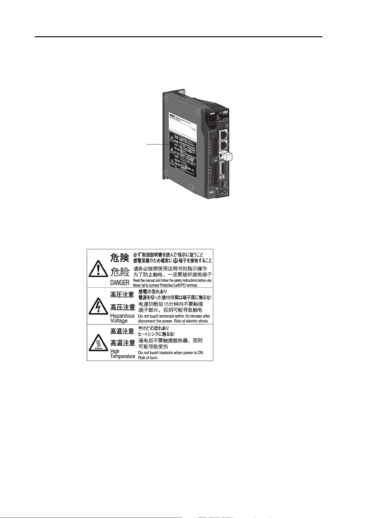
Location of Warning Label
The Servo Drive bears a warning label at the following location to provide handling warnings.
When handling the Servo Drive, be sure to observe the instructions provided on this label.
Warning label display location
VOLTAGE
PHASE
F L C
FREQ
POWER
SERIAL No.
OMRON Corporation
INPUT OUTPUT
100~120V
1Ø 3Ø
2.6A
50/60H
z
A09080004
0-120V
1.7A
0~500.0Hz
100W
MADE IN JAPAN
(R88D-KN02H-ECT-R)
Instructions on Warning Label
Disposal
• When disposing of the battery, insulate it using tape, and dispose of it by following the applicable
ordinances of your local government.
• Dispose of the Servo Drive as industrial waste.
10
OMNUC G5-series AC Servomotors and Servo Drives User’s Manual (with Built-in EtherCAT Communications)
Page 13
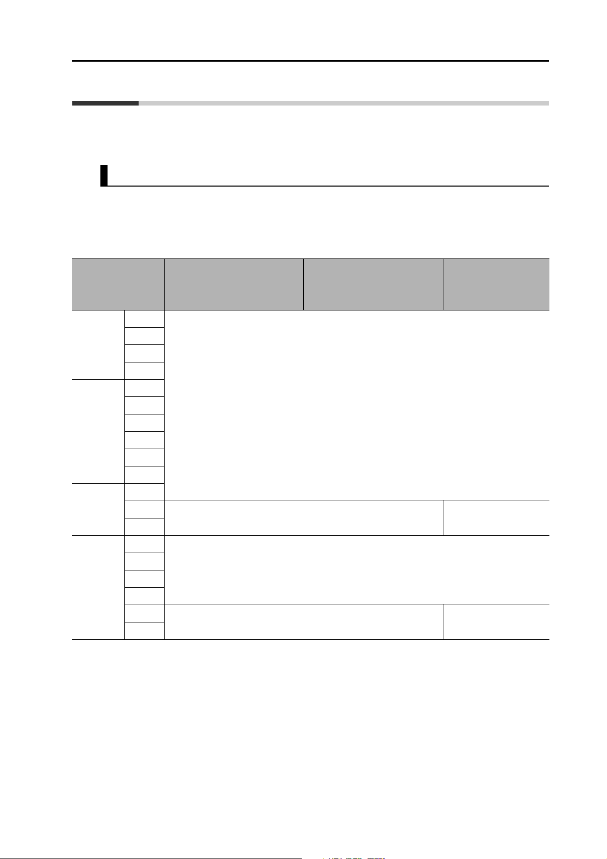
Items to Check after Unpacking
Items to Check after Unpacking
After unpacking, check the following items.
• Is this the model you ordered?
• Was there any damage sustained during shipment?
Accessories
Safety Precautions document x 1 copy
• Connectors, mounting screws, mounting brackets, and other accessories other than those in the
table below are not supplied. They must be prepared by the customer.
• If any item is missing or a problem is found such as Servo Drive damage, contact the OMRON
dealer or sales office where you purchased your product.
Specifications
Singlephase
100 VAC
Singlephase/3phase
200 VAC
3-phase
200 VAC
3-phase
400 VAC
50 W
100 W
200 W
400 W
100 W
200 W
400 W
750 W
1 kW
1.5 kW
2 kW
3 kW
5 kW
600 W
1 kW
1.5 kW
2 kW
3 kW
5 kW
Connector for main circuit
power supply terminals and
control circuit power supply
terminals
Connector for External
Regeneration Resistor
connection terminals and
Motor connection terminals
Included
− Included
Included
− Included
Safety bypass
connector
OMNUC G5-series AC Servomotors and Servo Drives User’s Manual (with Built-in EtherCAT Communications)
11
Page 14
Revision History
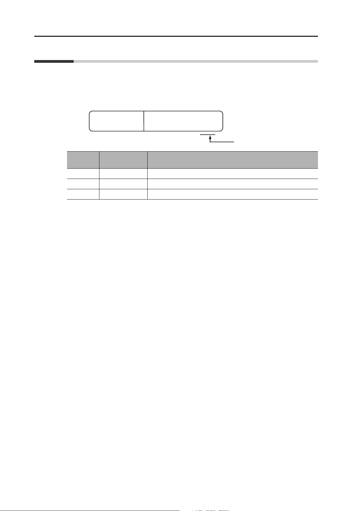
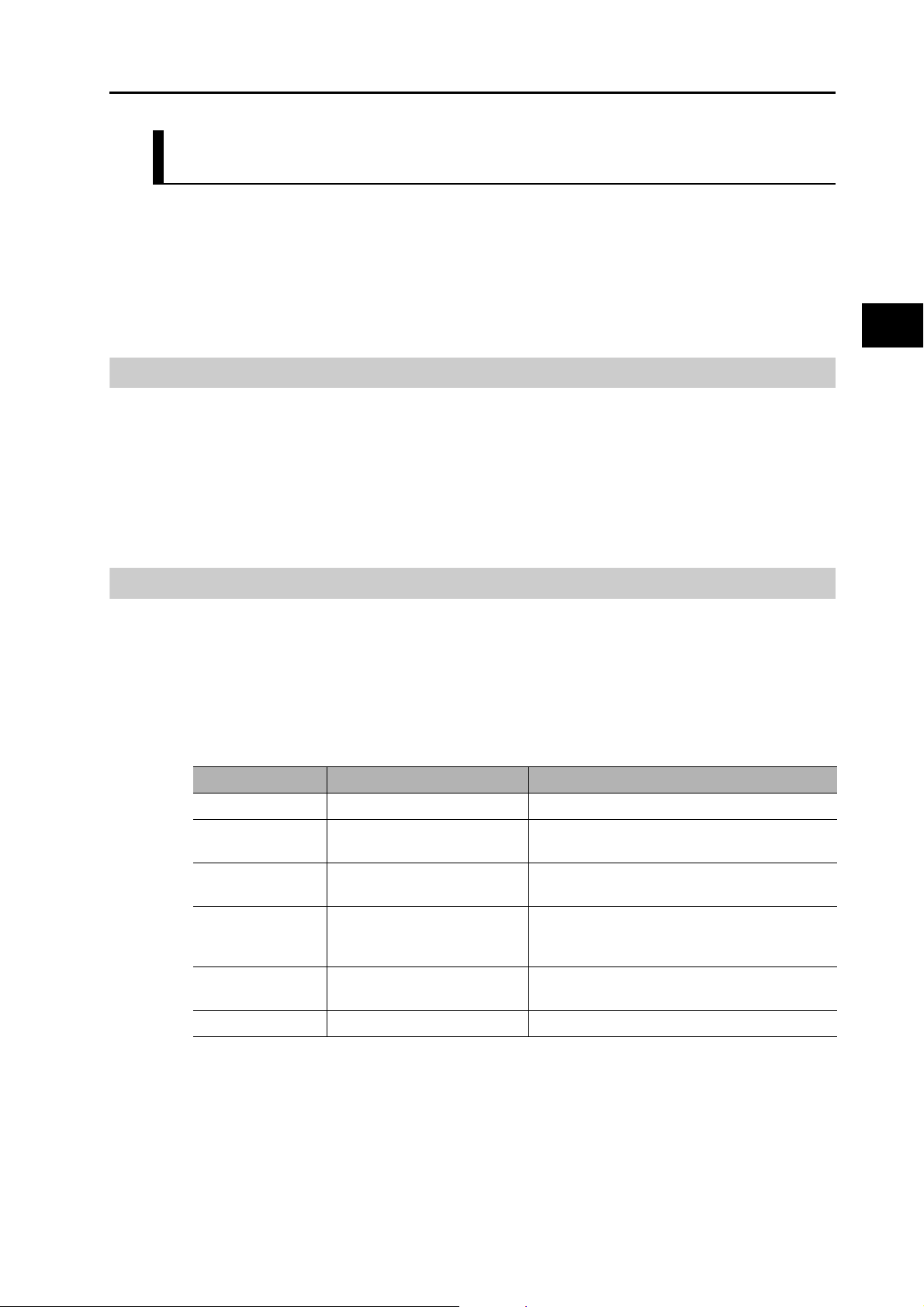
Revision History
The manual revision code is a number appended to the end of the catalog number found in the
bottom left-hand corner of the front or back cover.
Example
Cat. No.
Revision
code
01 March 2010 Original production
02 October 2010 Added models and made corrections.
03 July 2014 Added information and made corrections.
Revision Date Revised content
I573-E1-03
Revision code
12
OMNUC G5-series AC Servomotors and Servo Drives User’s Manual (with Built-in EtherCAT Communications)
Page 15
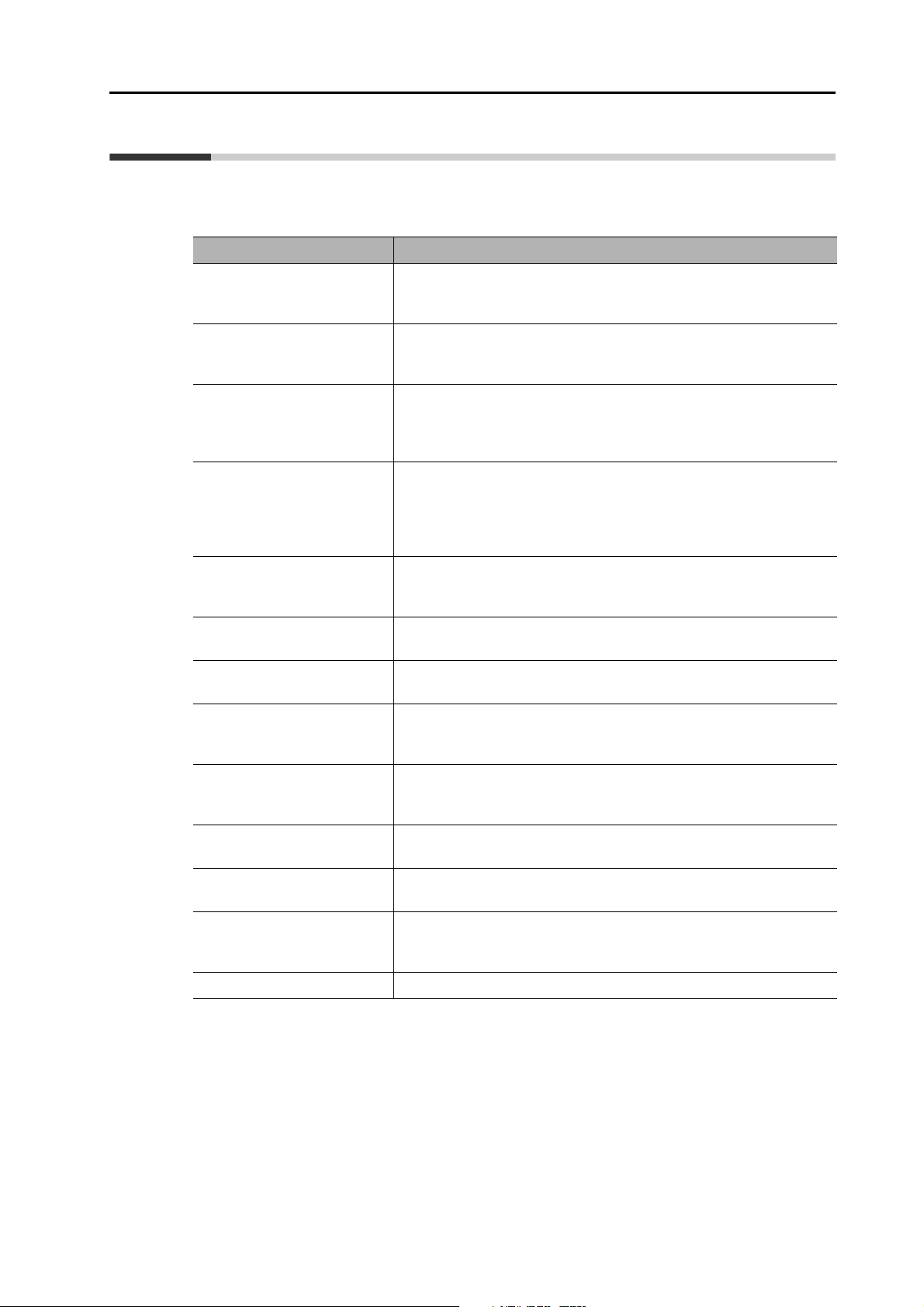
Structure of This Document
This manual consists of the following chapters.
Read the necessary chapter or chapters referring the following table.
Structure of This Document
Outline
Chapter 1 Features and
System
Configuration
Chapter 2 Standard Models
and External
Dimensions
Chapter 3 Specifications This chapter provides the general specifications, characteristics,
Chapter 4 System Design This chapter explains the installation conditions for the Servo Drive,
Chapter 5 EtherCAT
Communications
Chapter 6 CiA 402 Drive
Profile
Chapter 7 Applied
Functions
Chapter 8 Safety Function This chapter gives an outline of application functions, such as
Chapter 9 Details on Servo
Parameters and
Objects
Chapter 10 Operation This chapter gives the operating procedures and explains how to
Chapter 11 Adjustment
Functions
This chapter explains the features of the Servo Drive, name of each
part, and applicable EC Directives and UL standards.
This chapter explains the models of Servo Drives, Servomotors, and
peripheral equipment, and provides the external dimensions and
mounting dimensions.
connector specifications, and I/O circuits of the Servo Drives as well as
the general specifications, characteristics, encoder specifications of
the Servomotors and other peripheral devices.
Servomotor, and Decelerator, wiring methods including wiring
conforming to EMC Directives and regenerative energy calculation
methods as well as the performance of External Regeneration
Resistors.
This chapter describes EtherCAT communications under the
assumption that the Servo Drive is connected to a CJ1W-NC281/
NC481/NC881/NCF81/NC482/NC882 Position Control Unit.
This chapter describes the profile that is used to control the Servo
Drive.
This chapter outlines the applied functions such as the electronic gear,
gain switching and soft start, and explains the settings.
electronic gears, gain switching, and soft start, and explains the
settings.
This chapter explains the set values and contents of each object.
operate in each mode.
This chapter explains the functions, setting methods, and items to note
regarding various gain adjustments.
Chapter 12 Troubleshooting
and Maintenance
Appendix The appendix provides a list of objects and EtherCAT terminology.
OMNUC G5-series AC Servomotors and Servo Drives User’s Manual (with Built-in EtherCAT Communications)
This chapter explains the items to check when problems occur, error
diagnosis using the error display and measures, error diagnosis based
on the operating condition and measures, and periodic maintenance.
13
Page 16

Table Of Contents
Introduction ............................................................................................1
Terms and Conditions Agreement .........................................................2
Safety Precautions.................................................................................4
Items to Check after Unpacking...........................................................11
Revision History...................................................................................12
Structure of This Document .................................................................13
Chapter 1 Features and System Configuration
1-1 Outline ................................................................................................... 1-1
Outline of the OMNUC G5 Series................................................................................ 1-1
Features of OMNUC G5-series Servo Drives.............................................................. 1-1
What Is EtherCAT?...................................................................................................... 1-2
Object Dictionary ......................................................................................................... 1-2
1-2 System Configuration ............................................................................ 1-3
1-3 Names and Functions............................................................................ 1-4
Servo Drive Part Names.............................................................................................. 1-4
Servo Drive Functions ................................................................................................. 1-5
1-4 System Block Diagram .......................................................................... 1-6
1-5 Applicable Standards........................................................................... 1-11
EC Directives............................................................................................................. 1-11
UL and cUL Standards .............................................................................................. 1-12
Chapter 2 Models and External Dimensions
2-1 Servo System Configuration .................................................................. 2-1
2-2 How to Read Model Numbers................................................................ 2-3
Servo Drive.................................................................................................................. 2-3
Servomotors ................................................................................................................ 2-4
2-3 Model Tables ......................................................................................... 2-5
Servo Drive Model Table ............................................................................................. 2-5
Servomotor Model Tables ........................................................................................... 2-6
Servo Drive and Servomotor Combination Tables .................................................... 2-10
Cable and Peripheral Device Model Tables .............................................................. 2-12
2-4 External and Mounting Dimensions ..................................................... 2-21
Servo Drive Dimensions ............................................................................................ 2-21
Servomotor Dimensions ............................................................................................ 2-31
External Regeneration Resistor Dimensions ............................................................. 2-50
2-5 EMC Filter Dimensions ........................................................................ 2-51
14
OMNUC G5-series AC Servomotors and Servo Drives User’s Manual (with Built-in EtherCAT Communications)
Page 17

Table Of Contents
Chapter 3 Specifications
3-1 Servo Drive Specifications......................................................................3-1
General Specifications................................................................................................. 3-1
Characteristics............................................................................................................. 3-2
EtherCAT Communications Specifications.................................................................. 3-6
Main Circuit and Motor Connections ........................................................................... 3-7
EtherCAT Communications Connector Specifications (RJ45) .................................. 3-12
Control I/O Connector Specifications (CN1).............................................................. 3-13
Control Input Circuits ................................................................................................. 3-16
Control Input Details .................................................................................................. 3-17
Control Output Circuits .............................................................................................. 3-19
Control Output Details ............................................................................................... 3-20
Encoder Connector Specifications (CN2).................................................................. 3-23
External Encoder Connector Specifications (CN4).................................................... 3-23
Analog Monitor Connector Specifications (CN5) ....................................................... 3-27
USB Connector Specifications (CN7)........................................................................ 3-28
Safety Connector Specifications (CN8) ..................................................................... 3-29
3-2 Overload Characteristics (Electronic Thermal Function) ......................3-31
Overload Characteristics Graphs .............................................................................. 3-31
3-3 Servomotor Specifications....................................................................3-32
General Specifications............................................................................................... 3-32
Characteristics........................................................................................................... 3-33
Encoder Specifications .............................................................................................. 3-56
3-4 Cable and Connector Specifications ....................................................3-57
Encoder Cable Specifications.................................................................................... 3-57
Absolute Encoder Battery Cable Specifications ........................................................ 3-59
Motor Power Cable Specifications............................................................................. 3-60
Connector Specifications........................................................................................... 3-67
EtherCAT Communications Cable Specifications ..................................................... 3-70
Analog Monitor Cable Specifications......................................................................... 3-73
Control Cable Specifications ..................................................................................... 3-75
3-5 External Regeneration Resistor Specifications ....................................3-80
External Regeneration Resistor Specifications ......................................................... 3-80
3-6 EMC Filter Specifications .....................................................................3-82
Chapter 4 System Design
4-1 Installation Conditions ............................................................................4-1
Servo Drive Installation Conditions.............................................................................. 4-1
Servomotor Installation Conditions.............................................................................. 4-2
Decelerator Installation Conditions.............................................................................. 4-5
4-2 Wiring .....................................................................................................4-6
Peripheral Equipment Connection Examples.............................................................. 4-6
Main Circuit and Motor Connections ......................................................................... 4-12
4-3 Wiring Conforming to EMC Directives ..................................................4-20
Wiring Method ........................................................................................................... 4-20
Selecting Connection Component ............................................................................. 4-27
4-4 Regenerative Energy Absorption..........................................................4-41
Calculating the Regenerative Energy ........................................................................ 4-41
Servo Drive Regeneration Absorption Capacity ........................................................ 4-43
Regenerative Energy Absorption with an External Regeneration Resistor ............... 4-44
Connecting an External Regeneration Resistor ........................................................ 4-45
OMNUC G5-series AC Servomotors and Servo Drives User’s Manual (with Built-in EtherCAT Communications)
15
Page 18

Table Of Contents
Chapter 5 EtherCAT Communications
5-1 Display Area and Settings ..................................................................... 5-1
Node Address Setting.................................................................................................. 5-1
Status Indicators.......................................................................................................... 5-2
5-2 Structure of the CAN Application Protocol over EtherCAT .................... 5-3
5-3 EtherCAT State Machine ....................................................................... 5-4
5-4 Process Data Objects (PDOs) ............................................................... 5-5
PDO Mapping Settings ................................................................................................ 5-5
Sync Manager PDO Assignment Settings ................................................................... 5-6
Fixed PDO Mapping .................................................................................................... 5-6
5-5 Service Data Objects (SDOs) ................................................................ 5-7
Abort Codes................................................................................................................. 5-7
5-6 Synchronization with Distributed Clocks................................................ 5-8
Communications Cycle (DC Cycle) ............................................................................. 5-8
5-7 Emergency Messages ........................................................................... 5-9
Chapter 6 Drive Profile
6-1 Controlling the State Machine of the Servo Drive.................................. 6-1
State Machine.............................................................................................................. 6-1
6-2 Modes of Operation ............................................................................... 6-4
6-3 Cyclic Synchronous Position Mode ....................................................... 6-5
Related Objects ........................................................................................................... 6-6
Block Diagram for Position Control Mode.................................................................... 6-7
6-4 Torque Limit........................................................................................... 6-8
Related Objects ........................................................................................................... 6-8
6-5 Touch Probe Function (Latch Function) ................................................ 6-9
Related Objects ........................................................................................................... 6-9
Trigger Signal Settings ................................................................................................ 6-9
Operation Sequences................................................................................................ 6-10
6-6 Fully-closed Control ............................................................................. 6-12
Outline of Operation .................................................................................................. 6-12
Objects Requiring Settings ........................................................................................ 6-13
Parameter Block Diagram for Fully-closed Control Mode ......................................... 6-18
6-7 Object Dictionary ................................................................................. 6-19
Object Dictionary Area............................................................................................... 6-19
Data Types ................................................................................................................ 6-19
Object Description Format ......................................................................................... 6-20
Communication Objects ............................................................................................ 6-21
PDO Mapping Objects............................................................................................... 6-27
Sync Manager Communication Objects .................................................................... 6-29
Manufacturer Specific Objects................................................................................... 6-33
Servo Drive Profile Object ......................................................................................... 6-36
Reserved Objects ...................................................................................................... 6-52
6-8 Connecting with OMRON Controllers .................................................. 6-53
Related Objects ......................................................................................................... 6-53
16
OMNUC G5-series AC Servomotors and Servo Drives User’s Manual (with Built-in EtherCAT Communications)
Page 19

Table Of Contents
Chapter 7 Applied Functions
7-1 Sequence I/O Signals.............................................................................7-1
Input Signals................................................................................................................ 7-1
Output Signals ............................................................................................................. 7-4
7-2 Forward and Reverse Drive Prohibition Functions .................................7-6
Objects Requiring Settings .......................................................................................... 7-6
7-3 Overrun Protection .................................................................................7-9
Operating Conditions................................................................................................... 7-9
Objects Requiring Settings .......................................................................................... 7-9
Operation Example.................................................................................................... 7-10
7-4 Backlash Compensation.......................................................................7-11
Objects Requiring Settings ........................................................................................ 7-11
7-5 Brake Interlock......................................................................................7-13
Objects Requiring Settings ........................................................................................ 7-13
Operation Timing ....................................................................................................... 7-14
7-6 Electronic Gear Function ......................................................................7-18
Objects Requiring Settings ........................................................................................ 7-18
Operation Example.................................................................................................... 7-20
7-7 Torque Limit Switching .........................................................................7-21
Operating Conditions................................................................................................. 7-21
Objects Requiring Settings ........................................................................................ 7-21
7-8 Gain Switching Function.......................................................................7-23
Objects Requiring Settings ........................................................................................ 7-24
Gain Switching........................................................................................................... 7-25
Diagrams of Gain Switching Setting .......................................................................... 7-27
7-9 Gain Switching 3 Function....................................................................7-30
Operating Conditions................................................................................................. 7-30
Objects Requiring Settings ........................................................................................ 7-30
Operation Example.................................................................................................... 7-31
Chapter 8 Safety Function
8-1 Safe Torque OFF Function.....................................................................8-1
I/O Signal Specifications.............................................................................................. 8-2
8-2 Operation Example.................................................................................8-4
8-3 Connection Examples.............................................................................8-6
Chapter 9 Details on Servo Parameter Objects
9-1 Basic Settings.........................................................................................9-1
9-2 Gain Settings..........................................................................................9-6
9-3 Vibration Suppression Settings ............................................................9-15
9-4 Analog Control Objects.........................................................................9-21
9-5 Interface Monitor Settings.....................................................................9-24
9-6 Extended Objects .................................................................................9-32
OMNUC G5-series AC Servomotors and Servo Drives User’s Manual (with Built-in EtherCAT Communications)
17
Page 20

Table Of Contents
9-7 Special Objects.................................................................................... 9-38
9-8 Reserved Objects ................................................................................ 9-50
Chapter 10Operation
10-1 Operational Procedure......................................................................... 10-1
10-2 Preparing for Operation ....................................................................... 10-2
Items to Check Before Turning ON the Power Supply .............................................. 10-2
Turning ON the Power Supply................................................................................... 10-3
Checking the Displays ............................................................................................... 10-4
Absolute Encoder Setup............................................................................................ 10-6
Setting Up an Absolute Encoder from the CX-Drive.................................................. 10-6
10-3 Trial Operation ..................................................................................... 10-7
Preparations for Trial Operation ................................................................................ 10-7
Test Operation via USB Communications from the CX-Drive ................................... 10-8
Chapter 11Adjustment Functions
11-1 Analog Monitor..................................................................................... 11-1
Objects Requiring Settings ........................................................................................ 11-1
11-2 Gain Adjustment .................................................................................. 11-4
Purpose of the Gain Adjustment................................................................................ 11-4
Gain Adjustment Methods ......................................................................................... 11-4
Gain Adjustment Procedure ...................................................................................... 11-5
11-3 Realtime Autotuning ............................................................................ 11-6
Objects Requiring Settings ........................................................................................ 11-7
Setting Realtime Autotuning ...................................................................................... 11-7
Setting Machine Rigidity ............................................................................................ 11-8
11-4 Manual Tuning ................................................................................... 11-13
Basic Settings.......................................................................................................... 11-13
11-5 Damping Control................................................................................ 11-15
Outline of Operation ................................................................................................ 11-15
Objects Requiring Settings ...................................................................................... 11-15
11-6 Adaptive Filter.................................................................................... 11-18
Objects Requiring Settings ...................................................................................... 11-19
Operating Procedure ............................................................................................... 11-20
11-7 Notch Filters....................................................................................... 11-21
Objects Requiring Settings ...................................................................................... 11-22
11-8 Disturbance Observer Function ......................................................... 11-24
Operating Conditions............................................................................................... 11-24
Objects Requiring Settings ...................................................................................... 11-25
Operating Procedure ............................................................................................... 11-25
11-9 Friction Torque Compensation Function............................................ 11-26
Operating Conditions............................................................................................... 11-26
Objects Requiring Settings ...................................................................................... 11-26
Operation Example.................................................................................................. 11-27
18
OMNUC G5-series AC Servomotors and Servo Drives User’s Manual (with Built-in EtherCAT Communications)
Page 21

Table Of Contents
11-10 Hybrid Vibration Suppression Function .............................................11-28
Operating Conditions............................................................................................... 11-28
Objects Requiring Settings ...................................................................................... 11-28
Operating Procedure ............................................................................................... 11-28
11-11 Feed-forward Function ......................................................................11-29
Objects Requiring Settings ...................................................................................... 11-29
Operating Procedure ............................................................................................... 11-30
11-12 Instantaneous Speed Observer Function ..........................................11-32
Operating Conditions............................................................................................... 11-32
Objects Requiring Settings ...................................................................................... 11-32
Operating Procedure ............................................................................................... 11-33
Chapter 12Troubleshooting and Maintenance
12-1 Troubleshooting....................................................................................12-1
Preliminary Checks When a Problem Occurs ........................................................... 12-1
Precautions When a Problem Occurs ....................................................................... 12-2
Replacing the Servomotor or Servo Drive ................................................................. 12-2
12-2 Warnings ..............................................................................................12-4
Related Objects ......................................................................................................... 12-4
Warning List............................................................................................................... 12-5
12-3 Errors....................................................................................................12-7
Immediate Stop Operation at Errors........................................................................ 12-11
12-4 Troubleshooting..................................................................................12-13
Troubleshooting with Error Displays........................................................................ 12-13
Troubleshooting Using the Operation State ............................................................ 12-25
12-5 Periodic Maintenance .........................................................................12-31
Servomotor Life Expectancy.................................................................................... 12-31
Servo Drive Life Expectancy ................................................................................... 12-32
Replacing the Absolute Encoder Battery ................................................................ 12-33
Appendices
A-1 Object List.............................................................................................. A-1
A-2 EtherCAT Terminology ........................................................................ A-19
Index
OMNUC G5-series AC Servomotors and Servo Drives User’s Manual (with Built-in EtherCAT Communications)
19
Page 22

Page 23

Features and System Configuration
This chapter explains the features of the Servo Drive, name of each part, and
applicable EC Directives and UL standards.
1-1 Outline ...........................................................................1-1
1-2 System Configuration ..................................................1-3
1-3 Names and Functions ..................................................1-4
1-4 System Block Diagram.................................................1-6
1-5 Applicable Standards .................................................1-11
1
OMNUC G5-series AC Servomotors and Servo Drives User’s Manual (with Built-in EtherCAT Communications)
Page 24

1
1-1 Outline
1-1 Outline
Outline of the OMNUC G5 Series
The OMNUC G5-series Servo Drives with Built-in EtherCAT Communications support 100Mbps EtherCAT.
When you use the Servo Drive with a Position Control Unit with EtherCAT interface (CJ1WNC@8@), you can create a sophisticated positioning control system. Also, you need only one
communications cable to connect the Servo Drive and the Controller. Therefore, you can
realize a position control system easily with reduced wiring effort.
With real time autotuning, adaptive filter, notch filter, and damping control, you can set up a
system that provides stable operation by suppressing vibration in low-rigidity machines.
Features of OMNUC G5-series Servo Drives
OMNUC G5-series Servo Drives have the following features.
Data Transmission Using EtherCAT Communications
When you use it with a Position Control Unit with EtherCAT interface (CJ1W-NC@8@), you can
exchange all control data between the Servo Drive and the Controller through high-speed data
communications.
Since the various control commands are transmitted via data communications, Servomotor's
operational performance is maximized without being limited by interface specifications such as
the response frequency of the encoder feedback pulses.
You can use the Servo Drive's various control parameters and monitor data on a host
controller, and unify the system data for management.
Features and System Configuration
Achievement of Accurate Positioning by Fully-closed Control
Feedback from the external encoder connected to the motor is used to accurately control
positioning. Position control is not affected by deviations caused by ball screws or temperature
changes.
Wide Range of Power Supplies to Meet Any Need
The OMNUC G5 Series now has models supporting 400 V for use with large equipment, at
overseas facilities and in wide-ranging applications and environment. Since the utilization ratio
of facility equipment also increases, the TCO (total cost of ownership) will come down.
1-1
Safe Torque OFF (STO) Function to Ensure Safety
You can cut off the motor current to stop the motor based on a signal from an emergency stop
button or other safety equipment. This can be used for an emergency stop circuit that is
compliant with safety standards without using an external contactor. Even during the torque
OFF status, the present position of the motor is monitored by the control circuits to eliminate
the need to perform an origin search when restarting.
OMNUC G5-series AC Servomotors and Servo Drives User’s Manual (with Built-in EtherCAT Communications)
Page 25
1-1 Outline
Suppressing Vibration of Low-rigidity Mechanisms during Acceleration/
Deceleration
The damping control function suppresses vibration of low-rigidity mechanisms or devices
whose tips tend to vibrate.
Two damping filters are provided to enable switching the damping frequency automatically
according to the rotation direction and also via an external signal. In addition, the settings can
be made easily by setting the damping frequency and filter values. You are assured of stable
operation even if the set values are inappropriate.
1
What Is EtherCAT?
EtherCAT is an open high-speed industrial network system that conforms to Ethernet (IEEE
802.3). Each node achieves a short cycle time by transmitting Ethernet frames at high speed.
A mechanism that allows sharing clock information enables high-precision synchronization
control with low communications jitter.
EtherCAT is a registered trademark of Beckhoff Automation Gmbh (Germany). EtherCAT
technology is protected by patents.
Object Dictionary
OMNUC G5-series Servo Drives with Built-in EtherCAT Communications use the object
dictionary for CAN application protocol over EtherCAT (CoE) as a base for communications.
An object is a special data structure inside a device that consists of data, parameters, and
methods.
An object dictionary is a data structure that describes the data type objects, communications
objects, and application objects.
All objects are assigned four-digit hexadecimal numbers in the areas shown in the following
table.
Indexes Area Contents
0000 to 0FFF hex Data Type Area Definitions of data types.
1000 to 1FFF hex CoE Communications Area Definitions of variables that can be used by all
2000 to 2FFF hex Manufacturer Specific Area 1 Variables with common definitions for all
Features and System Configuration
servers for designated communications.
OMRON products.
3000 to 5FFF hex Manufacturer Specific Area 2 Variables with common definitions for all
OMNUC G5-series Servo Drives (servo
parameters).
6000 to 9FFF hex Device Profile Area Variables defined in the Servo Drive's CiA402
drive profile.
A000 to FFFF hex Reserved Area Area reserved for future use.
OMNUC G5-series AC Servomotors and Servo Drives User’s Manual (with Built-in EtherCAT Communications)
1-2
Page 26
1-2 System Configuration
BS
(EtherCAT
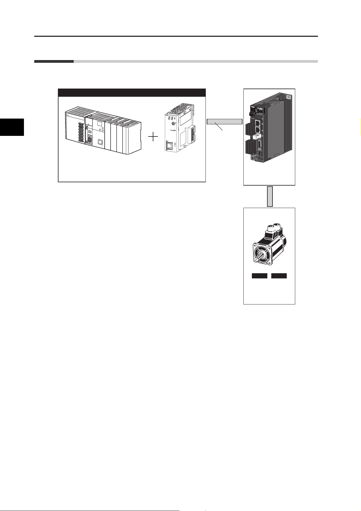
1-2 System Configuration
The system configuration for a OMNUC G5-Series AC Servo Drive with Built-in EtherCAT
Communications is shown below.
1
Controller (EtherCAT
Programmable Controller
SYSMAC CJ2
)
Position Control Unit
CJ1W-NC@8@
EtherCAT
OMNUC G5 Series
AC Servo Drive
R88D-KN@-ECT-R
Features and System Configuration
INCNCABS
OMNUC G5 Series
AC Servomotor
R88M-K@
1-3
OMNUC G5-series AC Servomotors and Servo Drives User’s Manual (with Built-in EtherCAT Communications)
Page 27
1-3 Names and Functions
A
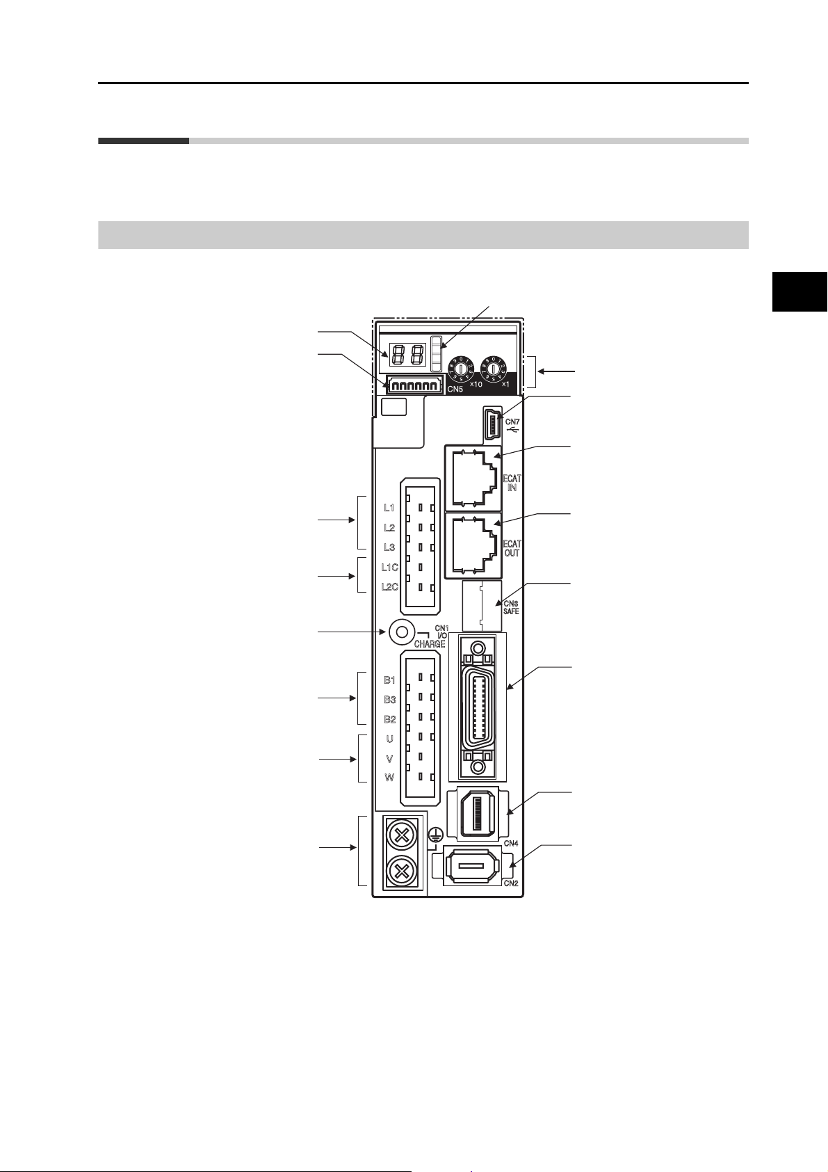
This section describes the names and functions of Servo Drive parts.
Servo Drive Part Names
The Servo Drive part names are given below.
1-3 Names and Functions
EtherCAT status indicators
Seven-segment display
nalog monitor connector (CN5)
power supply terminals
power supply terminals
External Regeneration
Resistor connection
terminals (B1, B2, and B3)
Main circuit
(L1, L2, and L3)
Control circuit
(L1C and L2C)
Charge lamp
ADR
Rotary switches for node
address setting
USB connector (CN7)
EtherCAT communications
connector: ECAT IN
EtherCAT communications
connector: ECAT OUT
Safety connector (CN8)
Control I/O connector (CN1)
1
Features and System Configuration
Motor connection
terminals (U, V, and W)
External encoder
connector (CN4)
Protective ground terminals
OMNUC G5-series AC Servomotors and Servo Drives User’s Manual (with Built-in EtherCAT Communications)
Encoder connector (CN2)
1-4
Page 28

1
1-3 Names and Functions
Servo Drive Functions
The functions of each part are described below.
Display
A 2-digit 7-segment display shows the node address, error codes, and other Servo Drive
status.
Charge Lamp
Lights when the main circuit power supply is turned ON.
EtherCAT Status Indicators
These indicators show the status of EtherCAT communications.
For details, refer to Status Indicators on page 5-2.
Control I/O Connector (CN1)
Used for command input signals and I/O signals.
Encoder Connector (CN2)
Connector for the encoder installed in the Servomotor.
External Encoder Connector (CN4)
Features and System Configuration
Connector for an encoder signal used during fully-closed control.
EtherCAT Communications Connectors (ECAT IN and ECAT OUT)
These connectors are for EtherCAT communications.
Analog Monitor Connector (CN5)
You can use a special cable to monitor values, such as the motor rotation speed, torque
command value, etc.
1-5
USB Connector (CN7)
Communications connector for the computer.
Safety Connector (CN8)
Connector for safety devices.
If no safety devices are used, keep the factory-set safety bypass connector installed.
OMNUC G5-series AC Servomotors and Servo Drives User’s Manual (with Built-in EtherCAT Communications)
Page 29
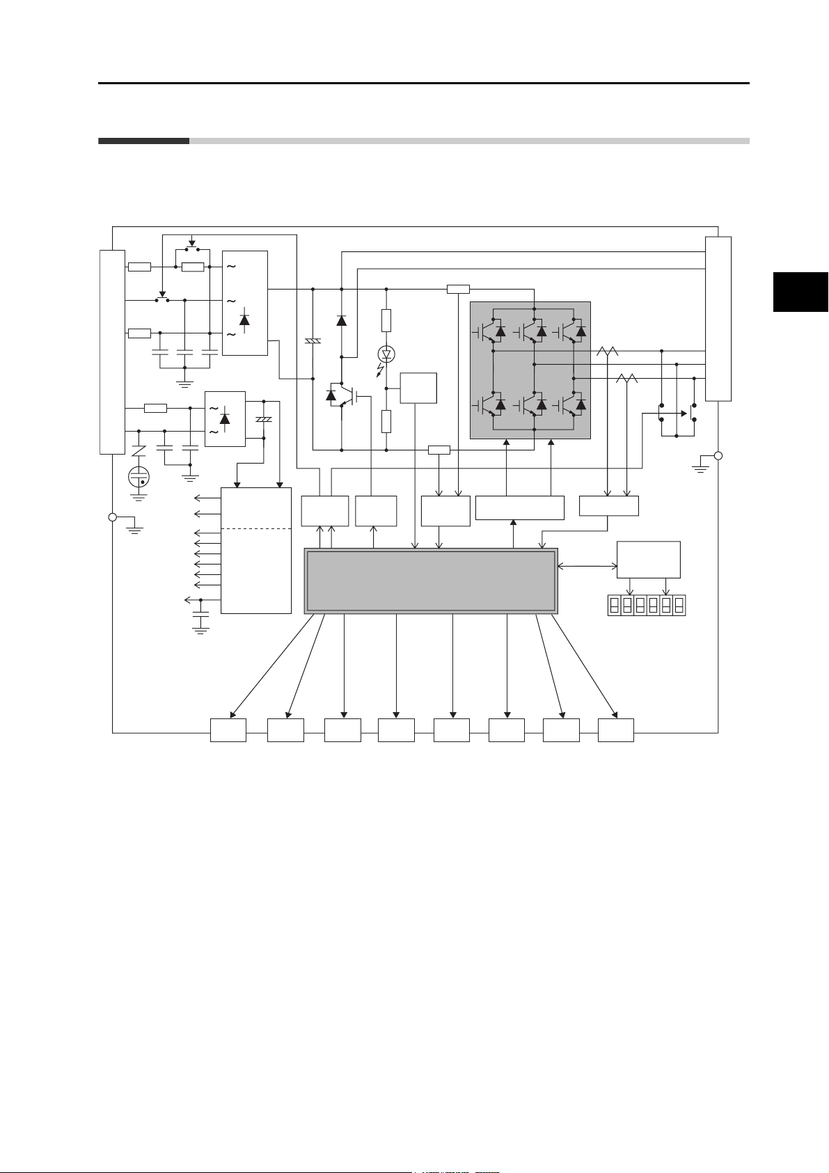
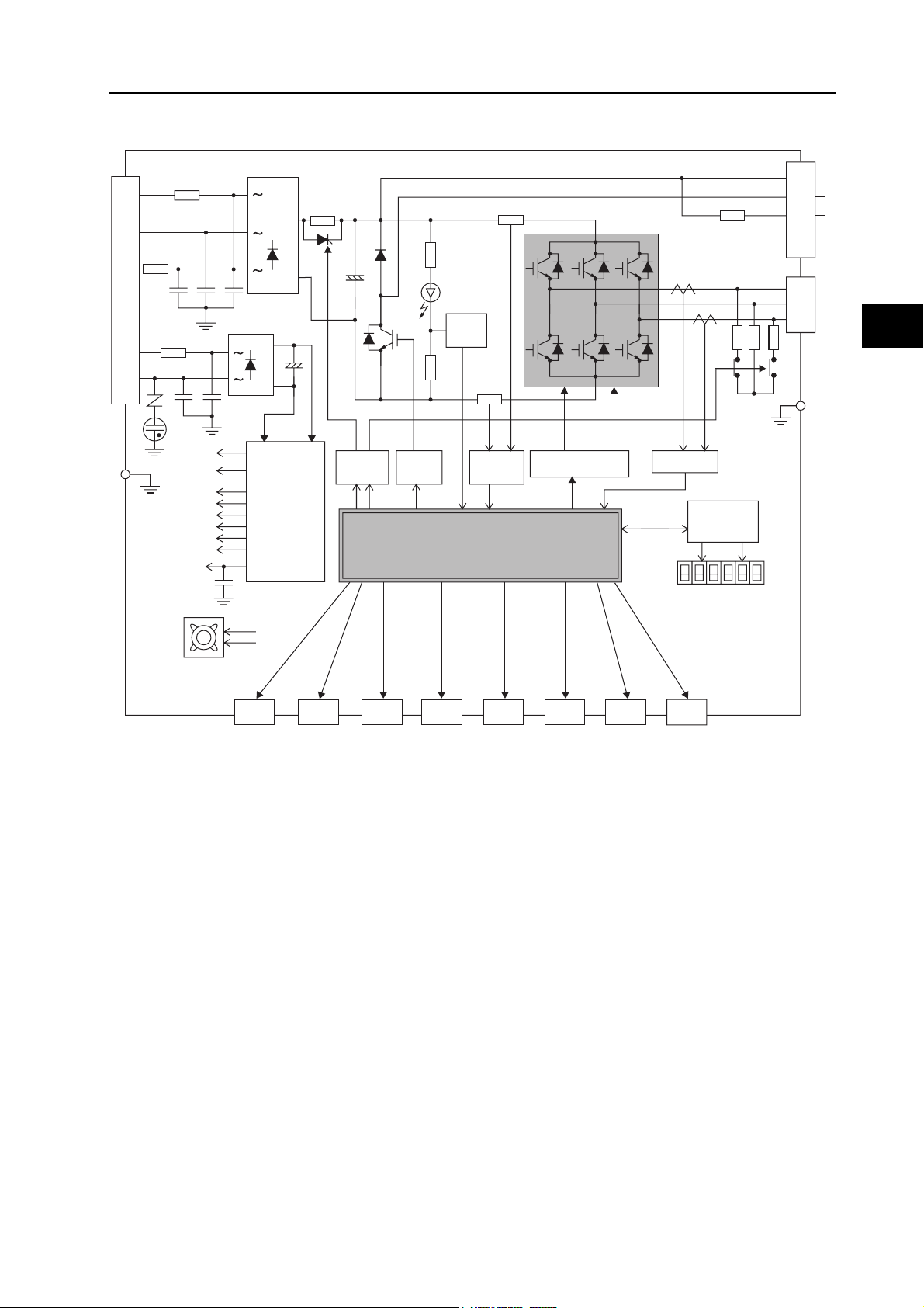
1-4 System Block Diagram
This is the block diagram of the OMNUC G5-series AC Servo Drive with Built-in EtherCAT
Communications.
R88D-KNA5L-ECT-R/-KN01L-ECT-R/-KN02L-ECT-R
R88D-KN01H-ECT-R/-KN02H-ECT-R/-KN04H-ECT-R
1-4 System Block Diagram
L1
L2
L3
L1C
L2C
CN A
FUSE
FUSE
FG
FUSE
15 V
G1
5 V
3.3 V
2.5 V
1.5 V
E5V
±12 V
G2
+
−
+
−
SW power
supply main
circuit control
Internal
control power
supply
Volta ge
detection
Relay
drive
Regeneration
control
MPU & ASIC
Position, speed, and torque calculation control area
• PWM control
Overcurrent
detection
Gate drive
Current detection
Display and
setting circuit
area
CN B
B1
B2
B3
W
1
U
V
FG
Features and System Configuration
ECAT
IN
EtherCAT
communications
connector
OMNUC G5-series AC Servomotors and Servo Drives User’s Manual (with Built-in EtherCAT Communications)
ECAT
OUT
EtherCAT
communications
connector
Control
interface
CN2 CN4 CN5 CN7
Encoder
External
encoder
Analog
monitor
CN8CN1
USB Safety
1-6
Page 30
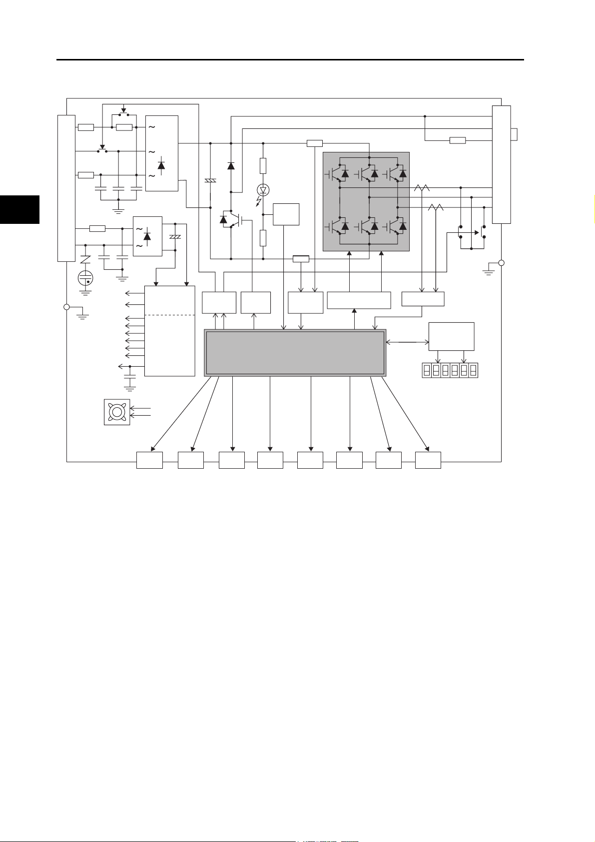
1-4 System Block Diagram
R88D-KN04L-ECT-R
R88D-KN08H-ECT-R/-KN10H-ECT-R/-KN15H-ECT-R
1
L1
L2
L3
L1C
L2C
CN A
FUSE
FUSE
FG
FUSE
15 V
G1
5 V
3.3 V
2.5 V
1.5 V
E5V
±12 V
G2
+
−
+
−
SW power
supply main
circuit control
Internal
control power
supply
Volta ge
detection
Relay
drive
MPU & ASIC
Position, speed, and torque calculation control area
• PWM control
Regeneration
control
Overcurrent
detection
Gate drive
Internal regeneration
resistor
Current detection
Display and
setting circuit
area
CN B
B1
B2
B3
U
V
W
FG
Axial fan
ECAT
IN
Features and System Configuration
EtherCAT
communications
connector
ECAT
OUT
EtherCAT
communications
connector
Control
interface
Encoder
CN4 CN5 CN7
External
encoder
Analog
monitor
CN8CN2CN1
USB Safety
1-7
OMNUC G5-series AC Servomotors and Servo Drives User’s Manual (with Built-in EtherCAT Communications)
Page 31
R88D-KN20H-ECT-R/-KN30H-ECT-R/-KN50H-ECT-R
1-4 System Block Diagram
L1
L2
L3
L1C
L2C
CN A
FUSE
FG
FUSE
FUSE
15 V
G1
5 V
3.3 V
2.5 V
1.5 V
E5V
±12 V
G2
+
−
+
−
SW power
supply main
circuit control
Internal
control power
supply
Voltage
detection
Relay
drive
MPU & ASIC
Position, speed, and torque calculation control area
• PWM control
Regeneration
control
Overcurrent
detection
Gate drive
Internal regeneration
resistor
Current detection
Display and
setting circuit
area
CN C
CN B
B1
B2
B3
NC
U
V
W
1
Features and System Configuration
FG
Axial fan
communications
ECAT
IN
EtherCAT
connector
ECAT
OUT
EtherCAT
communications
connector
Control
interface
Encoder
CN4 CN5 CN7
External
encoder
Analog
monitor
CN8CN2CN1
USB Safety
OMNUC G5-series AC Servomotors and Servo Drives User’s Manual (with Built-in EtherCAT Communications)
1-8
Page 32

1-4 System Block Diagram
R88D-KN06F-ECT-R/-KN10F-ECT-R/-KN15F-ECT-R/-KN20F-ECT-R
1
L1
L2
L3
24 V
0 V
CN A
FUSE
FUSE
CN C
FUSE
FG
15 V
G1
5 V
3.3 V
2.5 V
1.5 V
E5V
±12 V
G2
+
+
DC-DC
−
−
SW power
supply main
circuit control
Internal
control power
supply
CN D
B1
B2
CN B
B3
NC
U
V
W
FG
+
−
Volta ge
detection
Relay
drive
MPU & ASIC
Position, speed, and torque calculation control area
• PWM control
Regeneration
control
Overcurrent
detection
Gate drive
Internal regeneration
resistor
Current detection
Display and
setting circuit
area
Axial fan
ECAT
IN
EtherCAT
communications
Features and System Configuration
connector
ECAT
OUT
EtherCAT
communications
connector
Control
interface
CN2CN1
Encoder
CN4 CN5 CN7
External
encoder
Analog
monitor
CN8
USB Safety
1-9
OMNUC G5-series AC Servomotors and Servo Drives User’s Manual (with Built-in EtherCAT Communications)
Page 33

R88D-KN30F-ECT-R/-KN50F-ECT-R
1-4 System Block Diagram
L1
L2
L3
24 V
0 V
CN A
FUSE
CN C
FUSE
FG
FUSE
15 V
G1
5 V
3.3 V
2.5 V
1.5 V
E5V
±12 V
G2
+
+
DC-DC
−
−
SW power
supply main
circuit control
Internal
control power
supply
CN D
B1
B2
CN B
B3
NC
U
V
W
FG
1
Features and System Configuration
+
−
Volta ge
detection
Relay
drive
MPU & ASIC
Position, speed, and torque calculation control area
• PWM control
Regeneration
control
Overcurrent
detection
Gate drive
Internal regeneration
resistor
Current detection
Display and
setting circuit
area
Axial fan
EtherCAT
communications
connector
ECAT
IN
ECAT
OUT
EtherCAT
communications
connector
Control
interface
CN2CN1
Encoder
CN4 CN5 CN7
External
encoder
Analog
monitor
CN8
USB Safety
OMNUC G5-series AC Servomotors and Servo Drives User’s Manual (with Built-in EtherCAT Communications)
1-10
Page 34

1-5 Applicable Standards
1-5 Applicable Standards
This section describes applicable EMC Directives.
EC Directives
1
EC
Directive
Low
Voltage
Directive
EMC
Directive
Machinery
Directive
Note: To conform to EMC Directives, the Servomotor and Servo Drive must be installed under the conditions described
in 4-3 Wiring Conforming to EMC Directives on page 4-20.
Product Applicable standards
AC Servo Drives EN 61800-5-1
AC Servomotors EN 60034-1/-5
AC Servo Drives EN 55011 class A group 1
AC Servo Drives EN 954-1 (Category 3)
Features and System Configuration
IEC 61800-3
EN 61000-6-2
EN ISO 13849-1: 2008 (PLc, d)
ISO 13849-1: 2006 (PLc, d)
EN 61508 (SIL 2)
EN 62061 (SIL 2)
EN 61800-5-2 (STO)
IEC 61326-3-1 (SIL 2)
1-11
OMNUC G5-series AC Servomotors and Servo Drives User’s Manual (with Built-in EtherCAT Communications)
Page 35

UL and cUL Standards
Standard Product Applicable standards File number
UL
standards
CSA
standards
AC Servo Drives UL 508C E179149
AC Servomotors UL 1004-1 E331224
AC Servo Drives CSA 22.2 No. 14 E179149
AC Servomotors CSA 22.2 No. 100 E331224
1-5 Applicable Standards
The Servo Drives and Servomotors comply with UL 508C (file No. E179149) as long as the
following installation conditions 1 and 2 are met.
(1) Use the Servo Drive in a pollution degree 1 or 2 environment as defined in IEC 60664-1
(example: installation in an IP54 control panel).
(2) Be sure to connect a circuit breaker or fuse, which is a UL-listed product with LISTED and
mark, between the power supply and noise filter.
Refer to the following table for the rated current of the circuit breaker or fuse.
Use copper wiring with a temperature rating of 75°C or higher.
Servo Drive model number Rated current of circuit breaker (A)
R88D-KNA5L-ECT-R 10
R88D-KN01L-ECT-R 10
R88D-KN02L-ECT-R 10
R88D-KN04L-ECT-R 10
R88D-KN01H-ECT-R 10
R88D-KN02H-ECT-R 10
R88D-KN04H-ECT-R 10
R88D-KN08H-ECT-R 15
R88D-KN10H-ECT-R 15
R88D-KN15H-ECT-R 20
R88D-KN20H-ECT-R 30
1
Features and System Configuration
R88D-KN30H-ECT-R 50
R88D-KN50H-ECT-R 50
R88D-KN06F-ECT-R 15
R88D-KN10F-ECT-R 15
R88D-KN15F-ECT-R 15
R88D-KN20F-ECT-R 20
R88D-KN30F-ECT-R 30
R88D-KN50F-ECT-R 30
OMNUC G5-series AC Servomotors and Servo Drives User’s Manual (with Built-in EtherCAT Communications)
1-12
Page 36

Page 37

Models and External
Dimensions
This chapter explains the models of Servo Drive, Servomotor, and peripheral
devices, and provides the external dimensions and mounting dimensions.
2-1 Servo System Configuration .......................................2-1
2-2 How to Read Model Numbers ......................................2-3
2-3 Model Tables .................................................................2-5
2-4 External and Mounting Dimensions..........................2-21
2-5 EMC Filter Dimensions...............................................2-51
2
OMNUC G5-series AC Servomotors and Servo Drives User’s Manual (with Built-in EtherCAT Communications)
Page 38
2-1 Servo System Configuration
2-1 Servo System Configuration
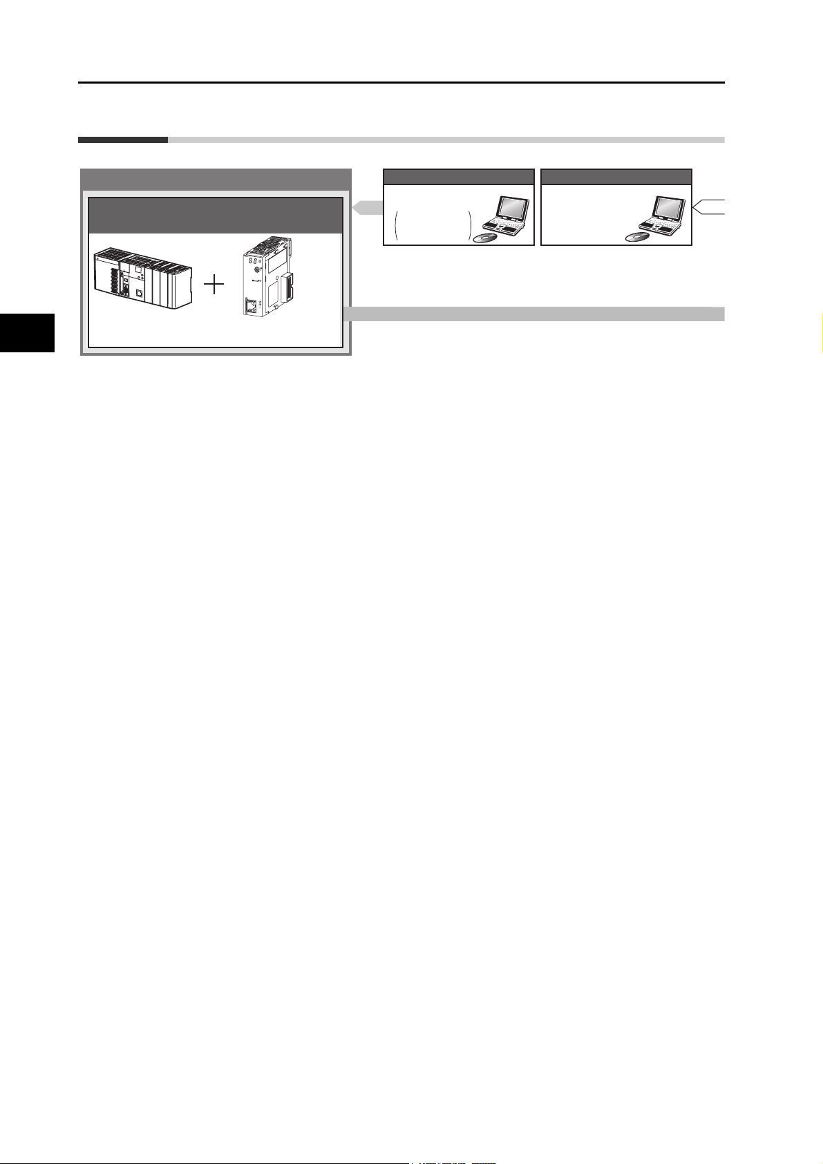
2
Controller
SYSMAC PLC Position Control Unit with EtherCAT Interface
Programmable
Controller
SYSMAC CJ2
Position Control Unit (NC)
CJ1W-NC@8@
Support Software
●
CX-One FA Integrated
Tool Package
CX-Programmer,
CX-Position,
and CX-Motion
Support Software
●
CX-One FA Integrated
Tool Package
(Including CX-Drive)
●
CX-Drive
WS02-DRVC1
Models and External Dimensions
2-1
OMNUC G5-series AC Servomotors and Servo Drives User’s Manual (with Built-in EtherCAT Communications)
Page 39

2-1 Servo System Configuration
communications
USB
EtherCAT
communications
AC Servo Drive
●
OMNUC G5-series Servo Drive
R88D-KN@-ECT-R
100 VAC
200 VAC
400 VAC
Motor power signals
Power Cables
●
Flexible Cables
•
Without Brake
R88A-CA@@@@@SR-E
•
With Brake
R88A-CA@@@@@BR-E
Brake Cables (50 to 750 W max.)
●
Flexible Cable
R88A-CAKA@@@BR-E
Feedback Signals
Encoder Cables
●
Flexible Cables
750 W or less:
•
R88A-CRKA@@@CR-E
•
1 kW or more:
R88A-CRKC@@@NR-E
AC Servomotors
●
OMNUC G5-series Servomotor
R88M-K
3000 r/min
2000 r/min
1000 r/min
2
Models and External Dimensions
External
encoder
Peripheral Devices
● External
Regeneration
Resistors
R88A-RR
Absolute Encoder Battery Cable
R88A-CRGD0R3C (-BS)
(A battery is included with model
numbers ending in “BS.”)
* Not required if a battery is connected to
the control connector (CN1).
OMNUC G5-series AC Servomotors and Servo Drives User’s Manual (with Built-in EtherCAT Communications)
2-2
Page 40

2-2 How to Read Model Numbers
2-2 How to Read Model Numbers
This section describes how to read and understand the model numbers of Servo Drives and
Servomotors.
Servo Drive
The Servo Drive model number tells the Servo Drive type, applicable Servomotor capacity,
power supply voltage, etc.
2
OMNUC G5-series
Servo Drive
Drive Type
N: Network
Maximum Applicable
Servomotor Capacity
A5
: 50 W
01: 100 W
02: 200 W
04: 400 W
06: 600 W
08: 750 W
10: 1 kW
15: 1.5 kW
20: 2 kW
30: 3 kW
50: 5 kW
Models and External Dimensions
Power Supply Voltage
L: 100 VAC
H: 200 VAC
F: 400 VAC
R88D-KN01H-ECT-R
2-3
Communications Type
ECT: EtherCAT
Model
R: Model limited to connection to CJ1W-NC@8@
OMNUC G5-series AC Servomotors and Servo Drives User’s Manual (with Built-in EtherCAT Communications)
Page 41

Servomotors
A
The model number provides information such as the Servomotor type, motor capacity, rated
rotation speed, and power supply voltage.
OMNUC G5-series Servomotor
2-2 How to Read Model Numbers
R88M-KP10030H-BOS2
Motor Type
Blank: Cylinder type
Servomotor Capacity
050: 50 W
100: 100 W
200: 200 W
400: 400 W
600: 600 W
750: 750 W
900: 900 W
1K0: 1 kW
1K5: 1.5 kW
2K0: 2 kW
3K0: 3 kW
4K0: 4 kW
5K0: 5 kW
Rated Rotation Speed
10: 1,000 r/min
20: 2,000 r/min
30: 3,000 r/min
pplied Voltage
F: 400 VAC (incremental encoder)
H: 200 VAC (incremental encoder)
L: 100 VAC (incremental encoder)
C: 400 VAC (absolute encoder)
T: 200 VAC (absolute encoder)
S: 100 VAC (absolute encoder)
2
Models and External Dimensions
Options
No: Straight shaft
B: With brake
O: With oil seal
S2: With key and tap
OMNUC G5-series AC Servomotors and Servo Drives User’s Manual (with Built-in EtherCAT Communications)
2-4
Page 42
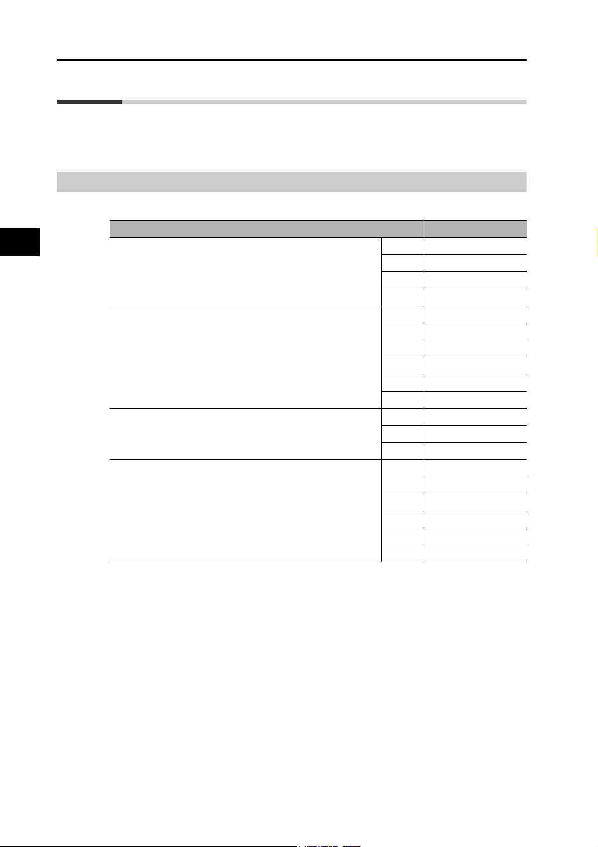
2
2-3 Model Tables
2-3 Model Tables
This section lists the standard models of Servo Drives, Servomotors, Cables, Connectors, and
peripheral equipment.
Servo Drive Model Table
The table below lists the Servo Drive models.
Specifications Model
Single-phase 100 VAC 50 W R88D-KNA5L-ECT-R
100 W R88D-KN01L-ECT-R
200 W R88D-KN02L-ECT-R
400 W R88D-KN04L-ECT-R
Single-phase/3-phase 200 VAC 100 W R88D-KN01H-ECT-R
200 W R88D-KN02H-ECT-R
400 W R88D-KN04H-ECT-R
3-phase 200 VAC 2 kW R88D-KN20H-ECT-R
3-phase 400 VAC 600 W R88D-KN06F-ECT-R
Models and External Dimensions
750 W R88D-KN08H-ECT-R
1 kW R88D-KN10H-ECT-R
1.5 kW R88D-KN15H-ECT-R
3 kW R88D-KN30H-ECT-R
5 kW R88D-KN50H-ECT-R
1 kW R88D-KN10F-ECT-R
1.5 kW R88D-KN15F-ECT-R
2 kW R88D-KN20F-ECT-R
3 kW R88D-KN30F-ECT-R
5 kW R88D-KN50F-ECT-R
2-5
OMNUC G5-series AC Servomotors and Servo Drives User’s Manual (with Built-in EtherCAT Communications)
Page 43
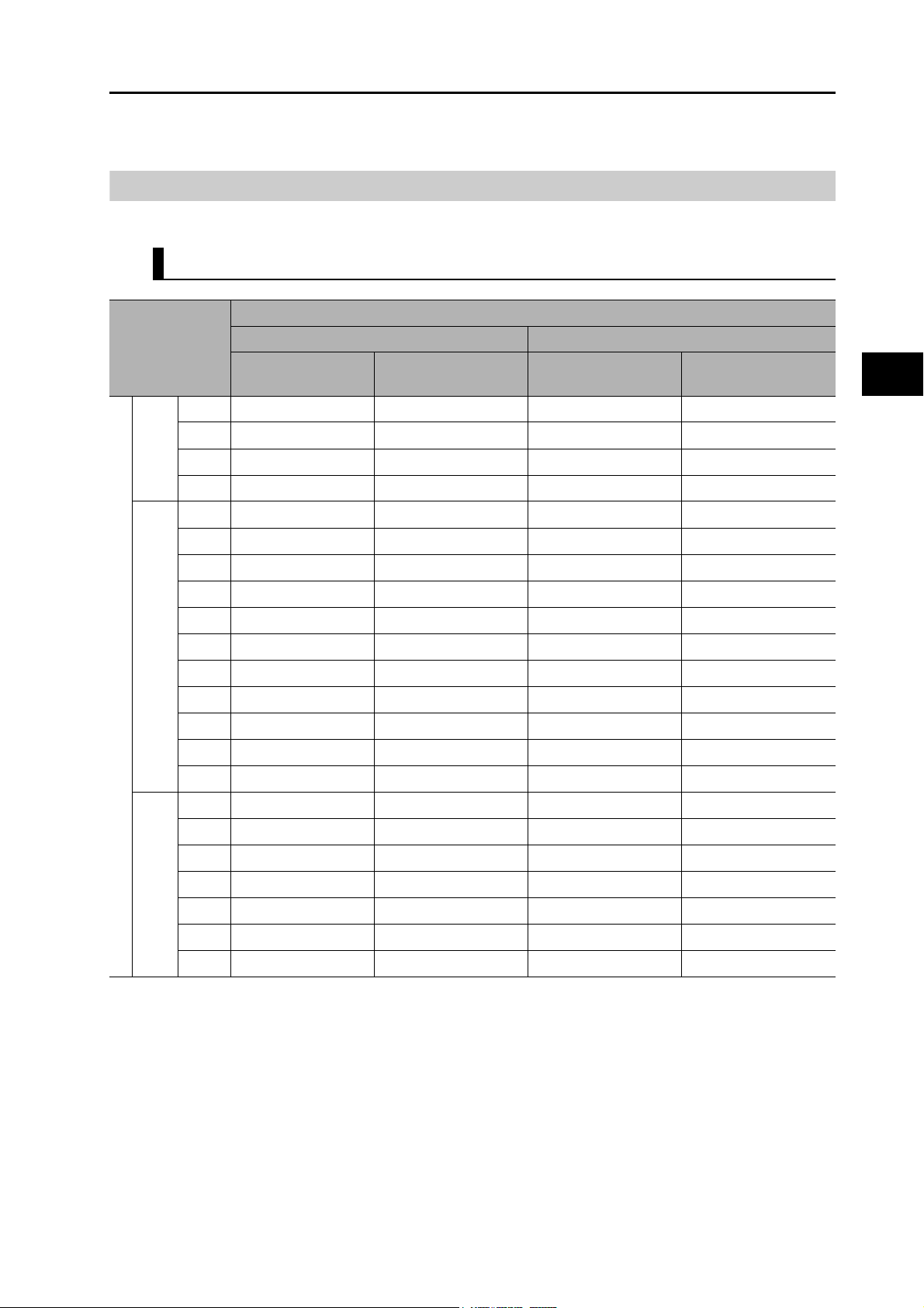
Servomotor Model Tables
The following tables list the Servomotor models by the rated motor speed.
3,000-r/min Servomotors
2-3 Model Tables
Model
Specifications
50 W R88M-K05030H R88M-K05030H-S2 R88M-K05030T R88M-K05030T-S2
100 W R88M-K10030L R88M-K10030L-S2 R88M-K10030S R88M-K10030S-S2
100 V
200 W R88M-K20030L R88M-K20030L-S2 R88M-K20030S R88M-K20030S-S2
400 W R88M-K40030L R88M-K40030L-S2 R88M-K40030S R88M-K40030S-S2
50 W R88M-K05030H R88M-K05030H-S2 R88M-K05030T R88M-K05030T-S2
100 W R88M-K10030H R88M-K10030H-S2 R88M-K10030T R88M-K10030T-S2
200 W R88M-K20030H R88M-K20030H-S2 R88M-K20030T R88M-K20030T-S2
400 W R88M-K40030H R88M-K40030H-S2 R88M-K40030T R88M-K40030T-S2
750 W R88M-K75030H R88M-K75030H-S2 R88M-K75030T R88M-K75030T-S2
200 V
Without brakes
1 kW R88M-K1K030H R88M-K1K030H-S2 R88M-K1K030T R88M-K1K030T-S2
1.5 kW R88M-K1K530H R88M-K1K530H-S2 R88M-K1K530T R88M-K1K530T-S2
2 kW R88M-K2K030H R88M-K2K030H-S2 R88M-K2K030T R88M-K2K030T-S2
3 kW R88M-K3K030H R88M-K3K030H-S2 R88M-K3K030T R88M-K3K030T-S2
4 kW R88M-K4K030H R88M-K4K030H-S2 R88M-K4K030T R88M-K4K030T-S2
5 kW R88M-K5K030H R88M-K5K030H-S2 R88M-K5K030T R88M-K5K030T-S2
750 W R88M-K75030F R88M-K75030F-S2 R88M-K75030C R88M-K75030C-S2
1 kW R88M-K1K030F R88M-K1K030F-S2 R88M-K1K030C R88M-K1K030C-S2
With incremental encoder With absolute encoder
Straight shaft
without key
Straight shaft
with key and tap
Straight shaft
without key
Straight shaft
with key and tap
2
Models and External Dimensions
1.5 kW R88M-K1K530F R88M-K1K530F-S2 R88M-K1K530C R88M-K1K530C-S2
400 V
OMNUC G5-series AC Servomotors and Servo Drives User’s Manual (with Built-in EtherCAT Communications)
2 kW R88M-K2K030F R88M-K2K030F-S2 R88M-K2K030C R88M-K2K030C-S2
3 kW R88M-K3K030F R88M-K3K030F-S2 R88M-K3K030C R88M-K3K030C-S2
4 kW R88M-K4K030F R88M-K4K030F-S2 R88M-K4K030C R88M-K4K030C-S2
5 kW R88M-K5K030F R88M-K5K030F-S2 R88M-K5K030C R88M-K5K030C-S2
2-6
Page 44

2-3 Model Tables
Model
2
Specifications
50 W R88M-K05030H-B R88M-K05030H-BS2 R88M-K05030T-B R88M-K05030T-BS2
100 V
200 V
With brakes
100 W R88M-K10030L-B R88M-K10030L-BS2 R88M-K10030S-B R88M-K10030S-BS2
200 W R88M-K20030L-B R88M-K20030L-BS2 R88M-K20030S-B R88M-K20030S-BS2
400 W R88M-K40030L-B R88M-K40030L-BS2 R88M-K40030S-B R88M-K40030S-BS2
50 W R88M-K05030H-B R88M-K05030H-BS2 R88M-K05030T-B R88M-K05030T-BS2
100 W R88M-K10030H-B R88M-K10030H-BS2 R88M-K10030T-B R88M-K10030T-BS2
200 W R88M-K20030H-B R88M-K20030H-BS2 R88M-K20030T-B R88M-K20030T-BS2
400 W R88M-K40030H-B R88M-K40030H-BS2 R88M-K40030T-B R88M-K40030T-BS2
750 W R88M-K75030H-B R88M-K75030H-BS2 R88M-K75030T-B R88M-K75030T-BS2
1 kW R88M-K1K030H-B R88M-K1K030H-BS2 R88M-K1K030T-B R88M-K1K030T-BS2
1.5 kW R88M-K1K530H-B R88M-K1K530H-BS2 R88M-K1K530T-B R88M-K1K530T-BS2
2 kW R88M-K2K030H-B R88M-K2K030H-BS2 R88M-K2K030T-B R88M-K2K030T-BS2
3 kW R88M-K3K030H-B R88M-K3K030H-BS2 R88M-K3K030T-B R88M-K3K030T-BS2
4 kW R88M-K4K030H-B R88M-K4K030H-BS2 R88M-K4K030T-B R88M-K4K030T-BS2
5 kW R88M-K5K030H-B R88M-K5K030H-BS2 R88M-K5K030T-B R88M-K5K030T-BS2
With incremental encoder With absolute encoder
Straight shaft
without key
Straight shaft
with key and tap
Straight shaft
without key
Straight shaft
with key and tap
750 W R88M-K75030F-B R88M-K75030F-BS2 R88M-K75030C-B R88M-K75030C-BS2
1 kW R88M-K1K030F-B R88M-K1K030F-BS2 R88M-K1K030C-B R88M-K1K030C-BS2
1.5 kW R88M-K1K530F-B R88M-K1K530F-BS2 R88M-K1K530C-B R88M-K1K530C-BS2
400 V
Models and External Dimensions
Note: Models with oil seals are also available.
2 kW R88M-K2K030F-B R88M-K2K030F-BS2 R88M-K2K030C-B R88M-K2K030C-BS2
3 kW R88M-K3K030F-B R88M-K3K030F-BS2 R88M-K3K030C-B R88M-K3K030C-BS2
4 kW R88M-K4K030F-B R88M-K4K030F-BS2 R88M-K4K030C-B R88M-K4K030C-BS2
5 kW R88M-K5K030F-B R88M-K5K030F-BS2 R88M-K5K030C-B R88M-K5K030C-BS2
2-7
OMNUC G5-series AC Servomotors and Servo Drives User’s Manual (with Built-in EtherCAT Communications)
Page 45

2,000-r/min Servomotors
Specifications
1 kW R88M-K1K020H R88M-K1K020H-S2 R88M-K1K020T R88M-K1K020T-S2
1.5 kW R88M-K1K520H R88M-K1K520H-S2 R88M-K1K520T R88M-K1K520T-S2
2 kW R88M-K2K020H R88M-K2K020H-S2 R88M-K2K020T R88M-K2K020T-S2
200 V
3 kW R88M-K3K020H R88M-K3K020H-S2 R88M-K3K020T R88M-K3K020T-S2
Model
With incremental encoder With absolute encoder
Straight shaft
without key
Straight shaft
with key and tap
Straight shaft
without key
2-3 Model Tables
Straight shaft
with key and tap
Without brakesWith brakes
4 kW R88M-K4K020H R88M-K4K020H-S2 R88M-K4K020T R88M-K4K020T-S2
5 kW R88M-K5K020H R88M-K5K020H-S2 R88M-K5K020T R88M-K5K020T-S2
400 W R88M-K40020F R88M-K40020F-S2 R88M-K40020C R88M-K40020C-BS2
600 W R88M-K60020F R88M-K60020F-S2 R88M-K60020C R88M-K60020C-BS2
1 kW R88M-K1K020F R88M-K1K020F-S2 R88M-K1K020C R88M-K1K020C-S2
1.5 kW R88M-K1K520F R88M-K1K520F-S2 R88M-K1K520C R88M-K1K520C-S2
400 V
2 kW R88M-K2K020F R88M-K2K020F-S2 R88M-K2K020C R88M-K2K020C-S2
3 kW R88M-K3K020F R88M-K3K020F-S2 R88M-K3K020C R88M-K3K020C-S2
4 kW R88M-K4K020F R88M-K4K020F-S2 R88M-K4K020C R88M-K4K020C-S2
5 kW R88M-K5K020F R88M-K5K020F-S2 R88M-K5K020C R88M-K5K020C-S2
1 kW R88M-K1K020H-B R88M-K1K020H-BS2 R88M-K1K020T-B R88M-K1K020T-BS2
1.5 kW R88M-K1K520H-B R88M-K1K520H-BS2 R88M-K1K520T-B R88M-K1K520T-BS2
2 kW R88M-K2K020H-B R88M-K2K020H-BS2 R88M-K2K020T-B R88M-K2K020T-BS2
200 V
3 kW R88M-K3K020H-B R88M-K3K020H-BS2 R88M-K3K020T-B R88M-K3K020T-BS2
4 kW R88M-K4K020H-B R88M-K4K020H-BS2 R88M-K4K020T-B R88M-K4K020T-BS2
5 kW R88M-K5K020H-B R88M-K5K020H-BS2 R88M-K5K020T-B R88M-K5K020T-BS2
400 W R88M-K40020F-B R88M-K40020F-BS2 R88M-K40020C-B R88M-K40020C-BS2
600 W R88M-K60020F-B R88M-K60020F-BS2 R88M-K60020C-B R88M-K60020C-BS2
1 kW R88M-K1K020F-B R88M-K1K020F-BS2 R88M-K1K020C-B R88M-K1K020C-BS2
1.5 kW R88M-K1K520F-B R88M-K1K520F-BS2 R88M-K1K520C-B R88M-K1K520C-BS2
400 V
2 kW R88M-K2K020F-B R88M-K2K020F-BS2 R88M-K2K020C-B R88M-K2K020C-BS2
3 kW R88M-K3K020F-B R88M-K3K020F-BS2 R88M-K3K020C-B R88M-K3K020C-BS2
4 kW R88M-K4K020F-B R88M-K4K020F-BS2 R88M-K4K020C-B R88M-K4K020C-BS2
2
Models and External Dimensions
5 kW R88M-K5K020F-B R88M-K5K020F-BS2 R88M-K5K020C-B R88M-K5K020C-BS2
Note: Models with oil seals are also available.
OMNUC G5-series AC Servomotors and Servo Drives User’s Manual (with Built-in EtherCAT Communications)
2-8
Page 46

2-3 Model Tables
1,000-r/min Servomotors
Model
2
Specifications
900 kW R88M-K90010H R88M-K90010H-S2 R88M-K90010T R88M-K90010T-S2
200 V
400 V
Without brakesWith brakes
200 V
400 V
Note: Models with oil seals are also available.
2 kW R88M-K2K010H R88M-K2K010H-S2 R88M-K2K010T R88M-K2K010T-S2
3 kW R88M-K3K010H R88M-K3K010H-S2 R88M-K3K010T R88M-K3K010T-S2
900 kW R88M-K90010F R88M-K90010F-S2 R88M-K90010C R88M-K90010C-S2
2 kW R88M-K2K010F R88M-K2K010F-S2 R88M-K2K010C R88M-K2K010C-S2
3 kW R88M-K3K010F R88M-K3K010F-S2 R88M-K3K010C R88M-K3K010C-S2
900 kW R88M-K90010H-B R88M-K90010H-BS2 R88M-K90010T-B R88M-K90010T-BS2
2 kW R88M-K2K010H-B R88M-K2K010H-BS2 R88M-K2K010T-B R88M-K2K010T-BS2
3 kW R88M-K3K010H-B R88M-K3K010H-BS2 R88M-K3K010T-B R88M-K3K010T-BS2
900 kW R88M-K90010F-B R88M-K90010F-BS2 R88M-K90010C-B R88M-K90010C-BS2
2 kW R88M-K2K010F-B R88M-K2K010F-BS2 R88M-K2K010C-B R88M-K2K010C-BS2
3 kW R88M-K3K010F-B R88M-K3K010F-BS2 R88M-K3K010C-B R88M-K3K010C-BS2
With incremental encoder With absolute encoder
Straight shaft
without key
Straight shaft
with key and tap
Straight shaft
without key
Straight shaft
with key and tap
Models and External Dimensions
2-9
OMNUC G5-series AC Servomotors and Servo Drives User’s Manual (with Built-in EtherCAT Communications)
Page 47

Servo Drive and Servomotor Combination Tables
The tables in this section show the possible combinations of OMNUC G5-series Servo Drives
and Servomotors. The Servomotors and Servo Drives can only be used in the listed
combinations.
“-@” at the end of the motor model number is for options, such as the shaft type, brake, oil seal
and key.
3,000-r/min Servomotors and Servo Drives
2-3 Model Tables
Servomotor
Voltage
Single-phase
100 V
Single-phase/
3-phase 100 V
Single-phase/
3-phase 200 V
3-phase 200 V 2 kW R88M-K2K030H-@ R88M-K2K030T-@ R88D-KN20H-ECT-R
Rated
output
50 W R88M-K05030H-@ R88M-K05030T-@ R88D-KNA5L-ECT-R
100 W R88M-K10030L-@ R88M-K10030S-@ R88D-KN01L-ECT-R
200 W R88M-K20030L-@ R88M-K20030S-@ R88D-KN02L-ECT-R
400 W R88M-K40030L-@ R88M-K40030S-@ R88D-KN04L-ECT-R
50 W R88M-K05030H-@ R88M-K05030T-@ R88D-KN01H-ECT-R*
100 W R88M-K10030H-@ R88M-K10030T-@ R88D-KN01H-ECT-R
200 W R88M-K20030H-@ R88M-K20030T-@ R88D-KN02H-ECT-R
400 W R88M-K40030H-@ R88M-K40030T-@ R88D-KN04H-ECT-R
750 W R88M-K75030H-@ R88M-K75030T-@ R88D-KN08H-ECT-R
1 kW R88M-K1K030H-@ R88M-K1K030T-@ R88D-KN15H-ECT-R*
1.5 kW R88M-K1K530H-@ R88M-K1K530T-@ R88D-KN15H-ECT-R
3 kW R88M-K3K030H-@ R88M-K3K030T-@ R88D-KN30H-ECT-R
4 kW R88M-K4K030H-@ R88M-K4K030T-@ R88D-KN50H-ECT-R
5 kW R88M-K5K030H-@ R88M-K5K030T-@ R88D-KN50H-ECT-R
With incremental
encoder
With absolute
encoder
Servo Drive
2
Models and External Dimensions
3-phase 400 V 750 W R88M-K75030F-@ R88M-K75030C-@ R88D-KN10F-ECT-R
1 kW R88M-K1K030F-@ R88M-K1K030C-@ R88D-KN15F-ECT-R*
1.5 kW R88M-K1K530F-@ R88M-K1K530C-@ R88D-KN15F-ECT-R
2 kW R88M-K2K030F-@ R88M-K2K030C-@ R88D-KN20F-ECT-R
3 kW R88M-K3K030F-@ R88M-K3K030C-@ R88D-KN30F-ECT-R
4 kW R88M-K4K030F-@ R88M-K4K030C-@ R88D-KN50F-ECT-R
5 kW R88M-K5K030F-@ R88M-K5K030C-@ R88D-KN50F-ECT-R
* Use these combination with caution because the Servo Drive and Servomotor have
different capacities.
OMNUC G5-series AC Servomotors and Servo Drives User’s Manual (with Built-in EtherCAT Communications)
2-10
Page 48

2-3 Model Tables
2,000-r/min Servomotors and Servo Drives
Voltage
Single-phase/
3-phase 200 V
3-phase 200 V 2 kW R88M-K2K020H-@ R88M-K2K020T-@ R88D-KN20H-ECT-R
Servomotor
Rated
output
1 kW R88M-K1K020H-@ R88M-K1K020T-@ R88D-KN10H-ECT-R
1.5 kW R88M-K1K520H-@ R88M-K1K520T-@ R88D-KN15H-ECT-R
3 kW R88M-K3K020H-@ R88M-K3K020T-@ R88D-KN30H-ECT-R
4 kW R88M-K4K020H-@ R88M-K4K020T-@ R88D-KN50H-ECT-R
With incremental
encoder
With absolute
encoder
Servo Drive
2
3-phase 400 V 400 W R88M-K40020F-@ R88M-K40020C-@ R88D-KN06F-ECT-R
1,000-r/min Servomotors and Servo Drives
Voltage
Models and External Dimensions
Single-phase/
3-phase 200 V
3-phase 200 V 2 kW R88M-K2K010H-@ R88M-K2K010T-@ R88D-KN30H-ECT-R*
3-phase 400 V 900 W R88M-K90010F-@ R88M-K90010C-@ R88D-KN15F-ECT-R*
5 kW R88M-K5K020H-@ R88M-K5K020T-@ R88D-KN50H-ECT-R
600 W R88M-K60020F-@ R88M-K60020C-@ R88D-KN06F-ECT-R
1 kW R88M-K1K020F-@ R88M-K1K020C-@ R88D-KN10F-ECT-R
1.5 kW R88M-K1K520F-@ R88M-K1K520C-@ R88D-KN15F-ECT-R
2 kW R88M-K2K020F-@ R88M-K2K020C-@ R88D-KN20F-ECT-R
3 kW R88M-K3K020F-@ R88M-K3K020C-@ R88D-KN30F-ECT-R
4 kW R88M-K4K020F-@ R88M-K4K020C-@ R88D-KN50F-ECT-R
5 kW R88M-K5K020F-@ R88M-K5K020C-@ R88D-KN50F-ECT-R
Servomotor
Rated
output
900 W R88M-K90010H-@ R88M-K90010T-@ R88D-KN15H-ECT-R*
3 kW R88M-K3K010H-@ R88M-K3K010T-@ R88D-KN50H-ECT-R*
With incremental
encoder
With absolute encoder
Servo Drive
2-11
2 kW R88M-K2K010F-@ R88M-K2K010C-@ R88D-KN30F-ECT-R*
3 kW R88M-K3K010F-@ R88M-K3K010C-@ R88D-KN50F-ECT-R*
* Use these combination with caution because the Servo Drive and Servomotor have
different capacities.
OMNUC G5-series AC Servomotors and Servo Drives User’s Manual (with Built-in EtherCAT Communications)
Page 49

Cable and Peripheral Device Model Tables
The following tables list the models of cables and peripheral devices. The cables include motor
power cables, brake cables, encoder cables, EtherCAT communications cables, and absolute
encoder battery cables. The peripheral devices include Connectors, External Regeneration
Resistors, and Mounting Brackets.
Encoder Cables (European Flexible Cables)
2-3 Model Tables
Specifications Model
[100 V and 200 V]
For 3,000-r/min Servomotors of 50 to 750 W
(for both absolute encoders and incremental encoders)
[100 V and 200 V]
3,000-r/min Servomotors of 1.0 kW or more
For 2,000-r/min Servomotors
For 1,000-r/min Servomotors
[400 V]
For 3,000-r/min Servomotors
For 2,000-r/min Servomotors
For 1,000-r/min Servomotors
1.5 m R88A-CRKA001-5CR-E
3 m R88A-CRKA003CR-E
5 m R88A-CRKA005CR-E
10 m R88A-CRKA010CR-E
15 m R88A-CRKA015CR-E
20 m R88A-CRKA020CR-E
1.5 m R88A-CRKC001-5NR-E
3 m R88A-CRKC003NR-E
5 m R88A-CRKC005NR-E
10 m R88A-CRKC010NR-E
15 m R88A-CRKC015NR-E
20 m R88A-CRKC020NR-E
2
Models and External Dimensions
OMNUC G5-series AC Servomotors and Servo Drives User’s Manual (with Built-in EtherCAT Communications)
2-12
Page 50

2-3 Model Tables
Motor Power Cables (European Flexible Cables)
[100 V and 200 V]
For 3,000-r/min Servomotors of 50 to
750 W
2
[200 V]
For 3,000-r/min Servomotors of 1 to
2 kW
For 2,000-r/min Servomotors of 1 to
2 kW
For 1,000-r/min Servomotors of 900 W
[400 V]
For 3,000-r/min Servomotors of 750 W
to 2 kW
For 2,000-r/min Servomotors of 400 W
to 2 kW
For 1,000-r/min Servomotors of 900 W
For 3,000-r/min Servomotors of 3 to
5kW
For 2,000-r/min Servomotors of 3 to
Models and External Dimensions
5kW
For 1,000-r/min Servomotors of 2 to
3kW
Specifications
Model
For motor without brake For motor with brake
1.5 m R88A-CAKA001-5SR-E (See note 1.)
3 m R88A-CAKA003SR-E
5 m R88A-CAKA005SR-E
10 m R88A-CAKA010SR-E
15 m R88A-CAKA015SR-E
20 m R88A-CAKA020SR-E
1.5 m R88A-CAGB001-5SR-E R88A-CAGB001-5BR-E
3 m R88A-CAGB003SR-E R88A-CAGB003BR-E
5 m R88A-CAGB005SR-E R88A-CAGB005BR-E
10 m R88A-CAGB010SR-E R88A-CAGB010BR-E
15 m R88A-CAGB015SR-E R88A-CAGB015BR-E
20 m R88A-CAGB020SR-E R88A-CAGB020BR-E
1.5 m R88A-CAGB001-5SR-E R88A-CAKF001-5BR-E
3 m R88A-CAGB003SR-E R88A-CAKF003BR-E
5 m R88A-CAGB005SR-E R88A-CAKF005BR-E
10 m R88A-CAGB010SR-E R88A-CAKF010BR-E
15 m R88A-CAGB015SR-E R88A-CAKF015BR-E
20 m R88A-CAGB020SR-E R88A-CAKF020BR-E
1.5 m R88A-CAGD001-5SR-E R88A-CAGD001-5BR-E
3 m R88A-CAGD003SR-E R88A-CAGD003BR-E
5 m R88A-CAGD005SR-E R88A-CAGD005BR-E
10 m R88A-CAGD010SR-E R88A-CAGD010BR-E
15 m R88A-CAGD015SR-E R88A-CAGD015BR-E
20 m R88A-CAGD020SR-E R88A-CAGD020BR-E
2-13
Note: It requires both, the power cable R88A-CAKA@@@SR-E and the separate brake cable R88A-
CAKA@@@BR-E. For the separate brake cable selection, see brake cables table in page 2-14.
OMNUC G5-series AC Servomotors and Servo Drives User’s Manual (with Built-in EtherCAT Communications)
Page 51

Brake Cables (European Flexible Cables)
Specifications Model
2-3 Model Tables
[100 V and 200 V]
For 3,000-r/min Servomotors of 50 to 750 W
Encoder Cables (Global Non-flexible Cables)
Specifications Model
[100 V and 200 V]
For 3,000-r/min Servomotors of 50 to 750 W
(for both absolute encoders and incremental encoders)
1.5 m R88A-CAKA001-5BR-E
3 m R88A-CAKA003BR-E
5 m R88A-CAKA005BR-E
10 m R88A-CAKA010BR-E
15 m R88A-CAKA015BR-E
20 m R88A-CAKA020BR-E
2
Models and External Dimensions
3 m R88A-CRKA003C
5 m R88A-CRKA005C
10 m R88A-CRKA010C
15 m R88A-CRKA015C
20 m R88A-CRKA020C
30 m R88A-CRKA030C
40 m R88A-CRKA040C
[100 V and 200 V]
3,000-r/min Servomotors of 1.0 kW or more
For 2,000-r/min Servomotors
For 1,000-r/min Servomotors
[400 V]
For 3,000-r/min Servomotors
For 2,000-r/min Servomotors
For 1,000-r/min Servomotors
50 m R88A-CRKA050C
3 m R88A-CRKC003N
5 m R88A-CRKC005N
10 m R88A-CRKC010N
15 m R88A-CRKC015N
20 m R88A-CRKC020N
30 m R88A-CRKC030N
40 m R88A-CRKC040N
50 m R88A-CRKC050N
OMNUC G5-series AC Servomotors and Servo Drives User’s Manual (with Built-in EtherCAT Communications)
2-14
Page 52

2-3 Model Tables
Motor Power Cables (Global Non-flexible Cables)
[100 V and 200 V]
For 3,000-r/min Servomotors of 50 to
750 W
Specifications
Model
For motor without
brake
3 m R88A-CAKA003S (See note 1.)
5 m R88A-CAKA005S
10 m R88A-CAKA010S
15 m R88A-CAKA015S
For motor with brake
2
[200 V]
For 3,000-r/min Servomotors of 1 to
2 kW
For 2,000-r/min Servomotors of 1 to
2 kW
For 1,000-r/min Servomotors of 900 W
[400 V]
For 3,000-r/min Servomotors of 750 W to
2 kW
For 2,000-r/min Servomotors of 400 W to
2 kW
Models and External Dimensions
For 1,000-r/min Servomotors of 900 W
20 m R88A-CAKA020S
30 m R88A-CAKA030S
40 m R88A-CAKA040S
50 m R88A-CAKA050S
3 m R88A-CAGB003S R88A-CAGB003B
5 m R88A-CAGB005S R88A-CAGB005B
10 m R88A-CAGB010S R88A-CAGB010B
15 m R88A-CAGB015S R88A-CAGB015B
20 m R88A-CAGB020S R88A-CAGB020B
30 m R88A-CAGB030S R88A-CAGB030B
40 m R88A-CAGB040S R88A-CAGB040B
50 m R88A-CAGB050S R88A-CAGB050B
3 m R88A-CAGB003S R88A-CAKF003B
5 m R88A-CAGB005S R88A-CAKF005B
10 m R88A-CAGB010S R88A-CAKF010B
15 m R88A-CAGB015S R88A-CAKF015B
20 m R88A-CAGB020S R88A-CAKF020B
30 m R88A-CAGB030S R88A-CAKF030B
40 m R88A-CAGB040S R88A-CAKF040B
50 m R88A-CAGB050S R88A-CAKF050B
2-15
For 3,000-r/min Servomotors of 3 to 5 kW
For 2,000-r/min Servomotors of 3 to 5 kW
For 1,000-r/min Servomotors of 2 to 3 kW
Note: It requires both, the power cable R88A-CAKA@@@S and the separate brake cable R88A-
CAKA@@@B. For the separate brake cable selection, see brake cables table in page 2-16.
OMNUC G5-series AC Servomotors and Servo Drives User’s Manual (with Built-in EtherCAT Communications)
3 m R88A-CAGD003S R88A-CAGD003B
5 m R88A-CAGD005S R88A-CAGD005B
10 m R88A-CAGD010S R88A-CAGD010B
15 m R88A-CAGD015S R88A-CAGD015B
20 m R88A-CAGD020S R88A-CAGD020B
30 m R88A-CAGD030S R88A-CAGD030B
40 m R88A-CAGD040S R88A-CAGD040B
50 m R88A-CAGD050S R88A-CAGD050B
Page 53

Brake Cables (Global Non-flexible Cables)
Specifications Model
2-3 Model Tables
[100 V and 200 V]
For 3,000-r/min Servomotors of 50 to 750 W
Encoder Cables (Global Flexible Cables)
Specifications Model
[100 V and 200 V]
For 3,000-r/min Servomotors of 50 to 750 W
(for both absolute encoders and incremental encoders)
3 m R88A-CAKA003B
5 m R88A-CAKA005B
10 m R88A-CAKA010B
15 m R88A-CAKA015B
20 m R88A-CAKA020B
30 m R88A-CAKA030B
40 m R88A-CAKA040B
50 m R88A-CAKA050B
3 m R88A-CRKA003CR
5 m R88A-CRKA005CR
10 m R88A-CRKA010CR
15 m R88A-CRKA015CR
20 m R88A-CRKA020CR
2
Models and External Dimensions
[100 V and 200 V]
3,000-r/min Servomotors of 1.0 kW or more
For 2,000-r/min Servomotors
For 1,000-r/min Servomotors
[400 V]
For 3,000-r/min Servomotors
For 2,000-r/min Servomotors
For 1,000-r/min Servomotors
30 m R88A-CRKA030CR
40 m R88A-CRKA040CR
50 m R88A-CRKA050CR
3 m R88A-CRKC003NR
5 m R88A-CRKC005NR
10 m R88A-CRKC010NR
15 m R88A-CRKC015NR
20 m R88A-CRKC020NR
30 m R88A-CRKC030NR
40 m R88A-CRKC040NR
50 m R88A-CRKC050NR
OMNUC G5-series AC Servomotors and Servo Drives User’s Manual (with Built-in EtherCAT Communications)
2-16
Page 54

2-3 Model Tables
Motor Power Cables (Global Flexible Cables)
[100 V and 200 V]
For 3,000-r/min Servomotors of 50 to
750 W
Specifications
Model
For motor without
brake
3 m R88A-CAKA003SR (See note 1.)
5 m R88A-CAKA005SR
10 m R88A-CAKA010SR
15 m R88A-CAKA015SR
For motor with brake
2
[200 V]
For 3,000-r/min Servomotors of 1 to 2 kW
For 2,000-r/min Servomotors of 1 to 2 kW
For 1,000-r/min Servomotors of 900 W
[400 V]
For 3,000-r/min Servomotors of 750 W to
2kW
For 2,000-r/min Servomotors of 400 W to
2kW
Models and External Dimensions
For 1,000-r/min Servomotors of 900 W
20 m R88A-CAKA020SR
30 m R88A-CAKA030SR
40 m R88A-CAKA040SR
50 m R88A-CAKA050SR
3 m R88A-CAGB003SR R88A-CAGB003BR
5 m R88A-CAGB005SR R88A-CAGB005BR
10 m R88A-CAGB010SR R88A-CAGB010BR
15 m R88A-CAGB015SR R88A-CAGB015BR
20 m R88A-CAGB020SR R88A-CAGB020BR
30 m R88A-CAGB030SR R88A-CAGB030BR
40 m R88A-CAGB040SR R88A-CAGB040BR
50 m R88A-CAGB050SR R88A-CAGB050BR
3 m R88A-CAGB003SR R88A-CAKF003BR
5 m R88A-CAGB005SR R88A-CAKF005BR
10 m R88A-CAGB010SR R88A-CAKF010BR
15 m R88A-CAGB015SR R88A-CAKF015BR
20 m R88A-CAGB020SR R88A-CAKF020BR
30 m R88A-CAGB030SR R88A-CAKF030BR
40 m R88A-CAGB040SR R88A-CAKF040BR
50 m R88A-CAGB050SR R88A-CAKF050BR
2-17
For 3,000-r/min Servomotors of 3 to 5 kW
For 2,000-r/min Servomotors of 3 to 5 kW
For 1,000-r/min Servomotors of 2 to 3 kW
Note: It requires both, the power cable R88A-CAKA@@@SR and the separate brake cable R88A-
CAKA@@@BR. For the separate brake cable selection, see brake cables table in page 2-18.
OMNUC G5-series AC Servomotors and Servo Drives User’s Manual (with Built-in EtherCAT Communications)
3 m R88A-CAGD003SR R88A-CAGD003BR
5 m R88A-CAGD005SR R88A-CAGD005BR
10 m R88A-CAGD010SR R88A-CAGD010BR
15 m R88A-CAGD015SR R88A-CAGD015BR
20 m R88A-CAGD020SR R88A-CAGD020BR
30 m R88A-CAGD030SR R88A-CAGD030BR
40 m R88A-CAGD040SR R88A-CAGD040BR
50 m R88A-CAGD050SR R88A-CAGD050BR
Page 55

Brake Cables (Global Flexible Cables)
Specifications Model
2-3 Model Tables
[100 V and 200 V]
For 3,000-r/min Servomotors of 50 to 750 W
3 m R88A-CAKA003BR
5 m R88A-CAKA005BR
10 m R88A-CAKA010BR
15 m R88A-CAKA015BR
20 m R88A-CAKA020BR
30 m R88A-CAKA030BR
40 m R88A-CAKA040BR
50 m R88A-CAKA050BR
EtherCAT Communications Cable (Recommended)
Category 5 or higher (cable with double, aluminum tape and braided shielding) is
recommended
Absolute Encoder Battery Cables
Name Model
Absolute Encoder Battery Cable (battery not supplied) 0.3 m R88A-CRGD0R3C
Absolute Encoder Battery Cable (R88A-BAT01G battery × 1 supplied) 0.3 m R88A-CRGD0R3C-BS
2
Models and External Dimensions
Absolute Encoder Backup Battery
Name Model
Absolute Encoder Backup Battery R88A-BAT01G
Analog Monitor Cable
Name Model
Analog Monitor Cable 1 m R88A-CMK001S
OMNUC G5-series AC Servomotors and Servo Drives User’s Manual (with Built-in EtherCAT Communications)
2-18
Page 56

2-3 Model Tables
Connectors
Name and applications Model
2
Motor Connector for Encoder Cable [100 V and 200 V]
For 3,000-r/min of 50 to 750 W
[100 V and 200 V]
For 3,000-r/min of 1 to 5 kW
For 2,000 r/min, 1,000 r/min
[400 V]
For 3,000 r/min, 2,000 r/min and
1,000 r/min
Control I/O Connector (CN1) R88A-CNW01C
Encoder Connector (CN2) R88A-CNW01R
External Encoder Connector (CN4) R88A-CNK41L
Safety Connector (CN8) R88A-CNK81S
Power Cable Connector (for 750 W max.) R88A-CNK11A
Brake Cable Connector (for 750 W max.) R88A-CNK11B
R88A-CNK02R
R88A-CNK04R
Control Cables
Name Model
Connector-terminal Block Cables 1 m XW2Z-100J-B34
2 m XW2Z-200J-B34
Connector-terminal Block M3 screws XW2B-20G4
Models and External Dimensions
External Regeneration Resistors
Regeneration process capacity: 20 W, 50 Ω (with 150°C thermal sensor) R88A-RR08050S
Regeneration process capacity: 20 W, 100 Ω (with 150°C thermal sensor) R88A-RR080100S
Regeneration process capacity: 70 W, 47 Ω (with 150°C thermal sensor) R88A-RR22047S1
Regeneration process capacity: 70 W, 47 Ω (with 170°C thermal sensor) R88A-RR22047S
Regeneration process capacity: 180 W, 20 Ω (with 200°C thermal sensor) R88A-RR50020S
M3.5 screws XW2B-20G5
M3 screws XW2D-20G6
Specifications Model
2-19
OMNUC G5-series AC Servomotors and Servo Drives User’s Manual (with Built-in EtherCAT Communications)
Page 57

2-3 Model Tables
Mounting Brackets (L-brackets for Rack Mounting)
Applicable Servo Drives Model
R88D-KNA5L-ECT-R/-KN01L-ECT-R/-KN01H-ECT-R/-KN02H-ECT-R R88A-TK01K
R88D-KN02L-ECT-R/-KN04H-ECT-R R88A-TK02K
R88D-KN04L-ECT-R/-KN08H-ECT-R R88A-TK03K
R88D-KN10H-ECT-R/-KN15H-ECT-R/-KN06F-ECT-R/-KN10F-ECT-R/-
KN15F-ECT-R
R88A-TK04K
2
Models and External Dimensions
OMNUC G5-series AC Servomotors and Servo Drives User’s Manual (with Built-in EtherCAT Communications)
2-20
Page 58
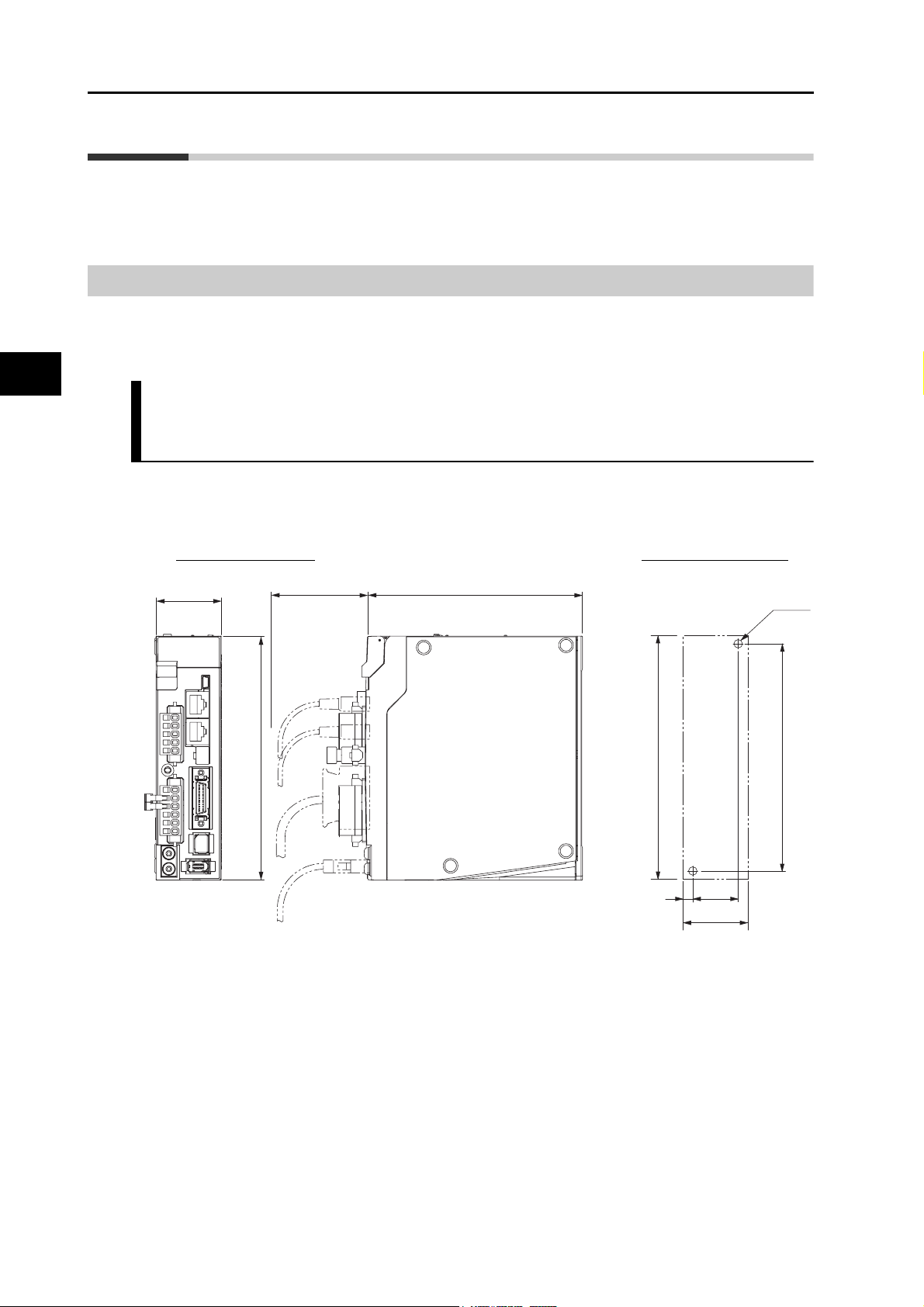
2
2-4 External and Mounting Dimensions
2-4 External and Mounting Dimensions
This section describes the external dimensions and the mounting dimensions of Servo Drives,
Servomotors, and peripheral devices.
Servo Drive Dimensions
The dimensional description starts with a Servo Drive of the smallest motor capacity, which is
followed by the next smallest, and so on.
Single-phase 100 VAC: R88D-KNA5L-ECT-R/-KN01L-ECT-R (50 to 100 W)
Single-phase/3-phase 200 VAC: R88D-KN01H-ECT-R/-KN02H-ECT-R
(100 to 200 W)
Wall Mounting
External dimensions Mounting dimensions
40
150
Models and External Dimensions
13270
150
6
28
40
φ5.2
140
2-21
OMNUC G5-series AC Servomotors and Servo Drives User’s Manual (with Built-in EtherCAT Communications)
Page 59
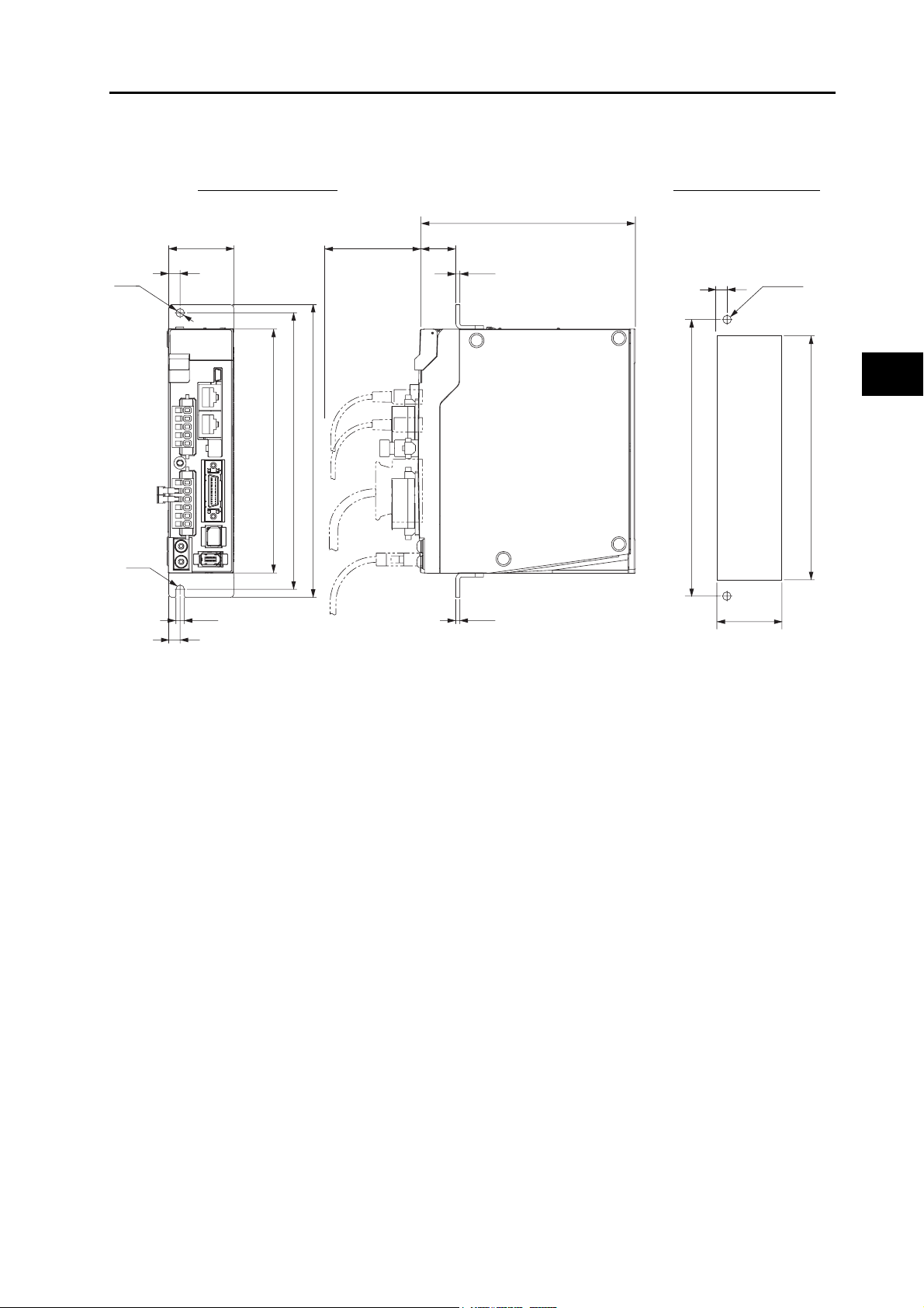
Front Mounting (Using Front Mounting Brackets)
External dimensions Mounting dimensions
19.5
φ5.2
40
7
180
170
150
70
2-4 External and Mounting Dimensions
132
2.5
170
7
Rectangular
φ5.2
hole
2
Models and External Dimensions
(158)*
R26
5.2
7
2.5
* Rectangular hole dimensions are reference values.
(42)*
OMNUC G5-series AC Servomotors and Servo Drives User’s Manual (with Built-in EtherCAT Communications)
2-22
Page 60

2-4 External and Mounting Dimensions
Single-phase/3-phase 100 VAC: R88D-KN02L-ECT-R (200 W)
Single-phase/3-phase 200 VAC: R88D-KN04H-ECT-R (400 W)
Wall Mounting
External dimensions Mounting dimensions
2
55
150
70
132
150
6
Front Mounting (Using Front Mounting Brackets)
External dimensions Mounting dimensions
φ5.2
140
43
55
Models and External Dimensions
φ5.2
R2.6
55
47
7
180
170
150
5.2
7
70
19.5
2.5
2.5
132
7
170
* Rectangular hole dimensions are reference values.
φ5.2
Rectangular
hole
(57)*
(158)*
2-23
OMNUC G5-series AC Servomotors and Servo Drives User’s Manual (with Built-in EtherCAT Communications)
Page 61

2-4 External and Mounting Dimensions
Single-phase/3-phase 100 VAC: R88D-KN04L-ECT-R (400 W)
Single-phase/3-phase 200 VAC: R88D-KN08H-ECT-R (750 W)
Wall Mounting
External dimensions Mounting dimensions
65
150
70
Front Mounting (Using Front Mounting Brackets)
External dimensions Mounting dimensions
70
19.5
2.5
φ5.2
65
40
20
172
172
4
φ5.2
2
Models and External Dimensions
150
7.5
4
50
65
20
140
φ5.2
180
170
150
R2.6
5.2
20
40
OMNUC G5-series AC Servomotors and Servo Drives User’s Manual (with Built-in EtherCAT Communications)
2.5
* Rectangular hole dimensions are reference values.
170
Rectangular
hole
(67)*
(158)*
2-24
Page 62
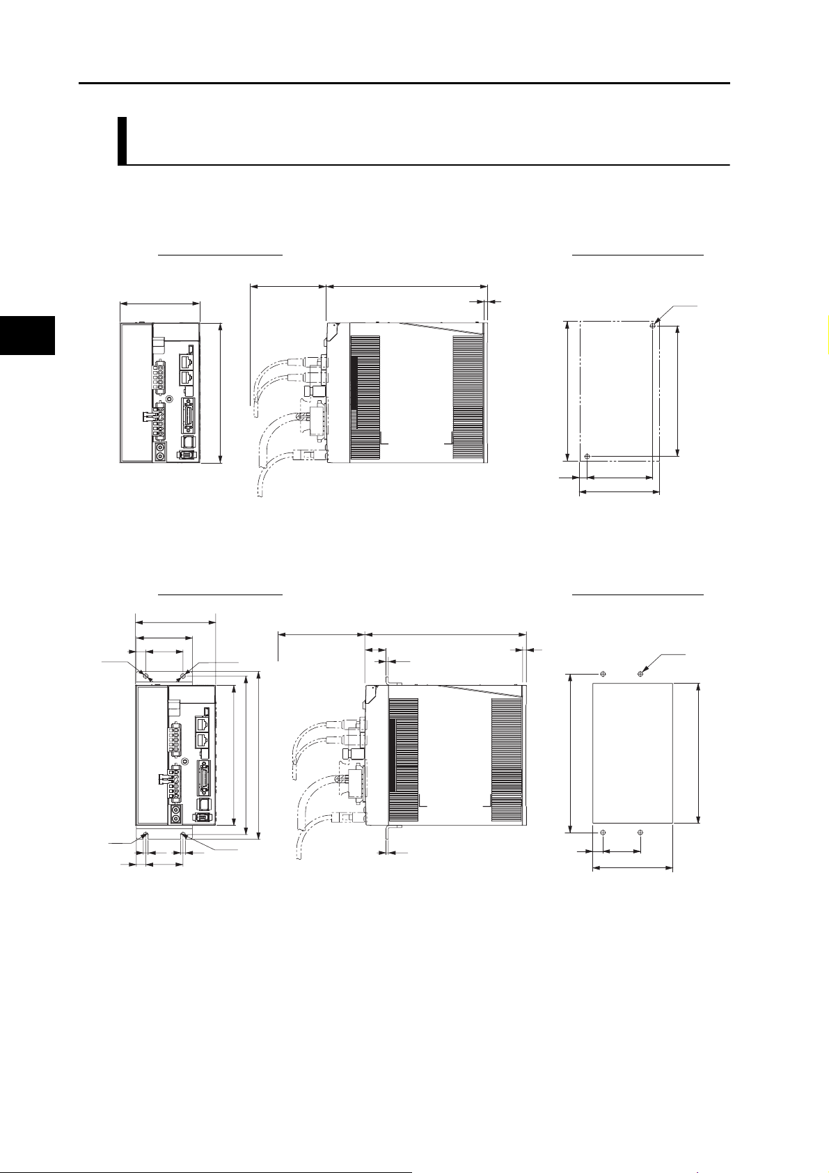
2-4 External and Mounting Dimensions
Single-phase/3-phase 200 VAC: R88D-KN10H-ECT-R/-KN15H-ECT-R
(900 W to 1.5 kW)
Wall Mounting
External dimensions Mounting dimensions
2
70
86
150
172
Front Mounting (Using Front Mounting Brackets)
External dimensions Mounting dimensions
φ5.2
86
60
10
40
φ5.2
70
19.5
2.5
172
4
150
8.5
4
70
86
φ5.2
140
φ5.2
Models and External Dimensions
170
180
150
R2.6
5.2
10
40
5.2
R2.6
2.5
Rectangular
40
hole
(88)*
(158)*
170
11
* Rectangular hole dimensions are reference values.
2-25
OMNUC G5-series AC Servomotors and Servo Drives User’s Manual (with Built-in EtherCAT Communications)
Page 63
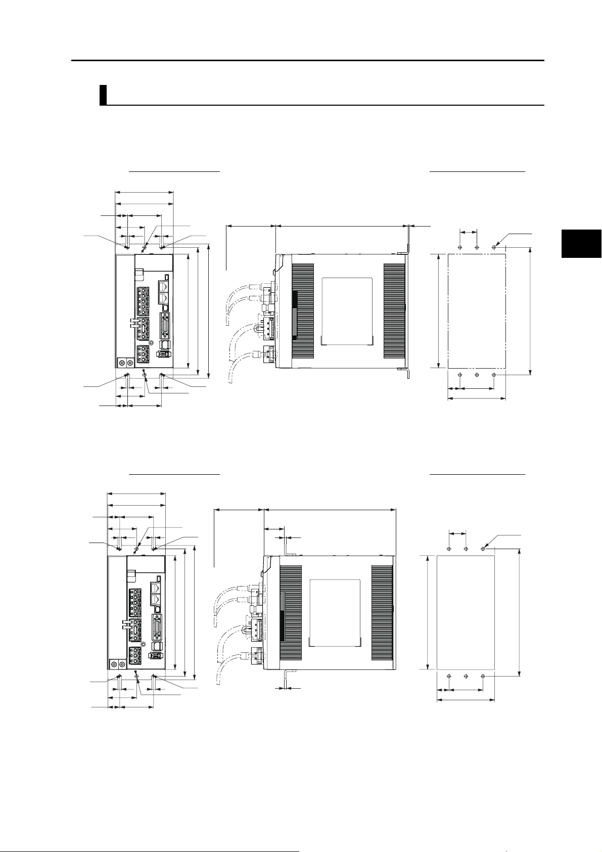
3-phase 200 VAC: R88D-KN20H-ECT-R (2 kW)
Wall Mounting
External dimensions Mounting dimensions
86
85
5017.5
R2.6 R2.6
42.5
5.2
5.2
φ5.2
168
188
70
198
2-4 External and Mounting Dimensions
195
1.8
168
25
φ5.2
188
2
Models and External Dimensions
R2.6
17.5
42.5
50
R2.6
5.25.2
φ5.2
Front Mounting (Using Front Mounting Brackets)
External dimensions Mounting dimensions
86
R2.6
42.5
5.2
85
5017.5
5.2
φ5.2
168
R2.6
188
198
70
30.7
2.5
195
17.5
(176)*
50
86
25
Rectangular
hole
φ5.2
188
R2.6
17.5
42.5
R2.6
5.25.2
φ5.2
50
2.5
17.5
(88)*
* Rectangular hole dimensions are reference values.
OMNUC G5-series AC Servomotors and Servo Drives User’s Manual (with Built-in EtherCAT Communications)
50
2-26
Page 64

2-4 External and Mounting Dimensions
3-phase 200 VAC: R88D-KN30H-ECT-R/-KN50H-ECT-R (3 to 5 kW)
Wall Mounting
External dimensions Mounting dimensions
2
70
250
R2.6
5.2
5.2
130
100
100
φ5.2
5.2
5.2
φ5.2
R2.6
220
R2.6R2.6
240
65
65
15
15
Front Mounting (Using Front Mounting Brackets)
External dimensions Mounting dimensions
214
3.5
220
50
15
100
130
φ5.2
240
5.2
5.2
130
100
100
φ5.2
5.2
5.2
φ5.2
R2.6
R2.6R2.6
220
240
250
65
65
Models and External Dimensions
15
R2.6
15
70
40.7
2.5
2.5
214
(228)*
Rectangular
15
50
hole
100
(132)*
φ5.2
240
* Rectangular hole dimensions
are reference values.
2-27
OMNUC G5-series AC Servomotors and Servo Drives User’s Manual (with Built-in EtherCAT Communications)
Page 65

2-4 External and Mounting Dimensions
3-phase 400 VAC: R88D-KN06F-ECT-R/-KN10F-ECT-R (600 W to 1.0 kW)
3-phase 400 VAC: R88D-KN15F-ECT-R (1.5 kW)
Wall Mounting
External dimensions Mounting dimensions
70
92
150
Front Mounting (Using Front Mounting Brackets)
External dimensions Mounting dimensions
92
60
10
φ5.2 φ5.2
40
70
19.5
2.5
172
172
4
φ5.2
2
Models and External Dimensions
150
14.5
4
70
92
140
φ5.2
170
180
150
6
R2.6
5.2 5.2
10
40
OMNUC G5-series AC Servomotors and Servo Drives User’s Manual (with Built-in EtherCAT Communications)
2.5
* Rectangular hole dimensions are reference values.
Rectangular
(158)*
18
hole
40
(94)*
170
2-28
Page 66

2
2-4 External and Mounting Dimensions
3-phase 400 VAC: R88D-KN20F-ECT-R (2 kW)
Wall Mounting
External dimensions Mounting dimensions
94
85
17.5
42.5
5.2
50
φ5.2
5.2
70
195 1.8
25
φ5.2
168
188
198
R2.6
5.2 5.2
17.5
50
φ5.2
R2.6
Front Mounting (Using Front Mounting Brackets)
External dimensions Mounting dimensions
94
85
17.5
Models and External Dimensions
42.5
5.2
50
φ5.2
5.2
168
188
198
168
50
26.5
94
70
30.7
2.5
195
25
Rectangular
(176)*
hole
180
φ5.2
180
2-29
R2.6
5.2 5.2
17.5
50
OMNUC G5-series AC Servomotors and Servo Drives User’s Manual (with Built-in EtherCAT Communications)
φ5.2
R2.6
2.5
50
26.5
(96)*
* Rectangular hole dimensions are reference values.
Page 67

2-4 External and Mounting Dimensions
3-phase 400 VAC: R88D-KN30F-ECT-R/-KN50F-ECT-R (3 to 5 kW)
Wall Mounting
External dimensions Mounting dimensions
15
R2.6
15
130
100
65
5.2 5.2
5.2
65
φ5.2
5.2
φ5.2
100
220
R2.6
240
70
250
Front Mounting (Using Front Mounting Brackets)
External dimensions Mounting dimensions
214
3.5
220
50
φ5.2
2
240
15
100
130
Models and External Dimensions
R2.6
15
15
130
100
65
5.2 5.2
5.2
65
φ5.2
5.2
φ5.2
100
220
R2.6
240
250
φ5.2
240
2.5
214
50
70
40.7
Rectangular
(228)*
15
2.5
hole
100
(132)*
* Rectangular hole dimensions are reference values.
OMNUC G5-series AC Servomotors and Servo Drives User’s Manual (with Built-in EtherCAT Communications)
2-30
Page 68

2-4 External and Mounting Dimensions
Servomotor Dimensions
In this description, the Servomotors are grouped by rated rotation speed. The description starts
with a Servomotor of the smallest capacity, which is followed by the next smallest, and so on.
3,000-r/min Servomotors (100 V and 200 V)
50 W/100 W (without Brake)
R88M-K05030H (-S2)/-K10030@ (-S2)
2
Models and External Dimensions
R88M-K05030T (-S2)/-K10030@ (-S2)
Encoder connector
Motor connector
LM
LN
Model
R88M-K05030@ 72 48 23
R88M-K10030@ 92 68 43
Note: The standard models have a straight shaft. Models with a key and tap are indicated with S2 at the
end of the model number.
25LL
63
2
1.5 min.
INC
ABS
40×40
R3.7
8h6
φ
φ30h7
Dimensions (mm)
LL LM LN
(Shaft end specifications with key and tap)
25
14
12.5
φ46±0.2
R4.2
2-φ4.3
3
6.2
3h9
M3 (depth 6)
2-31
OMNUC G5-series AC Servomotors and Servo Drives User’s Manual (with Built-in EtherCAT Communications)
Page 69

50 W/100 W (with Brake)
2-4 External and Mounting Dimensions
R88M-K05030H-B (S2)/-K10030@-B (S2)
R88M-K05030T-B (S2)/-K10030@-B (S2)
INC
ABS
Encoder connector
Brake connector
Motor connector
LL
LM
2
LN
25
36
1.5 min.
8h6
φ
φ30h7
R3.7
40×40
(Shaft end specifications with key and tap)
25
14
12.5
φ46±0.2
R4.2
2-φ4.3
3
6.2
3h9
M3 (depth 6)
Dimensions (mm)
Model
LL LM LN
R88M-K05030@-B@ 102 78 23
R88M-K10030@-B@ 122 98 43
Note: The standard models have a straight shaft. Models with a key and tap are indicated with S2 at the
end of the model number.
2
Models and External Dimensions
OMNUC G5-series AC Servomotors and Servo Drives User’s Manual (with Built-in EtherCAT Communications)
2-32
Page 70

2-4 External and Mounting Dimensions
200 W/400 W (without Brake)
2
R88M-K20030@ (-S2)/-K40030@ (-S2)
R88M-K20030@ (-S2)/-K40030@ (-S2)
INC
ABS
Encoder connector
Motor connector
LL
LM
6.5
30
3
1.5 min.
Sh6
φ
φ50h7
60×60
φ70±0.2
(Shaft end specifications with key and tap)
4-φ4.5
20 (200 W)
30
25 (400 W)
18 (200 W)
22.5 (400 W)
4h9 (200 W)
5h9 (400 W)
5 (400 W)
4 (200 W)
M4, depth 8 (200 W)
M5, depth 10 (400 W)
8.5
11
Dimensions (mm)
Model
LL LM S
R88M-K20030@ 79.5 56.5 11
R88M-K40030@ 99 76 14
Note: The standard models have a straight shaft. Models with a key and tap are indicated with S2 at the
end of the model number.
200 W/400 W (with Brake)
R88M-K20030@-B (S2)/-K40030@-B (S2)
R88M-K20030@-B (S2)/-K40030@-B (S2)
Models and External Dimensions
Encoder connector
Brake connector
Motor connector
LL
LM
6.5
Model
R88M-K20030@-B@ 116 93 11
R88M-K40030@-B@ 135.5 112.5 14
30
3
1.5 min.
INC
ABS
4-φ4.5
φSh6
φ50h7
Dimensions (mm)
LL LM S
60×60
(Shaft end specifications with key and tap)
20 (200 W)
30
φ70±0.2
25 (400 W)
18 (200 W)
22.5 (400 W)
4h9 (200 W)
5h9 (400 W)
5 (400 W)
4 (200 W)
M4, depth 8 (200 W)
M5, depth 10 (400 W)
8.5
11
2-33
Note: The standard models have a straight shaft. Models with a key and tap are indicated with S2 at the
end of the model number.
OMNUC G5-series AC Servomotors and Servo Drives User’s Manual (with Built-in EtherCAT Communications)
Page 71

750 W (without Brake)
2-4 External and Mounting Dimensions
R88M-K75030H (-S2)
R88M-K75030T (-S2)
INC
ABS
Encoder connector
Motor connector
112.2
86.2
83
35
80×80
(Shaft end specifications with key and tap)
4-φ6
35
25
22
6
15.5
φ19h6
φ90±0.2
φ70h7
Note: The standard models have a straight shaft. Models with a key and tap are indicated with S2 at the
end of the model number.
750 W (with Brake)
6h9
M5 (depth 10)
2
Models and External Dimensions
R88M-K75030H-B (S2)
R88M-K75030T-B (S2)
INC
ABS
Encoder connector
Brake connector
Motor connector
148.2
122.2
83
35
80×80
(Shaft end specifications with key and tap)
4-φ6
35
25
22
6h9
6
M5 (depth 10)
15.5
19h6
φ
φ90±0.2
φ70h7
Note: The standard models have a straight shaft. Models with a key and tap are indicated with S2 at the
end of the model number.
OMNUC G5-series AC Servomotors and Servo Drives User’s Manual (with Built-in EtherCAT Communications)
2-34
Page 72

2-4 External and Mounting Dimensions
1 kW/1.5 kW/2 kW (without Brake)
2
R88M-K1K030H (-S2)/-K1K530H (-S2)/-K2K030H (-S2)
R88M-K1K030T (-S2)/-K1K530T (-S2)/-K2K030T (-S2)
1 kW/1.5 kW/2 kW (with Brake)
R88M-K1K030H-B (S2)/-K1K530H-B (S2)/-K2K030H-B (-S2)
R88M-K1K030T-B (S2)/-K1K530T-B (S2)/-K2K030T-B (-S2)
Motor and brake
connector
Encoder
connector
101
60
R88M-K1K030@ 141 97 66 119
R88M-K1K530@ 159.5 115.5 84.5 137.5
R88M-K2K030@ 178.5 134.5 103.5 156.5
LM
KB2
KB1
Model
INC
ABS
INC
ABS
55LL
100×100
3
10
19h6
φ
φ95h7
Dimensions (mm)
LL LM KB1 KB2
(Shaft end specifications with key and tap)
55
4-φ9
φ135
φ115
45
42
M3, through
19h6
φ
φ95h7
15.5
6h9
6
M5 (depth 12)
R88M-K1K030@-B@ 168 124 66 146
R88M-K1K530@-B@ 186.5 142.5 84.5 164.5
R88M-K2K030@-B@ 205.5 161.5 103.5 183.5
Models and External Dimensions
Note: The standard models have a straight shaft. Models with a key and tap are indicated with S2 at the
end of the model number.
2-35
OMNUC G5-series AC Servomotors and Servo Drives User’s Manual (with Built-in EtherCAT Communications)
Page 73

3 kW (without Brake)
R88M-K3K030H (-S2)
R88M-K3K030T (-S2)
3 kW (with Brake)
R88M-K3K030H-B (S2)
R88M-K3K030T-B (S2)
2-4 External and Mounting Dimensions
INC
ABS
INC
ABS
Motor and brake
connector
Encoder
connector
LM
KB2
112
113
60
55LL
120×120
312
22h6
φ
φ110h7
(Shaft end specifications with key and tap)
55
45
4−φ9
φ162
φ145
41
M3, through
φ22h6
φ110h7
18
8h9
7
M5 (depth 12)
Dimensions (mm)
Model
LL LM KB2
R88M-K3K030@ 190 146 168
R88M-K3K030@-B@ 215 171 193
Note. The standard models have a straight shaft. Models with a key and tap are indicated with S2 at the
end of the model number.
2
Models and External Dimensions
OMNUC G5-series AC Servomotors and Servo Drives User’s Manual (with Built-in EtherCAT Communications)
2-36
Page 74

2-4 External and Mounting Dimensions
4 kW/5 kW (without Brake)
2
R88M-K4K030H (-S2)/-K5K030H (-S2)
R88M-K4K030T (-S2)/-K5K030T (-S2)
4 kW/5 kW (with Brake)
R88M-K4K030H-B (S2)/-K5K030H-B (S2)
R88M-K4K030T-B (S2)/-K5K030T-B (S2)
Motor and brake
connector
Encoder
connector
118
60
R88M-K4K030@ 208 164 127 186
Model
KB2
KB1
LM
INC
ABS
INC
ABS
65LL
130×130
612
24h6
φ
φ110h7
Dimensions (mm)
LL LM KB1 KB2
(Shaft end specifications with key and tap)
4−φ9
φ145
φ165
65
55
51
M3, through
φ24h6
φ110h7
20
8h9
7
M8 (depth 20)
R88M-K5K030@ 243 199 162 221
R88M-K4K030@-B@ 236 192 127 214
R88M-K5K030@-B@ 271 227 162 249
Note. The standard models have a straight shaft. Models with a key and tap are indicated with S2 at the
end of the model number.
Models and External Dimensions
2-37
OMNUC G5-series AC Servomotors and Servo Drives User’s Manual (with Built-in EtherCAT Communications)
Page 75
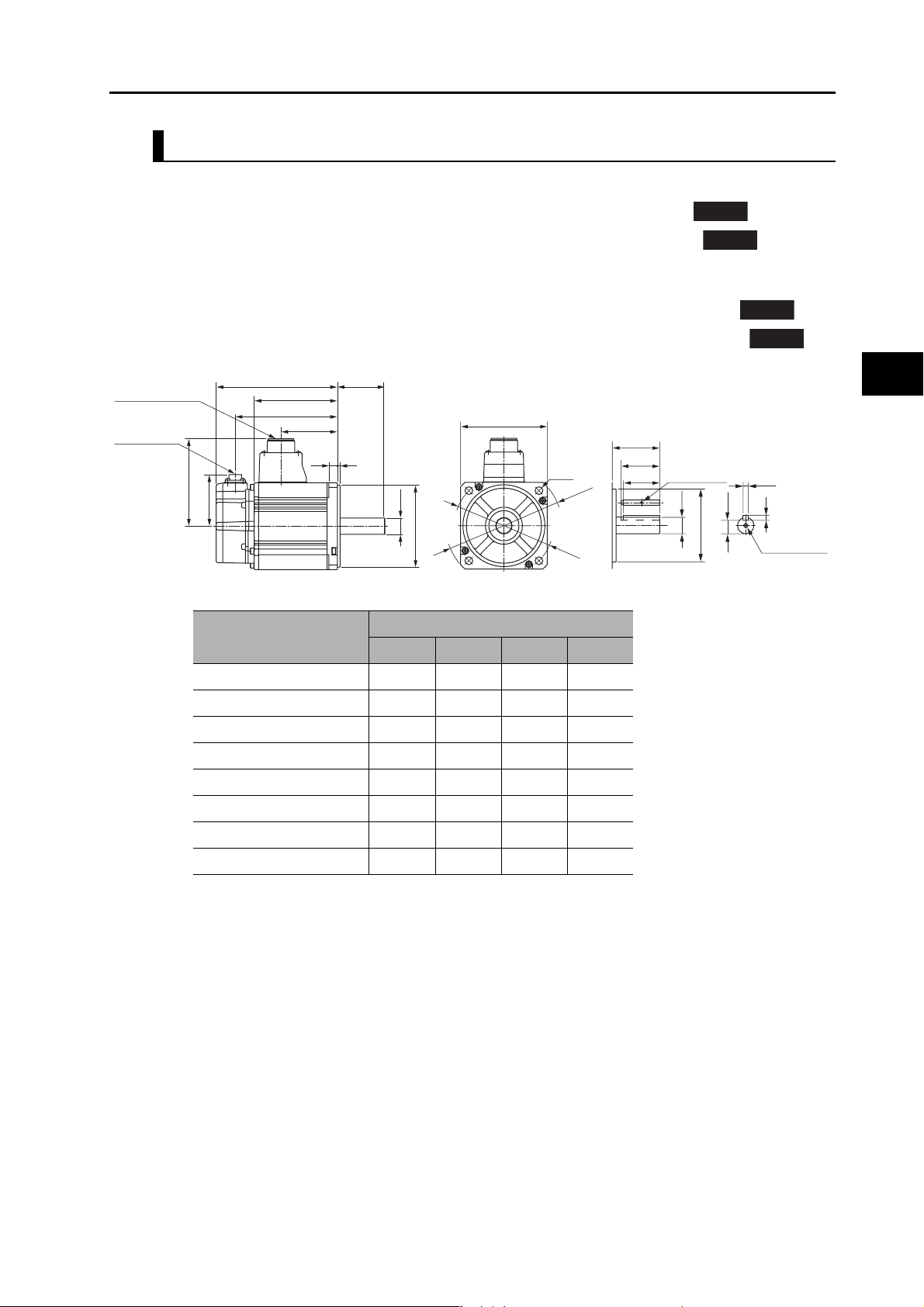
3,000-r/min Servomotors (400 V)
750 W/1 kW/1.5 kW/2 kW (without Brake)
2-4 External and Mounting Dimensions
R88M-K75030F (-S2)/-K1K030F (-S2)/-K1K530F (-S2)/-K2K030F (-S2)
R88M-K75030C (-S2)/-K1K030C (-S2)/-K1K530C (-S2)/-K2K030C (-S2)
750 W/1 kW/1.5 kW/2 kW (with Brake)
R88M-K75030F-B (S2)/-K1K030F-B (S2)/-K1K530F-B (S2)/-K2K030F-B (-S2)
R88M-K75030C-B (S2)/-K1K030C-B (S2)/-K1K530C-B (S2)/-K2K030C-B (-S2)
Motor and brake
connector
Encoder
connector
101 (without brake)
103 (with brake)
R88M-K75030@ 131.5 87.5 56.5 109.5
R88M-K1K030@ 141 97 66 119
LM
KB2
KB1
60
Model
55LL
310
19h6
φ
100×100
φ95h7
(Shaft end specifications with key and tap)
4-φ9
φ135
φ115
Dimensions (mm)
LL LM KB1 KB2
55
45
42
INC
ABS
M3, through
19h6
φ
φ95h7
15.5
INC
ABS
2
Models and External Dimensions
6h9
6
M5 (depth 12)
R88M-K1K530@ 159.5 115.5 84.5 137.5
R88M-K2K030@ 178.5 134.5 103.5 156.5
R88M-K75030@-B@ 158.5 114.5 53.5 136.5
R88M-K1K030@-B@ 168 124 63 146
R88M-K1K530@-B@ 186.5 142.5 81.5 164.5
R88M-K2K030@-B@ 205.5 161.5 100.5 183.5
Note: The standard models have a straight shaft. Models with a key and tap are indicated with S2 at the
end of the model number.
OMNUC G5-series AC Servomotors and Servo Drives User’s Manual (with Built-in EtherCAT Communications)
2-38
Page 76

2-4 External and Mounting Dimensions
3 kW (without Brake)
2
3 kW (with Brake)
Motor and brake
connector
Encoder
connector
113
0
R88M-K3K030F (-S2)
R88M-K3K030C (-S2)
R88M-K3K030F-B (S2)
R88M-K3K030C-B (S2)
LM
KB2
112
60
INC
ABS
INC
ABS
55LL
120×120
312
φ22h6
φ110h7
Dimensions (mm)
Model
LL LM KB2
R88M-K3K030@ 190 146 168
R88M-K3K030@-B@ 215 171 193
(Shaft end specifications with key and tap)
55
45
4-φ9
φ162
φ145
41
M3, through
φ22h6
φ110h7
18
8h9
7
M5 (depth 12)
Note. The standard models have a straight shaft. Models with a key and tap are indicated with S2 at the
end of the model number.
Models and External Dimensions
2-39
OMNUC G5-series AC Servomotors and Servo Drives User’s Manual (with Built-in EtherCAT Communications)
Page 77

4 kW/5 kW (without Brake)
2-4 External and Mounting Dimensions
R88M-K4K030F (-S2)/-K5K030F (-S2)
R88M-K4K030C (-S2)/-K5K030C (-S2)
4 kW/5 kW (with Brake)
R88M-K4K030F-B (S2)/-K5K030F-B (S2)
R88M-K4K030C-B (S2)/-K5K030C-B (S2)
Motor and brake
connector
Encoder
connector
118
60
R88M-K4K030@ 208 164 127 186
Model
LM
KB2
KB1
INC
ABS
INC
ABS
65LL
130×130
612
24h6
φ
φ110h7
Dimensions (mm)
LL LM KB1 KB2
(Shaft end specifications with key and tap)
4−φ9
φ145
φ165
65
55
51
M3, through
φ24h6
φ110h7
20
8h9
7
M8 (depth 20)
2
Models and External Dimensions
R88M-K5K030@ 243 199 162 221
R88M-K4K030@-B@ 236 192 127 214
R88M-K5K030@-B@ 271 227 162 249
Note. The standard models have a straight shaft. Models with a key and tap are indicated with S2 at the
end of the model number.
OMNUC G5-series AC Servomotors and Servo Drives User’s Manual (with Built-in EtherCAT Communications)
2-40
Page 78
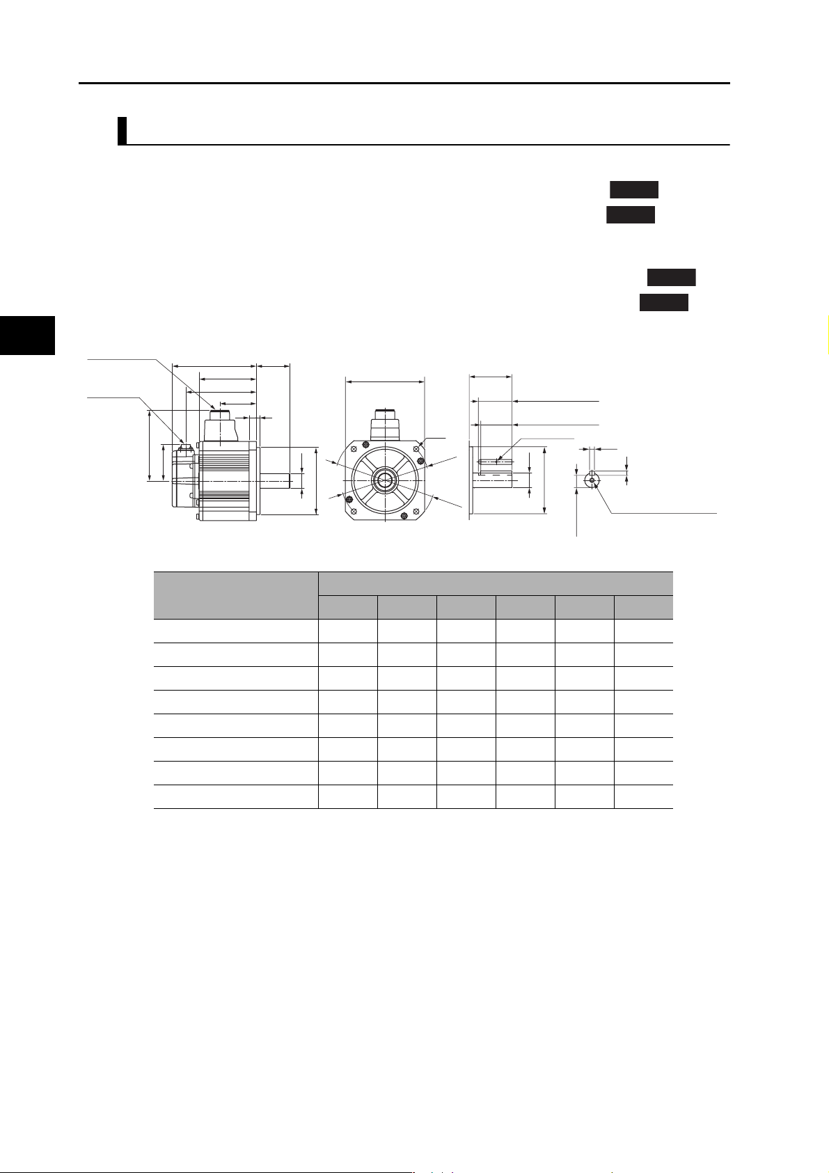
2-4 External and Mounting Dimensions
2,000-r/min Servomotors (200 V)
1 kW/1.5 kW/2 kW/3 kW (without Brake)
2
R88M-K1K020H (-S2)/-K1K520H (-S2)/-K2K020H (-S2)/-K3K020H (-S2)
R88M-K1K020T (-S2)/-K1K520T (-S2)/-K2K020T (-S2)/-K3K020T (-S2)
1 kW/1.5 kW/2 kW/3 kW (with Brake)
R88M-K1K020H-B (S2)/-K1K520H-B (S2)/-K2K020H-B (S2)/-K3K020H-B (S2)
R88M-K1K020T-B (S2)-K1K520T-B (S2)/-K2K020T-B (S2)/-K3K020T-B (S2)
Motor and brake
connector
Encoder
connector
LM
KB2
60
116 (1.0 to 2.0 kW)
118 (3.0 kW)
Model
R88M-K1K020@ 138 55 94 22 60 116
KB1
LRLL
612
Sh6
φ
(Shaft end specifications with key and tap)
LR
45 (1.0 to 2.0 kW)
55 (3.0 kW)
41 (1.0 to 2.0 kW)
51 (3.0 kW)
M3, through
φSh6
φ110h7
18 (1.0 to 2.0 kW)
20 (3.0 kW)
φ110h7
130×130
4−φ9
φ145
φ165
Dimensions (mm)
LL LR LM S KB1 KB2
INC
ABS
INC
ABS
8h9
7
M5, depth 12 (1.0 to 2.0 kW)
M8, depth 20 (3.0 kW)
R88M-K1K520@ 155.5 55 111.5 22 77.5 133.5
R88M-K2K020@ 173 55 129 22 95 151
Models and External Dimensions
R88M-K3K020@ 208 65 164 24 127 186
R88M-K1K020@-B@ 166 55 122 22 60 144
R88M-K1K520@-B@ 183.5 55 139.5 22 77.5 161.5
R88M-K2K020@-B@ 201 55 157 22 95 179
R88M-K3K020@-B@ 236 65 192 24 127 214
Note: The standard models have a straight shaft. Models with a key and tap are indicated with S2 at the
end of the model number.
2-41
OMNUC G5-series AC Servomotors and Servo Drives User’s Manual (with Built-in EtherCAT Communications)
Page 79
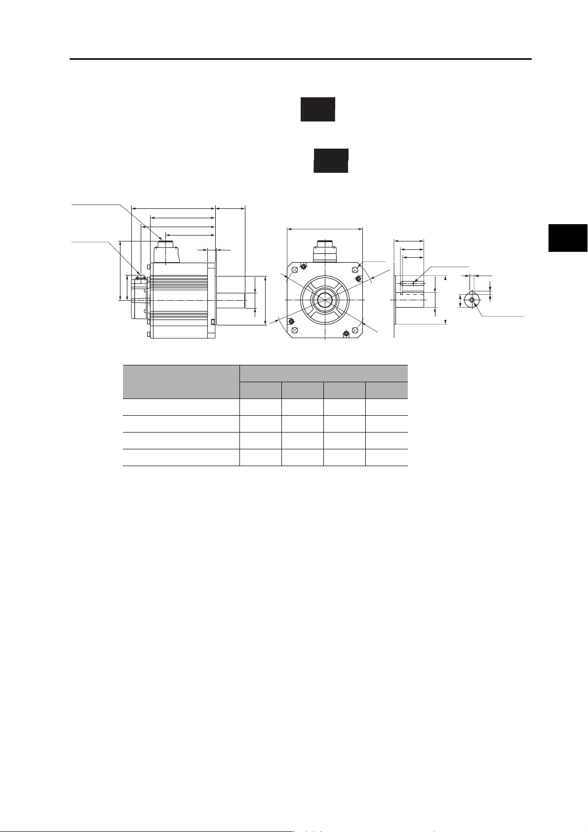
4 kW/5 kW (without Brake)
R88M-K4K020H (-S2)/-K5K020H (-S2)
R88M-K4K020T (-S2)/-K5K020T (-S2)
4 kW/5 kW (with Brake)
R88M-K4K020H-B (S2)/-K5K020H-B (S2)
R88M-K4K020T-B (S2)/-K5K020T-B (S2)
Motor and brake
connector
Encoder
connector
140
60
KB2
LM
KB1
2-4 External and Mounting Dimensions
INC
ABS
INC
ABS
70LL
176×176
3.218
35h6
φ
φ114.3h7
(Shaft end specifications with key and tap)
70
55
4−φ13.5
φ233
φ200
50
M3, through
10h9
φ35h6
30
φ114.3h7
8
M12 (depth 25)
2
Models and External Dimensions
Model
Dimensions (mm)
LL LM KB1 KB2
R88M-K4K020@ 177 133 96 155
R88M-K5K020@ 196 152 115 174
R88M-K4K020@-B@ 206 162 96 184
R88M-K5K020@-B@ 225 181 115 203
Note. The standard models have a straight shaft. Models with a key and tap are indicated with S2 at the
end of the model number.
OMNUC G5-series AC Servomotors and Servo Drives User’s Manual (with Built-in EtherCAT Communications)
2-42
Page 80

2-4 External and Mounting Dimensions
2,000-r/min Servomotors (400 V)
400 W/600 W (without Brake)
2
R88M-K40020F (-S2)/-K60020F (-S2)
R88M-K40020C (-S2)/-K60020C (-S2)
400 W/600 W (with Brake)
R88M-K40020F-B (S2)/-K60020F-B (S2)
R88M-K40020C-B (S2)/-K60020C-B (S2)
Motor and brake
connector
Encoder
connector
60
101 (without brake)
103 (with brake)
Model
R88M-K40020@ 131.5 87.5 56.5 109.5
KB2
LM
KB1
INC
ABS
INC
ABS
55LL
100×100
310
φ19h6
95h7
φ
Dimensions (mm)
LL LM KB1 KB2
(Shaft end specifications with key and tap)
55
45
M3, through
4-φ9
φ
φ
115
135
42
19h6
φ
95h7
φ
6h9
6
M5 (depth 12)
15.5
R88M-K60020@ 141 97 66 119
R88M-K40020@-B@ 158.5 114.5 53.5 136.5
R88M-K60020@-B@ 168 124 63 146
Models and External Dimensions
Note: The standard models have a straight shaft. Models with a key and tap are indicated with S2 at the
end of the model number.
2-43
OMNUC G5-series AC Servomotors and Servo Drives User’s Manual (with Built-in EtherCAT Communications)
Page 81

1 kW/1.5 kW/2 kW/3 kW (without Brake)
2-4 External and Mounting Dimensions
R88M-K1K020F (-S2)/-K1K520F (-S2)/-K2K020F (-S2)/-K3K020F (-S2)
R88M-K1K020C (-S2)/-K1K520C (-S2)/-K2K020C (-S2)/-K3K020C (-S2)
1 kW/1.5 kW/2 kW/3 kW (with Brake)
R88M-K1K020F-B (S2)/-K1K520F-B (S2)/-K2K020F-B (S2)/-K3K020F-B (S2)
R88M-K1K020C-B (S2)/-K1K520C-B (S2)/-K2K020C-B (S2)/-K3K020C-B (S2)
Motor and brake
connector
Encoder
connector
116 (1 to 2 kW/without brake)
118 (3 kW/without brake)
118 (1 to 3 kW/with brake)
LM
KB2
KB1
60
LRLL
612
φSh6
φ110h7
130×130
INC
ABS
INC
(Shaft end specifications with key and tap)
LR
45 (1 to 2 kW)
55 (3 kW)
41 (1 to 2 kW)
51 (3 kW)
4-φ9
φ145
φ165
M3, through
φSh6
φ110h7
8h9
M5, depth 12 (1.0 to 2.0 kW)
M8, depth 20 (3.0 kW)
18 (1 to 2 kW)
20 (3 kW)
7
ABS
2
Models and External Dimensions
Model
Dimensions (mm)
LL LR LM S KB1 KB2
R88M-K1K020@ 13855942260116
R88M-K1K520@ 155.5 55 111.5 22 77.5 133.5
R88M-K2K020@ 173 55 129 22 95 151
R88M-K3K020@ 208 65 164 24 127 186
R88M-K1K020@-B@ 166 55 122 22 57 144
R88M-K1K520@-B@ 183.5 55 139.5 22 74.5 161.5
R88M-K2K020@-B@ 201 55 157 22 92 179
R88M-K3K020@-B@ 236 65 192 24 127 214
Note: The standard models have a straight shaft. Models with a key and tap are indicated with S2 at the
end of the model number.
OMNUC G5-series AC Servomotors and Servo Drives User’s Manual (with Built-in EtherCAT Communications)
2-44
Page 82

2
2-4 External and Mounting Dimensions
4 kW/5 kW (without Brake)
R88M-K4K020F (-S2)/-K5K020F (-S2)
R88M-K4K020C (-S2)/-K5K020C (-S2)
4 kW/5 kW (with Brake)
R88M-K4K020F-B (S2)/-K5K020F-B (S2)
R88M-K4K020C-B (S2)/-K5K020C-B (S2)
Motor and brake
connector
Encoder
connector
LM
KB2
KB1
140
60
70LL
3.218
35h6
φ
φ114.3h7
INC
ABS
INC
ABS
176×176
(Shaft end specifications with key and tap)
70
55
4-φ13.5
φ233
φ200
50
M3, through
30
φ35h6
φ114.3h7
10h9
M12
(depth 25)
8
Model
R88M-K4K020@ 177 133 96 155
R88M-K5K020@ 196 152 115 174
R88M-K4K020@-B@ 206 162 96 184
R88M-K5K020@-B@ 225 181 115 203
Models and External Dimensions
Note. The standard models have a straight shaft. Models with a key and tap are indicated with S2 at the
end of the model number.
Dimensions (mm)
LL LM KB1 KB2
2-45
OMNUC G5-series AC Servomotors and Servo Drives User’s Manual (with Built-in EtherCAT Communications)
Page 83

1,000-r/min Servomotors (200 V)
900 W (without Brake)
2-4 External and Mounting Dimensions
R88M-K90010H (-S2)
R88M-K90010T (-S2)
900 W (with Brake)
R88M-K90010H-B (S2)
R88M-K90010T-B (S2)
Motor and brake
connector
Encoder
connector
116
60
KB2
LM
77.5
INC
ABS
INC
ABS
2
70LL
130×130
(Shaft end specifications with key and tap)
612
4-φ9
145
φ22h6
110 h7
φ
φ
φ
165
70
45
41
M3, through
φ22h6
110h7
φ
8h9
18
7
M5 (depth 12)
Models and External Dimensions
Model
Dimensions (mm)
LL LM KB2
R88M-K90010@ 155.5 111.5 133.5
R88M-K90010@-B@ 183.5 139.5 161.5
Note: The standard models have a straight shaft. Models with a key and tap are indicated with S2 at the
end of the model number.
OMNUC G5-series AC Servomotors and Servo Drives User’s Manual (with Built-in EtherCAT Communications)
2-46
Page 84

2
2-4 External and Mounting Dimensions
2 kW/3 kW (without Brake)
R88M-K2K010H (-S2)/-K3K010H (-S2)
R88M-K2K010T (-S2)/-K3K010T (-S2)
2 kW/3 kW (with Brake)
R88M-K2K010H-B (S2)/-K3K010H-B (S2)
R88M/-K2K010T-B (S2)/-K3K010T-B (S2)
Motor and brake
connector
Encoder
connector
140
60
LL
KB2
LM
KB1
80
3.218
35h6
φ
φ114.3h7
INC
ABS
176×176
INC
ABS
(Shaft end specifications with key and tap)
80
55
4−φ13.5
φ233
φ200
50
M3, through
φ35h6
30
φ114.3h7
10h9
8
M12 (depth 25)
Model
R88M-K2K010@ 163.5 119.5 82.5 141.5
R88M-K3K010@ 209.5 165.5 128.5 187.5
R88M-K2K010@-B@ 192.5 148.5 82.5 170.5
R88M-K3K010@-B@ 238.5 194.5 128.5 216.5
Note. The standard models have a straight shaft. Models with a key and tap are indicated with S2 at the
Models and External Dimensions
end of the model number.
Dimensions (mm)
LL LM KB1 KB2
2-47
OMNUC G5-series AC Servomotors and Servo Drives User’s Manual (with Built-in EtherCAT Communications)
Page 85

1,000-r/min Servomotors (400 V)
900 W (without Brake)
2-4 External and Mounting Dimensions
R88M-K90010F (-S2)
R88M-K90010C (-S2)
900 W (with Brake)
R88M-K90010F-B (S2)
R88M-K90010C-B (S2)
Motor and brake
connector
Encoder
connector
60
116 (without brake)
118 (with brake)
KB2
LM
KB1
INC
ABS
INC
ABS
2
70LL
130×130
612
φ22h6
110h7
φ
(Shaft end specifications with key and tap)
70
45
41
4-φ9
φ
145
φ
165
M3, through
φ22h6
110h7
φ
8h9
18
7
M5 (depth 12)
Models and External Dimensions
Model
Dimensions (mm)
LL LM KB1 KB2
R88M-K90010@ 155.5 111.5 77.5 133.5
R88M-K90010@-B@ 183.5 139.5 74.5 161.5
Note: The standard models have a straight shaft. Models with a key and tap are indicated with S2 at the
end of the model number.
OMNUC G5-series AC Servomotors and Servo Drives User’s Manual (with Built-in EtherCAT Communications)
2-48
Page 86

2
2-4 External and Mounting Dimensions
2 kW/3 kW (without Brake)
R88M-K2K010F (-S2)/-K3K010F (-S2)
R88M-K2K010C (-S2)/-K3K010C (-S2)
2 kW/3 kW (with Brake)
R88M-K2K010F-B (S2)/-K3K010F-B (S2)
R88M-K2K010C-B (S2)/-K3K010C-B (S2)
Motor and brake
connector
Encoder
connector
LM
KB2
KB1
140
60
80LL
3.218
35h6
φ
φ114.3h7
INC
ABS
176×176
INC
ABS
(Shaft end specifications with key and tap)
80
55
4−φ13.5
φ233
φ200
50
M3, through
φ35h6
30
φ114.3h7
10h9
8
M12 (depth 25)
Model
R88M-K2K010@ 163.5 119.5 82.5 141.5
R88M-K3K010@ 209.5 165.5 128.5 187.5
R88M-K2K010@-B@ 192.5 148.5 82.5 170.5
R88M-K3K010@-B@ 238.5 194.5 128.5 216.5
Note. The standard models have a straight shaft. Models with a key and tap are indicated with S2 at the
Models and External Dimensions
end of the model number.
Dimensions (mm)
LL LM KB1 KB2
2-49
OMNUC G5-series AC Servomotors and Servo Drives User’s Manual (with Built-in EtherCAT Communications)
Page 87
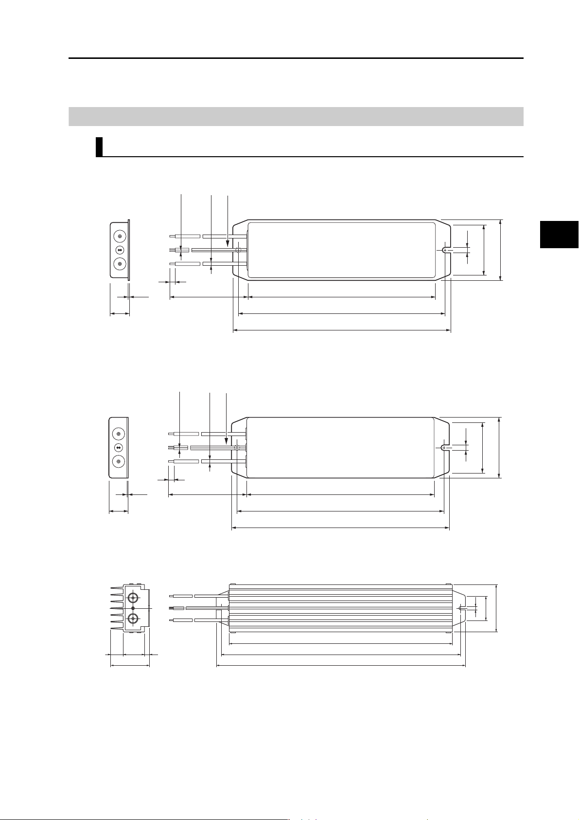
2-4 External and Mounting Dimensions
External Regeneration Resistor Dimensions
External Regeneration Resistor
R88A-RR08050S/-RR080100S
Thermal switch output
)
2
)
2
ϕ1.5
(0.3 mm
ϕ3
(0.75 mm
4.2
28
2
43.5
6
t1.2 104
20
500
R88A-RR22047S/-RR22047S1
Thermal switch output
)
2
)
2
ϕ1.5
(0.3 mm
ϕ3
(0.75 mm
6
t1.2 200
20
500
122
130
220
230
4.2
48
Models and External Dimensions
62
R88A-RR50020S
360
4325 10
78
OMNUC G5-series AC Servomotors and Servo Drives User’s Manual (with Built-in EtherCAT Communications)
386
402
5.2
40
76
2-50
Page 88

2-5 EMC Filter Dimensions
2-5 EMC Filter Dimensions
2
W
M2
Drive
mounts
M1
H
Output
flexes
Filter model
R88A-FIK102-RE 190 42 44 180 20
R88A-FIK104-RE 190 57 30 180 30
R88A-FIK107-RE 190 64 35 180 40
R88A-FIK114-RE 190 86 35 180 60
R88A-FIK304-RE 190 86 40 180 60
External dimensions Mount dimensions
H W D M1 M2
D
R88A-FIK306-RE 245 94 40 235 60
R88A-FIK312-RE 290 130 45 280 100
Models and External Dimensions
2-51
OMNUC G5-series AC Servomotors and Servo Drives User’s Manual (with Built-in EtherCAT Communications)
Page 89

Specifications
This chapter provides the general specifications, characteristics, connector
specifications, and I/O circuits of the Servo Drives as well as the general
specifications, characteristics, encoder specifications of the Servomotors and
other peripheral devices.
3-1 Servo Drive Specifications ..........................................3-1
3-2 Overload Characteristics
(Electronic Thermal Function)...................................3-31
3-3 Servomotor Specifications ........................................3-32
3-4 Cable and Connector Specifications ........................3-57
3-5 External Regeneration Resistor Specifications.......3-80
3-6 EMC Filter Specifications...........................................3-82
3
OMNUC G5-series AC Servomotors and Servo Drives User’s Manual (with Built-in EtherCAT Communications)
Page 90
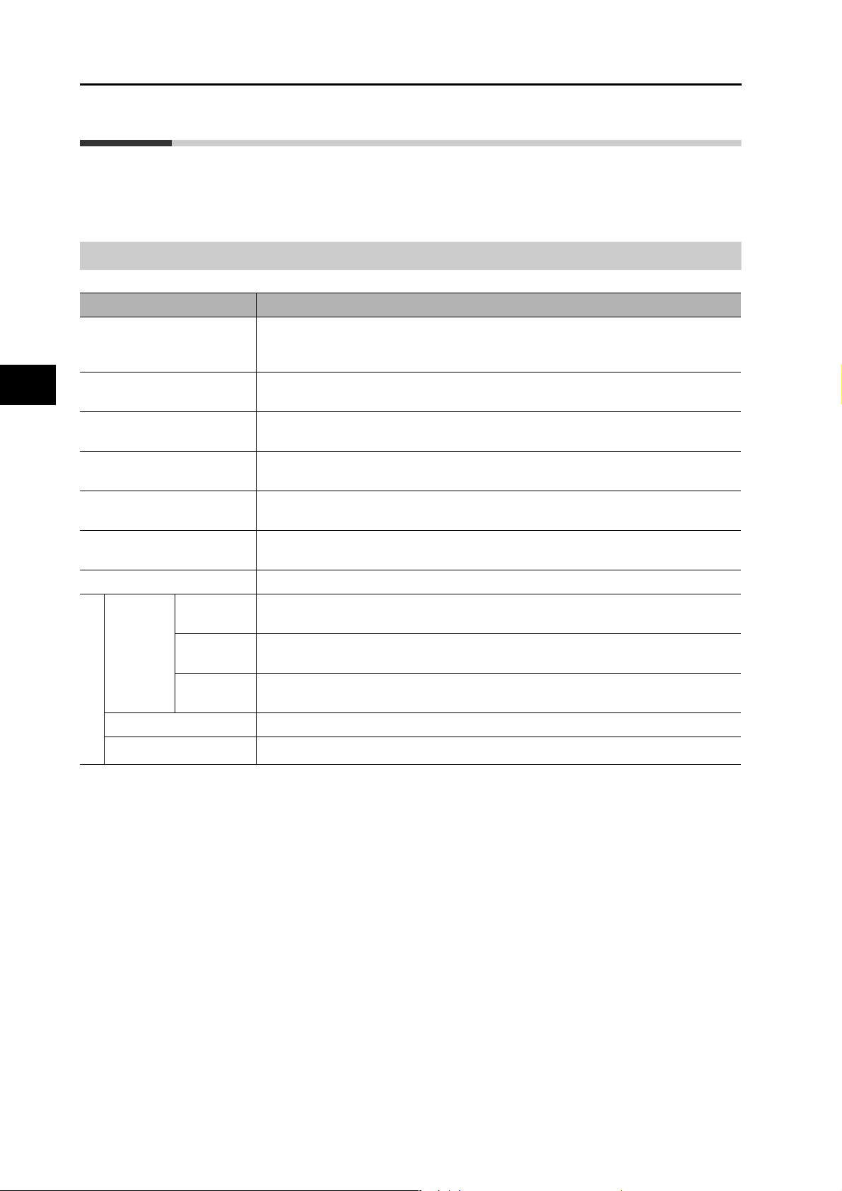
3-1 Servo Drive Specifications
3-1 Servo Drive Specifications
General Specifications
Ambient operating
temperature and operating
humidity
3
Specifications
Storage ambient temperature
and humidity
Operating and storage
atmosphere
Vibration resistance 10 to 60 Hz and at an acceleration of 5.88 m/s
Insulation resistance Between power supply terminals/power terminals and FG terminal: 0.5 MΩ min. (at
Dielectric strength Between power supply/power line terminals and FG terminal: 1,500 VAC for 1 min at
Protective structure Built into panel
Item Specifications
EC
Directives
Select a Servo Drive that matches the Servomotor to be used. Refer to Servo Drive and
Servomotor Combination Tables on page 2-10.
0 to 55°C, 90% max. (with no condensation)
−20 to 65°C, 90% max. (with no condensation)
No corrosive gases
2
or less (Not to be run continuously at
a resonance point)
500 VDC)
50/60 Hz
EMC
Directive
Low Voltage
Directive
EN 55011, EN 61000-6-2, IEC 61800-3
EN 61800-5-1
Machinery
Directive
UL standards UL 508C
International standard
CSA standards CSA22.2 No. 14
Note 1. The above items reflect individual evaluation testing. The results may differ under compound conditions.
Note 2. Never perform dielectric strength or other megameter tests on the Servo Drive. Failure to follow this guideline
may result in damaging the internal elements.
Note 3. Depending on the operating conditions, some Servo Drive parts will require maintenance. For details, refer to
12-5 Periodic Maintenance on page 12-31.
EN954-1 (Category 3), EN ISO 13849-1: 2008 (PLc,d), ISO 13849-1: 2006 (PLc,d),
EN61508 (SIL2), EN62061 (SIL2), EN61800-5-2 (STO), IEC61326-3-1 (SIL2)
3-1
OMNUC G5-series AC Servomotors and Servo Drives User’s Manual (with Built-in EtherCAT Communications)
Page 91

Characteristics
100-VAC Input Models
3-1 Servo Drive Specifications
Item
Continuous output current (rms) 1.2 A 1.7 A 2.5 A 4.6 A
Input power
supply
Control method All-digital servo
Inverter method IGBT-driven PWM
PWM frequency 12.0 kHz 6.0 kHz
Weight Approx. 0.8 kg Approx. 0.8 kg Approx. 1.0 kg Approx. 1.6 kg
Maximum applicable motor capacity 50 W 100 W 200 W 400 W
Main
circuit
Control
circuit
Power
supply
capacity
Power
supply
voltage
Rated
current
Heat
*1
value
Power
supply
voltage
Heat
*1
value
R88D-
KNA5L-ECT-R
0.4 KVA 0.4 KVA 0.5 KVA 0.9 KVA
Single-phase 100 to 120 VAC (85 to 132 V) 50/60 Hz
1.7 A 2.6 A 4.3 A 7.6 A
11 W 16.6 W 21 W 25 W
Single-phase 100 to 120 VAC (85 to 132 V) 50/60 Hz
6 W6 W6 W6 W
R88D-
KN01L-ECT-R
R88D-
KN02L-ECT-R
R88D-
KN04L-ECT-R
3
Specifications
Applicable
Servomotor
*1. The heat value is given for rated operation.
OMNUC G5-series AC Servomotors and Servo Drives User’s Manual (with Built-in EtherCAT Communications)
3,000
r/min
2,000
r/min
1,000
r/min
INC
ABS
ABS
ABS
K05030H K10030L K20030L K40030L
K05030T K10030S K20030S K40030S
−−−−
−−−−
3-2
Page 92

3-1 Servo Drive Specifications
200-VAC Input Models
Continuous output current (rms) 1.2 A 1.6 A 2.6 A 4.1 A 5.9 A 9.4 A
Input power
supply
3
PWM frequency 12.0 kHz 6.0 kHz
Weight Approx.
Specifications
Maximum applicable motor
capacity
Item
Main
circuit
Control
circuit
Power
supply
capacity
Power
supply
voltage
Rated
current
Heat
*2
value
Power
supply
voltage
Heat
*2
value
R88D-
KN01H-
ECT-R
0.5 KVA 0.5 KVA 0.9 KVA 1.3 KVA 1.8 KVA 2.3KVA
Single-phase or 3-phase 200 to 240 VAC (170 to 264 V) 50/60 Hz
1.6/0.9 A *
14.3/13.7 W *123/19 W *130/22 W *130/35.5 W *163/64 W *1104/93 W *
6 W 6 W6 W6 W8 W8 W
0.8 kg
100 W 200 W 400 W 750 W 1 kW 1.5 kW
R88D-
KN02H-
ECT-R
1
2.4/1.3 A*14.1/2.4 A*16.6/3.6 A*19.1/5.2 A*
Single-phase 200 to 240 VAC (170 to 264 V) 50/60 Hz
Approx.
0.8 kg
R88D-
KN04H-
ECT-R
Approx.
1.0 kg
R88D-
KN08H-
ECT-R
Approx.
1.6 kg
R88D-
KN10H-
ECT-R
Approx.
1.8 kg
R88D-
KN15H-
ECT-R
1
14.2/8.1 A*
Approx.
1.8 kg
1
1
Applicable
Servomotor
Control method All-digital servo
Inverter method IGBT-driven PWM
*1. The first value is for single-phase input power and the second value is for 3-phase input power.
*2. The heat value is given for rated operation.
3,000
r/min
2,000
r/min
1,000
r/min
INC
ABS
INC
ABS
INC
ABS
K05030H
K10030H
K05030T
K10030T
− −−−K1K020H K1K520H
− −−−K1K020T K1K520T
− −−−−K90010H
− −−−−K90010T
K20030H K40030H K75030H −
K20030T K40030T K75030T −
K1K030H
K1K530H
K1K030T
K1K530T
3-3
OMNUC G5-series AC Servomotors and Servo Drives User’s Manual (with Built-in EtherCAT Communications)
Page 93
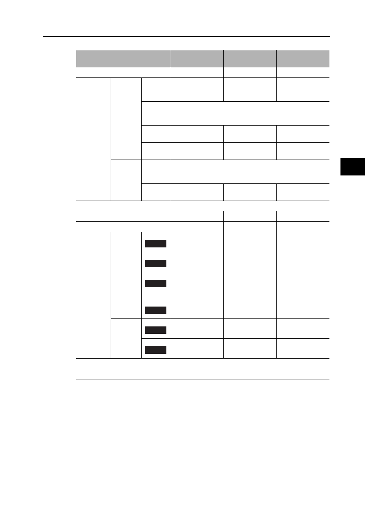
3-1 Servo Drive Specifications
Item
Continuous output current (rms) 13.4 A 18.7 A 33.0 A
Input power
supply
PWM frequency 6.0 kHz
Weight Approx. 2.7 kg Approx. 4.8 kg Approx. 4.8 kg
Maximum applicable motor capacity 2 kW 3 kW 5 kW
Main
circuit
Control
circuit
Power
supply
capacity
Power
supply
voltage
Rated
current
Heat
*1
value
Power
supply
voltage
Heat
*1
value
R88D-KN20H-
ECT-R
3.3 KVA 4.5 KVA 7.5 KVA
3-phase 200 to 230 VAC (170 to 253 V) 50/60 Hz
11.8 A 15.1 A 21.6 A
139 W 108 W 328 W
Single-phase 200 to 230 VAC (170 to 253 V) 50/60 Hz
10 W 10 W 10 W
R88D-KN30H-
ECT-R
R88D-KN50H-
ECT-R
3
Specifications
Applicable
Servomotor
3,000-r/
min
2,000-r/
min
INC
ABS
INC
K2K030H K3K030H
K2K030T K3K030T
K2K020H K3K020H
K2K020T K3K020T
ABS
1,000-r/
min
INC
ABS
Control method All-digital servo
Inverter method IGBT-driven PWM
*1. The heat value is given for rated operation.
− K2K010H K3K010H
− K2K010T
K4K030H
K5K030H
K4K030T
K5K030T
K4K020H
K5K020H
K4K020T
K5K020T
K3K010T
K4K510T
OMNUC G5-series AC Servomotors and Servo Drives User’s Manual (with Built-in EtherCAT Communications)
3-4
Page 94
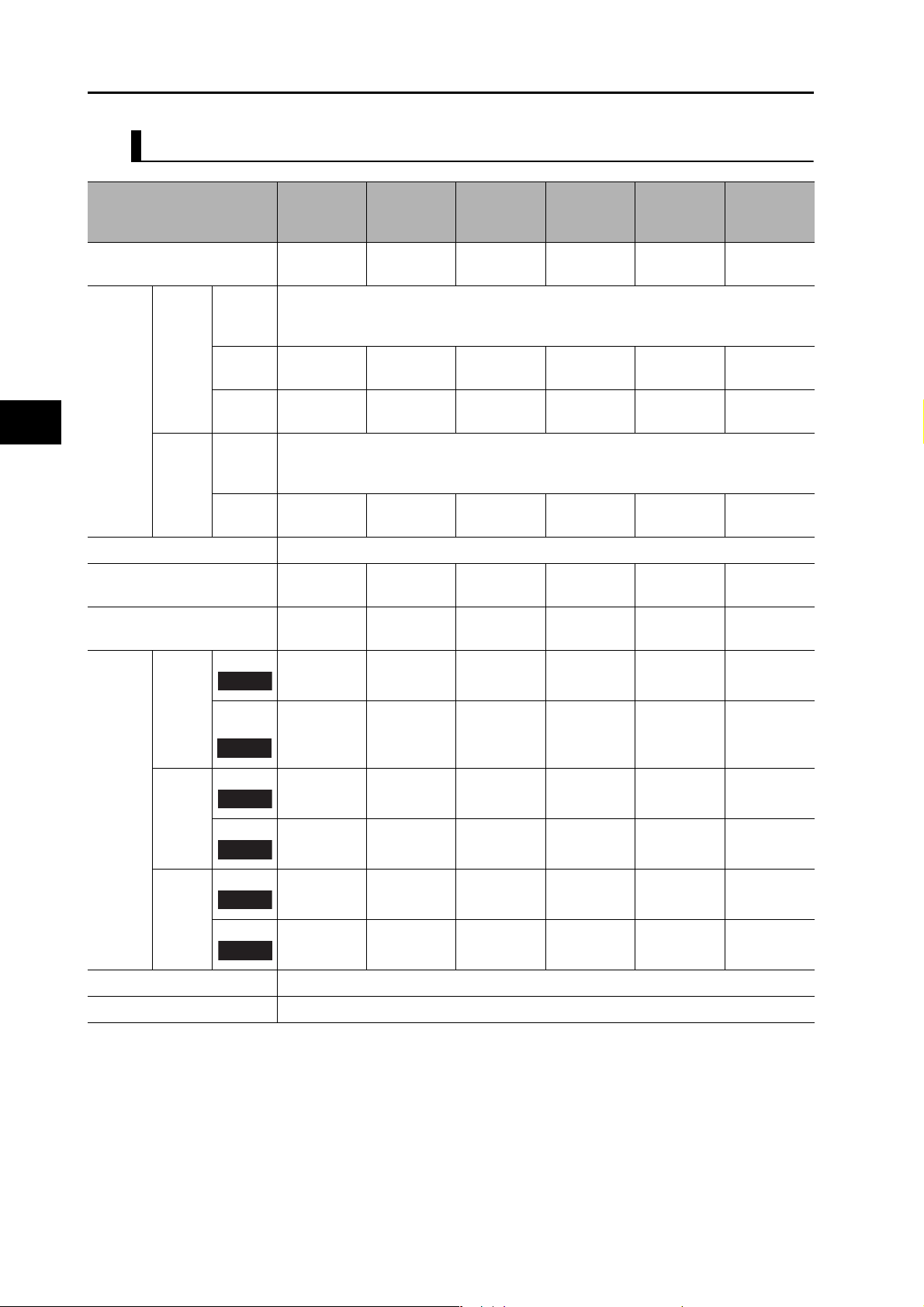
3-1 Servo Drive Specifications
400-VAC Input Models
Continuous output current
(rms)
Input
power
supply
3
PWM frequency 6.0 kHz
Weight Approx. 1.9 kgApprox. 1.9 kgApprox. 1.9 kgApprox. 2.7 kgApprox. 4.7 kgApprox. 4.7
Specifications
Maximum applicable motor
capacity
Applicable Servomotor
Item
Main
circuit
Control
circuit
3,000r/min
Power
supply
voltage
Rated
current
Heat
value
Power
supply
voltage
Heat
value
INC
R88D-
KN06F-
ECT-R
1.5 A 2.9 A 4.7 A 6.7 A 9.4 A 16.5 A
2.1 A 2.8 A 3.9 A 5.9 A 7.6 A 12.1 A
*1
*1
32.2 W 48 W 49 W 65 W 108 W 200 W
9.6 W 9.6 W 9.6 W 12 W 12 W 12 W
600 W 1 kW 1.5 kW 2 kW 3 kW 5 kW
-
R88D-
KN10F-
ECT-R
3-phase 380 to 480 VAC (323 to 528 V) 50/60 Hz
K75030F
R88D-
KN15F-
ECT-R
24 VDC (20.4 to 27.6 V)
K1K030F
K1K530F
R88D-
KN20F-
ECT-R
K2K030F K3K030F
R88D-
KN30F-
ECT-R
R88D-
KN50F-
ECT-R
kg
K4K030F
K5K030F
-
K75030C
ABS
2,000r/min
INC
ABS
1,000r/min
INC
ABS
Control method All-digital servo
Inverter method IGBT-driven PWM
*1. The heat value is given for rated operation.
K40020F
K60020F
K40020C
K60020C
--
--
K1K020F K1K520F K2K020F K3K020F
K1K020C K1K520C K2K020C K3K020C
K1K030C
K1K530C
K90010F
K90010C
K2K030C K3K030C
K4K030C
K5K030C
K4K020F
K5K020F
K4K020C
K5K020C
-
-
K2K010F K3K010F
K2K010C K4K510C
3-5
OMNUC G5-series AC Servomotors and Servo Drives User’s Manual (with Built-in EtherCAT Communications)
Page 95

EtherCAT Communications Specifications
Item Specification
Communications standard IEC 61158 Type 12, IEC 61800-7 CiA 402 Drive Profile
Physical layer 100BASE-TX (IEEE802.3)
Connectors RJ45 × 2 (shielded)
ECAT IN: EtherCAT input
ECAT OUT: EtherCAT output
Communications media Category 5 or higher (cable with double, aluminum tape and braided
shielding) is recommended.
Communications distance Distance between nodes: 100 m max.
Process data Fixed PDO mapping
Mailbox (CoE) Emergency messages, SDO requests, SDO responses, and SDO
information
3-1 Servo Drive Specifications
3
Specifications
Distributed clock Synchronization in DC mode.
DC cycle: 250 µs, 500 µs, 1 ms, 2 ms, 4 ms
LED indicators L/A IN (Link/Activity IN) × 1
L/A OUT (Link/Activity OUT) × 1
RUN × 1
ERR × 1
CiA402 Drive Profile
Cyclic synchronous position mode
Touch probe function (Latch function)
Torque limit function
OMNUC G5-series AC Servomotors and Servo Drives User’s Manual (with Built-in EtherCAT Communications)
3-6
Page 96
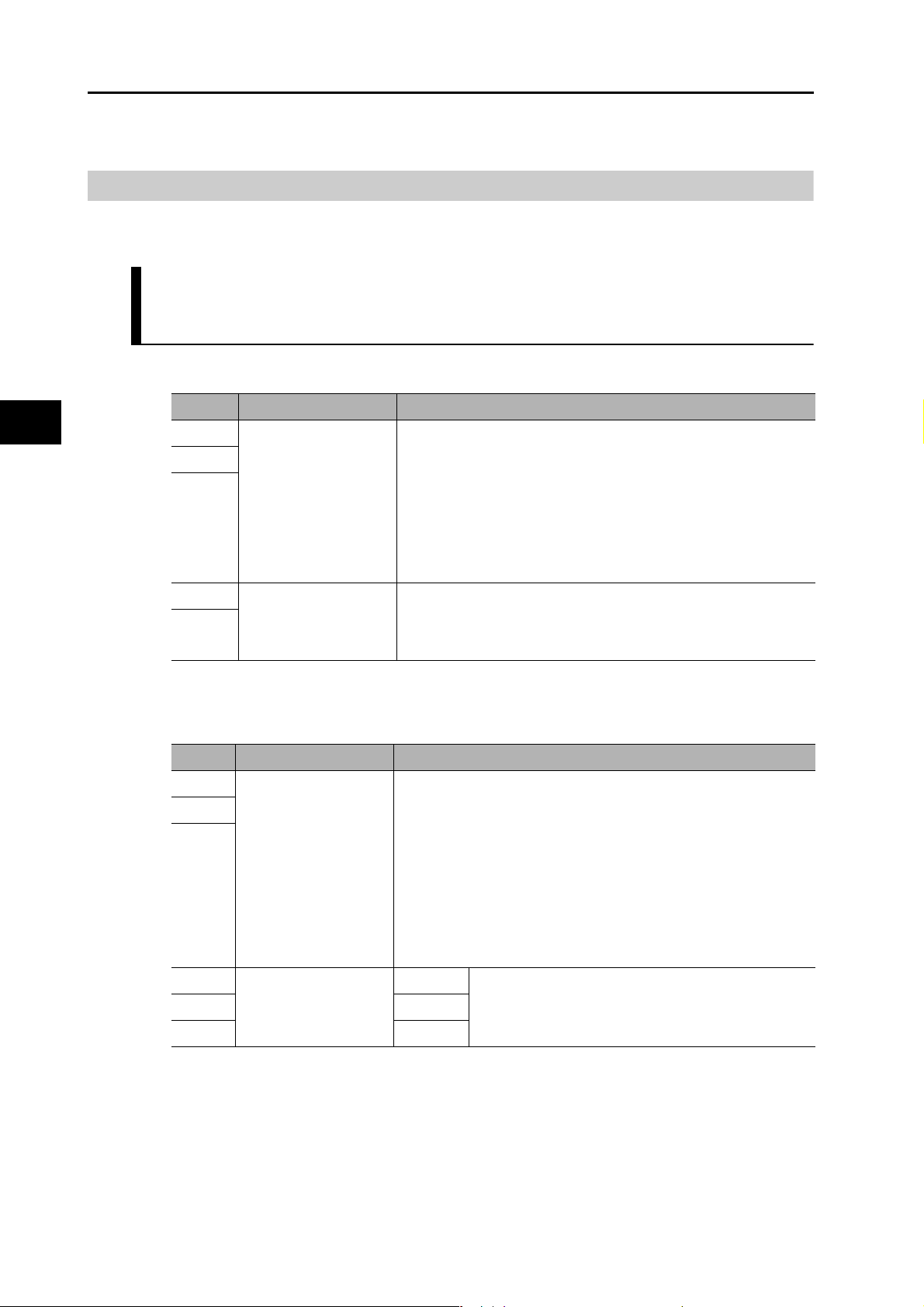
3
3-1 Servo Drive Specifications
Main Circuit and Motor Connections
When wiring the main circuit, use proper wire sizes, grounding systems, and noise resistance.
R88D-KNA5L-ECT-R/-KN01L-ECT-R/-KN02L-ECT-R/-KN04L-ECT-R/
-KN01H-ECT-R/-KN02H-ECT-R/-KN04H-ECT-R/-KN08H-ECT-R/
-KN10H-ECT-R/-KN15H-ECT-R
Main Circuit Connector Specifications (CNA)
Symbol Name Function
L1 Main circuit power
L2
L3
supply input
R88D-KN@L-ECT-R
50 to 400 W: Single-phase 100 to 120 VAC (85 to 132 V) 50/60 Hz
200 to 400 W: 3-phase: 200 to 240 VAC (170 to 264 V) 50/60 Hz
R88D-KN@H-ECT-R
50 W to 1.5 kW: Single-phase: 200 to 240 VAC (170 to 264 V) 50/
60 Hz
100 W to 1.5 kW: 3-phase: 200 to 240 VAC (170 to 264 V) 50/60 Hz
Specifications
Motor Connector Specifications (CNB)
Note: Single-phase should connect to L1 and L3.
L1C Control circuit power
supply input
L2C
Symbol Name Function
B1 External Regeneration
B2
B3
Resistor connection
terminals
U Motor connection
terminals
V Phase V
W Phase W
R88D-KN@L-ECT-R : Single-phase 100 to 120 VAC (85 to 132 V)
50/60 Hz
R88D-KN@H-ECT-R : Single-phase 200 to 240 VAC (170 to 264
V) 50/60 Hz
R88D-KNA5L-ECT-R/-KN01L-ECT-R/-KN02L-ECT-R/-KN01HECT-R/-KN02H-ECT-R/-KN04H-ECT-R:
Normally, do not short B1 and B2. Doing so may result in
malfunctioning. If there is high regenerative energy, connect an
External Regeneration Resistor between B1 and B2.
R88D-KN04L-ECT-R/-KN08H-ECT-R/-KN10H-ECT-R/-KN15HECT-R:
Normally B2 and B3 are shorted. Do not short B1 and B2. Doing so
may result in malfunctioning. If there is high regenerative energy,
remove the short bar between B2 and B3 and connect an External
Regeneration Resistor between B1 and B2.
Phase U These are the output terminals to the Servomotor.
Be sure to wire them correctly.
3-7
OMNUC G5-series AC Servomotors and Servo Drives User’s Manual (with Built-in EtherCAT Communications)
Page 97

R88D-KN20H-ECT-R
Main Circuit Connector Specifications (CNA)
Symbol Name Function
3-1 Servo Drive Specifications
L1 Main circuit power
L2
L3
L1C Control circuit power
L2C
supply input
supply input
R88D-KN@H-ECT-R (2 kW) :
3-phase: 200 to 230 VAC (170 to 253 V) 50/60 Hz
R88D-KN@H-ECT-R : Single-phase 200 to 230 VAC (170 to 253
V) 50/60 Hz
Motor Connector Specifications (CNB)
Symbol Name Function
U Motor connection
V Phase V
W Phase W
terminals
Phase U These are the output terminals to the Servomotor.
Be sure to wire them correctly.
External Regeneration Resistor Connector Specifications (CNC)
Symbol Name Function
B1 External Regeneration
B2
B3
NC Do not connect.
Resistor connection
terminals
Normally B2 and B3 are connected.
If there is high regenerative energy, remove the short-circuit bar
between B2 and B3 and connect an External Regeneration
Resistor between B1 and B2.
3
Specifications
Precautions for Correct Use
Tighten the ground screws to the torque of 0.7 to 0.8 N•m (M4) or 1.4 to 1.6 N•m (M5).
OMNUC G5-series AC Servomotors and Servo Drives User’s Manual (with Built-in EtherCAT Communications)
3-8
Page 98

3-1 Servo Drive Specifications
R88D-KN30H-ECT-R/R88D-KN50H-ECT-R
Main Circuit Terminal Block Specifications
Symbol Name Function
3
Specifications
L1 Main circuit power
L2
L3
L1C Control circuit power
L2C
B1 External Regeneration
B2
B3
NC Do not connect.
U Motor connection
V Phase V
W Phase W
supply input
supply input
Resistor connection
terminals
terminals
R88D-KN@H-ECT-R (3 to 5 kW):
3-phase 200 to 230 VAC (170 to 253 V) 50/60 Hz
R88D-KN@H-ECT-R : Single-phase 200 to 230 VAC (170 to 253
V) 50/60 Hz
Normally B2 and B3 are connected.
If there is high regenerative energy, remove the short-circuit bar
between B2 and B3 and connect an External Regeneration
Resistor between B1 and B2.
Phase U These are the output terminals to the Servomotor.
Be sure to wire them correctly.
Precautions for Correct Use
Tighten the terminal block screws to the torque of 0.75 N•m (M4) or 1.5 N•m (M5).
If the torque for terminal block screws exceeds 1.2 N•m (M4) or 2.0 N•m (M5), the terminal block
may be damaged.
Tighten the fixing screw of the terminal block cover to the torque of 0.2 N•m (M3).
Tighten the ground screws to the torque of 0.7 to 0.8 N•m (M4) or 1.4 to 1.6 N•m (M5).
3-9
OMNUC G5-series AC Servomotors and Servo Drives User’s Manual (with Built-in EtherCAT Communications)
Page 99

3-1 Servo Drive Specifications
R88D-KN06F-ECT-R/-KN10F-ECT-R/-KN15F-ECT-R/-KN20F-ECT-R
Main Circuit Connector Specifications (CNA)
Symbol Name Function
L1 Main circuit power supply
L2
L3
input
R88D-KN@F-ECT-R
600 W to 1.5 kW: 3-phase: 380 to 480 VAC (323 to 528 V)
50/60 Hz
Motor Connector Specifications (CNB)
Symbol Name Function
U Motor connection
terminals
V Phase V
WPhase W
Phase U These are the output terminals to the Servomotor.
Be sure to wire them correctly.
Control Circuit Connector Specifications (CNC)
Symbol Name Function
24 V Control circuit power
0 V
supply input
24 VDC ± 15%
3
Specifications
External Regeneration Resistor Connector Specifications (CND)
Symbol Name Function
B1 External Regeneration
B2
B3
NC Do not connect.
Resistor connection
terminals
Normally B2 and B3 are connected.
If there is high regenerative energy, remove the short-circuit bar
between B2 and B3 and connect an External Regeneration
Resistor between B1 and B2.
OMNUC G5-series AC Servomotors and Servo Drives User’s Manual (with Built-in EtherCAT Communications)
3-10
Page 100

3-1 Servo Drive Specifications
R88D-KN30F-ECT-R/R88D-KN50F-ECT-R
Main Circuit Terminal Block Specifications (TB1)
Symbol Name Function
3
Specifications
24 V Control circuit power
0 V
supply input
24 VDC ± 15%
Main Circuit Terminal Block Specifications (TB2)
Symbol Name Function
L1 Main circuit power supply
L2
L3
B1 External Regeneration
B2
B3
NC Do not connect.
U Motor connection
V Phase V
W Phase W
input
Resistor connection
terminals
terminals
R88D-KN@F-ECT-R (3 to 5 kW):
3-phase 380 to 480 VAC (323 to 528 V) 50/60 Hz
Normally B2 and B3 are connected.
If there is high regenerative energy, remove the short-circuit bar
between B2 and B3 and connect an External Regeneration
Resistor between B1 and B2.
Phase U These are the output terminals to the Servomotor.
Be sure to wire them correctly.
Precautions for Correct Use
Tighten the terminal block screws to the torque of 0.75 N•m (M4) or 1.5 N•m (M5).
If the torque for terminal block screws exceeds 1.2 N•m (M4) or 2.0 N•m (M5), the terminal block
may be damaged.
Tighten the fixing screw of the terminal block cover to the torque of 0.2 N•m (M3).
Tighten the ground screws to the torque of 0.7 to 0.8 N•m (M4) or 1.4 to 1.6 N•m (M5).
3-11
OMNUC G5-series AC Servomotors and Servo Drives User’s Manual (with Built-in EtherCAT Communications)
 Loading...