

Page 1

Cat. No. I533-E1-04
SMARTSTEP A SERIES
R7M-A@ (Servomotors)
R7D-AP@ (Servo Drivers)
Servomotors/Servo Drivers
USER’S MANUAL
Page 2

Thank you for choosing this SMARTSTEP A-series product. Proper use and handling
of the product will ensure proper product performance, will lengthen product life, and
may prevent possible accidents.
Please read this manual thoroughly and handle and operate the product with care.
Please keep this manual handy for reference after reading it.
1.To ensure safe and proper use of the OMRON Inverters, please read this USER'S MANUAL (Cat. No.
I533-E1) to gain sufficient knowledge of the devices, safety information, and precautions before actual
use.
2.The products are illustrated without covers and shieldings for closer look in this USER'S MANUAL. For
actual use of the products, make sure to use the covers and shieldings as specified.
3.This USER'S MANUAL and other related user's manuals are to be delivered to the actual end users of the
products.
4.Please keep this manual close at hand for future reference.
5.If the product has been left unused for a long time, please inquire at our sales representative.
NOTICE
1.This manual describes information about installation, wiring, switch setting, and troubleshooting of the
SMARTSTEP A-series Servomotors and Servo Drivers. For information about actual operating procedures using a Parameter Unit, refer to the SMARTSTEP A Series Operation Manual (I534).
2.Be sure that this manual accompanies the product to its final user.
3.Although care has been given in documenting the product, please contact your OMRON representative
if you have any suggestions on improving this manual.
4.Assume that anything not specifically described in this manual is not possible.
5.Do not allow the Servomotor or Servo Driver to be wired, set, or operated (from a Parameter Unit) by
anyone that is not a profession electrical engineer or the equivalent.
6.We recommend that you add the following precautions to any instruction manuals you prepare for the
system into which the product is being installed.
• Precautions on the dangers of high-voltage equipment.
• Precautions on touching the terminals of the product even after power has been turned OFF. (These
terminals are live even with the power turned OFF.)
7.Specifications and functions may be changed without notice in order to improve product performance.
8.Positive and negative rotation of AC Servomotors described in this manual are defined as looking at the
end of the output shaft of the motor as follows: Counterclockwise rotation is positive and clockwise rotation is negative.
9.Do not perform withstand-voltage or other megameter tests on the product. Doing so may damage internal components.
10.Servomotors and Servo Drivers have a finite service life. Be sure to keep replacement products on hand
and to consider the operating environment and other conditions affecting the service life.
11.Do not set values for any parameters not described in this manual. Operating errors may result. Consult
your OMRON representative if you have questions.
12.Before using the product under conditions which are not described in the manual or applying the product
to nuclear control systems, railroad systems, aviation systems, vehicles, combustion systems, medical
equipment, amusement machines, safety equipment, and other systems, machines, and equipment that
may have a serious influence on lives and property if used improperly, consult your OMRON representative.
Items to Check Before Unpacking
1.Check the following items before removing the product from the package:
• Has the correct product been delivered (i.e., the correct model number and specifications)?
• Has the product been damaged in shipping?
2.Check that the following accessories have been delivered.
• Safety Precautions
No connectors or mounting screws are provided. Obtain these separately.
Page 3

USER’S MANUAL
SMARTSTEP A SERIES
MODELS R7M-A@ (Servomotors)
R7D-AP@ (Servo Drivers)
Servomotors/Servo Drivers
Page 4

Page 5

Notice:
r
f
OMRON products are manufactured for use according to proper procedures by a qualified operator
and only for the purposes described in this manual.
The following conventions are used to indicate and classify precautions in this manual. Always heed
the information provided with them. Failure to heed precautions can result in injury to people or damage to property.
!DANGER Indicates an imminently hazardous situation which, if not avoided, will result in
death or serious injury. Additionally, there may be severe property damage.
!WARNING Indicates a potentially hazardous situation which, if not avoided, could result in
death or serious injury. Additionally, there may be severe property damage.
!Caution Indicates a potentially hazardous situation which, if not avoided, may result in
minor or moderate injury, or property damage.
OMRON Product References
All OMRON products are capitalized in this manual. The word “Unit” is also capitalized when it refers to
an OMRON product, regardless of whether or not it appears in the proper name of the product.
The abbreviation “Ch,” which appears in some displays and on some OMRON products, often means
“word” and is abbreviated “Wd” in documentation in this sense.
The abbreviation “PC” means Programmable Controller and is not used as an abbreviation for anything
else.
Visual Aids
The following headings appear in the left column of the manual to help you locate different types of
information.
Note Indicates information of particular interest for efficient and convenient operation of the product.
OMRON, 2001
All rights reserved. No part of this publication may be reproduced, stored in a retrieval system, or transmitted, in any form, o
by any means, mechanical, electronic, photocopying, recording, or otherwise, without the prior written permission o
OMRON.
No patent liability is assumed with respect to the use of the information contained herein. Moreover, because OMRON is constantly striving to improve its high-quality products, the information contained in this manual is subject to change without
notice. Every precaution has been taken in the preparation of this manual. Nevertheless, OMRON assumes no responsibility
for errors or omissions. Neither is any liability assumed for damages resulting from the use of the information contained in
this publication.
Page 6

Page 7

General Warnings
Observe the following warnings when using the SMARTSTEP Servomotor and Servo Driver and all
connected or peripheral devices.
This manual may include illustrations of the product with protective covers removed in order to
describe the components of the product in detail. Make sure that these protective covers are on the
product before use.
Consult your OMRON representative when using the product after a long period of storage.
!WARNING Always connect the frame ground terminals of the Servo Driver and the Servomo-
tor to a class-3 ground (to 100
result in electric shock.
!WARNING Do not touch the inside of the Servo Driver. Doing so may result in electric shock.
!WARNING Do not remove the front cover, terminal covers, cables, or optional items while the
power is being supplied. Doing so may result in electric shock.
!WARNING Installation, operation, maintenance, or inspection must be performed by autho-
rized personnel. Not doing so may result in electric shock or injury.
Ω or less). Not connecting to a class-3 ground may
!WARNING Wiring or inspection must not be performed for at least five minutes after turning
OFF the power supply. Doing so may result in electric shock.
!WARNING Do not damage, press, or put excessive stress or heavy objects on the cables.
Doing so may result in electric shock.
!WARNING Do not touch the rotating parts of the Servomotor in operation. Doing so may
result in injury.
!WARNING Do not modify the product. Doing so may result in injury or damage to the product.
!WARNING Provide a stopping mechanism on the machine to ensure safety. The holding
brake is not designed as a stopping mechanism for safety purposes.
!WARNING Provide an external emergency stopping mechanism that can stop operation and
shutting off the power supply immediately. Not doing so may result in injury.
!WARNING Do not come close to the machine immediately after resetting momentary power
interruption to avoid an unexpected restart. (Take appropriate measures to secure
safety against an unexpected restart.) Doing so may result in injury.
!Caution Use the Servomotors and Servo Drivers in a specified combination. Using them
incorrectly may result in fire or damage to the products.
Page 8

!Caution Do not store or install the product in the following places. Doing so may result in
fire, electric shock, or damage to the product.
• Locations subject to direct sunlight.
• Locations subject to temperatures or humidity outside the range specified in the
specifications.
• Locations subject to condensation as the result of severe changes in temperature.
• Locations subject to corrosive or flammable gases.
• Locations subject to dust (especially iron dust) or salts.
• Locations subject to shock or vibration.
• Locations subject to exposure to water, oil, or chemicals.
!Caution Do not touch the Servo Driver radiator, Servo Driver regeneration resistor, or Ser-
vomotor while the power is being supplied or soon after the power is turned OFF.
Doing so may result in a skin burn due to the hot surface.
Storage and Transportation Precautions
!Caution Do not hold the product by the cables or motor shaft while transporting it. Doing so
may result in injury or malfunction.
!Caution Do not place any load exceeding the figure indicated on the product. Doing so
may result in injury or malfunction.
Installation and Wiring Precautions
!Caution Do not step on or place a heavy object on the product. Doing so may result in
injury.
!Caution Do not cover the inlet or outlet ports and prevent any foreign objects from entering
the product. Doing so may result in fire.
!Caution Be sure to install the product in the correct direction. Not doing so may result in
malfunction.
!Caution Provide the specified clearances between the Servo Driver and the control panel
or with other devices. Not doing so may result in fire or malfunction.
!Caution Do not apply any strong impact. Doing so may result in malfunction.
!Caution Be sure to wire correctly and securely. Not doing so may result in motor runaway,
injury, or malfunction.
Page 9

!Caution Be sure that all the mounting screws, terminal screws, and cable connector
screws are tightened to the torque specified in the relevant manuals. Incorrect
tightening torque may result in malfunction.
!Caution Use crimp terminals for wiring. Do not connect bare stranded wires directly to ter-
minals. Connection of bare stranded wires may result in burning.
!Caution Always use the power supply voltage specified in the User’s Manual. An incorrect
voltage may result in malfunction or burning.
!Caution Take appropriate measures to ensure that the specified power with the rated volt-
age and frequency is supplied. Be particularly careful in places where the power
supply is unstable. An incorrect power supply may result in malfunction.
!Caution Install external breakers and take other safety measures against short-circuiting in
external wiring. Insufficient safety measures against short-circuiting may result in
burning.
!Caution Take appropriate and sufficient countermeasures when installing systems in the
following locations. Failure to do so may result in damage to the product.
• Locations subject to static electricity or other forms of noise.
• Locations subject to strong electromagnetic fields and magnetic fields.
• Locations subject to possible exposure to radioactivity.
• Locations close to power supplies.
Operation and Adjustment Precautions
!Caution Confirm that no adverse effects will occur in the system before performing the test
operation. Not doing so may result in equipment damage.
!Caution Check the newly set parameters and switches for proper execution before actually
running them. Not doing so may result in equipment damage.
!Caution Do not make any extreme adjustments or setting changes. Doing so may result in
unstable operation and injury.
!Caution Separate the Servomotor from the machine, check for proper operation, and then
connect to the machine. Not doing so may cause injury.
!Caution When an alarm occurs, remove the cause, reset the alarm after confirming safety,
and then resume operation. Not doing so may result in injury.
!Caution Do not use the built-in brake of the Servomotor for ordinary braking. Doing so may
result in malfunction.
Page 10

Maintenance and Inspection Precautions
!WARNING Do not attempt to disassemble, repair, or modify any Units. Any attempt to do so
may result in malfunction, fire, or electric shock.
!Caution Resume operation only after transferring to the new Unit the contents of the data
required for operation. Not doing so may result in an unexpected operation.
Page 11
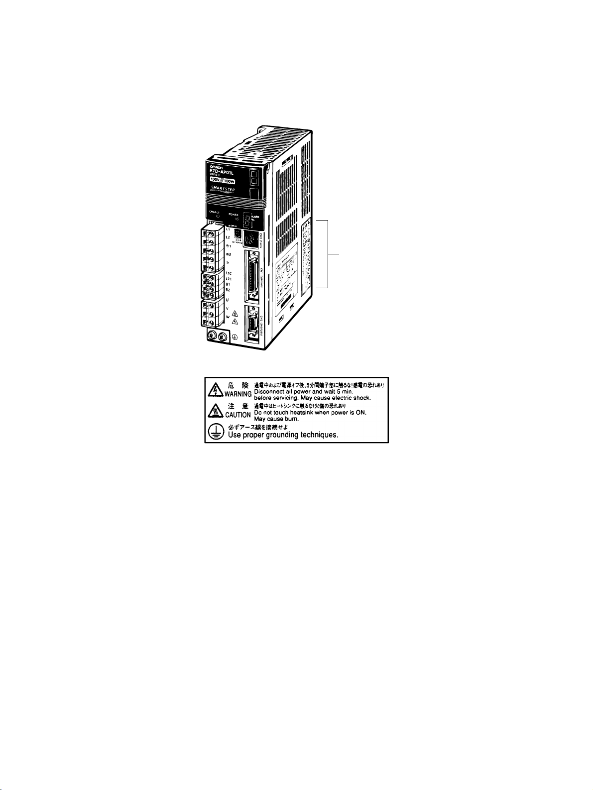
Warning Labels
Warning labels are pasted on the product as shown in the following illustration. Be sure to follow the
instructions given there.
Warning label
Example from R7D-AP01L
Example from R7D-AP01L
Page 12

Page 13

Read and Understand this Manual
Please read and understand this manual before using the product. Please consult your OMRON
representative if you have any questions or comments.
Warranty and Limitations of Liability
WARRANTY
OMRON's exclusive warranty is that the products are free from defects in materials and workmanship for a
period of one year (or other period if specified) from date of sale by OMRON.
OMRON MAKES NO WARRANTY OR REPRESENTATION, EXPRESS OR IMPLIED, REGARDING NONINFRINGEMENT, MERCHANTABILITY, OR FITNESS FOR PARTICULAR PURPOSE OF THE
PRODUCTS. ANY BUYER OR USER ACKNOWLEDGES THAT THE BUYER OR USER ALONE HAS
DETERMINED THAT THE PRODUCTS WILL SUITABLY MEET THE REQUIREMENTS OF THEIR
INTENDED USE. OMRON DISCLAIMS ALL OTHER WARRANTIES, EXPRESS OR IMPLIED.
LIMITATIONS OF LIABILITY
OMRON SHALL NOT BE RESPONSIBLE FOR SPECIAL, INDIRECT, OR CONSEQUENTIAL DAMAGES,
LOSS OF PROFITS OR COMMERCIAL LOSS IN ANY WAY CONNECTED WITH THE PRODUCTS,
WHETHER SUCH CLAIM IS BASED ON CONTRACT, WARRANTY, NEGLIGENCE, OR STRICT
LIABILITY.
In no event shall the responsibility of OMRON for any act exceed the individual price of the product on which
liability is asserted.
IN NO EVENT SHALL OMRON BE RESPONSIBLE FOR WARRANTY, REPAIR, OR OTHER CLAIMS
REGARDING THE PRODUCTS UNLESS OMRON'S ANALYSIS CONFIRMS THAT THE PRODUCTS
WERE PROPERLY HANDLED, STORED, INSTALLED, AND MAINTAINED AND NOT SUBJECT TO
CONTAMINATION, ABUSE, MISUSE, OR INAPPROPRIATE MODIFICATION OR REPAIR.
Page 14

Application Considerations
SUITABILITY FOR USE
OMRON shall not be responsible for conformity with any standards, codes, or regulations that apply to the
combination of products in the customer's application or use of the products.
At the customer's request, OMRON will provide applicable third party certification documents identifying
ratings and limitations of use that apply to the products. This information by itself is not sufficient for a
complete determination of the suitability of the products in combination with the end product, machine,
system, or other application or use.
The following are some examples of applications for which particular attention must be given. This is not
intended to be an exhaustive list of all possible uses of the products, nor is it intended to imply that the uses
listed may be suitable for the products:
• Outdoor use, uses involving potential chemical contamination or electrical interference, or conditions or
uses not described in this manual.
• Nuclear energy control systems, combustion systems, railroad systems, aviation systems, medical
equipment, amusement machines, vehicles, safety equipment, and installations subject to separate
industry or government regulations.
• Systems, machines, and equipment that could present a risk to life or property.
Please know and observe all prohibitions of use applicable to the products.
NEVER USE THE PRODUCTS FOR AN APPLICATION INVOLVING SERIOUS RISK TO LIFE OR
PROPERTY WITHOUT ENSURING THAT THE SYSTEM AS A WHOLE HAS BEEN DESIGNED TO
ADDRESS THE RISKS, AND THAT THE OMRON PRODUCTS ARE PROPERLY RATED AND
INSTALLED FOR THE INTENDED USE WITHIN THE OVERALL EQUIPMENT OR SYSTEM.
PROGRAMMABLE PRODUCTS
OMRON shall not be responsible for the user's programming of a programmable product, or any
consequence thereof.
Page 15

Disclaimers
CHANGE IN SPECIFICATIONS
Product specifications and accessories may be changed at any time based on improvements and other
reasons.
It is our practice to change model numbers when published ratings or features are changed, or when
significant construction changes are made. However, some specifications of the products may be changed
without any notice. When in doubt, special model numbers may be assigned to fix or establish key
specifications for your application on your request. Please consult with your OMRON representative at any
time to confirm actual specifications of purchased products.
DIMENSIONS AND WEIGHTS
Dimensions and weights are nominal and are not to be used for manufacturing purposes, even when
tolerances are shown.
PERFORMANCE DATA
Performance data given in this manual is provided as a guide for the user in determining suitability and does
not constitute a warranty. It may represent the result of OMRON's test conditions, and the users must
correlate it to actual application requirements. Actual performance is subject to the OMRON Warranty and
Limitations of Liability.
ERRORS AND OMISSIONS
The information in this manual has been carefully checked and is believed to be accurate; however, no
responsibility is assumed for clerical, typographical, or proofreading errors, or omissions.
Page 16

Page 17

Table of Contents
Chapter 1. Introduction. . . . . . . . . . . . . . . . . . . . . . . . . . . . . . . . . . . . 1-1
1-1 Features. . . . . . . . . . . . . . . . . . . . . . . . . . . . . . . . . . . . . . . . . . . . . . . . . . . . . . . . . . . . . . . . . . 1-2
1-2 System Configuration. . . . . . . . . . . . . . . . . . . . . . . . . . . . . . . . . . . . . . . . . . . . . . . . . . . . . . . 1-4
1-3 Servo Driver Nomenclature . . . . . . . . . . . . . . . . . . . . . . . . . . . . . . . . . . . . . . . . . . . . . . . . . .1-5
1-4 Applicable Standards . . . . . . . . . . . . . . . . . . . . . . . . . . . . . . . . . . . . . . . . . . . . . . . . . . . . . . . 1-6
1-5 System Block Diagrams . . . . . . . . . . . . . . . . . . . . . . . . . . . . . . . . . . . . . . . . . . . . . . . . . . . . .1-7
Chapter 2. Standard Models and Specifications. . . . . . . . . . . . . . . . 2-1
2-1 Standard Models. . . . . . . . . . . . . . . . . . . . . . . . . . . . . . . . . . . . . . . . . . . . . . . . . . . . . . . . . . . 2-2
2-2 External and Mounted Dimensions . . . . . . . . . . . . . . . . . . . . . . . . . . . . . . . . . . . . . . . . . . . . 2-6
2-3 Servo Driver Specifications . . . . . . . . . . . . . . . . . . . . . . . . . . . . . . . . . . . . . . . . . . . . . . . . . . 2-17
2-4 Servomotor Specifications . . . . . . . . . . . . . . . . . . . . . . . . . . . . . . . . . . . . . . . . . . . . . . . . . . . 2-31
2-5 Reduction Gear Specifications . . . . . . . . . . . . . . . . . . . . . . . . . . . . . . . . . . . . . . . . . . . . . . . . 2-39
2-6 Cable and Connector Specifications. . . . . . . . . . . . . . . . . . . . . . . . . . . . . . . . . . . . . . . . . . . . 2-43
2-7 Servo Relay Units and Cable Specifications . . . . . . . . . . . . . . . . . . . . . . . . . . . . . . . . . . . . . 2-58
2-8 Parameter Unit Specifications . . . . . . . . . . . . . . . . . . . . . . . . . . . . . . . . . . . . . . . . . . . . . . . .2-111
2-9 External Regeneration Resistor Specifications. . . . . . . . . . . . . . . . . . . . . . . . . . . . . . . . . . . . 2-113
2-10 DC Reactors . . . . . . . . . . . . . . . . . . . . . . . . . . . . . . . . . . . . . . . . . . . . . . . . . . . . . . . . . . . . . . 2-114
Chapter 3. System Design and Installation . . . . . . . . . . . . . . . . . . . . 3-1
3-1 Installation Conditions . . . . . . . . . . . . . . . . . . . . . . . . . . . . . . . . . . . . . . . . . . . . . . . . . . . . . . 3-3
3-2 Wiring. . . . . . . . . . . . . . . . . . . . . . . . . . . . . . . . . . . . . . . . . . . . . . . . . . . . . . . . . . . . . . . . . . . 3-8
3-3 Regenerative Energy Absorption . . . . . . . . . . . . . . . . . . . . . . . . . . . . . . . . . . . . . . . . . . . . . . 3-37
Chapter 4. Operation. . . . . . . . . . . . . . . . . . . . . . . . . . . . . . . . . . . . . . 4-1
4-1 Operational Procedure . . . . . . . . . . . . . . . . . . . . . . . . . . . . . . . . . . . . . . . . . . . . . . . . . . . . . . 4-3
4-2 Switch Settings . . . . . . . . . . . . . . . . . . . . . . . . . . . . . . . . . . . . . . . . . . . . . . . . . . . . . . . . . . . . 4-4
4-3 Preparing for Operation . . . . . . . . . . . . . . . . . . . . . . . . . . . . . . . . . . . . . . . . . . . . . . . . . . . . . 4-7
4-4 Trial Operation . . . . . . . . . . . . . . . . . . . . . . . . . . . . . . . . . . . . . . . . . . . . . . . . . . . . . . . . . . . . 4-9
4-5 Gain Adjustments . . . . . . . . . . . . . . . . . . . . . . . . . . . . . . . . . . . . . . . . . . . . . . . . . . . . . . . . . . 4-11
4-6 User Parameters . . . . . . . . . . . . . . . . . . . . . . . . . . . . . . . . . . . . . . . . . . . . . . . . . . . . . . . . . . . 4-15
4-7 Operating Functions . . . . . . . . . . . . . . . . . . . . . . . . . . . . . . . . . . . . . . . . . . . . . . . . . . . . . . . . 4-26
Chapter 5. Troubleshooting . . . . . . . . . . . . . . . . . . . . . . . . . . . . . . . . 5-1
5-1 Measures when Trouble Occurs . . . . . . . . . . . . . . . . . . . . . . . . . . . . . . . . . . . . . . . . . . . . . . . 5-2
5-2 Alarms . . . . . . . . . . . . . . . . . . . . . . . . . . . . . . . . . . . . . . . . . . . . . . . . . . . . . . . . . . . . . . . . . . 5-5
5-3 Troubleshooting . . . . . . . . . . . . . . . . . . . . . . . . . . . . . . . . . . . . . . . . . . . . . . . . . . . . . . . . . . . 5-7
5-4 Overload Characteristics (Electron Thermal Characteristics) . . . . . . . . . . . . . . . . . . . . . . . . 5-15
5-5 Periodic Maintenance . . . . . . . . . . . . . . . . . . . . . . . . . . . . . . . . . . . . . . . . . . . . . . . . . . . . . . . 5-16
Chapter 6. Appendix . . . . . . . . . . . . . . . . . . . . . . . . . . . . . . . . . . . . . . 6-1
6-1 Connection Examples. . . . . . . . . . . . . . . . . . . . . . . . . . . . . . . . . . . . . . . . . . . . . . . . . . . . . . . 6-2
Revision History . . . . . . . . . . . . . . . . . . . . . . . . . . . . . . . . . . . . . . . . . . R-1
Page 18

Page 19

Introduction
1-1 Features
1-2 System Configuration
1-3 Servo Driver Nomenclature
1-4 Applicable Standards
1-5 System Block Diagrams
Chapter 1
Page 20

Introduction
Chapter 1
1-1 Features
The SMARTSTEP A-series Servomotors and Servo Drivers have been developed as pulse string
input-type Position Controllers to replace stepping motors in simple positioning systems. The
SMARTSTEP A-series Servomotors and Servo Drivers combine the stepping motor’s ease of use
with faster positioning resulting from high speed and high torque, higher reliability with no loss of
positioning accuracy even during sudden load changes, and other advanced features.
■ Faster Response and Rotation Speed
SMARTSTEP A-series Servomotors and Servo Drivers incorporate the same high-speed and hightorque features, unachievable with stepping motors, as the OMNUC W Series. The SMARTSTEP Aseries Servomotors provide faster rotation speeds of up to 4,500 r/min, with constant operation possible at this speed. Faster output torque of up to 1 s can output up to approximately 300% of the
rated torque, providing even faster middle- and long-stroke positioning.
■ Constant Accuracy
The A-series product line’s higher encoder resolution of 2,000 pulses/rotation provides feedback
control enabling continuous operation without loss of positioning accuracy, even with sudden load
changes or sudden acceleration or deceleration.
■ Minimal Setting with Servo Driver Front Panel Switches
The SMARTSTEP A Series can be operated immediately without time-consuming parameter setting.
The A-series Servo Drivers’ front panel switches enable easier alteration of function or positioning
resolution settings.
● Resolution Settings
SMARTSTEP A-series Servomotor resolution can be selected from the following four levels:
500 pulses/rotation (0.72
rotation (0.072
● Command Pulse Input Setting
SMARTSTEP A-series command pulse input setting can be switched between CW/CCW (2-pulse)
and SIGN/PULS (single-pulse) methods to easily adapt to Position Controller output specifications.
● Dynamic Brake Setting
SMARTSTEP A-series Servomotors can be forcibly decelerated to a stop at RUN OFF or when
an alarm occurs.
● Gain Setting
°/step); or 10,000 pulses/rotation (0.036°/step)
°/step); 1,000 pulses/rotation (0.36°/step) (default setting); 5,000 pulses/
A special rotary switch on SMARSTEP A-series Servo Drivers enables easy gain setting. Online
autotuning can also be activated with the flick of a switch, and responsiveness can be easily
matched to the machinery to be used.
1-2
Page 21

Introduction
Note Using a Parameter Unit or personal computer enables operation with parameter settings.
■ Cylinder-style and Flat-style Servomotors
The SMARTSTEP A Series offers Flanged Cylinder-style Servomotors, with a smaller mounting
area, and Flat-style Servomotors, with a shorter overall length. The Flat Servomotor depth dimensions are approximately the same as those of stepping motors of the same output capacity. Servomotors can be selected by size, thereby making equipment more compact.
■ A Wider Selection of Programming Devices
Special SMARTSTEP A-series Parameter Units and personal computer monitoring software are
available. The special monitoring software enables performing parameter setting, speed and current
monitoring, speed and current waveform displays, I/O monitoring, autotuning, jogging, and other
operations from a computer. It is also possible to perform multiple-axis communications that set the
parameters and monitor operations for multiple Servo Drivers. For details, refer to the Servo Driver
Personal Computer Monitor Software (CD-ROM) for Windows 95/98, Version 2.0 (WMON Win
Ver.2.0) (Catalog No.: SBCE-011).
Chapter 1
1-3
Page 22
Introduction
SCROLL
MODE/SET
DATA
JOG
RUN
DRIVER PR
PR DRIVER
READ
WRITE
B.B
INP
VCMP
TGON
REF
POWER
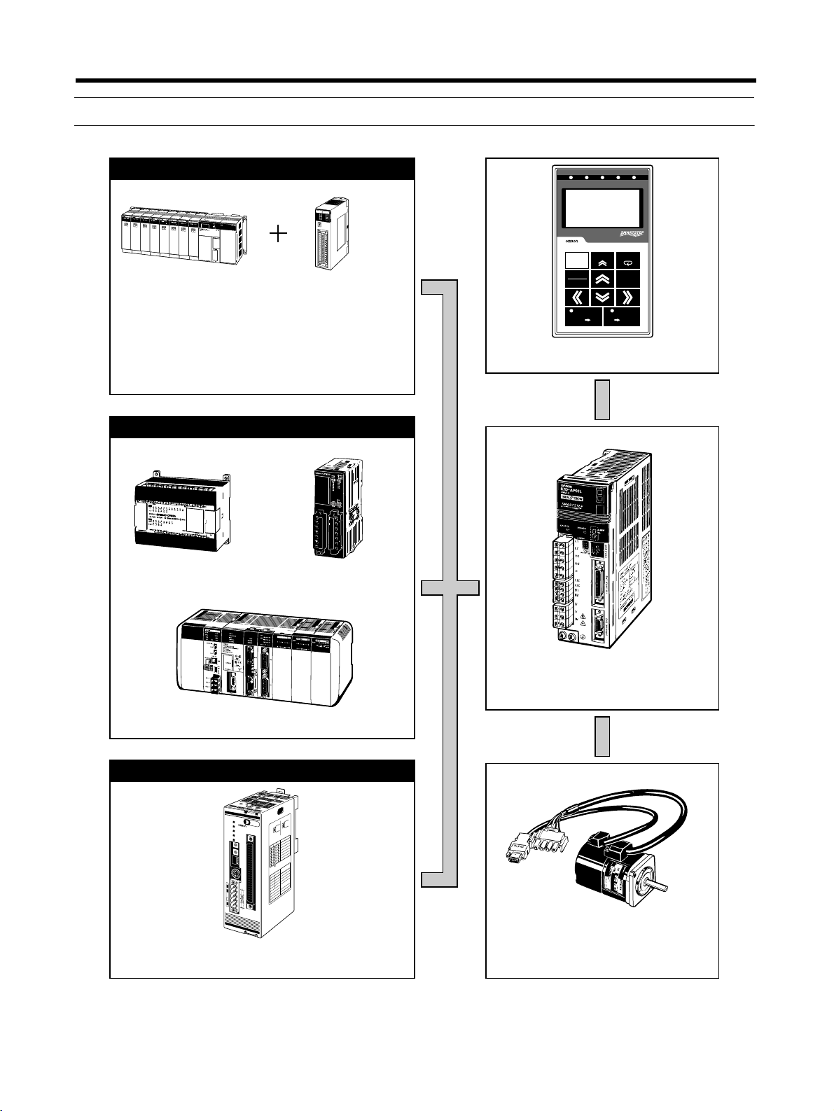
1-2 System Configuration
SYSMAC + Position Control Unit with pulse string output
N
C
4
1
3
R
U
N
X
E
R
R
O
R
Y
S
E
N
S
Z
D
A
T
A
U
M
A
C
H
IN
E
N
o
.
C
N
1
C
N
2
B
2
4
A
2
4
B
1
A
1
SYSMAC CJ/CS/C/CV
Programmable Controller
SYSMAC Programmable Controllers with pulse outputs
Position Control Units
CJ1W-NC113/213/413
CJ1W-NC133/233/433
CS1W-NC113/213/413
CS1W-NC133/233/433
C200HW-NC113/213/413
C500-NC113/211
Pulse String
Chapter 1
B.B
INP
TGON
REF
SCROLL
MODE/SET
DATA
WRITE
PR DRIVER
POWER
VCMP
R7A–PR02A PARAMETER UNIT
RESET
JOG
RUN
READ
DRIVER PR
R7A-PR02A Parameter Unit
(Hand-held)
SYSMAC CPM2A
P
A
20
3
P
O
W
E
R
SYSMAC CPM2C
/
SYSMAC CQM1H
Single-shaft Positioner with pulse string output
N
E
P
M
S
N
S
3
F
8
M
0
1
A
X
M
1
M
2
3
2
4
1
5
0
N
A
6
9
7
8
×
1
0
3
2
4
1
5
0
6
9
7
8
×
1
123
ON↓
DR0
DR1
L/R
3F88M-DRT141 Single-shaft
Positioner for DeviceNet
O
N
E
P
N
o
.
O
E
IN
L
8
M
-
E
D
IN
R
L
T
W
IS
1
C
4
P
1
O
S
IT
IO
N
E
R
W
C
C
ALARM
LS
IT
M2
IM
L
T
M1
F
G
O
N
S
H
R
M0
S
M
G
L
R
A
O
R
E
D
O
C
N
P
E
O
T
S
M
L
A
R
E
IV
R
R
D
E
H
T
O
N
)
:
D
UNICATIO
E
M
R
(
M
CO
SPEED
s
p
b
H
k
C
5
T
2
I
1
W
1
S
R
P
I
D
D
250kbps
F
F
0
O
R
D
500kbps
F
F
−
F
O
F
O
ON
ON
LOCAL/REMOTE
ON
OFF
E
H
D
C
N
T
O
I
O
W
M
S
REMOTE MODE
L
P
A
I
C
D
/R
LO
L
F
F
O
N
O
I/O
SMARTSTEP A-series
R7D-AP@ Servo Driver
SMARTSTEP A-series
R7M-A@ Servomotor
1-4
Page 23
Introduction
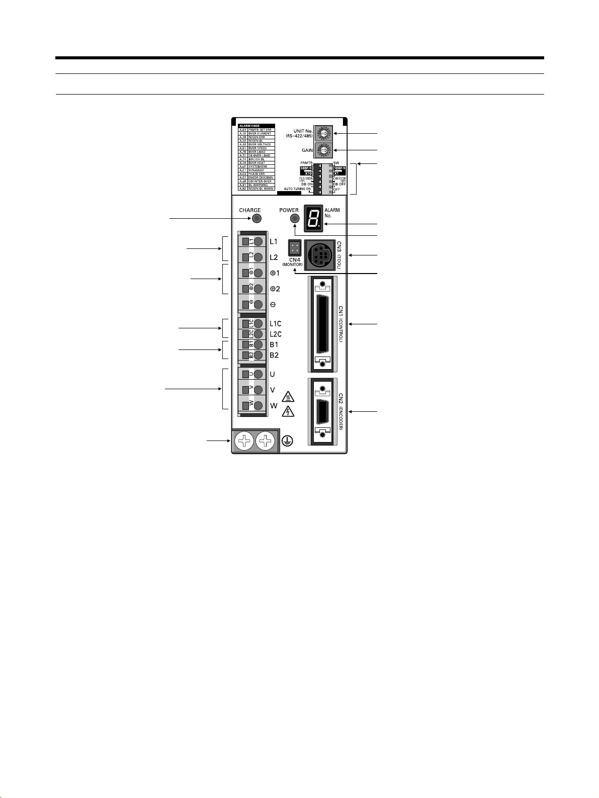
1-3 Servo Driver Nomenclature
Main-circuit power supply
indicator
Main-circuit power
supply input terminals
Chapter 1
Rotary switch for unit No. selection
Rotary switch for gain adjustment
Function selection switches:
• Switch/parameter setting enable switch
• Resolution setting
• Command pulse input setting
• Dynamic braking setting
• Online autotuning switch
Alarm display
Control-circuit power supply indicator
Communications connector (CN3)
DC reactor connection terminals
Control-circuit power supply
input terminals
External regeneration
resistance terminals
Servomotor power terminals
FG terminals for power supply and
servomotor power
Monitor output connector (CN4)
Control I/O connector (CN1)
Encoder input connector (CN2)
1-5
Page 24
Introduction
Chapter 1
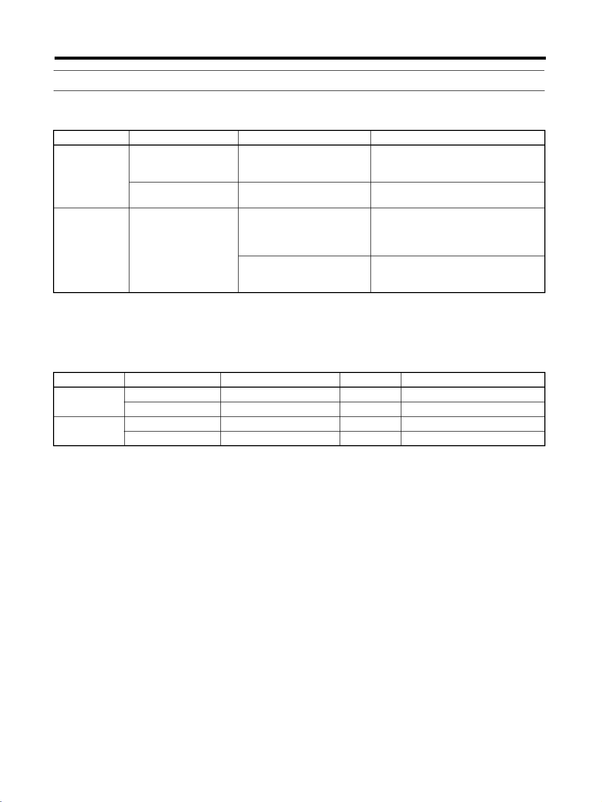
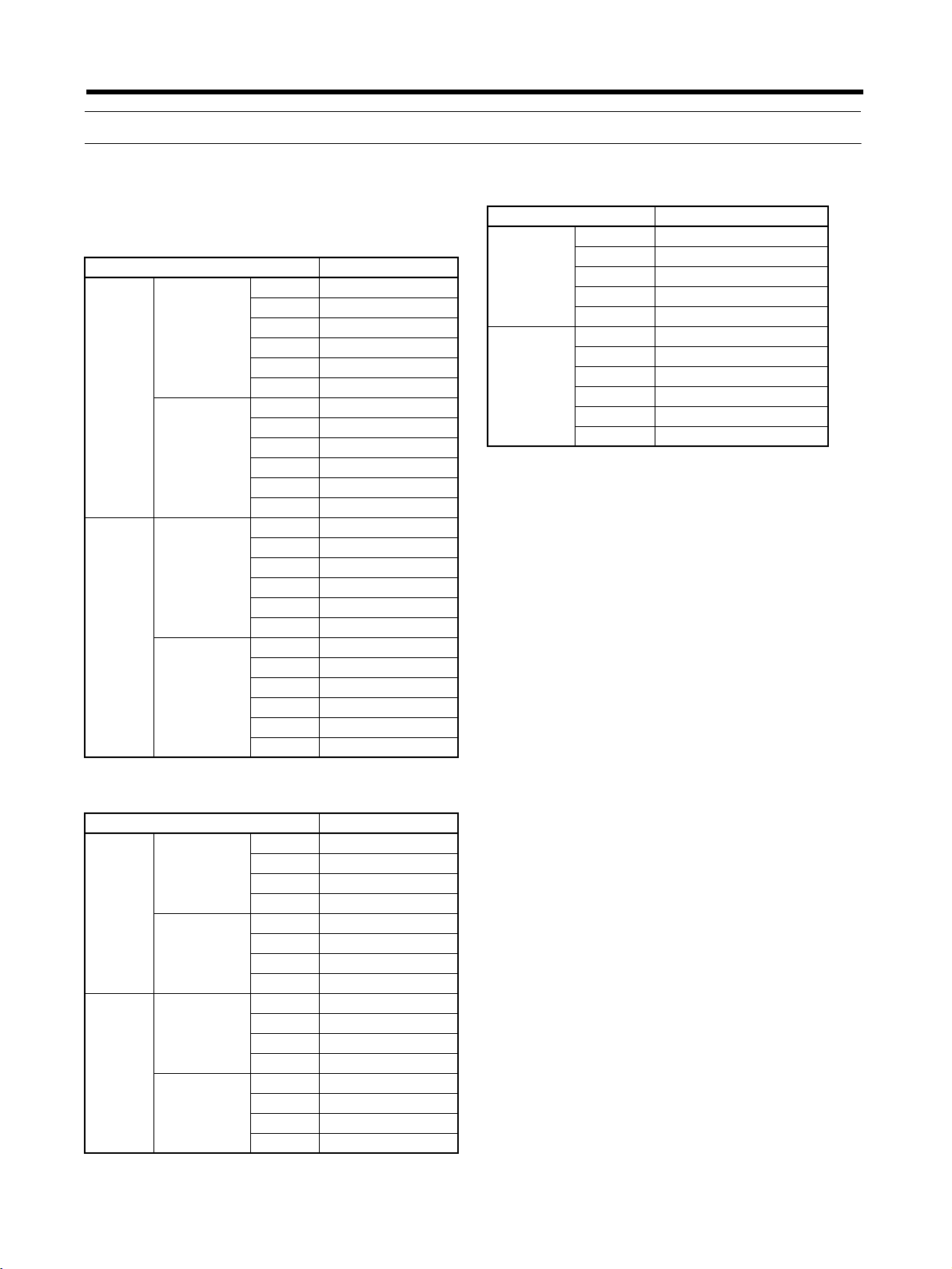
1-4 Applicable Standards
■ EC Directives
EC Directives Product Applicable standards Remarks
Low Voltage
Directive
EMC Directives AC Servo Drivers and
Note Installation under the conditions stipulated in 3-2-5 EMC-compatible Wiring must be met to
ensure conformance to EMC Directives.
AC Servo Drivers EN50178 Safety requirements for electrical
devices for measurement, control,
and research facilities
AC Servomotors IEC60034-1, -5, -8, -9
EN60034-1, -9
EN55011 class A group 1 Wireless interference and measure-
AC Servomotors
EN61000-6-2 Electromagnetic compatibility and
Rotating electrical equipment
ment methods for radio-frequency
devices for industry, science, and
medical application
immunity standards for industrial
environments
■ UL and cUL Standards
Standards Product Applicable standards File No. Remarks
UL AC Servo Drivers UL508C E179149 Power conversion devices
AC Servomotors UL1004 E179189 Electric motors
cUL AC Servo Drivers cUL C22.2 No. 14 E179149 Industrial control devices
AC Servomotors cUL C22.2 No. 100 E179189 Motors and generators
1-6
Page 25
Introduction
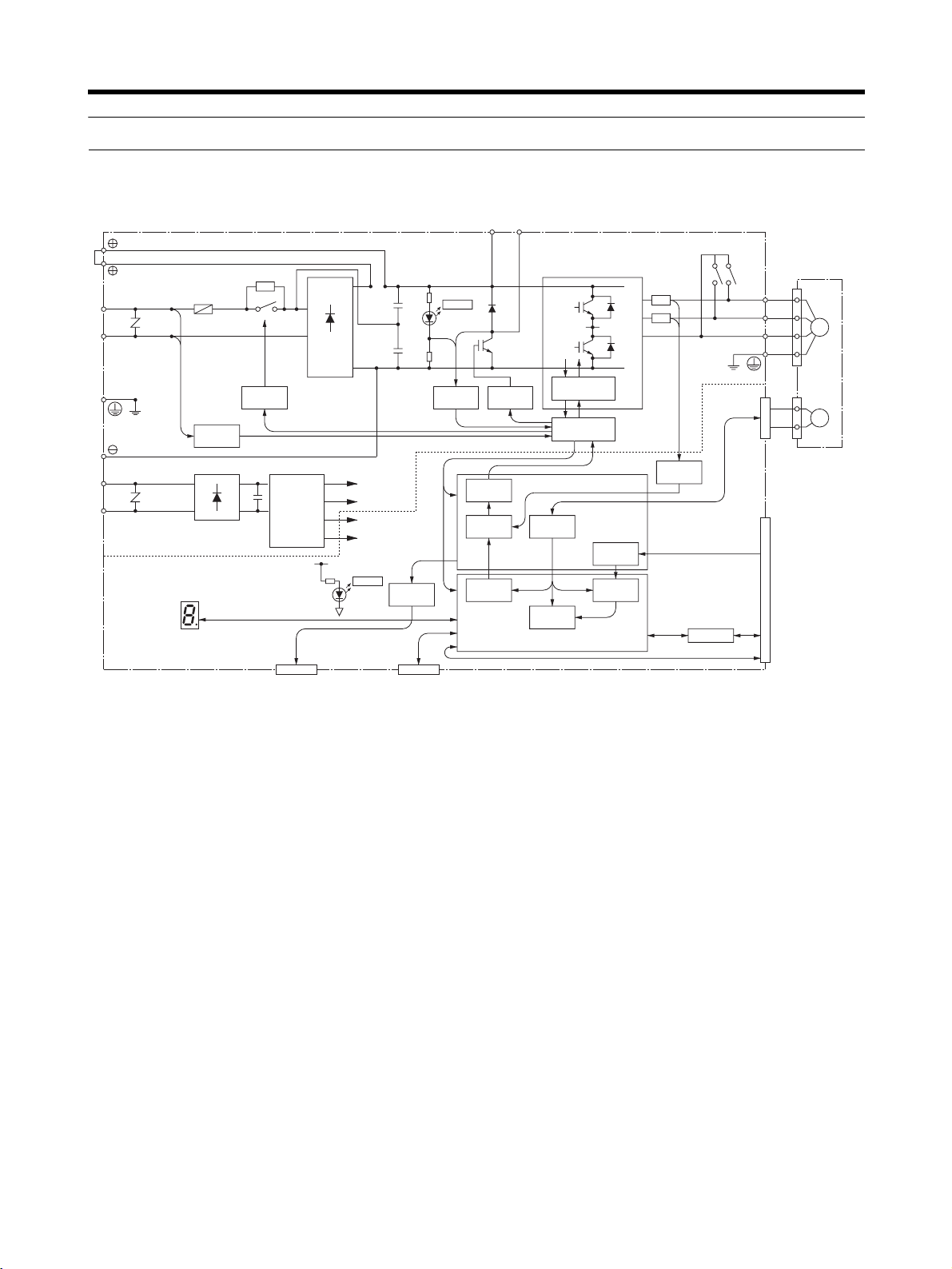
1-5 System Block Diagrams
■ 100 V AC: R7D-APA3L/-APA5L/-AP01L/-AP02L/-AP04L
AC Servo Driver
Gate drive
PWM
generation
Digital
current amp
Current
command
processing
Serial port
B1 B2
(See note.)
Encoder signal
P2
N2
Gate drive
overcurrent protection
Interface
processing
Speed
control
U
V
W
Current
detection
ASIC
Command
pulse
processing
Position
control
CPU
Note Only on R7D-AP04H/AP04L.
1
2
P1
R
T
N1
CHARGE
+
−
Voltage
detection
±5 V
+16.5 V
+5 V
L1
L2
L1C
L2C
Fuse
Voltage
detection
∼
∼
Relay
drive
+
+
DC/DC
−
−
conversion
±15 V
+5 V
POWER
Analog
voltage
0 V
Alarm code display
CN4
Analog monitor output
conversion
CN3
Parameter Unit/computer
Chapter 1
CN2
CN1
I/O
AC Servomotor
U
V
M
W
E
Command
pulse input
Control I/O
RS-422
1-7
Page 26
Introduction
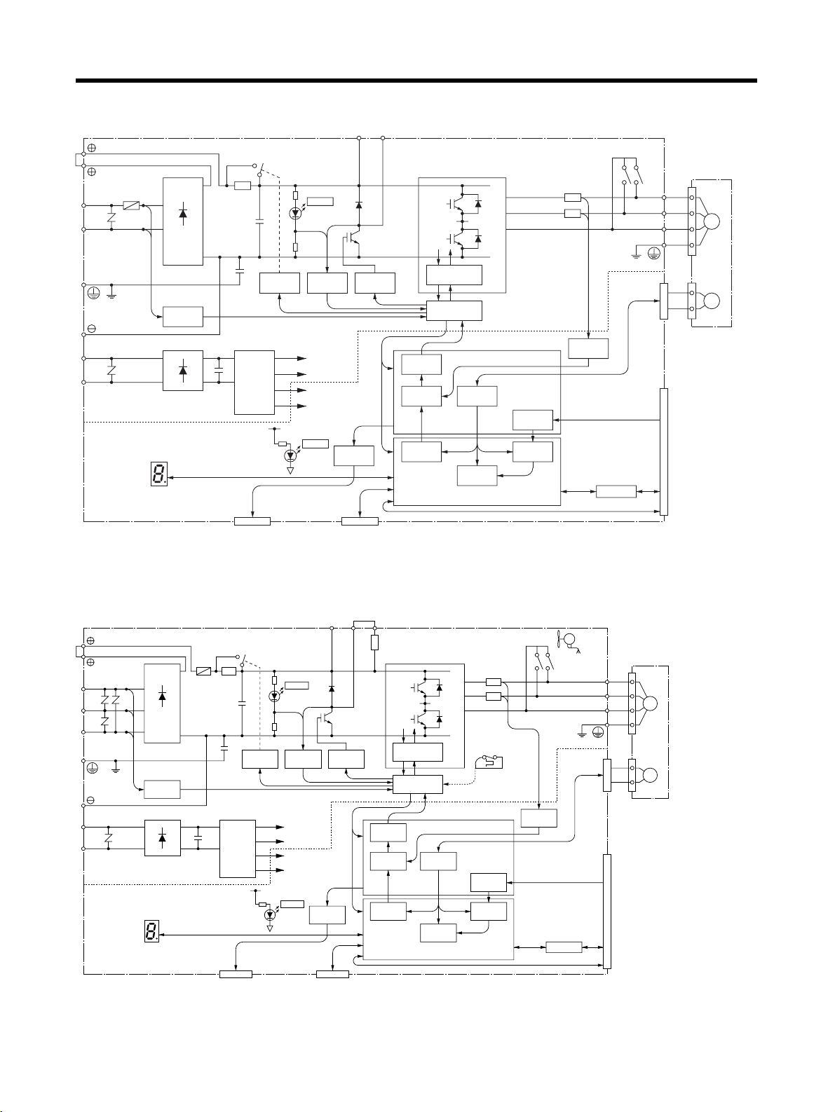
■ 200 V AC: R7D-APA3H/-APA5H/-AP01H/-AP02H/-AP04H
AC Servo Driver
1
B1 B2
Chapter 1
2
L1
L2
L1C
L2C
Fuse
R
T
Voltage
detection
∼
∼
Alarm code display
P1
N1
AC Servomotor
CHARGE
+
−
(See note.)
P2
U
V
W
U
V
M
W
N2
Gate drive
PWM
generation
Digital
current amp
Current
command
processing
Serial port
overcurrent protection
Interface
Encoder signal
processing
Speed
control
CN2
Current
detection
ASIC
CN1
Command
pulse
processing
Position
control
CPU
I/O
Command
pulse input
Control I/O
RS-422
Note Only on R7D-AP04H/AP04L.
E
Relay
+
+
DC/DC
−
−
conversion
drive
Voltage
detection
±5 V
+16.5 V
+5 V
Gate drive
±15 V
+5 V
POWER
Analog
voltage
conversion
0 V
CN4
Analog monitor output
CN3
Parameter Unit/computer
■ 200 V AC: R7D-AP08H
AC Servo Driver
1
2
L1
L2
L3
L1C
L2C
Alarm code display
R
S
T
Voltage
detection
∼
P
Fuse
CHARGE
+
−
N
Relay
detection
drive
+∼
+
DC/DC
−
−
conversion
±5 V
+16.5 V
+5 V
±15 V
+5 V
POWER
0 V
CN4
Analog monitor output
B1 B2 B3
Voltage
Gate
Analog
voltage
conversion
CN3
Parameter Unit/computer
drive
P
N
PWM
generation
Digital
current amp
Current
command
processing
Serial port
Gate drive over-
current protection
Interface
Encoder
processing
Speed
control
signal
FAN
±12 V
AC Servomotor
CN2
U
V
W
M
E
U
V
W
Thermistor
Current
detection
ASIC
CN1
Command
pulse
processing
Position
control
CPU
I/O
Command
pulse input
Control I/O
RS-422
1-8
Page 27

Chapter 2
Standard Models and Specifications
2-1 Standard Models
2-2 External and Mounted Dimensions
2-3 Servo Driver Specifications
2-4 Servomotor Specifications
2-5 Reduction Gear Specifications
2-6 Cable and Connector Specifications
2-7 Servo Relay Units and Cable Specifications
2-8 Parameter Unit Specifications
2-9 External Regeneration Resistor Specifications
2-10 DC Reactors
Page 28
Standard Models and Specifications
2-1 Standard Models
Chapter 2
■ Servomotors
● 3,000-r/min Cylinder-style Servomotors
Specifications Model
Without
brake
With
brake
Straight shaft
without key
Straight shaft
with key
Straight shaft
without key
Straight shaft
with key
30 W R7M-A03030
50 W R7M-A05030
100 W R7M-A10030
200 W R7M-A20030
400 W R7M-A40030
750 W R7M-A75030
30 W R7M-A03030-S1
50 W R7M-A05030-S1
100 W R7M-A10030-S1
200 W R7M-A20030-S1
400 W R7M-A40030-S1
750 W R7M-A75030-S1
30 W R7M-A03030-B
50 W R7M-A05030-B
100 W R7M-A10030-B
200 W R7M-A20030-B
400 W R7M-A40030-B
750 W R7M-A75030-B
30 W R7M-A03030-BS1
50 W R7M-A05030-BS1
100 W R7M-A10030-BS1
200 W R7M-A20030-BS1
400 W R7M-A40030-BS1
750 W R7M-A75030-BS1
■ Servo Drivers
Specifications Model
Single-phase
100 V AC
Single-phase
200 V AC
30 W R7D-APA3L
50 W R7D-APA5L
100 W R7D-AP01L
200 W R7D-AP02L
400 W R7D-AP04L
30 W R7D-APA3H
50 W R7D-APA5H
100 W R7D-AP01H
200 W R7D-AP02H
400 W R7D-AP04H
750 W R7D-AP08H
● 3,000-r/min Flat-style Servomotors
Specifications Model
Without
brake
With
brake
Straight shaft
without key
Straight shaft
with key
Straight shaft
without key
Straight shaft
with key
100 W R7M-AP10030
200 W R7M-AP20030
400 W R7M-AP40030
750 W R7M-AP75030
100 W R7M-AP10030-S1
200 W R7M-AP20030-S1
400 W R7M-AP40030-S1
750 W R7M-AP75030-S1
100 W R7M-AP10030-B
200 W R7M-AP20030-B
400 W R7M-AP40030-B
750 W R7M-AP75030-B
100 W R7M-AP10030-BS1
200 W R7M-AP20030-BS1
400 W R7M-AP40030-BS1
750 W R7M-AP75030-BS1
2-2
Page 29

Standard Models and Specifications
■ Reduction Gears (Straight Shaft with Key)
Chapter 2
● For Cylinder-style Servomotors
(Backlash = 3′ Max.)
Specifications Model
Servomotor
capacity
50 W 1/5 R7G-VRSFPB05B50
100 W 1/5 R7G-VRSFPB05B100
200 W 1/5 R7G-VRSFPB05B200
400 W 1/5 R7G-VRSFPB05C400
750 W 1/5 R7G-VRSFPB05C750
Reduction gears
(deceleration ratio)
1/9 R7G-VRSFPB09B50
1/15 R7G-VRSFPB15B50
1/25 R7G-VRSFPB25B50
1/9 R7G-VRSFPB09B100
1/15 R7G-VRSFPB15B100
1/25 R7G-VRSFPB25B100
1/9 R7G-VRSFPB09C400
1/15 R7G-VRSFPB15C400
1/25 R7G-VRSFPB25C200
1/9 R7G-VRSFPB09C400
1/15 R7G-VRSFPB15C400
1/25 R7G-VRSFPB25D400
1/9 R7G-VRSFPB09D750
1/15 R7G-VRSFPB15D750
1/25 R7G-VRSFPB25E750
● For Cylinder-style Servomotors
(Backlash = 45′ Max.)
Specifications Model
Servomotor
capacity
50 W 1/5 R7G-RGSF05B50
100 W 1/5 R7G-RGSF05B100
200 W 1/5 R7G-RGSF05B200
400 W 1/5 R7G-RGSF05C400
750 W 1/5 R7G-RGSF05C750
Reduction gears
(deceleration ratio)
1/9 R7G-RGSF09B50
1/15 R7G-RGSF15B50
1/25 R7G-RGSF25B50
1/9 R7G-RGSF09B100
1/15 R7G-RGSF15B100
1/25 R7G-RGSF25B100
1/9 R7G-RGSF09C400
1/15 R7G-RGSF15C400
1/25 R7G-RGSF25C400
1/9 R7G-RGSF09C400
1/15 R7G-RGSF15C400
1/25 R7G-RGSF25C400
1/9 R7G-RGSF09C750
1/15 R7G-RGSF15C750
1/25 R7G-RGSF25C750
Note There are no reduction gears for 30-W Servo-
motors.
● For Flat-style Servomotors
(Backlash = 3′ Max.)
Specifications Model
Servomotor
capacity
100 W 1/5 R7G-VRSFPB05B100P
200 W 1/5 R7G-VRSFPB05B200P
400 W 1/5 R7G-VRSFPB05C400P
750 W 1/5 R7G-VRSFPB05C750P
Reduction gears
(deceleration ratio)
1/9 R7G-VRSFPB09B100P
1/15 R7G-VRSFPB15B100P
1/25 R7G-VRSFPB25C100P
1/9 R7G-VRSFPB09C400P
1/15 R7G-VRSFPB15C400P
1/25 R7G-VRSFPB25C200P
1/9 R7G-VRSFPB09C400P
1/15 R7G-VRSFPB15C400P
1/25 R7G-VRSFPB25D400P
1/9 R7G-VRSFPB09D750P
1/15 R7G-VRSFPB15D750P
1/25 R7G-VRSFPB25E750P
Note There are no reduction gears for 30-W Servo-
motors.
● For Flat-style Servomotors
(Backlash = 45′ Max.)
Specifications Model
Servomotor
capacity
100 W 1/5 R7G-RGSF05B100P
200 W 1/5 R7G-RGSF05B200P
400 W 1/5 R7G-RGSF05C400P
750 W 1/5 R7G-RGSF05C750P
Reduction gears
(deceleration ratio)
1/9 R7G-RGSF09B100P
1/15 R7G-RGSF15B100P
1/25 R7G-RGSF25B100P
1/9 R7G-RGSF09C400P
1/15 R7G-RGSF15C400P
1/25 R7G-RGSF25C400P
1/9 R7G-RGSF09C400P
1/15 R7G-RGSF15C400P
1/25 R7G-RGSF25C400P
1/9 R7G-RGSF09C750P
1/15 R7G-RGSF15C750P
1/25 R7G-RGSF25C750P
2-3
Page 30

Standard Models and Specifications
Chapter 2
■ Servo Relay Units for CN1
Specifications Model
Servo
Relay Unit
Servo
Driver
Cable
Position
Control
Unit Cable
For CS1W-NC113/133
CJ1W-NC113/133
C200HW-NC113
C200H-NC112
3F88M-DRT141
(No communications supported.)
For CS1W-NC213/233/413/433
CJ1W-NC213/233/413/433
C200HW-NC213/413
C500-NC113/211
C200H-NC211
(No communications supported.)
For CS1W-HCP22
CQM1H-PLB21
CQM1-CPU43-V1
(No communications supported.)
For CS1W-NC213/233/413/433
CJ1W-NC213/233/413/433
(Communications supported.)
For CJ1M-CPU21/CPU22/
CPU23
For CS1W-HCP22-V1 and
FQM1-MMP21
No communications
supported.
Communications supported.
For FQM1-MMP21 1 m XW2Z-100J-B10
For CS1W-HCP22-V1 1 m XW2Z-100J-B12
For CQM1H-PLB21,
CQM1-CPU43-V1
For C200H-NC112 0.5 m XW2Z-050J-A4
For C200H-NC211,
C500-NC113/211
For CS1W-NC113,
C200HW-NC113
For CS1W-NC213/413,
C200HW-NC213/413
For CS1W-NC133 0.5 m XW2Z-050J-A12
For CS1W-NC233/433 0.5 m XW2Z-050J-A13
For CJ1W-NC113 0.5 m XW2Z-050J-A16
For CJ1W-NC213/413 0.5 m XW2Z-050J-A17
For CJ1W-NC133 0.5 m XW2Z-050J-A20
For CJ1W-NC233/433 0.5 m XW2Z-050J-A21
For CS1W-HCP22
(1 axis)
For CS1W-HCP22
(2 axes)
For 3F88M-DRT141 0.5 m XW2Z-050J-A25
1 m XW2Z-100J-B5
2 m XW2Z-200J-B5
1 m XW2Z-100J-B7
2 m XW2Z-200J-B7
2 m XW2Z-200J-B10
2 m XW2Z-200J-B12
0.5 m XW2Z-050J-A3
1 m XW2Z-100J-A3
1 m XW2Z-100J-A4
0.5 m XW2Z-050J-A5
1 m XW2Z-100J-A5
0.5 m XW2Z-050J-A8
1 m XW2Z-100J-A8
0.5 m XW2Z-050J-A9
1 m XW2Z-100J-A9
1 m XW2Z-100J-A12
1 m XW2Z-100J-A13
1 m XW2Z-100J-A16
1 m XW2Z-100J-A17
1 m XW2Z-100J-A20
1 m XW2Z-100J-A21
0.5 m XW2Z-050J-A22
1 m XW2Z-100J-A22
0.5 m XW2Z-050J-A23
1 m XW2Z-100J-A23
1 m XW2Z-100J-A25
XW2B-20J6-1B
XW2B-40J6-2B
XW2B-20J6-3B
XW2B-40J6-4A
XW2B-20J6-8A
XW2B-40J6-9A
XW2B-80J7-1A
Specifications Model
Position
Control
Unit Cable
For CJ1M-CPU21/
CPU22/CPU23
For FQM1-MMP21 for
general-purpose I/O
For CS1W-HCP22-V1
for general-purpose I/O
For FQM1-MMP21 for
special I/O
For CS1W-HCP22-V1
for special I/O
1 m XW2Z-100J-A26
0.5 m XW2Z-050J-A28
1 m XW2Z-100J-A28
0.5 m XW2Z-050J-A29
1 m XW2Z-100J-A29
0.5 m XW2Z-050J-A30
1 m XW2Z-100J-A30
0.5 m XW2Z-050J-A32
1 m XW2Z-100J-A32
■ Control Cables for CN1
Specifications Model
General-purpose Control Cable
(with Connector on one end)
Connector Terminal Block Cable 1 m R88A-CTU001N
Connector Terminal Blocks XW2B-40F5-P
1 m R88A-CPU001S
2 m R88A-CPU002S
2 m R88A-CTU002N
■ Integrated Servomotor Cables
Specifications Model
For Servomotors without
brakes (both Cylinder- and
Flat-style)
For Servomotors with
brakes (both Cylinder- and
Flat-style)
3 m R7A-CEA003S
5 m R7A-CEA005S
10 m R7A-CEA010S
15 m R7A-CEA015S
20 m R7A-CEA020S
3 m R7A-CEA003B
5 m R7A-CEA005B
10 m R7A-CEA010B
15 m R7A-CEA015B
20 m R7A-CEA020B
■ Separate Servomotor Cables
● Power Cables
Specifications Standard cable
For Servomotors without brakes
(both Cylinder- and
Flat-style)
For Servomotors with
brakes (both
Cylinderand Flatstyle)
3 m R88A-CAWA003S R88A-CAWA003SR
5 m R88A-CAWA005S R88A-CAWA005SR
10 m R88A-CAWA010S R88A-CAWA010SR
15 m R88A-CAWA015S R88A-CAWA015SR
20 m R88A-CAWA020S R88A-CAWA020SR
3 m R88A-CAWA003B R88A-CAWA003BR
5 m R88A-CAWA005B R88A-CAWA005BR
10 m R88A-CAWA010B R88A-CAWA010BR
15 m R88A-CAWA015B R88A-CAWA015BR
20 m R88A-CAWA020B R88A-CAWA020BR
model
Robot cable
model
● Encoder Cables
Specifications Standard cable
For Servomotors (Cylinder-style or
Flat-style)
3 m R7A-CRA003C R7A-CRA003CR
5 m R7A-CRA005C R7A-CRA005CR
10 m R7A-CRA010C R7A-CRA010CR
15 m R7A-CRA015C R7A-CRA015CR
20 m R7A-CRA020C R7A-CRA020CR
model
Robot cable
model
Note Use a robot cable if cable flexibility is required.
2-4
Page 31

Standard Models and Specifications
■ Peripheral Cable Connectors
Specifications Model
Analog Monitor Cable (CN4) 1 m R88A-CMW001S
Computer Monitor Cable (CN3) DOS 2 m R7A-CCA002P2
PC98 2 m R7A-CCA002P3
Control I/O Connector (CN1) R88A-CNU01C
Encoder Connector (CN2) R7A-CNA01R
Encoder Connector (Servomotor end) R7A-CNA02R
Communications Cable 1 m XW2Z-100J-C1
2 m XW2Z-200J-C1
■ Parameter Units
Specifications Model
Hand-held (with 1-m cable) R7A-PR02A
■ External Regeneration Resistors
Specifications Model
Resistor 220 W 47
■ DC Reactors
Specifications Model
For R7D-APA3L/APA5L/APA01L R88A-PX5063
For R7D-AP02L R88A-PX5062
For R7D-AP04L R88A-PX5061
For R7D-APA3H/APA5H/AP01H R88A-PX5071
For R7D-AP02H R88A-PX5070
For R7D-AP04H R88A-PX5069
For R7D-AP08H R88A-PX5061
Ω R88A-RR22047S
Chapter 2
■ Front-panel Brackets
Specifications Model
For the SMARTSTEP A Series R88A-TK01W
2-5
Page 32

Standard Models and Specifications
Chapter 2
2-2 External and Mounted Dimensions
2-2-1 Servo Drivers
■ Single-phase 100 V AC: R7D-APA3L/-APA5L/-AP01L/-AP02L (30 W to 200 W)
Single-phase 200 V AC: R7D-APA3H/-APA5H/-AP01H/-AP02H (30 W to 200 W)
● Wall Mounting
External dimensions
Mounted dimensions
Two, M4
5.5
160
55
(75) 130
17
● Front Panel Mounting (Using Mounting Brackets)
External dimensions
7.5(7.5)
5 dia. 24.5
52661.5
2
160
149.5±0.5
5
(5)
55
Mounted dimensions
7.5(7.5)
10
Two, M4
2-6
195
180
195
180±0.5
5
32.5
11.542
(168)
Page 33

Standard Models and Specifications
■ Single-phase 100 V AC: R7D-AP04L (400 W)
Single-phase 200 V AC: R7D-AP04H (400 W)
● Wall Mounting
External dimensions
5 dia.
Mounted dimensions
Chapter 2
5.5
Two, M4
160
149.5 5.5(5)
5
12
75
(75) 130
17
● Front Panel Mounting (Using Mounting Brackets)
External dimensions
7.5
52 1.5
5 dia.
24.5
2
160
149.5±0.5
12
(5)
75
Mounted dimensions
7.5(7.5)
10
Two, M4
195
180
(7.5)
195
180±0.5
5
32.5
11.542
(168) 66
2-7
Page 34

Standard Models and Specifications
■ Single-phase/Three-phase 200 V AC: R7D-AP08H (750 W)
● Wall Mounting
External dimensions
5 dia.
Mounted dimensions
5.5
Chapter 2
Two, M4
160
149.5 5.5(5)
90
(75) 180
17
160
149.5±0.5
(5)
● Front Panel Mounting (Using Mounting Brackets)
External dimensions Mounted dimensions
7.5(7.5)
5 dia.
52 12.5
24.5
2
7.5(7.5)
10
27
90
Two, M4
2-8
195
180
195
180±0.5
5
43.5
42
22.5
(168) 66
Page 35

Standard Models and Specifications
DRIVER PR
PR DRIVER
WRITE
B.B
INP
VCMP
TGON
REF
POWER
2-2-2 Parameter Unit
■ R7A-PR02A Hand-held Parameter Unit
70
B.B
INP
TGON
REF
POWER
1201000
VCMP
R7A–PR02A PARAMETER UNIT
RESET
SCROLL MODE/SET
1.5
17
Chapter 2
0.8
42
JOG
RUN
READ
DRIVER PR
6
DATA
WRITE
PR DRIVER
4.8 dia.
13.2 dia.
2-9
Page 36

Standard Models and Specifications
2-2-3 Servomotors
■ Cylinder-style Servomotors without a Brake
● 30 W/50 W/100 W R7M-A03030(-S1)/-A05030(-S1)/-A10030(-S1)
300±30
Chapter 2
6 dia.
19.5 20
9.5
7 dia.
300±30
11
LL 25
S dia.
30h7 dia.
Two, 4.3 dia.
46 dia.
21.5 5
Dimensions of shaft end with key (-S1)
b
40
14
4052.5
Model Dimensions (mm)
LL S b h t1
R7M-A03030-@ 69.5 6h6 2 2 1.2
R7M-A05030-@ 77 6h6 2 2 1.2
R7M-A10030-@ 94.5 8h6 3 3 1.8
■ Cylinder-style Servomotors with a Brake
● 30 W/50 W/100 W R7M-A03030-B(S1)/-A05030-B(S1)/-A10030-B(S1)
300±30
h
t1
6 dia. 7 dia.
19.5 27
9.5
11
LL 25
300±30
S dia.
Two, 4.3 dia.
30h7 dia.
21.5 5
46 dia.
Dimensions of shaft end with key (-BS1)
h
b
40
14
405 2.5
t1
Model Dimensions (mm)
LL S b h t1
R7M-A03030-B@ 101 6h6 2 2 1.2
R7M-A05030-B@ 108.5 6h6 2 2 1.2
R7M-A10030-B@ 135 8h6 3 3 1.8
2-10
Page 37

Standard Models and Specifications
■ Cylinder-style Servomotors without a Brake
● 200 W/400 W/750 W R7M-A20030(-S1)/-A40030(-S1)/-A75030(-S1)
300±30
Chapter 2
6 dia.
13
9
7 dia.
20
11
LL LR
300±30
G3
S dia.
21.5
Four, Z dia.
D1 dia.
D2 dia.
C
Dimensions of output section of 750-W Servomotors
2
Dimensions of shaft end with key (-S1)
C
QK
5
5
3
Model Dimensions (mm)
LL LR C D1 D2 G Z S QK
R7M-A20030-@ 96.5 30 60 70 50h7 6 5.5 14h6 20
R7M-A40030-@ 124.530607050h76 5.514h620
R7M-A75030-@ 14540809070h78 7 16h630
■ Cylinder-style Servomotors with a Brake
● 200 W/400 W/750 W R7M-A20030-B(S1)/-A40030-B(S1)/-A75030-B(S1)
300±30
Dimensions of output section of
6 dia. 7 dia.
13 27
9
11
LL LR
300±30
G3
S dia.
Four, Z dia.
D
D2 dia.
21.5
1 dia.
C
750-W Servomotors
2
Dimensions of shaft end with key (-BS1)
C
QK
5
5
3
Model Dimensions (mm)
LL LR C D1 D2 G Z S QK
R7M-A20030-B@ 13630607050h76 5.514h620
R7M-A40030-B@ 16430607050h76 5.514h620
R7M-A75030-B@ 189.540809070h78 7 16h630
2-11
Page 38

Standard Models and Specifications
Chapter 2
■ Flat-style Servomotors without a Brake
● 100 W/200 W/400 W/750 W R7M-AP10030(-S1)/-AP20030(-S1)/-AP40030(-S1)/AP75030(-S1)
300±30
6 dia.7 dia.
13
300±30
A2
A1
A5
GF
LL LR
S dia.
D1 dia.
D2 dia.
A3
A4
Dimensions of shaft end with key (-S1)
h
b
C
QK
C
Four, Z dia.
t1
Model Dimensions (mm)
Basic servomotor dimensions With key (shaft
Cable outlet dimensions
end dimensions)
LLLRCD1 D2 F G Z SQKb h t1A1A2A3A4A5
R7M-AP10030-@ 62 25 60 70 50h7 3 6 5.5 8h6 14 3 3 1.8 9 18 25 21 14
R7M-AP20030-@ 67 30 80 90 70h7 3 8 7 14h6 16 5 5 3
R7M-AP40030-@ 87
R7M-AP75030-@ 86.5 40 120 145 110h7 3.5 10 10 16h6 22 5 5 3 28 38 19
■
Flat-style Servomotors with a Brake
● 100 W/200 W/400 W/750 W R7M-AP10030-B(S1)/-AP20030-B(S1)/-AP40030-B(S1)/AP75030-B(S1)
300±30
6 dia.
7 dia.
13
A2
A1
A5
LL LR
300±30
D1 dia.
S dia.
D2 dia.
GF
A3
A4
Dimensions of shaft end with key (-BS1)
h
b
C
QK
C
Four, Z dia.
t1
Model Dimensions (mm)
Basic servomotor dimensions With key (shaft
Cable outlet dimensions
end dimensions)
LL LR C D1 D2 F G Z S QK b h t1 A1 A2 A3 A4 A5
R7M-AP10030-B@ 91 25 60 70 50h7 3 6 5.5 8h6 14 3 3 1.8 9 18 25 21 23
R7M-AP20030-B@ 98.5 30 80 90 70h7 3 8 7 14h6 16 5 5 3
R7M-AP40030-B@ 118.5
R7M-AP75030-B@ 120 40 120 145 110h7 3.5 10 10 16h6 22 5 5 3 28 38 26
2-12
Page 39

Standard Models and Specifications
Chapter 2
2-2-4 Reduction Gears
■ For Cylinder-style Servomotors (Backlash = 3′ Max.)
Model Dimensions (mm)
LM LR C1 C2 D1 D2 D3 D4 E3 F G S T Z1 Z2 AT* l Key dimensions
QK b h t1
50 W 1/5 R7G-VRSFPB05B50 67.5 32 52 40 46 60 50 45 10 3 6 12 20 M4 M5 M3 12 16 4 4 2.5 0.55
1/9 R7G-VRSFPB09B50 67.5 32 52 40 46 60 50 45 10 3 6 12 20 M4 M5 M3 12 16 4 4 2.5 0.55
1/15 R7G-VRSFPB15B50 78 32 52 40 46 60 50 45 10 3 6 12 20 M4 M5 M3 12 16 4 4 2.5 0.7
1/25 R7G-VRSFPB25B50 78 32 52 40 46 60 50 45 10 3 6 12 20 M4 M5 M3 12 16 4 4 2.5 0.7
100 W 1/5 R7G-VRSFPB05B100 67.5 32 52 40 46 60 50 45 10 3 6 12 20 M4 M5 M3 12 16 4 4 2.5 0.55
1/9 R7G-VRSFPB09B100 67.5 32 52 40 46 60 50 45 10 3 6 12 20 M4 M5 M3 12 16 4 4 2.5 0.55
1/15 R7G-VRSFPB15B100 78 32 52 40 46 60 50 45 10 3 6 12 20 M4 M5 M3 12 16 4 4 2.5 0.7
1/25 R7G-VRSFPB25C100 92 50 78 40 46 90 70 62 17 3 6 19 30 M4 M6 M3 20 22 6 6 3.5 1.7
200 W 1/5 R7G-VRSFPB05B200 72.5 32 52 60 70 60 50 45 10 3 10 12 20 M5 M5 M4 12 16 4 4 2.5 0.72
1/9 R7G-VRSFPB09C400 89.5 50 78 60 70 90 70 62 17 3 8 19 30 M5 M6 M4 20 22 6 6 3.5 1.7
1/15 R7G-VRSFPB15C400 100 50 78 60 70 90 70 62 17 3 8 19 30 M5 M6 M4 20 22 6 6 3.5 2.1
1/25 R7G-VRSFPB25C400 100 50 78 60 70 90 70 62 17 3 8 19 30 M5 M6 M4 20 22 6 6 3.5 2.1
400 W 1/5 R7G-VRSFPB05C400 89.5 50 78 60 70 90 70 62 17 3 8 19 30 M5 M6 M4 20 22 6 6 3.5 1.7
1/9 R7G-VRSFPB09C400 89.5 50 78 60 70 90 70 62 17 3 8 19 30 M5 M6 M4 20 22 6 6 3.5 1.7
1/15 R7G-VRSFPB15C400 100 50 78 60 70 90 70 62 17 3 8 19 30 M5 M6 M4 20 22 6 6 3.5 2.1
1/25 R7G-VRSFPB25D400 104 61 98 60 70 115 90 75 18 5 8 24 40 M5 M8 M4 20 30 8 7 4 3.2
750 W 1/5 R7G-VRSFPB05C750 93.5 50 78 80 90 90 70 62 17 3 10 19 30 M6 M6 M4 20 22 6 6 3.5 2.1
1/9 R7G-VRSFPB09D750 97.5 61 98 80 90 115 90 75 18 5 10 24 40 M6 M8 M4 20 30 8 7 4 3.4
1/15 R7G-VRSFPB15D750 110 61 98 80 90 115 90 75 18 5 10 24 40 M6 M8 M4 20 30 8 7 4 3.8
1/25 R7G-VRSFPB25E750 135 75 125 80 90 135 110 98 17 5 10 32 55 M6 M10 M4 20 45 10 8 5 7.2
* "AT" in the table refers to the set bolt.
Weig ht
(kg)
External Diagrams
Four, Z1 dia.
D1 dia.
@C2
Set bolt (AT)
G
LM
Key dimensions
QK
E3
F
D4 dia.
Sh6 dia.
T
LR
b
t1
h
D3h7 dia.
Four, Z2 dia.
(effective depth: l)
D2 dia.
@C1
2-13
Page 40

Standard Models and Specifications
Chapter 2
■ For Cylinder-style Servomotors (Backlash = 45′ Max.)
Model Dimensions (mm)
LM LR C1 C2 D1 D2 D3 D4 E3 F G S T Z1 Z2 AT* l Key dimensions
QK b h t1
50 W 1/5 R7G-RGSF05B50 67.5 32 52 40 46 60 50 45 10 3 6 12 20 M4 M5 M3 12 16 4 4 2.5 0.55
1/9 R7G-RGSF09B50 67.5 32 52 40 46 60 50 45 10 3 6 12 20 M4 M5 M3 12 16 4 4 2.5 0.55
1/15R7G-RGSF15B5078 3252 404660 50 451036 1220M4M5M31216442.50.70
1/25R7G-RGSF25B5078 3252 404660 50 451036 1220M4M5M31216442.50.70
100 W 1/5 R7G-RGSF05B100 67.5 32 52 40 46 60 50 45 10 3 6 12 20 M4 M5 M3 12 16 4 4 2.5 0.55
1/9 R7G-RGSF09B100 67.5 32 52 40 46 60 50 45 10 3 6 12 20 M4 M5 M3 12 16 4 4 2.5 0.55
1/15 R7G-RGSF15B100 78 32 52 40 46 60 50 45 10 3 6 12 20 M4 M5 M3 12 16 4 4 2.5 0.70
1/25 R7G-RGSF25B100 78 32 52 40 46 60 50 45 10 3 6 12 20 M4 M5 M3 12 16 4 4 2.5 0.70
200 W 1/5 R7G-RGSF05B200 72.5 32 52 60 70 60 50 45 10 3 10 12 20 M5 M5 M4 12 16 4 4 2.5 0.72
1/9 R7G-RGSF09C400 89.5 50 78 60 70 90 70 62 17 3 8 19 30 M5 M6 M4 20 22 6 6 3.5 1.7
1/15R7G-RGSF15C400100 5078 60 7090 70 621738 1930M5M6M42022663.52.1
1/25R7G-RGSF25C400100 5078 60 7090 70 621738 1930M5M6M42022663.52.1
400 W 1/5 R7G-RGSF05C400 89.5 50 78 60 70 90 70 62 17 3 8 19 30 M5 M6 M4 20 22 6 6 3.5 1.7
1/9 R7G-RGSF09C400 89.5 50 78 60 70 90 70 62 17 3 8 19 30 M5 M6 M4 20 22 6 6 3.5 1.7
1/15R7G-RGSF15C400100 5078 60 7090 70 621738 1930M5M6M42022663.52.1
1/25R7G-RGSF25C400100 5078 60 7090 70 621738 1930M5M6M42022663.52.1
750 W 1/5 R7G-RGSF05C750 93.5 50 78 80 90 90 70 62 17 3 10 19 30 M6 M6 M4 20 22 6 6 3.5 2.1
1/9 R7G-RGSF09C750 93.5 50 78 80 90 90 70 62 17 3 10 19 30 M6 M6 M4 20 22 6 6 3.5 2.1
1/15 R7G-RGSF15C750 110 50 78 80 90 90 70 62 17 3 10 19 30 M6 M6 M4 20 22 6 6 3.5 2.5
1/25 R7G-RGSF25C750 110 50 78 80 90 90 70 62 17 3 10 19 30 M6 M6 M4 20 22 6 6 3.5 2.5
Weig ht
(kg)
External Diagrams
Four, Z1 dia.
D1 dia.
@C2
Set bolt (AT)
G
LM
Key dimensions
* "AT" in the table refers to the set bolt.
E3
F
D4 dia.
Sh6 dia.
T
LR
b
D3h7 dia.
Four, Z2 dia.
(effective depth: l)
D2 dia.
@C1
2-14
QK
t1
h
Page 41

Standard Models and Specifications
Chapter 2
■ For Flat-style Servomotors (Backlash = 3′ Max.)
Model Dimensions (mm)
LM LR C1 C2 D1 D2 D3 D4 E3 F G S T Z1 Z2 AT* l Key dimensions
QK b h t1
100 W 1/5 R7G-VRSFPB05B100P 72.5 32 52 60 70 60 50 45 10 3 10 12 20 M5 M5 M4 12 16 4 4 2.5 0.72
1/9 R7G-VRSFPB09B100P 72.5 32 52 60 70 60 50 45 10 3 10 12 20 M5 M5 M4 12 16 4 4 2.5 0.72
1/15 R7G-VRSFPB15B100P 83 32 52 60 70 60 50 45 10 3 10 12 20 M5 M5 M4 12 16 4 4 2.5 0.77
1/25 R7G-VRSFPB25C100P 92 50 78 60 70 90 70 62 17 3 10 19 30 M5 M6 M3 20 22 6 6 3.5 1.8
200 W 1/5 R7G-VRSFPB05B200P 72.5 32 52 80 90 60 50 45 10 3 12 12 20 M6 M5 M4 12 16 4 4 2.5 0.85
1/9 R7G-VRSFPB09C400P 93.5 50 78 80 90 90 70 62 17 3 12 19 30 M6 M6 M4 20 22 6 6 3.5 1.8
1/15 R7G-VRSFPB15C400P 100 50 78 80 90 90 70 62 17 3 12 19 30 M6 M6 M4 20 22 6 6 3.5 2.2
1/25 R7G-VRSFPB25C200P 100 50 78 80 90 90 70 62 17 3 12 19 30 M6 M6 M4 20 22 6 6 3.5 2.2
400 W 1/5 R7G-VRSFPB05C400P 93.5 50 78 80 90 90 70 62 17 3 10 19 30 M6 M6 M4 20 22 6 6 3.5 1.8
1/9 R7G-VRSFPB09C400P 93.5 50 78 80 90 90 70 62 17 3 12 19 30 M6 M6 M4 20 22 6 6 3.5 1.8
1/15 R7G-VRSFPB15C400P 100 50 78 80 90 90 70 62 17 3 12 19 30 M6 M6 M4 20 22 6 6 3.5 2.2
1/25 R7G-VRSFPB25D400P 109 61 98 80 90 115 90 75 18 5 12 24 40 M6 M8 M4 20 30 8 7 4 3.4
750 W 1/5 R7G-VRSFPB05C750P 98 50 78 120 145 90 70 62 17 3 15 19 30 M8 M6 M4 20 22 6 6 3.5 2.6
1/9 R7G-VRSFPB09D750P 97.5 61 98 120 145 115 90 75 18 5 15 24 40 M8 M8 M4 20 30 8 7 4 3.8
1/15 R7G-VRSFPB15D750P 110 61 98 120 145 115 90 75 18 5 15 24 40 M8 M8 M4 20 30 8 7 4 4.2
1/25 R7G-VRSFPB25E750P 155 75 125 120 145 135 110 98 17 5 15 32 55 M8 M10 M4 20 45 10 8 5 7.8
* "AT" in the table refers to the set bolt.
Weig ht
(kg)
External Diagrams
D1 dia.
@C2
Set bolt (AT)
Four, Z1 dia.
G
Key dimensions
QK
LM
E3
F
D4 dia.
Sh6 dia.
T
LR
b
t1
D3h7 dia.
Four, Z2 dia.
(effective depth: l)
D2 dia.
@C1
h
2-15
Page 42

Standard Models and Specifications
Chapter 2
■ For Flat-style Servomotors (Backlash = 45′ Max.)
Model Dimensions (mm)
LM LR C1 C2 D1 D2 D3 D4 E3 F G S T Z1 Z2 AT* l Key dimensions
QK b h t1
100 W 1/5 R7G-RGSF05B100P 72.5 32 52 60 70 60 50 45 10 3 10 12 20 M5 M5 M4 12 16 4 4 2.5 0.72
1/9 R7G-RGSF09B100P 72.5 32 52 60 70 60 50 45 10 3 10 12 20 M5 M5 M4 12 16 4 4 2.5 0.72
1/15 R7G-RGSF15B100P 78 32 52 60 70 60 50 45 10 3 8 12 20 M5 M5 M4 12 16 4 4 2.5 0.77
1/25 R7G-RGSF25B100P 78 32 52 60 70 60 50 45 10 3 8 12 20 M5 M5 M4 12 16 4 4 2.5 0.77
200 W 1/5 R7G-RGSF05B200P 72.5 32 52 80 90 60 50 45 10 3 12 12 20 M6 M5 M4 12 16 4 4 2.5 0.85
1/9 R7G-RGSF09C400P 89.5 50 78 80 90 90 70 62 17 3 12 19 30 M6 M6 M4 20 22 6 6 3.5 1.8
1/15 R7G-RGSF15C400P 100 50 78 80 90 90 70 62 17 3 12 19 30 M6 M6 M4 20 22 6 6 3.5 2.2
1/25 R7G-RGSF25C400P 100 50 78 80 90 90 70 62 17 3 12 19 30 M6 M6 M4 20 22 6 6 3.5 2.2
400 W 1/5 R7G-RGSF05C400P 89.5 50 78 80 90 90 70 62 17 3 12 19 30 M6 M6 M4 20 22 6 6 3.5 1.8
1/9 R7G-RGSF09C400P 89.5 50 78 80 90 90 70 62 17 3 12 19 30 M6 M6 M4 20 22 6 6 3.5 1.8
1/15 R7G-RGSF15C400P 100 50 78 80 90 90 70 62 17 3 12 19 30 M6 M6 M4 20 22 6 6 3.5 2.2
1/25 R7G-RGSF25C400P 100 50 78 80 90 90 70 62 17 3 12 19 30 M6 M6 M4 20 22 6 6 3.5 2.2
750 W 1/5 R7G-RGSF05C750P 93.5 50 78 120 145 90 70 62 17 3 15 19 30 M8 M6 M4 20 22 6 6 3.5 2.5
1/9 R7G-RGSF09C750P 93.5 50 78 120 145 90 70 62 17 3 15 19 30 M8 M6 M4 20 22 6 6 3.5 2.5
1/15 R7G-RGSF15C750P 110 50 78 120 145 90 70 62 17 3 15 19 30 M8 M6 M4 20 22 6 6 3.5 2.9
1/25 R7G-RGSF25C750P 110 50 78 120 145 90 70 62 17 3 15 19 30 M8 M6 M4 20 22 6 6 3.5 2.9
* "AT" in the table refers to the set bolt.
Weight
External Diagrams
(kg)
D1 dia.
@C2
Set bolt (AT)
Four, Z1 dia.
G
Key dimensions
QK
LM
E3
F
D4 dia.
Sh6 dia.
T
LR
b
t1
h
Four, Z2 dia.
(effective depth: l)
D2 dia.
D3h7 dia.
@C1
2-16
Page 43

Standard Models and Specifications
Chapter 2
2-3 Servo Driver Specifications
■ SMARTSTEP A-series R7D-AP@ Servo Drivers
Select a Servo Driver to match the Servomotor to be used.
2-3-1 General Specifications
Item Specifications
Ambient operating temperature 0 to 55
Ambient operating humidity 90% max. (with no condensation)
Ambient storage temperature –20 to 85
Ambient storage humidity 90% max. (with no condensation)
Storage and operating atmo-
sphere
Vibration resistance 10 to 55 Hz in X, Y, and Z directions with 0.1-mm double amplitude; accel-
Impact resistance
Insulation resistance Between power line terminals and case: 0.5 M
Dielectric strength Between power line terminals and case: 1,500 V AC for 1 min at 50/60 Hz
Protective structure Built into panel (IP10).
No corrosive gasses.
eration: 4.9 m/s
Acceleration 19.6 m/s
Between each control signal and case: 500 V AC for 1 min
°C
°C
2
max.
2
max., in X, Y, and Z directions, three times
Ω min. (at 500 V DC)
Note 1. The above items reflect individual evaluation testing. The results may differ under compound
conditions.
Note 2. Absolutely do not conduct a withstand voltage test with a Megger tester on the Servo Driver.
If such tests are conducted, internal elements may be damaged.
Note 3. Depending on the operating conditions, some Servo Driver parts will require maintenance.
Refer to 5-5 Periodic Maintenance for details.
Note 4. The service life of the Servo Driver is 50,000 hours at an average ambient temperature of
°C at 80% of the rated torque.
40
2-17
Page 44

Standard Models and Specifications
Chapter 2
2-3-2 Performance Specifications
■ Control Specifications
● 100-V AC Input Type
Item R7D-APA3L R7D-APA5L R7D-AP01L R7D-AP02L R7D-AP04L
Continuous output current (rms)
Momentary maximum output current (rms)
Input power
supply
Heating value Main cir-
Control method All-digital servo
Speed feedback 2,000 pulses/revolution, incremental encoder
Inverter method PWM method based on IGBT
PWM frequency 11.7 kHz
Maximum applicable fre-
quency (command pulse
application)
Weight Approx. 0.8 kg Approx. 0.8 kg Approx. 0.8 kg Approx. 0.8 kg Approx. 1.1 kg
Applicable Servomotor
wattage
Applicable
Servomotor
(R7M-)
Main circuits
Control
circuits
cuits
Control
circuits
Cylinderstyle
Flat-style – – AP10030 AP20030 AP40030
0.42 A 0.6 A 0.89 A 2.0 A 2.6 A
1.3 A1.9 A2.8 A6.0 A8.0 A
Single-phase 100/115 V AC (85 to 127 V) 50/60 Hz (double voltage method)
Single-phase 100/115 V AC (85 to 127 V) 50/60 Hz
3.1 W4.6 W6.7 W13.3 W20.0 W
13 W13 W13 W13 W13 W
250 kpps
30 W 50 W 100 W 200 W 400 W
A03030 A05030 A10030 A20030 A40030
● 200-V AC Input Type (Single-phase Input)
Item R7D-
APA3H
Continuous output current (rms)
Momentary maximum
output current (rms)
Input power
supply
Heating
value
Control method All-digital servo
Main circuits
Control
circuits
Main circuits
Control
circuits
0.42 A 0.6 A 0.89 A 2.0 A 2.6 A 4.4 A
1.3 A 1.9 A 2.8 A 6.0 A 8.0 A 13.9 A
Single-phase 200/230 V AC (170 to 253 V) 50/60 Hz (for R7D–AP08H only, threephase input possible)
Single-phase 200/230 V AC (170 to 253 V) 50/60 Hz
3.1 W 4.6 W 6.7 W 13.3 W 20 W 47 W
20 W 20 W 20 W 20 W 20 W 20 W
R7D-
APA5H
2-18
R7D-
AP01H
R7D-
AP02H
R7D-
AP04H
R7D-
AP08H
Page 45

Standard Models and Specifications
Chapter 2
Item R7D-
APA3H
Speed feedback 2,000 pulses/revolution, incremental encoder
Inverter method PWM method based on IGBT
PWM frequency 11.7 kHz
Maximum applicable
frequency (command
pulse application)
Weight Approx.
Applicable Servomotor
wattage
Applicable
Servomotor
(R7M-)
Cylindertype
Flat-type – – AP10030 AP20030 AP40030 AP75030
250 kpps
0.8 kg
30 W 50 W 100 W 200 W 400 W 750 W
A03030 A05030 A10030 A20030 A40030 A75030
R7D-
APA5H
Approx.
0.8 kg
R7D-
AP01H
Approx.
0.8 kg
Approx.
0.8 kg
2-3-3 Terminal Block Specifications
Signal Function Condition
L1 Main circuits power
L2
L3
+1 DC Reactor termi+2
– Main circuit DC out-
L1C Control circuits
L2C
B1 External regeneraB2
B3
UServomotor conVWhite
WBlue
supply input
nal for power supply harmonic
control
put (Reverse)
power supply input
tion resistance connection terminals
nection terminals
Frame ground This is the ground terminal. Ground to a minimum of 100
R7D–AP@H: Single-phase 200/230 V AC (170 to 253 V AC) 50/60 Hz
R7D–AP@L: Single-phase 100/115 V AC (85 to 127 V AC) 50/60 Hz
Note: Only the R7D–AP08H (750 W) has an L3 terminal, enabling three-
phase input: Three-phase 200/230 V AC (170 to 253 V AC) 50/60 Hz
Normally short-circuit between +1 and +2.
If harmonic control measures are required, connect a DC Reactor between +1
and +2.
Do not connect anything.
R7D-AP@H: Single-phase 200/230 V AC (170 to 253 V AC) 50/60 Hz
R7D-AP@L: Single-phase 100/115 V AC (85 to 127 V AC) 50/60 Hz
30 to 200 W: No External Regeneration Resistor can be connected.
400 W: This terminal does not normally need to be connected. If regenerative
energy is high, connect an External Regeneration Resistor between B1 and
B2.
750 W: Normally shorted between B2 and B3. If there is high regenerative
energy, remove the short bar between B2 and B3 and connect an External
Regeneration Resistor between B1 and B2.
Red These are the terminals for outputs to the Servomotor. Be sure to
wire these terminals correctly.
Green/
Ye l l o w
R7D-
AP02H
R7D-
AP04H
Approx.
1.1 kg
Ω (class D, class 3).
R7D-
AP08H
Approx.
1.7 kg
2-19
Page 46

Standard Models and Specifications
2-3-4 Control I/O Specifications (CN1)
■ Control I/O and External Signals for Position Control
200 Ω
Reverse pulse
Forward pulse
Deviation
counter reset
+CW
−CW
+CCW
−CCW
+ECRST
−ECRST
1
2
3
4
5
6
200 Ω
200 Ω
(See
note 2.)
(See
note 2.)
(See
note 2.)
(See
note 2.)
INP8
Positioning
completed output
BKIR7
Brake interlock
OGND
10
Z32
Phase Z
ZCOM
33
ALM34
Alarm output
ALMCOM
35
Chapter 2
Maximum operating
voltage: 30 V DC
Maximum Output
Current:
Phase Z: 20 mA DC
Other than Phase Z:
50 mA DC
RUN command
Alarm reset
+24VIN24 V DC
13
14RUN
18RESET
3.3 k
3.3 k
22
23 TXD−
20 RXD+
21 RXD−
24 RT
Shell
TXD+
Transmission data
Reception data
Terminating
resistance terminal
FG
Frame ground
(See note 1.)
Note 1. Interface for RS-422:
• Applicable line driver: T.I. SN75174, MC3487 or equivalent
• Applicable line receiver: T.I. SN75175, MC3486 or equivalent
Note 2. Automatic-reset fuses are used for output protection. If overcurrent causes the fuse to oper-
ate, current will not flow, and after a fixed period of time it will automatically reset.
2-20
Page 47

Standard Models and Specifications
■ Control I/O Signals
● CN1 Control Inputs
Pin
Signal name Function Contents
No.
1 +PULS/CW/A Feed pulses, reverse
2–PULS/CW/A
3 +SIGN/CCW/B Direction signal, for4 –SIGN/CCW/B
5 +ECRST Deviation counter
6 –ECRST
pulses, or 90
difference pulses
(phase A)
ward pulses, or 90
phase difference
pulses (phase B)
reset
° phase
Pulse string input terminals for position commands.
Line-driver input: 7 mA at 3 V
Maximum response frequency: 250 kpps
Open-collector input: 7 to 15 mA
Maximum response frequency: 250 kpps
°
Any of the following can be selected by means of a Pn200.0
setting: feed pulses or direction signals (PULS/SIGN); forward
or reverse pulses (CW/CCW); 90
signals (A/B).
Line-driver input: 7 mA at 3 V
Open-collector input: 7 to 15 mA
ON: Pulse commands prohibited and deviation counter cleared.
Chapter 2
° phase difference (phase A/B)
Note Input for at least 20
13 +24VIN +24-V power supply
input for control DC
14 RUN RUN command input ON: Servo ON (Starts power to Servomotor.)
18 RESET Alarm reset input ON: Servo alarm status is reset.
● CN1 Control Outputs
Pin
No.
32 Z Phase Z output Outputs the Encoder’s phase Z. (1 pulse/revolution)
33 ZCOM
34 ALM
35 ALMCOM
7 BKIR Brake interlock output Outputs the holding brake timing signals.
8 INP Positioning completed
10 OGND
Note An open-collector output interface is used for pin-7 and -8 sequence outputs. (Maximum operating volt-
Signal
name
Alarm output When the Servo Driver generates an alarm, the output turns
output
Output ground common Ground common for sequence outputs (pins 7 and 8).
age: 30 V DC; maximum output current: 50 mA)
Function Contents
Power supply input terminal (+24 V DC) for sequence inputs
(pins 14 and 18).
Open collector output (maximum output voltage: 30 V DC max;
maximum output current: 20 mA)
OFF. Open collector output (maximum operating voltage: 30 V
DC; maximum output current: 50 mA)
ON when the position error is within the positioning completed
range (Pn500).
µs.
2-21
Page 48

Standard Models and Specifications
● Interface for RS-422
Pin
Signal name Function Contents
No.
20 RXD+
21 RXD–
22 TXD+
23 TXD–
24 RT
19 GND
■ CN1: Pin Arrangement
Reception data Interface for RS-422A transmission and reception.
Transmission data
Terminating resistance terminal Connect to pin 21 (RXD–) on the end Unit.
RS-422A ground Ground for RS-422A.
Chapter 2
−PULS
2
/−CW/−A
−SIGN
4
/−CCW
/−B
6
−ECRST
8
INP
10 OGND
12
RUN
14
− feed pulse,
− reverse pulse,
− phase A
− direction
signal,
− forward pulse,
− phase B
Deviation
counter reset
Positioning
completed
output
Output ground
common
RUN command
input
1
/+CW/+A
3
/+CCW/+B
5
+ECRST
7
9
11
13
15
+PULS
+SIGN
BKIR
+24VIN
+ feed pulse,
+ reverse pulse,
+ phase A
+ direction
signal,
+ forward pulse,
+ phase B
+ deviation
counter reset
Brake interlock
output
Control DC
+24-V input
20
22
24
26
28
30
32
RXD+
TXD+
RT
Z
Reception
data +
Transmission
data +
Terminating
resistance
terminal
Encoder
phase-Z
output
19
21
23
25
27
29
31
33
GND
RXD−
TXD−
ZCOM
Ground for
RS-422A
Reception
data −
Transmission
data −
Phase-Z
output ground
16
18
RESET
17
Alarm reset
input
34
36
ALM
Note Do not wire the empty pins.
● CN1 Connectors (36P)
Servo Driver receptacle 10236-52A2JL (Sumitomo 3M)
Cable solder plug 10136-3000VE (Sumitomo 3M)
Cable case 10336-52A0-008 (Sumitomo 3M)
2-22
Alarm output
35
ALMCOM
Alarm output
ground
Page 49

Standard Models and Specifications
■ Control Input Circuits
● Position Command Pulse Inputs and Deviation Counter Reset Inputs
Line Driver Input
Chapter 2
Controller
+
−
Applicable line driver:
AM26LS31A or equivalent
Servo Driver
200 Ω
+
−
Input current: 7 mA, 3 V
Open Collector Input
Using External Power Supply
Controller
Vcc
R
Note Select a value for resistance R so that the input current will be from 7 to 15 mA.
Servo Driver
200 Ω
+
−
Input current: 7 to 15 mA
Vcc R
24 V 1.6 to 2.4 k
Ω
12 V 750 to 1.1 kΩ
5 V None
● Sequence Inputs
Servo Driver
13+24VIN
External power supply:
24 V + 1 V DC
Power supply capacity:
50 mA min. (per Unit)
To other input circuit GNDs
Minimum ON time: 2 ms
To other input circuits
14
3.3 k
Signal Levels ON level: Minimum (+24VIN-11) V
OFF level: Maximum (+24VIN-1) V
Photocoupler input: 24 V DC, 7 mA
2-23
Page 50

Standard Models and Specifications
Chapter 2
■ Control Output Circuits
● Sequence and Alarm Outputs
Servo Driver
To other output circuits
+
X
External power supply
24 V DC ± 1 V
(See note.)
−
Di
Di: Diode for preventing surge voltage (Use speed diodes.)
Note Automatic-reset fuses are used for output protection. If overcurrent causes the fuse to operate,
current will not flow, and after a fixed period of time it will automatically reset.
● Phase-Z Output
Servo Driver
Controller
Maximum operating voltage: 30 V DC
Maximum output current: 50 mA
Z32
Maximum operating voltage: 30 V DC
Maximum output current: 20 mA
FG
(See note.)
33
ZCOM
Note Automatic-reset fuses are used for output protection. If overcurrent causes the fuse to operate,
current will not flow, and after a fixed period of time it will automatically reset.
2-24
Page 51

Standard Models and Specifications
■ Control Input Details
● Feed Pulse/Direction Signal, Reverse Pulse/Forward Pulse, +90° Phase Difference
Chapter 2
Signals (Phase A/Phase B)
CN1 Pin Numbers
CN1 pin 1:
+Feed Pulse (+PULS), +Reverse Pulse (+CW), +90
° Phase Difference Signals (Phase A) (+A)
CN1 pin 2:
–Feed Pulse (–PULS), –Reverse Pulse (–CW), –90
° Phase Difference Signals (Phase A) (–A)
CN1 pin 3:
+Direction Signal (+SIGN), +Forward Pulse (+CCW), +90
° Phase Difference Signals (Phase B) (+B)
CN1 pin 4:
–Direction Signal (–SIGN), –Forward Pulse (–CCW), –90
° Phase Difference Signals (Phase B) (–B)
Functions
The function of these signals depends on the setting of Pn200.0 (command pulse mode: position
control setting 1).
Logic Pn200.0
setting
0 Feed pulse and
1 Reverse pulse
Positive
290
390
490
Command pulse
mode
direction signal
and forward
pulse
° phase differ-
ence signals (
° phase differ-
ence signals (
° phase differ-
ence signals (
×1)
×2)
×4)
Input pins Servomotor forward
command
1: +PULS
2:
–PULS
3: +SIGN
–SIGN
4:
1: +CW
2:
–CW
3: +CCW
4:
–CCW
1: +A
–A
2:
3: +B
–B
4:
H
L
Servomotor reverse
command
L
L
2-25
Page 52

Standard Models and Specifications
Chapter 2
Logic Pn200.0
setting
5 Feed pulse and
6 Reverse pulse
Negative
790
890
990
Command pulse
mode
direction signal
and forward
pulse
° phase differ-
ence signals (
° phase differ-
ence signals (
° phase differ-
ence signals (
×1)
×2)
×4)
Input pins Servomotor forward
command
1: +PULS
–PULS
2:
3: +SIGN
4:
–SIGN
1: +CW
2:
–CW
3: +CCW
4:
–CCW
1: +A
2:
–A
3: +B
4:
–B
L
H
Servomotor reverse
command
H
H
2-26
Page 53

Standard Models and Specifications
Chapter 2
Command Pulse Timing
The following wave forms are for positive logic. Conditions are the same for negative logic.
Command pulse
mode
Feed pulse and direction signal
Maximum input frequency: 250 kpps
Reverse pulse and forward pulse
Maximum input frequency: 250 kpps
Direction signals
Feed pulses
Reverse pulses
Forward pulses
Timing
Forward rotation command
t1 t1t2 t2 t2
t1 t1
Forward rotation command Reverse rotation command
t1 t1
τ
T
τ
T
t2
Reverse rotation command
t1 ≤ 0.1 µs
t2 > 3.0 µs
τ ≥ 2.0 µs
T ≥ 4.0 µs
(τ/T) × 100 ≤ 50 (%)
t1 ≤ 0.1 µs
t2 > 3.0 µs
τ ≥ 2.0 µs
T ≥ 4.0 µs
(τ/T) × 100 ≤ 50 (%)
90
° phase difference
signals
Maximum input fre-
quency:
×1:
Line driver: 250 kpps
×2:
Line driver: 250 kpps
×4:
Line driver: 187.5 kpps
Phase A pulses
Phase B pulses
Forward rotation command
t1 t1
τ
T
Reverse rotation command
t1 ≤ 0.1 ms
τ ≥ 2.0 ms
T ≥ 4.0 ms
(τ/T) × 100 ≤ 50 (%)
2-27
Page 54

Standard Models and Specifications
● + Deviation Counter Reset (5: +ECRST)
Chapter 2
– Deviation Counter Reset (6: –ECRST)
The content of the deviation counter will be reset when the deviation counter reset signal turns ON
and the position loop will be disabled. Input the reset signal for 20
be reset if the signal is too short.
● RUN Command Input (14: RUN)
This is the input that turns ON the power drive circuit for the main circuit of the Servo Driver. If this
signal is not input (i.e., servo-OFF status), the Servomotor cannot operate except for JOG operations.
● Alarm Reset (18: RESET)
This is the external reset signal input for the alarm. Remove the cause of the alarm and then restart
operation. Turn OFF the RUN command before inputting the reset signal. It can be dangerous to
input the reset signal while the RUN command is ON.
■ Control Output Details
µs minimum. The counter will not
● Control Output Sequence
Power supply input
(L1C, LC2, L1, L2, (L3))
Alarm output
(ALM)
Positioning completed output
Brake interlock output
(BKIR)
RUN command input
(RUN)
Alarm reset input
(RESET)
(INP)
ON
OFF
ON
OFF
ON
OFF
ON
OFF
0 to 35 ms
ON
OFF
ON
OFF
Approx. 2 s
300 ms
2 ms
2 ms
● Alarm Output (34: ALM)
Alarm Output Ground (35: ALMCOM)
When the Servo Driver detects an error, outputs are turned OFF. This output is OFF at the time of
powering up, and turns ON when the initial processing is completed.
2-28
Page 55

Standard Models and Specifications
● Positioning Completed Output (8: INP)
Chapter 2
The INP signal turns ON when the number of accumulated pulses in the deviation counter is less
than Pn500 (positioning completed range).
● Brake Interlock Output (7: BKIR)
External brake timing signals are output.
2-3-5 Encoder Input Connector Specifications (CN2)
Pin No. Symbol Signal name Function/Interface
1, 2, 3 E0V Encoder power supply GND Power supply outlet for encoder: 5 V, 180 mA
4, 5, 6 E5V Encoder power supply +5 V
8 S+ Encoder + phase-S input Line driver input (conforming to EIARS-422A)
9 S– Encoder – phase-S input
10 A+ Encoder + phase-A input Line driver input (conforming to EIARS-422A)
11 A– Encoder – phase-A input
12 B+ Encoder + phase-B input Line driver input (conforming to EIARS-422A)
13 B– Encoder – phase-B input
Shell FG Shield ground Cable shield ground
(Input impedance: 300
(Input impedance: 300
(Input impedance: 300
Ω±5%)
Ω±5%)
Ω±5%)
● CN2 Connectors Used (14P)
Servo Driver receptacle: 10214-52A2JL (Sumitomo 3M)
Cable solder plug: 10114-3000VE (Sumitomo 3M)
Cable case: 10314-52A0-008 (Sumitomo 3M)
2-3-6 Communications Connector Specifications (CN3)
Pin No. Symbol Signal name Function/Interface
1 /TXD Transmission data
2 /RXD Reception data
3 PRMU Unit switching This is the switching terminal for a Parameter
7 +5V +5 V output This is the +5-V power supply output to the
8 GND Ground
Shell FG Shield ground Cable shield ground
● CN3 Connectors Used (8P)
Servo Driver receptacle: HR12-10R-8 SDL (Hirose Electric)
Cable connector: HR212-10P-8P (Hirose Electric)
Transmission data, RS-232C output
Reception data, RS-232C input
Unit or personal computer.
Parameter Unit.
2-29
Page 56

Standard Models and Specifications
2-3-7 Monitor Output Connector Specifications (CN4)
Pin No. Symbol Signal name Function/Interface
1NM
2AM
3 GND Monitor ground
4 GND Monitor ground
● CN4 Connectors Used (4P)
Servo Driver receptacle: DF11-4DP-2DSA (01) (Hirose Electric)
Cable connector socket: DF11-4DS-2C (Hirose Electric)
Cable connector contact: DF11-2428SCF (Hirose Electric)
Speed monitor Speed monitor output: 1 V per 1,000 r/min
Forward rotation: – voltage; reverse rotation: + voltage
The output accuracy is approximately
Current monitor Current monitor output: 1 V / rated torque
Forward rotation: – voltage; reverse rotation: + voltage
The output accuracy is approximately
Grounds for monitor output
±15%.
±15%.
Chapter 2
2-30
Page 57

Standard Models and Specifications
Chapter 2
2-4 Servomotor Specifications
■ SMARTSTEP A-series Servomotors (R7M-A@)
There are two kinds of SMARTSTEP A-series Servomotor:
• 3,000-r/min Cylinder-style Servomotors
• 3,000-r/min Flat-style Servomotors
These Servomotors also have optional specifications, such as
the shaft type, brake, etc. Select the appropriate Servomotor
for your system according to the load conditions and installation environment.
2-4-1 General Specifications
Item Specification
Ambient operating temperature 0 to 40
Ambient operating humidity 20% to 80% (with no condensation)
Storage ambient temperature –20 to 60
Ambient storage temperature 20% to 80% (with no condensation)
Storage and operating atmo-
sphere
Vibration resistance
(See note 1.)
Impact resistance
Insulation resistance Between power line terminals and FG: 10 M
Dielectric strength Between power line terminals and FG: 1,500 V AC for 1 min at 50/60 Hz
Run position All directions
Insulation grade Type B
Structure Totally-enclosed self-cooling
Protective structure IP55 (Excluding through-shaft portion)
Vibration grade V-15
Mounting method Flange-mounting
No corrosive gasses.
10 to 2,500 Hz, 0.2-mm double amplitude or 24.5 m/s
whichever is smallest, in X, Y, and Z directions.
Acceleration 98 m/s
Te ste r)
°C
°C
2
max. acceleration,
2
max., in X, Y, and Z directions, two times
Ω min. (via 500-V DC Megger
Note 1. Vibration may be amplified due to sympathetic resonance of machinery, so use the Servo-
motor Driver under conditions that will not exceed 80% of the specification values over a
long period of time.
Note 2. The above items reflect individual evaluation testing. The results may differ under compound
conditions.
Note 3. The Servomotors cannot be used in misty environments.
2-31
Page 58

Standard Models and Specifications
2-4-2 Performance Specifications
■ 3,000-r/min Cylinder-style Servomotors
Chapter 2
Item Unit R7M-
A03030
Rated output* W 30 50 100 200 400 750
Rated torque* N
Rated rotation
speed
Momentary maxi-
mum rotation speed
Momentary maxi-
mum torque*
Rated current* A (rms) 0.42 0.60 0.89 2.0 2.6 4.4
Momentary maxi-
mum current*
Rotor inertia
Torque constant* N⋅m/A 0.255 0.286 0.408 0.355 0.533 0.590
Induced voltage
constant*
Power rate* kW/s 5.31 11.5 28.1 34.1 86.3 85.6
Mechanical time
constant
Winding resistance Ω 15.8 9.64 6.99 1.34 1.23 0.45
Winding inductance mH 23.1 16.9 13.2 7.2 7.9 5.7
Electrical time con-
stant
Allowable radial
load
Allowable thrust
load
Without brake kg Approx. 0.3 Approx. 0.4 Approx. 0.5 Approx. 1.1 Approx. 1.7 Approx. 3.4
With brake kg Approx. 0.6 Approx. 0.7 Approx. 0.8 Approx. 1.6 Approx. 2.2 Approx. 4.3
Weight
Radiation shield dimensions
(material)
Applicable Servo
Driver (R7D-)
⋅m 0.095 0.159 0.318 0.637 1.27 2.39
r/min 3,000
r/min 4,500
N
⋅m 0.29 0.48 0.96 1.91 3.82 7.1
A (rms) 1.3 1.9 2.8 6.0 8.0 13.9
2
kg
⋅m
(GD
mV/ (r/
min)
ms 1.2 0.8 0.5 0.4 0.2 0.3
ms 1.5 1.8 1.9 5.4 6.4 13
N 68 68 78 245 245 392
N5454547474147
100 VAC APA3L APA5L AP01L AP02L AP04L –
200 VAC APA3H APA5H AP01H AP02H AP04H AP08H
1.7
2
/4)
8.89 9.98 14.0 12.4 18.6 20.6
t6
–6
× 10
× @250 mm (Al)
R7M-
A05030
2.2 × 10
–6
R7M-
A10030
3.6 × 10
R7M-
A20030
–6
1.19 × 10–51.87 × 10–56.67 × 10
R7M-
A40030
R7M-
A75030
–5
2-32
Page 59

Standard Models and Specifications
Chapter 2
Item Unit R7M-
A03030
Brake inertia
Excitation voltage
Power consumption (at
20
°C)
Brake specifications
Current consumption (at
°C)
20
Static friction
torque
Attraction time
(See note 3.)
Release time
(See note 3.)
Backlash 1
Rating – Continuous
Insulation grade – Type F
2
⋅m
kg
(GD
V24 V DC ±10%
W666777.7
A 0.25 0.25 0.25 0.29 0.29 0.32
N
⋅m 0.2 min. 0.2 min. 0.34 min. 1.47 min. 1.47 min. 2.45 min.
ms 30 max. 30 max. 30 max. 60 max. 60 max. 60 max.
ms 60 max. 60 max. 60 max. 20 max. 20 max. 20 max.
8.5
2
/4)
× 10
° (reference value)
–7
R7M-
A05030
8.5 × 10
–7
R7M-
A10030
8.5 × 10
–7
R7M-
A20030
6.4 × 10
–6
R7M-
A40030
6.4 × 10
–6
R7M-
A75030
1.71 × 10
–5
Note 1. *The values for items marked by asterisks are the values at an armature winding tempera-
ture of 100
°C, combined with the Servo Driver. Other values are at normal conditions (20°C,
65%). The momentary maximum torque shown above indicates the standard value.
Note 2. The brakes are the non-excitation operation type (released when excitation voltage is ap-
plied).
Note 3. The operation time is the measured value (reference value) with a surge killer (CR50500, by
Okaya Electric Industries co. LTD) inserted.
Note 4. The allowable radial and thrust loads are the values determined for a service life of 20,000
hours at normal operating temperatures.
Note 5. The value indicated for the allowable radial load is for the positions shown in the diagrams
following the next table.
Radial load
Thrust load
5 mm
2-33
Page 60

Standard Models and Specifications
Chapter 2
● 3,000-r/min Cylinder-style Servomotors: Torque and Rotation Speed Characteristics
The following graphs show the characteristics with a 3-m standard cable, and a 100-V AC input for
R7D-AP@L Servo Drivers, or a 200-V AC input for R7D-AP@H Servo Drivers.
R7M-A03030 (30 W)
(N·m)
0.3
0.29 0.29
R7M-A05030 (50 W)
(N·m)
0.5
0.48 0.48
0.4
0.2
0.1
Repeated usage
Continuous usage
0
1000
2000 3000
R7M-A10030 (100 W)
(N·m)
1.0
0.96
0.8
0.6
0.4
0.2
Repeated usage
Continuous usage
0.0950.095
0.3180.318
4000 5000
0.96
(3600)
0.069
0.91
0.222
(r/min)
0.3
0.2
0.1
Continuous usage
Repeated usage
0
1000
2000 3000
R7M-A20030 (200 W)
(N·m)
2.0
1.91
1.5
Repeated usage
1.0
0.5
Continuous usage
0.1590.159
0.6370.637
1.91
(3650)
0.107
4000 5000
1.33
0.452
(r/min)
0
1000
2000 3000
R7M-A40030 (400 W)
(N·m)
4.0
3.0
3.82
(2000)
100-V AC
input
Repeated usage
2.0
1.0
Continuous usage
0
1000
2000 3000
2-34
3.82
(2900)
1.271.27
4000 5000
1.45
1.24
0.89
4000 5000
(r/min)
(r/min)
0
1000
2000 3000
R7M-A75030 (750 W)
(N·m)
8.0
7.1
6.0
Repeated usage
4.0
2.0
7.1
(2225)
Continuous usage
0
1000
2000 3000
2.392.39
4000 5000
1.24
4000 5000
(r/min)
(r/min)
Page 61

Standard Models and Specifications
■ 3,000-r/min Flat-style Servomotors
Chapter 2
Item Unit R7M-
AP10030
R7M-
AP20030
R7M-
AP40030
AP75030
Rated output* W 100 200 400 750
Rated torque* N
⋅m 0.318 0.637 1.27 2.39
Rated rotation speed r/min 3,000
Momentary maximum
r/min 4,500
rotation speed
Momentary maximum
N
⋅m 0.96 1.91 3.82 7.1
torque*
Rated current* A (rms) 0.89 2.0 2.6 4.1
Momentary maximum
A (rms) 2.8 6.0 8.0 13.9
current*
Rotor inertia
2
kg
⋅m
(GD2/4) 6.5 × 10
–6
2.09 × 10
–5
3.47 × 10
–5
2.11 × 10
Torque constant* N⋅m/A 0.392 0.349 0.535 0.641
Induced voltage con-
mV/ (r/min) 13.7 12.2 18.7 22.4
stant*
Power rate* kW/s 15.7 19.4 46.8 26.9
Mechanical time con-
ms 0.7 0.6 0.4 0.7
stant
Winding resistance Ω 5.53 1.13 1.04 0.43
Winding inductance mH 20.7 8.4 8.9 7.7
Electrical time con-
ms 3.7 7.4 8.5 18
stant
Allowable radial load N 78 245 245 392
Allowable thrust load N 49 68 68 147
Without brake kg Approx. 0.7 Approx. 1.4 Approx. 2.1 Approx. 4.2
With brake kg Approx. 0.9 Approx. 1.9 Approx. 2.6 Approx. 5.7
Weight
Radiation shield dimensions (material)
Applicable Servo
Driver (R7D-)
Brake inertia
100 VAC AP01L AP02L AP04L –
200 VAC AP01H AP02H AP04H AP08H
2
⋅m
(GD2/4) 2.9 × 10
kg
t6
× @250 mm (Al) t12 × @300 mm
(Al)
–6
1.09 × 10
–5
1.09 × 10
–5
8.75 × 10
Excitation voltage V 24 V DC ±10%
Power consump-
tion (at 20
°C)
Current consumption (at 20
Brake specifications
Static friction
°C)
W6 5 7.6 7.5
A 0.25 0.21 0.32 0.31
N
⋅m 0.4 min. 0.9 min. 1.9 min. 3.5 min.
torque
Attraction time
ms 40 max. 40 max. 40 max. 40 max.
(See note 3.)
Release time (See
ms 20 max. 20 max. 20 max. 20 max.
note 3.)
Backlash 1
° (reference value)
Rating – Continuous
Insulation
–Type F
grade
R7M-
–4
–5
2-35
Page 62

Standard Models and Specifications
Note 1. *The values for items marked by asterisks are the values at an armature winding tempera-
ture of 100
65%). The momentary maximum torque shown above indicates the standard value.
Note 2. The brakes are the non-excitation operation type (released when excitation voltage is ap-
plied).
Note 3. The operation time is the measured value (reference value) with a surge killer (CR50500, by
Okaya Electric Industries co. LTD) inserted.
Note 4. The allowable radial and thrust loads are the values determined for a service life of 20,000
hours at normal operating temperatures.
Note 5. The value indicated for the allowable radial load is for the position shown in the following di-
agram.
°C, combined with the Servo Driver. Other values are at normal conditions (20°C,
Radial load
Thrust load
5 mm
Chapter 2
2-36
Page 63

Standard Models and Specifications
Chapter 2
3,000-r/min Flat-style Servomotors: Torque and Rotation Speed Characteristics
The following graphs show the characteristics with a 3-m standard cable, and a 100-V AC input for R7D-AP@L
Servo Drivers, or a 200-V AC input for R7D-AP@H Servo Drivers.
R7M-AP10030 (100 W)
(N·m)
1.0
0.96
0.8
0.6
0.4
0.2
Repeated usage
Continuous usage
0.96
(3725)
0.800
0.3180.318
0.222
R7M-AP20030 (200 W)
(N·m)
2.0
1.91
1.5
Repeated usage
1.0
0.5
Continuous usage
1.91
(3600)
1.40
0.6370.637
0.452
0
1000
2000 3000
R7M-AP40030 (400 W)
(N·m)
4.0
3.82
(2350)
100-V AC input
3.0
2.0
1.0
Repeated usage
Continuous usage
0
1000
2000 3000
1.271.27
4000 5000
3.82
(3250)
4000 5000
1.77
1.22
0.87
(r/min)
(r/min)
0
1000
2000 3000
R7M-AP75030 (750 W)
(N·m)
8.0
7.1
(2500)
6.0
Single-phase
200-V AC input
4.0
2.0
Repeated usage
Continuous usage
0
1000
2000 3000
2.392.39
4000 5000
7.1
(3200)
4000 5000
(r/min)
Three-phase
200-V AC input
2.45
1.64
1.54
(r/min)
2-37
Page 64

Standard Models and Specifications
● Servomotor and Mechanical System Temperature Characteristics
Chapter 2
• SMARTSTEP A-series Servomotors use rare earth magnets (neodymium-iron magnets). The temperature coefficient for these magnets is approximately –0.13%/
°C. As the temperature drops, the
Servomotor’s momentary maximum torque increases, and as the temperature rises the Servomotor’s momentary maximum torque decreases. When the normal temperature of 20
°C and –10°C
are compared, the momentary maximum torque increases by approximately 4%. Conversely, when
the magnet warms up to 80
°C from the normal temperature of 20°C, the momentary maximum
torque decreases by approximately 8%.
• Generally, in a mechanical system, when the temperature drops the friction torque increases and
the load torque becomes larger. For that reason, overloading may occur at low temperatures. In
particular, in systems which use reduction gear, the load torque at low temperatures may be nearly
twice the load torque at normal temperatures. Check with a current monitor to see whether overloading is occurring at low temperatures, and how much the load torque is. Likewise, check to see
whether there abnormal Servomotor overheating or alarms are occurring at high temperatures.
• An increase in load friction torque visibly increases load inertia. Therefore, even if the Servo Driver
parameters are adjusted at a normal temperature, there may not be optimal operation at low temperatures. Check to see whether there is optimal operation at low temperatures too.
2-4-3 Encoder Specifications
Item Specification
Cylinder-style Servomotors Flat-style Servomotors
Encoder method Optical encoder (incremental) Magnetic encoder
(incremental)
Number of output pulses Phase A, B: 2,000 pulses/revolution
Phase Z: 1 pulse/revolution
Power supply voltage 5 V DC
Power supply current 150 mA max.
Maximum rotation speed 4,500 r/min
Output signals +A, –A, +B, –B, +S, –S
Output interface Conforming to EIA RS-422A.
Output based on AM26LS31CN or equivalent.
Serial communications data Phase Z, poll sensor, phases U, V, W
Serial communications method Combined communications method using phases A, B, and S.
±5%
2-38
Page 65

Standard Models and Specifications
Chapter 2
2-5 Reduction Gear Specifications
■ Reduction Gears for SMARTSTEP A-series Servomotors (R7G-@)
There are two kinds of reduction gears for SMARTSTEP A-series Servomotors:
• Reduction gears for 3,000-r/min Cylinder-style Servomotors
(Backlash 3
• Reduction gears for 3,000-r/min Flat-style Servomotors
(Backlash 3
There are four reduction ratios: 1/5, 1/9, 1/15, and 1/25. Select a reduction ratio to match the capacity of the Servomotor.
Note There are no 30-W reduction gears for Cylinder-style Servomotors.
■ Reduction Gears for Cylinder-style Servomotors
● Backlash = 3′ Max.
Model Rated
50 W 1/5 R7G-VRSFPB05B50 600 0.517 65 900 1.56
1/9 R7G-VRSFPB09B50 333 0.93 65 500 2.81
1/15 R7G-VRSFPB15B50 200 1.67 70 300 5.04
1/25 R7G-VRSFPB25B50 120 2.78 70 180 8.40
100 W 1/5 R7G-VRSFPB05B100 600 1.19 75 900 3.60
1/9 R7G-VRSFPB09B100 333 2.29 80 500 6.91
1/15 R7G-VRSFPB15B100 200 3.82 80 300 11.5
1/25 R7G-VRSFPB25C100 120 6.36 80 180 19.2
200 W 1/5 R7G-VRSFPB05B200 600 2.71 85 900 8.12
1/9 R7G-VRSFPB09C400 333 3.78 66 500 11.3
1/15 R7G-VRSFPB15C400 200 6.31 66 300 18.9
1/25 R7G-VRSFPB25C200 120 11.1 70 180 33.4
400 W 1/5 R7G-VRSFPB05C400 600 5.40 85 900 16.2
1/9 R7G-VRSFPB09C400 333 9.49 83 500 28.5
1/15 R7G-VRSFPB15C400 200 15.8 83 300 47.6
1/25 R7G-VRSFPB25D400 120 26.4 83 180 79.3
750 W 1/5 R7G-VRSFPB05C750 600 10.8 90 900 32.0
1/9 R7G-VRSFPB09D750 333 18.3 85 500 54.3
1/15 R7G-VRSFPB15D750 200 30.5 85 300 90.5
1/25 R7G-VRSFPB25E750 120 50.8 85 180 151
′ max. and backlash 45′ max.)
′ max. and backlash 45′ max.)
Rated
rotat ion
speed
r/min N
torque
Ratio Maximum
⋅m% r/min N⋅m
momentary
rotation speed
Maximum
momentary
torque
Reduction
gear inertia
kg
⋅m
4.13
× 10
3.53
× 10
3.67
× 10
3.59
× 10
4.08
× 10
3.43
× 10
3.62
× 10
3.92
× 10
1.53
× 10
2.68
× 10
2.71
× 10
× 10
2.67
3.22
× 10
2.68
× 10
2.71
× 10
2.79
× 10
7.17
× 10
6.50
× 10
7.09
× 10
7.05
× 10
Allowable
radial torque
2
–6
392 196
–6
441 220
–6
588 294
–6
686 343
–6
392 196
–6
441 220
–6
588 294
–6
1323 661
–5
392 196
–5
931 465
–5
1176 588
–5
1323 661
–5
784 392
–5
931 465
–5
1176 588
–5
1617 808
–5
784 392
–5
1176 588
–5
1372 686
–5
2058 1029
Allowable
thrust torque
NN
Note 1. The reduction gear inertia indicates the Servomotor shaft conversion value.
Note 2. The enclosure rating for Servomotors with reduction gears is IP44.
Note 3. The allowable radial torque is the value for the center of the shaft.
2-39
Page 66

Standard Models and Specifications
● Backlash = 45′ Max.
Model Rated
50 W 1/5 R7G-RGSF05B50 600 0.517 65 900 1.56
1/9 R7G-RGSF09B50 333 0.93 65 500 2.81
1/15 R7G-RGSF15B50 200 1.67 70 300 5.04
1/25 R7G-RGSF25B50 120 2.78 70 180 8.40
100 W 1/5 R7G-RGSF05B100 600 1.19 75 900 3.60
1/9 R7G-RGSF09B100 333 2.29 80 500 6.91
1/15 R7G-RGSF15B100 200 3.82 80 300 11.5
1/25 R7G-RGSF25B100 120 4.02 (See note 4.) 50 180 12.0 (See note 4.)
200 W 1/5 R7G-RGSF05B200 600 2.71 85 900 8.10
1/9 R7G-RGSF09C400 333 3.78 66 500 11.3
1/15 R7G-RGSF15C400 200 6.31 66 300 18.9
1/25 R7G-RGSF25C400 120 11.1 70 180 33.4
400 W 1/5 R7G-RGSF05C400 600 5.40 85 900 16.2
1/9 R7G-RGSF09C400 333 9.49 83 500 28.5
1/15 R7G-RGSF15C400 200 15.8 83 300 47.6
1/25 R7G-RGSF25C400 120 21.7 (See note 4.) 68 180 65.1 (See note 4.)
750 W 1/5 R7G-RGSF05C750 600 10.8 90 900 32.0
1/9 R7G-RGSF09C750 333 9.7 (See note 4.) 45 500 29.1 (See note 4.)
1/15 R7G-RGSF15C750 200 16.2 (See note 4.) 45 300 48.6 (See note 4.)
1/25 R7G-RGSF25C750 120 21.7 (See note 4.) 36 180 65.1 (See note 4.)
rotation
speed
r/min N
Rated torque Ratio Maximum
⋅m % r/min N⋅m
momentary
rotation speed
Maximum
momentary
torque
Reduction
gear inertia
⋅m
kg
4.13
× 10
3.53
× 10
3.67
× 10
3.59
× 10
4.08
× 10
3.43
× 10
3.62
× 10
× 10
3.54
× 10
1.53
2.68
× 10
2.71
× 10
2.67
× 10
3.22
× 10
2.68
× 10
2.71
× 10
2.67
× 10
7.17
× 10
6.46
× 10
7.53
× 10
7.22
× 10
Chapter 2
Allow-
able
radial
torque
2
–6
–6
–6
–6
–6
–6
–6
–6
–5
–5
–5
–5
–5
–5
–5
–5
–5
–5
–5
–5
NN
392 196
441 220
588 294
686 343
392 196
441 220
588 294
686 343
392 196
931 465
1176 588
1323 661
784 392
931 465
1176 588
1323 661
784 392
931 465
1176 588
1323 661
Allow-
able
thrust
torque
Note 1. The reduction gear inertia indicates the Servomotor shaft conversion value.
Note 2. The enclosure rating for Servomotors with reduction gears is IP44.
Note 3. The allowable radial torque is the value for the center of the shaft.
Note 4. These are the allowable torque values for the reduction gears. Do not exceed these values.
2-40
Page 67

Standard Models and Specifications
■ Reduction Gears for Flat-style Servomotors
● Backlash = 3′ Max.
Model Rated
100 W 1/5 R7G-VRSFPB05B100P 600 1.19 75 900 3.60
1/9 R7G-VRSFPB09B100P 333 2.29 80 500 6.91
1/15 R7G-VRSFPB15B100P 200 3.82 80 300 11.5
1/25 R7G-VRSFPB25C100P 120 6.36 80 180 19.2
200 W 1/5 R7G-VRSFPB05B200P 600 2.71 85 900 8.12
1/9 R7G-VRSFPB09C400P 333 3.78 66 500 11.3
1/15 R7G-VRSFPB15C400P 200 6.31 66 300 18.9
1/25 R7G-VRSFPB25C200P 120 11.1 70 180 33.4
400 W 1/5 R7G-VRSFPB05C400P 600 5.40 85 900 16.2
1/9 R7G-VRSFPB09C400P 333 9.49 83 500 28.5
1/15 R7G-VRSFPB15C400P 200 15.8 83 300 47.6
1/25 R7G-VRSFPB25D400P 120 26.4 83 180 79.3
750 W 1/5 R7G-VRSFPB05C750P 600 10.8 90 900 32.0
1/9 R7G-VRSFPB09D750P 333 18.3 85 500 54.3
1/15 R7G-VRSFPB15D750P 200 30.5 85 300 90.5
1/25 R7G-VRSFPB25E750P 120 50.8 85 180 151
rotation
speed
r/min N
Rated
torque
Ratio Maximum
⋅m % r/min N⋅m
momentary
rotation speed
Maximum
momentary
torque
Reduction
gear inertia
kg
⋅m
1.60
× 10
1.37
× 10
3.38
× 10
3.68
× 10
1.53
× 10
2.56
× 10
2.71
× 10
2.67
× 10
3.23
× 10
2.56
× 10
× 10
2.71
2.79
× 10
7.17
× 10
6.50
× 10
6.86
× 10
7.05
× 10
Allowable
radial torque
2
–5
392 196
–5
441 220
–6
588 294
–6
1323 661
–5
392 196
–5
931 465
–5
1176 588
–5
1323 661
–5
784 392
–5
931 465
–5
1176 588
–5
1617 808
–5
784 392
–5
1176 588
–5
1372 686
–5
2058 1029
Chapter 2
Allowable
thrust torque
NN
Note 1. The reduction gear inertia indicates the Servomotor shaft conversion value.
Note 2. The enclosure rating for Servomotors with reduction gears is IP44.
Note 3. The allowable radial torque is the value for the center of the shaft.
2-41
Page 68

Standard Models and Specifications
● Backlash = 45′ Max.
Model Rated
100 W 1/5 R7G-RGSF05B100P 600 1.19 75 900 3.60
1/9 R7G-RGSF09B100P 333 2.29 80 500 6.91
1/15 R7G-RGSF15B100P 200 3.82 80 300 11.5
1/25 R7G-RGSF25B100P 120 4.02 (See note 4.) 50 180 12.0
200 W 1/5 R7G-RGSF05B200P 600 2.71 85 900 8.10
1/9 R7G-RGSF09C400P 333 3.78 66 500 11.3
1/15 R7G-RGSF15C400P 200 6.31 66 300 18.9
1/25 R7G-RGSF25C400P 120 11.1 70 180 33.4
400 W 1/5 R7G-RGSF05C400P 600 5.40 85 900 16.2
1/9 R7G-RGSF09C400P 333 9.49 83 500 28.5
1/15 R7G-RGSF15C400P 200 15.8 83 300 47.6
1/25 R7G-RGSF25C400P 120 21.7 (See note 4.) 68 180 65.1 (See note
750 W 1/5 R7G-RGSF05C750P 600 10.8 90 900 32.0
1/9 R7G-RGSF09C750P 333 9.7 (See note 4.) 45 500 29.1 (See note
1/15 R7G-RGSF15C750P 200 16.2 (See note 4.) 45 300 48.6 (See note
1/25 R7G-RGSF25C750P 120 21.7 (See note 4.) 36 180 65.1 (See note
rotat ion
speed
r/min N
Rated torque Ratio Maximum
⋅m % r/min N⋅m
momentary
rotation speed
(See note 4.)
4.)
4.)
4.)
4.)
Maximum
momentary
torque
Reduction
gear inertia
⋅m
kg
1.60
× 10
1.37
× 10
3.38
× 10
× 10
3.78
1.53
× 10
2.56
× 10
2.71
× 10
2.67
× 10
3.23
× 10
2.56
× 10
2.71
× 10
× 10
2.67
7.17
× 10
6.00
× 10
× 10
7.65
× 10
7.22
Chapter 2
Allow-
able
radial
torque
2
–5
–5
–6
–6
–5
–5
–5
–5
–5
–5
–5
–5
–5
–5
–5
–5
NN
392 196
441 220
588 294
686 343
392 196
931 465
1176 588
1323 661
784 392
931 465
1176 588
1323 661
784 392
931 465
1176 588
1323 661
Allow-
able
thrust
torque
Note 1. The reduction gear inertia indicates the Servomotor shaft conversion value.
Note 2. The enclosure rating for Servomotors with reduction gears is IP44.
Note 3. The allowable radial torque is the value for the center of the shaft.
Note 4. These are the allowable torque values for the reduction gears. Do not exceed these values.
2-42
Page 69

Standard Models and Specifications
Chapter 2
2-6 Cable and Connector Specifications
2-6-1 Control Cables
■ General Control Cables (R88A-CPU@@@S)
A General Control Cable is connected to the Servo Driver’s Control I/O Connector (CN1). There is no
connector on the Controller end. When connecting it to a Position Control Unit with no special cable
provided, or to a controller manufactured by another company, wire a connector to match the controller.
Note There is one method for connecting to a Controller with no special cable provided, and another method
for using connector Terminal Block cable and a connector Terminal Block.
● Cable Models
Model Length (L) Outer diameter of sheath Weight
R88A-CPU001S 1 m 9.9 dia. Approx. 0.3 kg
R88A-CPU002S 2 m Approx. 0.6 kg
● Connection Configuration and External Dimensions
39L
Controller
43.6
t=18
Servo Driver
R7D-AP@
2-43
Page 70

Standard Models and Specifications
● Wiring
Chapter 2
Wire/Mark colorNo. Symbol
1 Orange/Black (−) +CW
2 Orange/Red (−) −CW
3 Gray/Black (−) +CCW
4 Gray/Red (−) −CCW
5 White/Black (−)
6 White/Red (−)
7 Yellow/Black (−) BKIR
8 Yellow/Red (−) INP
9 Pink/Black (−)
10 Pink/Red (−)
11 Gray/Black (−−)
12 Gray/Red (−−)
Orange/Black (−−)
13
Orange/Red (−−)
14 White/Black (−−)
15 White/Red (−−)
16 Yellow/Black (−−)
17 Yellow/Red (−−)
18 Pink/Black (−−) RESET
+ECRST
−ECRST
OGND
+24VIN
+24VIN
RUN
Shell Shield FG
Wire/Mark colorNo. Symbol
19 Pink/Red (−−)
20 Orange/Black (−−−) RXD+
21 Orange/Red (−−−) RXD−
22 Gray/Black (−−−) TXD+
23 Gray/Red (−−−)
24 White/Black (−−−)
25 White/Red (−−−)
26 Yellow/Black (−−−)
27 Yellow/Red (−−−)
28 Pink/Black (−−−)
29 Pink/Red (−−−)
30 Orange/Black (−−−−)
31 Orange/Red (−−−−)
32 Gray/Black (−−−−) Z
33 Gray/Red (−−−−) ZCOM
34 White/Black (−−−−)
White/Red (−−−−) ALMCOM
35
36
Connector plug: 10136-3000VE (Sumitomo 3M)
Connector case: 10336-52A0-008 (Sumitomo 3M)
Cable: AWG24
× 18P UL20276
GND
TXD−
RT
ALM
Connector Pin Arrangement
10
12
14
16
18
1
2
3
4
5
6
7
8
9
11
13
15
17
20
22
24
26
28
30
32
34
36
19
21
23
25
27
29
31
33
35
Note Wires with the same wire color and the same number of marks form twisted pairs. For example, the
orange wire with one red mark (–) is twisted together with the orange wire with one black mark (–).
Connector Terminal Block Cables (R88A-CTU@@@N)
■
● Cable Models
Model Length (L) Outer diameter of sheath Weight
R88A-CTU001N 1 m 9.9 dia. Approx. 0.3 kg
R88A-CTU002N 2 m Approx. 0.6 kg
● Connection Configuration and External Dimensions
39L46
Connector Terminal Block
Servo Driver
R7D-AP@
XW2B-40F5-P
72.72
43.6
t=18
t=10.3
2-44
Page 71

Standard Models and Specifications
● Wiring
Terminal Block Connector
No.
1
2
3
4
5
6
7
8
9
10
11
12
13
14
15
16
17
18
19
20
21
22
23
24
25
26
27
28
29
30
31
32
33
34
35
36
37
38
39
40
No.
1
A
1
B
2
A
2
B
3
A
3
B
4
A
4
B
5
A
5
B
6
A
6
B
7
A
7
B
8
A
8
B
9
A
9
B
10
A
10
B
11
A
11
B
12
A
12
B
13
A
13
B
14
A
14
B
15
A
15
B
16
A
16
B
17
A
17
B
18
A
18
B
19
A
19
B
20
A
20
B
Servo Driver
No.
Symbol
+CW
1
−CW
2
−CCW
3
−CCW
4
5
+ECRST
6
−ECRST
BKIR
7
8
9
10
11
12
13
14
15
16
17
18
19
20 RXD+
21 RXD−
22 TXD+
23
24
25
26
27
28
29
30
31
32 Z
33 ZCOM
34
35 ALMCOM
Shell FG
INP
OGND
+24VIN
RUN
RESET
GND
TXD−
RT
ALM
Chapter 2
Servo Driver connector:
Connector plug:
10136-3000VE (Sumitomo 3M)
Connector case:
10336-52A0-008 (Sumitomo 3M)
Terminal block connector
Connector plug:
FCN-361J040-AU (Fujitsu)
Connector case:
FCN-360C040-B (Fujitsu)
Cable: AWG24
× 18P UL20276
2-45
Page 72

Standard Models and Specifications
Chapter 2
2-6-2 Servomotor Cables
A Servomotor Cable connects a Servomotor to the Servo Driver and is available in either of
two types: Separate Cables and Integrated Cables. The Integrated Cables include the
encoder cable and power cable. Select a Cable to match the Servomotor being used. The
maximum distance between the Servomotor and the Servo Driver is 20 meters.
Note: Use a robot cable if cable flexibility is required.
Integrated
cables
Model Standard cable
For Servomotors
without brakes
For Servomotors
with brakes
● Robot Cable Bending Durability
R7A-CEA@@@S Power cable R88A-CAWA@@@S R88A-CAWA@@@SR
Encoder cable R7A-CRA@@@C R7A-CRA@@@CR
R7A-CEA@@@B Power cable R88A-CAWA@@@B R88A-CAWA@@@BR
Encoder cable R7A-CRA@@@C R7A-CRA@@@CR
models
Separate cables
Robot cable models
A Robot Cable uses materials that enable a service life of 20 million bendings minimum under the following conditions for the minimum bending radius (R) or larger.
Note 1. The service life data on bending durability consists of test values. Use this data only as ref-
erence values, and allow margin in actual application.
Note 2. The bending durability is the number of times that the Cable can be bent without breaking
or other damage occurring that affects the sheath functionality when the conductors inside
the cable are conducting electricity. The bending durability does not apply to the shield
breaking.
Note 3. Mechanical failure, ground faults, or other problems may occur due to damaged insulation if
the Cable is used with a radius smaller than the minimum bending radius. Contact your
OMRON representative if the Cable will be used with a radius smaller than the minimum
bending radius.
● Power Cables
For Servomotors
without brakes
For Servomotors
with brakes
R88A-CAWA
R88A-CAWA
@: 003 to 020
● Encoder Cables
Model Minimum bending radius
R7A-CRA@@@CR 46 mm
@: 003 to 020
2-46
Model Minimum bending radius
(R)
@@@SR
@@@BR
(R)
55 mm
55 mm
Page 73

Standard Models and Specifications
e
● Bending Test
Stroke
320 mm
Bending
radius (R)
100 times/minut
Chapter 2
2-6-3 Specifications of Integrated Cables
■ Integrated Cables for Servomotors without Brakes (R7A-CEA@@@S)
● Cable Models
Model Length (L) Outer diameter of sheath Weight
R7A-CEA003S 3 m 12.4 dia. Approx. 0.8 kg
R7A-CEA005S 5 m Approx. 1.2 kg
R7A-CEA010S 10 m Approx. 2.1 kg
R7A-CEA015S 15 m Approx. 3.1 kg
R7A-CEA020S 20 m Approx. 4.0 kg
● Connection Configuration and External Dimensions
Servo Driver
R7D-AP@
29.5
t=12.7
5039 50L
80
43.7
27.4
t=15.7
t=12
Servomotor
R7M-A@
21.5
27.7
2-47
Page 74

Standard Models and Specifications
● Wiring
Servo Driver
Symbol No.
E0V 1
E0V 2
E0V 3
E5V 4
E5V 5
E5V 6
− 7
S+ 8
S− 9
A+ 10
A− 11
B+ 12
B− 13
− 14
FG Shell
Connector plug:
10114-3000VE (Sumitomo 3M)
Connector case:
10314-52A0-008 (Sumitomo 3M)
M4 crimp terminal
AWG22 Black
AWG22 Red
AWG24 Green
AWG24 Green/White
AWG24 Blue
AWG24 Blue/White
AWG24 Yellow
AWG24 Yellow/White
AWG20 Red
AWG20 White
AWG20 Blue
AWG20 Green/Yellow
Servomotor
SymbolNo.
7 E0V
8 E5V
5
6
1
2
3
4
Shell FG
SymbolNo.
1 U phase
2 V phase
34W phase
Chapter 2
Connector kit:
54280-0800 (Molex Japan)
S+
S−
A+
A−
B+
B−
Connector cap:
350780-1 (Tyco Electronics AMP)
Connector socket:
350570-3 (Tyco Electronics AMP)
FG
■ Integrated Cables for Servomotors with Brakes (R7A-CEA@@@B)
● Cable Models
Model Length (L) Outer diameter of sheath Weight
R7A-CEA003B 3 m 12.4 dia. Approx. 0.8 kg
R7A-CEA005B 5 m Approx. 1.2 kg
R7A-CEA010B 10 m Approx. 2.1 kg
R7A-CEA015B 15 m Approx. 3.1 kg
R7A-CEA020B 20 m Approx. 4.0 kg
2-48
Page 75

Standard Models and Specifications
● Connection Configuration and External Dimensions
Servo Driver
R7D-AP@
5039 50L
43.7
Chapter 2
Servomotor
R7M-A@
● Wiring
Servo Driver
Symbol No.
Connector plug:
10114-3000VE (Sumitomo 3M)
Connector case:
10314-52A0-008 (Sumitomo 3M)
M4 crimp terminal
M4 crimp terminal
M4 crimp terminal
29.5
E0V 1
E0V 2
E0V 3
E5V 4
E5V 5
E5V 6
− 7
S+ 8
S− 9
A+ 10
A− 11
B+ 12
B− 13
− 14
FG Shell
t=12.7
80
AWG22 Black
AWG22 Red
AWG24 Green
AWG24 Green/White
AWG24 Blue
AWG24 Blue/White
AWG24 Yellow
AWG24 Yellow/White
AWG20 Red
AWG20 White
AWG20 Blue
AWG20 Green/Yellow
AWG20 Black
AWG20 Brown
Servomotor
SymbolNo.
7 E0V
8 E5V
5
6
1
2
3
4
Shell FG
SymbolNo.
1 U phase
2 V phase
34W phase
5 Brake
6 Brake
t=12
27.4
14
t=28.4
Connector kit:
54280-0800 (Molex Japan)
S+
S−
A+
A−
B+
B−
Connector cap:
350781-1 (Tyco Electronics AMP)
Connector socket
350570-3 (Tyco Electronics AMP)
FG
21.5
2-49
Page 76

Standard Models and Specifications
Chapter 2
2-6-4 Specifications of Separate Cables
■ Specifications of Standard Power Cables (R88A-CAWA@@@@)
Select a Power Cable to match the Servomotor being used. The cable length is 3 to 20 m.
(The maximum distance between the Servomotor and the Servo Driver is 20 m.)
Power Cables for Servomotors without Brakes Power Cables for Servomotors with Brakes
Model Length
(L)
R88A-CAWA003S 3 m 6.2 dia. Approx.
R88A-CAWA005S 5 m Approx.
R88A-CAWA010S 10 m Approx.
R88A-CAWA015S 15 m Approx.
R88A-CAWA020S 20 m Approx.
Outer
diameter
of sheath
Weight Model Length
(L)
R88A-CAWA003B 3 m 7.4 dia. Approx.
0.2 kg
R88A-CAWA005B 5 m Approx.
0.3 kg
R88A-CAWA010B 10 m Approx.
0.6 kg
R88A-CAWA015B 15 m Approx.
0.9 kg
R88A-CAWA020B 20 m Approx.
1.2 kg
Outer
diameter
of sheath
0.3 kg
0.5 kg
0.9 kg
1.3 kg
1.7 kg
Weight
● Connection Configuration and External Dimensions
Power Cables for Servomotors without Brakes
50
Servo Driver Servomotor
R7D-AP@
L
Power Cables for Servomotors with Brakes
50
Servo Driver Servomotor
R7D-AP@
● Wiring
L
Power Cables for Servomotors without Brakes
Servo Driver
Red
White
Blue
Green/Yellow
M4 crimp terminal
Cable: AWG20 x 4C, UL2464
Servomotor
No.
1
2
3
4
Symbol
U phase
V phase
W phase
FG
Cable side:
Connector cap: 350780-1 (Tyco Electronics AMP)
Connector socket: 350689-3 (Tyco Electronics AMP)
Servomotor side:
Connector plug: 350779-1 (Tyco Electronics AMP)
Contact pin:
350690-3: Pin No. 1 to 3 (Tyco Electronics AMP)
770210-1: Pin No. 4 (Tyco Electronics AMP)
t=15.7
t=28.4
27.4
27.4
26.7
14
R7M-A@
R7M-A@
2-50
Page 77

Standard Models and Specifications
Chapter 2
Power Cables for Servomotors with Brakes
Servo Driver
Red
White
Blue
Green/Yellow
Black
Brown
M4 crimp terminal
Cable: AWG20 x 6C, UL2464
Servomotor
No.
1
2
3
4
5
6
Symbol
U phase
V phase
W phase
FG
Brake
Brake
■ Specifications of Robot Power Cables (R88A-CAWA@@@R)
Use one of the following Robot Power Cables if the cable will be used in an environment that requires
cable flexibility or if it will be used with moving parts.
Power Cables for Servomotors without Brakes Power Cables for Servomotors with Brakes
Model Length
R88ACAWA003SR
R88ACAWA005SR
R88ACAWA010SR
R88ACAWA015SR
R88ACAWA020SR
(L)
3 m 7.4 dia. Approx.
5 m Approx.
10 m Approx.
15 m Approx.
20 m Approx.
Outer
diameter
of sheath
Weight Model Length
0.2 kg
0.3 kg
0.7 kg
1.0 kg
1.3 kg
Cable side:
Connector cap: 350781-1 (Tyco Electronics AMP)
Connector socket: 350689-3 (Tyco Electronics AMP)
Servomotor side:
Connector plug: 350715-1 (Tyco Electronics AMP)
Contact pin:
350690-3: Pin No. 1 to 3, 5, and 6
(Tyco Electronics AMP)
770210-1: Pin No. 4 (Tyco Electronics AMP)
Outer
(L)
diameter
of sheath
R88A-
3 m 7.0 dia. Approx.
CAWA003BR
R88A-
5 m Approx.
CAWA005BR
R88A-
10 m Approx.
CAWA010BR
R88A-
15 m Approx.
CAWA015BR
R88A-
20 m Approx.
CAWA020BR
Weight
0.3 kg
0.4 kg
0.9 kg
1.3 kg
1.7 kg
● Connection Configuration and External Dimensions
Power Cables for Servomotors without Brakes
50
Servo Driver Servomotor
R7D-AP@
L
Power Cables for Servomotors with Brakes
50
Servo Driver Servomotor
R7D-AP@
L
t=15.7
t=28.4
27.4
27.4
26.7
14
R7M-A@
R7M-A@
2-51
Page 78

Standard Models and Specifications
● Wiring
Power Cables for Servomotors without Brakes
Servo Driver
Red
White
Blue
Green/Yellow
M4 crimp terminal
Cable: AWG21 x 4C, UL2464
Power Cables for Servomotors with Brakes
Servo Driver
Red
White
Blue
Green/Yellow
Black
Brown
M4 crimp terminal
Cable: AWG21 x 6C, UL2464
Servomotor
No.
1
2
3
4
Servomotor
No.
1
2
3
4
5
6
Symbol
U phase
V phase
W phase
FG
Symbol
U phase
V phase
W phase
FG
Brake
Brake
Cable side:
Servomotor side:
Chapter 2
Cable side:
Connector cap: 350780-1 (Tyco Electronics AMP)
Connector socket: 350689-3 (Tyco Electronics AMP)
Servomotor side:
Connector plug: 350779-1 (Tyco Electronics AMP)
Contact pin:
350690-3: Pin No. 1 to 3 (Tyco Electronics AMP)
770210-1: Pin No. 4 (Tyco Electronics AMP)
Connector cap: 350781-1 (Tyco Electronics AMP)
Connector socket: 350689-3 (Tyco Electronics AMP)
Connector plug: 350715-1 (Tyco Electronics AMP)
Contact pin:
350690-3: Pin No. 1 to 3, 5, and 6
(Tyco Electronics AMP)
770210-1: Pin No. 4 (Tyco Electronics AMP)
■ Specifications of Standard Encoder Cables (R7A-CRA@@@C)
Model Length (L) Outer diameter of
Weight
sheath
R7A-CRA003C 3 m 7.4 dia. Approx. 0.2 kg
R7A-CRA005C 5 m Approx. 0.3 kg
R7A-CRA010C 10 m Approx. 0.7 kg
R7A-CRA015C 15 m Approx. 1.0 kg
R7A-CRA020C 20 m Approx. 1.3 kg
■ Specifications of Robot Encoder Cables (R7A-CRA@@@CR)
Model Length (L) Outer diameter of
Weight
sheath
R7A-CRA003CR 3 m 7.0 dia. Approx. 0.3 kg
R7A-CRA005CR 5 m Approx. 0.4 kg
R7A-CRA010CR 10 m Approx. 0.9 kg
R7A-CRA015CR 15 m Approx. 1.3 kg
R7A-CRA020CR 20 m Approx. 1.7 kg
Note The connection configuration, external dimensions, and wiring are the same for both Standard Cables
and Robot Cables.
2-52
Page 79

Standard Models and Specifications
● Connection Configuration and External Dimensions
39 L
Chapter 2
43.7
Servo Driver
R7D-AP@
29.5
t=12.7
● Wiring
Servo Driver
Symbol
Connector plug:
10114-3000VE (Sumitomo 3M)
Connector case:
10314-52A0-008 (Sumitomo 3M)
No.
E0V
E0V
E0V
E5V
E5V
E5V
−
S+
S−
A+
10
A−
11
B+
12
B−
13
−
14
FG Shell
1
2
3
4
5
6
7
8
9
AWG22 Black
AWG22 Red
AWG24 Green
AWG24 Green/White
AWG24 Blue
AWG24 Blue/White
AWG24 Yellow
AWG24 Yellow/White
Servomotor
SymbolNo.
E0V
7
E5V
8
5
6
1
2
3
4
Shell FG
t=12
Connector kit:
54280-0800 (Molex Japan)
S+
S−
A+
A−
B+
B−
Servomotor
21.5
R7M-A@
2-53
Page 80

Standard Models and Specifications
Chapter 2
2-6-5 Peripheral Cables and Connector Specifications
■ Analog Monitor Cable (R88A-CMW001S)
This is cable for connecting to the Servo Driver’s Monitor Output Connector (CN4). It is required for
connecting monitor outputs to external devices such as measuring instruments.
● Cable Model
Model Length (L) Weight
R88A-CMW001S 1 m Approx. 0.1 kg
● Connection Configuration and External Dimensions
7.3 L
Servo Driver
External device
R7D-AP@
● Wiring
Servo Driver
Symbol
NM
AM
GND
GND
Connector socket:
DF11-4DS-2C (Hirose Electric)
Connector contacts:
DF11-2428SCF (Hirose Electric)
No.
5
Red
1
White
2
Black
3
Black
4
Cable: AW24 × 4C UL1007
t=6
1.7 dia.
2-54
Page 81

Standard Models and Specifications
Chapter 2
■ Computer Monitor Cables (R7A-CCA002P@)
Computer Monitor Cable and Computer Monitoring Software (run on Windows, Cat. No. SBCE-011)
for Servo Drivers are required to use a personal computer for monitoring and setting parameters for a
Servo Driver. There are two kinds of cable, one for DOS personal computers, and the other for NEC
PC98 notebook computers (but not for PC98 desktop computers).
● Cable Models
For DOS Computers
Model Length (L) Outer diameter of sheath Weight
R7A-CCA002P2 2 m 4.2 dia. Approx. 0.1 kg
For NEC PC98 Notebook Computers
Model Length (L) Outer diameter of sheath Weight
R7A-CCA002P3 2 m 4.2 dia. Approx. 0.1 kg
● Connection Configuration and External Dimensions
For DOS Personal Computers:
39 42L
Personal computer
(DOS)
32.2
t=15
For NEC PC98 Notebook Computers
39
Notebook computer
(NEC PC98)
29.5
t=12.7
6
L
42
6
13.2 dia.
13.2 dia.
Servo Driver
R7D-AP@
Servo Driver
R7D-AP@
2-55
Page 82

Standard Models and Specifications
● Wiring
For DOS Personal Computers:
Chapter 2
Computer
Symbol
RXD
RTS
CTS
GND
FG
Connector:
No. No.
Orange/Black
21
Orange/Red
3
7
8
Gray/Black
5
Shell
Cable: AWG28 × 3C UL2464
17JE-13090-02 (D8A) (DDK Ltd.)
For NEC PC98 Notebook Computers
Computer
Symbol
RXD
RTS
CTS
GND
FG
FG
Connector plug:
10114-3000VE (Sumitomo 3M)
Connector case:
10314-52F0-008 (Sumitomo 3M)
No. No.
Orange/Black
11
Orange/Red
9
10
4
Gray/Black
14
12
Shell
Cable: AWG28 × 3C UL2464
Servo Driver
Symbol
TXD
2
RXDTXD
8
GND
Case
FG
Servo Driver
Symbol
TXD
2
RXDTXD
8
GND
Case
FG
Connector: HR212-10P-8P (Hirose Electric)
Connector: HR212-10P-8P (Hirose Electric)
■ Control I/O Connector (R88A-CNU01C)
This is the connector for connecting to the Servo Driver’s Control I/O Connector (CN1). This connector is used when the cable is prepared by the user.
● External Dimensions
39
Connector plug:
10136-3000VE (Sumitomo 3M)
43.6
Connector case:
10336-52A0-008 (Sumitomo 3M)
t=18
2-56
Page 83

Standard Models and Specifications
■ Encoder Connector (R7A-CNA0@R)
Chapter 2
This is the connector for the Encoder Cable. This connector is used when the cable is prepared by
the user. It is a soldered-type connector, and the applicable cable is as follows.
• Applicable cable: AWG16 max.
• Outer diameter of coating: 2.1 mm dia. max.
• Outer diameter of sheath: 6.7
● External Dimensions
± 0.5 mm dia.
R7A-CNA01R (Servo Driver CN2)
39
t=12.7
R7A-CNA02R (Servomotor)
43.7
t=12
29.5
Connector plug:
10114-3000VE (Sumitomo 3M)
Connector case:
10314-52A0-008 (Sumitomo 3M)
Connector kit:
54280-0800 (Molex Japan)
21.5
2-57
Page 84

Standard Models and Specifications
2-7 Servo Relay Units and Cable Specifications
This section provides the specifications for the Servo Relay Units and cables used for
connecting to OMRON Position Control Units. Select the models that match the
Position Control Unit being used. For details, refer to 3-2-1 Connecting Cable.
All dimensions are in millimeters unless otherwise specified.
2-7-1 Servo Relay Units
■ XW2B-20J6-1B
This Servo Relay Unit connects to the following OMRON
Position Control Units. Communications are not supported.
0
1
1
1
2
0
1
3
1
1
4
2
1
5
3
1
6
4
1
7
5
1
8
6
1
9
7
1
8
9
• CS1W-NC113/-NC133
• CJ1W-NC113/-NC133
• C200HW-NC113
Chapter 2
● External Dimensions
Position Control Unit connector
3.5
7
29.5
10
0
Two, 3.5 dia.
20.5
• C200H-NC112
• 3F88M-DRT141
Servo Driver connector
3.5135
7
15.5
19
9
2
45
44.3
(46)
Note Terminal Block pitch: 7.62 mm
2-58
Page 85

Standard Models and Specifications
● Wiring
Emergency stop
0 V
Common
CW
limit
+24 V
0
24 V DC
■ XW2B-40J6-2B
0
2
1
2
2
0
2
1
23
4
2
2
3
4
5
2
5
Common
2
6
CCW
limit
6
7
2
8
2
7
8
Origin proximity
Common
29
30
9
31
0
1
32
1
1
33
2
1
13
14
RUN ALM BKIR10
Com-
Common
External
interrupt
RESET ALMCOM
X1 XB
mon
X1
FG
19
9
(See note 1.)
24 V DC
This Servo Relay Unit connects to the following OMRON
Position Control Units. Communications are not supported.
• CS1W-NC213/-NC233/-NC413/-NC433
• CJ1W-NC213/-NC233/-NC413/-NC433
34
35
36
15
37
16
38
17
39
18
19
• C200HW-NC213/-NC413
• C500-NC113/-NC211
• C200H-NC211
Chapter 2
Note 1. The XB contact is used to turn ON/OFF
the electromagnetic brake.
2. Do not connect unused terminals.
3. The 0 V terminal is internally connected to
the common terminals.
4. The following crimp terminal is applicable:
R1.25-3 (round with open end).
● External Dimensions
Position Control Unit connector
3.5 180 3.5
7
29.5
20
0
Two, 3.5 dia.
20.5
Note Terminal Block pitch: 7.62 mm
X-axis Servo
Driver connector
Y-axis Servo Driver connector
7
15.5
39
19
45
(46)
44.3
2
2-59
Page 86

Standard Models and Specifications
● Wiring
Y-axis
CW
limit
Common
Y-axis origin proximity
Y-axis
CCW
limit
Common
Y-axis
RUN
Common
X/Y-axis emergency stop
+24 V
Com-
0 V200
mon
X-axis
CW
limit
Common
X-axis
CCW
limit
X-axis origin proximity
X-axis
RUN
Common
X1 Y1
Common
Common
X-axis
ALMCOM
X-axis
external
interrupt
X-axis
ALM
X-axis
RESET
X1 XB
24 V DC
X-axis
BKIR
(See note 1.)
24 V DC
Note 1. The XB contact is used to turn ON/OFF the electromagnetic brake.
2. Do not connect unused terminals.
3. The 0 V terminal is internally connected to the common terminals.
4. The following crimp terminal is applicable: R1.25-3 (round with open end).
Common
Y-axis
external
interrupt
Y-axis
ALM
Y-axis
RESET
Y1 YB
24 V DC
Y-axis
BKIR
Y-axis ALMCOM
(See note 1.)
Chapter 2
39
FG
19
■ XW2B-20J6-3B
0
1
1
1
2
0
1
3
1
1
4
2
1
5
3
1
6
4
1
7
5
1
8
6
1
9
7
1
8
9
● External Dimensions
CQM1 connector
3.5
7
29.5
Two, 3.5 dia.
10
This Servo Relay Unit connects to the following OMRON Programmable Controllers. Communications are not supported.
• CQM1-CPU43-V1
• CQM1H-PLB21
(Pulse I/O Board for CQM1H-CPU51/-CPU61)
• CS1W-HCP22
Servo Driver connector
3.5135
7
15.5
19
0
9
45
2-60
20.5
(46)
44.3
2
Note Terminal Block pitch: 7.62 mm
Page 87

Standard Models and Specifications
● Wiring
+24 V
CW CCW RUN INP ALM BKIR10
Com-
0 V
0
CW CCW
mon
Com-
mon
ECRST
Z
RESET ALMCOM
19
FG
Chapter 2
9
Unit
X1 XB
(See note 3.)
24 V DC
24 V DC
(See
note 1.)
(See
note 1.)
X1
CQM1 Input
(See note 2.)
Note 1. If these signals are input, the CQM1 output pulse can be input into the High-
speed Counter.
Note 2. Input this output signal to the CQM1 Input Unit.
Note 3. The XB contact is used to turn ON/OFF the electromagnetic brake.
Note 4. Phase Z is an open-collector output.
Note 5. Do not connect unused terminals.
Note 6. The 0-V terminal is internally connected to the common terminals.
Note 7. The following crimp terminal is applicable: R1.25-3 (round with open end).
2-61
Page 88

Standard Models and Specifications
Chapter 2
■ XW2B-40J6-4A
This Servo Relay Unit connects to the following OMRON Position Control Units. Communications are
supported.
• CS1W-NC213/-NC233/-NC413/-NC433
• CJ1W-NC213/-NC233/-NC413/-NC433
● External Dimensions
Position Control Unit connector
X-axis Servo
Driver connector
Y-axis Servo
Driver connector
3.5 3.5
7
29.5
20
0
Two, 3.5 dia.
20.5
Note Terminal Block pitch: 7.62 mm.
● Wiring
X/Y-axis emergency stop
+24 V
20
0 V
0
Common
X-axis
CW
limit
Common
X-axis
CCW
limit
X-axis origin proximity
X-axis
RUN
Common
X1 Y1
Common
Common
X-axis
ALMCOM
X-axis
external
interrupt
X-axis
ALM
X-axis
RESET
X1 XB
24 V DC
X-axis
BKIR
(See note 1.)
247.5
Y-axis
CW
limit
Common
Y-axis
CCW
limit
39
19
Y-axis origin proximity
Y-axis
RUN
Common
Common
Common
Y-axis
external
interrupt
Y-axis
ALM
Y-axis
RESET
Y1 YB
24 V DC
7
2.8
Y-axis
BKIR
Y-axis ALMCOM
(See note 1.)
15.5
FG
45
2.8
44.3
39
(46)
19
24 V DC
Note 1. The XB contact is used to turn ON/OFF the electromagnetic brake.
2. Do not connect unused terminals.
3. The 0 V terminal is internally connected to the common terminals.
4. The following crimp terminal is applicable: R1.25-3 (round with open end).
2-62
Page 89

Standard Models and Specifications
■ XW2B-20J6-8A
This Servo Relay Unit connects to the following OMRON
Programmable Controllers. Communications are not supported.
• CJ1M-CPU21/-CPU22/-CPU23
● External Dimensions
Chapter 2
3.5
7
29.5
20.5
● Wiring
CJ1M-CPU connector
135
Servo Driver connector
3.5
7
Two, 3.5 dia.
2
Note Terminal pitch: 7.62 mm
15.5
45
44.3
(46)
+24 V
10
0
24 V DC
IN6
0 V
CW limit
(See note 1.)
(CIO: 2960.06)
Common
IN7
Common
CCW limit
(See note 1.)
(CIO: 2960.07)
IN8
Common
Origin
prox-
RUN ALM BKIR
imity
Com-
IN9
Com-
mon
mon
X1
RESET
X1
ALMCOM
24
V DC
19
FG
9
XB
(See note 2.)
Note1. The CW limit input signal and CCW limit input signal can be
input through an Input Unit. The following flags function as
the CW/CCW limit input signals in the CJ1M:
Pulse Output 0: CW: A540.08, CCW: A540.09
Pulse Output 1: CW: A541.08, CCW: A541.09
Program the actual inputs from the Input Unit to control these
flags as ladder program outputs as shown below.
Example:
2960.06
A540.08
Note2. The XB contacts are used to turn ON/OFF the electromag-
netic brake.
a) Do not connect anything to unused terminals.
b) The 0 V terminal is internally connected to the common
terminals.
c) The following crimp terminal is applicable:
R1.25-3 (round with open end).
2-63
Page 90

Standard Models and Specifications
■ XW2B-40J6-9A
This Servo Relay Unit connects to the following OMRON
Programmable Controllers. Communications are not supported.
• CJ1M-CPU21/-CPU22/-CPU23
● External Dimensions
Chapter 2
29.5
20.5
3.5
7
CJ1M-CPU connector X-axis Servo Driver connector
180
Y-axis Servo Driver connector
3.5
7
15.5
45
Two, 3.5 dia.
44.3
2
Note Terminal pitch: 7.62 mm
(46)
2-64
Page 91

Standard Models and Specifications
● Wiring
Chapter 2
+24 V
20
24 V DC
X-axis
X-axis
Common
origin
IN7
proximity
Common
X-axis
CCW limit
(See note 1.)
(CIO 2960.07)
Common
RUN
X1
Common
IN6
Com-
0
0 V
mon
X-axis
CW limit
(See note 1.)
(CIO 2960.06)
Common
X-axis
RESET
X-axis
ALM
X1
X-axis
ALMCOM
24
V DC
X-axis
BKIR
XB
(See note 2.)
Y-axis
CW limit
(See note 1.)
(CIO 2960.08)
IN8
Common
Y-axis
origin
IN9
proximity
Common
Y-axis
CCW limit
(See note 1.)
(CIO 2960.09)
Common
Y-axis
RUN
Common
Y1
Common
Y-axis
RESET
Y-axis
ALM
Y1
Y-axis
ALMCOM
24
V DC
Note1. The CW limit input signal and CCW limit input signal can be input through an Input Unit. The follow-
ing flags function as the CW/CCW limit input signals in the CJ1M:
Pulse Output 0: CW: A540.08, CCW: A540.09
Pulse Output 1: CW: A541.08, CCW: A541.09
Program the actual inputs from the Input Unit to control these flags as ladder program outputs as
shown below.
Example:
2960.06
A540.08
Note2. The XB contacts are used to turn ON/OFF the electromagnetic brake.
a) Do not connect anything to unused terminals.
b) The 0 V terminal is internally connected to the common terminals.
c) The following crimp terminal is applicable: R1.25-3 (round with open end).
Y-axis
BKIR
YB
39
FG
(See note 2.)
19
■ XW2B-80J7-1A
0
19
This Servo Relay Unit connects to the following OMRON
Programmable Controllers.
• CS1W-HCP22-V1
servo1
ABS _CW-
INC
• FQM1-MMP21
2-65
Page 92

Standard Models and Specifications
● External Dimensions
Chapter 2
10041.7
9015.9
Signal selectors
Communications support connectors
Controller general-purpose I/O
Controller special I/O
Terminating resistance selector
160
4.5 dia.
Servo B phase selectors
Y-axis Servo Driver
X-axis Servo Driver
30.7
2-66
Page 93

Standard Models and Specifications
Chapter 2
● Terminal Block Connection
1. RS-422 Connector
Connect to an RS-422 line. Pin No. Signal name
1TXD
−
2TXD+
3 --4 --5 --6RXD
−
7 --8RXD+
9 ---
Shell FG
2. Screwless Clamp Terminal Blocks
Use the screwless clamp terminal blocks to wire controller general-purpose I/O and Servo Driver
control signals.
60
0 1 2 3 4 5 6 7 8 9
0 1 2 3 4 5 6 7 8 9
0 1 2 3 4 5 6 7 8 9
Upper terminal block
0 1 2 3 4 5 6 7 8 9
0 1 2 3 4 5 6 7 8 9
0 1 2 3 4 5 6 7 8 9
Lower terminal block
0 1 2 3 4 5 6 7 8 9
0 1 2 3 4 5 6 7 8 9
0
Upper Terminal Block Pin Arrangement
No.
60 61 62 63
Signal name
5 V (See note 1.)
Latch signal input 1
No.
40 41 42 43 44 45 46 47 48 49 50 51 52 53 54 55 56 57 58 59
64 65 66 67 68 69 70 71 72 73 74 75 76 77 78 79
+ input
+ input
CNT1 A phase LD
Latch signal input 2
CNT1 B phase LD
Voltage input (+)
Servo Driver #1
Z phase LD+ output
Servo Driver #1 ALM
--IN4
IN5
IN6
IN7
--RESET
Servo Driver #1
Servo Driver #1 RUN
Servo Driver #1
ECRST
79
19
--TXD+
RXD+
0 V
Signal name
common (0 V)
Latch signal 1
common (0 V)
Latch signal 2
---
Z phase LD−
Servo Driver #1
CNT1 B phase LD−
CNT1 A phase LD−
Voltage input (−)
Common (0 V)
Common (0 V)
Common (0 V)
Common (0 V)
---
Common (0 V)
OUT0
OUT1
OUT2
OUT3
TXD−
RXD−
2-67
Page 94

Standard Models and Specifications
Lower Terminal Block Pin Arrangement
No.
20 21 22 23
24 25 26 27 28 29 30 31 32 33 34 35 36 37 38 39
Chapter 2
IN0
IN1
IN2
Signal name
No.
Signal name
+24 V (See note 3.)
+24 V (See note 2.)
0 1 2 3 4 5 6 7 8 9 10 11 12 13 14 15 16 17 18 19
0 V
0 V
Common (0 V)
Common (0 V)
Common (0 V)
---
IN3
Servo Driver #2 ALM
---
Common (0 V)
Servo Driver #2 INP
Servo Driver #2 TGON
Common (0 V)
IN8
Common (0 V)
IN9
IN10
Common (0 V)
Common (0 V)
IN11
Common (0 V)
---
Servo Driver #2 RUN
Servo Driver #2 RESET
Servo Driver #2 ECRST
--OUT4
OUT5
OUT6
---
Servo Driver #2 MING
---
OUT7
FG
FG
Note 1. Used for the pulse output power supply for the FQM1-MMP21.
Note 2. IN4 to IN11 and OUT0 to OUT7 are used for the Servo control power supply.
Note 3. IN0 to IN3 are used for the latch input power supply.
3. Signal Selectors
TER_A TER_B TER_Z X axis CUR
SER_A
CNT1
SER_B
CNT1
SER_Z
CNT1
Y axis
DA2
VOL
AD
Selector Setting description
CNT1 SER_A SER_A Not used.
TER_A Connects phase A of an external encoder to the CNT1 phase A of the
controller.
CNT1 SER_B SER_B Not used.
TER_B Connects phase A of an external encoder to the CNT1 phase B of the
controller.
CNT1 SER_Z SER_Z Connects phase Z of Servo Driver #1 to the CNT1 phase Z of the control-
ler.
TER_Z Outputs the phase-Z output of Servo Driver #1 from the terminals.
DA2 --- Not used. (Always set to the Y axis.)
AD --- Not used.
4. Terminating Resistance Selector
Set this selector to ON if there is no wiring from port 2 of the Servo Relay Unit to port 1 of another
Servo Relay Unit when the Servo Relay Unit is positioned at the end of an RS-422 line.
TERM
ON
SW6
OFF
2-68
Page 95

Standard Models and Specifications
r
5. Servo Phase-B Selectors (Not Used)
Leave these selectors set to INC mode.
Chapter 2
Servo #2 phase-B
selector servo2
ABS_CW-
SW7
INC
Servo #1 phase-B
selector servo1
ABS_CW-
SW8
INC
■ Wiring to Screwless Clamp Terminal Blocks
Screwless clamp terminal blocks enable wiring without securing the wires with screws. Special ferrules must be attached to the cables for sensors or external devices if sensors or external devices
are also to be connected when wiring the Servo Driver and the control signal.
The following ferrules are applicable.
Manufacturer Model Applicable wire
Phoenix Contact AI-0.5-10
AI-0.75-10
AI-1.5-10
Nihon Weidmuller H 0.5/16 D
H 0.75/16 D
H 1.5/16 D
0.5 mm
0.75 mm
1.25 mm
0.5 mm
0.75 mm
1.25 mm
2
(20 AWG)
2
(18 AWG)
2
(16 AWG)
2
(20 AWG)
2
(18 AWG)
2
(16 AWG)
● Wiring Procedure
Inserting a Wire
Fully insert the ferrule all the way into the desired terminal hole.
Releasing a Wire
Insert a small flathead screwdriver into the release button above the terminal hole, and pull out the
wire while pressing the button.
Small flathead screwdrive
Release button
2-69
Page 96

Standard Models and Specifications
w
k
Chapter 2
The following screwdriver can be used to release wires.
Recommended Screwdriver
Model Manufacturer
SZF1 Phoenix Contact
Side view Front vie
0.6 mm 3.5 mm
■
Servo Relay Unit Wiring Example
I/O power is supplied from terminals 20-0, 21-1, and 60-40 when a Servo Relay Unit is used. As
shown in the following example, wiring can be performed by simply connecting the signals.
60
0 1 2 3 4 5 6 7 8 9
5 V
24 V
0 1 2 3 4 5 6 7 8 9
0 1 2 3 4 5 6 7 8 9
0 1 2 3 4 5 6 7 8 9
0
Upper Terminal Block Pin Arrangement
5 V
60 61 62 63
5 V
Latch signal input 1
Latch signal input 2
40 41 42 43 44 45 46 47 48 49 50 51 52 53 54 55 56 57 58 59
64 65 66 67 68 69 70 71 72 73 74 75 76 77 78 79
+ input
+ input
CNT1 A phase LD
CNT1 B phase LD
---
Servo Driver #1
Z phase LD+ output
Servo Driver #1 ALM
0 1 2 3 4 5 6 7 8 9
0 1 2 3 4 5 6 7 8 9
0 1 2 3 4 5 6 7 8 9
0 1 2 3 4 5 6 7 8 9
--IN4
IN5
IN6
IN7
---
Servo Driver #1 RUN
79
Upper terminal block
Lower terminal bloc
19
---
ECRST
RESET
Servo Driver #1
Servo Driver #1
TXD+
RXD+
2-70
0 V
Latch signal 1
common (0 V)
common (0 V)
Latch signal 2
LD-/0 V
LD-/-0 V
CNT1 B phase
CNT1 A phase
Servo Driver #1
Z phase LD-/0 V
---
Common (0 V)
Common (0 V)
Common (0 V)
Servo Driver #1 INP
Common (0 V)
---
Common (0 V)
OUT0
OUT1
OUT2
OUT3
TXD-
RXD-
Page 97

Standard Models and Specifications
Lower Terminal Block Pin Arrangement
Chapter 2
24 V
20 21 22 23
+24 V
+24 V
0 1 2 3 4 5 6 7 8 9 10 11 12 13 14 15 16 17 18 19
0 V
0 V
Common (0 V)
24 25 26 27 28 29 30 31 32 33 34 35 36 37 38 39
IN0
IN1
Common (0 V)
IN2
Common (0 V)
---
IN3
---
Common (0 V)
Servo Driver #2 ALM
Common (0 V)
Servo Driver #2 INP
---
IN8
IN9
IN10
Common (0 V)
Common (0 V)
Common (0 V)
IN11
Common (0 V)
---
Servo Driver #2 RUN
Servo Driver #2 RESET
--OUT4
OUT5
---
Servo Driver #2 ECRST
OUT7
OUT6
---
---
FG
FG
2-71
Page 98

Standard Models and Specifications
Chapter 2
2-7-2 Cables for Servo Relay Units
■ Servo Driver Cables (XW2Z-@J-B5)
These Servo Driver Cables connect a Servo Driver and a Servo Relay Unit. These Cables are
used when connecting a Servo Relay Unit that does not support communications.
● Cable Models
Model Length (L) Outer diameter of sheath Weight
XW2Z-100J-B5 1 m 8.0 dia. Approx. 0.1 kg
XW2Z-200J-B5 2 m Approx. 0.2 kg
● Connection Configuration and External Dimensions
39L6
Servo Relay Unit
XW2B-20J6-1B
XW2B-40J6-2B
XW2B-20J6-3B
● Wiring
Servo Relay Unit
No.
1
2
3
4
5
6
7
8
9
10
11
12
13
14
15
16
17
18
19
20
30
Cable: AWG28 × 4P + AWG28 × 9C
t=18
Servo Driver
No.
Symbol
13 +24VIN
10
OGND
3
+CCW
4
−CCW
1 +CW
2 −CW
5
+ECRST
6
−ECRST
33 ZCOM
32 Z
8
INP
14 RUN
15
18 RESET
7 BKIR
34 ALM
35 ALMCOM
Shell
FG
Servo Driver
43.6
R7D-AP@
Connector plug:
10136-3000VE (Sumitomo 3M)
Connector case:
10336-52A0-008 (Sumitomo 3M)
2-72
Page 99

Standard Models and Specifications
Chapter 2
■ Servo Driver Cables (XW2Z-@J-B7)
These Servo Driver Cables connect a Servo Driver and a Servo Relay Unit. These Cables are
used when connecting a Servo Relay Unit that supports communications (XW2B-40J6-4A).
● Cable Models
Model Length (L) Outer diameter of sheath Weight
XW2Z-100J-B7 1 m 8.0 dia. Approx. 0.1 kg
XW2Z-200J-B7 2 m Approx. 0.2 kg
● Connection Configuration and External Dimensions
39L6
Servo Relay Unit
XW2B-40J60-4A
● Wiring
Servo Relay Unit
No.
10
11
12
13
14
15
16
17
18
19
21
22
23
24
25
26
20
Servo Driver
30
t=18
Servo Driver
SymbolNo.
1
2
3
4
5
6
7
8
9
Cable: AWG28×6P+AWG28×9C
13 +24VIN
OGND
10
3
+CCW
4
−CCW
1 +CW
2 −CW
5
+ECRST
−ECRST
6
33 ZCOM
32 Z
INP
8
14 RUN
15
18 RESET
7 BKIR
34 ALM
35 ALMCOM
20 RXD+
21 RXD−
22 TXD+
23 TXD−
Shell
FG
43.6
Connector plug:
10136-3000VE (Sumitomo 3M)
Connector case:
10336-52A0-008 (Sumitomo 3M)
R7D-AP@
2-73
Page 100

Standard Models and Specifications
■ Servo Driver Cables (XW2Z-@@@J-B12)
Chapter 2
These Servo Driver Cables connect a Servo Driver and a Servo Relay Unit. Use these cables to connect to a Customizable Counter Unit (CSW-HCP22-V1) or Servo Relay Unit (XW2B-80J7-1A).
● Cable Models
Model Length (L) Outer diameter of sheath Weight
XW2Z-100J-B12 1 m 8.0 dia. Approx. 0.1 kg
XW2Z-200J-B12 2 m Approx. 0.2 kg
● Connection Configuration and External Dimensions
39L6
Servo Relay Unit
XW2B-80J7-1A
48
Servo Driver
43.6
R7D-AP@
2-74
 Loading...