

Omron R6YXGLC400, R6YXGLC600, R6YXGLP250, R6YXGLC500, R6YXGLP350 Installation Manual
...
Cat. No. I158E-EN-02A
SCARA Robots
ZX-T Series
XG Series
R6Y - XGC/XGP series
INSTALLATION MANUAL


CONTENTS
Safety Instructions
1. Safety Informat ion S-1
2. Signal words used in this manual S-2
3. Warning labels S-3
3.1 Warning labels S-3
3.1.1 Warning label messages on robot and controller S-3
3.1.2 Supplied warning labels S-6
3.2 Warning symbols S-7
4. Major precautions for each stage of use S-8
4.1 Precautions for using robots and controllers S-8
4.2 Design S-9
4.2.1 Precautions for robots S-9
4.2.2 Precautions for robot controllers S-9
4.3 Moving and installation S-10
4.3.1 Precautions for robots S-10
4.3.2 Precautions for robot controllers S-11
4.4 Safety measures S-13
4.4.1 Safety measures S-13
4.4.2 Installing a safety enclosure S-14
4.5 Operation S-15
4.5.1 Trial operation S-15
4.5.2 Automatic operation S-17
4.5.3 Precautions during operation S-17
4.6 Inspection and maintenance S-19
4.6.1 Before inspection and maintenance work S-19
4.6.2 Precautions during service work S-20
4.7 Disposal S-21
XGC/XGP
Installation Manual
5.
Emergency action when a person is caught by robot S-22
6. Cautionsregardingstrongmagneticelds S-22
7. Using the robot safely S-23
7.1 Movement range S-23
7.2 Robot protective functions S-24
7.3 Residual risk S-25
7.4 Special training for industrial robot operation S-25
War r ant y 1
T- 1

CONTENTS
Introduction
Before using the robot (Be sure to read the following notes.) i
Introduction iii
Chapter 1 Functions
1. Robot man ipul ator 1-1
1.1 Manipulator movement 1-1
1.2 Part names 1-2
2. Robot initialization number list 1-4
Chapter 2 Installation
1. Robot installation conditions 2-1
1.1 Sucking from the base rear side of the clean room model 2-1
1.2
Protection ratings for moisture and dust on dust/drip proof models 2-2
1.2.1 Plug 2-2
1.2.2 Air purge piping 2-3
1.2.3 Exhaust port 2-4
XGC/XGP
Installation Manual
2. Installat ion 2-5
2.1 Checking the product 2-5
2.2 Moving the robot 2-9
2.2.1 R6YXGLC(P)250, R6YXGLC(P)350, R6YXGLC(P)400, R6YXGLC(P)500, R6YXGLC(P)600 2-9
2.2.2
R6YXGP500, R6YXGP600, R6YXGHP600, R6YXGP700, R6YXGP800, R6YXGP900, R6YXGP1000 2-10
3. User wiring and user tubing 2-11
4. Limiting the movement range with X- and Y-axis mechanical stoppers 2-15
4.1 Installing the X-axis/Y-axis additional mechanical stoppers 2-18
4.1.1 R6YXGLC(P)250, R6YXGLC(P)350, R6YXGLC(P)400, R6YXGLC(P)500, R6YXGLC(P)600 2-18
4.1.2
R6YXGP500, R6YXGP600, R6YXGHP600, R6YXGP700, R6YXGP800, R6YXGP900, R6YXGP1000 2-20
5. Limiting the movement range with Z-axis mechanical stopper 2-21
6. Working envelope and mechanical stopper positions for maximum working envelope 2-21
7.
Installing the user wiring and tubing newly 2-22
T- 2

CONTENTS
8. Passing the user wiring and tubing through the spline 2-23
9. Detaching or attaching the covers 2-24
9.1 R6YXGLC(P)250, R6YXGLC(P)350, R6YXGLC(P)400, R6YXGLC(P)500, R6YXGLC(P)600 2-24
9.2 R6 Y XGP50 0, R6 YXGP60 0, R6 YXGH P6 00, R6YXGP700, R6YXG P8 00, R6YXGP900, R6YXGP1000 2-29
10.Installingthetoolange 2-31
11. Permissible spline load 2-32
Chapter 3 Robot settings
1. Overview 3-1
2. Adjusting the origin 3-2
3. Standard coordinate setting using a standard coordinate setup jig 3-3
XGC/XGP
Installation Manual
3.1 R6YXGLC(P)250, R6YXGLC(P)350, R6YXGLC(P)400, R6YXGLC(P)500, R6YXGLC(P)600 3-3
3.2 R6 Y XGP50 0, R6YXGP60 0, R6 YXGH P6 00, R6YXGP700, R6YXGP800, R6 Y XGP 900, R6YXGP1000 3-4
Chapter 4 Periodic inspection
1. List of inspection items 4-1
Chapter 5 Harmonic drive replacement period
1. Overview 5-1
2. Replacement period 5-2
Chapter 6
1. Torque limit designated Z-axis pushing action 6-1
Torque limit designated Z-axis pushing action
Chapter7 Specications
1. Manipulator 7-1
1.1 Basicspecication 7-1
1.2 External view and dimensions 7-4
1.2.1 R6 YXGLC(P)250 7-4
1.2.2 R6YXGLC(P)350 7-6
1.2.3 R6Y XGLC(P) 400 7-8
1.2.4 R6Y XGL C( P)500 7-10
1.2.5 R6YXGLC(P)600 7-12
T- 3

CONTENTS
1.2.6 R6Y XGP 50 0 7-14
1.2.7 R6 YXGP6 00 7-16
1.2.8 R6Y XGHP600 7-18
1.2.9 R6Y XGP 70 0 7-20
1.2.10 R6 YXGP8 00 7-22
1.2.11 R6YXG P9 00 7-24
1.2.12 R6Y XGP10 00 7-26
XGC/XGP
Installation Manual
T- 4

Safety Instructions
Contents
1. Safety Information S-1
2. Signal words used in this manual S-2
3. Warning labels S-3
3.1 Warning labels S-3
3.1.1 Warning label messages on robot and controller S-3
3.1.2 Supplied warning labels S-6
3.2 Warning symbols S-7
4. Major precautions for each stage of use S-8
4.1 Precautions for using robots and controllers S-8
4.2 Design S-9
4.2.1 Precautions for robots S-9
4.2.2 Precautions for robot controllers S-9
4.3 Moving and installation S-10
4.3.1 Precautions for robots S-10
4.3.2 Precautions for robot controllers S-11
4.4 Safety measures S-13
4.4.1 Safety measures S-13
4.4.2 Installing a safety enclosure S-14
4.5 Operation S-15
4.5.1 Trial operation S-15
4.5.2 Automatic operation S-17
4.5.3 Precautions during operation S-17
4.6 Inspection and maintenance S-19
4.6.1 Before inspection and maintenance work S-19
4.6.2 Precautions during service work S-20
4.7 Disposal S-21
5.
Emergency action when a person is caught by robot S-22
6. Cautions regarding strong magnetic fields S-22
7. Using the robot safely S-23
7.1 Movement range S-23
7.2 Robot protective functions S-24
7.3 Residual risk S-25
7.4 Special training for industrial robot operation S-25


1. Safety Information
Industrial robots are highly programmable, mechanical devices that provide a large degree of freedom when performing
various manipulative tasks. To ensure safe and correct use of OMRON industrial robots and controllers, carefully read
and comply with the safety instructions and precautions in this "Safety Instructions" guide. Failure to take necessary
safety measures or incorrect handling may result in trouble or damage to the robot and controller, and also may cause
personal injury (to installation personnel, robot operator or service personnel) including fatal accidents.
Before using this product, read this manual and related manuals and take safety precautions to ensure correct handling.
The precautions listed in this manual relate to this product. To ensure safety of the user’s final system that includes
OMRON robots, please take appropriate safety measures as required by the user’s individual system.
To use OMRON robots and controllers safely and correctly, always comply with the safety rules and instructions:
• For specific safety information and standards, refer to the applicable local regulations and comply with the
instructions.
• Warning labels attached to the robots are written in English, Japanese, Chinese and Korean. This manual is available
in English or Japanese (or some parts in Chinese). Unless the robot operators or service personnel understand
these languages, do not permit them to handle the robot.
• Cautions regarding the official language of EU countries:
For equipment that will be installed in EU countries, the language used for the manuals, warning labels,
operation screen characters, and CE declarations is English only.
Warning labels only have pictograms or else include warning messages in English. In the latter case, messages
in Japanese or other languages might be added.
Safety Instructions
It is not possible to list all safety items in detail within the limited space of this manual. So please note that it is
essential that the user have a full knowledge of safety and also make correct judgments on safety procedures.
S-1
2. Signal words used in this manual
Safety Instructions
This manual uses the following safety alert symbols and signal words to provide safety instructions that must be
observed and to describe handling precautions, prohibited actions, and compulsory actions. Make sure you understand
the meaning of each symbol and signal word and then read this manual.
DANGER
THIS INDICATES AN IMMEDIATELY HAZARDOUS SITUATION WHICH, IF NOT AVOIDED, WILL RESULT IN DEATH OR
SERIOUS INJURY.
WARNING
THIS INDICATES A POTENTIALLY HAZARDOUS SITUATION WHICH, IF NOT AVOIDED, COULD RESULT IN DEATH OR
SERIOUS INJURY.
CAUTION
This indicates a potentially hazardous situation which, if not avoided, could result in minor or moderate injury, or damage to the
equipment.
NOTE
Explains the key point in the operation in a simple and clear manner.
S-2
3. Warning labels
Warning labels shown below are attached to the robot body and controller to alert the operator to potential hazards. To
ensure correct use, read the warning labels and comply with the instructions.
3.1 Warning labels
WARNING
IF WARNING LABELS ARE REMOVED OR DIFFICULT TO SEE, THEN THE NECESSARY PRECAUTIONS MAY NOT BE
TAKEN, RESULTING IN AN ACIDENT.
• DO NOT REMOVE, ALTER OR STAIN THE WARNING LABELS ON THE ROBOT BODY.
• DO NOT ALLOW WARNING LABELS TO BE HIDDEN BY DEVICES INSTALLED ON THE ROBOT BY THE USER.
• PROVIDE PROPER LIGHTING SO THAT THE SYMBOLS AND INSTRUCTIONS ON THE WARNING LABELS CAN BE
CLEARLY SEEN FROM OUTSIDE THE SAFETY ENCLOSURE.
3.1.1 Warning label messages on robot and controller
Word messages on the danger, warning and caution labels are concise and brief instructions. For more specific
instructions, read and follow the "Instructions on this label" described on the right of each label shown below.
See “7.1 Movement range” in “Safety instructions” for details on the robot’s movement range.
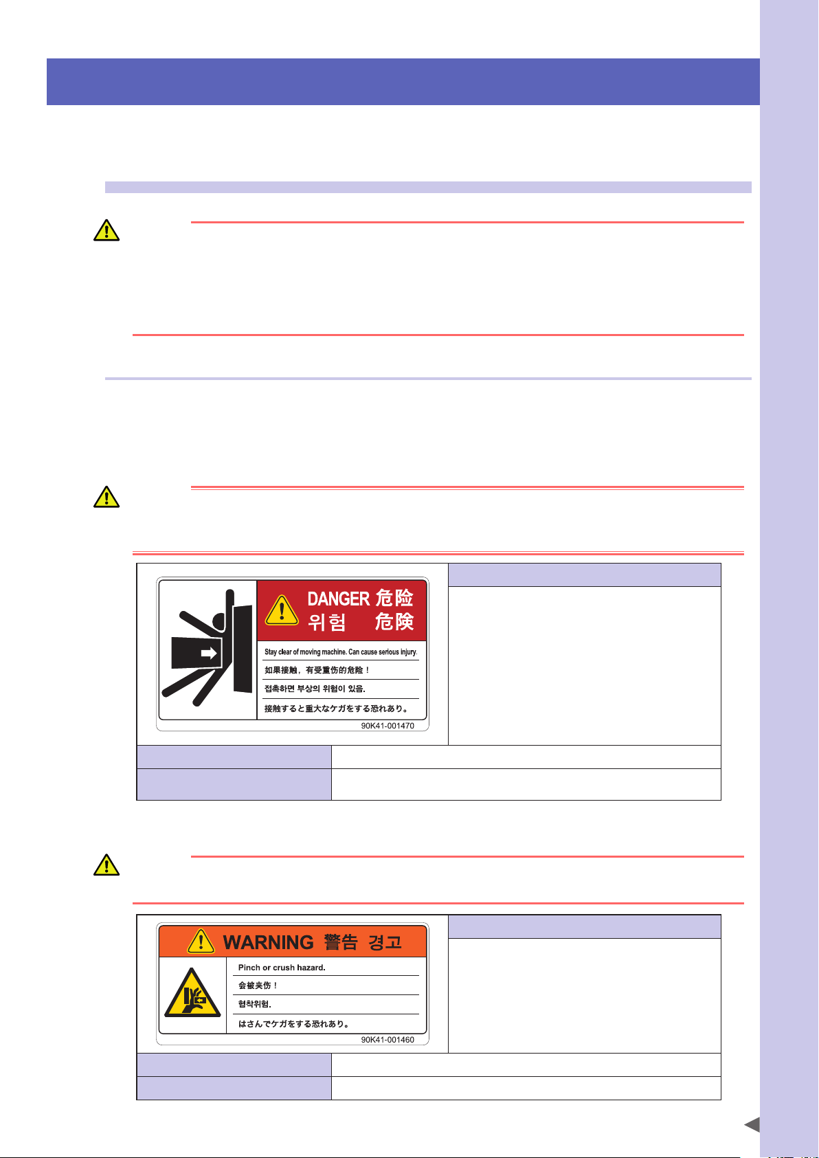
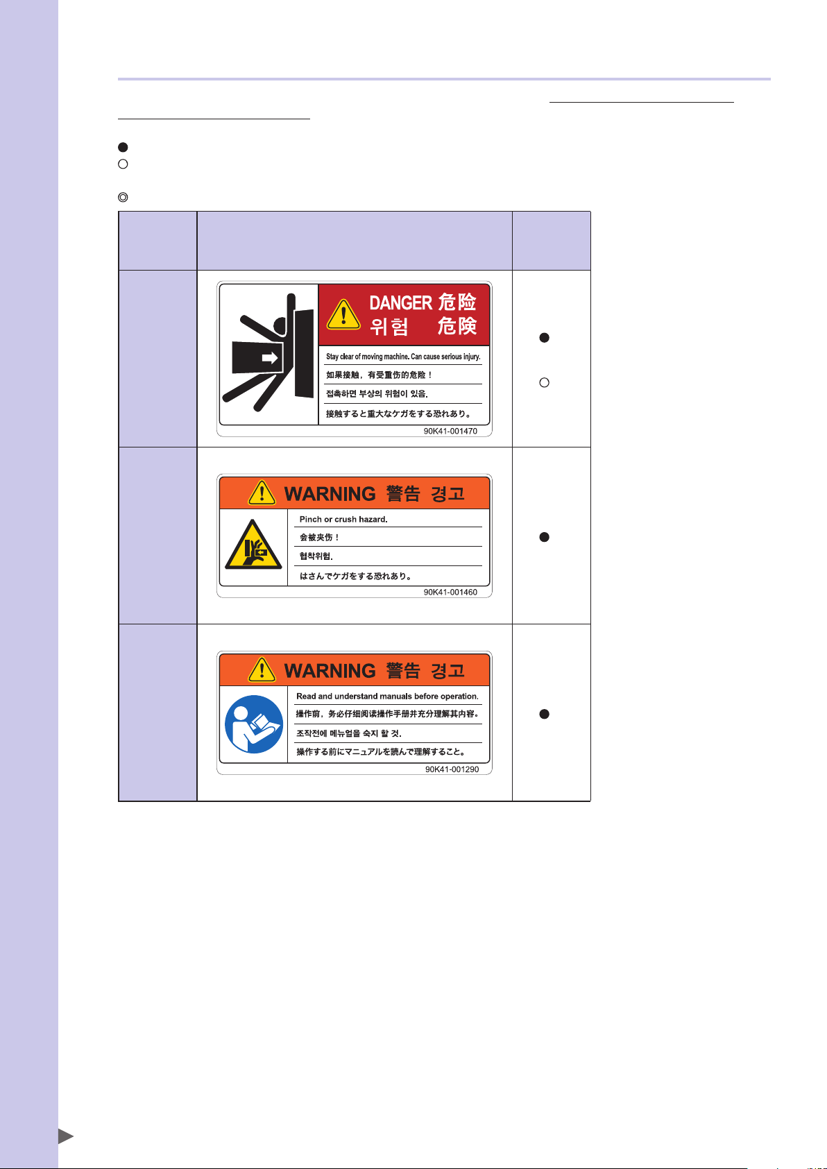
1. Warning label 1 (SCARA robots)
Safety Instructions
DANGER
SERIOUS INJURY MAY RESULT FROM CONTACT WITH A MOVING ROBOT.
• KEEP OUTSIDE OF THE ROBOT SAFETY ENCLOSURE DURING OPERATION.
• PRESS THE EMERGENCY STOP BUTTON BEFORE ENTERING THE SAFETY ENCLOSURE.
• Always install a safety enclosure to keep all persons away
from the robot movement range and prevent injury from
contacting the moving part of the robot.
Install an interlock that triggers emergency stop when the
•
door or gate of the safety enclosure is opened.
• The safety enclosure should be designed so that no one
can enter inside except from the door or gate equipped
with an interlock device.
• Warning label 1 that comes supplied with a robot should
be affixed to an easy-to-see location on the door or gate of
the safety enclosure.
Potential hazard to human body Serious injury may result from contact with a moving robot.
To avoid hazard
• Keep outside of the robot safety enclosure during operation.
• Press the emergency stop button before entering the safety enclosure.
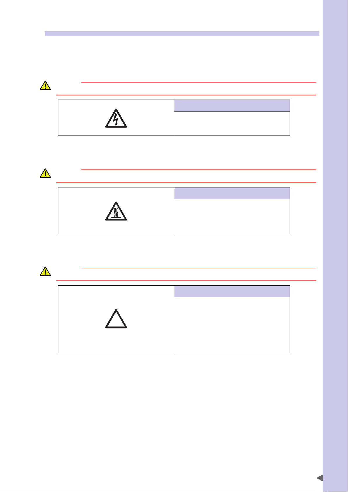
2. Warning label 2 (SCARA robots)
WARNING
MOVING PARTS CAN PINCH OR CRUSH HANDS.
KEEP HANDS AWAY FROM THE MOVABLE PARTS OF THE ROBOT.
Instructions on this label
Instructions on this label
Use caution to prevent hands and fingers from being pinched
or crushed by the movable parts of the robot when
transporting or moving the robot or during teaching.
Potential hazard to human body Moving parts can pinch or crush hands.
To avoid hazard Keep hands away from the movable parts of the robot.
S-3
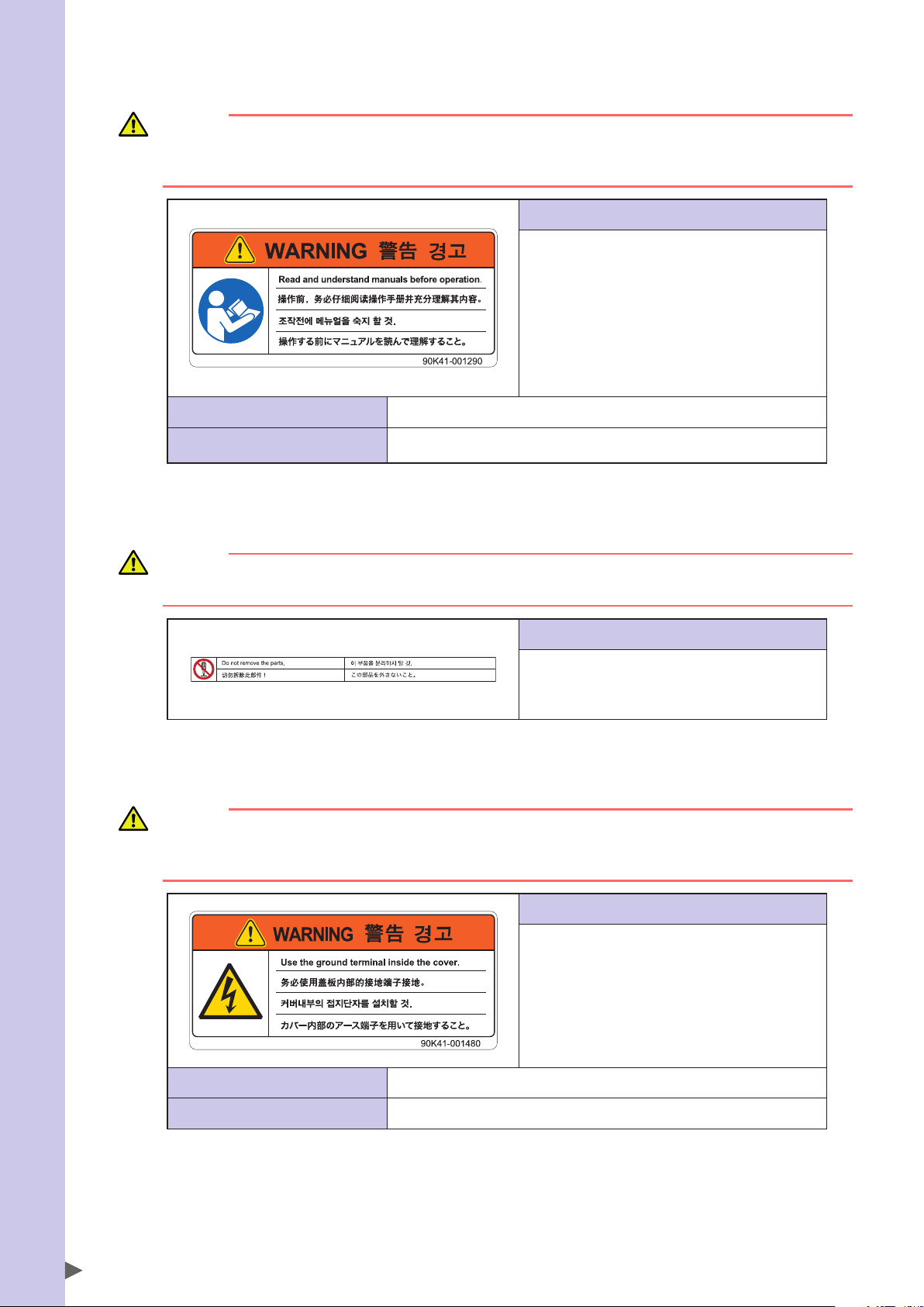
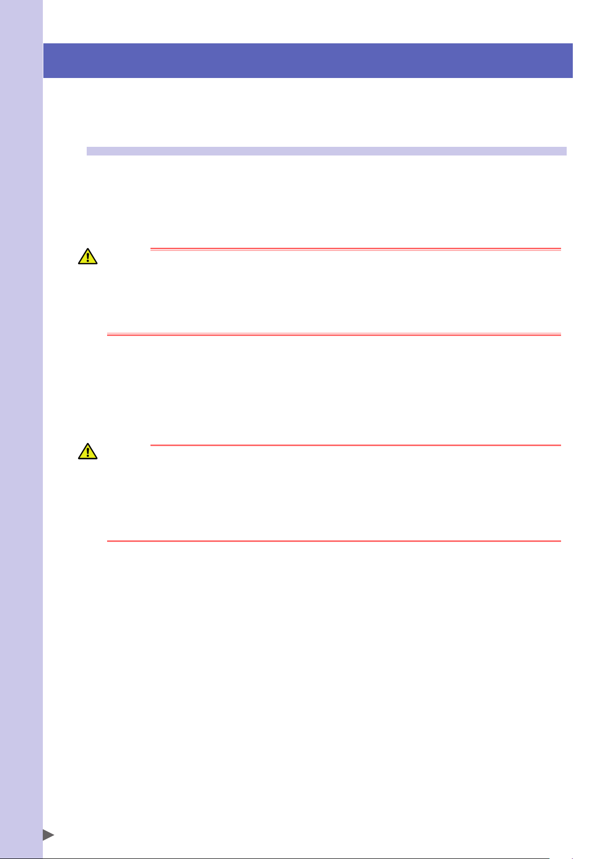
3. Warning label 3 (SCARA robots)
Safety Instructions
WARNING
IMPROPER INSTALLATION OR OPERATION MAY CAUSE SERIOUS INJURY.
BEFORE INSTALLING OR OPERATING THE ROBOT, READ THE MANUAL AND INSTRUCTIONS ON THE WARNING
LABELS AND UNDERSTAND THE CONTENTS.
Instructions on this label
• Be sure to read the warning label and this manual
carefully to make you completely understand the contents
before attempting installation and operation of the robot.
• Before starting the robot operation, even after you have
read through this manual, read again the corresponding
procedures and "Safety instructions" in this manual.
• Never install, adjust, inspect or service the robot in any
manner that does not comply with the instructions in this
manual.
Potential hazard to human body Improper installation or operation may cause serious injury.
To avoid hazard
Before installing or operating the robot, read the manual and instructions on the warning
labels and understand the contents.
4. Warning label 4 (SCARA robots)
CAUTION
Do not remove the parts on which Warning label 4 is attached.
Doing so may damage the ball screw.
5. Warning label 5 (Controller)
WARNING
GROUND THE CONTROLLER TO PREVENT ELECTRICAL SHOCK.
GROUND TERMINAL IS LOCATED INSIDE THIS COVER.
READ THE MANUAL FOR DETAILS.
Potential hazard to human body Electrical shock
Instructions on this label
The Z-axis ball screw will be damaged if the upper end
mechanical stopper on the Z-axis spline is removed or
moved. Never attempt to remove or move it.
Instructions on this label
• High voltage section inside
• To prevent electrical shock, always ground the robot using
the ground terminal located inside the cover.
S-4
To avoid hazard Ground the controller.
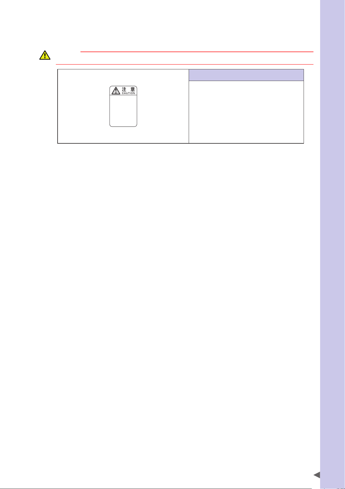
6. "Read instruction manual" label (Controller)*
* This label is attached to the front panel.
CAUTION
Refer to the manual.
取扱説明書参照
READ INSTRUCTION
MANUAL
Safety Instructions
Instructions on this label
This indicates important information that you must know and
is described in the manual.
Before using the controller, be sure to read the manual
thoroughly.
When adding external safety circuits or connecting a power
supply to the controller, read the manual carefully and make
checks before beginning the work.
Connectors have an orientation. Insert each connector in the
correct direction.
S-5
3.1.2 Supplied warning labels
Safety Instructions
Some warning labels are not affixed to robots but included in the packing box. These warning labels should be
affixed to an easy-to-see location.
Warning label is attached to the robot body.
Warning label comes supplied with the robot and should be affixed to an easy-to-see location on the door or gate of the safety
enclosure.
Warning label comes supplied with the robot and should be affixed to an easy-to-see location.
SCARA
robots
1
*
Warning label
1
Warning label
2
Warning label
3
*1: See "Part names" in each SCARA robot manual for label positions.
1
*
1
*
S-6
3.2 Warning symbols
!
Warning symbols shown below are indicated on the robots and controllers to alert the operator to potential hazards. To
use the OMRON robot safely and correctly always follow the instructions and cautions indicated by the symbols.
1. Electrical shock hazard symbol
WARNING
TOUCHING THE TERMINAL BLOCK OR CONNECTOR MAY CAUSE ELECTRICAL SHOCK, SO USE CAUTION.
Instructions by this symbol
This indicates a high voltage is present.
Touching the terminal block or connector may cause
electrical shock.
2. High temperature hazard symbol
WARNING
MOTORS, HEATSINKS, AND REGENERATIVE UNITS BECOME HOT, SO DO NOT TOUCH THEM.
Instructions by this symbol
This indicates the area around this symbol may become very
hot.
Motors, heatsinks, and regenerative units become hot during
and shortly after operation. To avoid burns be careful not to
touch those sections.
Safety Instructions
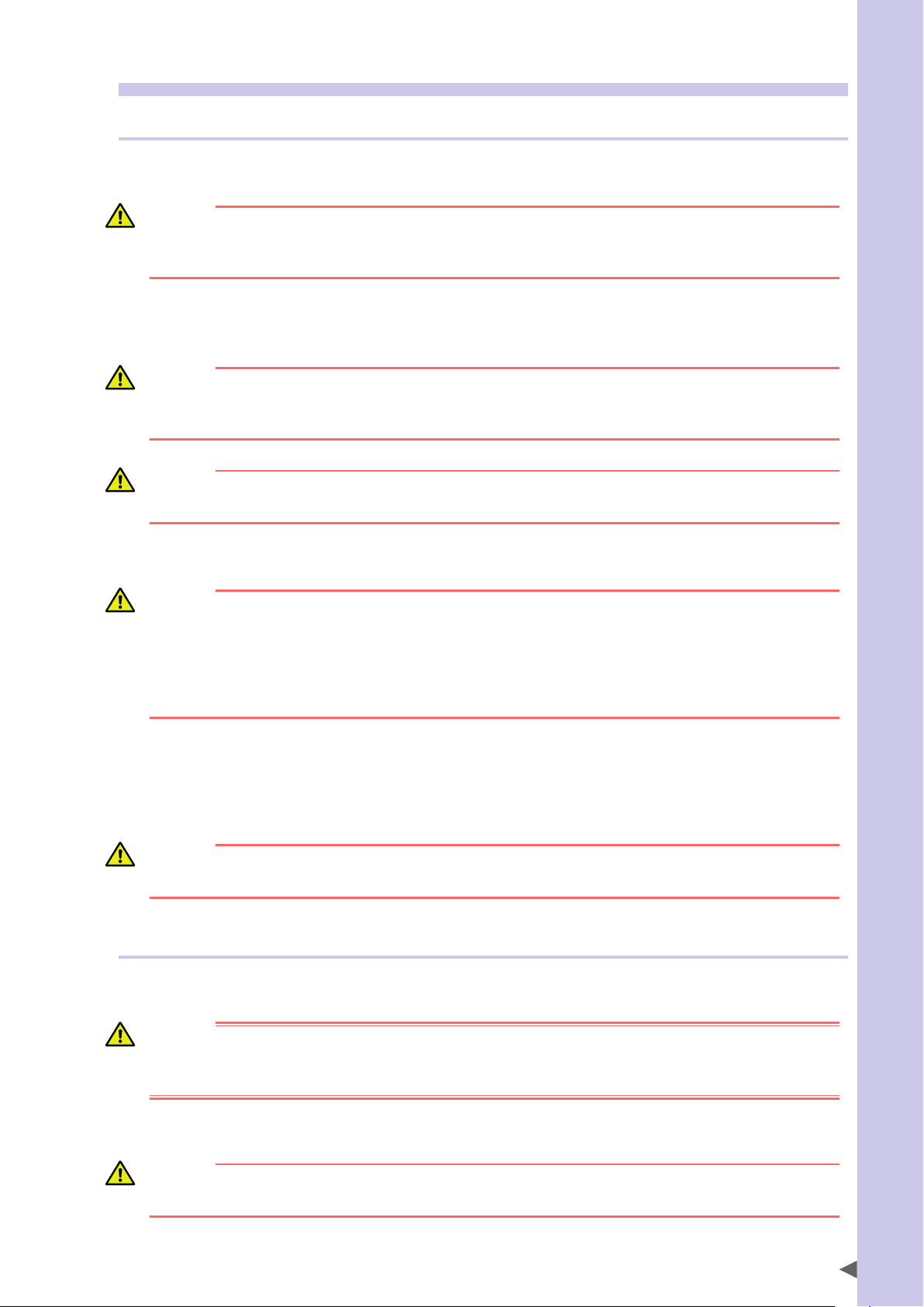
3. Caution symbol
CAUTION
Always read the manual carefully before using the controller.
Instructions by this symbol
This indicates important information that you must know and
is described in the manual.
Before using the controller, be sure to read the manual
thoroughly.
When adding external safety circuits or connecting a power
supply to the controller, read the manual carefully and make
checks before beginning the work.
Connectors must be attached while facing a certain direction,
so insert each connector in the correct direction.
S-7
4. Major precautions for each stage of use
Safety Instructions
This section describes major precautions that must be observed when using robots and controllers. Be sure to carefully
read and comply with all of these precautions even if there is no alert symbol shown.
4.1 Precautions for using robots and controllers
General precautions for using robots and controllers are described below.
1. Applications where robots cannot be used
OMRON robots and robot controllers are designed as general-purpose industrial equipment and cannot be used for the following
applications.
DANGER
OMRON ROBOT CONTROLLERS AND ROBOTS ARE DESIGNED AS GENERAL-PURPOSE INDUSTRIAL EQUIPMENT AND
CANNOT BE USED FOR THE FOLLOWING APPLICATIONS.
• IN MEDICAL EQUIPMENT SYSTEMS WHICH ARE CRITICAL TO HUMAN LIFE
• IN SYSTEMS THAT SIGNIFICANTLY AFFECT SOCIETY AND THE GENERAL PUBLIC
• IN EQUIPMENT INTENDED TO CARRY OR TRANSPORT PEOPLE
• IN ENVIRONMENTS WHICH ARE SUBJECT TO VIBRATION SUCH AS ONBOARD SHIPS AND VEHICLES.
2. Qualification of operators/workers
Operators or persons who handle the robot such as for teaching, programming, movement check, inspection, adjustment, and
repair must receive appropriate training and also have the skills needed to perform the job correctly and safely. They must read the
manual carefully to understand its contents before attempting the robot operation or maintenance.
Tasks related to industrial robots (teaching, programming, movement check, inspection, adjustment, repair, etc.) must be
performed by qualified persons who meet requirements established by local regulations and standards for industrial robots.
WARNING
• THE ROBOT MUST BE OPERATED ONLY BY PERSONS WHO HAVE RECEIVED SAFETY AND OPERATION TRAINING.
OPERATION BY AN UNTRAINED PERSON IS EXTREMELY HAZARDOUS.
• ADJUSTMENT AND MAINTENANCE BY REMOVING A COVER REQUIRE SPECIALIZED TECHNICAL KNOWLEDGE
AND SKILLS, AND MAY ALSO INVOLVE HAZARDS IF ATTEMPTED BY AN UNSKILLED PERSON. THESE TASKS
MUST BE PERFORMED ONLY BY PERSONS WHO HAVE ENOUGH ABILITY AND QUALIFICATIONS IN ACCORDANCE
WITH LOCAL LAWS AND REGULATIONS. FOR DETAILED INFORMATION, PLEASE CONTACT YOUR DISTRIBUTOR
WHERE YOU PURCHASED THE PRODUCT.
S-8
4.2 Design
4.2.1 Precautions for robots
1. Restricting the robot moving speed
WARNING
RESTRICTION ON THE ROBOT MOVING SPEED IS NOT A SAFETY-RELATED FUNCTION.
TO REDUCE THE RISK OF COLLISION BETWEEN THE ROBOT AND WORKERS, THE USER MUST TAKE THE
NECESSARY PROTECTIVE MEASURES SUCH AS ENABLE DEVICES ACCORDING TO RISK ASSESSMENT BY THE USER.
2. Restricting the movement range
See “7.1 Movement range” in “Safety instructions” for details on the robot’s movement range.
WARNING
SOFT LIMIT FUNCTION IS NOT A SAFETY-RELATED FUNCTION INTENDED TO PROTECT THE HUMAN BODY.
TO RESTRICT THE ROBOT MOVEMENT RANGE TO PROTECT THE HUMAN BODY, USE THE MECHANICAL STOPPERS
INSTALLED IN THE ROBOT (OR AVAILABLE AS OPTIONS).
CAUTION
If the robot moving at high speed collides with a mechanical stopper installed in the robot (or available as option), the robot may be
damaged.
3. Provide safety measures for end effector (gripper, etc.)
Safety Instructions
WARNING
• END EFFECTORS MUST BE DESIGNED AND MANUFACTURED SO THAT THEY CAUSE NO HAZARDS (SUCH AS A
LOOSE WORKPIECE OR LOAD) EVEN IF POWER (ELECTRICITY, AIR PRESSURE, ETC.) IS SHUT OFF OR POWER
FLUCTUATIONS OCCUR.
•
IF THE OBJECT GRIPPED BY THE END EFFECTOR MIGHT POSSIBLY FLY OFF OR DROP, THEN PROVIDE
APPROPRIATE SAFETY PROTECTION TAKING INTO ACCOUNT THE OBJECT SIZE, WEIGHT, TEMPERATURE, AND
CHEMICAL PROPERTIES.
4. Provide adequate lighting
Provide enough lighting to ensure safety during work.
5. Install an operation status light
WARNING
INSTALL A SIGNAL LIGHT (SIGNAL TOWER) AT AN EASY-TO-SEE POSITION SO THAT THE OPERATOR WILL BE AWARE
OF THE ROBOT STOP STATUS (TEMPORARILY STOPPED, EMERGENCY STOP, ERROR STOP, ETC.).
4.2.2 Precautions for robot controllers
1. Emergency stop input terminal
DANGER
EACH ROBOT CONTROLLER HAS AN EMERGENCY STOP INPUT TERMINAL TO TRIGGER EMERGENCY STOP. USING
THIS TERMINAL, INSTALL A SAFETY CIRCUIT SO THAT THE SYSTEM INCLUDING THE ROBOT CONTROLLER WILL
WORK SAFELY.
2. Maintain clearance
CAUTION
Do not bundle control lines or communication cables together or in close to the main power supply or power lines. Usually separate
these by at least 100mm. Failure to follow this instruction may cause malfunction due to noise.
S-9
4.3 Moving and installation
Safety Instructions
4.3.1 Precautions for robots
■Installation environment
1. Do not use in strong magnetic fields
WARNING
DO NOT USE THE ROBOT NEAR EQUIPMENT OR IN LOCATIONS THAT GENERATE STRONG MAGNETIC FIELDS. THE
ROBOT MAY BREAK DOWN OR MALFUNCTION IF USED IN SUCH LOCATIONS.
2. Do not use in locations subject to possible electromagnetic interference, etc.
WARNING
DO NOT USE THE ROBOT IN LOCATIONS SUBJECT TO ELECTROMAGNETIC INTERFERENCE, ELECTROSTATIC
DISCHARGE OR RADIO FREQUENCY INTERFERENCE. THE ROBOT MAY MALFUNCTION IF USED IN SUCH LOCATIONS
CREATING HAZARDOUS SITUATIONS.
3. Do not use in locations exposed to flammable gases
WARNING
• OMRON ROBOTS ARE NOT DESIGNED TO BE EXPLOSION-PROOF.
• DO NOT USE THE ROBOTS IN LOCATIONS EXPOSED TO EXPLOSIVE OR INFLAMMABLE GASES, DUST PARTICLES
OR LIQUID. FAILURE TO FOLLOW THIS INSTRUCTION MAY CAUSE SERIOUS ACCIDENTS INVOLVING INJURY OR
DEATH, OR LEAD TO FIRE.
■Moving
1. Use caution to prevent pinching or crushing of hands or fingers
WARNING
MOVING PARTS CAN PINCH OR CRUSH HANDS OR FINGERS.
KEEP HANDS AWAY FROM THE MOVABLE PARTS OF THE ROBOT.
As instructed in Warning label 2, use caution to prevent hands or fingers from being pinched or crushed by movable parts when
transporting or moving the robot. For details on warning labels, see "3. Warning labels" in "Safety instructions."
2. Take safety measures when moving the robot
To ensure safety when moving a SCARA robot with an arm length of 500mm or more, use the eyebolts that come supplied with
the robot.
Refer to the Robot Manual for details.
■Installation
1. Protect electrical wiring and hydraulic/pneumatic hoses
Install a cover or similar item to protect the electrical wiring and hydraulic/pneumatic hoses from possible damage.
■Wiring
1. Protective measures against electrical shock
WARNING
ALWAYS GROUND THE ROBOT TO PREVENT ELECTRICAL SHOCK.
S-10
■Adjustment
1. Adjustment that requires removing a cover
WARNING
ADJUSTMENT BY REMOVING A COVER REQUIRE SPECIALIZED TECHNICAL KNOWLEDGE AND SKILLS, AND MAY
ALSO INVOLVE HAZARDS IF ATEMPTED BY AN UNSKILLED PERSON. THESE TASKS MUST BE PERFORMED ONLY BY
PERSONS WHO HAVE ENOUGH ABILITY AND QUALIFICATIONS IN ACORDANCE WITH LOCAL LAWS AND
REGULATIONS. FOR DETAILED INFORMATION, PLEASE CONTACT YOUR DISTRIBUTOR WHERE YOU PURCHASED
THE PRODUCT.
4.3.2 Precautions for robot controllers
■Installation environment
1. Installation environment
WARNING
OMRON ROBOTS ARE NOT DESIGNED TO BE EXPLOSION-PROOF. DO NOT USE THE ROBOTS AND CONTROLLERS IN
LOCATIONS EXPOSED TO EXPLOSIVE OR INFLAMMABLE GASES, DUST PARTICLES OR LIQUID SUCH AS GASOLINE
AND SOLVENTS. FAILURE TO FOLLOW THIS INSTRUCTION MAY CAUSE SERIOUS ACCIDENTS INVOLVING INJURY
OR DEATH, AND LEAD TO FIRE.
WARNING
• USE THE ROBOT CONTROLLER IN LOCATIONS THAT SUPPORT THE ENVIRONMENTAL CONDITIONS SPECIFIED IN
THIS MANUAL. OPERATION OUTSIDE THE SPECIFIED ENVIRONMENTAL RANGE MAY CAUSE ELECTRICAL SHOCK,
FIRE, MALFUNCTION OR PRODUCT DAMAGE OR DETERIORATION.
• THE ROBOT CONTROLLER AND PROGRAMMING BOX MUST BE INSTALLED AT A LOCATION THAT IS OUTSIDE THE
ROBOT SAFETY ENCLOSURE YET WHERE IT IS EASY TO OPERATE AND VIEW ROBOT MOVEMENT.
• INSTALL THE ROBOT CONTROLLER IN LOCATIONS WITH ENOUGH SPACE TO PERFORM WORK (TEACHING,
INSPECTION, ETC.) SAFELY. LIMITED SPACE NOT ONLY MAKES IT DIFFICULT TO PERFORM WORK BUT CAN ALSO
CAUSE INJURY.
• INSTALL THE ROBOT CONTROLLER IN A STABLE, LEVEL LOCATION AND SECURE IT FIRMLY. AVOID INSTALLING
THE CONTROLLER UPSIDE DOWN OR IN A TILTED POSITION.
• PROVIDE SUFFICIENT CLEARANCE AROUND THE ROBOT CONTROLLER FOR GOOD VENTILATION. INSUFFICIENT
CLEARANCE MAY CAUSE MALFUNCTION, BREAKDOWN OR FIRE.
Safety Instructions
■Installation
To install the robot controller, observe the installation conditions and method described in the manual.
1. Installation
WARNING
SECURELY TIGHTEN THE SCREWS FOR THE L-SHAPED BRACKETS USED TO INSTALL THE ROBOT CONTROLLER. IF
NOT SECURELY TIGHTENED, THE SCREWS MAY COME LOOSE CAUSING THE CONTROLLER TO DROP.
2. Connections
WARNING
• ALWAYS SHUT OFF ALL PHASES OF THE POWER SUPPLY EXTERNALLY BEFORE STARTING INSTALLATION OR
WIRING WORK. FAILURE TO DO THIS MAY CAUSE ELECTRICAL SHOCK OR PRODUCT DAMAGE.
• NEVER DIRECTLY TOUCH CONDUCTIVE SECTIONS AND ELECTRONIC PARTS OTHER THAN THE CONNECTORS,
ROTARY SWITCHES, AND DIP SWITCHES ON THE OUTSIDE PANEL OF THE ROBOT CONTROLLER. TOUCHING
THEM MAY CAUSE ELECTRICAL SHOCK OR BREAKDOWN.
• SECURELY INSTALL EACH CABLE CONNECTOR INTO THE RECEPTACLES OR SOCKETS. POOR CONNECTIONS MAY
CAUSE THE CONTROLLER OR ROBOT TO MALFUNCTION.
S-11
■Wiring
Safety Instructions
1. Connection to robot controller
The controller parameters are preset at the factory before shipping to match the robot model. Check the specified robot and
controller combination, and connect them in the correct combination.
Since the software detects abnormal operation such as motor overloads, the controller parameters must be set correctly to match
the motor type used in the robot connected to the controller.
2. Wiring safety points
WARNING
ALWAYS SHUT OFF ALL PHASES OF THE POWER SUPPLY EXTERNALLY BEFORE STARTING INSTALLATION OR
WIRING WORK. FAILURE TO DO THIS MAY CAUSE ELECTRICAL SHOCK OR PRODUCT DAMAGE.
CAUTION
• Makesurethatnoforeignmattersuchascuttingchipsorwirescrapsgetintotherobotcontroller.Malfunction,breakdownorre
may result if these penetrate inside.
• Do not apply excessive impacts or loads to the connectors when making cable connections. This might bend the connector pins or
damage the internal PC board.
• Whenusingferritecoresfornoiseelimination,besuretotthemontothepowercableasclosetotherobotcontrollerand/orthe
robot as possible, to prevent malfunction caused by noise.
3. Wiring method
WARNING
SECURELY INSTALL THE CONNECTORS INTO THE ROBOT CONTROLLER AND, WHEN WIRING THE CONNECTORS,
MAKE THE CRIMP, PRESS-CONTACT OR SOLDER CONNECTIONS CORRECTLY USING THE TOOL SPECIFIED BY THE
CONNECTOR MANUFACTURER.
CAUTION
When disconnecting the cable from the robot controller, detach by gripping the connector itself and not by tugging on the cable. Loosen
the screws on the connector (if fastened with the screws), and then disconnect the cable. Trying to detach by pulling on the cable itself
may damage the connector or cables, and poor cable contact will cause the controller or robot to malfunction.
4. Precautions for cable routing and installation
CAUTION
• Always store the cables connected to the robot controller in a conduit or clamp them securely in place. If the cables are not stored in
a conduit or properly clamped, excessive play or movement or mistakenly pulling on the cable may damage the connector or cables,
and poor cable contact will cause the controller or robot to malfunction.
• Do not modify the cables and do not place any heavy objects on them. Handle them carefully to avoid damage. Damaged cables may
cause malfunction or electrical shock.
• If the cables connected to the robot controller may possibly become damaged, then protect them with a cover, etc.
• Checkthatthecontrollinesandcommunicationcablesareroutedatagapsufcientlyawayfrommainpowersupplycircuitsand
power lines, etc. Bundling them together with power lines or close to power lines may cause faulty operation due to noise.
5. Protective measures against electrical shock
WARNING
BE SURE TO GROUND THE CONTROLLER USING THE GROUND TERMINAL ON THE POWER TERMINAL BLOCK. POOR
GROUNDING MAY CAUSE ELECTRICAL SHOCK.
S-12
4.4 Safety measures
4.4.1 Safety measures
1. Referring to warning labels and manual
WARNING
• BEFORE STARTING INSTALLATION OR OPERATION OF THE ROBOT, BE SURE TO READ THE WARNING LABELS
AND THIS MANUAL, AND COMPLY WITH THE INSTRUCTIONS.
• NEVER ATTEMPT ANY REPAIR, PARTS REPLACEMENT AND MODIFICATION UNLESS DESCRIBED IN THIS MANUAL.
THESE TASKS REQUIRE SPECIALIZED TECHNICAL KNOWLEDGE AND SKILLS AND MAY ALSO INVOLVE
HAZARDS. PLEASE CONTACT YOUR DISTRIBUTOR FOR ADVICE.
NOTE
For details on warning labels, see "3. Warning labels" in "Safety instructions."
2. Draw up "work instructions" and make the operators/workers understand them
WARNING
DECIDE ON "WORK INSTRUCTIONS" IN CASES WHERE PERSONNEL MUST WORK WITHIN THE ROBOT SAFETY
ENCLOSURE TO PERFORM STARTUP OR MAINTENANCE WORK. MAKE SURE THE WORKERS COMPLETELY
UNDERSTAND THESE "WORK INSTRUCTIONS".
Decide on "work instructions" for the following items in cases where personnel must work within the robot safety enclosure to
perform teaching, maintenance or inspection tasks. Make sure the workers completely understand these "work instructions".
1. Robot operating procedures needed for tasks such as startup procedures and handling switches
2. Robot speeds used during tasks such as teaching
3. Methods for workers to signal each other when two or more workers perform tasks
4. Steps that the worker should take when a problem or emergency occurs
5. Steps to take after the robot has come to a stop when the emergency stop device was triggered, including checks for cancelling
the problem or error state and safety checks in order to restart the robot.
6. In cases other than above, the following actions should be taken as needed to prevent hazardous situations due to sudden or
unexpected robot operation or faulty robot operation as listed below.
• Place a display sign on the operator panel
• Ensure the safety of workers performing tasks within the robot safety enclosure
• Clearly specify position and posture during work
Specify a position and posture where worker can constantly check robot movements and immediately move to avoid
trouble if an error/problem occurs
• Take noise prevention measures
• Use methods for signaling operators of related equipment
• Use methods to decide that an error has occurred and identify the type of error
Implement the "work instructions" according to the type of robot, installation location, and type of work task.
When drawing up the "work instructions", make an effort to include opinions from the workers involved, equipment manufacturer
technicians, and workplace safety consultants, etc.
Safety Instructions
3. Take safety measures
DANGER
• NEVER ENTER THE ROBOT MOVEMENT RANGE WHILE THE ROBOT IS OPERATING OR THE MAIN POWER IS
TURNED ON. FAILURE TO FOLLOW THIS WARNING MAY CAUSE SERIOUS ACCIDENTS INVOLVING INJURY OR
DEATH. INSTALL A SAFETY ENCLOSURE OR A GATE INTERLOCK WITH AN AREA SENSOR TO KEEP ALL PERSONS
AWAY FROM THE ROBOT MOVEMENT RANGE.
• WHEN IT IS NECESSARY TO OPERATE THE ROBOT WHILE YOU ARE WITHIN THE ROBOT MOVEMENT RANGE
SUCH AS FOR TEACHING OR MAINTENANCE/INSPECTION TASKS, ALWAYS CARRY THE PROGRAMMING BOX
WITH YOU SO THAT YOU CAN IMMEDIATELY STOP THE ROBOT OPERATION IN CASE OF AN ABNORMAL OR
HAZARDOUS CONDITION. INSTALL AN ENABLE DEVICE IN THE EXTERNAL SAFETY CIRCUIT AS NEEDED. ALSO
SET THE ROBOT MOVING SPEED TO 3% OR LESS. FAILURE TO FOLLOW THESE INSTRUCTIONS MAY CAUSE
SERIOUS ACCIDENTS INVOLVING INJURY OR DEATH.
See “7.1 Movement range” in “Safety instructions” for details on the robot’s movement range.
S-13

Safety Instructions
WARNING
• DURING STARTUP OR MAINTENANCE TASKS, DISPLAY A SIGN "WORK IN PROGRESS" ON THE PROGRAMMING
BOX AND OPERATION PANEL IN ORDER TO PREVENT ANYONE OTHER THAN THE PERSON FOR THAT TASK FROM
MISTAKENLY OPERATING THE START OR SELECTOR SWITCH. IF NEEDED, TAKE OTHER MEASURES SUCH AS
LOCKING THE COVER ON THE OPERATION PANEL.
• ALWAYS CONNECT THE ROBOT AND ROBOT CONTROLLER IN THE CORRECT COMBINATION. USING THEM IN AN
INCORRECT COMBINATION MAY CAUSE FIRE OR BREAKDOWN.
4. Install system
When configuring an automated system using a robot, hazardous situations are more likely to occur from the automated system
than the robot itself. So the system manufacturer should install the necessary safety measures required for the individual system.
The system manufacturer should provide a proper manual for safe, correct operation and servicing of the system.
WARNING
TO CHECK THE ROBOT CONTROLLER OPERATING STATUS, REFER TO THIS MANUAL AND TO RELATED MANUALS.
DESIGN AND INSTALL THE SYSTEM INCLUDING THE ROBOT CONTROLLER SO THAT IT WILL ALWAYS WORK
SAFELY.
5. Precautions for operation
WARNING
• DO NOT TOUCH ANY ELECTRICAL TERMINAL. DIRECTLY TOUCHING THESE TERMINALS MAY CAUSE
ELECTRICAL SHOCK, EQUIPMENT DAMAGE, AND MALFUNCTION.
• DO NOT TOUCH OR OPERATE THE ROBOT CONTROLLER OR PROGRAMMING BOX WITH WET HANDS. TOUCHING
OR OPERATING THEM WITH WET HANDS MAY RESULT IN ELECTRICAL SHOCK OR BREAKDOWN.
6. Do not disassemble and modify
WARNING
NEVER DISASSEMBLE AND MODIFY ANY PART IN THE ROBOT, CONTROLLER, AND PROGRAMMING BOX. DO NOT
OPEN ANY COVER. DOING SO MAY CAUSE ELECTRICAL SHOCK, BREAKDOWN, MALFUNCTION, INJURY, OR FIRE.
4.4.2 Installing a safety enclosure
Be sure to install a safety enclosure to keep anyone from entering within the movement range of the robot. The safety
enclosure will prevent the operator and other persons from coming in contact with moving parts of the robot and
suffering injury.
See “7.1 Movement range” in “Safety instructions” for details on the robot’s movement range.
DANGER
SERIOUS INJURY MAY RESULT FROM CONTACT WITH A MOVING ROBOT.
• KEEP OUTSIDE OF THE ROBOT SAFETY ENCLOSURE DURING OPERATION.
• PRESS THE EMERGENCY STOP BUTTON BEFORE ENTERING THE SAFETY ENCLOSURE.
WARNING
• INSTALL AN INTERLOCK THAT TRIGGERS EMERGENCY STOP WHEN THE DOOR OR GATE OF THE SAFETY
ENCLOSURE IS OPENED.
• THE SAFETY ENCLOSURE SHOULD BE DESIGNED SO THAT NO ONE CAN ENTER INSIDE EXCEPT FROM THE DOOR
OR GATE EQUIPPED WITH AN INTERLOCK DEVICE.
• WARNING LABEL 1 (SEE "3. WARNING LABELS" IN "SAFETY INSTRUCTIONS") THAT COMES SUPPLIED WITH A
ROBOT SHOULD BE AFFIXED TO AN EASY-TO-SEE LOCATION ON THE DOOR OR GATE OF THE SAFETY
ENCLOSURE.
S-14
4.5 Operation
When operating a robot, ignoring safety measures and checks may lead to serious accidents. Always take the following
safety measures and checks to ensure safe operation.
DANGER
CHECK THE FOLLOWING POINTS BEFORE STARTING ROBOT OPERATION.
• NO ONE IS WITHIN THE ROBOT SAFETY ENCLOSURE.
• THE PROGRAMMING UNIT IS IN THE SPECIFIED LOCATION.
• THE ROBOT AND PERIPHERAL EQUIPMENT ARE IN GOOD CONDITION.
4.5.1 Trial operation
After installing, adjusting, inspecting, maintaining or repairing the robot, perform trial operation using the following
procedures.
1. If a safety enclosure has not yet been provided right after installing the robot:
Then rope off or chain off the movement range around the robot in place of the safety enclosure and observe the following points.
See “7.1 Movement range” in “Safety instructions” for details on the robot’s movement range.
DANGER
PLACE A "ROBOT IS MOVING - KEEP AWAY!" SIGN TO KEEP THE OPERATOR OR OTHER PERSONNEL FROM ENTERING
WITHIN THE MOVEMENT RANGE OF THE ROBOT.
Safety Instructions
WARNING
• USE STURDY, STABLE POSTS WHICH WILL NOT FALL OVER EASILY.
• THE ROPE OR CHAIN SHOULD BE EASILY VISIBLE TO EVERYONE AROUND THE ROBOT.
2. Check the following points before turning on the controller.
• Is the robot securely and correctly installed?
• Are the electrical connections to the robot wired correctly?
• Are items such as air pressure correctly supplied?
• Is the robot correctly connected to peripheral equipment?
• Have safety measures (safety enclosure, etc.) been taken?
• Does the installation environment meet the specified standards?
3. After the controller is turned on, check the following points from outside the safety enclosure.
• Does the robot start, stop and enter the selected operation mode as intended?
• Does each axis move as intended within the soft limits?
• Does the end effector move as intended?
• Are the correct signals being sent to the end effector and peripheral equipment?
• Does emergency stop function?
• Are teaching and playback functions normal?
• Are the safety enclosure and interlocks functioning as intended?
S-15
4. Working inside safety enclosures
Safety Instructions
Before starting work within the safety enclosure, always confirm from outside the enclosure that each protective function is
operating correctly (see the previous section 2.3).
DANGER
NEVER ENTER WITHIN THE MOVEMENT RANGE WHILE WITHIN THE SAFETY ENCLOSURE.
See “7.1 Movement range” in “Safety instructions” for details on the robot’s movement range.
WARNING
WHEN WORK IS REQUIRED WITHIN THE SAFETY ENCLOSURE, PLACE A SIGN "WORK IN PROGRESS" IN ORDER TO
KEEP OTHER PERSONS FROM OPERATING THE CONTROLLER SWITCH OR OPERATION PANEL.
WARNING
WHEN WORK WITHIN THE SAFETY ENCLOSURE IS REQUIRED, ALWAYS TURN OFF THE CONTROLLER POWER
EXCEPT FOR THE FOLLOWING CASES:
Exception
Work with power turned on, but robot in emergency stop
Origin position setting SCARA robots
Standard coordinate setting SCARA robots
Soft limit settings SCARA robots
Follow the precautions and procedure described in "2. Adjusting the origin"
in Chapter 3.
Follow the precautions and procedure described in "4. Setting the standard
coordinates" in Chapter 3.
Follow the precautions and procedure described in "3. Setting the soft
limits" in Chapter 3.
Work with power turned on
Teaching SCARA robots Refer to "5. Teaching within safety enclosure" described below.
5. Teaching within the safety enclosure
When performing teaching within the safety enclosure, check or perform the following points from outside the safety enclosure.
DANGER
NEVER ENTER WITHIN THE MOVEMENT RANGE WHILE WITHIN THE SAFETY ENCLOSURE.
See “7.1 Movement range” in “Safety instructions” for details on the robot’s movement range.
WARNING
• MAKE A VISUAL CHECK TO ENSURE THAT NO HAZARDS ARE PRESENT WITHIN THE SAFETY ENCLOSURE.
• CHECK THAT THE PROGRAMMING BOX OR HANDY TERMINAL OPERATES CORRECTLY.
• CHECK THAT NO FAILURES ARE FOUND IN THE ROBOT.
• CHECK THAT EMERGENCY STOP WORKS CORRECTLY.
• SELECT TEACHING MODE AND DISABLE AUTOMATIC OPERATION.
S-16
4.5.2 Automatic operation
Check the following points when operating the robot in AUTO mode. Observe the instructions below in cases where an
error occurs during automatic operation. Automatic operation described here includes all operations in AUTO mode.
1. Checkpoints before starting automatic operation
Check the following points before starting automatic operation
DANGER
• CHECK THAT NO ONE IS WITHIN THE SAFETY ENCLOSURE.
• CHECK THE SAFETY ENCLOSURE IS SECURELY INSTALLED WITH INTERLOCKS FUNCTIONAL.
WARNING
• CHECK THAT THE PROGRAMMING BOX / HANDY TERMINAL AND TOOLS ARE IN THEIR SPECIFIED LOCATIONS.
• CHECK THAT THE SIGNAL TOWER LAMPS OR OTHER ALARM DISPLAYS INSTALLED FOR THE SYSTEM ARE NOT
LIT OR FLASHING, INDICATING NO ERROR IS OCCURRING ON THE ROBOT AND PERIPHERAL DEVICES.
2. During automatic operation and when errors occur
After automatic operation starts, check the operation status and the signal tower to ensure that the robot is in automatic operation.
DANGER
NEVER ENTER THE SAFETY ENCLOSURE DURING AUTOMATIC OPERATION.
WARNING
IF AN ERROR OCCURS IN THE ROBOT OR PERIPHERAL EQUIPMENT, OBSERVE THE FOLLOWING PROCEDURE
BEFORE ENTERING THE SAFETY ENCLOSURE.
1) PRESS THE EMERGENCY STOP BUTTON TO SET THE ROBOT TO EMERGENCY STOP.
2) PLACE A SIGN ON THE START SWITCH, INDICATING THAT THE ROBOT IS BEING INSPECTED IN ORDER TO KEEP
OTHER PERSONS FROM RESTARTING THE ROBOT.
Safety Instructions
4.5.3 Precautions during operation
1. When the robot is damaged or an abnormal condition occurs
WARNING
• IF UNUSUAL ODORS, NOISE OR SMOKE OCCUR DURING OPERATION, IMMEDIATELY TURN OFF POWER TO
PREVENT POSSIBLE ELECTRICAL SHOCK, FIRE OR BREAKDOWN. STOP USING THE ROBOT AND CONTACT YOUR
DISTRIBUTOR.
• IF ANY OF THE FOLLOWING DAMAGE OR ABNORMAL CONDITIONS OCCURS THE ROBOT, THEN CONTINUING TO
OPERATE THE ROBOT IS DANGEROUS. IMMEDIATELY STOP USING THE ROBOT AND CONTACT YOUR
DISTRIBUTOR.
Damage or abnormal condition Type of danger
Damage to machine harness or robot cable Electrical shock, robot malfunction
Damage to robot exterior Damaged parts fly off during robot operation
Abnormal robot operation (position deviation, vibration, etc.) Robot malfunction
Z-axis (vertical axis) or brake malfunction Loads fall off
2. High temperature hazard
WARNING
• DO NOT TOUCH THE ROBOT CONTROLLER AND ROBOT DURING OPERATION. THE ROBOT CONTROLLER AND
ROBOT BODY ARE VERY HOT DURING OPERATION, SO BURNS MAY OCCUR IF THESE SECTIONS ARE TOUCHED.
• THE MOTOR AND SPEED REDUCTION GEAR CASING ARE VERY HOT SHORTLY AFTER OPERATION, SO BURNS MAY
OCCUR IF THESE ARE TOUCHED. BEFORE TOUCHING THOSE PARTS FOR INSPECTIONS OR SERVICING, TURN OFF
THE CONTROLLER, WAIT FOR A WHILE AND CHECK THAT THEIR TEMPERATURE HAS COOLED.
S-17
3. Use caution when releasing the Z-axis (vertical axis) brake
Safety Instructions
WARNING
THE VERTICAL AXIS WILL SLIDE DOWNWARD WHEN THE BRAKE IS RELEASED, CAUSING A HAZARDOUS
SITUATION. TAKE ADEQUATE SAFETY MEASURES IN CONSIDERATION BY TAKING THE WEIGHT AND SHAPE INTO
ACCOUNT.
• BEFORE RELEASING THE BRAKE AFTER PRESSING THE EMERGENCY STOP BUTTON, PLACE A SUPPORT UNDER
THE VERTICAL AXIS SO THAT IT WILL NOT SLIDE DOWN.
• BE CAREFUL NOT TO LET YOUR BODY GET CAUGHT BETWEEN THE VERTICAL AXIS AND THE INSTALLATION
BASE WHEN PERFORMING TASKS (DIRECT TEACHING, ETC.) WITH THE BRAKE RELEASED.
4. Be careful of Z-axis movement when the controller is turned off or emergency stop is triggered
(air-driven Z-axis)
WARNING
THE Z-AXIS STARTS MOVING UPWARD WHEN POWER TO THE CONTROLLER OR PLC IS TURNED OFF, THE PROGRAM
IS RESET, EMERGENCY STOP IS TRIGGERED, OR AIR IS SUPPLIED TO THE SOLENOID VALVE FOR THE Z-AXIS AIR
CYLINDER.
• DO NOT LET HANDS OR FINGERS GET CAUGHT AND SQUEEZED BY ROBOT PARTS MOVING ALONG THE Z-AXIS.
• KEEP THE USUAL ROBOT POSITION IN MIND SO AS TO PREVENT THE Z-AXIS FROM HANGING UP OR BINDING ON
OBSTACLES DURING RAISING OF THE Z-AXIS EXCEPT IN CASE OF EMERGENCY STOP.
5. Take protective measures when the Z-axis interferes with peripheral equipment (air-driven Z-axis)
WARNING
WHEN THE Z-AXIS COMES TO A STOP DUE TO OBSTRUCTION FROM PERIPHERAL EQUIPMENT, THE Z-AXIS MAY
MOVE SUDDENLY AFTER THE OBSTRUCTION IS REMOVED, CAUSING INJURY SUCH AS PINCHED OR CRUSHED
HANDS.
• TURN OFF THE CONTROLLER AND REDUCE THE AIR PRESSURE BEFORE ATTEMPTING TO REMOVE THE
OBSTRUCTION.
• BEFORE REDUCING THE AIR PRESSURE, PLACE A SUPPORT UNDER THE Z-AXIS BECAUSE THE Z-AXIS WILL DROP
UNDER ITS OWN WEIGHT.
6. Be careful of Z-axis movement when air supply is stopped (air-driven Z-axis)
WARNING
THE Z-AXIS WILL SLIDE DOWNWARD WHEN THE AIR PRESSURE TO THE Z-AXIS AIR CYLINDER SOLENOID VALVE IS
REDUCED, CREATING A HAZARDOUS SITUATION.
TURN OFF THE CONTROLLER AND PLACE A SUPPORT UNDER THE Z-AXIS BEFORE CUTTING OFF THE AIR SUPPLY.
7. Make correct parameter settings
CAUTION
Therobotmustbeoperatedwiththecorrecttolerablemomentofinertiaandaccelerationcoefcientsthatmatchthemanipulatortip
mass and moment of inertia. Failure to follow this instruction will lead to a premature end to the drive unit service life, damage to robot
parts, or cause residual vibration during positioning.
8. If the X-axis, Y-axis or R-axis rotation angle is small
CAUTION
If the X-axis, Y-axis or R-axis rotation angle is set smaller than 5 degrees, then it will always move within the same position. This
restrictedpositionmakesitdifcultforanoillmtoformonthejointsupportbearing,andsomaypossiblydamagethebearing.Inthis
type of operation, add a range of motion so that the joint moves through 90 degrees or more, about 5 times a day.
S-18

4.6 Inspection and maintenance
Always perform daily and periodic inspections and make a pre-operation check to ensure there are no problems with
the robot and related equipment. If a problem or abnormality is found, then promptly repair it or take other measures as
necessary.
Keep a record of periodic inspections or repairs and store this record for at least 3 years.
4.6.1 Before inspection and maintenance work
1. Do not attempt any work or operation unless described in this manual.
Never attempt any work or operation unless described in this manual.
If an abnormal condition occurs, please be sure to contact your distributor. Our service personnel will take appropriate action.
WARNING
NEVER ATTEMPT INSPECTION, MAINTENANCE, REPAIR, AND PART REPLACEMENT UNLESS DESCRIBED IN THIS
MANUAL. THESE TASKS REQUIRE SPECIALIZED TECHNICAL KNOWLEDGE AND SKILLS AND MAY ALSO INVOLVE
HAZARDS. PLEASE BE SURE TO CONTACT YOUR DISTRIBUTOR FOR ADVICE.
2. Precautions during repair and parts replacement
WARNING
WHEN IT IS NECESSARY TO REPAIR OR REPLACE PARTS OF THE ROBOT OR CONTROLLER, PLEASE BE SURE TO
CONTACT YOUR DISTRIBUTOR AND FOLLOW THE INSTRUCTIONS THEY PROVIDE. INSPECTION AND MAINTENANCE
OF THE ROBOT OR CONTROLLER BY AN UNSKILLED, UNTRAINED PERSON IS EXTREMELY HAZARDOUS.
Safety Instructions
Adjustment, maintenance and parts replacement require specialized technical knowledge and skills, and also may involve hazards.
These tasks must be performed only by persons who have enough ability and qualifications required by local laws and regulations.
WARNING
ADJUSTMENT AND MAINTENANCE BY REMOVING A COVER REQUIRE SPECIALIZED TECHNICAL KNOWLEDGE AND
SKILLS, AND MAY ALSO INVOLVE HAZARDS IF ATTEMPTED BY AN UNSKILLED PERSON. FOR DETAILED
INFORMATION, PLEASE CONTACT YOUR DISTRIBUTOR WHERE YOU PURCHASED THE PRODUCT.
3. Shut off all phases of power supply
WARNING
ALWAYS SHUT OFF ALL PHASES OF THE POWER SUPPLY EXTERNALLY BEFORE CLEANING THE ROBOT AND
CONTROLLER OR SECURELY TIGHTENING THE TERMINAL SCREWS ETC. FAILURE TO DO THIS MAY CAUSE
ELECTRICAL SHOCK OR PRODUCT DAMAGE OR MALFUNCTION.
4. Allow a waiting time after power is shut off (Allow time for temperature and voltage to drop)
WARNING
• WHEN PERFORMING MAINTENANCE OR INSPECTION OF THE ROBOT CONTROLLER UNDER YOUR DISTRIBUTOR'S
INSTRUCTIONS, WAIT AT LEAST THE TIME SPECIFIED FOR EACH CONTROLLER AFTER TURNING THE POWER OFF.
SOME COMPONENTS IN THE ROBOT CONTROLLER ARE VERY HOT OR STILL RETAIN A HIGH VOLTAGE SHORTLY
AFTER OPERATION, SO BURNS OR ELECTRICAL SHOCK MAY OCCUR IF THOSE PARTS ARE TOUCHED.
• THE MOTOR AND SPEED REDUCTION GEAR CASING ARE VERY HOT SHORTLY AFTER OPERATION, SO BURNS MAY
OCCUR IF THEY ARE TOUCHED. BEFORE TOUCHING THOSE PARTS FOR INSPECTIONS OR SERVICING, TURN OFF
THE CONTROLLER, WAIT FOR A WHILE AND CHECK THAT THE TEMPERATURE HAS COOLED.
5. Precautions during inspection of controller
WARNING
• WHEN YOU NEED TO TOUCH THE TERMINALS OR CONNECTORS ON THE OUTSIDE OF THE CONTROLLER DURING
INSPECTION, ALWAYS FIRST TURN OFF THE CONTROLLER POWER SWITCH AND ALSO THE POWER SOURCE IN
ORDER TO PREVENT POSSIBLE ELECTRICAL SHOCK.
• DO NOT DISASSEMBLE THE CONTROLLER. NEVER TOUCH ANY INTERNAL PARTS OF THE CONTROLLER. DOING
SO MAY CAUSE BREAKDOWN, MALFUNCTION, INJURY, OR FIRE.
S-19
4.6.2 Precautions during service work
Safety Instructions
1. Be careful when removing the Z-axis motor (SCARA robots)
WARNING
THE Z-AXIS WILL SLIDE DOWNWARD WHEN THE Z-AXIS MOTOR IS REMOVED, CAUSING A HAZARDOUS SITUATION.
• TURN OFF THE CONTROLLER AND PLACE A SUPPORT UNDER THE Z-AXIS BEFORE REMOVING THE Z-AXIS
MOTOR.
• BE CAREFUL NOT TO LET YOUR BODY GET CAUGHT BY THE DRIVING UNIT OF THE Z-AXIS OR BETWEEN THE
Z-AXIS DRIVE UNIT AND THE INSTALLATION BASE.
2. Do not remove the Z-axis upper limit mechanical stopper
CAUTION
Warning label 4 is attached to each SCARA robot. (For details on warning labels, see "3. Warning labels" in "Safety instructions.")
Removing the upper limit mechanical stopper installed to the Z-axis spline or shifting its position will damage the Z-axis ball screw.
Never attempt to remove it.
3. Use caution when handling a robot that contains powerful magnets
WARNING
POWERFUL MAGNETS ARE INSTALLED INSIDE THE ROBOT. DO NOT DISASSEMBLE THE ROBOT SINCE THIS MAY
CAUSE INJURY. DEVICES THAT MAY MALFUNCTION DUE TO MAGNETIC FIELDS MUST BE KEPT AWAY FROM THIS
ROBOT.
See "6. Cautions regarding strong magnetic fields" in "Safety instructions" for detailed information on strong magnetic fields.
4. Use the following caution items when disassembling or replacing the pneumatic equipment.
WARNING
AIR OR PARTS MAY FLY OUTWARD IF PNEUMATIC EQUIPMENT IS DISASSEMBLED OR PARTS REPLACED WHILE AIR
IS STILL SUPPLIED.
• DO SERVICE WORK AFTER TURNING OFF THE CONTROLLER, REDUCING THE AIR PRESSURE, AND EXHAUSTING
THE RESIDUAL AIR FROM THE PNEUMATIC EQUIPMENT.
• BEFORE REDUCING THE AIR PRESSURE, PLACE A SUPPORT STAND UNDER THE Z-AXIS SINCE IT WILL DROP
UNDER ITS OWN WEIGHT.
5. Use caution to avoid contact with the controller cooling fan
WARNING
• TOUCHING THE ROTATING FAN MAY CAUSE INJURY.
• IF REMOVING THE FAN COVER, FIRST TURN OFF THE CONTROLLER AND MAKE SURE THE FAN HAS STOPPED.
6. Precautions for robot controllers
CAUTION
• Back up the robot controller internal data on an external storage device. The robot controller internal data
may be lost or deleted for unexpected reasons. Always make a backup of this data.
• Do not use thinner, benzene, or alcohol to wipe off the surface of the programming box. The surface sheet may be damaged or
printed letters or marks erased. Use a soft, dry cloth and gently wipe the surface.
• Do not use a hard or pointed object to press the keys on the programming box. Malfunction or breakdown may result if the keys are
damaged.Useyourngerstooperatethekeys.
• DonotinsertanySDmemorycardotherthanspeciedintotheSDmemorycardslotintheprogrammingbox.Malfunctionor
breakdown may result if the wrong memory card is inserted.
(programs, point data, etc.)
S-20
4.7 Disposal
When disposing of robots and related items, handle them carefully as industrial wastes. Use the correct disposal method
in compliance with your local regulations, or entrust disposal to a licensed industrial waste disposal company.
1. Disposal of lithium batteries
When disposing of lithium batteries, use the correct disposal method in compliance with your local regulations, or entrust disposal
to a licensed industrial waste disposal company. We do not collect and dispose of the used batteries.
2. Disposal of packing boxes and materials
When disposing of packing boxes and materials, use the correct disposal method in compliance with your local regulations. We do
not collect and dispose of the used packing boxes and materials.
3. Strong magnet
WARNING
STRONG MAGNETS ARE INSTALLED IN THE ROBOT. BE CAREFUL WHEN DISPOSING OF THE ROBOT.
See "6. Cautions regarding strong magnetic fields" in "Safety instructions" for detailed information on strong magnetic fields.
Safety Instructions
S-21

5.
Emergency action when a person is caught by robot
Safety Instructions
If a person should get caught between the robot and a mechanical part such as the installation base, then release the
axis.
■Emergency action
Release the axis while referring to the following section in the manual for the robot controller.
Controller Refer to:
YRC Section 1, "Freeing a person caught by the robot" in Chapter 1
YRCX
NOTE
Make a printout of the relevant page in the manual and post it a conspicuous location near the controller.
Section 1, "Emergency action when a person is caught by robot" in
Chapter 1
6. Cautions regarding strong magnetic fields
Some OMRON robots contain parts generating strong magnetic fields which may cause bodily injury, death, or device
malfunction. Always comply with the following instructions.
• Persons wearing ID cards, purses, or wristwatches must keep away from the robot.
• Do not bring tools close to the magnet inside the robot.
S-22
 Loading...