

Page 1
Quattro
650H/650HS/800H/800HS
User’s Guide
I597-E-05
Page 2

Copyright Notice
The information contained herein is the property of Omron Adept Technologies, Inc., and shall not be
reproduced in whole or in part without prior written approval of Omron Adept Technologies, Inc. The
information herein is subject to change without notice and should not be construed as a commitment by
Omron Adept Technologies, Inc. The documentation is periodically reviewed and revised.
Omron Adept Technologies, Inc., assumes no responsibility for any errors or omissions in the documentation. Critical evaluation of the documentation by the user is welcomed. Your comments assist us
in preparation of future documentation. Please submit your comments to: techpubs@adept.com.
Copyright 2010-2019 by Omron Adept Technologies, Inc. All rights reserved.
Any trademarks from other companies used in this publication
are the property of those respective companies.
Created in the United States of America
Page 3

Table of Contents
Chapter 1: Introduction 13
1.1 Quattro Robots, Product Description
Controllers 13
Sizes and Materials 13
Major Differences between Quattro H and HS Robots 13
eAIB 15
Quattro Robot Base 16
Inner Arms 16
Ball Joints, Outer Arms 16
Platforms 17
SmartController EX 20
1.2 Installation Overview
1.3 How Can I Get Help?
Related Manuals 22
13
21
22
Chapter 2: Safety 23
2.1 What to Do in an Emergency / Abnormal Situation
Releasing the Brakes 23
General Hazards 23
Releasing an E-Stop 23
2.2 Dangers, Warnings, and Cautions
Alert Levels 24
Alert Icons 24
Special Information 25
2.3 User's Responsibilities
Electrical Hazards 25
Pinch Hazard 25
Qualification of Personnel 25
2.4 Robot Behavior
Hardstops 26
2.5 Intended and Non-intended Use
Intended Use 26
Non-Intended Use 27
Robot Modifications 27
2.6 Additional Safety Information
Robot Safety Guide 28
T20 Manual Control Pendant (Option) 28
Disposal 28
23
24
25
26
26
27
09955-000 Rev. N Quattro User's Guide 3
Page 4

Table of Contents
Chapter 3: Robot Installation - H 29
3.1 Transport and Storage
3.2 Unpacking and Inspecting the Equipment
Before Unpacking 29
Upon Unpacking 29
Unpacking 29
3.3 Repacking for Relocation
3.4 Environmental and Facility Requirements
3.5 Mounting Frame
Frame Orientation 33
Frame Construction 33
Robot-to-Frame Considerations 33
Mounting 34
Gussets 34
3.6 Mounting the Robot Base
Robot Orientation 34
Mounting Surfaces 35
Mounting Options 35
Mounting Procedure from Above the Frame 35
Mounting Procedure from Below the Frame 37
Install Mounting Hardware 37
3.7 Attaching the Outer Arms and Platform
Clocking the Platform to the Base 40
Attaching the Outer Arms 41
3.8 Mounting the Front Panel
29
29
31
31
32
34
39
44
Chapter 4: Robot Installation - HS 45
4.1 Transport and Storage
4.2 Unpacking and Inspecting the Quattro Equipment
Before Unpacking 45
Upon Unpacking 45
Unpacking 45
4.3 Repacking for Relocation
4.4 Environmental and Facility Requirements
4.5 Mounting Frame
Frame Mounting Tabs 48
Robot-to-Frame Considerations 49
Mounting 49
Gussets 49
4.6 Cable Inlet Box
Assembling Cable Inlet Box 50
Connecting the Cables 54
4 Quattro User's Guide 09955-000 Rev. N
45
45
47
47
48
50
Page 5

Table of Contents
Installing the Cable Inlet Box 55
4.7 Mounting the Robot Base
Robot Orientation 56
Mounting Surfaces 56
Mounting Options 56
Mounting Procedure from Above the Frame 57
Mounting Procedure from Below the Frame 58
Install Mounting Hardware 59
4.8 Attaching the Outer Arms and Platform
Clocking the Platform to the Base 61
Attaching the Outer Arms 62
4.9 Mounting the Front Panel
4.10 Attaching the Cable Tray
56
60
65
65
Chapter 5: System Installation 71
5.1 System Cable Diagram
5.2 Installing the SmartController EX
List of Cables and Parts 72
Cable Installation Overview 74
5.3 Optional Cables
XIOBreakout Cable 75
DB9 Splitter Cable 75
eAIB XBELTIOAdapterCable 75
SmartController Belt Encoder Y-Adapter Cable 75
5.4 Connecting User-Supplied PC to Robot
PC Requirements 80
5.5 Installing ACE Software
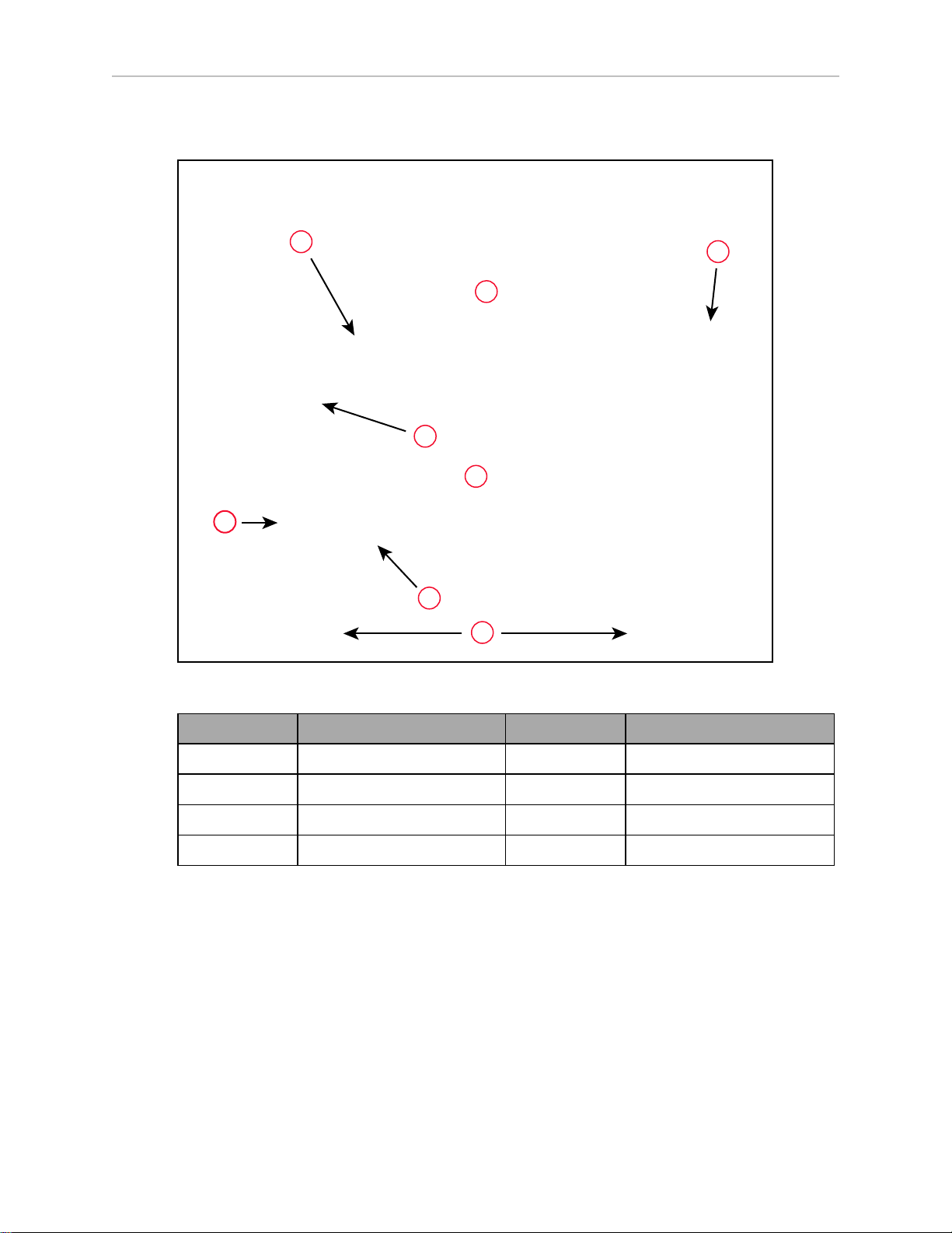
5.6 Description of Connectors on Robot Interface Panel
5.7 Cable Connections from Robot to SmartController
5.8 Connecting 24 VDC Power to Robot
Specifications for 24 VDC Robot and Controller Power 83
Details for 24 VDC Mating Connector 84
Procedure for Creating 24 VDC Cable 84
Installing 24 VDC Robot Cable 85
5.9 Connecting 200-240 VAC Power to Robot
Specifications for AC Power 86
Details for AC Mating Connector 89
Procedure for Creating 200-240 VAC Cable 89
Installing AC Power Cable to Robot 90
5.10 Grounding the Quattro Robot System
Quattro Robot Base 90
Quattro HS Robot Base 91
71
72
75
80
81
81
82
83
86
90
09955-000 Rev. N Quattro User's Guide 5
Page 6

Table of Contents
Robot-Mounted Equipment 91
Configuration 92
5.11 Installing User-Supplied Safety Equipment
Emergency Stop Circuits 99
Remote Manual Mode 100
User Manual/Auto Indication 101
User High Power On Indication 101
Remote High Power On/Off Control 101
High Power On/Off Lamp 102
Remote Front Panel or User-Supplied Control Panel Usage 102
Remote Pendant Usage 103
94
Chapter 6: System Operation 105
6.1 Robot Status Display Panel
6.2 Status Panel Fault Codes
6.3 Using the Brake-Release Button
Brakes 107
Brake-Release Button 107
6.4 Front Panel
6.5 Connecting Digital I/O to the System
6.6 Using Digital I/O on Robot XIO Connector
Optional I/O Products 114
XIO Input Signals 114
XIO Output Signals 116
XIO Breakout Cable 119
6.7 Starting the System for the First Time
Verifying Installation 121
Turning on Power and Starting ACE 122
Enabling High Power 123
Verifying E-Stop Functions 123
Verify Robot Motions 123
6.8 Quattro Motions
Straight-line Motion 124
Containment Obstacles 124
Tool Flange Rotation Extremes 124
6.9 Learning to Program the Quattro Robot
105
106
107
109
110
112
121
124
128
Chapter 7: Optional Equipment Installation 129
7.1 End-Effectors
Attaching 129
Aligning 129
Grounding 129
Accessing Vacuum 129
6 Quattro User's Guide 09955-000 Rev. N
129
Page 7

Table of Contents
7.2 Routing End-effector Lines
7.3 Ball Stud Locks
Installing a Ball Stud Lock 132
Removing a Ball Stud Lock 133
130
131
Chapter 8: Technical Specifications 135
8.1 Dimension Drawings
8.2 Internal Connections
8.3 XSYS/XSYSTEM Connector
8.4 Robot Specifications
8.5 Payload Specifications
Torque and Rotation Limits 147
Payload Mass vs. Acceleration 147
Payload Inertia vs. Acceleration 149
8.6 Stopping Times and Distances
8.7 Robot Mounting Frame, Quattro 650H Robot
135
144
145
145
147
150
158
Chapter 9: Maintenance - H 165
9.1 Periodic Maintenance Schedule
9.2 Warning Labels
9.3 Checking Safety Systems
9.4 Checking Robot Mounting Bolts
9.5 Checking Robot Gear Drives
9.6 Checking Fan Operation
9.7 Replacing the eAIB Chassis
Removing the eAIB Chassis 170
Installing a New eAIB Chassis 173
9.8 Commissioning a System with aneAIB
Safety Commissioning Utilities 175
E-Stop Configuration Utility 176
E-Stop Verification Utility 177
Teach Restrict Configuration Utility 177
Teach Restrict Verification Utility 178
9.9 Replacing the Encoder Battery Pack
Battery Replacement Interval 179
Battery Replacement Procedure 180
9.10 Replacing a Platform
Replacement 182
9.11 Configuration
9.12 Replacing a Ball Joint Insert
165
168
169
169
169
170
170
174
179
182
182
182
09955-000 Rev. N Quattro User's Guide 7
Page 8

Table of Contents
9.13 Replacing Outer Arm Spring Assemblies
Removing Outer Arm Spring Assemblies 183
Installing Outer Arm Spring Assemblies 184
9.14 Changing the Lamp in the Front Panel High-Power Indicator
182
186
Chapter 10: Maintenance - HS 189
10.1 Cleaning
Water Shedding 189
Wash-Down 189
Chemical Compatibility 190
10.2 Warning Labels
10.3 Periodic Maintenance
10.4 Checking Safety Systems
10.5 Checking Robot Mounting Bolts
10.6 Checking Robot Gear Drives
10.7 Checking Fan Operation
10.8 Removing and Installing the Cable Inlet Box
Removing the Cable Inlet Box 197
Installing the Cable Inlet Box 198
10.9 Replacing the eAIB Chassis
Removing the eAIB Chassis 199
Installing a New eAIBChassis 201
10.10 Commissioning a System with aneAIB
Safety Commissioning Utilities 203
E-Stop Configuration Utility 204
E-Stop Verification Utility 205
Teach Restrict Configuration Utility 205
Teach Restrict Verification Utility 206
10.11 Replacing the Encoder Battery Pack
Battery Replacement Interval 207
Battery Replacement Procedure 208
10.12 Replacing a Platform
Replacement 211
Configuration 212
10.13 Replacing a Ball Joint Insert
10.14 Replacing Outer Arm Spring Assemblies
Removing Outer Arm Spring Assemblies 213
Installing Outer Arm Spring Assemblies 214
10.15 Replacing the Front Panel
189
190
191
195
195
195
196
197
199
202
207
211
212
213
216
8 Quattro User's Guide 09955-000 Rev. N
Page 9

Table of Contents
Chapter 11: Robot Cleaning/ Environmental Concerns- H 217
11.1 Ambient Environment
Humidity 217
Temperature 217
11.2 Cleaning
Caustic Compatibility 218
Water Shedding 218
Wipe-Down 218
11.3 Cleanroom Classification
11.4 Design Factors
Robot Base and Components 218
Inner Arms 219
Ball Joints 219
Outer Arms 219
Springs 219
Platforms 219
11.5 Installing Cable Seal Kit
Overview 220
Installation Procedure 221
217
218
218
218
220
Chapter 12: Environmental Concerns - HS 227
12.1 Ambient Environment
Humidity 227
Temperature 227
12.2 Cleanroom Classification
12.3 Design Factors
Robot Base and Components 228
Inner Arms 228
Ball Joints 228
Outer Arms 228
Spring Assemblies 229
Platforms 229
227
228
228
Chapter 13: Status Codes 231
13.1 Status Panel Display
13.2 Status Codes
231
232
09955-000 Rev. N Quattro User's Guide 9
Page 10

Revision History
Revision
Code
01 June,
Date Revised Content
Original release.
2016
02 May, 2017 Regulatory updates.
03 November,
2017
l Added the Quattro 800HS to USDA approved list.
l Clarified that Line E-Stop Input can be used for pro-
duction lines.
l Clarified note on emergency stop circuits.
l Clarified that the ball joint inserts are made of special
acetal material.
04 April, 2018 l Updated safety chapter format and alert levels through-
out user guide.
l Clarified that USDA approved platforms are stainless
steel.
l Updated unpacking instructions with new crate con-
figuration.
l Updated recommended power supply model numbers.
l Updated images of platform to show Omron Adept logo.
l Changed ACE software disk to ACEsoftware media.
l Updated pictures to show painted inner arms.
l Add note to firmly hold end of arm tooling when attach-
ing to the flange to prevent damage to platform belt.
l Minor updates to fix broken links and incorrect ref-
erences.
05 March,
2019
l Updated copyright for 2019.
l Added WEEEdisposal information.
l Removed www.adept.com from Chapter 1: Introduction.
l Updated safety chapter format and added fire and ESD
alert icons.
l Added addition information regarding intended and non-
intended use of Quattro robots.
l Made a note that Hardstops have been moved to the
base.
l Added Max Allowable Center of Gravity (CG) table in
chapter 8.
l Graphics improved and modified for translation and
added call-out tables.
l Added Status Codes chapter.
l Added Platform configuration procedure to System
Installation chapter and removed configuration procedure from Maintenance chapters.
l Revised encoder battery replacement interval.
l Revised Ball Stud Lock section with new part number for
individual locks.
10 Quattro User's Guide 09955-000 Rev. N
Page 11

Revision
Code
Date Revised Content
l Many changes to Chapter 5: System Installation includ-
ing new and improved figures, content removal and additions.
l Operating temperature range, changed to 1 to 40°C
from previously noted 5 to 40°C.
l Added red CADversion of status codes to Status Panel
Fault Codes section in chapter 5.
l Dual robot configuration renamed to single and multiple
robot configuration.
l Removed references to obsolete sDIO module.
l Added IOBlox device to Table 6-3. Digital I/O Connection
Options
l Added a note about typical IOBlox configurations in
Chapter 6: System Operation.
09955-000 Rev. N Quattro User's Guide 11
Page 12

Page 13

Chapter 1: Introduction
1.1 Quattro Robots, Product Description
The Quattro robot is a four-axis parallel robot. The four identical axis motors control movement of the robot tool in X, Y, and Z directions, as well as Theta rotation.
Controllers
The Quattro robot requires a SmartController EX motion controller for control. That controller
can be combined with a user-supplied PLC, for programming.
The robot servo code runs on an SmartServo distributed-motion control platform embedded in
the robot base as part of the power amplifiers.
Sizes and Materials
There are two sizes of Quattro robots, each available with anodized aluminum or stainless
steel platforms:
l
Quattro 650H (AnodizedAluminum & SS) and Quattro 650HS (SS)
and
l
Quattro 800H (Anodized Aluminum &SS) and Quattro 800HS (SS)
The Quattro 650H and 800H areavailable with anodized aluminum or stainless
steel (SS) platforms, and anodized aluminum outer arm spoons. The eAIB and
cable box used with the two H models are anodized aluminum.
The Quattro 650HS and 800HS are USDAAccepted, and therefore only available
with stainless steel platforms and stainless steel outer arm spoons. The eAIB and
cable box used with the two HS models are electroless nickel (EN).
In most aspects, the robots are similar enough that they will be covered together. In areas
where there are significant differences, the Quattro H and Quattro HS robots will be presented
in two chapters, using titles such as Robot Installation—H for the 650H and 800H robots, and
Robot Installation—HS for the 650HS and 800HS robots.
Major Differences between Quattro H and HS Robots
Note that either anodized aluminum or stainless steel platforms can be used on the Quattro
650H and 800H robots.
The Quattro 650HS and 800HS are only available with stainless steel platforms.
09955-000 Rev. N Quattro User's Guide 13
Page 14

1.1 Quattro Robots, Product Description
Table 1-1. Quattro H/HS Differences
Standard (650H/800H) HS (650HS/800HS)
USDA Accepted
No Yes
(Meat and Poultry)
IP rating IP65, Option IP66, Standard
P30 Platform, no rotation Hard-anodized or Stainless Steel
Stainless Steel (SS)
(SS)
P31 Platform, 46.25° Hard-anodized or SS SS
P32 Platform, 92.5° Hard-anodized or SS SS
P34 Platform, 185° Hard-anodized or SS SS
Outer Arm Spoons Hard-Anodized Stainless Steel
Base Mounting Pad Holes M16-2.0, through-hole M16-2.0, blind, 40 mm
bolt
Base Coating material White polyurethane
powder
eAIB Black Anodized, Single-bolt
White ETFE, USDA
approved
EN, 6-bolt installation
installation
Cable Inlet box Hard-Anodized, Option EN, Standard
Cable Tray Not required Required (for USDA)
Status Display Half-height Full-height, to shield
labels
Protective Earth Ground On base-mounting pad In cable inlet box
Motor covers White Solid white, no label
Exposed bolts and screws all
No Yes
gasketed
Similarities Between the Quattro Robots
l
All models use the same motors
l
All models share the same base casting, although the H and HS have some machining
and coating differences. Platform coatings/materials differ for HS robots, but dimensions
do not.
l
The mounting hole pattern for the bases is the same.
l
All share the same inner arm design.
l
All have an eAIB.
14 Quattro User's Guide 09955-000 Rev. N
Page 15
Chapter 1: Introduction
Figure 1-1. Major Robot Components, Isometric View (650HS shown)
Callout Description Callout Description
A Mounting Pads F Motor Cover
B eAIB G Outer Arms
C Cable Inlet Box H Platform
D Base J Ball Joints (Spring Assemblies not shown)
E Inner Arm
eAIB
The power amplifiers for the Quattro robot are embedded in the base of the robot. This amplifier section is known as the Amplifiers in Base (eAIB)distributed motion control platform,
and provides closed-loop servo control of the robot amplifiers, as well as robot I/O. The eAIB is
available in either an anodized or electroless nickel finish.
The eAIB features:
l
On-board digital I/O: 12 inputs, 8 outputs
l
Low EMI for use with noise-sensitive equipment
l
No external fan for quiet operation
09955-000 Rev. N Quattro User's Guide 15
Page 16

1.1 Quattro Robots, Product Description
l
8 kHz servo rate to deliver low positional errors and superior path following
l
Sine-wave commutation to lower cogging torque and improve path following
l
Digital feed-forward design to maximize efficiency, torque, and velocity
l
Temperature sensors on all amplifiers and motors for maximum reliability and easy
troubleshooting
l
Hardware-based E-Stop and Teach Restrict controls
These are for improved safety relative to European standards implemented in 2012.
NOTE: The H and HSamplifiers and their cable inlet boxes are not interchangeable.
Quattro Robot Base
The Quattro robot base is an aluminum casting that houses the four drive motors, and supports the power amplifiers. It provides four mounting pads for attaching the base to a rigid
support frame. The Status Display Panel is mounted on the side of the robot base.
Inner Arms
The four robot motors attach directly to the inner arms through a high-performance gear reducer. Other than optional, user-supplied hardware mounted on the platform, these are the only
drive motors in the Quattro robot. The following figure shows an inner arm from a Quattro
robot. RIA-compliant hard stops limit the inner arm motion to -52° and +124°.
Figure 1-2. Inner Arm
Ball Joints, Outer Arms
The inner arm motion is transmitted to the platform through the outer arms, which are connected between the inner arms and platform with precision ball joints. The outer arms are carbon fiber epoxied assemblies with identical ball joint sockets at each end. A bearing insert in
16 Quattro User's Guide 09955-000 Rev. N
Page 17
Chapter 1: Introduction
D
A
E
F
C
G
H
B
each socket accepts the ball joint studs on the inner arms and platform, and allows for approximately ± 60° of relative motion. No ball joint lubrication is required.
Platforms
Figure 1-3. Quattro Ball Joint Assembly, Quattro HS Robot shown
Callout Description Callout Description
A Ball Joint Stud E Ball Joint Socket Insert
B Inner Arm F Outer Arm Springs
C Ball Joint Socket G Spring Horseshoe
D Pressed Pin H Outer Arms
Each pair of outer arms is held together with spring assemblies that pre-tension the ball joints.
The outer arms can be installed and removed without tools.
The platform converts the motion of the four Quattro motors into Cartesian motion and, for all
but the fixed platform, Theta rotation of the robot tool.
The Quattro robot currently supports four models of platforms, depending on the amount of
Theta rotation and inertia needed.
NOTE: The four models of platforms require different robot parameters.
09955-000 Rev. N Quattro User's Guide 17
Page 18

1.1 Quattro Robots, Product Description
The suffix on the part numbers that follow indicates the finish or material of the platform.
Refer to Materials and Finishes on page 20.
P31 Platform (P/N 09503-xxx)
The P31 platform has a rotation range of ±46.25°. The tool flange is machined into one of the
pivot links. It does not rotate in relation to the pivot link, so there are no gears or belts
involved. See P31 Platform on page 18.
P30 Platform (P/N 09730-xxx)
The P30 platform is a fixed platform that provides no Theta rotation. The tool flange is
machined into the one-piece platform. See P30 Platform on page 19.
P32 Platform (P/N 09732-xxx)
The P32 platform has a rotation range of ±92.5°. The tool flange is mounted on one of the pivot
links. See P32 Platform on page 19.
P34 Platform (P/N 09734-xxx)
The P34 platform has a rotation range of ±185°. The tool flange is mounted on one of the pivot
links.
Figure 1-4. P31 Platform
18 Quattro User's Guide 09955-000 Rev. N
Page 19

Figure 1-5. P30 Platform
Chapter 1: Introduction
Figure 1-6. P32 Platform
NOTE: The only visible difference between the P32 and P34 platforms is the
model number, and the two or four dots immediately below that number. Two
dots designate a P32 platform.
09955-000 Rev. N Quattro User's Guide 19
Page 20

1.1 Quattro Robots, Product Description
Materials and Finishes
Platforms are available in:
l
Aluminum with hard-anodized finish
l
Stainless steel
The following table shows which materials and finishes are compatible with which robots:
650H 650HS 800H 800HS Part Number
Hard
Yes No Yes No XXXXX-000
Anodized
Stainless
Yes Yes Yes Yes XXXXX-200
Steel
Platform Clocking
Rotational platforms are constructed such that the clocking, or rotational alignment, of the platform relative to the robot base is critical. This is detailed in Clocking the Platform to the Base
on page 40.
Platform Shipping
l
The platform and outer arms are removed.
l
The platform is shipped pre-assembled as a unit.
You will need to connect the outer arms between the inner arms and the platform to
reassemble the robot. The outer-arm assemblies are interchangeable.
Any end-effectors and their air lines and wiring are user-supplied.
SmartController EX
The SmartController motion controller is the foundation of our family of high-performance, distributed motion controllers. The SmartController EX is designed for use with:
l
Quattro robots
l
eCobra 600/800 robots
l
Viper robots
The controller supports a conveyor tracking option, as well as other options. The SmartController EX uses the eV+ operating system. It offers scalability and support for IEEE 1394-based
digital I/O and general motion expansion modules. The IEEE 1394 interface is the backbone of
SmartServo, our distributed controls architecture supporting our products. The SmartController
EX also includes Fast Ethernet and DeviceNet.
20 Quattro User's Guide 09955-000 Rev. N
Page 21
Refer to the SmartController EX User’s Guide for SmartController specifications.
1.2 Installation Overview
The system installation process is summarized in the following table. Also, refer to System
Installation on page 71.
NOTE: For multi-robot installations, see the Single and Multiple Robot Configuration Guide.
Chapter 1: Introduction
Figure 1-7. SmartController EX
Table 1-2. Installation Overview
Task to be Performed Reference Location
Mount the cable box (Quattro HS robot or Quattro H
robot with IP65 option).
Mount the robot to a level, stable mounting frame. Mounting the Robot Base on page
Attach the robot outer arms and platform. Attaching the Outer Arms and Plat-
Install the SmartController, Front Panel, Pendant (if
purchased), and ACE software.
Install the IEEE 1394 and XSYS cables between the
robot and SmartController.
Create a 24 VDC cable and connect it between the
SmartController and the user-supplied power supply.
Create a 24 VDC cable and connect it between the
robot and the user-supplied 24 VDC power supply.
Create a 200-240 VAC cable and connect it between
the robot and the facility AC power source.
Cable Inlet Box on page 50 and
Installing Cable Seal Kit on page
220.
34.
form on page 39.
Installing the SmartController EX on
page 72.
Cable Connections from Robot to
SmartController on page 82.
Installing the SmartController EX on
page 72.
Connecting 24 VDC Power to Robot
on page 83.
Connecting 200-240 VAC Power to
Robot on page 86.
Install user-supplied safety barriers in the workcell. Installing User-Supplied Safety
Equipment on page 94.
Connect digital I/O through the robot XIO connector. Using Digital I/O on Robot XIO Con-
09955-000 Rev. N Quattro User's Guide 21
Page 22

1.3 How Can I Get Help?
Task to be Performed Reference Location
nector on page 112.
Start the system, including system start-up and testing operation.
Install optional equipment, including end-effectors,
user air and electrical lines, external equipment, etc.
1.3 How Can I Get Help?
For support or service, contact your local Omron support.
Refer to additional information sources on our corporate website:
http://www.ia.omron.com
Related Manuals
This manual covers the installation, operation, and maintenance of an Quattro robot system.
There are additional manuals that cover programming the system, reconfiguring installed components, and adding optional components. See the following table. These manuals are available on the software media shipped with each system.
Manual Title Description
Starting the System for the First Time
on page 121.
End-Effectors on page 129.
Table 1-3. Related Manuals
Robot Safety Guide Contains safety information for our robots.
SmartController EX User’s
Guide
ePLC Connect 3 User’s Guide Describes the installation and use of the ePLC Connect 3 soft-
ACE User’s Guide Describes the installation and use of ACE software.
Single and Multiple Robot
Configuration Guide
T20 Pendant User's Guide Describes the use of the optional T20 manual control pendant.
Contains complete information on the installation and operation of the SmartController EX.
ware, for using a user-supplied PLC as controller.
Contains cable diagrams and configuration procedures for a
single and multi-robot system.
22 Quattro User's Guide 09955-000 Rev. N
Page 23

Chapter 2: Safety
!
2.1 What to Do in an Emergency / Abnormal Situation
Press the E-Stop button (a red push-button on a yellow background) and then follow the
internal procedures of your company or organization for a robot emergency situation. If a fire
occurs, use a type D extinguisher: foam, dry chemical, or CO2.
Releasing the Brakes
In case of an emergency or abnormal situation, the platform can be manually moved without
electric power. However, only qualified personnel who have read and understood this manual
and the Robot Safety Guide should manually move the platform to a safe state. The brakes can
be released with the brake release button on Status Display Panel, see Robot Status Display
Panel on page 105. This requires 24 V power, and an E-Stop must be pressed on the robot. All
robot axes are held by brakes, which can be released with the brake release button. Remote
brake release feature is also available via XIO Input 6.2 (Pin 18) configuration, see Remote
Brake Release Feature on page 108.
General Hazards
IMPORTANT: The following situations could result in injury or damage to the
equipment.
l
Do not place objects on the Platform or Base of the robot.
l
Do not exceed the maximum payload capacity.
l
Do not exceed the maximum recommended limits given in technical specifications. See
Technical Specifications on page 135.
Rotational speed becomes more significant when the payload’s center of gravity is
farther away (vertically and/ or horizontally) from the platform’s center of gravity.
l
Do not drop the robot, put uneven weights on the outer arms or otherwise operate it irresponsibly.
l
Do not use unauthorized parts.
Releasing an E-Stop
CAUTION: PERSONALINJURYORPROPERTYDAMAGERISK
If the robot’s E-Stop is triggered, ensure that the cause of the E-Stop is resolved,
before releasing the E-Stop.
After the E-Stop button has been manually released, the robot will wait until the motors are
manually enabled.
There are three ways to enable the motors:
09955-000 Rev. N Quattro User's Guide 23
Page 24
2.2 Dangers, Warnings, and Cautions
!
!
!
!
l
Enable power through ACE software installed on your PC
l
Press the green ROBOT POWER button on the Front Panel
l
Press the ROBOTPOWER button on the Pendant
Once the motors are enabled, the robot will wait two seconds and then resume commanded
motion, if there is adequate space to maneuver.
2.2 Dangers, Warnings, and Cautions
Alert Levels
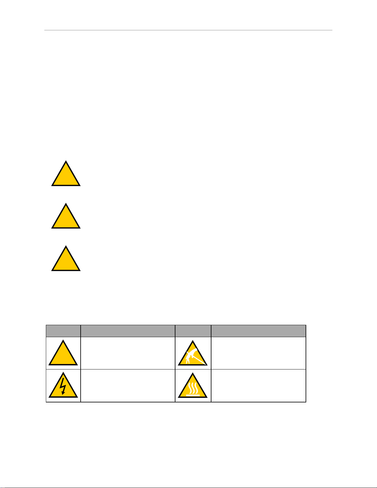
There are three levels of alert notation used in our manuals. In descending order of importance, they are:
DANGER: Identifies an imminently hazardous situation which, if not
avoided, is likely to result in serious injury, and might result in fatality or
severe property damage.
WARNING: Identifies a potentially hazardous situation which, if not avoided,
will result in minor or moderate injury, and might result in serious injury, fatality, or significant property damage.
CAUTION: Identifies a potentially hazardous situation which, if not avoided,
might result in minor injury, moderate injury, or property damage.
Alert Icons
The icon that starts each alert can be used to indicate the type of hazard. These will be used
with the appropriate signal word - Danger, Warning, or Caution - to indicate the severity of the
hazard. The text following the signal word will specify what the risk is, and how to avoid it.
Icon Meaning Icon Meaning
This is a generic alert icon. Any
specifics on the risk will be in the
text following the signal word.
This identifies a hazardous electrical situation.
This identifies a hazardous ESD
situation.
This identifies a hazardous burnrelated situation.
24 Quattro User's Guide 09955-000 Rev. N
Page 25
Special Information
!
There are several types of notation used to call out special information.
IMPORTANT: Information to ensure safe use of the product.
NOTE: Information for more effective use of the product.
Additional Information: Offers helpful tips, recommendations, and best prac-
tices.
Version Information: Information on differences in specifications for different
versions of hardware or software.
2.3 User's Responsibilities
Safe use of the Quattro robot is your responsibility. Safe use includes:
l
Reading the installation and operation instructions, as well as the Robot Safety Guide,
before using the equipment.
Chapter 2: Safety
l
Ensuring that the environment is suitable for safe operation of the robot.
l
Ensuring that anyone working with or near a robot has been adequately trained, and is
following this guide and the Robot Safety Guide for safe robot operation.
l
Maintaining the robots so that their control and safety functions continue to work properly.
Electrical Hazards
WARNING: ELECTROCUTIONRISK
Quattro robots use 200-240 VAC power. Thus, appropriately-sized branch circuit protection and lockout/ tagout capability must be provided in accordance
with National Electrical Code and any local codes.
Pinch Hazard
Robots' Arm Spring Assemblies
CAUTION: PINCHRISK
Ball joints are spring-loaded. Be careful not to pinch your fingers.
Qualification of Personnel
It is the end-user’s responsibility to ensure that all personnel who will work with or around
robots have attended an appropriate Omron training course and have a working knowledge of
the system. The user must provide the necessary additional training for all personnel who will
be working with the system.
09955-000 Rev. N Quattro User's Guide 25
Page 26

2.4 Robot Behavior
!
As noted in this and the Robot Safety Guide, certain procedures should be performed only by
skilled or instructed persons. For a description of the level of qualification, we use the standard
terms:
l
Skilled persons have technical knowledge or sufficient experience to enable them to
avoid the dangers, electrical and/or mechanical
l
Instructed persons are adequately advised or supervised by skilled persons to enable
them to avoid the dangers, electrical and/or mechanical
All personnel must observe industry-prescribed safety practices during the installation, operation, and testing of all electrically-powered equipment.
IMPORTANT: Before working with the robot, every entrusted person must confirm that they:
l
Have the necessary qualifications
l
Have received the guides (both this user’s guide, and the Robot Safety Guide)
l
Have read the guides
l
Understand the guides
l
Will work in the manner specified by the guides
2.4 Robot Behavior
Hardstops
The robot’s hardstops are located at the base. If the robot runs into one of its hardstops, the
robot’s motion will stop completely, the system will generate an envelope error, and power
will be cut to the robot motors.
The robot cannot continue to move after hitting a hardstop until you clear the error.
The robot’s hardstops can stop the robot at any speed, load, and maximum or minimum extension.
2.5 Intended and Non-intended Use
Intended Use
The normal and intended use of these robots does not create hazards. The Quattro robot has
been designed and constructed in accordance with the relevant requirements of IEC60204-1.
The Quattro robot is intended for use in parts assembly and material handling for payloads up
to 6.0 kg (13.2 lb), for anodized platforms, and payloads up to 3 kg (6.6 lb) for stainless steel
platforms. See Technical Specifications on page 135 for complete information on the robot specifications. Refer to the Robot Safety Guide for details on the intended use of our robots.
WARNING: PERSONALINJURYRISK
Quattros are not collaborative robots. They require a dedicated work area that
will prevent personnel from coming into contact with them during operation.
26 Quattro User's Guide 09955-000 Rev. N
Page 27

Guidelines for safe use:
l
Clean, dry surfaces— The Quattro robot is designed to be compatible with standard
cleaning and operational needs for secondary food packaging, as well as less stringent
requirements. The platform and the arms, are IP67 rated. The base of the Quattro H
robot, is IP65 rated, and for the Quattro HS robot, the rating is IP66.
IMPORTANT: For standard Quattro H robot, the topside of the base is
IP20 rated, and therefore must not be exposed to liquid.
l
Temperature — 1 to 40°C (34 to 104°F), with a recommended humidity range of 5% to
90%, non-condensing.
Non-Intended Use
The Quattro robots are not intended for use in any of the following situations:
l
Use in the presence of ionizing or non-ionizing radiation
l
Use in potentially explosive atmospheres
l
Use in medical or life saving applications
Chapter 2: Safety
l
Use in a residential setting (they are for industrial use only)
l
Use before performing a risk assessment
l
Where the equipment will be subject to extremes of heat or humidity
Non-intended use of Quattro robots can:
l
Cause injury to personnel
l
Damage itself or other equipment
l
Reduce system reliability and performance
If there is any doubt concerning the application, ask your Omron Support to determine if it is
an intended use or not.
Robot Modifications
If the user or integrator makes any changes to the robot, it is their responsibility to ensure that
there are no sharp edges, corners, or protrusions.
Note that any change to the robot can lead to loss in safety or functionality. The user or integrator must ensure that all safety features are operational after modifications.
2.6 Additional Safety Information
Contact your local Omron support for other sources of safety information:
09955-000 Rev. N Quattro User's Guide 27
Page 28

2.6 Additional Safety Information
Robot Safety Guide
The Robot Safety Guide, which ships with every robot system, provides detailed information
on safety for Omron Adept Technologies, Inc. robots. It also gives resources for information on
relevant standards.
T20 Manual Control Pendant (Option)
The protective stop category for the pendant enable switch is category 1, which complies with
the requirements of ISO 10218-1. The pendant's design is in accordance with the requirements
of IEC 60204-1 and ISO 13849. The E-Stop button complies with ISO 13850.
NOTE: Omron Adept Technologies, Inc. does not offer a wireless pendant.
The manual control pendant can only move one robot at a time, even if your network contains
multiple robots.
Disposal
Dispose of in accordance with applicable regulations.
Customers can contribute to resource conservation and protecting the environment by the
proper disposal of WEEE (Waste Electronics and Electrical Equipment). All electrical and electronic products should be disposed of separately from the municipal waste system via designation collection facilities. For information about disposal of your old equipment, contact
your local Omron support.
28 Quattro User's Guide 09955-000 Rev. N
Page 29

Chapter 3: Robot Installation - H
3.1 Transport and Storage
This equipment must be shipped and stored in a temperature-controlled environment, within
the range –25 to +60°C (-13 to 140°F). The recommended humidity range is 5% to 90%, non-condensing. It should be shipped and stored in the supplied crate, which is designed to prevent
damage from normal shock and vibration. You should protect the crate from excessive shock
and vibration.
Use a forklift, pallet jack, or similar device to transport and store the packaged equipment.
The robot must always be stored and shipped in an upright position in a clean, dry area that
is free from condensation. Do not lay the crate on its side or any other non-upright position.
This could damage the robot.
The Quattro robot weighs 118 to 123 kg (260 to 271 lb) with no options installed.
3.2 Unpacking and Inspecting the Equipment
Before Unpacking
Before unpacking, carefully inspect all shipping crates for evidence of damage during transit. If
any damage is indicated, request that the carrier’s agent be present at the time the container is
unpacked.
Upon Unpacking
Before signing the carrier’s delivery sheet, compare the actual items received (not just the packing slip) with your equipment purchase order. Verify that all items are present and that the
shipment is correct and free of visible damage.
l
If the items received do not match the packing slip, or are damaged, do not sign the
receipt. Contact your local Omron support as soon as possible (see How Can I Get
Help? on page 22).
l
If the items received do not match your order, please contact your local Omron support
immediately.
Retain all containers and packaging materials. These items may be necessary to settle claims
or, at a later date, to relocate the equipment.
Unpacking
The Quattro robot is shipped in a wooden crate that holds the robot base, outer arms, platform,
controller, miscellaneous hardware, and any accessories ordered.
The top of the crate should be removed first.
09955-000 Rev. N Quattro User's Guide 29
Page 30

3.2 Unpacking and Inspecting the Equipment
Figure 3-1. Robot Base in Crate, (A) Outer Arms
The robot base is shipped with the inner arms attached. The outer arms are assembled in
pairs, packed in a cardboard box at the bottom of the crate. The platform is shipped fully
assembled, but separate from the robot base and outer arms.
1. Remove the ancillary items (controller, outer arms, platform, etc.) that are in cardboard
boxes and attached to the crate bottom.
Figure 3-2. Outer Arms
2.
The robot base is secured to the crate with four machine bolts, one in each crate post.
Place a protective pad over the eAIB to protect it from damage from tools during the
removal of the bolts.
3.
Remove the bolt from each crate post.
30 Quattro User's Guide 09955-000 Rev. N
Page 31

3.3 Repacking for Relocation
!
Chapter 3: Robot Installation - H
Figure 3-3. Removal ofBolt
If the robot or other equipment needs to be relocated, reverse the steps in the installation procedures in this chapter. Reuse all original packing containers and materials and follow all
safety notes used for installation. Improper packaging for shipment will void your warranty.
CAUTION: PROPERTYDAMAGERISK
The robot must always be shipped in an upright orientation.
3.4 Environmental and Facility Requirements
The Quattro robot system installation must meet the operating environment requirements
shown in the following table.
Table 3-1. Robot System Operating Environment Requirements
Ambient temperature 1 to 40°C (34 to 104°F)
Humidity 5% to 90%, non-condensing
Altitude up to 2000 m (6500 ft)
Pollution degree 2
Protection class: robot base IP65 (with optional cable sealing kit)
Protection class: arms, platform IP67
Note: For robot dimensions, see Technical Specifications on page 135.
Note: For power requirements, see Connecting 24 VDC Power to Robot on page 83 and Con-
necting 200-240 VAC Power to Robot on page 86.
09955-000 Rev. N Quattro User's Guide 31
Page 32

3.5 Mounting Frame
A
4x
A
4x
2x
B
20x
A
4x
C
1800.0
2000.0
2000.0
A
B
A
Note: The SmartController must be installed inside a NEMA-1 rated enclosure. The controller must not come into contact with liquids.
3.5 Mounting Frame
The Quattro robot is designed to be mounted above the work area suspended on a user-supplied frame. The frame must be adequately stiff to hold the robot rigidly in place while the
robot platform moves within the workspace.
While we do not offer robot frames for purchase, and the frame design is the responsibility of
the user, we provide here some general guidelines as a service to our users. We make no representation or warranty with respect to these guidelines, or the rigidity and longevity of the
structure designed and built by the user or for the user by a third party using these guidelines.
In addition, when the robot is mounted on the structure based on these guidelines, We do not
guarantee that the robot will perform to the specifications given in this product documentation, due to user’s frame or user’s production environmental factors.
As an example, a sample frame design is presented and discussed. For generalized application
performance, frames built to the specifications of this sample should experience no degradation in robot performance due to frame motions. Applications requiring higher than 6 kg * 10
g forces across the belt and/or 6 kg * 3 g along the belt may require a stiffer frame design.
Figure 3-4. Sample Quattro Mounting Frame, (A) See Detail 1, (B) See Detail 2
NOTE: More specifications for the sample frame are provided in Robot Mounting Frame, Quattro 650H Robot on page 158.
32 Quattro User's Guide 09955-000 Rev. N
Page 33

Chapter 3: Robot Installation - H
Any robot’s ability to settle to a fixed point in space is governed by the forces, masses, and
accelerations of the robot. Since “every action has an equal and opposite reaction”, these forces
are transmitted to the robot frame and cause the frame and base of the robot to move and possibly vibrate in space. As the robot system works to position the tool flange relative to the base
of the robot, any frame or base motion will be “unobservable” to the robot system, and will be
transmitted to the tool flange. This transmitted base motion will result in inertial movement of
the tool flange mass, and will cause disturbance forces to be introduced into the robot control
system. These disturbance forces cause “work” to be done by the robot servo control system
which may result in longer settling times for robot operations.
It is important to note that, even after the system reports the robot to be fully settled, the tool
flange will still be moving by any amount of motion that the suspended base of the robot may
be experiencing.
Frame Orientation
The sample robot frame design is stiffer in one direction than the other. This is to accommodate conveyor belt applications where the robot is moving with much more acceleration
across a conveyor belt than along it. The conveyor should generally be aligned so that the belt
travel is along the robot World Y-axis, and the mid-height frame members cross the belt at a
90° angle. The across-the-belt dimension of the frame should be minimized to get the best performance of the robot in that direction. While this frame design assumes a 1.8 m across-thebelt frame dimension, a 1.5 m dimension would offer increased stiffness and possibly
increased robot performance at high accelerations and payloads. The mid-height horizontal
members are important to the frame stiffness, and should be located as close to the belt as possible.
For applications requiring high accelerations along the direction of belt travel, consideration
should be given to strengthening the frame in that direction.
Frame Construction
Typically, the frame is constructed of welded steel members. Hygiene-sensitive applications
may call for stainless steel fabrication, with care taken to seal up all possible voids and grind
smooth all weld joints. For other applications, it may be suitable to manufacture the frame of
carbon steel and paint the resulting assembly. The frame design presented here is based on a
stainless steel construction using 10 mm thick members. It may be reasonable to use a reduced
thickness for carbon steel assemblies. Some customers may choose to use tubular members, or
turn horizontal members at 45° angles to facilitate water runoff from the flat frame surfaces.
Robot-to-Frame Considerations
The Quattro has a moderately-complex mounting requirement due to the nature of the parallelarm kinematics and the need to minimize the robot size and mass. Arm Travel Volume (650
shown) (units in mm) on page 143 shows the inner arm travel and how it may encroach on
the robot mounting points. As a starting point, for a frame that is 2 meters in each direction,
(allowing use of the full range of the Quattro 650 robots), you should attempt to attain a frame
frequency of 25 Hz.
For specialized applications, such as heavy payloads and/or aggressive moves, you may want
to attain a frame frequency of 40 Hz.
In general, a smaller frame will yield a higher frequency. If you aren’t going to use the entire
work envelope, you can increase the frequency simply by using a smaller frame.
09955-000 Rev. N Quattro User's Guide 33
Page 34

3.6 Mounting the Robot Base
!
A lower frequency frame, more aggressive robot moves, and heavier payloads will all contribute to longer settling times.
Mounting
The robot mounts in four locations, as detailed in the drawings. The holes are tapped for an
M16 x 2.0 bolt. The Quattro robot may be mounted from the top or bottom of the frame. A
crane or forklift should be used to position the robot. If lifted from above, the robot must be lifted by user-supplied eyebolts and slings.
Mounting Hole Dimensions, Quattro H Robots, (A) Detail A, (B) Detail B (units in mm) on
page 136 shows the mounting hole pattern for the Quattro robot. Note the hole location and
mounting pad tolerances for position and flatness.
Deviation from this flatness specification will, over time, cause a possible loss of robot calibration. If the frame does not meet this flatness specification, use shims to achieve it.
NOTE: We suggest welding the robot mounting tabs as a last step in the frame
fabrication, using a flat surface as a datum surface during the tack welding operation.
Gussets
The triangular gussets are an integral part of the frame stiffness. The vibrational strength of a
structural assembly is strongly governed by controlling the shear forces between members. The
250 mm gussets, shown in Sample Quattro Mounting Frame, (A) See Detail 1, (B) See Detail 2
on page 32, are nominally sufficient for transferring the load from the vertical members into
the horizontal cross pieces. Preferably, gussets should be placed at the edges of the frame members to transfer the loading into the walls of the members, instead of the faces, and enable
easier cleaning. Some frame designs may benefit from extending these gussets to 500 mm in
the vertical direction, as the design intent of the gussets is mainly to secure the long vertical
members from rotating out of position. For this reason, the gussets to the across-the-belt horizontal member should be at the bottom of the member, as shown in Sample Quattro Mounting
Frame, (A) See Detail 1, (B) See Detail 2 on page 32, and as close to the vertical midplane of the
frame as feasible (15 mm thickness is adequate for most situations).
3.6 Mounting the Robot Base
NOTE: All mounting hardware is user-supplied.
CAUTION: PERSONALINJURYORPROPERTYDAMAGERISK
Remove all ancillary components (controller, outer arms, platform, etc.) from
the shipping crate before lifting the robot base.
Robot Orientation
We recommend mounting the Quattro robot so that the Status Display Panel faces away from
the conveyor belt. Although the work envelope of the robot is symmetrical, this orientation
gives better access to the status display, status LED, and Brake-Release button. It also balances
the arm loading for aggressive moves across the belt.
34 Quattro User's Guide 09955-000 Rev. N
Page 35

Chapter 3: Robot Installation - H
!
!
This orientation places the robot World Y-axis along the conveyor belt, and the X-axis across
the belt.
Mounting Surfaces
Mounting surfaces for the robot mounting flanges must be within 0.75 mm of a flat plane. If
the surfaces do not meet this tolerance, use shims to attain it.
NOTE: Failure to mount the Quattro robot within 0.75mm of a flat plane will
result in inconsistent robot motions.
Mounting Options
Using the mounting frame design provided, there are several options for mounting the Quattro
robot:
l
Lower the robot into the frame from above, or
Lift the robot into the frame from below.
l
Place the robot mounting pads on top of the frame mounting pads, or
Place the robot mounting pads under the frame mounting pads.
l
Mounting hardware can be bolts threaded directly into the robot base mounting pads,
or bolts that go through the robot base mounting pads into nuts.
WARNING: PERSONALINJURYORPROPERTYDAMAGERISK
Do not attempt to lift the robot from any points other than with eyebolts or
slings as described here, or with a padded board, as described here.
Mounting Procedure from Above the Frame
The Quattro robot has four mounting pads. Each pad has one M16 x 2.0 threaded throughhole. The robot can be mounted either on top of the frame pads, using the bottom surface of the
robot base mounting pads, or to the bottom of the frame pads, using the top surface of the
robot base mounting pads.
Mounting to Top of Frame Pads
This procedure uses two user-supplied M16 x 2.0 eyebolts and jam nuts.
1.
Remove all lag bolts from the robot base mounting pads.
2.
Screw the M16 eyebolts into opposing robot mounting pads, so that the robot will be balanced when lifted.
3.
Lock each eyebolt with a jam nut.
4.
Connect slings to the M16 eyebolts and take up any slack in the slings.
WARNING: PERSONALINJURYORPROPERTYDAMAGERISK
Do not to lift the robot from any points other than the eyebolts. Failure to comply could result in the robot falling and causing either injury or equipment
damage.
09955-000 Rev. N Quattro User's Guide 35
Page 36

3.6 Mounting the Robot Base
A
A
5.
Lift the robot and position it directly over the mounting frame.
6.
Slowly lower the robot while aligning the M16 holes in the robot mounting pads with
the holes in the frame mounting pads.
7.
When the mounting pad surfaces are touching, start a bolt in each of the two unused
mounting holes. Refer to Install Mounting Hardware on page 37.
8.
Remove the slings and M16 eyebolts.
9.
Follow the instructions in Install Mounting Hardware on page 37.
Mounting to Bottom of Frame Pads
NOTE: Since eyebolts would be in the way of this mounting method, you will
have to use slings or other means to lift the robot base. Nylon slings can be
wrapped across the center of the robot base, away from the inner arms. See the
following figure.
1.
Remove all lag bolts from the mounting pads before lifting the robot base.
2.
Wrap slings around the robot base. See the following figure for two methods.
NOTE: Make sure the slings do not touch the status panel or inner arms.
Figure 3-5. Location of Slings for Lifting Robot Base, (A) Slings
3.
Lift the robot and position it directly over the mounting frame.
4.
Slowly lower the robot while rotating it slightly, so that the four mounting pads are
lowered past the frame mounting pads without touching.
5.
When the robot base mounting pads are below the lower surface of the frame mounting
pads, rotate the robot base so that the M16 threaded holes in the robot base mounting
pads align with the holes in the frame mounting pads.
6.
Lift the robot base up, keeping the holes in the robot base pads and the frame pads
aligned, until the top surfaces of the robot base pads are touching the bottom surface of
36 Quattro User's Guide 09955-000 Rev. N
Page 37

Chapter 3: Robot Installation - H
the frame mounting pads.
7.
Follow the instructions in Install Mounting Hardware on page 37.
Mounting Procedure from Below the Frame
The Quattro robot has four mounting pads. Each pad has one M16 x 2.0 threaded hole. The
robot can be mounted either on top of the frame pads, using the bottom surface of the robot
base pads, or to the bottom of the frame pads, using the top surface of the robot base pads.
The Quattro robot can be mounted from beneath the mounting frame using a forklift. Use a
padded board as a support under the robot base. The robot base can be rotated by hand, once
mounted on the lifting pad on a forklift, when needed for clearing obstacles.
Mounting to Bottom of Frame Pads
1.
Remove all lag bolts from the mounting pads before lifting the robot base.
2.
Lift the robot and position the robot directly under the mounting frame.
3.
Slowly lift the robot and align the M16 holes in the robot mounting pads with the holes
in the frame mounting pads.
4.
Lift the robot until the top of the robot base mounting pads are touching the bottom of
the frame mounting pads.
5.
Follow the instructions in Install Mounting Hardware on page 37.
Mounting to Top of Frame Pads
1.
Remove all lag bolts from the mounting pads before lifting the robot base.
2.
Lift the robot so the mounting pads are directly under the mounting pads of the frame.
3.
Slowly lift the robot while rotating it slightly, so that the four mounting pads are raised
past the frame mounting pads without touching.
4.
When the robot base mounting pads are above the top surface of the frame mounting
pads, rotate the robot base back, so that the M16 threaded holes in the robot base mounting pads align with the holes in the frame mounting pads.
5.
Slowly lower the robot base while aligning the M16 holes in the robot mounting pads
with the holes in the frame mounting pads.
6.
Continue lowering the robot base until the bottom surface of the robot base mounting
pads are touching the top surface of the frame mounting pads.
7.
Follow the instructions in Install Mounting Hardware on page 37.
Install Mounting Hardware
NOTE: When mounting the robot, note the following:
l
The base casting of the robot is aluminum and can be dented if bumped against a
harder surface.
l
Verify that the robot is mounted squarely before tightening the mounting bolts.
l
All mounting hardware is user-supplied.
09955-000 Rev. N Quattro User's Guide 37
Page 38

3.6 Mounting the Robot Base
1.
Place split lock, then flat washers on the bolts.
Bolts are M16 x 2.0 if threaded into the robot base mounting tabs.
Bolts are M12 or ½ in. if going through the robot base mounting tabs into nuts.
NOTE: When M16 x 2.0 bolts are used, the bolt must engage at least 24 mm
into the threads of the base mounting pad.
2.
Insert the bolts through the holes in the frame mounting pads and into the threaded
holes in the robot base mounting pads.
If using through-bolts, insert the bolts through the holes in both the mounting pads and
through the threaded holes in the robot base mounting pads into nuts.
3.
Tighten the mounting hardware to the specifications listed in the following table.
NOTE: Check the tightness of the mounting bolts one week after initial installation, and then recheck every 6 months. For periodic maintenance, see Periodic
Maintenance Schedule on page 165.
Table 3-2. Mounting Bolt Torque Specifications
Standard Size Minimum Specification Torque
Threaded into base (aluminum):
Metric M16 x 2.0 ISO Property Class 5.8 98 N·m (74 ft-lb)
Using base mounting pad hole as through-hole:
Metric M12 ISO Property Class 9.8 100 N·m (75 ft-lb)
SAE ½ in. 100 N·m (75 ft-lb)
38 Quattro User's Guide 09955-000 Rev. N
Page 39

3.7 Attaching the Outer Arms and Platform
D
A
E
F
C
G
H
J
B
E
Chapter 3: Robot Installation - H
Callout Description Callout Description
A Mounting Pads F Motor Cover
B eAIB G Outer Arms
C Cable Inlet Box H Platform
D Base J Ball Joints (Spring Assemblies not shown)
Figure 3-6. Major Robot Components, Top View
E Inner Arm
The Quattro robot platform is attached to the inner arms by the outer arms.
NOTE: Except for attaching the outer arms and end-effector tooling, the platform
is shipped fully assembled.
09955-000 Rev. N Quattro User's Guide 39
Page 40

3.7 Attaching the Outer Arms and Platform
Clocking the Platform to the Base
The rotational alignment (clocking) of the platform to the base is critical to the correct operation of the Quattro robot.
NOTE: Incorrect clocking of the platform will result in incorrect robot performance.
l
On the hard-anodized and stainless steel platforms, the ends of the platform crosspieces (between each pair of ball studs) are labeled with numbers (1–4).
In addition, +X and +Y World Coordinates are labeled on the platform near the flange.
See the following figure.
l
When installing the platform, the numbers on the platform must match the numbers on
the underside of the robot base.
Figure 3-7. Platform Orientation Labeling (P32 shown)
Version Information: The labeling on all anodized platforms is the same except
for the part number.
40 Quattro User's Guide 09955-000 Rev. N
Page 41

Chapter 3: Robot Installation - H
X+
Y+
3
41
2
A
!
Figure 3-8. Platform Orientation, P31 Platform, (A) Tool Flange
Attaching the Outer Arms
One pair of outer arms attaches between each inner arm and the platform. No tools are needed
to install or remove the outer arms.
l
Each outer arm has a ball joint socket at each end.
l
The inner arms and the platform have corresponding pairs of ball studs.
CAUTION: PINCHRISK
Ball joints are spring-loaded. Be careful not to pinch your fingers.
Figure 3-9. Inner Arm Ball Studs
09955-000 Rev. N Quattro User's Guide 41
Page 42

3.7 Attaching the Outer Arms and Platform
D
A
E
F
C
G
H
B
!
l
Outer arm pairs are shipped assembled. Each pair has two springs and two horseshoes
at each end.
Figure 3-10. Ball Joint Assembly (Quattro HS shown)
Callout Description Callout Description
A Ball Joint Stud E Ball Joint Socket Insert
B Inner Arm F Outer Arm Springs
C Ball Joint Socket G Spring Horseshoe
D Pressed Pin H Outer Arms
CAUTION: PROPERTYDAMAGERISK
Ensure that the bearing insert is in place in the end of each outer arm. If an
insert has fallen out of the arm, press it back into place, ensuring that the insert
is centered and bottomed-out in the ball joint socket.
NOTE: In the following steps, take care not to trap debris between the ball studs
and their sockets.
42 Quattro User's Guide 09955-000 Rev. N
Page 43

Chapter 3: Robot Installation - H
!
NOTE: The procedure for attaching outer arms is the same for all platforms.
1.
Attach one pair of outer arms to each inner arm.
a.
As illustrated in the following figure, this is most easily achieved by pivoting the
two arms away from each other lengthwise.
This requires the least stretching of the spring to attach the ball joints.
b.
Slip one ball joint socket over the corresponding ball stud.
c.
Swing the bottom end of the outer arm pair sideways as you slip the other ball
joint socket over the corresponding ball stud.
CAUTION: PROPERTYDAMAGERISK
Do not overstretch the outer arm springs. Separate the ball joint sockets only
enough to fit them over the ball studs.
Figure 3-11. Installing Outer Arms (Quattro HS shown)
2.
Attach one pair of outer arms to each of the four pairs of ball studs on the platform.
NOTE: Ensure that the numbers on the platform match the numbers on the
underside of the robot base. This will place the platform tool flange closest to the
Status Display Panel. See Clocking the Platform to the Base on page 40. The platform is installed flange-down.
a.
Swing the bottom end of the outer arm pair to the right, as far as possible.
b.
Slip the right ball joint socket over the right ball stud. (Move the platform
as needed to do this.)
c.
Move the platform and outer arm pair to the left as you slip the left ball
joint socket over the corresponding ball stud.
3.
Ensure that all spring hooks are fully-seated in the grooves of the horseshoes, as shown
in the following figure:
09955-000 Rev. N Quattro User's Guide 43
Page 44

3.8 Mounting the Front Panel
Figure 3-12. Horseshoe and Spring Assembly
3.8 Mounting the Front Panel
The Front Panel must be installed outside of the workspace.
NOTE: European standards require that the remote High Power push-button be
located outside of the workspace of the robot.
44 Quattro User's Guide 09955-000 Rev. N
Page 45

Chapter 4: Robot Installation - HS
4.1 Transport and Storage
This equipment must be shipped and stored in a temperature-controlled environment, within
the range –25 to +60°C (-13 to 140°F). The recommended humidity range is 5% to 90%, non-condensing. It should be shipped and stored in the supplied crate, which is designed to prevent
damage from normal shock and vibration. You should protect the crate from excessive shock
and vibration.
Use a forklift, pallet jack, or similar device to transport and store the packaged equipment.
The robot must always be stored and shipped in an upright position in a clean, dry area that
is free from condensation. Do not lay the crate on its side or any other non-upright position.
This could damage the robot.
The Quattro robot weighs 118 to 123 kg (260 to 271 lb) with no options installed.
4.2 Unpacking and Inspecting the Quattro Equipment
Before Unpacking
Carefully inspect all shipping crates for evidence of damage during transit. If any damage is
indicated, request that the carrier’s agent be present at the time the container is unpacked.
Upon Unpacking
Before signing the carrier’s delivery sheet, compare the actual items received (not just the packing slip) with your equipment purchase order. Verify that all items are present and that the
shipment is correct and free of visible damage.
l
If the items received do not match the packing slip, or are damaged, do not sign the
receipt. Contact your local Omron support as soon as possible.
l
If the items received do not match your order, please contact your local Omron support
immediately.
Retain all containers and packaging materials. These items may be necessary to settle claims
or, at a later date, to relocate the equipment.
Unpacking
The Quattro HS robot is shipped in a crate that holds the robot base, outer arms, platform, controller, miscellaneous hardware, and any accessories ordered.
The top of the crate should be removed first.
09955-000 Rev. N Quattro User's Guide 45
Page 46

4.2 Unpacking and Inspecting the Quattro Equipment
Figure 4-1. Robot Base in Crate, (A) Outer Arms
The robot base is shipped with the inner arms attached. The outer arms are assembled in
pairs, packed in a cardboard box at the bottom of the crate. The platform is shipped fully
assembled, but separate from the robot base and outer arms.
1. Remove the ancillary items (controller, outer arms, platform, etc.) that are in cardboard
boxes and attached to the crate bottom.
Figure 4-2. Outer Arms
2.
The robot base is secured to the crate with four machine bolts, one in each crate post.
Place a protective pad over the eAIB to protect it from damage from tools during the
removal of the bolts.
3.
Remove the bolt from each crate post.
46 Quattro User's Guide 09955-000 Rev. N
Page 47

Chapter 4: Robot Installation - HS
!
Figure 4-3. Removal of Bolt
4.3 Repacking for Relocation
If the robot or other equipment needs to be relocated, reverse the steps in the installation procedures that follow in this chapter. Reuse all original packing containers and materials and follow all safety notes used for installation. Improper packaging for shipment will void your
warranty.
CAUTION: PROPERTYDAMAGERISK
The robot must always be shipped in an upright orientation.
4.4 Environmental and Facility Requirements
The Quattro HS robot system installation must meet the operating environment requirements
shown in the following table.
Table 4-1. Robot System Operating Environment Requirements
Ambient temperature 1 to 40°C (34 to 104°F)
Humidity 5% to 90%, non-condensing
Altitude up to 2000 m (6500 ft) above sea level
09955-000 Rev. N Quattro User's Guide 47
Page 48

4.5 Mounting Frame
Pollution degree 2
Protection class: robot base IP66
Protection class: platform, arms IP67
NOTE: For robot dimensions, see Top Dimensions, Work Envelope, 650 (HS shown) (units
in mm) on page 135.
NOTE: For power requirements, see Connecting 24 VDC Power to Robot on page 83 and Connecting 200-240 VAC Power to Robot on page 86.
NOTE: The SmartController must be installed inside a NEMA-1 rated enclosure. The controller must not come into contact with liquids.
NOTE: For chemical cleaning information, refer to Chemical Compatibility on page 190.
4.5 Mounting Frame
The design of the robot mounting frame is the user’s responsibility.
l
The sample given for the 650H robot, while stiff enough for use with the Quattro HS
robots, was not designed for USDA applications.
l
The thickness of the frame mounting tabs is critical, as is the flatness of those tabs. See
Frame Mounting Tabs (following) and Mounting Surfaces on page 56.
l
The frame must be stiff enough to prevent excessive vibration.
l
You may want to design the frame so that the robot can be installed by lowering it from
the top.
The Quattro HS robot is designed to be mounted above the work area suspended on a user-supplied frame. The frame must be adequately stiff to hold the robot rigidly in place while the
robot platform moves within the workspace.
While we do not offer robot frames for purchase, and the frame design is the responsibility of
the user, we provide some general guidelines as a service to our users.
Any robot’s ability to settle to a fixed point in space is governed by the forces, masses, and
accelerations of the robot. Since “every action has an equal and opposite reaction”, these forces
are transmitted to the robot frame and cause the frame and base of the robot to move and possibly vibrate in space. As the robot system works to position the tool flange relative to the base
of the robot, any frame or base motion will be “unobservable” to the robot system, and will be
transmitted to the tool flange. This transmitted base motion will result in inertial movement of
the tool flange mass, and will cause disturbance forces to be introduced into the robot control
system. These disturbance forces cause “work” to be done by the robot servo control system
which may result in longer settling times for robot operations.
It is important to note that, even after the system reports the robot to be fully settled, the tool
flange will still be moving by any amount of motion that the suspended base of the robot may
be experiencing.
Frame Mounting Tabs
To achieve the correct compression of the sealing gaskets, the mounting tabs on the frame
must be 12.7 mm, +1.3, -0.7 mm thick (0.5 in., +0.05, -0.028 in.).
48 Quattro User's Guide 09955-000 Rev. N
Page 49

Chapter 4: Robot Installation - HS
Because the junction of the robot base mounting pad and the frame mounting pad is sealed
with a gasket, the frame mounting pads must be at least as big as the robot base mounting
pads. If the frame pad does not cover the entire robot pad, the gasket will not seal properly.
The design of the Quattro HS robot mounting bolts and seals requires fairly tight tolerances for
the robot mounting holes in the frame. These should be 17.25 ± 0.75 mm (0.68 ± 0.03 in.) in diameter.
Robot-to-Frame Considerations
The Quattro robot has a moderately-complex mounting requirement due to the nature of the
parallel-arm kinematics and the need to minimize the robot size and mass. Arm Travel
Volume (650 shown) (units in mm) on page 143 shows the inner arm travel and how it may
encroach on the robot mounting points. As a starting point, for a frame that is 2 meters in each
direction, (allowing use of the full range of the Quattro 650 robots), you should attempt to
attain a frame frequency of 25 Hz.
For specialized applications, such as heavy payloads and/or aggressive moves, you may want
to attain a frame frequency of 40 Hz.
In general, a smaller frame will yield a higher frequency. If you aren’t going to use the entire
work envelope, you can increase the frequency simply by using a smaller frame.
A lower frequency frame, more aggressive robot moves, and heavier payloads will all contribute to longer settling times.
Mounting
Mounting Hole Dimensions, Quattro HS Robots (units in mm) on page 137 shows the mounting hole pattern for the Quattro HS robot. Note the hole location and mounting pad tolerances
for position and flatness.
Deviation from this flatness specification will, over time, cause a possible loss of robot calibration.
NOTE: We suggest welding the robot mounting tabs as a last step in the frame
fabrication, using a flat surface as a datum surface during the tack welding operation.
Gussets
The triangular gussets are an integral part of the frame stiffness. The vibrational strength of a
structural assembly is strongly governed by controlling the shear forces between members. The
250 mm gussets, shown in Sample Quattro Mounting Frame, (A) See Detail 1, (B) See Detail 2
on page 32, are nominally sufficient for transferring the load from the vertical members into
the horizontal cross pieces. Preferably, gussets should be placed at the edges of the frame members to transfer the loading into the walls of the members, instead of the faces, and enable
easier cleaning. Some frame designs may benefit from extending these gussets to 500 mm in
the vertical direction, as the design intent of the gussets is mainly to secure the long vertical
members from rotating out of position. For this reason, the gussets to the across-the-belt horizontal member should be at the bottom of the member, as shown in Sample Quattro Mounting
Frame, (A) See Detail 1, (B) See Detail 2 on page 32, and as close to the vertical midplane of the
frame as feasible (15 mm thickness is adequate for most situations).
09955-000 Rev. N Quattro User's Guide 49
Page 50

4.6 Cable Inlet Box
4.6 Cable Inlet Box
The cable inlet box (P/N 09564-000) must be mounted on the top of the robot during the robot
installation process. This is best done before the robot is mounted on the frame.
Assembling Cable Inlet Box
The cables entering the cable inlet box are sealed with a Roxtec compression block kit.
Figure 4-4. Cable Inlet Box and Cover
Components
l
Cable Inlet box
l
Cable Inlet box cover
l
Cable Inlet box-cover gasket
l
Cable Inlet box-eAIB gasket
l
Compression Block kit - Roxtec CF 8-8
NOTE: The Roxtec CF 8 consists of a frame and integrated compression unit (a
wedge and bolt that compress the modules once they are assembled inside the
CF frame). See Cable Inlet Box with Cables on page 53.
l
4 x Screws, M4 x 40 (cable box-eAIB; one is used for the ground)
l
Roxtec CF 8 frame
l
4 x 2-hole Roxtec modules
These are dense foam blocks surrounding pre-cut half-sleeves that can be peeled
away to match the diameter of the cable to be sealed. The installation procedure
follows.
l
Roxtec grease, used to assemble and seal the modules.
l
1 x Washer, ETL, SS M4 (for ground screw)
l
4 x Screws, M4 x 16 mm (for the back cover)
l
4 x Washer seals (for the back cover screws)
50 Quattro User's Guide 09955-000 Rev. N
Page 51

Tasks
l
4 x Screws, M4 x 12 mm (for attaching the cable tray)
The following may be included as spares:
l
4 x Screws, M4 x 16 mm (for the cable tray)
l
4 x Washer seals (for the cable tray screws)
l
4 x Washers, ETL, SS M4 (for the cable tray)
1.
Measure and mark cables to establish service length
2.
Adapt Roxtec modules to fit cables
3.
Install cables through cable inlet box (via Roxtec modules)
4.
Attach cables to eAIB
5.
Install eAIB cable inlet box
6.
Attach cable inlet box back cover
Chapter 4: Robot Installation - HS
Procedure
1. Measure and mark all eAIB cables at 10 - 12 in. from the cable ends.
Figure 4-5. Quattro HS Cable Inlet Box with Roxtec Frame, (A) CF Frame, (B) Compression unit
This amount of slack is needed to make the cable connections to the eAIB before the
cable inlet box is installed. See Cable Inlet Box with Cables on page 53.
(wedge, screw), (C) Cable Inlet Box
2. Adapt Roxtec modules to fit the cables that will be used. There should be a 0.1 to 1.0
mm gap between the halves of the modules for a proper seal. See the following figure.
09955-000 Rev. N Quattro User's Guide 51
Page 52

4.6 Cable Inlet Box
Figure 4-6. Adapting a Module to the Cable Size, Checking the Gap
3. Grease the Roxtec modules, using Roxtec grease. See the following figure.
Figure 4-7. Greasing a Roxtec Module
4.
Grease the inside of the CF frame, where the modules will touch, using Roxtec grease.
5.
Install each eAIB cable through its corresponding module, and insert the modules into
the frame. See the following figure. Ensure that the terminated cable ends have 10 - 12
in. of slack. See Cable Inlet Box with Cables on page 53.
Figure 4-8. Installing Roxtec Modules into the Frame
When all of the modules are in place, tighten the compression unit to 8 - 12 N·m (6-9 ft-lbf).
See the following two figures. There should be no visible gaps between the modules or around
the cables.
52 Quattro User's Guide 09955-000 Rev. N
Page 53

Chapter 4: Robot Installation - HS
Figure 4-9. Tightening the Compression Unit
Figure 4-10. Cable Inlet Box with Cables
In the preceding figure, note the four holes around the Roxtec box. These are for attaching a
cable tray. See Attaching the Cable Tray on page 65.
09955-000 Rev. N Quattro User's Guide 53
Page 54

4.6 Cable Inlet Box
D
A
E
F
C
G
H
J
B
Connecting the Cables
1.
Place the cable inlet box-eAIB gasket around the eAIB connection panel.
2.
Attach the ground lug to the eAIB. The ground lug is for the cable shield of the user-supplied 24 VDC cable. See the following figure.
Figure 4-11. Cable Shield Ground Lug on eAIBPanel
Callout Description Callout Description
A XSYSTEM F XIO
B Ground Point G XBELTIO
C +24 V Pin H Smart-Servo Ports
D 24 VDC Input J Ethernet Ports
E 200-240 VAC
3.
Hand-tighten all cables to the eAIB.
NOTE: All cables must be screwed into the eAIB.
The protective earth ground will be installed in the following section.
54 Quattro User's Guide 09955-000 Rev. N
Page 55

Installing the Cable Inlet Box
A
1.
Install the cable inlet box on the top of the eAIB using three M4 x 40 bolts.
l
Ensure that the gasket is seated between the eAIB surface and the cable inlet box.
l
Do not yet use the hole labeled as a ground.
l
Apply Loctite 222 in these bolt holes, not on the bolts themselves.
l
Torque the bolts to 1.1 N·m (10 in-lb).
NOTE: The cable inlet box should be installed with the cables exiting away
from the eAIB. The cable tray attachment was designed assuming the cables
would exit away from the eAIB.
Chapter 4: Robot Installation - HS
Figure 4-12. Cable Inlet Box, showing Ground Label, (A) Ground Bolt and Label
09955-000 Rev. N Quattro User's Guide 55
Page 56

4.7 Mounting the Robot Base
!
2.
Install the M4 protective earth ground bolt, with toothed washer, through the cable inlet
box into the eAIB. See the preceding figure.
l
Ensure that the protective earth ground wire lug is under the toothed washer.
l
This bolt does not need Loctite.
l
Torque the bolt to 1.1 N·m (10 in-lb).
3.
Attach the cable inlet box back cover with four M4 x 16 bolts.
l
Ensure that the gasket is seated between the cover and the cable inlet box.
l
Put one washer seal under each bolt head.
l
Use Loctite 222 in these bolt holes, not on the bolts themselves.
l
Torque bolts to 1.1 N·m (10 in-lb).
4.7 Mounting the Robot Base
CAUTION: PERSONALINJURYORPROPERTYDAMAGERISK
Remove all ancillary components (controller, outer arms, platform, etc.) from
the shipping crate before lifting the robot base.
Robot Orientation
We recommend mounting the Quattro HS robot so that the Status Display Panel faces away
from the conveyor belt. Although the work envelope of the robot is symmetrical, this orientation gives better access to the status display, status LED, and Brake-Release button. It also
balances the arm loading for aggressive moves across the belt.
This orientation places the robot World Y-axis along the conveyor belt, and the X-axis across
the belt.
Mounting Surfaces
Mounting surfaces for the robot mounting tabs must be within 0.75 mm of a flat plane.
NOTE: Failure to mount the Quattro robot within 0.75mm of a flat plane will
result in inconsistent robot locations.
Because the junction of the robot base mounting pad and the frame mounting pad is sealed
with a gasket, the frame mounting pads must be at least as big as the robot base mounting
pads.
NOTE: If the frame pad does not cover the entire robot pad, the gasket will not
seal properly.
Mounting Options
NOTE: The base casting of the robot is aluminum and can be dented if bumped
against a harder surface.
56 Quattro User's Guide 09955-000 Rev. N
Page 57

Chapter 4: Robot Installation - HS
!
A
A
NOTE: Because of USDA requirements, the mounting holes in the robot base
mounting tabs are not through-holes. This eliminates the possibility of mounting
the robot with the robot tabs on top of the frame tabs. This is different than the
Quattro H robots.
Depending on the mounting frame design used, there may be two options for mounting the
Quattro HS robot:
l
Lower the robot into the frame from above
or
l
Lift the robot into the frame from below
CAUTION: PERSONALINJURYORPROPERTYDAMAGERISK
Do not attempt to lift the robot from any points other than with slings as
described here, or with a padded board, as described here.
The Quattro HS robot has four mounting pads. Each pad has one M16x2.0 threaded hole. The
robot must be mounted to the bottom of the frame pads, using the top surface of the robot base
mounting pads.
Mounting Procedure from Above the Frame
NOTE: Nylon slings can be wrapped across the center of the robot base, away
from the inner arms. See the following figure.
1.
Remove all machine bolts securing the robot to the crate before lifting the robot base.
Retain the removed hardware for future packing of the robot for relocation.
2.
Wrap slings around the robot base. See the following figure for two methods.
NOTE: Make sure the slings do not touch the status panel or inner arms.
09955-000 Rev. N Quattro User's Guide 57
Figure 4-13. Location of Slings for Lifting Robot Base, (A) Slings
Page 58

4.7 Mounting the Robot Base
D
A
C
B
3.
Insert a base-pad sealing-gasket into the groove machined in each robot base mounting
pad. The gasket and its positioning are shown in the following figure.
Figure 4-14. Robot Base Pad Sealing Gasket, Top View, (A) Robot Base, (B)Raised Area (Limits Gasket
Compression), (C) M16 Hole, (D) Sealing Gasket
The area of the mounting pad surrounded by the groove serves as a spacer, to
ensure that the sealing gasket is properly compressed.
4.
Lift the robot and position it directly over the mounting frame.
5.
Slowly lower the robot while rotating it slightly, so that the four mounting pads are
lowered past the frame mounting pads without touching.
6.
When the robot base mounting pads are below the lower surface of the frame mounting
pads, rotate the robot base so that the M16 threaded holes in the robot base mounting
pads align with the holes in the frame mounting pads.
7.
Lift the robot base up, keeping the holes in the robot base pads and the frame pads
aligned, until the sealing gaskets are touching the bottom surfaces of the frame mounting pads.
8.
Follow the instructions in Install Mounting Hardware on page 59.
Mounting Procedure from Below the Frame
The Quattro HS robot can be mounted from beneath the mounting frame using a forklift. Use a
padded board as a support under the robot base. The robot base can be rotated by hand, once
supported by the lifting pad on a forklift, when needed for clearing obstacles.
1.
Remove all machine bolts securing the robot to the crate before lifting the robot base.
Retain the removed hardware for future packing of the robot for relocation.
2.
Insert a base-pad sealing-gasket into the groove machined in each robot base mounting
pad. The gasket and its positioning are shown in Robot Base Pad Sealing Gasket, Top
View, (A) Robot Base, (B)Raised Area (Limits Gasket Compression), (C) M16 Hole, (D)
Sealing Gasket on page 58.
3.
Lift the robot and position it directly under the mounting frame.
4.
Slowly lift the robot and align the M16 holes in the robot mounting pads with the holes
58 Quattro User's Guide 09955-000 Rev. N
Page 59

Chapter 4: Robot Installation - HS
A
C
B
in the frame mounting pads.
5.
Lift the robot base up, keeping the holes in the robot base pads and the frame pads
aligned, until the gaskets on the top surfaces of the robot base pads are touching the bottom surfaces of the frame mounting pads.
6.
Follow the instructions in Install Mounting Hardware on page 59.
Install Mounting Hardware
To achieve the correct compression of the sealing gaskets, the mounting tabs on the frame
must be 12.7 mm, +1.3, -0.7 mm (0.5 in., +0.05, -0.028 in.) thick.
If you choose to use a different frame pad thickness and provide your own mounting bolts, the
bolts need to be M16-2.0, 316 stainless steel flange bolt (DIN 6921 standard). The threads must
engage at least 24 mm (0.94 in.) of the robot base threads (HeliCoil), for sufficient support. The
bolts must not bottom out, or the washer seals and gaskets will not be compressed enough to
form a good seal.
NOTE: When mounting the robot, note the following:
l
Verify that the robot is mounted squarely before tightening the mounting bolts.
l
Verify that the gaskets between the robot pads and the mounting frame are in their
grooves in the pads, and completely covered by the mounting frame pads.
l
USDA requires that all exposed screws be sealed with a gasket, which must be compressed to specific standards. To achieve this, the Quattro HS robot mounting bolts use
a spacer that fits inside a compressible sealing gasket. See the following figure.
Figure 4-15. Robot Mounting Bolt, Seal, and Gasket, (A) Mounting Bolt, M 16-2.0 X 40 mm Lg. 316
Stainless Steel (DIN 6921 Standard), (B)Mounting Bolt Spacer, (C)Mounting Bolt Sealing Gasket
l
Place a spacer, then a sealing gasket, on each bolt.
l
Insert the bolts through the holes in the frame mounting pads and into the threaded
09955-000 Rev. N Quattro User's Guide 59
holes in the robot base mounting pads. See the following table for torque specifications.
Page 60

4.8 Attaching the Outer Arms and Platform
D
A
E
F
C
G
H
J
B
E
l
Check the position of the gaskets between the robot base pads and the mounting frame.
The frame pads should completely cover the gaskets.
l
Tighten the bolts to 98 N·m (74 ft-lb).
NOTE: The robot base-mounting tabs have spring-lock HeliCoils in the M16
holes, so a lock washer is not needed on the M16 mounting bolts.
NOTE: Check the tightness of the mounting bolts one week after initial installation, and then recheck every 3 months. See Periodic Maintenance on page 191.
Table 4-2. Mounting Bolt Torque Specifications
Standard Size Minimum Specification Torque
Metric M16-2.0 x 40 mm ISO Property Class 5.8 98 N·m (74 ft-lb)
4.8 Attaching the Outer Arms and Platform
Figure 4-16. Major Robot Components, Top View
60 Quattro User's Guide 09955-000 Rev. N
Page 61

Chapter 4: Robot Installation - HS
Callout Description Callout Description
A Mounting Pads F Motor Cover
B eAIB G Outer Arms
C Cable Inlet Box H Platform
D Base J Ball Joints (Spring Assemblies not shown)
E Inner Arm
The Quattro robot platform is attached to the inner arms by the outer arms.
NOTE: Except for attaching the outer arms and end-effector tooling, the platform
is shipped fully assembled.
Clocking the Platform to the Base
The rotational alignment (clocking) of the platform to the base is critical to the correct operation of the robot.
NOTE: Incorrect clocking of the platform will result in incorrect robot performance.
NOTE: Stainless steel platforms are labeled to indicate which pair of ball studs
should be connected to which inner arm.
When the platform is installed correctly, the tool flange will be closest to the status display on
the robot base.
NOTE: The tool flange face on the P30 platform is centered, so that platform can
be installed in any orientation.
The bottom of the robot base has embossed numbers, 1 through 4, indicating the motor numbers. The corresponding numbers for the platform, as viewed from the top, are indicated in the
following figure, where each number represents a pair of ball studs. When the platform numbers match the robot base numbers, the platform will be correctly aligned.
09955-000 Rev. N Quattro User's Guide 61
Page 62

4.8 Attaching the Outer Arms and Platform
X+
Y+
3
41
2
A
!
Figure 4-17. Platform Orientation (P31 shown), Top View, (A) Tool Flange
Attaching the Outer Arms
One pair of outer arms attaches between each inner arm and the platform. No tools are
needed.
l
Each outer arm has a ball joint socket at each end.
l
The inner arms and the platform have corresponding pairs of ball studs.
Figure 4-18. Inner Arm Ball Studs
CAUTION: PINCHRISK
Ball joints are spring-loaded. Be careful not to pinch your fingers.
62 Quattro User's Guide 09955-000 Rev. N
Page 63

Chapter 4: Robot Installation - HS
D
A
E
F
C
G
H
B
!
l
Outer arm pairs are shipped assembled. Each pair has two springs and two horseshoes
at each end. See the following figure.
Figure 4-19. Ball Joint Assembly
Callout Description Callout Description
A Ball Joint Stud E Ball Joint Socket Insert
B Inner Arm F Outer Arm Springs
C Ball Joint Socket G Spring Horseshoe
D Pressed Pin H Outer Arms
CAUTION: PROPERTYDAMAGERISK
Ensure that the bearing insert is in place in the end of each outer arm. If an
insert has fallen out of the arm, refer to Replacing a Ball Joint Insert for instruc-
NOTE: In the following steps, take care not to trap debris between the ball studs
and their sockets.
NOTE: The procedure for attaching outer arms is the same for all platforms.
tions on re-inserting it.
NOTE:This is a different procedure than for the Quattro H robots.
09955-000 Rev. N Quattro User's Guide 63
Page 64

4.8 Attaching the Outer Arms and Platform
!
1.
Attach one pair of outer arms to each inner arm.
a.
As illustrated in Installing Ball Joints (Quattro H shown) on page 64, the outer
arm assembly is most easily achieved by pivoting the two arms away from each
other lengthwise. This requires the least stretching of the spring to attach the ball
joints.
b.
Slip one ball joint socket over the corresponding ball stud.
c.
Swing the bottom end of the outer arm pair sideways as you slip the other ball
joint socket over the corresponding ball stud.
CAUTION: PROPERTYDAMAGERISK
Do not overstretch the outer arm springs. Separate the ball joint sockets only
enough to fit them over the ball studs.
Figure 4-20. Installing Ball Joints (Quattro H shown)
2.
Attach one pair of outer arms to each of the four pairs of ball studs on the platform.
NOTE: Ensure that the platform is rotated so that the tool flange is closest to the
Status Display Panel. See Clocking the Platform to the Base on page 61. The platform is installed flange-down.
a.
Swing the bottom end of the outer arm pair to the right, as far as possible.
b.
Slip the right ball joint socket over the right ball stud. (Move the platform
as needed to do this.)
c.
Move the platform and outer arm pair to the left as you slip the left ball
joint socket over the corresponding ball stud.
3.
Ensure that all spring hooks are fully-seated in the grooves of the horseshoes, as shown
in the following figure:
64 Quattro User's Guide 09955-000 Rev. N
Page 65

Chapter 4: Robot Installation - HS
Figure 4-21. Horseshoe and Spring Assembly
4.9 Mounting the Front Panel
The Front Panel must be installed outside of the workspace.
NOTE: European standards require that the remote High Power push-button be
located outside of the workspace of the robot.
4.10 Attaching the Cable Tray
NOTE: The cable inlet box must be installed on the eAIB before the cable tray
can be attached. Refer to Cable Inlet Box on page 50.
NOTE: We do not provide a cable tray or a cable-tray gasket.
To comply with USDA regulations, the cables from the cable inlet box must be contained in a
tray until they are no longer over the robot work area. The cable inlet box provides four M4threaded holes for attaching a cable tray. Four M4 x 12 screws and toothed washers are
provided, for attaching the user-provided cable tray.
The tray should match the holes in the cable inlet box, and be wide enough at the box to avoid
touching the Roxtec assembly, and leave room for the cabling exiting the Roxtec assembly. See
Side View of Roxtec Cable Seal Frame (units are mm [inches]) on page 67.
09955-000 Rev. N Quattro User's Guide 65
Page 66

4.10 Attaching the Cable Tray
44.45
[1.75]
0
0
7.95
[0.313]
76.2
[3.00]
4x M4 x 0.7 - 6H
7.87
[.31]
170.82
[6.725]
140.00 [5.512]
77.52
[3.05]
A
Figure 4-22. Dimensions of Cable Tray Attachment to Cable Inlet Box, (A) Roxtec Frame Exterior (units
are mm [inches])
Attach the cable tray to the cable inlet box, with a gasket between the two.
l
Use M4 x 12 bolts with toothed washers.
These bolt heads do not have to be sealed, as they are contained by the cable tray.
These bolts do not need Loctite.
l
Torque the bolts to 1.1 N·m (10 in-lb).
Ensure that the cable tray is adequately supported at the end where the cables exit it.
An example of a three-sided gasket, which seals between the cable tray and the cable inlet box,
is shown in the following figure:
66 Quattro User's Guide 09955-000 Rev. N
Page 67

Chapter 4: Robot Installation - HS
87.7 [3.45]
0
[0.313]
[0.63]
168.4 [6.63]
176.2 [6.94]
184.2 [7.25]
0
11.5 [0.45]
16.0 [0.63]
95.25 [3.75]
[0.125 ± 0.003]
4x7.4 [0.290]
3.175 ± 0.076
A
59
[2.42]
38
[1.60]
12
[0.472]
4
[0.157]
Figure 4-23. Example Cable Tray Gasket (units are mm [inches]), (A) Through Hole
NOTE: This cable-tray gasket is available as an option as part number 09751-
000.
Figure 4-24. Side View of Roxtec Cable Seal Frame (units are mm [inches])
09955-000 Rev. N Quattro User's Guide 67
Page 68

4.10 Attaching the Cable Tray
The following apply to the example cable tray.
Material
Item 1 Aluminum 5052-H32
Item 2 Aluminum 6061-T6
Clean part thoroughly using the following process:
Soak part in strong alkaline
bath followed by light chemical clean
Finish
Electroless nickel plate per MIL-C-2607E,
Class 4, Grade A
0.025 -0.038 mm [0.001 - 0.0015 in.] thick,
high phosphorus (10-13% by wt.)
RoHS-compliant process
While we do not supply a cable tray, the following sample design is provided:
Figure 4-25. Sample Cable Tray, Isometric View
68 Quattro User's Guide 09955-000 Rev. N
Page 69

Chapter 4: Robot Installation - HS
21
[4.00]
[4.15]
A
A
[3.75]
[7.25]
[31.75]
[3.75]
2.0°
[R1.00]
101.6
R25.4
95.3
806.5
105.4
95.3
184.2
D
A
C
B
Figure 4-26. Sample Cable Tray, Dimension Drawing 1, (A)View A-A, (B) PEM Standoffs Protrude
This Side, (C) Fill Gap, (D) See Flat Pattern (SH. 2) for Detail of this Flange (units are mm [inches])
09955-000 Rev. N Quattro User's Guide 69
Page 70

4.10 Attaching the Cable Tray
[3.000]
3.6
2X R635
R
2X
[0.63]
95.3
16.0
[7.250]
[6.00]
7.9
[0.45]
[6.625]
[0.367]
4X 12.0
805.5
[1.88]
[38.93]
[3.63]
[31.72]
[42.65]
96.8
[7.59]
[0.03]
989.3
84°
[11.29]
[3.86]
[7.55]
[0.50] 88.0°
[31.44]
25.7
[1.07]
2X X 45°
[R1.00]
6.35
[3.70]
4.8 THRU
27.2
12.7
94.0
192.8
[0.25]
92.2
47.8
R25.4
[1.01]
[0.189]
[0.472]
9.2
[3.75]
[R0.14]
16.0
[38.95]
[31.75]
[0.31]
[0.63]
184.2
152.4
[R0.25]
168.3
11.4
76.2
1083.3
805.7
988.8
798.6
0.8
98.0
191.8
286.8
[3.81]
D
A
C
B
D
B
B
D
D
H
G
F
E
J
K
Figure 4-27. Sample Cable Tray, Dimension Drawing 2 (units are mm [inches])
Callout Description Callout Description
A Item 1-Flat Pattern F R3.6 This Corner Only [R0.14]
B To Bend Line G Item 2
C
Bend up 36 Degrees H 4X PEM Through Hole Standoff Number SOS-
D Bend up 90 Degrees J (RELIEF CUT)
E PEM Standoffs Flush with
this side
M4-12 (OR EQUIV.)
K Benddown 2.0 Degrees
70 Quattro User's Guide 09955-000 Rev. N
Page 71

Chapter 5: System Installation
A
B
F
E
C
D
G
H
J
K
LN
M
P
Q
R
X
U
V
S
T
W
Y
V
1
2
5
2a
3
3a
4
4b
4a
5
6
7
7
8
9
This chapter does not cover I/O. Refer to Connecting Digital I/O to the System on page 110 for
more information.
This chapter assumes you are not using a PLC in the system.
5.1 System Cable Diagram
The letters in the following figure correspond to the letters in Table 5-1. Cables and Parts
Description. The numbers in the following figure correspond to the numbers in Table 5-2. Connections Installation Steps.
The Pendant, Front Panel, and XUSR connections must connect to the SmartController EX.
Figure 5-1. System Cable Diagram
09955-000 Rev. N Quattro User's Guide 71
Page 72

5.2 Installing the SmartController EX
5.2 Installing the SmartController EX
Refer to the SmartController User’s Guide for complete information on installing the SmartCon-
troller EX. This list summarizes the main steps. Refer to Table 5-2. Connections Installation
Steps
1.
Mount the SmartController EX and front panel.
2.
Connect the front panel to the SmartController EX.
3.
Connect the pendant (if purchased) to the SmartController EX.
4.
Connect user-supplied 24 VDC power to the controller.
Instructions for creating the 24 VDC cable, and power specification, are covered in the
SmartController User’s Guide.
5.
Install a user-supplied ground wire between the SmartController EX and ground.
List of Cables and Parts
Open the Accessory box and locate the eAIB XSYSTEM cable. Connect the cables and peripherals as shown in the preceding figure. Installation steps are covered in Table 5-2. Connections Installation Steps.
Table 5-1. Cables and Parts Description
Part Description
A Robot eAIB n/a X
B Robot eAIB
InterfacePanel
C User-supplied Ground
Wire
D T20 Pendant
Assembly
E T20 Pendant Bypass
Plug
Part
Number
n/a X
n/a X
10054010
10048000
Standard Option
User-
supplied
X Optional T20
X (G) XMCPJumper
Notes
Pendant Kit
(10046-010)
includes items D,
E, and F.
Plug, (E) T20
Pendant Bypass
Plug, or (D) T20
Pendant
Assembly must
be used.
F T20 Pendant Adapter
Cable
G XMCPJumper Plug 10052-
10051003
000
X 3 m in length
X (G) XMCPJumper
Plug, (E) T20
72 Quattro User's Guide 09955-000 Rev. N
Page 73

Chapter 5: System Installation
Part Description
H SmartController EX 19300-
J Front Panel 90356-
K Front Panel Cable 10356-
L Front Panel Jumper
Plug
M User E-stop, Safety
Gate
Part
Number
000
10358
10500
10052000
n/a X
Standard Option
X X
X X (J) Front Panel or
X X 10 ft. in length
X (J) Front Panel or
User-
supplied
Notes
Pendant Bypass
Plug, or (D) T20
Pendant
Assembly must
be used.
Front Panel (L)
Jumper Plug
must be used.
Front Panel (L)
Jumper Plug
must be used.
N XUSRJumper Plug 04736-
000
P User-supplied
GroundWire
Q PC Running ACE Soft-
ware
R Ethernet Cable n/a X
S IEEE 1394 Cable 13632-
T eAIB XSYSCable 13323-
Items U, V and Ybelow are available, as an option, in the power supply / cable kit 90565-010.
U 24VDC, 6 A Power
Supply
V DCPower Cable 04120-
n/a X
n/a X
045
000
04536000
000
X Required if no E-
stop, safety gate
or muted safety
gate used.
X 4.5 m in length
X 6 ft. in length
X X 85 - 264
VACuniversal
input.
X X 5 m in length
W 85 - 264
VACUniversal Input
n/a X When used with
04536-000.
09955-000 Rev. N Quattro User's Guide 73
Page 74

5.2 Installing the SmartController EX
!
Part Description
X 200 - 240 VAC Single
Phase, 10A
Y ACPower Cable 04118-
Part
Number
n/a X
000
Standard Option
X X 200 - 240 single
User-
supplied
Notes
phase.
5 m in length
NOTE: See Installing 24 VDC Robot Cable on page 80 for additional information on system grounding.
The XUSR, XMCP, and XFP jumpers intentionally bypass safety connections so you can test
the system functionality during setup.
WARNING: PERSONALINJURYRISK
Under no circumstances should you run a Quattro system, in production
mode, with all three jumpers installed. This would leave the system with no EStops.
Cable Installation Overview
Use the following table to make all system connections.
Refer to Description of Connectors on Robot Interface Panel on page 81 eAIB connector information.
Refer to the SmartController EXUser’s Guide for SmartController EX connector information.
Table 5-2. Connections Installation Steps
Step Connection Description Item
1 Connect eAIB XSYSTEM cable to XSYSTEM on the eAIB and XSYS on the
SmartController EX.
2 Connect a user-supplied (2) E-Stop or Muted Safety Gate to the XUSR con-
nector or verify(2a) XUSR jumper plug is installed on the XUSR connector.
Refer to Installing User-Supplied Safety Equipment on page 94 for more
information.
3 Connect Front Panel cable to Front Panel and XFP connector.
If no Front Panel is used, install (3a) FP jumper on the XFP connector.
4 Connect T20 Pendant adapter cable and the T20 Pendant Assembly to the
XMCP connector.
If no T20 Pendant, install (4a) XMCP jumper or T20 Pendant Adapter Cable
with (4b) T20 Pendant bypass plug.
B, H, T
H, N,
M
J, K, L
D, E,
F, G
5 Connect user-supplied ground.
Refer to Grounding the Quattro Robot System on page 90 for more inform-
C, P
74 Quattro User's Guide 09955-000 Rev. N
Page 75

Chapter 5: System Installation
Step Connection Description Item
ation.
6 Connect 200-240 VAC to VAC Input on eAIB Interface Panel; secure with
clamp.
Refer to Connecting 200-240 VAC Power to Robot on page 86 for more
information.
7 Connect 24 VDC to DC Input on Interface Panel and the SmartController EX.
Refer to Connecting 24 VDC Power to Robot on page 83 for more information.
8 Connect IEEE 1394 cable between the SmartController EX and the eAIB
Interface Panel.
9 Connect Ethernet cable from PC to SmartController EX, if used. H, Q, R
5.3 Optional Cables
XIOBreakout Cable
The XIO Breakout cable is for using the I/O on the eAIB. This cable provides access to 12
inputs and 8 outputs (5 m). Refer to XIO Breakout Cable on page 119 for more information.
DB9 Splitter Cable
An optional Y cable attaches at the SmartController EX XSYS connector and splits it into two
XSYS connectors. This is part number 00411-000. See the Single and Multiple Robot Con-
figuration Guide.
B, X, Y
B, H,
U, V,
W
B, H, S
eAIB XBELTIOAdapterCable
The optional eAIBXBELT IO Adapter cable split the eAIB XBELTIO port into a belt encoder
lead, an Intelligent Force Sensor or IOBlox lead, and an RS-232 lead. If the system has a
SmartController EX, this is only needed for Intelligent Force Sensing.
Find the pin connection diagrams in the figures below.
SmartController Belt Encoder Y-Adapter Cable
The optional SmartController EX Belt Encoder Y-Adapter cable split the SmartController EX
BELTENCODER port into two belt encoder leads for encoders 1 and 2 and encoders 3 and 4.
Find the pin connection diagrams in the figures below.
09955-000 Rev. N Quattro User's Guide 75
Page 76

5.3 Optional Cables
DC
IN
24 V
GND
AC
200 -
240 V
Ø
1
XBELTIO
XIO
Servo
ENETENET
XSYSTEM
A
B
F
E
D
C
G
H
600 ± 25
3000 ± 50
I
J
K
L
F
G
H
G
H
F
500 ± 25
XBELT IO
13463-000
BELT
ENCODER
FORCE/
EXPIO
RS232
BELT ENC.
09443-000
12
BELT ENC.
09443-000
12
BELT ENC.
09443-000
12
BELT ENC.
09550-000
BELT ENC.
#1 AND #2
BELT ENC.
#3 AND #4
SmartController EX
Figure 5-2. System Cable Diagram with Belt Encoders (Units in mm)
76 Quattro User's Guide 09955-000 Rev. N
Page 77

Chapter 5: System Installation
Table 5-3. Conveyor Belt Encoder Cables Description
Item Description Part # Standard Option
A Robot InterfacePanel n/a X
B eAIBXBELTIOAdapterCable
Connector
C Belt Branch Connector DB 15 Male
D Force / EXPIOBranch Con-
nector
E RS232 Branch Connector DB9 Male
F Belt Y Splitter Cable Con-
nector
G Belt Encoder 1 Connector M12 Female,
H Belt Encoder 2 Connector M12 Female,
I SmartController (optional) 19300-
J SmartController Belt
Encoder Y Adapter Cable Connector
13463000
09443000
000
09550000
X X HDB26
X X DB15
X
X X HDB26
User-
supplied
Notes
Female
DB9 Male
Female
8-pin
8-pin
Female
K Belt Branch Connector,
Encoder 1 and 2
L Belt Branch Connector,
Encoder 3 and 4
DB15 Male
DB15 Male
09955-000 Rev. N Quattro User's Guide 77
Page 78

5.3 Optional Cables
PIN 15
PIN 7
PIN 14
PIN 6
PIN 13
PIN 5
PIN 11
PIN 3
PIN 10
PIN 2
PIN 9
PIN 1
PIN 4
PIN 12
PIN 2 (ENC1_A+)
PIN 3 (ENC1_A-)
PIN 11 (ENC1_B+)
PIN 12 (ENC1_B-)
PIN 19 (ENC1_Z+)
PIN 20 (ENC1_Z-)
PIN 4 (ENC2_A+)
PIN 5 (ENC2_A-)
PIN 13 (ENC2_B+)
PIN 14 (ENC2_B-)
PIN 21 (ENC2_Z+)
PIN 22 (ENC2_Z-)
PIN 1 (5V)
PIN 10 (GND)
PIN 8 PIN 1
PIN 15 PIN 9
C
B
PIN 1
PIN 10
PIN 19
PIN 9
PIN 18
PIN 26
SHIELD
SHIELD
PIN 5
PIN 4
PIN 6
PIN 1
PIN 3
PIN 2
PIN 7 (CLK +)
PIN 8 (CLK -)
PIN 6 (EXPIO 5V)
PIN 15 (GND)
PIN 16 (DATA +)
PIN 17 (DATA -)
D
PIN 1 PIN 5
PIN 6
B
PIN 1
PIN 10
PIN 19
PIN 9
PIN 18
PIN 26
PIN 9
SHIELD
SHIELD
PIN 3
PIN 2
PIN 5
PIN 25 (TXD)
PIN 26 (RXD)
PIN 18 (GND)
E
B
PIN 1
PIN 10
PIN 19
PIN 9
PIN 18
PIN 26
PIN 1 PIN 5
PIN 6
PIN 9
SHIELD
SHIELD
Figure 5-3. eAIBXBELTIOAdapterCable Pinout - Encoder 1 and 2 Connections
NOTE: Cable shields connected to DSUBshell.
Figure 5-4. eAIBXBELTIOAdapterCable Pinout - Force / EXPIO Connections
NOTE: Cable shields connected to DSUBshell.
78 Quattro User's Guide 09955-000 Rev. N
Figure 5-5. eAIBXBELTIOAdapterCable Pinout - Force / EXPIO Connections
NOTE: Cable shields connected to DSUBshell.
Page 79

Chapter 5: System Installation
PIN 1 PIN 15 (ENC1_A+)
F
SHIELD
G
H
PIN 3
PIN 7 (ENC1_A-)
PIN 4
PIN 14 (ENC1_B+)
PIN 5
PIN 6 (ENC1_B-)
PIN 6
PIN 13 (ENC1_I+)
PIN 8
PIN 5 (ENC1_I-)
PIN 2
PIN 4 (5V)
PIN 7
PIN 12 (GND)
PIN 11 (ENC2_A+)
PIN 3 (ENC2_A-)
PIN 10 (ENC2_B+)
PIN 2 (ENC2_B-)
PIN 9 (ENC2_I+)
PIN 1 (ENC2_I-)
PIN 4 (5V)
PIN 12 (GND)
PIN 1
PIN 3
PIN 4
PIN 5
PIN 6
PIN 8
PIN 2
PIN 7
PIN 1
PIN 8
PIN 2
PIN 3
PIN 4
PIN 5
PIN 6
PIN 7
PIN 1
PIN 8
PIN 2
PIN 3
PIN 4
PIN 5
PIN 6
PIN 7
SHIELD
SHIELDSHIELD
PIN 8
PIN 1
PIN 15PIN 9
Figure 5-6. eAIBXBELTIOAdapterCable Pinout - Force / EXPIO Connections
NOTE: Cable shields connected to DSUBshell.
09955-000 Rev. N Quattro User's Guide 79
Page 80

5.4 Connecting User-Supplied PC to Robot
PIN 15 PIN 2 (ENC1_A+)
J
SHIELD
K
L
PIN 7
PIN 3 (ENC1_A-)
PIN 14
PIN 11 (ENC1_B+)
PIN 6 PIN 12 (ENC1_B-)
PIN 13 PIN 19 (ENC1_Z+)
PIN 5
PIN 20 (ENC1_Z-)
PIN 11
PIN 1 (5V)
PIN 3
PIN 10 (GND)
SHIELD
PIN 10
PIN 2
PIN 9
PIN 1
PIN 12
PIN 4
PIN 4 (ENC2_A+)
PIN 5 (ENC2_A-)
PIN 13 (ENC2_B+)
PIN 14 (ENC2_B-)
PIN 21 (ENC2_Z+)
PIN 22 (ENC2_Z-)
PIN 6 (ENC3_A+)
PIN 7 (ENC3_A-)
PIN 15 (ENC3_B+)
PIN 16 (ENC3_B-)
PIN 23 (ENC3_Z+)
PIN 24 (ENC3_Z-)
PIN 1 (5V)
PIN 10 (GND)
SHIELD
PIN 8 (ENC4_A+)
PIN 9 (ENC4_A-)
PIN 17 (ENC4_B+)
PIN 18 (ENC4_B-)
PIN 25 (ENC4_Z+)
PIN 26 (ENC4_Z-)
PIN 15
SHIELD
PIN 7
PIN 14
PIN 6
PIN 13
PIN 5
PIN 11
PIN 3
PIN 10
PIN 2
PIN 9
PIN 1
PIN 12
PIN 4
PIN 8 PIN 1
PIN 15 PIN 9
PIN 8 PIN 1
PIN 15 PIN 9
PIN 1
PIN 10
PIN 19
PIN 9
PIN 18
PIN 26
Figure 5-7. eAIBXBELTIOAdapterCable Pinout - Force / EXPIO Connections
5.4 Connecting User-Supplied PC to Robot
The Quattro robots must be connected to a user-supplied PC for setup, control, and programming. The user loads the ACE software onto the PC and connects it to the robot via an
Ethernet cable.
PC Requirements
The ACE software media will display a ReadMe file when inserted in your PC. This contains
hardware and software requirements for running ACE software.
80 Quattro User's Guide 09955-000 Rev. N
NOTE: Cable shields connected to DSUBshell.
Page 81

5.5 Installing ACE Software
D
A
E
F
C
G
H
J
B
You install ACE from the ACEsoftware media. ACE needs Microsoft .NET Framework. The
ACE Setup Wizard scans your PC for .NET, and installs it automatically if it is not already
installed.
1.
Insert the ACEsoftware media into your PC. If autoplay is enabled, the menu is displayed. If autoplay is disabled, you will need to manually access the media content.
NOTE: The online document that describes the installation process opens in the
background when you select one of software installation steps below.
2.
Especially if you are upgrading your ACE software installation: from the ACE software
menu, click Read Important Information.
3.
From the software menu, click Install the ACE Software.
4.
The ACE Setup wizard opens. Follow the instructions as you step through the installation process.
5.
When the install is complete, click Finish.
6.
After closing the ACE Setup wizard, click Exit on the menu and proceed to the Start-up
Procedure.
Chapter 5: System Installation
NOTE: You will have to restart the PC after installing ACE.
5.6 Description of Connectors on Robot Interface Panel
Figure 5-8. Robot Interface Panel
09955-000 Rev. N Quattro User's Guide 81
Page 82

5.7 Cable Connections from Robot to SmartController
Callout Description Callout Description
A XSYSTEM F XIO
B Ground Point G XBELTIO
C +24 V Pin H SmartServo Ports
D 24 VDC Input J Ethernet Ports
E 200 - 240 VAC
24 VDC—for connecting user-supplied 24 VDC power to the robot. The mating connector is
provided.
Ground Point—for connecting cable shield from user-supplied 24 VDC cable.
200-240 VAC—for connecting 200-240 VAC, single-phase, input power to the robot. The mat-
ing connector is provided.
SmartServo x2 (IEEE 1394) — for connecting the IEEE 1394 cable from the controller (SmartServo 1.1) to the robot. The other robot connector can be used to connect to a second robot or
another 1394-based motion axis.
XIO (DB26, high density, female) — for user I/O signals for peripheral devices. This connector
provides 8 outputs and 12 inputs. For connector pin allocations for inputs and outputs, see
Using Digital I/O on Robot XIO Connector on page 112. That section also contains details on
how to access these I/O signals via eV+.
XSYSTEM — includes the functions of the XPANEL and XSLV on the legacy AIB. This
requires either the eAIB XSLV Adapter cable, to connect to the XSYS cable, or an eAIB XSYS
cable, which replaces the XSYS cable. See Cable Connections from Robot to SmartController in
the following section.
XBELTIO (eAIB only) — adds two belt encoders, EXPIO at the back of the robot (which was
not available on the AIB), and an RS-232 interface.
Ethernet x2 — these are not currently used with the SmartController EX.
5.7 Cable Connections from Robot to SmartController
The following cables are shipped in the cable/accessories box.
l
Locate the IEEE 1394 cable (length 4.5 M)
l
Locate the eAIB XSYS cable or eAIB XSLV Adapter cable, which can be used with an
existing XSYS cable
Install one end of the IEEE 1394 cable into a SmartServo port on the SmartController, and the
other end into a SmartServo connector on the eAIB interface panel. See Figure 5-8.
l For a new SmartController system with an eAIB, the system will be supplied with a 15
ft (4.5 m) cable with connectors for XSYS (DB9) on one end and XSYSTEM (DB44) on
the other. Connect the XSYSTEM end to the eAIB, and the XSYS end to the SmartController
l For a field upgrade from an old AIB, if you already have the old XSYS (DB9-DB9) cable
routed and all you want to do is adapt your new eAIB to plug into the old cable, use the
eAIB XSLV Adapter cable. This is a 1 ft (250 mm) long adapter that essentially turns the
82 Quattro User's Guide 09955-000 Rev. N
Page 83

XSYSTEM into the old XSLV connector. Connect the XSYSTEM end to the eAIB, and the
XSLV end to the old XSYS cable
Quattro HS Cables
Note that, for a USDA-Accepted robot, you must install a tray under the cables, starting at the
eAIB on the robot, and continuing beyond the area in which food is processed. Any washdown
dripping from the cables must be contained by this tray, to a location beyond the food-processing area.
5.8 Connecting 24 VDC Power to Robot
Specifications for 24 VDC Robot and Controller Power
Table 5-4. VDC User-Supplied Power Supply
User-Supplied Power Supply 24 VDC (± 10%), 150 W (6 A)
Chapter 5: System Installation
(21.6 V< Vin< 26.4 V)
Circuit Protection
a
Output must be < 300 W peak, or
8 Amp in-line fuse
Power Cabling 1.5 – 1.85 mm² (16-14 AWG)
Shield Termination Braided shield connected to ground at
both ends of cable. See User-Supplied 24
VDC Cable on page 85.
a
User-supplied 24 VDC power supply must incorporate overload protection to limit
peak power to less than 300 W, or an 8 A in-line fuse protection must be added to the
24 VDC power source. (In case of multiple robots on a common 24 VDC supply, each
robot must be fused individually.)
NOTE: Fuse information is located on the eAIB electronics.
The requirements for the user-supplied power supply will vary depending on the configuration of the robot and connected devices. We recommend a 24 VDC, 6 A power supply to
allow for startup current draw and load from connected user devices, such as solenoids and
digital I/O loads. If multiple robots are to be sourced from a common 24 VDC power supply,
increase the supply capacity by 3 A for each additional robot.
NOTE: Make sure you select a 24 VDC power supply that meets the specifications in the preceding table. Using an underrated supply can cause system
problems and prevent your equipment from operating correctly. See the following table for a recommended power supply.
Table 5-5. Recommended 24 VDC Power Supply
Vendor Name Model Ratings
Mount
OMRON S8FS-G15024C 24 VDC, 6.5 A, 150 W Front Mount
OMRON S8FS-G15024CD 24 VDC, 6.5 A, 150 W DIN-Rail Mount
09955-000 Rev. N Quattro User's Guide 83
Page 84

5.8 Connecting 24 VDC Power to Robot
1
2
Details for 24 VDC Mating Connector
The 24 VDC mating connector and two pins are supplied with each system. They are shipped
in the cable/accessories box.
Table 5-6. 24 VDC Mating Connector Specs
Connector Details
Connector receptacle, 2 position, type:
Molex Saber, 18 A, 2-Pin
Molex P/N 44441-2002
Digi-Key P/N WM18463-ND
Item 1:Ground
Item 2: +24 VDC
Pin Details Molex connector crimp terminal,
female, 14-18 AWG
Molex P/N 43375-0001
Digi-Key P/N WM18493-ND
Recommended crimping tools: Molex P/N 63811-0400
Digi-Key P/N WM9907-ND
Procedure for Creating 24 VDC Cable
NOTE: The 24 VDC cable is not supplied with the system, but is available in
the optional Power Cable kit. See List of Cables and Parts on page 72.
1.
Locate the connector and pins shown in the preceding table.
2.
Use 14-16 AWG wire to create the 24 VDC cable. Select the wire length to safely reach
from the user-supplied 24 VDC power supply to the robot base.
NOTE: A separate 24 VDC cable is required for the SmartController. That cable
uses a different style of connector. See the SmartController EX User’s Guide.
3.
Crimp the pins onto the wires using the crimping tool.
4.
Insert the pins into the connector. Confirm that the 24 VDC and ground wires are in the
correct terminals in the plug.
5.
Prepare the opposite end of the cable for connection to your user-supplied 24VDC
power supply.
84 Quattro User's Guide 09955-000 Rev. N
Page 85

Installing 24 VDC Robot Cable
A
G
B
C
D
E
F
H
B
C
-
+
24V, 6A
–
+
+
–
eAIB
SmartController EX
D
24V, 5A
–
+
I
I
1.
Connect one end of the shielded 24 VDC cable to the user-supplied 24 VDC power supply. See User-Supplied 24 VDC Cable on page 85.
l
The cable shield should be connected to frame ground on the power supply.
l
Do not turn on the 24 VDC power until instructed to do so inSystem Operation
on page 105.
2.
Plug the mating connector end of the 24 VDC cable into the 24 VDC connector on the
interface panel on the top of the robot.
3.
Connect the cable shield to the ground point on the interface panel.
Chapter 5: System Installation
Figure 5-9. User-Supplied 24 VDC Cable
09955-000 Rev. N Quattro User's Guide 85
Page 86

5.9 Connecting 200-240 VAC Power to Robot
Callout Description Callout Description
A Quattro 650/800 Robot F SmartController
B User-Supplied Shielded Power
Cable
C User-Supplied Power Supply 24
VDC
D Frame Ground I Attach shield from user-supplied
E Attach shield from user-supplied
cable to ground screw on robot
interface panel
G Ground
H Attach shield from user-supplied cable
NOTE: We recommend that DC power be delivered over a shielded cable, with
the shield connected to ground at both ends of the cable.
5.9 Connecting 200-240 VAC Power to Robot
WARNING: ELECTROCUTIONRISK
Appropriately-sized branch circuit protection and lockout/tagout capability
must be provided in accordance with the National Electrical Code and any
local codes.
to side of controller using star washer
and M3 x 6 screw
cables to frame ground on power supply
Ensure compliance with all local and national safety and electrical codes for
the installation and operation of the robot system.
Specifications for AC Power
Table 5-7. Specifications for 200-240 VAC User-Supplied Power Supply
Auto-Ranging
Nominal
Voltage
Ranges
Minimum
Operating
Voltage
a
200 to 240 V 180 V 264 V 50/60 Hz
a
Specifications are established at nominal line voltage. Low line voltage can affect robot
performance.
NOTE: The robot system is intended to be installed as a piece of equipment in a
permanently-installed system.
Maximum
Operating
Voltage
Frequency/
Phasing
1-phase
Recommended
External Circuit Breaker,
User-Supplied
10 Amps
86 Quattro User's Guide 09955-000 Rev. N
Page 87

Chapter 5: System Installation
NOTE: Quattro robots are designed for connection to symmetrically-earthed,
three-phase AC mains systems (with grounded neutral). Connections called out
as single-phase can be wired Line-to-Neutral or Line-to-Line.
WARNING: ELECTROCUTIONRISK
Our systems require an isolating transformer for connection to mains systems
that are asymmetrical or use an isolated (impedant) neutral. Many parts of
Europe use an impedant neutral.
WARNING: ELECTROCUTIONRISK
AC power installation must be performed by a skilled and instructed person see the Robot Safety Guide. During installation, unauthorized third parties must
be prevented, through the use of fail-safe lockout measures, from turning on
power.
Failure to use appropriate power (less than or more than the rated voltage
range of 200-240 VAC) can lead to malfunction or failures of the robot or hazardous situations.
Facility Overvoltage Protection
The robot must be protected from excessive overvoltages and voltage spikes. If the country of
installation requires a CE-certified installation or compliance with IEC1131-2, the following
information may be helpful. IEC 1131-2 requires that the installation must ensure that
CategoryII overvoltages (i.e., line spikes not directly due to lightning strikes) are not exceeded.
Transient overvoltages at the point of connection to the power source shall be controlled not to
exceed overvoltage CategoryII, i.e., not higher than the impulse voltage corresponding to the
rated voltage for the basic insulation. The user-supplied equipment or transient suppressor
shall be capable of absorbing the energy in the transient.
In the industrial environment, non-periodic overvoltage peaks may appear on mains power
supply lines as a result of power interruptions to high-energy equipment (such as a blown fuse
on one branch in a 3-phase system). This will cause high current pulses at relatively low
voltage levels. Take the necessary steps to prevent damage to the robot system (for example, by
interposing a transformer). See IEC 1131-4 for additional information.
09955-000 Rev. N Quattro User's Guide 87
Page 88

5.9 Connecting 200-240 VAC Power to Robot
10 A
eAIB
1Ø 200-240 VAC
1Ø
200–240
VAC 20 A
L
L
N
N
E
E
F1
B
10 A
LNE
E
L1
L2
L3
F4
F5
A
10 A
3Ø
200–240 VAC
200–240 VAC
eAIB
1Ø 200-240 VAC
AC Power Diagrams
Figure 5-10. Typical AC Power Installation with Single-Phase Supply
NOTE: F1 is user-supplied, and must be slow-blow.
Callout Description Callout Description
B User-Supplied AC Power Cable N Neutral
E Earth Ground F1 10 A
L Line
Figure 5-11. Single-Phase Load across L1 and L2 of a Three-Phase Supply
88 Quattro User's Guide 09955-000 Rev. N
Page 89

Chapter 5: System Installation
Callout Description Callout Description
A User-Supplied AC Power Cable L Line 1
E Earth Ground N Line 2
Details for AC Mating Connector
The AC mating connector is supplied with each system. It is shipped in the Robot Accessory
Kit. The plug is internally labeled for the AC power connections (L, E, N).
Table 5-8. AC Mating Connector Details
AC Connector details AC in-line power plug,
straight, female, screw terminal, 10 A, 250 VAC
Qualtek P/N 709-00/00
Digi-Key P/N Q217-ND
NOTE: The AC power cable is not supplied with the system. However, it is
available in the optional Power Cable kit. See List of Cables and Parts on page
72.
Procedure for Creating 200-240 VAC Cable
1.
Locate the AC mating connector shown in AC Mating Connector Details on page 89.
2.
Open the connector by unscrewing the screw on the shell and removing the cover.
3.
Loosen the two screws on the cable clamp. See AC Power Mating Connector on page
90.
4.
Use 18 AWG wire to create the AC power cable.
Select the wire length to safely reach from the user-supplied AC power source to the
robot base.
5.
Strip 18 to 24 mm insulation from each of the three wires.
6.
Insert the wires into the connector through the removable bushing.
7.
Connect each wire to the correct terminal screw and tighten the screw firmly.
8.
Tighten the screws on the cable clamp.
9.
Reinstall the cover and tighten the screw to secure the connector.
10.
Prepare the opposite end of the cable for connection to the facility AC power source.
09955-000 Rev. N Quattro User's Guide 89
Page 90

5.10 Grounding the Quattro Robot System
E
N
L
A
B
Figure 5-12. AC Power Mating Connector
Callout Description Callout Description
A Removable Bushing L Line
B Cable Clamp N Neutral
E Earth
Installing AC Power Cable to Robot
1.
Connect the AC power cable to your facility AC power source. See Typical AC Power
Installation with Single-Phase Supply on page 88 and Single-Phase Load across L1 and
L2 of a Three-Phase Supply on page 88. Do not turn on AC power at this time.
2.
Plug the AC connector into the AC power connector on the interface panel on the robot.
3.
Secure the AC connector with the locking latch.
5.10 Grounding the Quattro Robot System
Proper grounding is essential for safe and reliable robot operation.
NOTE: You must ground the robot to the frame for all installations.
Quattro Robot Base
One of the base mounting pads has two small holes (in addition to the M16 mounting hole).
One of these is an M8 hole, provided as a protective earth ground.
90 Quattro User's Guide 09955-000 Rev. N
Page 91

Chapter 5: System Installation
A
B
C
D
E
Figure 5-13. Base Mounting Pad with Ground Hole, Top View
Callout Description Callout Description
A Robot D Mounting Hole
B Ground Label E Ground Hole
C Alignment Hole
Quattro HS Robot Base
Because of the need to seal the junction between the robot base and the frame, the protective
earth ground connection for the HS robots has been moved from the base mounting pad to
inside the eAIB cable inlet box, which is electrically connected to the robot base.
The ground screw is marked inside the cable inlet box with a label.
NOTE: The resistance of the earth ground conductor must be ≤ 10 Ω.
Robot-Mounted Equipment
WARNING: ELECTROCUTIONRISK
Failing to ground robot-mounted equipment or tooling that uses hazardous
voltages could lead to injury or fatality of a person touching the end-effector
when an electrical fault condition exists.
If hazardous voltages are present at any user-supplied robot-mounted equipment or tooling,
09955-000 Rev. N Quattro User's Guide 91
you must install a ground connection for that equipment or tooling. Hazardous voltages can
be considered anything in excess of 30 VAC (42.4 VAC peak) or 60VDC.
If there will be hazardous voltages present at the tool flange or end-effector, you must:
Page 92

5.10 Grounding the Quattro Robot System
Quattro H Robots
l
Connect the robot base protective earth ground.
l
Ground the end-effector to the robot base.
NOTE: A ground strap from the end-effector to the base mounting pad must
include a service loop that allows full rotation and movement of the tool flange.
Quattro HS Robots
l
Connect the robot cable inlet box protective earth ground.
l
Ground the end-effector to the robot cable inlet box ground screw.
NOTE: A ground strap from the end-effector to the robot cable inlet box ground
must include a service loop that allows full rotation and movement of the tool
flange.
Configuration
If the replacement platform has the same part number as the old platform, the robot does not
need to be reconfigured.
If the replacement platform is a different type of platform, for instance, replacing a 185° platform with a P31 platform, the new configuration needs to be loaded using ACE software.
NOTE: The P30, P31, P32, and P34 platforms have stainless steel ball studs,
and must be used with special brown acetal inserts. Contact your local Omron
support for details.
Binary SPEC files are available in the SPECDATA directory on the CompactFlash card of the
controller. These files contain configuration data for the available Quattro robot platforms. The
robot will not operate correctly if the wrong SPEC file is loaded. (If these files are not on your
CompactFlash card, you can copy them from your eV+ system disk.)
Platform Data Files:
Platform Tool Rotation SPEC File
P31 ±46.25° QP09503.SPC
P30 0° QP09730.SPC
P32 ±92.5° QP09732.SPC
P34 ±185° QP09734.SPC
From the ACE software:
1.
Open the robot object editor.
You can do this by double-clicking on the robot in the tree structure pane.
2.
Click the Configure tab.
3.
Select Load Spec File . . .
92 Quattro User's Guide 09955-000 Rev. N
Page 93

4.
Select Load Platform File.
Click Next.
5.
Select the new platform from the list.
Click Next.
Chapter 5: System Installation
The wizard will say Working - Please wait, and then return to the robot object editor.
You can do this by double-clicking on the robot in the tree structure pane.
6.
Once back to object editor, select Control < Servo Reset < Save Before Reboot
Click Yes.
This ensures that your configuration is saved.
09955-000 Rev. N Quattro User's Guide 93
Page 94

5.11 Installing User-Supplied Safety Equipment
5.11 Installing User-Supplied Safety Equipment
The user is responsible for installing safety barriers to protect personnel from coming in contact with the robot unintentionally. Depending on the design of the workcell, safety gates, light
curtains, and emergency stop devices can be used to create a safe environment. Read the Robot
Safety Guide for a discussion of safety issues.
The user-supplied safety and power-control equipment connects to the system through the
XUSR and XFP connectors on the eAIB XSYSTEM cable. The XUSR connector (25-pin) and XFP
(15-pin) connector are both female D-sub connectors. Refer to the following table for the XUSR
pin-out descriptions. See "Contacts Provided by the XFP Connector" for the XFP pin-out descriptions. See the figure E-Stop Circuit on XUSR and XFP Connectors on page 97 for the XUSR wiring diagram.
Table 5-9. Contacts Provided by the XUSR Connector
Pin Pairs Description Comments
Voltage-Free Contacts Provided by Customer
1, 14 User E-Stop CH 1 (mushroom push-but-
ton, safety gates, etc.)
2, 15 User E-Stop CH 2 (same as pins
1, 14)
3, 16 Line E-Stop (used for other robot or
assembly line E-Stop interconnection.
Does not affect E-Stop indication (pins 7,
20))
N/C contacts, Shorted if NOT Used
N/C contacts, Shorted if NOT Used
N/C contacts, Shorted if NOT Used
4, 17 Line E-Stop (same as pins 3, 16) N/C contacts, Shorted if NOT Used
5, 18 Muted safety gate CH 1 (causes E-Stop in
Automatic mode only)
N/C contacts, Shorted if NOT Used
94 Quattro User's Guide 09955-000 Rev. N
Page 95

Chapter 5: System Installation
Pin Pairs Description Comments
6, 19 Muted Safety Gate CH 2 (same as pins 5,
18)
Voltage-Free Contacts provided by Quattro
7, 20 E-Stop indication CH 1 Contacts are closed when Front
8, 21 E-Stop indication CH 2 (same as pins 7,
20)
9, 22 Manual/Automatic indication CH 1 Contacts are closed in Automatic
10, 23 Manual/Automatic indication CH 2 Contacts are closed in Automatic
11, 12, 13,
24, 25
No connection
N/C contacts, Shorted if NOT Used
Panel, pendant, and customer EStops are not tripped
Contacts are closed when Front
Panel, pendant, and customer EStops are not tripped
mode
mode
Table 5-10. Contacts Provided by the XFP Connector
Pin
Pairs
Description Requirements for User-
Supplied Front Panel
Voltage-Free Contacts Provided by Customer
1, 9 Front Panel E-Stop CH 1 User must supply N/C con-
tacts
2, 10 Front Panel E-Stop CH 2 User must supply N/C con-
tacts
3, 11 Remote Manual/Automatic switch CH 1.
Manual = Open Automatic = Closed
4, 12 Remote Manual/Automatic switch CH 2.
Manual = Open Automatic = Closed
6, 14 Remote High Power on/off momentary push-but-
ton
Optional - jumper closed for
Auto Mode-only operation
Optional - jumper closed for
Auto Mode-only operation
User must supply momentary push-button to enable
High Power to system
Non-voltage-Free Contacts
5, 13 System-Supplied 5 VDC and GND for High
Power On/Off Switch Lamp
User must supply lamp, or
use 1 W, 47 ohm resistor system will not operate if
not present
a
7, 15
Controller system 5 V power on LED, 5 V, 20mA Optional - indicator only
8 No connection
09955-000 Rev. N Quattro User's Guide 95
Page 96

5.11 Installing User-Supplied Safety Equipment
Pin 1
Pin 8
Pin 9
Pin 15
XFP
Pin
Pairs
Description Requirements for User-
Supplied Front Panel
See the figure System Installation on page 71 for a schematic diagram of the Front Panel.
a
Users must exercise caution to avoid inadvertently connecting 24 V signals to these pins,
because this will damage the electronics.
NOTE: The system was evaluated by Underwriters Laboratory with a Front
Panel. Using a substitute front panel could void UL compliance.
Table 5-11. Remote Pendant Connections on the XMCP Connector
Pin XMCP
(15-Pin D-Sub)
Description
1, 9 Pendant E-Stop Push-button CH 1
2, 10 Pendant E-Stop Push-button CH 2
3, 11 Pendant Enable CH 1 (Hold-to-run)
4, 12 Pendant Enable CH 2 (Hold-to-run)
13 Serial GND/Logic GND
7 Pendant TXD: “eV+to Pendant TXD”
8 Pendant RXD: “eV+to Pendant RXD”
14 No connection
15 No connection
Shield Shield GND
6 24 V
5 No connection
The following figure shows an E-Stop diagram for the system. See System Installation on page
71 for a description of the functionality of this circuit.
96 Quattro User's Guide 09955-000 Rev. N
Page 97

Chapter 5: System Installation
ES1
ES2
XSYSTEM-31
(XFP-1)
XSYSTEM-20
(XFP-9)
(XPND-7)
XSYSTEM-24
(XPND-24)
(XUSR-1)
(XUSR-14)
XSYSTEM-13
(XUSR-3)
(XPND-9)
XSYSTEM-8
(XPND-26)
XSYSTEM-32
(XFP-2)
(XFP-10)
(XPND-6)
(XPND-23)
(XUSR-2)
(XUSR-15)
XSYSTEM-43
(XUSR-4)
XSYSTEM-39 (XUSR-17)
XSYSTEM-9 (XUSR-16)
(XPND-8)
XSYSTEM-38
(XPND-25)
XSYSTEM-29 (XUSR-18)
XSYSTEM-44 (XUSR-19)
ES1
ES2
SR1 SR2
AM2 AM1
XSYSTEM-14
(XUSR-5)
XSYSTEM-30
(XUSR-6)
XSYSTEM-33 (XFP-13)
XSYSTEM-3 (XFP-5)
XSYSTEM-31 (XFP-6)
XSYSTEM-34 (XFP-14)
XSYSTEM-5
(XFP-4)(XFP-3)
XSYSTEM-19
(XFP-12)
XSYSTEM-4
(XFP-11)
XSYSTEM-12 (XUSR-9)
XSYSTEM-28 (XUSR-10)
AM2
AM1
XSYSTEM-42 (XUSR-23)
XSYSTEM-27 (XUSR-22)
XSYSTEM-26 (XUSR-8)
XSYSTEM-10 (XUSR-7)
XSYSTEM-25 (XUSR-20)
XSYSTEM-40 (XUSR-21)
AM2 AM1
6 V, 1.2 W
G
B
A
C
D
F
I I
J
L
M
N
O
P
Q
R
H
K
S
A
E
Figure 5-14. E-Stop Circuit on XUSR and XFP Connectors
09955-000 Rev. N Quattro User's Guide 97
Page 98

5.11 Installing User-Supplied Safety Equipment
ESTOPSRC
24 VS
5 VD
D
SYSPWRLT 7
6
5
4
2
3
1
17
16
8
10
9
11
12
13
14
15
XFP
15PDSUBM
MANUALSRC1
HIPWRREQ
MANUALRLY2
MANUALRLY1
HIPWRLT
ESTOPFP2
ESTOPFP1
HPLT5V
NC
MANUALSRC2
MANUALSRC1
SW1
MANUALRLY2
MANUALRLY1
MANUALSRC2
24 VS
SWL1
HIPWRREQ
HPLT5 V
HIPWRLT
D
ESTOPSRC
SW2
ESTOPFP2
ESTOPFP1
5 VD
D
2-PIN_MINI
SYSPWRLT
A B C D
Callout Description Callout Description
A ESTOP 24 V Source K Auto/Manual Output
B Bulb L T20 Pendant Enable
C Front Panel High Power On/OFF M Muted Safety Gate - Activated in
auot mode only (Jumper closed
when not used)
D Front Panel ESTOP Push button N Manual Mode Path
E T20 ESTOP Push button O Auto Mode Path
F Front Panel Auto/Manual Key-
switch
H User ESTOP and Gate Interlock
P Force-Guided Relay Cyclic Check
Control Circuit
Q Auto/Manual Output
(Jumper closed when not used,
MUST open both channels independently if used.)
I Coil R Single-Phase AC Input 200 - 240
VAC
J LINE ESTOP (External User ESTOP
System)
S High Power to Amplifiers
(Internal Connections)
Figure 5-15. Front Panel Schematic
98 Quattro User's Guide 09955-000 Rev. N
Page 99

Chapter 5: System Installation
Callout Description Callout Description
A System Power LED C High Power On/Off
B Manual/Auto D Emergency Stop
Emergency Stop Circuits
The eAIB XSYSTEM cable provides connections for Emergency Stop (E-Stop) circuits on the
XUSR and XFP connectors. This gives the controller system the ability to duplicate E-Stop functionality from a remote location using voltage-free contacts. See Figure 5-14.
The XUSR connector provides external two-channel E-Stop input on pin pairs 1, 14 and 2, 15.
The XFP connector provides two-channel E-Stop input on pin pairs 1, 9 and 2, 10.
NOTE: These pin pairs must be shorted if not used. Both channels must open
independently if used. The controller will flag an error state if one channel is
jumpered closed and the other channel is opened, although an Emergency Stop
will still occur. It will also flag an error state if the independent channels are
crossed, meaning one line from each channel is accidentally connected to the
other channel.
User E-Stop Indication Contacts - Remote Sensing of E-Stop
These contacts provide a method to indicate the status of the ESTOP chain, inclusive of the
Front Panel Emergency Stop push-button, the pendant Emergency Stop push-button, and the
User Emergency Stop Contacts.
NOTE: These contacts do not indicate the status of any connections below the
User E-Stop contacts. Thus, they will NOT indicate the status of the Line E-Stop,
MCP ENABLE, or the Muted Safety gate. If you have a specific need in this area,
contact Omron Adept Technologies, Inc. for information on alternate indicating
modes.
Two pairs of pins on the XUSR connector (pins 7, 20 and 8, 21) provide voltage-free contacts,
one for each channel, to indicate whether the E-Stop chain, as described above, on that channel
is closed. Both switches are closed on each of the redundant circuits in normal operation (no
E-Stop). The user may use these contacts to generate an E-Stop for other equipment in the workcell. The load on the contacts must not exceed 40 VDC or 30VAC at a maximum of 1 A.
These voltage-free contacts are provided by a redundant, cyclically-checked, positive-drive,
safety relay circuit for Category 3 PL-d per ISO 13849 operation (see Figure 5-14. and the table
Contacts Provided by the XFP Connector on page 95 for the customer E-Stop circuitry).
Line E-Stop Input
The XUSR connector on the controller contains a two-channel Line E-Stop input for workcell,
production line, or other equipment emergency-stop inputs. Generally, the customer E-Stop
Indication contact outputs are used to generate an emergency stop in such external equipment.
Thus, if one were to wire the same equipment’s outputs into the customer E-Stop input (that is,
in series with the local robot’s E-Stop push-buttons), a lock-up situation could occur.
The Line E-Stop input comes into the circuit at a point where it cannot affect the customer EStop indication relays and will not cause such a lock-up situation. For any situation where two
systems should be cross-coupled, for example, the customer E-Stop indication of one controller
09955-000 Rev. N Quattro User's Guide 99
Page 100

5.11 Installing User-Supplied Safety Equipment
!
!
is to be connected to the input of another controller, the Line E-Stop input is the point to bring
in the other controller’s output contacts. See the figure E-Stop Circuit on XUSR and XFP Connectors on page 97 for more information.
Do not use the Line E-Stop for such devices as local E-Stop push-buttons, since their status
should be reported to the outside on the local user E-Stop indication output contact while the
Line E-Stop inputs will not.
Muted Safety Gate E-Stop Circuitry
Two pairs of pins on the XUSR connector (pins 5, 18 and 6, 19) provide connections for a
safety gate designed to yield an E-Stop allowing access to the workspace of the robot in
Manual mode only, not in Automatic mode. It is up to the customer to determine if teaching
the robot in Manual Mode, by a skilled programmer (See Qualification of Personnel in the
Robot Safety Guide), wearing safety equipment and carrying a pendant, is allowable under local
regulations. The E-Stop is said to be “muted” in Manual mode (for the customer E-Stop circuitry, see the figures and tables at the beginning of this section).
The muted capability is useful for a situation where a shutdown must occur if the cell gate is
opened in Automatic mode, but you need to open the gate in Manual mode. If the mute gate is
opened in Automatic mode, the robot defaults to Manual mode operation when power is reenabled. In muted mode, the gate can be left open for personnel to work in the robot cell.
However, safety is maintained because of the speed restriction.
WARNING: PERSONALINJURYRISK
Whenever possible, manual mode operations should be performed with all personnel outside the workspace.
WARNING: PERSONALINJURYRISK
If you want the cell gate to always cause a robot shutdown, wire the gate
switch contacts in series with the user E-Stop inputs. Do not wire the gate
switch into the muted safety gate inputs.
Remote Manual Mode
The Front Panel provides for a Manual Mode circuit. See Remote High Power On/Off Control
on page 101 for further details about the customer Remote Manual Mode circuitry.
The Front Panel, or the user-supplied panel, must be incorporated into the robot workcell to
provide a “Single Point of Control” (the pendant) when the controller is placed in Manual
mode. Certain workcell devices, such as PLCs or conveyors, may need to be turned off when
the operating mode switch is set to Manual mode. This is to ensure that the robot controller
does not receive commands from devices other than from the pendant, the single point of control.
If the user needs to control the Manual/Automatic mode selection from other control equipment, then a custom splitter cable or complete replacement of the Front Panel may be required.
See Front Panel Schematic on page 98. In this situation, a pair of contacts should be wired in
series with the Front Panel Manual/Automatic mode contacts. Thus, both the Front Panel and
the customer contacts need to be closed to allow Automatic mode.
100 Quattro User's Guide 09955-000 Rev. N
 Loading...