


PRT1-SCU11
Table of contents
 Loading...
OPERATION MANUAL
PROFIBUS-DP Gateway
to Host Link/Compoway-F
PRT1-SCU11
Cat. No. W01E-EN-02

PRT1-SCU11
PROFIBUS DP Gateway
Operation Manual
Revised September 19, 2005

iv

v
Notice:
OMRON products are manufactured for use by a trained operator and only for the purposes described
in this manual.
The following conventions are used to classify and explain the precautions in this manual. Always
heed the information provided with them.
!DANGER
Indicates information that, if not heeded, is likely to result in serious injury or loss of life.
!WARNING
Indicates information that, if not heeded, could possibly result in serious injury or loss of
life.
!Caution
Indicates information that, if not heeded, could possibly result in minor or relatively serious
injury, damage to the product or faulty operation.
OMRON Product References
All OMRON products are capitalized in this manual. The first letter of the word
Unit
is also capitalized
when it refers to an OMRON product, regardless of whether it appears in the proper name of the prod-
uct.
The abbreviation
Ch
appears in some displays and on some OMRON products. It often means
word
and is abbreviated as
Wd
in the documentation.
The abbreviation
PLC
means Programmable Logic Controller.
Visual Aids
The following headings appear in the left column of the manual to help you locate different types of
information.
Note Indicates information of particular interest for efficient and convenient opera-
tion of the product.
1, 2, 3...Indicates various lists such as procedures, checklists etc.

vi
Trademarks and Copyrights
PROFIBUS, PROFIBUS FMS, PROFIBUS DP, and PROFIBUS PA are trademarks of PROFIBUS
International.
Microsoft, Windows, Windows NT, Windows 2000, Windows XP, Windows Explorer and ActiveX are
trademarks of Microsoft Corporation.
Other product names and company names in this manual are trademarks or registered trademarks of
their respective companies.
The copyright of the PRT1-SCU11 PROFIBUS DP Gateway belongs to OMRON Corporation.
OMRON, 2005
All rights reserved. No part of this publication may be reproduced, stored in a retrieval system, or transmitted, in any form, o
r
by any means, mechanical, electronic, photocopying, recording, or otherwise, without the prior written permission o
f
OMRON.
No patent liability is assumed with respect to the use of the information contained herein. Moreover, because OMRON is con-
stantly striving to improve its high-quality products, the information contained in this manual is subject to change without
notice. Every precaution has been taken in the preparation of this manual. Nevertheless, OMRON assumes no responsibility
for errors or omissions. Neither is any liability assumed for damages resulting from the use of the information contained in
this publication.

vii
TABLE OF CONTENTS
About this Manual . . . . . . . . . . . . . . . . . . . . . . . . . . . . . . . . . ix
PRECAUTIONS . . . . . . . . . . . . . . . . . . . . . . . . . . . . . . . . . . . xi
1 Intended Audience . . . . . . . . . . . . . . . . . . . . . . . . . . . . . . . . . . . . . . . . . . . . . . . . . . . . . . . . . xii
2 General Precautions . . . . . . . . . . . . . . . . . . . . . . . . . . . . . . . . . . . . . . . . . . . . . . . . . . . . . . . . xii
3 Safety Precautions . . . . . . . . . . . . . . . . . . . . . . . . . . . . . . . . . . . . . . . . . . . . . . . . . . . . . . . . . xii
4 Operating Environment Precautions . . . . . . . . . . . . . . . . . . . . . . . . . . . . . . . . . . . . . . . . . . . xiii
5 Application Precautions . . . . . . . . . . . . . . . . . . . . . . . . . . . . . . . . . . . . . . . . . . . . . . . . . . . . .xiii
6 Conformance to EC Directives . . . . . . . . . . . . . . . . . . . . . . . . . . . . . . . . . . . . . . . . . . . . . . . xv
SECTION 1
Features and Specifications . . . . . . . . . . . . . . . . . . . . . . . . . . 1
1-1 Overview of PROFIBUS . . . . . . . . . . . . . . . . . . . . . . . . . . . . . . . . . . . . . . . . . . . . . . . . . . . . 2
1-2 PROFIBUS DP Network configuration. . . . . . . . . . . . . . . . . . . . . . . . . . . . . . . . . . . . . . . . . 6
1-3 PROFIBUS DP Gateway . . . . . . . . . . . . . . . . . . . . . . . . . . . . . . . . . . . . . . . . . . . . . . . . . . . . 8
1-4 Basic Operating Procedure . . . . . . . . . . . . . . . . . . . . . . . . . . . . . . . . . . . . . . . . . . . . . . . . . .14
SECTION 2
Installation and Wiring . . . . . . . . . . . . . . . . . . . . . . . . . . . . . 17
2-1 Unit Components. . . . . . . . . . . . . . . . . . . . . . . . . . . . . . . . . . . . . . . . . . . . . . . . . . . . . . . . . . 18
2-2 Installing the PRT1-SCU11 PROFIBUS DP Gateway . . . . . . . . . . . . . . . . . . . . . . . . . . . . . 23
2-3 Wiring the RS-422A / RS-485 Devices. . . . . . . . . . . . . . . . . . . . . . . . . . . . . . . . . . . . . . . . . 24
2-4 Initial Setup Procedure . . . . . . . . . . . . . . . . . . . . . . . . . . . . . . . . . . . . . . . . . . . . . . . . . . . . . 30
2-5 Setting up a PROFIBUS Network . . . . . . . . . . . . . . . . . . . . . . . . . . . . . . . . . . . . . . . . . . . . . 31
2-6 Configuring the PROFIBUS DP network . . . . . . . . . . . . . . . . . . . . . . . . . . . . . . . . . . . . . . . 35
SECTION 3
Operation. . . . . . . . . . . . . . . . . . . . . . . . . . . . . . . . . . . . . . . . . 39
3-1 Introduction . . . . . . . . . . . . . . . . . . . . . . . . . . . . . . . . . . . . . . . . . . . . . . . . . . . . . . . . . . . . . . 40
3-2 PROFIBUS Communication . . . . . . . . . . . . . . . . . . . . . . . . . . . . . . . . . . . . . . . . . . . . . . . . . 40
3-3 Compoway-F Communication. . . . . . . . . . . . . . . . . . . . . . . . . . . . . . . . . . . . . . . . . . . . . . . . 41
3-4 K-Format Communication . . . . . . . . . . . . . . . . . . . . . . . . . . . . . . . . . . . . . . . . . . . . . . . . . . . 48
3-5 Host Link Communication . . . . . . . . . . . . . . . . . . . . . . . . . . . . . . . . . . . . . . . . . . . . . . . . . . 50
3-6 Memobus Communication. . . . . . . . . . . . . . . . . . . . . . . . . . . . . . . . . . . . . . . . . . . . . . . . . . . 51
3-7 PROFIBUS Diagnostics . . . . . . . . . . . . . . . . . . . . . . . . . . . . . . . . . . . . . . . . . . . . . . . . . . . . 53
3-8 Auxiliary RS-232C interface . . . . . . . . . . . . . . . . . . . . . . . . . . . . . . . . . . . . . . . . . . . . . . . . . 54

viii
TABLE OF CONTENTS
SECTION 4
Troubleshooting and Maintenance . . . . . . . . . . . . . . . . . . . . 57
4-1 Overview . . . . . . . . . . . . . . . . . . . . . . . . . . . . . . . . . . . . . . . . . . . . . . . . . . . . . . . . . . . . . . . . 58
4-2 Troubleshooting Using LED Indicators. . . . . . . . . . . . . . . . . . . . . . . . . . . . . . . . . . . . . . . . . 58
4-3 Maintenance. . . . . . . . . . . . . . . . . . . . . . . . . . . . . . . . . . . . . . . . . . . . . . . . . . . . . . . . . . . . . . 60
4-4 Replacing the Unit . . . . . . . . . . . . . . . . . . . . . . . . . . . . . . . . . . . . . . . . . . . . . . . . . . . . . . . . . 61
Appendices
A Memory Mapping . . . . . . . . . . . . . . . . . . . . . . . . . . . . . . . . . . . . . . . . . . . . . . . . . . . . . . . . .63
B Function Block Programming . . . . . . . . . . . . . . . . . . . . . . . . . . . . . . . . . . . . . . . . . . . . . . . 67
Index. . . . . . . . . . . . . . . . . . . . . . . . . . . . . . . . . . . . . . . . . . . . . 75
Revision History . . . . . . . . . . . . . . . . . . . . . . . . . . . . . . . . . . . 79

ix
About this Manual
This manual describes the PRT1-SCU11 PROFIBUS DP Gateway, how to install it and how and oper-
ate the Unit. The Unit version number on the side case of the housing indicates supported functional-
ity. If no version number is shown, the version number is 1.0. The following table lists the functions
supported per version number.
Unit version 2.0 includes the same functions as Unit version 1.0, in addition to new protocols sup-
ported. Unit version 2.0 will eventually replace Unit version 1.0.
Note This manual describes the features and functions of Unit version 2.0.
Please read this manual carefully so that you understand the information provided before installing or
using the PRT1-SCU11 PROFIBUS DP Gateway. Start with the precautions in the following section.
They describe the operating environment and application safety measures which must be observed
prior to and when using the PRT1-SCU11 PROFIBUS DP Gateway.
The sections of this manual are as follows:
Section 1
introduces the PRT1-SCU11 PROFIBUS DP Gateway.
Section 2
describes the installation and setup of the PRT1-SCU11 PROFIBUS DP Gateway.
Section 3
describes operational aspects of the PRT1-SCU11 PROFIBUS DP Gateway.
Section 4
provides procedures for troubleshooting the PRT1-SCU11 PROFIBUS DP Gateway.
The
Appendices
contain information supplementary to the information in the main body of the man-
ual. They are referred to in the various sections as required.
Unit name Unit Version Protocols supported
PRT1-SCU11 1.0 Compoway-F
Host Link
2.0 Compoway-F
Host Link
K-Format protocol
Memobus
Manual Products Contents Cat. No.
CS/CJ Series PROFIBUS DP
Master Units
Operation Manual
SYSMAC CS1/CJ1W-PRM21 Describes the Installation and Opera-
tion of the CS1/CJ1W-PRM21 PROFI-
BUS DP Master Units and CX-Profibus
Configurator.
W409-E2-
@
E5GN Temperature Controller
User manual
E5GN Temperature Controller Describes the Installation and Opera-
tion of the E5GN Temperature Control-
ler.
H101-E1-
@
E5EN Temperature Controller
User manual
E5EN Temperature Controller Describes the Installation and Opera-
tion of the E5EN Temperature Control-
ler.
H111-E1-
@
E5AN Temperature Controller
User manual
E5AN Temperature Controller Describes the Installation and Opera-
tion of the E5AN Temperature Control-
ler.
H112-E1-
@
E5CN Temperature Controller
User manual
E5CN Temperature Controller Describes the Installation and Opera-
tion of the E5CN Digital Temperature
Controller.
H129-E1-
@

x
E5
@
N Communication Func-
tions User manual
E5AN/E5EN/E5CN/E5GN Tem-
perature Controllers
Describes the Compoway-F Communi-
cation Functions for the E5AN/E5EN/
E5CN/E5GN Temperature Controllers.
H102-E1-
@
H130-E1-
@
E5ZN Temperature Controller
User manual
E5ZN Temperature Controller Describes the Installation and Opera-
tion of the E5ZN Temperature Control-
ler.
H113-E1-
@
E5AR/E5ER Digital Controller
Users Manual
E5AR/E5ER Digital Controller Describes the Installation and Opera-
tion of the E5AR/E5ER Digital Control-
lers.
Z182-E1-
@
E5
@
K Communication Func-
tions User manual
E5AK/E5EK Process Controllers Describes the Installation and Opera-
tion of the E5AK/E5EK Intelligent Digi-
tal Controller.
H083-E1-
@
H085-E1-
@
R88A-MCW151-E / R88A-
MCW151-DRT-E Motion Con-
trol Option Board Operation
Manual
R88A-MCW151-E / R88A-
MCW151-DRT-E Motion Control
Option Board
Describes the Installation and Opera-
tion of the R88A-MCW151-E / R88A-
MCW151-DRT-E Motion Control
Option Board.
I203-E2-
@
VARISPEED F7
Vector Control Frequency
Inverter User’s Manual
OMRON-Yaskawa VARISPEED
F7 Inverter
Describes the Installation and Opera-
tion of the OMRON-Yaskawa
VARISPEED F7 Inverter.
YEG-TOE-
S616-55.1-
OY
Manual Products Contents Cat. No.
!WARNING
Failure to read and understand the information provided in this manual may result in per-
sonal injury or death, damage to the product, or product failure. Please read each section
in its entirety and be sure you understand the information provided in the section and
related sections before attempting any of the procedures or operations given.

xi
PRECAUTIONS
This section provides general precautions for using the PRT1-SCU11 PROFIBUS DP Gateway modules, Programmable
Controllers and related devices.
The information contained in this section is important for the safe and reliable operation of the PRT1-SCU11
PROFIBUS DP Gateway. You must read this section and understand the information contained before attempting
to set up or operate a PROFIBUS DP Gateway system.
1 Intended Audience . . . . . . . . . . . . . . . . . . . . . . . . . . . . . . . . . . . . . . . . . . . . . xii
2 General Precautions . . . . . . . . . . . . . . . . . . . . . . . . . . . . . . . . . . . . . . . . . . . . xii
3 Safety Precautions. . . . . . . . . . . . . . . . . . . . . . . . . . . . . . . . . . . . . . . . . . . . . . xii
4 Operating Environment Precautions . . . . . . . . . . . . . . . . . . . . . . . . . . . . . . . . xiii
5 Application Precautions . . . . . . . . . . . . . . . . . . . . . . . . . . . . . . . . . . . . . . . . . xiii
6 Conformance to EC Directives . . . . . . . . . . . . . . . . . . . . . . . . . . . . . . . . . . . . xv
6-1 Applicable Directives . . . . . . . . . . . . . . . . . . . . . . . . . . . . . . . . . . . . xv
6-2 Concepts . . . . . . . . . . . . . . . . . . . . . . . . . . . . . . . . . . . . . . . . . . . . . . xv
6-3 Conformance to EC Directives . . . . . . . . . . . . . . . . . . . . . . . . . . . . . xv
xii
Intended Audience
1
1 Intended Audience
This manual is intended for the following personnel, who must also have a
knowledge of electrical systems (an electrical engineer or the equivalent).
• Personnel in charge of installing FA systems.
• Personnel in charge of designing FA systems.
• Personnel in charge of managing FA systems and facilities.
2 General Precautions
The user must operate the product according to the performance specifica-
tions described in the operation manuals.
Before using the product under conditions which are not described in the
manual or applying the product to nuclear control systems, railroad systems,
aviation systems, vehicles, combustion systems, medical equipment, amuse-
ment machines, safety equipment, and other systems, machines, and equip-
ment that may have a serious influence on lives and property if used
improperly, consult your OMRON representative.
Make sure that the ratings and performance characteristics of the product are
sufficient for the systems, machines, and equipment, and be sure to provide
the systems, machines, and equipment with double safety mechanisms.
This manual provides information for programming and operating OMRON
PROFIBUS DP Gateway. Be sure to read this manual before attempting to
use the Unit and keep this manual close at hand for reference during opera-
tion.
!WARNING
It is extremely important that the Unit is used for its specified purpose and
under the specified conditions, especially in applications that can directly or
indirectly affect human life. You must consult your OMRON representative
before using it in a system in the above-mentioned applications.
3 Safety Precautions
!WARNING
Do not attempt to take any Unit apart while the power is being supplied. Doing
so may result in electric shock.
!WARNING
Never touch any of the terminals while power is being supplied. Doing so may
result in serious electrical shock or electrocution.
!WARNING
Do not attempt to disassemble, repair, or modify any of the Units. Any attempt
to do so may result in malfunction, fire, or electric shock.

xiii
Operating Environment Precautions
4
4 Operating Environment Precautions
!Caution
Do not operate the Unit in the following places:
• Locations subject to direct sunlight.
• Locations subject to temperatures or humidities outside the range speci-
fied in the specifications.
• Locations subject to condensation as the result of severe changes in tem-
perature.
• Locations subject to corrosive or flammable gases.
• Locations subject to dust (especially iron dust) or salt.
• Locations subject to exposure to water, oil, or chemicals.
• Locations subject to shock or vibration.
Provide proper shielding when installing in the following locations:
• Locations subject to static electricity or other sources of noise.
• Locations subject to strong electromagnetic fields.
• Locations subject to possible exposure to radiation.
• Locations near to power supply lines.
!Caution
The operating environment of the PROFIBUS DP Gateway can have a large
effect on the longevity and reliability of the system. Unsuitable operating envi-
ronments can lead to malfunction, failure and other unforeseeable problems
with the system. Ensure that the operating environment is within the specified
conditions at installation time and remains that way during the life of the sys-
tem. Follow all installation instructions and precautions provided in the opera-
tion manuals.
5 Application Precautions
Observe the following precautions when using the PROFIBUS DP Gateway.
!WARNING
Failure to abide by the following precautions could lead to serious or possibly
fatal injury. Always heed these precautions.
• Always connect to a class-3 ground (100
Ω or less) when installing the
Units.
!Caution
Failure to abide by the following precautions could lead to faulty operation of
the Unit or the system or could damage the Unit or Temperature Controllers
and R88A-MCW151-E. Always heed these precautions.
• Install double safety mechanisms to ensure safety against incorrect sig-
nals that may be produced by broken signal lines or momentary power
interruptions.
• When adding a new device to the network, make sure that the baud rate
is the same as other nodes.

xiv
Application Precautions
5
• When adding a new Host Link or Compoway-F node to the network, make
sure that the PROFIBUS DP Gateway is powered down, to prevent unex-
pected results when starting up the new node.
• Use specified communications cables.
• Do not extend connection distances beyond the ranges given in the spec-
ifications.
• Always turn OFF the power supply to the personal computer, Slaves, and
Communications Units before attempting any of the following.
• Mounting or dismounting the PROFIBUS DP Gateway, Power Supply
Units, I/O Units, CPU Units, or any other Units.
• Assembling a Unit.
• Setting DIP-switches or rotary switches.
• Connecting or wiring the cables.
• Connecting or disconnecting connectors.
• Be sure that all the mounting screws, terminal screws, Unit mounting
screws, and cable connector screws are tightened to the torque specified
in the relevant manuals. Incorrect tightening torque may result in malfunc-
tion.
• Leave the label attached to the Unit when wiring. Removing the label may
result in malfunction if foreign matter enters the Unit.
• Remove the label after the completion of wiring to ensure proper heat dis-
sipation. Leaving the label attached may result in malfunction.
• Always use the power supply voltage specified in this manual.
• Double-check all the wiring and connection of terminal blocks and con-
nectors before mounting the Units.
• Use crimp terminals for wiring. Do not connect bare stranded wires
directly to terminals.
• Observe the following precautions when wiring the communications
cable.
• Separate the communications cables from the power lines or high-ten-
sion lines.
• Do not bend the communications cables.
• Do not pull on the communications cables.
• Do not place heavy objects on top of the communications cables.
• Be sure to wire communications cable inside ducts.
• Use appropriate communications cables.
• Take appropriate measures to ensure that the specified power with the
rated voltage and frequency is supplied in places where the power supply
is unstable. An incorrect power supply may result in malfunction.
• Install external breakers and take other safety measures against short-cir-
cuits in external wiring. Insufficient safety measures against short-circuits
may result in burning.
• Double-check all the wiring and switch settings before turning ON the
power supply.
• When transporting or storing the product, cover the PCB’s with electrically
conductive materials to prevent LSI’s and IC’s from being damaged by
static electricity, and also keep the product within the specified storage
temperature range.

xv
Conformance to EC Directives
6
• When transporting the Unit, use special packing boxes and protect it from
being exposed to excessive vibration or impacts during transportation.
• Do not attempt to disassemble, repair, or modify any Units.
6 Conformance to EC Directives
6-1 Applicable Directives
•EMC Directives
• Low voltage directive
6-2 Concepts
OMRON units complying with EC Directives also conform to related product
standards making them easier to incorporate in other units or machines. The
actual products have been checked for conformity to product standards.
Whether the products conform to the standards in the system used by the
customer, however, must be checked by the customer.
Product related performance of OMRON units complying with EC Directives
will vary depending on the configuration, wiring, and other conditions of the
equipment or control panel in which OMRON devices are installed. The cus-
tomer must, therefore, perform final checks to confirm that units and the over-
all system conforms to product standards.
A Declaration of Conformity for the PROFIBUS DP Gateway can be
requested at your nearest OMRON representative.
6-3 Conformance to EC Directives
PROFIBUS units should be installed as follows, for the complete configuration
to meet the EC directives:
1,2,3...
1. The units are designed for installation inside control panels. All units must
be installed within control panels.
2. Use reinforced insulation or double insulation for the DC power supplies
used for the communications power supply, internal circuit power supply,
and the I/O power supplies.
3. The PROFIBUS DP Gateway product meets the generic emission stan-
dard. However as EMC performance can vary in the final installation, ad-
ditional measures may be required to meet the standards. It should
therefore be verified that the overall machine or device also meets the rel-
evant standards. You must therefore confirm that EC directives are met for
the overall machine or device, particularly for the radiated emission re-
quirement (10 m).


1
SECTION 1
Features and Specifications
This section provides an introductory overview of PROFIBUS, its functions and how to setup and configure a network. It
also addresses the PRT1-SCU11 PROFIBUS DP Gateways and the Configurator, their features and specifications.
1-1 Overview of PROFIBUS . . . . . . . . . . . . . . . . . . . . . . . . . . . . . . . . . . . . . . . . . 2
1-1-1 Introduction. . . . . . . . . . . . . . . . . . . . . . . . . . . . . . . . . . . . . . . . . . . . 2
1-1-2 PROFIBUS Communication Protocol . . . . . . . . . . . . . . . . . . . . . . . 2
1-1-3 Device Types. . . . . . . . . . . . . . . . . . . . . . . . . . . . . . . . . . . . . . . . . . . 4
1-1-4 Bus Access Protocol . . . . . . . . . . . . . . . . . . . . . . . . . . . . . . . . . . . . . 4
1-1-5 Diagnostic functions . . . . . . . . . . . . . . . . . . . . . . . . . . . . . . . . . . . . . 5
1-1-6 Protection mechanisms . . . . . . . . . . . . . . . . . . . . . . . . . . . . . . . . . . . 5
1-1-7 Network Operation Modes . . . . . . . . . . . . . . . . . . . . . . . . . . . . . . . . 6
1-2 PROFIBUS DP Network configuration . . . . . . . . . . . . . . . . . . . . . . . . . . . . . 6
1-3 PROFIBUS DP Gateway. . . . . . . . . . . . . . . . . . . . . . . . . . . . . . . . . . . . . . . . . 8
1-3-1 PROFIBUS DP Gateway Features . . . . . . . . . . . . . . . . . . . . . . . . . . 8
1-3-2 Specifications . . . . . . . . . . . . . . . . . . . . . . . . . . . . . . . . . . . . . . . . . . 10
1-4 Basic Operating Procedure . . . . . . . . . . . . . . . . . . . . . . . . . . . . . . . . . . . . . . . 14
1-4-1 Overview. . . . . . . . . . . . . . . . . . . . . . . . . . . . . . . . . . . . . . . . . . . . . . 14
1-4-2 Procedures Prior to Starting Communications . . . . . . . . . . . . . . . . . 15

2
Overview of PROFIBUS
Section 1-1
1-1 Overview of PROFIBUS
1-1-1 Introduction
Standard EN50170 PROFIBUS (PROcess FIeldBUS) is an open fieldbus standard for a wide
range of applications in manufacturing, processing and building automation.
The Standard, EN 50170 (the Euronorm for field communications), to which
PROFIBUS adheres, guarantees vendor independence and transparency of
operation. It enables devices of various manufacturers to intercommunicate
without having to make any special interface adaptations.
The PROFIBUS family comprises three mutually compatible versions:
PROFIBUS FMS, PROFIBUS DP and PROFIBUS PA.
PROFIBUS FMS FMS means Fieldbus Message Specification. This version is the general-pur-
pose solution for high-level extensive and complex communication tasks.
Powerful services open up a wide range of applications and provide great
flexibility.
PROFIBUS DP DP means Decentralized Periphery. PROFIBUS DP is optimized for high
speed and low-cost interfacing. It is specially designed for communication
between automation control systems and distributed I/O at the device level.
PROFIBUS PA PA means Process Automation. It permits sensors and actuators to be con-
nected to one common bus even in areas where intrinsically safe products are
required. It also permits data and power to be supplied over the bus using
2-wire technology according the international standard IEC 1158-2.
Uniform Bus Access
Protocol
PROFIBUS DP and PROFIBUS FMS use the same transmission technology
and uniform bus access protocol. Consequently, both versions can be oper-
ated simultaneously on the same bus. FMS field devices, however, cannot be
controlled by DP masters and vice versa.
!Caution
It is not possible to exchange one of these family members by another family
member. This will cause faulty operation.
The rest of this section describes the PROFIBUS DP Protocol architecture.
1-1-2 PROFIBUS Communication Protocol
OSI reference model
ISO-7498
In general, the PROFIBUS communication protocol is based on the Open
System Interconnection (OSI) reference model in accordance with the inter-
national standard ISO-7498 (see the following illustration). The model defines
7 layers of communication functions, three of which - layers 1, 2, and 7 - are
used in PROFIBUS.
• Layer 1, the Physical Layer of this model, defines the physical transmis-
sion characteristics.
• Layer 2, the Data Link Layer of this model, defines the bus access proto-
col. This protocol also includes data security and the handling of trans-
mission protocols and telegrams.
• Layer 7, the Application Layer of this model, defines the application func-
tions. This Layer is only applicable to PROFIBUS FMS.

3
Overview of PROFIBUS
Section 1-1
OSI Layer 1, 2 and User
Interface
PROFIBUS DP uses layers 1 and 2, and the user interface. Layers 3 to 7 are
not defined for PROFIBUS DP. The user interface Layer defines the interface
functions for specific application areas, i.e. the PROFIBUS DP basic functions
and communication profiles.This streamlined architecture ensures fast and
efficient data transmission. The application functions which are available to
the user, as well as the system and device behaviour of the various PROFI-
BUS DP device types, are specified in the user interface.
OSI Layer 1: Transmission
Medium
RS-485 transmission technology or fibre optics are available for transmission.
RS-485 transmission is the most frequently used transmission technology. Its
application area includes all areas in which high transmission speed and sim-
ple inexpensive installation are required. PROFIBUS modules are intercon-
nected by single twisted-pair shielded copper wires.
RS-485 Technology The RS-485 transmission technology is very easy to handle. Installation of the
twisted pair cable does not require expert knowledge. The bus structure per-
mits addition and removal of devices or step-by-step commissioning of the
system without influencing the other devices. Later expansions have no effect
on devices which are already in operation.
RS-485 Transmission
Speed
Transmission speeds between 9.6 kbit/s and 12 Mbit/s can be selected as
shown in the table below. One unique transmission speed must selected for
all devices on the bus (master and slave devices) when the system is com-
missioned
Cable length The maximum cable length values depend on the transmission speed and are
based on type-A cable (see
Bus Cable Connector
on page 34). The length
can be increased by the use of repeaters.However, it is not recommended to
use more than three repeaters in series in a PROFIBUS network.
DP-Profiles
User Interface Layer DP Basic Functions
(7) Application Layer
(6) Presentation Layer
(5) Session Layer NOT DEFINED
(4) Transport Layer
(3) Network Layer
(2) Data Link Layer Fieldbus Data Link (FDL)
(1) Physical Layer RS-485 / Fibre Optics
Baud rate (kbit/s) Distance / segment (m)
9.6 1200
19.2 1200
45.45 1200
93.75 1200
187.5 1000
500 400
1500 200
3000 100
6000 100
12000 100

4
Overview of PROFIBUS
Section 1-1
1-1-3 Device Types
PROFIBUS distinguishes between master devices and slave devices.
Master Devices Master devices determine the data communication on the bus. A Master can
send messages without an external request, as long as it holds the bus
access right (the token). Masters are also referred to as active devices in the
PROFIBUS standard.
There are two types of master devices:
Class 1 Master (DPM1) A PROFIBUS DP Class 1 Master (DPM1) device is a central controller, which
exchanges information with the decentralized devices (i.e. DP slaves) within a
specified message cycle.
Class 2 Master (DPM2) PROFIBUS DP class 2 Master (DPM2) devices are programmers, configura-
tion devices or operator panels. They are used during commissioning, for con-
figuration of the DP system, or for operation and monitoring purposes.
Slave Devices Slave devices are peripheral devices. Typical slave devices include input/out-
put devices, valves, drives, and measuring transmitters. They do not have bus
access rights and they can only acknowledge received messages or send
messages to the master when requested to do so. Slave devices are also
called passive devices. The PRT1-SCU11 is a slave device.
Device Profile To enable the exchange of devices from different vendors, the user data has
to have the same format. The PROFIBUS DP protocol does not define the for-
mat of user data, it is only responsible for the transmission of this data. The
format of user data may be defined in so called profiles. Profiles can reduce
engineering costs since the meaning of application-related parameters is
specified precisely. Profiles have been defined for specific areas like drive
technology, encoders, and for sensors / actuators.
1-1-4 Bus Access Protocol
OSI Layer 2: Bus Access
Protocol
The PROFIBUS bus access protocol is implemented by OSI layer 2. This pro-
tocol also includes data security and the handling of the transmission proto-
cols and messages.
Medium Access Control The Medium Access Control (MAC) specifies the procedures which determine
when a device is permitted to transmit data. A token passing procedure is
used to handle the bus access between master devices, and a polling proce-
dure is used to handle the communication between a master device and its
assigned slave device(s).
Token Passing The token passing procedure guarantees that the bus access right (the token)
is assigned to each master within a precisely defined time frame. The token
message, a special message for passing access rights from one master to the
next master, must be passed around the logical token ring - once to each
master - within a specified target rotation time. Each master executes this pro-
cedure automatically.
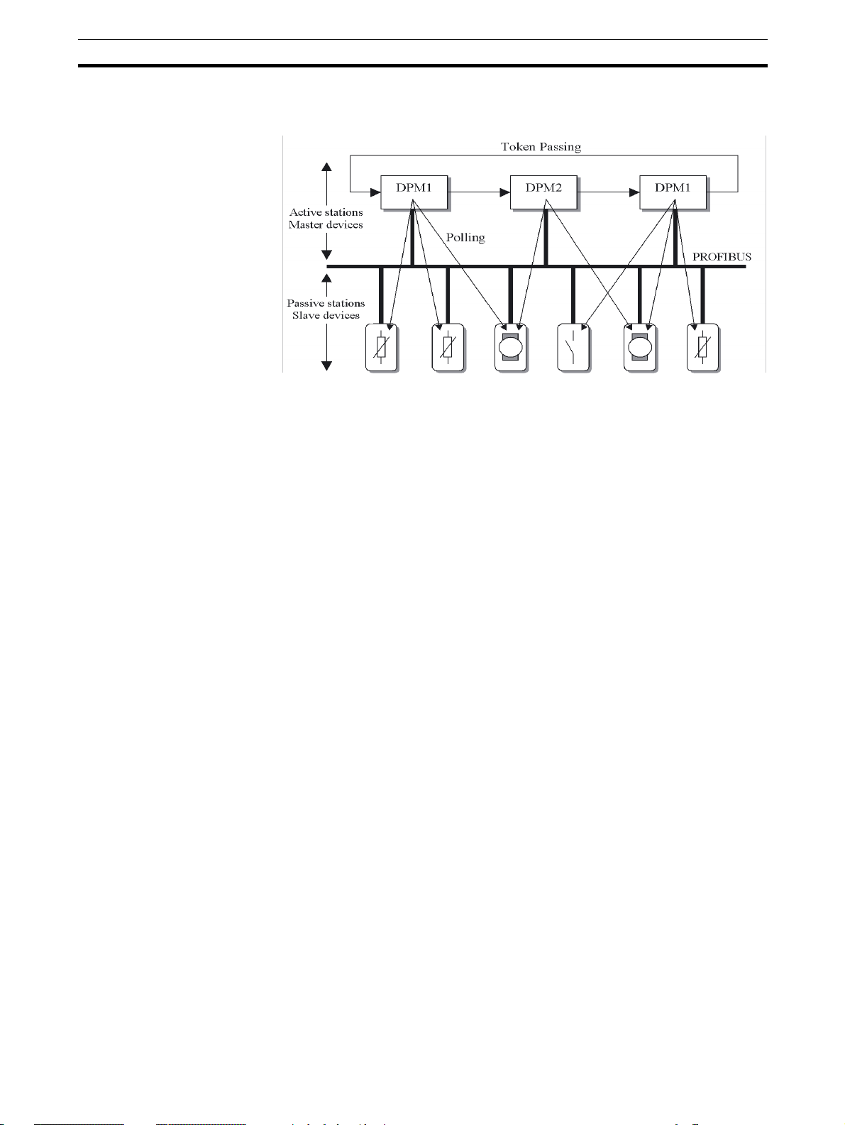
Polling Procedure The polling or master-slave procedure permits the master, currently in pos-
session of the token, to access its assigned slaves. The figure below shows a
possible configuration The configuration shows three active devices (masters)
and six passive devices (slaves).
The three masters form a logical token ring. When an active device receives
the token message, it can perform its master role for a certain period of time.
During this time it can communicate with all assigned slave devices in a mas-
ter-slave communication relationship, and a DPM2 master can take the initia-
5
Overview of PROFIBUS
Section 1-1
tive to communicate with DPM1 master devices in a master-master
communication relationship.
Multi-peer Communication In addition to logical peer-to-peer data transmission, PROFIBUS DP provides
multi-peer communication (broadcast and multicast).
Broadcast
Communication
In the case of broadcast communication a master device sends an unac-
knowledged message to all other devices (masters and slaves).
Multicast Communication In the case of multicast communication a master device sends an un-
acknowledged message to a predetermined group of devices (masters and
slaves).
1-1-5 Diagnostic functions
Extensive Diagnostics Extensive diagnostic functions defined in PROFIBUS DP enable the fast loca-
tion of error at slave devices. Diagnostic messages are transmitted over the
bus and collected at the master. Three levels of diagnostic messages are
defined:
Device Related
Diagnostics
• Messages concerning the general operational status of the whole device,
e.g. over temperature, low voltage.
Module Related
Diagnostics
• Messages indicating that an error is present in a specific I/O range of a
device, e.g. an 8-bit output module.
Channel Related
Diagnostics
• Messages indicating an error at a given input or output, e.g. short circuit
on Output 5.
1-1-6 Protection mechanisms
Monitoring Time PROFIBUS DP provides effective protection functions against parameteriza-
tion errors or failure of the transmission equipment. Time monitoring is pro-
vided both at the master and the slave devices. The monitoring interval is
specified when the system is configured.
Monitoring at the Master The PROFIBUS DP Master monitors data transmission of the slaves with the
Data-Control-Timer. A separate control timer is used for each slave. This
timer expires if response data is not correctly transmitted by the slave within
the monitoring interval. The user is informed when this happens. If the auto-
matic error reaction (Auto-CLEAR) has been enabled, the PROFIBUS DP

6
PROFIBUS DP Network configuration
Section 1-2
master exits its OPERATE state, switches the outputs of all assigned slaves
to the fail-safe status and changes to the CLEAR state.
Monitoring at the Slave Slave devices use a watchdog to detect failures of the master or the bus. If
data communication with the master does not occur within the set watchdog
time interval, a slave automatically switches its outputs to the fail-safe mode.
Also, access protection is provided for the inputs and outputs of the slaves
operating in multi-master systems. Only authorized masters can access their
slaves.
1-1-7 Network Operation Modes
PROFIBUS DP distinguishes four different network operation modes:
OFF-LINE Communication with all PROFIBUS DP participants (masters and slaves) is
stopped. The Master ceases to access the PROFIBUS network.
STOP Communication between the master and its slaves is stopped. Only communi-
cation between the master and other masters is still possible.
CLEAR The master tries to set parameters, check the configuration, and perform data
exchange with its associated slaves. Data exchange involves reading the
inputs of the PROFIBUS DP slaves and writing zeros to the outputs of the
slaves.
OPERATE The master exchanges data with its assigned slaves, inputs are read and out-
puts are written. Also, the master cyclically sends its local status to all its
assigned PROFIBUS DP slaves (using a broadcast message).
Auto-CLEAR
Fail-safe State
If an error occurs during the data exchange phase of the master, the ‘Auto-
CLEAR’ function determines the subsequent actions. If this function has been
disabled, the master remains in the OPERATE mode. If the function has been
enabled, the master automatically changes the network to the CLEAR mode,
in which the outputs of the assigned PROFIBUS DP slaves are switched to
zero, i.e. the ‘fail-safe’ state. The master continues to read the inputs of the
slaves.
1-2 PROFIBUS DP Network configuration
In order to operate a PROFIBUS network, each master in the network needs
to be configured. This process of PROFIBUS Master configuration involves:
• setting up the network topology, i.e. assigning the slave devices with
which the master will be exchanging data,
• defining the parameterization data, which the master will send to each of
the slave devices, before process data exchange can commence
• defining the configuration data, i.e. defining the process data, which will
be exchanged,
• setting up the bus parameters, which define the baud rate and the bus
timing parameters.
• downloading the configuration setup to the master device.
Configuration Technology The configuration process is usually facilitated by a special Computer based
program, often referred to as a Configurator. The Configurator requires spe-
cial configuration files, defining the configuration options for each device,
which is to participate in data exchange. The files must be provided by the
manufacturer of the device.

7
PROFIBUS DP Network configuration
Section 1-2
Two types of configuration technology exist:
• Configuration technology based on FDT/DTM technology
• Configuration technology based on GSD-files
FDT/DTM Concept The FDT/DTM concept specifies the interfaces between the engineering sys-
tems called Field Device Tools (FDT), and the device-specific software com-
ponents called Device Type Managers (DTM).
The FDT/DTM concept separates the device dependent functionality (which is
in the DTM) from the application. It provides separate interfaces for device
configuration, monitoring and maintenance solutions, which before largely
depended on the manufacturer of the application. Because of this concept,
FDT/DTM technology is not limited to PROFIBUS applications. In concept,
any type of network can be configured and accessed, provided the appropri-
ate DTM’s are available.
CX-Profibus is an example of a FDT container application. It is described in
detail in the following sections.
GSD file Technology The older and most commonly used configuration technology is the based on
GSD files (General Slave Data file). A GSD file is a text file, containing the
characteristic features and configuration options of a device. The device data
base file of each device is loaded in the configurator and downloaded to the
master device.
GSD files are usually supplied with a unit, or can be downloaded from the
Internet, either from the manufacturer's site, or from the GSD library of the
PROFIBUS Nutzer Organisation at http://www.profibus.com.
GSD File Language The language used in the GSD file is indicated by the last letter of the file
extension, *.GS?:
Default = GSD
English = GSE
German = GSG
Italian = GSI
Portuguese = GSP
Spanish = GSS
The GSD files are prepared individually by the vendor for each type of device,
according to a fixed format. Some parameters are mandatory, some have a
default value and some are optional. The device data base file is divided into
three parts:
General Section • General specifications
This section contains the vendor name, the device name, hardware- and soft-
ware release versions, device type and identification number, protocol specifi-
cation and supported baud rates.
DP-master Section • DP master-related specifications
This section contains all parameters which only apply to DP master devices
(e.g. maximum memory size for the master parameter set, maximum number
of entries in the list of active devices, or the maximum number of slaves the
master can handle).
DP-slave Section • DP slave-related specifications
This section contains all specification related to slaves (e.g. minimum time
between two slave poll cycles, specification of the inputs and outputs, and
consistency of the I/O data).
8
PROFIBUS DP Gateway
Section 1-3
1-3 PROFIBUS DP Gateway
1-3-1 PROFIBUS DP Gateway Features
PRT1-SCU11 PROFIBUS
DP Gateway
The PRT1-SCU11 is a standalone product, providing an interface between a
PROFIBUS DP Master device and the following OMRON units.
In addition to this functionality, an auxiliary RS-232C interface is provided on
the Unit, to provide a direct connection to a Personal Computer. This direct
connection links the Personal Computer directly to Compoway-F / K-Format /
Memobus protocol, thus bypassing the PROFIBUS DP connection.
Note The PRT1-SCU11 supports only one of the possible protocols at a time. This
means that for example a mix of Compoway-F and Host Link devices is not
supported.
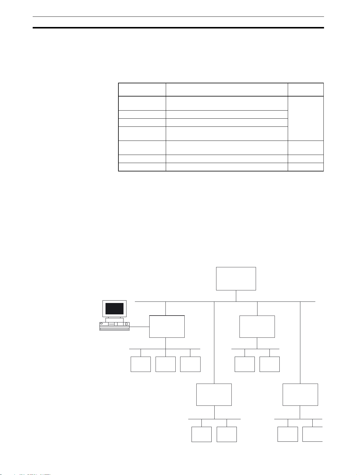
Typical application setup A typical application setup for the PRT1-SCU11 is shown in the figure below.
The PRT1-SCU11 Unit interfaces between PROFIBUS DP and Host Link,
Compoway-F, Memobus and the K-Format protocol.
Unit Description Protocol
supported
E5AN / E5CN /
E5EN / E5GN
OMRON single channel Temperature controllers. Compoway-F
E5ZN OMRON 2-channel Temperature controllers.
E5AR / E5ER OMRON 4-channel Temperature controllers.
E5__ / K3__ /
H8GN
OMRON instruments, supporting OMRON’s RS-
485 based Compoway-F protocol.
E5AK / E5EK OMRON Intelligent Digital Controllers K-Format
protocol
R88A-MCW151-E Option board for W-series servo drives. Host Link
F7 Inverter OMRON-Yaskawa Varispeed F7 Inverter. Memobus
PROFIBUS-DP
Master
PROFIBUS DP network
IBM PS/2
Compoway-F network
(e.g.) E5ZN
PRT1-SCU11
PROFIBUS DP
Gateway
(e.g.) E5_N
(e.g.) E5ER
Host Link network
R88A-
MCW151
R88A-
MCW151
Memobus network
F7 Inverter
F7 Inverter
K-Format network
E5EK
E5AK
PRT1-SCU11
PROFIBUS DP
Gateway
PRT1-SCU11
PROFIBUS DP
Gateway
PRT1-SCU11
PROFIBUS DP
Gateway

9
PROFIBUS DP Gateway
Section 1-3
The PRT1-SCU11 is present on the PROFIBUS DP network as a slave unit.
The interface of the PRT1-SCU11 is controlled by a Master unit on the net-
work. This Master unit can be any PROFIBUS DP class 1 or class 2 master
Compoway-F Compoway-F is the OMRON proprietary serial communication bus system,
based on RS-485, to communicate with a range of OMRON Temperature
Controllers.
K-Format The K-Format protocol is the OMRON proprietary serial communication bus
system, based on either RS-422A or RS-485, to communicate with OMRON’s
E5AK/E5EK Intelligent Digital Controllers.
Host Link Host Link is the OMRON proprietary serial communication bus system, based
on RS-422A, to communicate with the OMRON/Yaskawa R88A-MCW151-E
option board for W-series servo drives.
Memobus The Memobus protocol is the Omron-Yaskawa variation of the Modbus RTU
Protocol used to communicate over either RS-422A or RS-485 with Omron-
Yaskawa F7 Inverters.
IBM compatible Personal
Computer
An IBM compatible Personal Computer is connected to the PRT1-SCU11
PROFIBUS DP Gateway via a RS-232C serial communication to the auxiliary
port. Application programs running on the Personal Computer can communi-
cate through the auxiliary port with Compoway-F, K-Format and Memobus
components, thus bypassing the PROFIBUS DP interface. The Host Link pro-
tocol is not supported by the Auxiliary port.
I/O Data The data exchanged over PROFIBUS DP are word sized, and represent
either fixed length communication blocks or Free Communication blocks. The
PRT1-SCU11 PROFIBUS DP Gateway limits the total number of input words
to 100 words, and the total number of output words to 100 words.
Fixed Communication
Blocks
Fixed Communication Blocks are I/O modules with predefined parameter con-
tent. These modules are to be used to send output and control data to a
device and read status from a device. These I/O modules are defined in the
PRT1-SCU11 and cannot be changed by the user. They are the most com-
monly used and straight forward way to exchange data between a Master and
one or more of the devices attached to the PRT1-SCU11.
In general there are at least two Fixed Communication Blocks defined for
each device type or group of devices attached to a PRT1-SCU11. One block
is always available for limited I/O data, e.g. setpoint and process value, and
one block is available for extended I/O data transfer.
Free Communication
Blocks
Free Communications Blocks, are predefined I/O modules, which allow the
user to send any read, write or operate instruction to any attached Compo-
way-F, K-Format or Memobus device without unit interference. The informa-
tion in the Free Communication Block is used by the PRT1-SCU11 to
assemble the correct message format.
Three types of Free Communication Blocks are defined, the types are Oper-
ate, Read and Write.
• Operate: Execution of a special operation command, which is defined in a
controller.
• Write: Execution of a write data command to any parameter defined in a
controller.
• Read: Execution of a read data command of any parameter defined in a
controller.

10
PROFIBUS DP Gateway
Section 1-3
PROFIBUS I/O Data
Exchange
The PRT1-SCU11 PROFIBUS DP Gateway supports cyclic Master - Slave
communications, i.e. data exchange mode. In data exchange mode the
PRT1-SCU11:
• retrieves all data from the attached units (e.g. Compoway-F) according to
the PROFIBUS configuration and stores this data in the PROFIBUS input
buffer. All input data is obtained before the data is sent to the PROFIBUS
Master as input data.
• writes all data from the PROFIBUS outputs to the attached units accord-
ing to the PROFIBUS configuration, using the proper protocol. Only if the
data received from the Master differs from the current value in the units,
the new output data is sent.
• sends special operation commands.
• sends command data from Free Communication Blocks to the addressed
unit, and returns the command response to the Master as PROFIBUS
input data.
Troubleshooting
Functions
The PRT1-SCU11 is provided with a variety of troubleshooting functions for
prompt recovery in case of errors:
• Extensive self-diagnostic function at startup.
• Diagnostics information is sent to the PROFIBUS Master unit in case:
• One or more units attached to the PRT1-SCU11 has a communication
error.
• The PRT1-SCU11 has a system error.
• Diagnostics flags, indicating if units attached to the PRT1-SCU11 are
functioning correctly. For Host Link there is a communication active bit
that indicates to the Host Link Unit if the received PROFIBUS data is
valid.
1-3-2 Specifications
General Specifications The PRT1-SCU11 is a Gateway between PROFIBUS DP and a range of
OMRON devices, supporting OMRON proprietary protocols. The Unit version
number on the side case of the housing indicates supported protocols. If no
version number is shown, the version number is 1.0. The following table lists
the protocols supported per version number.
PROFIBUS DP Gateway
Model
Note 1. Unit version 2.0 includes the same functions as Unit version 1.0, in addition
to new protocols supported, and it is backward compatible with Unit ver-
sion 1.0. Unit version 2.0 will eventually replace Unit version 1.0.
2. This manual describes all features and functions of Unit version 2.0.
Model name Unit Version Protocol supported
PRT1-SCU11 1.0 Compoway-F
Host Link
2.0 Compoway-F
Host Link
K-Format
Memobus

11
PROFIBUS DP Gateway
Section 1-3
PRT1-SCU11 PROFIBUS DP Gateway Specifications
Item Specification (Unit version 2.0)
Installation
Model PRT1-SCU11
Mounting position DIN rail mounted
Power supply 24 Vdc +10% -15% (20.4 to 26.4 Vdc)
Current consumption 85 mA (max), 75 mA typical at 24 Vdc
Dimensions (W x H x D) 40 x 90 x 65 mm
Weight 130g
Environment
Ambient temperatures Operating temperature: 0 to 55°C
Storage temperature: –20 to 75°C
Ambient operating humidity 10% to 90% (with no condensation)
Vibration resistance Conforms to IEC60068-2-6, test Fc.
10 to 55Hz, 0.25-mm amplitude, 55 to 300Hz, acceleration: 29.4 m/s
2
in X, Y, and Z directions for 120 minutes each.
(Total time: 12 linear sweeps x 10 minutes / sweep = 120 minutes)
Shock resistance Conforms to IEC60068-2-27, test Ea.
196 m/s
2
three times each in X, Y, and Z directions
Dielectric strength 600 VAC (between isolated circuits)
Conformance to EMC and Electrical
safety standards
EN61000-6-2: 2001
EN61000-6-4: 2001/CISPR11
EN61131-2: 2003, IDT
Front case
Settings, rotary switches 2 Slave address rotary switches, range: 0 ~ 99 (Decimal)
Settings DIP-switches 4 DIP-switches on the front of the Unit:
• Switch 1, Switch 2: Baud rate setting RS-422A / RS-485 communi-
cation interface.
• Switch 3: not used.
• Switch 4: auxiliary
RS-232C interface function selector.
Indicators 6 LED’s, indicating Unit status and PROFIBUS status:
Unit status: RUN (Green LED)
ERR (Red LED)
RS-422A/RS-485 protocol: FCOM (Green LED)
FERR (Red LED)
PROFIBUS status: COMM (Green LED)
BF (Red LED)
PROFIBUS Connector 9-pin sub-D female connector (#4/40 UNC thread).
I/O units + data
Number of GSD I/O Units 15.
Number of GSD I/O modules 18, maximum number of modules represent 15 units and 1 read, 1 write
and 1 operation Free Communication Block.
Total sum of all modules must not exceed 18 modules, this includes a
maximum of 15 physical units.
Number of I/O data supported by slave
Unit
Up to 100 words input and 100 words output maximum.
Number of diagnostics data supported
by slave Unit
Up to 7 bytes of diagnostics max. per attached unit.
Diagnostic data is collected at the attached unit, and is part of the
PROFIBUS input/output message.
Extended diagnostics supported by the
slave Unit
The Unit reports system errors and communication errors in a PROFI-
BUS extended diagnostic message, this message has a length of 7
bytes. After detection of a system error, the data exchange is stopped.

12
PROFIBUS DP Gateway
Section 1-3
Protocol Specifications
Item Specification
Protocol port physical layer
Media types • RS-422A, galvanically isolated.
• RS-485, galvanically isolated.
Selection for RS-485 is made with Physical layer switch 1 (see
2-1-3
Switch Settings
).
ON: RS-485
OFF: RS-422A
termination resistor Internal 220 Ohm resistor between receiver lines.
Use of resistor can be enabled or disabled, using Physical layer switch
2 (see
2-1-3 Switch Settings
).
ON: Termination resistor enabled.
OFF: Termination resistor disabled.
Connector 5-pin Phoenix connector
Baud rates supported • 9.6 kbit/s
• 19.2 kbit/s
• 38.4 kbit/s
Selection via DIP-switches 1 and 2. (See
2-1-3 Switch Settings
).
Protocol types supported via this port • Compoway-F
• Host Link
•K-Format
• Memobus
Device address range
1 ~ 15, set through the slot number of the PROFIBUS module configu-
ration. Number 0 (zero) is reserved.
Auxiliary port
Media type RS-232C, located behind cover marked “Peripheral”
Use the CS1W-CN226 connection cable for connecting the PRT1-
SCU11 with Thermotools
Baud rates supported Baud rate used on Auxiliary port is the same as the baud rate used on
the main protocol port.
Selection via DIP-switches 1 and 2. (See
2-1-3 Switch Settings
).
Protocol types supported via this port • Compoway-F
•K-Format
• Memobus
PROFIBUS DP interface
Applicable standards EN50170, Volume 2
Protocol type supported PROFIBUS DP
PROFIBUS Unit type PROFIBUS DP slave
PROFIBUS Media type RS-485, galvanically isolated
PROFIBUS Connector 9-pin sub-D female connector (#4/40 UNC thread)
Termination according to EN50170 provided by the cable connector
Unit device address range
0 ~ 99, set through rotary switches
Remote setting not supported.
Baud rates supported (Auto-detect) • 9.6 kbit/s
• 19.2 kbit/s
• 45.45 kbit/s
• 93.75 kbit/s
• 187 kbit/s
• 500 kbit/s
• 1.5 Mbit/s
•3 Mbit/s
•6 Mbit/s
• 12 Mbit/s
13
PROFIBUS DP Gateway
Section 1-3
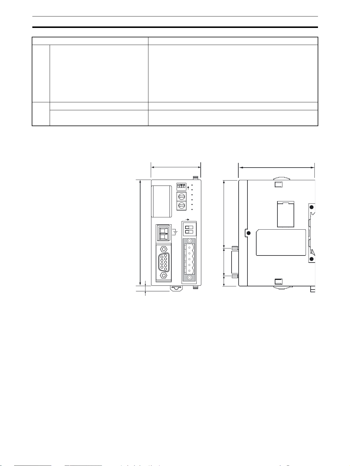
External Dimensions
PROFIBUS services
PROFIBUS services supported • Set_Prm
• Chk_Cfg
• Get_Cfg
• Slave_Diag
• Data_Exchange
• RD_Inp
• RD_Outp
• Global_Control - Sync / Unsync Freeze / Unfreeze/ Clear
I/O Data
Number of I/O data supported Up to 100 words input and 100 words output max.
Number of diagnostics data supported 6 Bytes basic, and 9 bytes extended.
Item Specification
PERIPHERAL
PRT1-SCU11
ON
NODE
ADDRESS
RUN
ERR
COMM
BF
FCOM
FERR
x10
x1
24 Vdc
BUS
ON
1
2
40
90
65
25
57
8
Units: mm
0
23
4
5
6
78
9
1
0
23
4
5
6
78
9
1
1234
R-
R+
S-
S+
FG
5
14
Basic Operating Procedure
Section 1-4
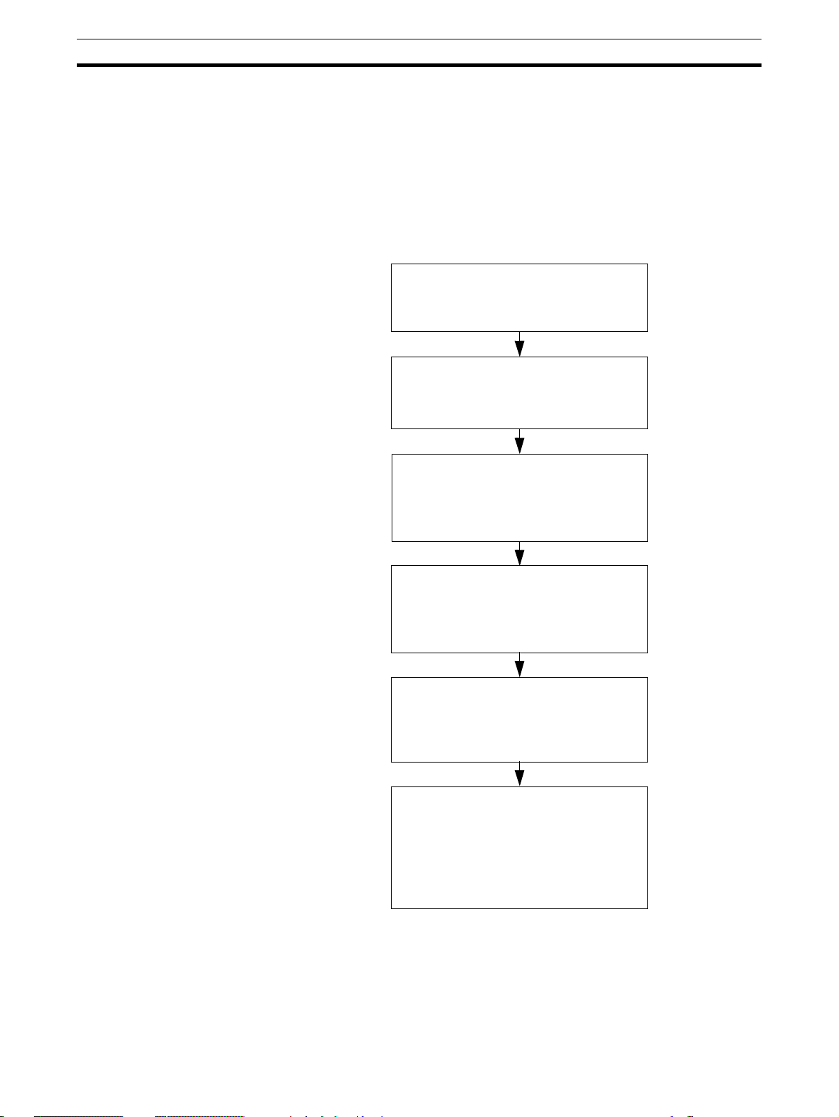
1-4 Basic Operating Procedure
1-4-1 Overview
The following diagram provides an overview of the installation procedures.
For experienced installation engineers, this may provide sufficient informa-
tion. For others, cross-references are made to various sections of this manual
where more explicit information is given. When reading this manual online,
the flow chart entries provide links to the sections containing detailed informa-
tion.
Mount the PRT1-SCU11 on a DIN-rail,
and wire the Unit.
(See section
2-2-2 Mounting the PRT1-
SCU11
)
Select a Device address using the two
rotary switches on the front of the
PRT1-SCU11
(See section
2-1-3 Switch Settings
)
Select a baud rate to be used on the
RS-422A/RS-485 protocol network.
Disable the auxiliary RS-232C port on
the front.
(See section
2-1-3 Switch Settings
)
Connect the I/O Modules Units to the
RS-422A/RS-485 network, and connect
the PRT1-SCU11 to the PROFIBUS
network (See section
2-3 Wiring the
RS-422A / RS-485 Devices
)
Power up the PRT1-SCU11.
Configure the PROFIBUS Master,
using the Master Configuration tool
(See section
2-6 Configuring the
PROFIBUS DP network
).
The PRT1-SCU11 starts exchanging
I/O data between the RS-422A/RS-485
devices and the PROFIBUS Master.
Status is confirmed by the FCOM and
COMM LED indicators.
(See section
2-1-2 LED Indicators
).
Loading...