

Page 1
Cat. No. W900--E2--1
PRT1-COM & GT1 Series
PROFIBUS-DP
MULTIPLE I/O TERMINAL
Page 2

PRT1-COM
GT1 Series
PROFIBUS-DP
MULTIPLE I/O TERMINAL
Operation Manual
Produced December 1999
Page 3

iv
Page 4

Notice:
OMRON products are manufactured for use according to proper procedures by a qualified operator
and only for the purposes described in this manual.
The following conventions are used to indicate and classify precautions in this manual. Always heed
the information provided with them. Failure to heed precautions can result in injury to people or
damage to property.
DANGER
!
WARNING
!
Caution
!
Indicates an imminently hazardous situation which, if not avoided, will result in death or
serious injury.
Indicates a potentially hazardous situation which, if not avoided, could result in death or
serious injury.
Indicates a potentially hazardous situation which, if not avoided, may result in minor or
moderate injury, or property damage.
OMRON Product References
All OMRON products are capitalized in this manual. The word “Unit” is also capitalized when it refers
to an OMRON product, regardless of whether or not it appears in the proper name of the product.
The abbreviation “Ch,” which appears in some displays and on some OMRON products, often means
“word” and is abbreviated “Wd” in documentation in this sense.
The abbreviation “PC” means Programmable Controller and is not used as an abbreviation for
anything else.
Visual Aids
The following headings appear in the left column of the manual to help you locate different types of
information.
Indicates information of particular interest for efficient and convenient operation
Note
of the product.
1, 2, 3... 1. Indicates lists of one sort or another, such as procedures, checklists, etc.
Trademarks and Copyrights
Motorola is a registered trademark of Motorola, Inc.
Intel is a registered trademark of Intel, Inc.
OMRON, 1999
All rights reserved. No part of this publication may be reproduced, stored in a retrieval system, or transmitted, in any
form, or by any means, mechanical, electronic, photocopying, recording, or otherwise, without the prior written permission of OMRON.
No patent liability is assumed with respect to the use of the information contained herein. Moreover, because OMRON is
constantly striving to improve its high-quality products, the information contained in this manual is subject to change
without notice. Every precaution has been taken in the preparation of this manual. Nevertheless, OMRON assumes no
responsibility for errors or omissions. Neither is any liability assumed for damages resulting from the use of the information contained in this publication.
v
Page 5

vi
Page 6

TABLE OF CONTENTS
PRECAUTIONS xi
1 Intended Audience xii...........................................................
2 General Precautions xii..........................................................
3 Safety Precautions xii...........................................................
4 Operating Environment Precautions xii.............................................
5 Application Precautions xiii.......................................................
6 EC Directives xv...............................................................
......................................................
SECTION 1
PROFIBUS-DP 1
1-1 Introduction 2............................................................
1-2 Protocol architecture 3......................................................
1-3 Device types 4............................................................
1-4 PROFIBUS-DP characteristics 5..............................................
1-5 Device Data Base files 8....................................................
1-6 Profiles 9................................................................
........................................................
SECTION 2
Installation of PROFIBUS-DP Network 11..............
2-1 PROFIBUS-DP MULTIPLE I/O TERMINAL 12..................................
2-2 Communication Unit PRT1-COM 13...........................................
2-3 Setting up a PROFIBUS-DP network 18.........................................
SECTION 3
MULTIPLE I/O TERMINAL 23.......................
3-1 MULTIPLE I/O TERMINAL 24...............................................
3-2 Functions 29..............................................................
SECTION 4
Hardware Setup and Operational Check 37.............
4-1 Basic Procedure 38.........................................................
4-2 Specific Example 39........................................................
SECTION 5
Sample Programs 43.................................
5-1 Examples of Counter Unit Operation 44.........................................
SECTION 6
Basic I /O Unit Specifications 51.......................
6-1 Common Specifications for Basic I/O Units 52....................................
6-2 Transistor Input Units 54.....................................................
6-3 Transistor Output Units 74....................................................
6-4 Relay Output Units 97.......................................................
SECTION 7
Special I/O Unit Specifications 103......................
7-1 Analog Input Units 104.......................................................
7-2 Analog Output Units 120......................................................
7-3 Counter Units 134...........................................................
vii
Page 7

TABLE OF CONTENTS
SECTION 8
Communications Timing 151...........................
8-1 Remote I/O Communications Characteristics 152...................................
SECTION 9
Troubleshooting and Maintenance 157...................
9-1 Normal Indication 158........................................................
9-2 Troubleshooting 159.........................................................
9-3 Maintenance 164............................................................
Appendices
A GSD file for PRT1-COM 167.....................................................
B Connectible Devices 171.........................................................
Index 175...........................................
Revision History 177..................................
viii
Page 8

About this Manual:
This manual describes the installation and operation of the PROFIBUS-DP MULTIPLE I/O TERMINAL. A
modular system of I/O units (GT1 Series) connected by a communication unit (PRT1-COM) to
PROFIBUS-DP. The manual includes the sections described below.
Please read this manual carefully and be sure you understand the information provided before
attempt-ing to install and operate the PROFIBUS-DP Communication Unit and Multiple I/O units.
to read the precautions provided in the following section.
Section 1 gives a brief description of PROFIBUS-DP.
Section 2 describes the specification and installation of the PRT1-COM in a PROFIBUS-DP Network.
Section 3 provides an overview of the MULTIPLE I/O TERMINAL, including its features and functions.
Section 4 provides the basic procedure for operation and includes an actual example.
Section 5 provides some examples of programs used with the Counter Unit.
Section 6 provides the specifications for the basic I/O Units, the transistor Input and Output Units, and
Relay Output Units.
Section 7 provides the specifications for Special I/O Units, including the Analog Input and Output Unit,
and the Counter Unit.
Section 8 provides characteristics for communications by the PROFIBUS-DP Communication unit and
describes how to calculate the times required for communication between the various I/O units.
Section 9 describes the troubleshooting procedures and maintenance operations.
Appendix A provides a listing of the PRT1-COM GSD file.
Appendix B provides an overview of connectable devices.
Be sure
!
WARNING
Failure to read and understand the information provided in this manual may result in
personal injury or death, damage to the product, or product failure. Please read each
section in its entirety and be sure you understand the information provided in the section
and related sections before attempting any of the procedures or operations given.
ix
Page 9

x
Page 10

PRECAUTIONS
This section provides general precautions for using the Programmable Controller (PC) Systems and related devices.
The information contained in this section is important for the safe and reliable application of PC Systems. You must
read this section and understand the information contained before attempting to set up or operate a PC System.
1 Intended Audience xii...........................................................
2 General Precautions xii..........................................................
3 Safety Precautions xii...........................................................
4 Operating Environment Precautions xii.............................................
5 Application Precautions xiii.......................................................
6 EC Directives xv...............................................................
xi
Page 11

1 Intended Audience
This manual is intended for the following personnel, who must also have
knowledge of electrical systems (an electrical engineer or the equivalent):
• Personnel in charge of installing FA systems.
• Personnel in charge of designing FA systems.
• Personnel in charge of managing FA systems and facilities.
2 General Precautions
This manual provides information for programming and operating OMRON PC
Systems. Be sure to read this manual before attempting to use the software and
keep this manual close at hand for reference during operation.
The user must operate the product according to the performance specifications
described in the operation manuals.
Before using the product under conditions which are not described in the manual
or applying the product to nuclear control systems, railroad systems, aviation
systems, vehicles, combustion systems, medical equipment, amusement
machines, safety equipment, and other systems, machines, and equipment that
may have a serious influence on lives and property if used improperly, consult
your OMRON representative.
Make sure that the ratings and performance characteristics of the product are
sufficient for the systems, machines, and equipment, and be sure to provide the
systems, machines, and equipment with double safety mechanisms.
4Operating Environment Precautions
WARNING
!
It is extremely important that a PC System and all PC Units be used for the
specified purpose and under the specified conditions, especially in applications
that can directly or indirectly affect human life. You must consult with your
OMRON representative before applying a PC System to the above mentioned
applications.
3 Safety Precautions
WARNING
!
WARNING
!
Never attempt to disassemble any Units while power is being supplied. Doing so
may result in serious electrical shock or electrocution.
Never touch any of the terminals while power is being supplied. Doing so may
result in serious electrical shock or electrocution.
4 Operating Environment Precautions
Do not operate the control system in the following places:
• Locations subject to direct sunlight.
• Locations subject to temperatures or humidity outside the range specified in
the specifications.
• Locations subject to condensation as the result of severe changes in
temperature.
• Locations subject to corrosive or flammable gases.
• Locations subject to dust (especially iron dust) or salts.
• Locations subject to shock or vibration.
• Locations subject to exposure to water, oil, or chemicals.
xii
Page 12

• Take appropriate and sufficient countermeasures when installing systems in
the following locations:
• Locations subject to static electricity or other forms of electrical
interference.
• Locations subject to strong electromagnetic fields.
• Locations subject to possible exposure to radioactivity.
• Locations close to power supplies.
5Application Precautions
Caution
!
The operating environment of the PC System can have a large effect on the
longevity and reliability of the system. Improper operating environments can
lead to malfunction, failure, and other unforeseeable problems with the PC
System. Be sure that the operating environment is within the specified
conditions at installation and remains within the specified conditions during the
life of the system.
5 Application Precautions
Observe the following precautions when using the MULTIPLE I/O TERMINAL.
WARNING
!
Failure to abide by the following precautions could lead to serious or possibly
fatal injury. Always heed these precautions.
• Always ground the system to 100 Ω or less when installing the system to
protect against electrical shock.
• Always turn OFF the power supply to the system before attempting any of the
following. Performing any of the following with the power supply turned ON
may lead to electrical shock:
• Mounting or removing any Units (e.g., I/O Units, CPU Unit, etc.) or memory
cassettes.
• Assembling any devices or racks.
• Connecting or disconnecting any cables, connectors, or wiring.
Caution
!
Failure to abide by the following precautions could lead to faulty operation of or
damage to the MULTIPLE I/O TERMINAL. Always heed these precautions.
• Use the Units only with the power supplies and voltages specified in the
operation manuals. Other power supplies and voltages may damage the
Units.
• Take measures to stabilize the power supply to conform to the rated supply if it
is not stable.
• Provide circuit breakers and other safety measures to provide protection
against shorts in external wiring.
• Do not apply voltages exceeding the rated input voltage to Input Units. The
Input Units may be destroyed.
• Do not apply voltages exceeding the maximum switching capacity to Output
Units. The Output Units may be destroyed.
• Install all Units according to instructions in the operation manuals. Improper
installation may cause faulty operation.
• Be sure to tighten Backplane screws, terminal screws, and cable connector
screws securely.
• Do not attempt to take any Units apart, to repair any Units, or to modify any
Units in any way.
• Do not use communications cables or I/O cables in parallel to or close to
high-tension, high-rate current carrying lines. Doing so may cause faulty
operation
xiii
Page 13

• Be sure to install the MULTIPLE I/O TERMINAL in the proper direction. Not
doing so may cause faulty operation.
• When attaching Units to the DIN rail, be sure to attach them securely. Not doing
so may cause the Units to be damaged.
• Use this product within the specified ranges for communications distances and
connection distances. Not doing so may lead to faulty operation.
• Use the specified cables when making communications connections. Not
doing so may cause faulty operation.
• Be sure to wire the communications paths, the communications power
supplies, the internal power supplies, and the I/O power supplies correctly.
Use voltages for the power supplies that are within the specified ranges. Not
doing so may cause malfunction.
• Do not, under any circumstances, use this product with loads exceeding the
contact rating values. Doing so may cause deterioration of insulation and
damage.
• The life-expectancy of the relays depends greatly on the switching conditions.
Before practical use of the product, perform a trial operation of the product in
the actual conditions in which it will be used. Use the product at a switching
frequency that will allow efficient operation. Continued use of the product in
conditions causing reduced efficiency will cause deterioration of insulation and
damage.
5Application Precautions
• Connection Cables
• Before switching ON power supplies, check that the connectors are
mounted securely.
• Check that the connectors for the I/O Unit interfaces are securely locked.
• Tightening Torques
Check that all the screws for the Units are tightened to the correct torque. Not
doing so may cause faulty operation.
• Internal power supplies, I/O power supplies, terminal screws:
0.3to0.5NS m
• Communications cable, communications connector screws:
0.25 to 0.35 N S m
• High-density I/O Unit connector screws: 0.25 to 0.35 N S m
• Cleaning
• Do not used thinner-based products for cleaning. Doing so may dissolve
attachment areas or cause discoloration.
• Power Supply
• Use separate power supplies for communications power supplies, internal
power supplies, I/O power supplies, load power supplies, and encoder
power supplies. Not doing so may lead to faulty operation.
Caution
!
The following precautions are necessary to ensure the general safety of the
system. Always heed these precautions.
• Provide double safety mechanisms to handle incorrect signals that can be
• Provide external interlock circuits, limit circuits, and other safety circuits in
xiv
generated by broken signal lines or momentary power interruptions.
addition to any provided within the PC System to ensure safety.
Page 14

6 EC Directives
The MULTIPLE I/O TERMINAL conforms to EMC and Low Voltage Directives as
follows:
EMC
Directives
OMRON devices that comply with EC Directives also conform to the related
EMC standards so that they can be more easily built into other devices or the
overall machine. The actual products have been checked for conformity to EMC
standards (see the following note). Whether the products conform to the
standards in the system used by the customer, however,must be checked by the
customer.
EMC-related performance of the OMRON devices that comply with EC
Directives will vary depending on the configuration, wiring, and other conditions
of the equipment or control panel on which the OMRON devices are installed.
The customer must, therefore, perform the final check to confirm that devices
and the overall machine conform to EMC standards.
Low Voltage
Always ensure that devices (Relay Units) operating at voltages of 50 to
1,000 VAC and 75 to 1,500 VDC meet the required safety standards (IEC255).
The MULTIPLE I/O TERMINALS that comply with EC Directives must be
installed as follows:
Directive
6EC Directives
1, 2, 3... 1. MULTIPLE I/O TERMINALS are designed for installation inside control
panels. All MULTIPLE I/O TERMINALS must be installed within control
panels.
2. Used reinforced insulation or double insulation for the DC power supplies
used for the communications power supply, internal circuit power supply,
and the I/O power supplies.
3. MULTIPLE I/O TERMINAL products that meet EC Directives also meet the
Common Emission Standard (EN50081-2). However, radiated emission (at
10 m) will vary with the overall configuration of the control panel, other
devices connected to the control panel, and other conditions. You must
therefore confirm that EC Directives are satisfied for the overall machine or
device.
xv
Page 15

This section gives a brief description of PROFIBUS-DP.
1-1 Introduction 2............................................................
1-2 Protocol architecture 3......................................................
1-3 Device types 4............................................................
1-4 PROFIBUS-DP characteristics 5..............................................
1-4-1 Bus Access Protocol 5...............................................
1-4-2 Data throughput 6..................................................
1-4-3 Diagnostics functions 6..............................................
1-4-4 Protection mechanisms 7.............................................
1-4-5 Network states 7...................................................
1-5 Device Data Base files 8....................................................
1-6 Profiles 9................................................................
SECTION 1
PROFIBUS-DP
1
Page 16

1-1 Introduction
1-1SectionIntroduction
Standard EN50170-2
High speed
Process Automation
Higher level
Uniform bus access
protocol
PROFIBUS (
standard for a wide range of applications in manufacturing, process and building
automation. Vendor independence and openness are guaranteed by the
PROFIBUS standard EN50170-2. With PROFIBUS, devices of different
manufacturers can communicate without special interface adjustments.
The PROFIBUS family consists of three compatible versions:
PROFIBUS-DP
stands forDecentralisedPeriphery. It is optimised for high speed and
DP
low-cost interfacing, especially designed for communication between
automation control systems and distributed I/O at the device level.
PROFIBUS-PA
stands forProcessAutomation. It permits sensors and actuators to be
PA
connected on one common bus line even in intrinsically-safe areas. It permits
data communication and power supply over the bus using 2-wire technology
according to the international standard IEC 1158-2.
PROFIBUS-FMS
stands forFieldbusMessageSpecification. This version is the
FMS
general-purpose solution for communication tasks at a higher level. Powerful
services open up a wide range of applications and provide great flexibility. It can
also be used for extensive and complex communications tasks.
PROFIBUS-DP and PROFIBUS-FMS use the same transmission technology
and a uniform bus access protocol. Thus, both versions can be operated
simultaneously on the same cable. However, FMS field devices cannot be
controlled by DP masters or vice versa.
cessField
Pro
) is a vendor-independent, open fieldbus
Bus
Caution
!
It is not possible to exchange one of these family members by another family
member. This will cause faulty operation.
The remainder of this Operation Manual only describes PROFIBUS-DP.
2
Page 17

1-2 Protocol architecture
NOTDEFINE
D
1-2SectionProtocol architecture
OSI
Layer 1, 2 and user
interface
The PROFIBUS-DP protocol architecture is oriented on the Open System
Interconnection (OSI) reference model in accordance with the international
standard ISO 7498.
DP-Profiles
DP-Extensions
User Interface Layer DP Basic Functions
(7) Application Layer
(6) Presentation Layer
(5) Session Layer
(4) Transport Layer
(3) Network Layer
(2) Data Link Layer Fieldbus Data Link (FDL)
(1) Physical Layer RS-485 / Fibre Optics
OSI layer model of PROFIBUS-DP
PROFIBUS-DP uses layers 1 and 2, and the user interface. Layers 3 to 7 are not
defined.
Layer 1 (physical layer) defines the physical transmission characteristics.
Layer 2 (data link layer) defines the bus access protocol.
This streamlined architecture ensures fast and efficient data transmission. The
application functions which are available to the user, as well as the system and
device behaviour of the various PROFIBUS-DP device types, are specified in
the user interface.
NOT DEFINED
Transmission medium
Easy installation
Cable length
RS-485 transmission technology or fibre optics are defined as transmission
medium. RS-485 transmission is the most frequently used transmission
technology. Its application area includes all areas in which high transmission
speed and simple inexpensive installation are required. Twisted pair shielded
copper cable with one conductor pair is used.
The RS-485 transmission technology is very easy to handle. Installation of the
twisted pair cable does not require expert knowledge. The bus structure permits
addition and removal of stations or step-by-step commissioning of the system
without influencing the other stations. Later expansions have no effect on
stations which are already in operation.
Various transmission speeds between 9.6 kbit/s and 12 Mbit/s can be selected.
One unique transmission speed is selected for all devices on the bus when the
system is commissioned.
The maximum cable length depends on the transmission speed (see section
2-3-1). The length can be increased by the use of repeaters. The use of more
than 3 repeaters in series is not recommended.
3
Page 18

1-3 Device types
1-3SectionDevice types
PROFIBUS-DP distinguishes between master devices and slave devices.
Master devices
DPM1, DPM2
Slave devices
Master devices control the data communication on the bus. PROFIBUS-DP
allows more then one master in the network. A master can send messages
without an external request, as long as it holds the bus access right (the token).
Masters are also called active stations in the PROFIBUS-DP standard.
There are two types of master devices: DP master class 1 (DPM1) and DP
master class 2 (DPM2).
A DPM1 is a central controller, which exchanges information with the
decentralised stations (i.e. DP slaves) within a specified message cycle.
DPM2 devices are programmers, configuration devices or operator panels.
They are used during commissioning for configuration of the DP system or for
operation and monitoring purposes.
Slave devices are peripheral devices. Typical slave devices include input/output
devices, valves, drives and measuring transmitters. They do not have bus
access rights and they can only acknowledge received messages or send
messages to the master when requested to do so. Slaves are also called
passive stations.
The PRT1-COM is a modular slave device.
4
Page 19
1-4 PROFIBUS-DP characteristics
1-4-1 Bus Access Protocol
1-4SectionPROFIBUS-DP characteristics
Layer 2
Medium Access Control
T oken passing
Polling procedure
The bus access protocol is defined by layer 2. This protocol also includes data
security and the handling of the transmission protocols and messages.
The Medium Access Control (MAC) specifies the procedures, which determine
when a station is permitted to transmit data. A token passing procedure is used
to handle the bus access between master devices, and a polling procedure is
used to handle the communication between a master device and its assigned
slave device(s).
The token passing procedure guarantees that the bus access right (the token) is
assigned to each master within a precisely defined time frame. The token
message, a special message for passing access rights from one master to the
next master, must be passed around the logical token ring - once to each master
- within a specified target rotation time.
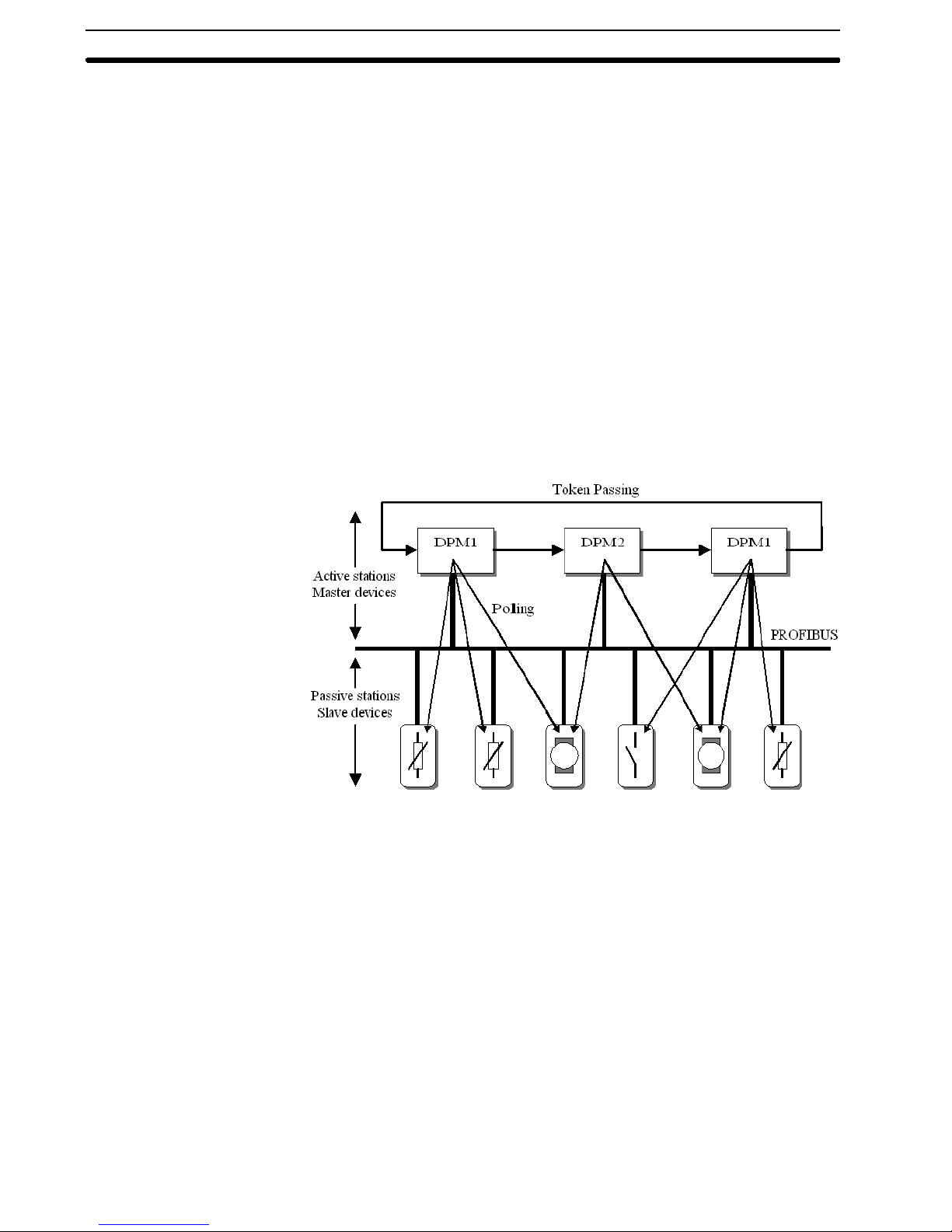
The polling or master-slave procedure permits the master, which currently owns
the token, to access its assigned slaves. The picture below shows a possible
configuration.
Token passing and Slave polling mechanisms
The configuration shows three active stations (masters) and six passive stations
(slaves).
The three masters form a logical token ring. When an active station receives the
token message, it can perform its master role for a certain period of time. During
this time it can communicate with all assigned slave stations in a master-slave
communication relationship. In addition a DPM2 master can take the initiative to
communicate with DPM1 master stations in a master-master communication
relationship.
Multi-peer
communication
In addition to logical peer-to-peer data transmission, PROFIBUS-DP provides
multi-peer communication (broadcast and multicast).
Broadcast communication: an active station sends an unacknowledged
Multicast communication: an active station sends an unacknowledged
message to all other stations (master and slaves).
message to a predetermined group of stations
(master and slaves).
5
Page 20
1-4-2 Data throughput
1-4SectionPROFIBUS-DP characteristics
Transmission time
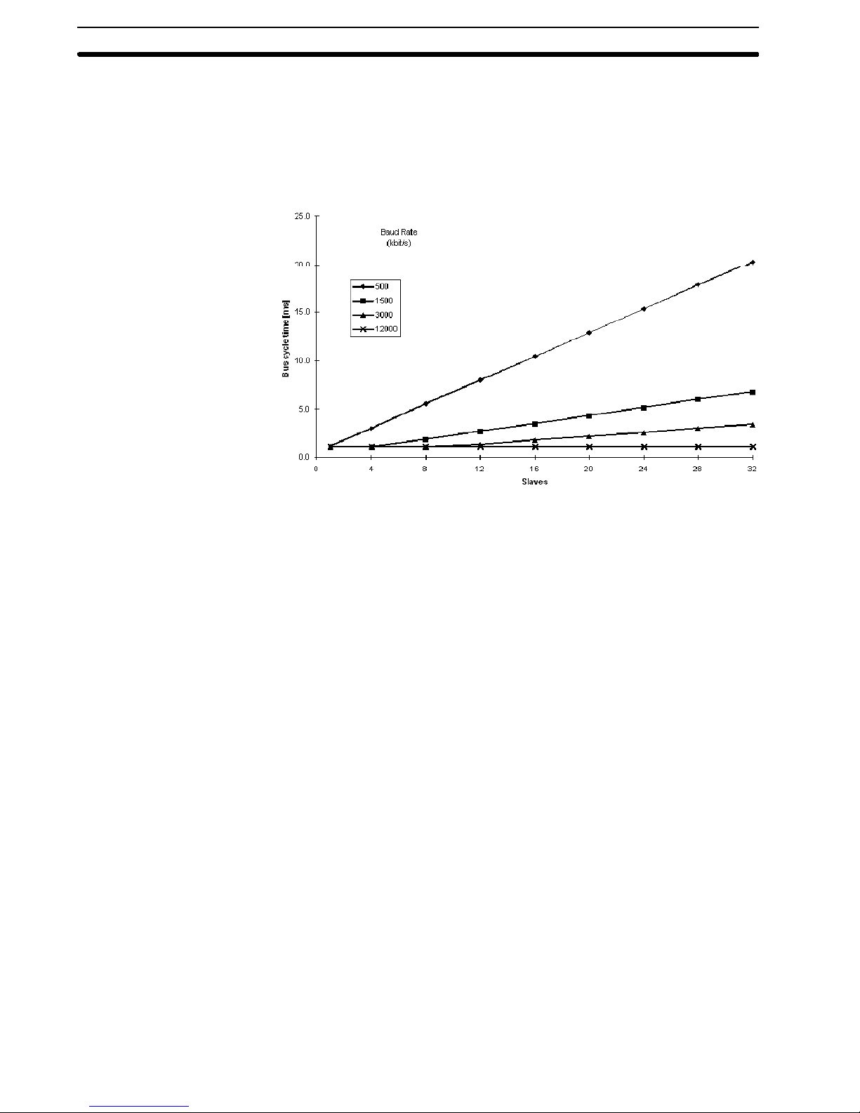
At 12 Mbit/s, PROFIBUS-DP requires approximately 1 ms for the transmission
of 512 bits of input data and 512 bits of output data distributed over 32 stations.
The figure below shows the typical PROFIBUS-DP transmission time
depending on the number of stations and the transmission speed. The data
throughput will decrease when more than one master is used.
Bus cycle time vs number of slaves
Conditions: Each slave has 2 bytes of input data and 2 bytes of output data.
1-4-3 Diagnostics functions
Extensive diagnostics
Device related
diagnostics
Module related
diagnostics
Channel related
diagnostics
The extensive diagnostic functions of PROFIBUS-DP enable fast location of
faults. The diagnostic messages are transmitted over the bus and collected at
the master. These messages are divided into three levels:
• Device related diagnostics
This diagnostic level concerns the general operational status of the whole
device (e.g. overtemperature or low voltage).
• Module related diagnostics
This diagnostic level indicates that a fault is present in a specific I/O range
(e.g. an 8-bit output module) of a station.
• Channel related diagnostics
This diagnostic level indicates an error at an individual input or output (e.g.
short circuit on output 5).
6
Page 21

1-4-4 Protection mechanisms
1-4SectionDevice types
Time monitoring
At the master
At the slave
PROFIBUS-DP provides effective protection functions against
parameterisation errors or failure of the transmission equipment. Time
monitoring is provided at the DP master and at the DP slaves. The monitoring
interval is specified during the configuration.
• Protection mechanism at the master.
The DPM1 master monitors data transmission of its active slaves with the
Data_Control_Timer. A separate control timer is used for each slave. This
timer expires, when correct data transmission does not occur within the
monitoring interval.
If the master’s Auto_Clear Mode has been enabled, the DPM1 will exit its
Operate state, switches the outputs of all assigned slaves to fail-safe status
and changes to its Clear status (see also section 1-4-5).
• Protection mechanisms at the slave.
The slave uses the watchdog control to detect failures of the master or the
transmission line. If no data communication with the master occurs within the
watchdog control interval, the slave automatically switches its outputs to the
fail-safe status. This mechanism can be enabled or disabled for each
individual slave.
Also, access protection is available for the inputs and outputs of the DP
slaves operating in multi-master systems. This ensures that direct access
can only be performed by the authorised master. For all other masters, the
slaves offer an image of their inputs and outputs, which can be read from any
master, even without access rights.
1-4-5 Network states
Off-line
Stop
Clear
Operate
Auto_clear
PROFIBUS-DP distinguishes four different network states.
• Off-line
Communication between all PROFIBUS-DP devices on a network is
stopped.
• Stop
Communication between DPM1 and DP slaves is stopped. Only
communication between DPM1 and DPM2 is possible.
• Clear
DPM1 master attempts to set parameters, check the configuration, and
subsequently perform data exchange with its associated DP-slaves. The
data exchange comprises reading the inputs of the DP-slaves and writing
zeros to the outputs of the DP-slaves.
• Operate
DPM1 master exchanges data with its assigned slaves, inputs are read and
outputs are written. Beside this, the DPM1 cyclically sends its local status to
all assigned DP slaves (using a multicast message) at a configurable time
interval.
When an error occurs during the data exchange phase of the DPM1, the
’Auto_clear’ configuration parameter determines the subsequent actions. If this
parameter is set to false, the DPM1 remains in the Operate state. If set to true,
the DPM1 switches the outputs of all assigned DP slaves to the fail-safe state
and the network state changes to the Clear state.
7
Page 22

1-5 Device Data Base files
1-5SectionDevice Data Base files
Plug-and-play
DDB-file, GSD-file
General section
DP-master section
DP-slave section
Configurator
To achieve simple plug-and-play configuration of the PROFIBUS-DP network,
the characteristic features of a device are specified in a file. This file is called a
DDB-file (Device Data Base file) or a GSD-file (Gerätestammdaten file). The
GSD files are prepared individually by the vendor for each type of device,
according a fixed format. Some parameters are mandatory, some have a default
value and some are optional.
The device data base file is divided into three parts:
• General specifications
This section contains vendor and device names, hardware and software
release versions, station type and identification number, protocol
specification and the baud rates supported.
• DP master-related specifications
This section contains all parameters, which only apply to DP master devices
(e.g. maximum memory size for master parameter set, maximum number of
entries in the list of active stations or the maximum number of slaves the
master can handle).
• DP slave-related specifications
This section contains all specifications related to slaves (e.g. minimum time
between two slave poll cycles, specification of the inputs and outputs and
consistency of the I/O data).
The device data base file of each device is loaded in the configurator and
downloaded to the master device.
Refer to the Operation Manual of the PROFIBUS-DP Master Unit (W349) for
usage of the GSD file in the master’s configuration software.
8
Page 23

1-6 Profiles
1-6SectionProfiles
Exchanging devices
To enable the exchange of devices from different vendors, the user data has to
have the same format. The PROFIBUS-DP protocol does not define the format
of user data, it is only responsible for the transmission of this data.
The format of user data may be defined in so called profiles. Profiles can reduce
engineering costs since the meaning of application-related parameters is
specified precisely. Profiles have been defined for specific areas like drive
technology, encoders, and for sensors / actuators.
9
Page 24

Installation of PROFIBUS-DP Network
This section describes the installation of the PRT1-COM within the PROFIBUS-DP Network
2-1 PROFIBUS-DP MULTIPLE IO TERMINAL 12..................................
2-2 Communication Unit PRT1-COM 13...........................................
2-2-1 Specification of PRT1-COM 13........................................
2-2-2 PRT1-COM Components 14...........................................
2-3 Setting up a PROFIBUS-DP network 18.........................................
2-3-1 Fieldbus cabling 18..................................................
2-3-2 Configuring PROFIBUS-DP system 20..................................
SECTION 2
11
Page 25

2-1 PROFIBUS-DP MULTIPLE I/O TERMINAL
The PROFIBUS-DP MULTIPLE I/O TERMINAL is a system with a
communication Unit and various MULTIPLE I/O Units.
The communication Unit (PRT1-COM) connects the MULTIPLE I/O Units to the
PROFIBUS-DP Network. A maximum of eight MULTIPLE I/O Units can be
connected to one PRT1-COM.
The PRT1-COM Unit is described in this section, the total MULTIPLE I/O
TERMINAL system is described in the next section.
2-1SectionPROFIBUS-DP M ULTIPLE I/O TERMINAL
12
Page 26
2-2 Communication Unit PRT1-COM
p
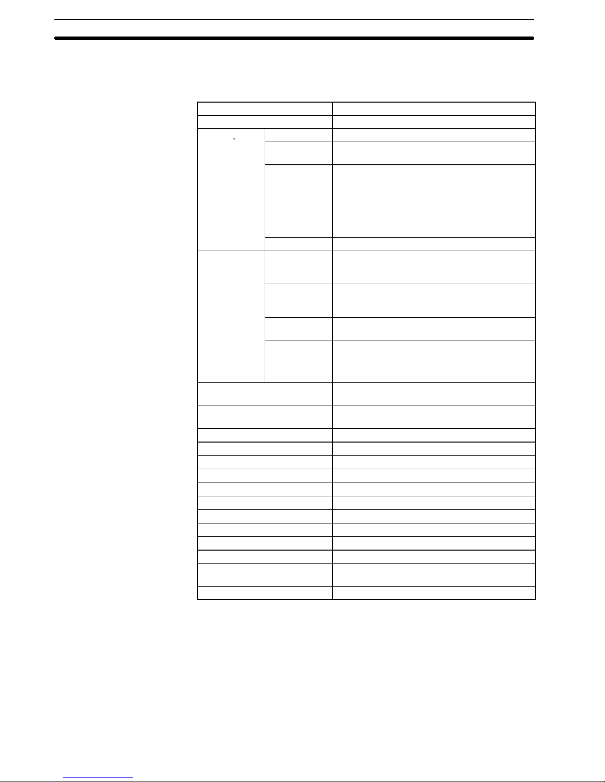
2-2-1 Specification of PRT1-COM
Item Specification
Model PRT1-COM
Internal power
supply
I/O Unit
interface
Noise immunity 1,500 V p-p Pulse width: 0.1 to 1 ms, Pulse rise
Vibration resistance 10 to 150 Hz, 1.0-mm double amplitude or 70
Shock resistance 200 m/s
Dielectric strength 500 VAC (between isolated circuits)
Ambient temperature -10 °Cto55°C
Ambient humidity 25% to 85% (with no condensation)
Operating atmosphere No corrosive gases
Storage temperature -25 °Cto65°C
EMC directives EN50081-2, EN50082-2
Mounting DIN 35-mm rail
Mounting strength 100 N
Terminal strength 100 N
I/O Unit interface connector lock
strength
Weight Approx. 165 g
Voltage range 24VDC +10% - 15% (20.4 to 26.4 VDC)
Unit current
consumption
Maximum
current
Inrush current 30 A max.
Number of
Units
connected
Total number
of inputs /
outputs
Rated output
Current
Overcurrent
Protection
function.
2-2SectionCommunication Unit PRT1-COM
0.18 A max. (at 24 VDC)
0.6 A (with maximum output to I/O Unit) the
capacity required for the internal power supply of
the Communication Unit can be obtained using
the following formula: Communication Unit
internal power supply current = Communication
Unit internal current consumption + total current
Consumption for the I/O Unit interfaces.
8Unitsmax.
Total inputs (IN): 128 bytes max.
Total outputs (OUT): 128 bytes max.
0.3 A max.
105% of rated current or higher. When an
over-current occurs, the power supply to the I/O
Units will remain OFF until the PRT1-COM power
supply is turned OFF and ON again.
time: 1 ns (via noise simulator)
2
m/s
2
50 N
13
Page 27
Characteristics of
PROFIBUS-DP
Applicable standard EN 50170 vol. 2
Type PROFIBUS-DP SLAVE
Bus connector 9-pin sub-D female
Bus termination Not included
Baud rates
(Auto--detect)
PROFIBUS address range 0to125
Communication cable Type A (EN 50170-2)
Minimum slave interval time 1ms
Input data 4 status bytes + max. 128 data bytes
Output data max. 128 data bytes
Supported PROFIBUS-DP functions
9.6 k, 19.2 k, 45.45 k, 93.75 k, 187.5 k,
500 k, 1.5 M, 3 M, 6 M, 12 M bits/s
• Data_Exchange
• Slave_Diag
• Set_Prm
• Chk_Cfg
• Global Control
(SYNC, FREEZE, CLEAR)
• Get_Cfg
• RD_Inp
• RD_Outp
PROFIBUS-DP GSD file OC_047D.GSD
2-2SectionCommunication Unit PRT1-COM
This product has been tested in the test laboratory of PNO (PROFIBUS
Note
Nutzerorganisation) and has been approved as conforming to the
PROFIBUS-DP standard. (EN 50170-2)
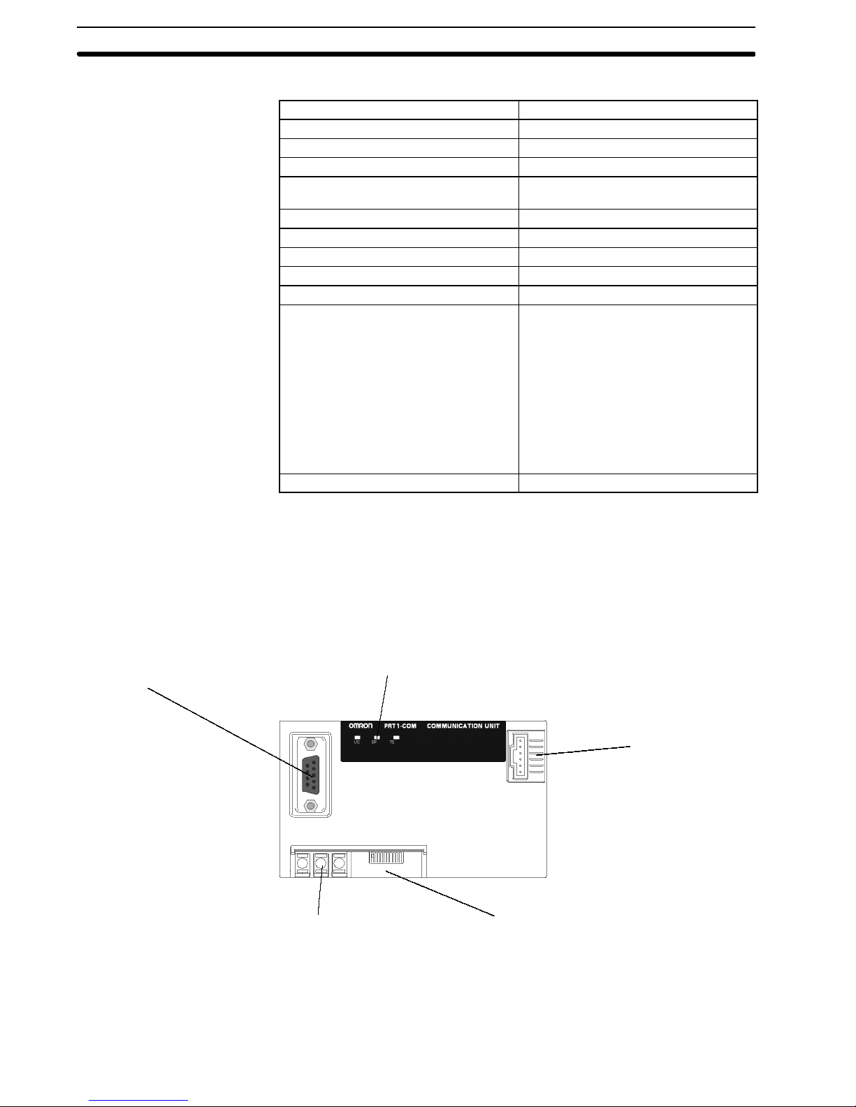
2-2-2 PRT1-COM Components
The following overview shows the various components of PRT1-COM.
PROFIBUS-DP
Communication connector
Power Terminals
LED Indicators
MULTIPLE I/O Unit
Interface connector
DIP Switches
Power Terminals
MULTIPLE I/O Unit
Connect to the power supply for operation and connect to the functional earth.
Connects to the MULTIPLE I/O Unit communication cable.
interface
14
Page 28
2-2SectionCommunication Unit PRT1-COM
(multipleI/O
)
Led Indicators
PRT1-COM has 3 LEDs to indicate the status of the Unit.
1. The Unit specific status is indicated with the US-LED
2. The BF-LED indicates the status of PROFIBUS-DP
3. The MULTIPLE I/O Bus status is indicated with the TS-LED
US LED Colour Description
Unit Status Bicolor
BF LED Color Description
Bus Failure
(Profibus-DP)
TS LED Color Description
Terminal
Status
Green / Red
Red
Bicolor
Green / Red
OFF PWR not OK
Green ON Unit OK
Green BLINK Initialising
Red ON Unit error
OFF No errors
ON
OFF Power overload
Green ON Communication OK
Green BLINK Special I/O Unit Error
Red ON
S Response monitoring time has
elapsed. The master did not
address PRT1-COM within
the configured watchdog time.
S PRT1-COM was not
parameterised or not properly
configured on start-up.
S Bus error
S Configuration error
S End station error
S Max. I/O Unit over
S Basic I/O Unit Error
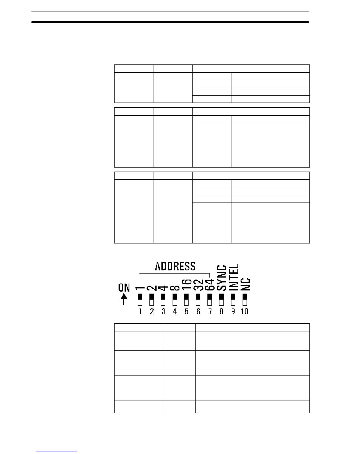
DIP Switch Settings
Switch Name Purpose
1to7 ADDRESS PROFIBUS-DP station address
All OFF = station address 0, (default, see Note)
All ON = station address 127
8 SYNC Data exchange method: Synchronous /
Asynchronous
OFF = Asynchronous, (default)
ON = Synchronous
9 INTEL Double byte transfer method:
INTEL / Motorola
OFF = Motorola, (default)
ON = Intel
10 NC Reserved for system use.
Always off
PROFIBUS-DP address setting is default set to 0.
15
Page 29
2-2SectionCommunication Unit PRT1-COM
– This setting should always be changed to appropriate value.
– Station addresses 126 and 127 are invalid and should not be used.
-- Do not use station address 0 in combination with the C200HW-PRM21
PROFIBUS-DP Master.
Data exchange method
Double byte transfer
method
1. Asynchronous mode:
The MULTIPLE I/O Bus transmit/receive cycles are independent of the
messages being transmitted/received at the PROFIBUS-DP interface.
2. Synchronous mode:
A MULTIPLE I/O Bus transmit/receive cycle will only be initiated if new data
has been received at the PROFIBUS-DP interface.
More information can be found in: section 8-1-4.
Synchronous mode has no meaning when only input MULTIPLE I/O Units are
Note
attached. In this case the switch setting is ignored and asynchronous mode is
used.
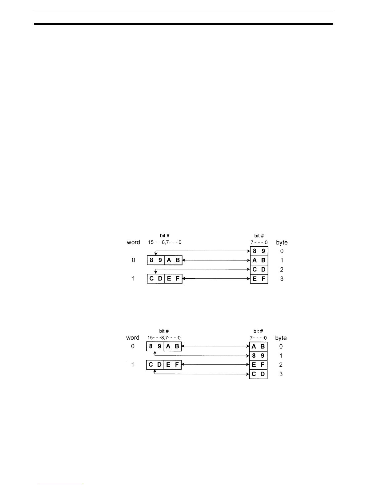
The INTEL switch is used for selection of the little-endian/big-endian mode, to
define the transfer method for double-byte data transfer between
PROFIBUS-DP and MULTIPLE I/O Bus.
This allows for adjustment of the data format if required by the PROFIBUS-DP
master.
1. Big-endian mode (Often referred to as Motorola mode):
The first byte transmitted over PROFIBUS-DP is the most-significant byte
whereas the second byte is the least-significant byte.
MULTIPLE I/O Bus
PROFIBUS-DP message
Mounting
I/O Unit Bus Connectors
16
2. Little-endian mode (Often referred to as Intel mode):
The first byte transmitted over PROFIBUS-DP is the least-significant byte
whereas the second byte is the most-significant byte.
MULTIPLE I/O Bus PROFIBUS-DP message
Changing the transfer method to ’Little-endian’ mode will also have impact on
Note
the transfer of the status bytes, see also section 3-2-4.
Mount the Unit on DIN 35-mm rail using the DIN Track Mounting Hook.
The I/O Unit Bus connectors on the MULTIPLE I/O Units must be connected with
the appropriate cables to provide I/O Unit interface and allow power to be
supplied to the I/O Units.
An End connector cable must be connected to the right-side connector of the last
I/O Unit (terminator).
Page 30
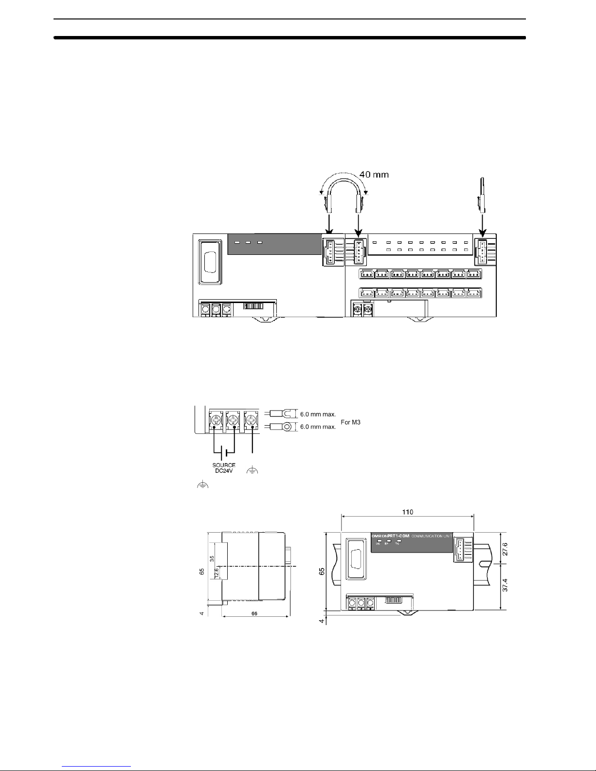
2-2SectionCommunication Unit PRT1-COM
One I/O Unit connecting cable (cable length 40 mm) is included with each I/O
Unit. One End connector is supplied with the Communication Unit. An I/O Unit
connecting cable with a cable length of 1 m (GCN1-100) is sold separately.
Connect the I/O Unit connecting cable to the right connector on the
Communication Unit and to the left connector of the I/O Unit as shown in the
following figure.
Wiring
I/O Unit Connecting Cable
(included with the I/O Unit)
End connector
(included with the
Communication Unit)
Be sure to connect the End connector to the right I/O Unit Bus connector of the
last I/O Unit.
Provide the internal power supply as shown in the following diagram.
Dimensions
Side view Front view
is connected to the shield of the PROFIBUS-DP connector.
17
Page 31

2-3 Setting up a PROFIBUS-DP network
2-3-1 Fieldbus cabling
2-3SectionSetting up a PROFIBUS-DP network
Bus structure
Cable type
Cable
All PROFIBUS-DP devices are connected in a line structure. Each RS485 bus
segment may contain up to 32 stations (masters, slaves, repeaters). When more
than 32 stations are required, repeaters must be used to link the individual bus
segments. The bus must be terminated at the beginning and at the end of each
segment.
The standard EN50170-2 specifies the use of shielded twisted pair cables with
the following parameters (PROFIBUS-DP line type A):
PROFIBUS-DP Cable parameters
Parameter Value
Impedance 135 to 165 Ω (3~20 MHz)
Capacitance per unit length <30pF/m
Loop resistance <110Ω/km
Core diameter >0.64mm
Core cross section >0.34mm2(22 AWG)
The PROFIBUS-DP User Group recommends the following colour coding for
the data signal lines:
A-line - green
B-line - red
Maximum length
Stub lines
Fieldbus connector
The maximum length of the cable depends on the transmission speed. The
cable lengths specified in the table below are based on the above cable
specifications.
Cable length vs. Baud rate
Baud rate (kbit/s) length/segment (m)
9.6, 19.2, 45.45, 93.75 1200
187.5 1000
500 400
1500 200
3000, 6000, 12000 100
Stub lines should be avoided for data transmission speeds of more than 500 kbit/s.
Plug connectors available on the market permit the incoming data cable and the
outgoing data cable to be connected directly in the plug connector. This means
that stub lines do not have to be used, and the bus plug connector can be
connected and disconnected at all times without interrupting data
communication with the other stations.
The connector plug to connect to the PRT1-COM is a 9-pin male sub-D
connector, preferably with a metal case, conducting screws and a solder lip for
connecting the shield of the cable. The cable should at least be connected to pin
3 (B-line) and pin 8 (A-line) of the connector.
18
Page 32

At baud rates over 1.5 Mbit/s, always use
special PROFIBUS-DP connectors with
built-in series inductances, to ensure that
cable reflections caused by the
capacitive load of each unit are
minimised.
Connectors with built-in inductors and
termination resistors, as shown here, are
available from various manufacturers
.
PROFIBUS-DP Connector
Pin No. Signal Description
1 Shield Shield / protective ground
2 – –
3 B-line Data signal
4 RTS Direction control signal for repeaters (TTL)
5 DGND Data ground for terminator resistance (0 Vdc)
6 VP Supply voltage for terminator resistance (+5Vdc)
7 – –
8 A-line Data signal
9 – –
Case Shield Protective ground
2-3SectionSetting up a PROFIBUS-DP network
PROFIBUS-DP Connector with
built-in inductors and
termination
RTS
VP, DGND
Shielding
The signal RTS (TTL signal relative to DGND) is meant for the direction control
of repeaters in case repeaters without self control capability are used.
The signals VP and DGND are meant to power
an externally mounted bus terminator (see
figure). The powering of the 220 Ω termination
resistor ensures a defined idle state potential
on the data lines. To ensure proper functioning
up to the highest baud rate, the bus cable has
to be terminated at both ends of the cable.
PROFIBUS-DP Termination
To ensure electro-magnetic compatibility (EMC), the shield of the cable should
be connected to the metal case and to pin 1 of the connector.
If the Unit is installed within a control cabinet, the cable shield of the incoming
bus cable should be electrically connected to a grounding rail as close as
possible to the cable lead-through using a shield grounding clamp or similar.The
cable shield should continue within the cabinet to the fieldbus device and be
connected there in accordance with the manufacturers instructions.
Ensure that the PLC and the control cabinet in which the device is mounted have
the same ground potential by providing a large-area metallic contact to ground
(use e.g. galvanised steel to ensure a good connection). Grounding rails should
not be attached to painted surfaces.
19
Page 33

2-3SectionSetting up a PROFIBUS-DP network
If the above measures are observed, electro-magnetic interference is diverted
through the cable’s shield.
You may find further information about
• Commissioning of PROFIBUS-DP equipment
• Testing the PROFIBUS-DP cable and bus connectors
• Determining the loop resistance
• Testing for correct bus termination
• Determining the segment length and cable route
• Other test methods
• Example of an equipment report
in the PROFIBUS-DP guideline ”Installation Guideline for PROFIBUS-DP/FMS”
(PNO Order No- 2.112), which is available at every regional PROFIBUS-DP
User Organisation.
Repeaters
The maximum communication distance can be increased by the use of
repeaters. The repeater must be included in the count of the number of stations
per segment. Even though repeaters do not have a node address, they
represent an electrical load on the bus segment like any master or slave station.
If a repeater is located at the end of a bus segment, it should provide bus
termination as well.
It is recommended to limit the number of repeaters in series between any two
stations in the system to a maximum of three units, as shown in the following
example (3 repeaters are encountered in communication between section 6 and
sections 1, 2 and 4).
Example of a PROFIBUS system using repeaters
2-3-2 Configuring PROFIBUS-DP system
After making the physical connections of the network, the PROFIBUS-DP
system needs to be configured. For each master and its assigned slaves, a
configuration has to be defined using a dedicated configuration program.
20
Page 34

2-3SectionSetting up a PROFIBUS-DP network
Configurator
C200HW-PRM21
GSD file
Example
Limits defined
by GSD file
List of available
I/O Units type
The configurator provides the master with information about:
• The slaves that are connected to the master.
• The assignment of slaves to groups for broadcast / multicast messages.
• The mapping of the slaves into the memory of the master.
• The bus parameters (e.g. baud rate, target rotation time etc.).
For more details about the configurator for the C200HW-PRM21 Master Unit,
refer to OMRON Catalog No. W349-E1.
To configure a master Unit to communicate with the PRT1-COM together with
the MULTIPLE I/O Units, the PRT1-COM device database file OC_047D.GSD is
required. Based on the contents of this file, the configuration program for the
master Unit will allow the user to select the MULTIPLE I/O Units.
The example below shows a configuration screen of the PRT1-COM. Here the
PRT1-COM is configured as a slave with 5 MULTIPE I/O Units.
The terms input and output are to be interpreted as seen from the
PROFIBUS-DP master unit.
List of selected
I/O Units
Calculated total
sizes
Check configuration
PRT1-COM Configuration example
The System status module is mandatory. It is required for the PRT1-COM, and
Note
shall always be returned to the master, no matter how many I/O Units have been
connected. It
be selected as the first “I/O Unit”.
must
The list of selected I/O Units should exactly match the attached MULTIPLE I/O
Units. The first I/O Unit (in the example specified in the second row: GT1-ID16-1)
should be placed next to the PRT1-COM. The consecutive selected I/O Units
should be physically placed in this order from left to right. The last I/O Unit
(example: GT1-CT01) should be placed at the right end. This I/O Unit requires
the End connector.
Upon startup of the PROFIBUS-DP communication, the master will send a
Chk_Cfg message so that PRT1-COM can verify that the master’s expected I/O
configuration for the PRT1-COM is correct.
On power-up PRT1-COM determines an I/O table of the attached I/O Units. The
I/O table is compared with the I/O configuration by:
– Amount of I/O bytes per I/O Unit
21
Page 35

2-3SectionSetting up a PROFIBUS-DP network
– Consistency per I/O Unit
– Order of I/O Units (physical position)
If it does not match completely, PRT1-COM will give a negative response to the
PROFIBUS-DP master and will not exchange I/O data.
Re-use the configurator program again to match the selected I/O Units with the
physically attached I/O Units in case the configuration is changed.
22
Page 36

SECTION 3
MULTIPLE I/O TERMINAL
This section provides an overview of the MULTIPLE I/O TERMINAL, including its features and functions.
3-1 MULTIPLE I/O TERMINAL 24...............................................
3-1-1 Overview 24.......................................................
3-1-2 System Configuration 24..............................................
3-1-3 Features 24........................................................
3-1-4 Communication Units and I/O Units 25..................................
3-1-5 List of Models 26...................................................
3-2 Functions 29..............................................................
3-2-1 I/O Unit Interface Specifications 29.....................................
3-2-2 Exchanging Data 31.................................................
3-2-3 Allocating I/O 32....................................................
3-2-4 I/O Unit Interface Status 33............................................
3-2-5 I/O Configuration Changes 35..........................................
23
Page 37

3-1 MULTIPLE I/O TERMINAL
3-1-1 Overview
A MULTIPLE I/O TERMINAL is a modular PROFIBUS-DP Slave that consists of
a Communication Unit providing an interface to one or more I/O Units. The I/O
Unit interface supports up to 8 I/O Units and a total of up to 128 byte input + 128
byte output. I/O Units are connected using simple connections via I/O Unit
Connecting Cables. Allocation and address settings on the I/O Unit interface are
not required, enabling simple, flexible distributed I/O control.
3-1-2 System Configuration
3-1SectionMULTIPLE I/O TERMINAL
3-1-3 Features
Simple Connections
Status Notification
Many Types of I/O Unit
Total number of input bytes: 128. Total number of output bytes: 128
The Communication Unit and the I/O Units are separate, and the
Communication Unit and the I/O Units are connected through an I/O Unit
interface. I/O can be expanded simply by connecting additional I/O Units to the
I/O Unit interface.
Status information about the I/O Unit interface is transmitted as input data to the
PROFIBUS-DP Master Unit (two words).
The following I/O Units are available.
• 16- or 32-point Transistor Input Units (terminal block, connector, 25-pin D-sub
connector, or high-density connector)
• 16- or 32-point Transistor Output Units (terminal block, connector, 25-pin
D-sub connector, or high-density connector)
• 8-point/16-point Relay Output Unit
• 4- or 8-point Analog Input Unit (terminal block or connector)
• 4-point Analog Output Unit (terminal block or connector)
• 1-point Pulse Input Unit (high-speed counter)
An I/O-intensive System
Can be Built at Low Cost
Compared with fixed I/O Terminals, a high cost-performance ratio can be
achieved if I/O Units are used.
24
Page 38

3-1-4 Communication Units and I/O Units
3-1SectionMULTIPLE I/O TERMINAL
Communication Unit
I/O Units
The Communication Unit interfaces the I/O Units to the PROFIBUS-DP
Network.
• It automatically recognizes the configuration of the I/O Units when the I/O Unit
interface is initialised.
• It notifies the connection status (status information) of the I/O Units to the
PROFIBUS-DP Master Unit.
• It provides a dip-switches to set the stations address of the MULTIPOINT I/O
TERMINAL as a PROFIBUS-DP Slave.
There are various I/O Units that can be connected to the I/O Unit interface.
• I/O Units are connected to the Communication Unit using an I/O Unit
Connecting Cable (included with the I/O Unit, a 1-m I/O Unit Connecting Cable
(GCN1-100) is also available).
• No address or baud rate settings are required on the I/O Units.
• The connection order of I/O Units is flexible.
25
Page 39

3-1-5 List of Models
p
Uni
t
Uni
t
O
p
3-1SectionMULTIPLE I/O TERMINAL
Unit I/O
Communication Unit None Status
Basic
I/O Units
Transistor
Input
s
Transistor
Output
s
Relay
Output
Units
points
16
inputs
16
inputs
16
inputs
16
inputs
32
inputs
16
outputs
16
outputs
16
outputs
16
outputs
32
outputs
8
outputs
16
outputs
Words allocated
in PC memory
Input Output
two
words
1word 0
1word 0
1word 0
1word 0
2 words 0
0 words 1word M3 terminal
0 words 1word Connectors
0 words 1word Connectors
0 words 1word Connectors
0 words 2
0 words 1word M3 terminal
0 words 1word M3 terminal
0
words
words
words
words
words
words
words
I/O connec-
tions
None PRT1-COM ---
M3 terminal
block
Connectors
(made by
MOLEX)
Connectors
(made by
FUJITSU)
Connectors
(25-pin
D-sub connectors)
High-density
connector
(made by
FUJITSU)
block
(made by
MOLEX)
(made by
FUJITSU)
(25-pin
D-sub connectors)
High-density
connector
(made by
FUJITSU)
block
block
Model number Remarks Unit
GT1-ID16
GT1-ID16-1
GT1-ID16MX
GT1-ID16MX-1
GT1-ID16ML
GT1-ID16ML-1
GT1-ID16DS
GT1-ID16DS-1
GT1-ID32ML
GT1-ID32ML-1
GT1-OD16
GT1-OD16-1
GT1-OD16MX
GT1-OD16MX-1
GT1-OD16ML
GT1-OD16ML-1
GT1-OD16DS
GT1-OD16DS-1
GT1-OD32ML
GT1-OD32ML-1
GT1-ROP08 ---
GT1-ROS16 ---
NPN
PNP
NPN
PNP
NPN
PNP
NPN
PNP
NPN
PNP
NPN
PNP
NPN
PNP
NPN
PNP
NPN
PNP
NPN
PNP
power
supply
voltage
24 VDC
(supplied
from
outside)
Installa-
tion
DIN
track
26
Page 40

3-1SectionMULTIPLE I/O TERMINAL
(Se
e
Units
0to20mA
plied
Special
I/O Units
(See
note.)
Unit Installa-
Unit Installa-
Analog
Input
Units
Analog
Output
Units
Counter
Units
I/O
I/O
points
points
4 inputs 4 words 0word M3 terminal
8 inputs 8 words 0word Connectors
4 outputs
4 outputs
1 input 3 words 3
Words allocated
in PC memory
OutputInput
0 words 4
0 words 4
The front-panel indicators and other parts of Analog Input Units, Analog Output
Note
words
words
words
tions
tions
block
(made by
MOLEX)
M3 terminal
block
Connectors
(made by
MOLEX)
M3 terminal
block
GT1-AD04
GT1-AD08MX
GT1-DA04 Outputs:
GT1-DA04MX Outputs:
GT1-CT01 1 external
RemarksModel numberI/O connec-
RemarksModel numberI/O connec-
Inputs:
4to20mA,
0to20mA,
0to5V,
1to5V,
0to10V,
--10 to 10 V
4to20mA,
0to5V,
1to5V,
0to10V,
--10 to 10 V
0to5V,
1to5V,
0to10V,
--10 to 10 V
input
2 external
outputs
voltage
voltage
24 VDC
(sup-
,
plied
from
outside)
Unit
Unit
power
power
supply
supply
tion
tion
DIN
track
Units, and Counter Units differ from those of other I/O Units. These Units belong
to a group called Special I/O Units.
An end connector is attached to the Communication Unit, and a 40-mm I/O Unit
Connecting Cable is included with each I/O Unit. Several I/O Unit Connecting
Cables are also available.
1m
Number: Length:
GCN1 - 010 10 cm
GCN1 - 030 30 cm
GCN1 - 040 40 cm
GCN1 - 060 60 cm
GCN1 - 100 (see figure) 1m
27
Page 41

3-1SectionMULTIPLE I/O TERMINAL
adeby
acs
p
g
p
g
spondin
g
corre
FUJITSU
Applicable Connectors
The applicable connectors are shown in the following table.
Connector Model number Remarks
Connectors
made by
MOLEX
Connectors
made by
FUJITSU
corre-
ondin
s
to 16-point
connectors
Recommended
connectors
corresponding
to 25-pin
D-sub connectors
Connectors
made by
Pressurewelded
Crimp
Soldered FCN361J024-AU
Pressure-welded FCN367J024-AU/F
Crimp FCN363J024-AU
Hood XW2S-2513 OMRON
Plug XW2A-2501 OMRON
Soldered FCN361J040-AU
Housing 52109-0390 For AWG#24
Housing 51030-0330
Reeled contacts
Loose contacts
Crimping
tool
(See note.)
50083-8014 For AWG#24 to 30
50084-8014 For AWG#22 to 24
50083-8114
(See note.)
50084-8114 For AWG#22 to 24
57036-5000 For AWG#22 to 26
57037-5000
(See note.)
For AWG#24 to 30
For AWG#24 to 30
corresponding
to highdensity
connectors
Refer to page 173, High-density Connector Cables for MULTIPLE I/O
Note
Pressure-welded FCN367J040-AU/F
Crimp FCN363J040-AU
TERMINALs for details.
28
Page 42

3-2 Functions
3-2-1 I/O Unit Interface Specifications
Item Specification
Communications method Special protocol
Number of I/O Units 8Unitsmax.
Maximum number of data bytes Input data: 128 bytes
Communications distance
Communications power supply Supplied from the Communication Unit to the I/O
Relationship to PROFIBUS-DP After the I/O Unit interface is established, PROFI-
Addresses Automatically recognised when the power to the
I/O configuration Automatically recognised when the power to the
Self-diagnostic
functions
Error detection Frame error check; CRC-CCITT check
Total length 3mmax.
Between
Units
Configuration
errors
Special I/O
Unit errors
I/O Unit interface errors
Power supply
overload to
I/O Units
3-2SectionFunctions
Output data:128 bytes
1 m max. (Cable i ncluded with Unit is 40 mm.)
Unit (0.3 A max.)
BUS-DP communications continue normally, even
if an error occurs on the I/O Unit interface.
Communication Unit is turned ON.
Communication Unit is turned ON. If the configuration is changed while the power supply is ON, a
configuration error will occur.
The I/O Unit configuration is constantly checked
while power is supplied. If a mismatch occurs
while the power is turned ON, I/O refreshing for all
I/O Units is s topped.
Errors are detected in the Special I/O Units (Analog Input, Analog Output Units, and Counter Units)
on the I/O Unit interface.
Communications stop when there is no communications response from an I/O Unit.
Communications stop when there is no specific
response from the last I/O Unit (terminator).
Communications stop when nine or more I/O
Units are connected.
The power supply to the I/O Units and I/O refreshing for all I/O Units are stopped when the power
supply to the I/O Units through the Communication Unit exceeds 0.3 A.
29
Page 43

3-2SectionFunctions
I/O Interface Current
Consumption
Make sure that the power supply from the Communication Unit to the I/O Units is
less than the total rated output current (300 mA). The I/O interface current
consumption for each I/O Unit is shown in the following table.
I/O Unit I/O interface current consumption
GT1-ID16(-1) 35 mA max.
GT1-ID16MX(-1) 35 mA max.
GT1-ID16ML(-1) 35 mA max.
GT1-ID16DS(-1) 35 mA max.
GT1-ID32ML(-1) 55 mA max.
GT1-OD16(-1) 35 mA max.
GT1-OD16MX(-1) 35 mA max.
GT1-OD16ML(-1) 35 mA max.
GT1-OD16DS(-1) 35 mA max.
GT1-OD32ML(-1) 65 mA max.
GT1-ROP08 40 mA max.
GT1-ROS16 50 mA max.
GT1-AD04 50 mA max.
GT1-AD08MX 50 mA max.
GT1-DA04 50 mA max.
GT1-DA04MX 50 mA max.
GT1-CT01 90 mA max.
I/O Unit Interface
Addresses
Calculation Example
When three GT1-ID32ML Input Units and three GT1-OD16 Output Units are
used, the total current consumption is calculated as follows:
(GT1-ID32ML current consumption) x 3 Units
+ (GT1-OD16 current consumption) x 3 Units
= 55 mA x 3 + 35 mA x 3 = 270 mA ≤ 300 mA
The addresses of the I/O Units on the I/O Unit interface are automatically set
when the Communication Unit is started. The addresses are from 0 to 7 in
ascending order from the I/O Units closest to the Communication Unit.
Checking the I/O Unit
Interface Status
The following two methods are used to check the I/O Unit interface status:
• Checking the Communication Unit and I/O Unit indicators
• Checking the status of the Communication Unit
30
Page 44

Indicators
Unit Normal Error
Communication
Unit
I/O Units TS indicator:
TS Indicator:
green ON
green ON
U.ERR
indicator: OFF
PWR indicator:
green ON
TS indicator
I/O Unit interface error: red ON
Special I/O Unit error: green BLINKING
Maximum power supply
overload to I/O Units: OFF
TS indicator
I/O Unit interface error: red ON
U.ERR indicator
Special I/O Unit error: red ON
PWR indicator
No internal power supply: OFF
3-2SectionFunctions
For details, refer to page 161, Troubleshooting via Indicators.
Checking the I/O Unit Interface
The first two words of the CPU Unit allocation input area are always allocated to
the status of the I/O Unit interface received via PROFIBUS-DP.
3-2-2 Exchanging Data
Initialization
When the Communication Unit is started, it automatically recognizes the
configuration of the I/O Units and registers this status as the normal
configuration (in RAM memory). At the same time, addresses 0 to 7 are
allocated to the I/O Units in ascending order from the I/O Unit closest to the
Communication Unit. This I/O table is compared with the PROFIBUS-DP
Chk-cfg message. These processes are performed each time the power is
turned ON.
Status
Status, two words
I/O Unit connection information
Error slaves Registered slaves
For details, see section 3-2-4
I/O Unit Interface Status.
Note
1. If the configuration of the I/O Units is to be changed, a number of precautions
2. For details of data exchange timing, see 8-1-1 I/O Response Time.
must be noted. For details, see 3-2-5 I/O Configuration Changes.
31
Page 45

3-2SectionFunctions
Error Processing
3-2-3 Allocating I/O
Even if an error occurs in the I/O Unit interface after initialization is completed,
PROFIBUS-DP communications will continue normally. Therefore, an error
processing program section must be included in the CPU Unit to check the
status of the Communication Unit for errors that have occurred and to identify the
error type and location.
This section explains how words for a MULTIPLE I/O TERMINAL are allocated
in the output area and input area of the Master. For details of remote I/O
functions in the output area and input area of the Master such as word
specification, fixed allocation, and user-set allocation, refer to the
PROFIBUS-DP Master Unit Operation Manual (W349).
Output
Area
The output area contains output bits in the same order as the I/O Units are
connected on the I/O Unit interface.
Area
Input
The input area contains the Communication Unit status (two words), and input
bits in the same order as the I/O Units are connected on the I/O Unit interface.
Output area Input area
Area corresponding to
Communication Unit
Output bits on
the I/O Unit
interface
I/O Unit interface
status
Input bits on the I/O
Unit interface
The input and output bits for the I/O Unit interface are allocated in the
PROFIBUS-DP input and output areas in 16-point (one word) increments.
32
Page 46

Example: C200HW Series with PRM21 default I/O mapping
p
/
d
d
d
d
g
p
/
d
d
1
2
g
p
d
d
1
2
p
3-2SectionFunctions
PRT1-COM with
station address 05
Area allocated
to station
a
ress05
Area allocated
to station
a
ress
I/O Unit
addresses
IR50
IR51
IR52
IR53
IR54
IR55
IR56
IR57
IR58
IR59
IR60
IR61
PROFIBUS-DP Network
#0
32 outputs
#1
4-point
Analog
Output Unit
#2
16 inputs
#3
16 inputs
PRT1-COM with
station address 12
#0
16 inputs#14-point
Analog
Output Unit
Output area Input area
32 output bits for
Unit #0 to station
4 analog outputs for
Unit #1
4 analog outputs for
Area allocated
a
ress05
Area allocated
to station
a
ress
IR350
IR351
I/O Unit interface
status for station 05
IR352 16 input bits for Unit #2
IR353 16 input bits for Unit #3
IR354
IR355
I/O Unit interface
status for station 12
IR356 16 input bits for Unit #0
Unit #1
32 output bits for
Unit #2
#2
32 outputs
3-2-4 I/O Unit Interface Status
The following I/O Unit interface status is maintained in the CPU Unit.
• I/O Unit connection information (I/O Unit interface status)
• Registered I/O Unit addresses
• Error I/O Unit addresses
As shown in the following diagram, the status consists of two words. The first two
words of the Communication Unit allocation input area in the CPU Unit are
allocated for this status. Include a program section in the CPU Unit to check this
status and perform error processing.
0wd
+1 wd
I/O Unit connection information
Error I/O Unit addresses Registered I/O Unit addresses
33
Page 47

I/O Unit Connection Information
0wd
1: Error (OR of bits 0 to 4)
1: Refreshing I/O
3-2SectionFunctions
Bit
1: Special I/O Unit Error
1: Configuration Error
1: I/O Unit Interface Error
1: I/O Unit Power Supply Overload
1: I/O Unit Error
Bit Flag name Meaning Content
15 Refreshing
I/O
14 Error OR of bits 0 to 4 1: Any one of bits 0 to 4 is
4 Multipoint I/O
Unit Error
3 I/O Unit
Power Supply
Overload
2 I/O Unit Inter-
face Error
1 Configuration
Error
0 Special I/O
Unit Error
Refreshing I/O 1: Communications
A multipoint I/O Unit error was
detected.
An overcurrent to an I/O Unit
was detected.
An I/O Unit interface error was
detected.
Data Transfer Error:
In the I/O Unit interface, there
was no response to a command after the fixed time has
elapsed. Alternatively, the
response expected to be
returned from the end I/O Unit
(terminator) was not received.
Too many I/O Units:
Nine or more I/O Units are
connected.
The I/O configuration was
changed after the Communication Unit was started.
An error occurred in a Special
I/O Unit.
between the Communication Unit and I/O
Units is normal.
0: Communications error
(no response is received
from an I/O Unit)
ON
0:Bits0to4areallOFF
1: Unit error
0: Unit normal
1: Overcurrent detected
0: Normal
1: I/O Unit interface error
0: Normal
1: I/O configuration change
after startup
0: No I/O configuration
change during startup
1: Special I/O Unit error
0: Special I/O Unit normal
The high and low bytes in this status word are swapped when the transfer mode
Note
is set to Little Endian (see section 2-2-2).
34
Page 48

Abnormal I/O Unit Addresses and Registered I/O Unit Addresses
+1 wd
3-2SectionFunctions
Bit
The high and low bytes in this status word are swapped when the transfer mode
Note
is set to Little Endian (see section 2-2-2).
3-2-5 I/O Configuration Changes
The I/O Unit interface automatically recognizes the I/O Unit configuration each
time the Communication Unit is started up.
Note
1. If the I/O Unit configuration is changed while the Communication Unit is
turned ON, a configuration error will occur. Do not change the I/O Unit
configuration while power is being supplied to the Communication Unit.
2. If a configuration error occurs on the I/O Unit interface, I/O refreshing of all
I/O Units will stop. Even if a configuration error occurs, communications with
the PROFIBUS-DP Network will continue, using the initial I/O Unit
configuration. An error processing program section must therefore be
included in the CPU Unit to regularly check whether or not a configuration
error has occurred (status bit 1) and to process abnormal I/O Unit
addresses.
If the I/O configuration is changed, then the PROFIBUS-DP System should be
reconfigured, see 2-3-2.
The bits corresponding
to I/O Unit with errors
are turned ON. Bits 8 to
15 correspond to
addresses 0 to 7.
1: Error
0: No error, or not
part of network
The bits corresponding
to registered I/O Units
are turned ON. Bits 0 to
7 correspond to
addresses 0 to 7.
1: Registered
0: Not registered
35
Page 49

Hardware Setup and Operational Check
This section provides the basic procedure for operation and includes an actual example.
4-1 Basic Procedure 38.........................................................
4-2 Specific Example 39........................................................
SECTION 4
37
Page 50

4-1 Basic Procedure
The basic operating procedure is shown below. For details about settings and
connections, refer to PROFIBUS-DP Master Operation Manual (W349).For
explanations about Slave Units, refer to Section 6 Basic I/O Unit Specifications
and Section 7 Special I/O Unit Specifications.
Inputs: Number of points/input type/connection type
1
Determine the MULTIPLE
I/O TERMINAL I/O
specifications.
2
Select the I/O Units.
Outputs: Number of points/input type/connection type
Analog inputs: Number of points
Analog outputs: Number of points
Pulse Input (Counter): Number of points
Communication
Unit (1)
+
Transistor Input
Terminal
Connec-
block
tor
16 points 16 points 32 points 16 points 16 points 32 points 16 points 8 points 4 points8points
Unit
High-den
connector
Unit Unit Unit Unit Unit Unit Unit Unit Unit
+
sity
Terminal
block
Transistor Output
Connec-
High-den
tor
connecto
sity
Relay Output Analog
Terminal
r
block
+
Input Output
Analog
4-1SectionBasic Procedure
Counter
Input
1points
Unit
3
Check the specifications.
4
Mount and connect the
Communication Unit and
I/O Units.
5
Set the DIP switches for the
Communication Unit,
Analog Input Units, and
Analog Output Units.
6
Connect to the
PROFIBUS-DP Master Unit.
7
Turn ON the power.
The total current supplied from the Communication Unit to each I/O Unit (I/O Unit interface current
consumption) is 0.3 A max.
Mount Units on DIN rail (DIN 35-mm track: all Units).
Connect I/O Unit Connecting Cables and end connector.
Connect Communication Unit internal power supply (24 VDC --15%/+10%).
Connect I/O power supply (24 VDC --15%/+10%) for each Transistor Input/Output Unit and Relay
Output Unit.
Connect I/O power supply (24 VDC --15%/+10%) for each Analog Input/Output Unit and power
supply for each Counter Unit encoder, using a separate power supply from the above.
Connect I/O to each I/O Unit.
Set the PROFIBUS-DP address of the Communication Unit.
Set the Analog Input Unit and Analog Output Unit ranges and other specifications.
Connect the Communication Unit to the PROFIBUS-DP Master Unit using the PROFIBUS-DP
Communications Cable.
Turn ON the PC power supply.
Turn ON the I/O power supply to individual I/O Units.
Turn ON the Communication Unit internal power supply.
8
Configure PROFIBUS-DP
Configure all connected MULTIPLE I/O Units in de PROFIBUS-DP master.
system.
9
Check the operation.
Check the I/O Unit interface status.
Check the indicators on all Units.
The following indications are normal:
Communication Unit US indicator: green ON
Communication Unit BF indicator: OFF
TS indicators for I/O Units and Communicaton Unit: green ON
Check that the data for the I/O words allocated in the I/O memory of the CPU Unit of the PC is
being correctly read and written by the CPU Unit.
38
Page 51

4-2 Specific Example
1, 2, 3... 1. Determine the MULTIPLE I/O TERMINAL I/O specifications.
Each Communication Unit for the MULTIPLE I/O TERMINAL can be
connected to a combined total of 128 input and output bytes (64 words) max.
(This figure does not include the 2 words of the input area allocated to the I/O
Unit interface status.)
In this example, the following configuration will be used:
• Inputs: 16 digital inputs (2 words)
• Outputs: 16 digital outputs (2 words)
• Analog Input: 8 inputs (8 words)
• Analog Output: 4 outputs(4 words)
2. Select the I/O Units.
• PRT1-COM Communication Unit: 1 Unit
• GT1-ID16 Transistor Input Unit, with terminal block: 1 Unit
• GT1-OD16MX Transistor Output Unit, with connector: 1 Unit
• GT1-AD08MX Analog Input Unit, 8 inputs: 1 Unit
• GT1-DA04MX Analog Output Unit: 4 outputs: 1 Unit
3. Check the specifications.
• Check that the total I/O Unit interface current consumption is less than
4. Mount and connect the Communication Unit and I/O Units.
••••
4-2SectionSpecific Example
0.3 A. In this example, the total is calculated as follows:
Transistor Input Unit (35 mA) + Transistor Output Unit (35 mA) + Analog
Input Unit (50 mA) + Analog Output Unit (50mA)
=170 mA
Mounting on the DIN rail
••••
Connecting I/O Unit Connecting Cable
To connect each pair of Units, connect I/O Unit interface communications
connector 2 on the Unit closer to the Communication Unit to I/O Unit
interface communications connector 1 on the Unit closer to the end Unit.
39
Page 52

The connecting cable for the I/O Unit is shown below.
Note
Accessory Cable
40 mm
GCN1-100
1m
••••
Connecting Communication Unit and I/O Unit Power
4-2SectionSpecific Example
Communication
Unit
24-VDC
power supply
Transistor Input Unit
with terminal block
24-VDC
power supply
Note
The capacity required for the Communication Unit internal power supply,
can be obtained using the following formula:
Communication Unit internal power supply current
= Communication Unit internal current consumption + Sum of I/O Unit
Interface current consumption
Note
Transistor Output
Unit with connector
Analog Input Unit Analog Output
Unit
24-VDC
power supply
Be sure to separate the communications power supply, the internal
power supply for the Communication Unit and the CPU Bus Unit, and
the power supplies for the I/O Units. If the same power supply is used,
malfunction due to noise may occur.
The above formula applies when a voltage of 24-VDC is supplied to
the Communication Unit internal power supply terminals. If the
supplied voltage becomes lower, the current consumption will
increase. Select a device for the power supply that will allow a degree
of variation.
When selecting a power supply, take inrush current into
consideration.
The following OMRON products are recommended for the 24-VDC
power supply:
S82K-05024: 100 to 120/200 to 240 VAC, 50 W
S82K-10024: 100 to 120/200 to 240 VAC, 100 W
S82J-5524: 100 to 120 VAC, 50 W
S82J-5024: 100 to 120 VAC, 100 W
For details of the I/O Unit interface current consumption for the Units,
refer to page 30, I/O Interface Current Consumption.
Select power supplies for the I/O Units that are suitable for the load currents to
be used and the Units’ internal drive currents (refer to page 53).
40
Page 53

••••
Connecting I/O Units to I/O
4-2SectionSpecific Example
Communication
Unit
Transistor Input Unit
with terminal block,
16 points
Transistor Output Unit
with connector,
16 points
Analog Input Unit,
8 input
5. Set the DIP switches for the Communication Unit, Analog Input Unit, and
Analog Output Unit.
Communication Unit Analog Input Unit Analog Output Unit
Input range Operating
specifications
• Averaging
• 4 or 8 inputs
• Software Setting
Enable/Disable
Output
range
Operating
specifications
• Output when an
I/O Unit interface
error occurs
• Software Setting
Enable/Disable
Analog Output Unit,
4 outputs
6. Connect to the PROFIBUS-DP Master Unit.
7. Turn ON the power.
8. Configure PROFIBUS-DP System, see paragraph 2-3-2.
41
Page 54

4-2SectionSpecific Example
9. Check the operation. Check all indicators, TS and US should lit green, BF
and U.ERR should not be lit.
••••
Checking the I/O Unit Interface Status
Example:
The following allocations will be used for status when the default allocations
are used for C200HW PROFIBUS-DP Master Unit with one Communication
unit connected.
IR 50
IR 51
IR 52
IR 53
IR 54
IR 55
IR 56
IR 57
IR 58
IR 59
IR 60
IR 61
IR 62
Output area
16 outputs for Unit #1
4 analog outputs
for Unit #3
Unused
Unused
Unused
Unused
Unused
Unused
Unused
Unused
Input area
Check the I/O Unit
I/O Unit interface
status
16 inputs for Unit #0
8 analog inputs
for Unit # 2
Unused
Unused
IR 350
IR 351
IR 352
IR 353
IR 354
IR 355
IR 356
IR 357
IR 358
IR 359
IR 360
IR 361
IR 362
interface status. If
normal, the status
will be as follows:
IR 350
IR 351
• The first two words of the input area is automatically allocated for the I/O
Unit interface status information. This allocation cannot be changed.
• Words are allocated for the input/output data for each I/O Unit in the order
that the I/O Units are connected (I/O Unit interface addresses 0 to 3) in the
input area (input) and the output area (output).
42
Page 55

This section provides some examples of programs used with the Counter Unit.
5-1 Examples of Counter Unit Operation 44.........................................
5-1-1 Counter Unit Word Allocation for Functions 44............................
5-1-2 Present Count Value Reading 47........................................
5-1-3 Counter Setting and Execution 47.......................................
5-1-4 Count Restart Operation after Error Clearance 49..........................
SECTION 5
Sample Programs
43
Page 56

5-1 Examples of Counter Unit Operation
This section, using the system configuration shown below as an example,
explains how to use the Counter Unit.
5-1-1 Counter Unit Word Allocation for Functions
Setting and control for the Counter Unit is executed by writing to the allocated
area in the output area of the Master, and status check and monitoring is
executed by reading the allocated area in the input area of the Master. The
allocated area for the Counter Unit, with the system configuration shown above,
is given below (this example is for fixed allocation). For details about area
allocation for a Counter Unit in the area used by a MULTIPLE I/O TERMINAL,
refer to 3-2-3 Allocating I/O.
5-1SectionExamples of Counter Unit Operation
44
Page 57

Output Area
Wd n+0
Wd n+1
Wd n+2
Output area
Count Value
S BCD
5-1SectionExamples of Counter Unit Operation
S Hexadecimal
(Negative numbers specified with
the complement of 2 in 24 bits)
(O: positive, F: negative)
Setting Value
S BCD
Output conditions:
000 Present value ≥ Set value
Not 000 Present value ≤ Set value
(O: positive, F: negative)
Bit
Bit 00: Set value 1 (0: Not set, 1: Set)
Bit 01: Set value 2 is set (0: Not set, 1: Set)
Bit 02: Count value is set (0: Not set, 1: Set)
Bit 03: Data code change (0: BCD, 1: Hex.)
Bit 04: Set value 1 reading (0: Not read, 1: Read)
Bit 05: Set value 2 reading (0: Not read, 1: Read)
Bit 06: Count value reading (0: Not read, 1: Read)
Bit 07: Internal resetting (0→1: Resetting)
Bit 08: External output 1 (0: Disabled, 1: Enabled)
Bit 09: External output 2 (0: Disabled, 1: Enabled)
Bit 10, 11: Count mode selection:
Bits 12 to 14: Reset mode selection:
Bit 15: I/O Unit interface error setting
S Hexadecimal
(Negative numbers specified with
the complement of 2 in 24 bits)
Output conditions:
000 Present value ≥ Set value
Not 000 Present value ≤ Set value
Bit 11 Bit 12
0
0
1
1
Bit 14 Bit 13 Bit 12
0
0
0
0
1
1
1
1
Z: Encoder input, Z. IN: External Input.
Internal: Internal reset bit. S: AND condition.
No mode change
0
Directional input mode
1
Phase difference ×4mode
0
Phase difference ×1mode
1
0
0
1
1
0
0
1
1
0
1
0
1
0
1
0
1
No mode change
Z
IN
Z S IN
Internal
Z S Internal
IN S Internal
Z S IN S Internal
(0: Count stop S Initialize, 1: Count continue)
45
Page 58

Input Area
Wd n+0
Wd n+1
Wd n+2
Input area
Count Value
S BCD
5-1SectionExamples of Counter Unit Operation
S Hexadecimal
(Negative numbers specified with
the complement of 2 in 24 bits)
(O: positive, F: negative)
Setting Value
S BCD
Output conditions:
000 Present value ≥ Set value
(O: positive, F: negative)
Not 000 Present value ≤ Set value
Bit
--: Undefined
Bit 00: Set value 1 setting completion (0: Not complete, 1: Completed)
Bit 01: Set value 2 setting completion (0: Not complete, 1: Completed)
Bit 02: Count value setting completion (0: Not complete, 1: Completed)
Bit 03: Data code status (0: BCD, 1: Hex.)
Bit 04: Set value 1 storage (0: Not stored, 1: Stored)
Bit 05: Set value 1 storage (0: Not stored, 1: Stored)
Bit 06: Count value storage (0: Not stored, 1: Stored)
Bit 07: Count operation status (0: Not in operation, 1: In operation)
Bit 08: External output 1 status: (0: Low, 1: High)
Bit 09: External output 2 status: (0: Low, 1: High)
Bit 10: Encoder input Z status: (0: Low, 1: High)
Bit 11: External input status (0: Low, 1: High)
Bit 12: Underflow/Overflow (0: No, 1: Yes)
Bit 13: Setting error (0: No, 1: Yes)
S Hexadecimal
(Negative numbers specified with
the complement of 2 in 24 bits)
Output conditions:
000 Present value ≥ Set value
Not 000 Present value ≤ Set value
46
Page 59

5-1-2 Present Count Value Reading
If the following bits in the output area for the Counter Unit have been set to ON,
the set values or the present count value (count value) will always be read to
words m and m+1 in the input area.
To read set value 1: Output area word n+2, bit 04
To read set value 2: Output area word n+2, bit 05
To read count value: Output area word n+2, bit 06
The simplest example of a program to commence count operation and obtain
the count value is given in the following. For details refer to 7-3 Counter Unit.
5-1SectionExamples of Counter Unit Operation
Note
1. To execute counting, it is necessary to set the count mode. If the count mode
is changed during count operation, however, the count value will be cleared
to 0.
2. Setting and reading will not be executed if a bit with a higher priority is ON.
As shown in the following example, therefore, it is recommended that word
n+2 be used with the MOV instruction.
NTLP
MOV(21)
END(01)
5-1-3 Counter Setting and Execution
When the program is executed, the necessary settings for the Counter Unit will
be made, and count operation will start. During count operation, external outputs
1 and 2 of the Counter Unit will automatically switch ON or OFF, according to the
count value.
It will be necessary to reset all the settings, including the set values,
Note
present value and count mode, every time the Counter Unit is turned
ON.
#0C40
053
When execution of count value reading is indicated
(execution conditions are ON), set the following conditions:
S Word 53
Bit 03: Data code BCD
Bit 06: Count value reading
Bits 10, 11: Count mode phase difference ×1
The count value will subsequently be sent to words m
and m+1 (353, 354) of the Counter Unit automatically.
47
Page 60

5-1SectionExamples of Counter Unit Operation
(1 cycle ON)
23200
23201
35500
Set 1 Setting
Completion
Flag
2320125315
2320223200
MOV(21)
MOV(21)
MOV(21)
MOV(21)
MOV(21)
MOV(21)
When the program starts, set value 1 will be set under
the following conditions:
#5000
S Words 51, 52
051
Set value 1: +5000 (BCD)
Output conditions: Present value ≥ Set value 1
S Word 53
#0000
052
#0001
053
23200
Bit 00: Setting value 1 set
Bit 03: Data code BCD
Bit 23200 is a Step Advance Flag.
When the Step Advance Flag 23200 turns ON and
set value 1 has been set, set value 2 will be set under
#0000
the following conditions:
051
S Words 51, 52
Set value 2: +10000 (BCD)
#0001
052
#0002
053
Output conditions: Present value ≥ Set value 2
Bit 01: Set value 2 set
Bit 03: Data code BCD
35501
Set 2 Setting
Completion
Flag
23202
23202 35502
Count Value Set
23203
Completion Flag
23203
23204
23201
Bit 23201 is a Step Advance Flag.
2320323201
MOV(21)
MOV(21)
MOV(21)
When the Step Advance Flag 23201 turns ON and
#0000
set value 2 has been set, the count value will be set
under the following conditions:
051
S Words 51, 52
Count value: 0 (BCD)
S Word 53
#0000
052
#0004
053
23202
23203
Bit 02: Count value set
Bit 03: Data code BCD
Bit 23202 is a Step Advance Flag.
When the Step Advance Flag 23202 is ON and
the count value has been set, the Step Advance
Flag 23203 turns ON.
MOV(21)
When the Step Advance Flag 23203 turns ON, the initial
settings are complete. Commence count operation under
#2F40
the following conditions:
S Word 53
053
Bit 03: Data code BCD
23204
Bit 06: Count value read
Bit 08: External output 1 enabled
Bit 09: External output 2 enabled
Bit 10, 11: Count mode phase difference ×1
Bits 12 to 14: External input, reset mode
Bit 15: Count stop during I/O Unit Interface error
When the settings and operations for the counter
have been completed, the Step Advance Flag 23204
turns ON.
48
Page 61

5-1-4 Count Restart Operation after Error Clearance
If power supply from the I/O Unit interface to the Counter Unit is interrupted, the
Counter Unit will stop count operation. It will be necessary to restart the count
operation. When the Counter Unit is restarted, all settings, such as the setting
values, the present value, and the count mode will be cleared. These settings
must be reset. By adding the following program to the program described in the
previous section, 5-1-3 Counter Setting and Execution, the settings will be reset
automatically when the Counter Unit is restarted, and it will be possible to
resume count operations. An example of the program used, along with an
explanation of that program appears below. For details about the status area of
the Master Unit, refer to PROFIBUS-DP Operation Manual (W349).
If any of the following occur after the Counter Unit setting
10601
10105
35208
23300
23300 10115 35115
23204
MOV(21)
and start-up have been completed (and 23204 is ON),
the Step Advance Bit 23300 turns ON in order to reset
23203
the settings for the Counter Unit.
S The Communication Unit Bit (node number 01 =
10601) for the Master Unit normal Slave information
area is OFF (error).
S Bit 5 (10105) for the Master status area (1) is ON
S The Counter Unit Bit (#0 = 35208) for the error I/O Unit
address in the I/O Unit interface status area is ON
(error).
When the Step Advance Flag 23300 turns ON for reset-
#0001
ting, if all of the following conditions are satisfied, the
232
Counter Unit will start up normally and communications
will be possible. Therefore, the Step Advance Flag
23200 will turn ON. The previously described setting and
execution program will be re-executed.
S Bit 15 (10115) of the Master status area is ON
S Bit 15 (35115) of I/O Unit connection information in the
I/O Unit interface status area is ON (I/O refresh in progress)
5-1SectionExamples of Counter Unit Operation
49
Page 62

SECTION 6
Basic I/O Unit Specifications
This section provides the basic specifications for the I/O Units including Communication Units, Transistor Input and Output
Units, and Relay Output Units.
6-1 Common Specifications for Basic I/O Units 52....................................
6-1-1 TS Indicator 53.....................................................
6-2 Transistor Input Units 54.....................................................
6-2-1 GT1-ID16 Transistor Input Unit with Terminal Block (NPN) 54...............
6-2-2 GT1-ID16-1 Transistor Input Unit with Terminal Block (PNP) 56..............
6-2-3 GT1-ID16MX Transistor Input Unit with Connector (NPN) 58................
6-2-4 GT1-ID16MX-1 Transistor Input Unit with Connector (PNP) 60..............
6-2-5 GT1-ID16ML Transistor Input Unit with Connector (NPN) 62................
6-2-6 GT1-ID16ML-1 Transistor Input Unit with Connector (PNP) 64...............
6-2-7 GT1-ID16DS Transistor Input Unit with Connector (NPN) 66................
6-2-8 GT1-ID16DS-1 Transistor Input Unit with Connector (PNP) 68...............
6-2-9 GT1-ID32ML Transistor Input Unit with High-density Connector (NPN) 70.....
6-2-10 GT1-ID32ML-1 Transistor Input Unit with High-density Connector (PNP) 72....
6-3 Transistor Output Units 74....................................................
6-3-1 GT1-OD16 Transistor Output Unit with Terminal Block (NPN) 74.............
6-3-2 GT1-OD16-1 Transistor Output Unit with Terminal Block (PNP) 76...........
6-3-3 GT1-OD16MX Transistor Output Unit with Connector (NPN) 78..............
6-3-4 GT1-OD16MX-1 Transistor Output Unit with Connector (PNP) 81............
6-3-5 GT1-OD16ML Transistor Output Unit with Connector (NPN) 83.............
6-3-6 GT1-OD16ML-1 Transistor Output Unit with Connector (PNP) 85............
6-3-7 GT1-OD16DS Transistor Output Unit with Connector (NPN) 88..............
6-3-8 GT1-OD16DS-1 Transistor Output Unit with Connector (PNP) 90.............
6-3-9 GT1-OD32ML Transistor Output Unit with High-density Connector (NPN) 92...
6-3-10 GT1-OD32ML-1 Transistor Output Unit with High-density Connector (PNP) 94..
6-4 Relay Output Units 97.......................................................
6-4-1 GT1-ROP08 Relay Output Unit with Power Relay 97.......................
6-4-2 GT1-ROS16 Relay Output Unit with Miniature Relay 99....................
51
Page 63

6-1 Common Specifications for Basic I/O Units
For details of the differences between Units, refer to the explanations for the
relevant Units.
General
I/O power
supply
Noise immunity 1,500 V p-p Pulse width 0.1 to 1 µs
Vibration resistance Relay output unit:
Shock resistance 200 m/s
Dielectric strength 500 VAC (between isolated circuits)
Ambient temperature
Ambient humidity 25% to 85% (with no condensation)
Operating atmosphere No corrosive gases
Storage temperature
Safety standards UL508, CSA22.2
EMC directives EN50081-2, EN50082-2
Mounting DIN 35-mm track
Mounting strength 100 N
Terminal strength 100 N
I/O Unit interface connector
lock strength
Specifications
Item Specification
Voltage range 20.4 to 26.4 VDC (24 VDC
Pulse rise time: 1 ns
(via noise simulator)
10 to 55 Hz, 1.0-mm double amplitude or 70 m/s
Others:
10 to 150 Hz, 1.0-mm double amplitude or 70 m/s
2
-- 1 0 _Cto55_C
-- 2 5 _Cto65_C
50 N
+10%
/
-- 1 5 %
6-1SectionCommon Specifications for Basic I/O Units
)
2
2
Input Specifications for Transistor Input Unit
Item Specification
ON voltage 15 VDC min. (between each input terminal and V
OFF voltage 5 VDC max. (between each input terminal and V and
OFF current 1mAmax.
Input current 6 mA max./point at 24 VDC (between each input
ON delay time 1.5 ms max.
OFF delay time 1.5 ms max.
Insulation resistance 20 MΩ min. at 250 VDC (between isolated circuits)
Isolation method Photocoupler
and each input terminal and G)
each input terminal and G)
terminal and V and each input terminal and G)
Output Specifications for Transistor Output Unit
Item Specification
Rated output current 0.5 A/point
Residual voltage 1.2 V max. at 0.5 A DC (between each output
Leakage current 0.1 mA max. at 24 VDC (between each output
ON delay time 0.5 ms max.
OFF delay time 1.5 ms max.
Insulation resistance 20 MΩ min. at 250 VDC (between isolated circuits)
Isolation method Photocoupler
terminal and V and each output terminal and G)
terminal and V and each output terminal and G)
52
Page 64

For details about output specifications of Relay Output Units, refer to
Note
the explanations for the relevant Units.
6-1SectionCommon Specifications for Basic I/O Units
Current Consumption and W
eight
The following table shows the current consumption, the weight and the
connector-lock strength for the I/O Units.
Model I/O Unit interface
power supply
current
GT1-ID16(-1) 35 mA max. --- Approx. 330 g ---
GT1-ID16MX(-1) 35 mA max. --- Approx. 175 g 50 N
GT1-ID16ML(-1) 35 mA max. --- (see note) 100 N
GT1-ID16DS(-1) 35 mA max. --- (see note) 100 N
GT1-ID32ML(-1) 55 mA max. --- Approx. 195 g 100 N
GT1-OD16(-1) 35 mA max. 9mAmax. Approx. 330 g ---
GT1-OD16MX(-1) 35 mA max. 9mAmax. Approx. 150 g 50 N
GT1-OD16ML(-1) 35 mA max. 9mAmax. (see note) 100 N
GT1-OD16DS(-1) 35 mA max. 9mAmax. (see note) 100 N
GT1-OD32ML(-1) 65 mA max. 11 mA max. Approx. 165 g 100 N
GT1-ROP08 40 mA max. 350 mA max.
GT1-ROS16 50 mA max. 250 mA max.
GT1-AD04 50 mA max. 100 mA max.
GT1-AD08MX 50 mA max. 100 mA max.
GT1-DA04 50 mA max. 100 mA max.
GT1-DA04MX 50 mA max. 100 mA max.
GT1-CT01 90 mA max. 9mAmax. Approx. 250 g ---
I/O power supply current Weight Connector-lock
Approx. 405 g ---
(inrush current 30 A max.)
Approx. 320 g ---
(inrush current 30 A max.)
Approx. 200 g ---
(inrush current 30 A max.)
Approx. 180 g 50 N
(inrush current 30 A max.)
Approx. 200 g ---
(inrush current 30 A max.)
Approx. 180 g 50 N
(inrush current 30 A max.)
strength
Weight will be made available when the Unit is put out on sale.
Note
6-1-1 TS Indicator
The TS indicator is a 2-color LED. The color of the TS indicator, and whether it is
lit or not, indicate the following:
TS
Indicator Color State Meaning
Green Lit Normal communications
Red Lit I/O Unit interface error
--- Not lit Under initialization, or no power supplied
The meanings of the TS indicator for Communication Units, differ
Note
from those for I/O Units. For details, refer to page 162.
53
Page 65

6-2 Transistor Input Units
6-2-1 GT1-ID16 Transistor Input Unit with Terminal Block (NPN)
Input Specifications
Item Specifications
Number of input points 16 points
Number of points that can be ON simultaneously 12 points max.
Components
TS Indicator (Refer to page 162.)
Input Indicators
I/O Unit Interface
Communications Connector 1
(on the Communication Unit side)
Display the status of the inputs.
Lit when an input is ON.
I/O Unit Interface
Communications Connector 2
(on the terminator side)
6-2SectionTransistor Input Units
Internal Circuits
Terminal Arrangement
Ter m inal Blo c k
DIN Track Mounting Hook
Internal
circuits
Photocoupler
Cassette (Refer to page 166.)
Detach by pressing on the lower
part and pulling outwards.
Inputs 0 to 15
54
Row A
Row B
Row C
Terminal numbers
Page 66

Wiring
I/O power
supply
Brown
Black
Blue
(black)
(red)
NPN output
3-wire sensor
(white)
Brown
(white)
Blue
(black)
2-wire sensor
(limit switch)
(photoelectric or
proximity sensor)
Wire colors in parentheses are the previous JIS colors
for photoelectric and proximity sensors.
Brown
Black
Blue
(black)
(red)
(white)
NPN output 3-wire
sensor
(photoelectric or
proximity sensor)
6-2SectionTransistor Input Units
Dimensions
65
4
Note
1. V terminals and G terminals are respectively connected internally. When the
I/O power is being supplied, the power can be supplied to the input devices
from the V terminals and G terminals. Current supplied in this way, however,
must be less than 1 A.
2. Make sure there are no more than 12 inputs turned ON at the same time.
Approx. 89
140
80
60
27.637.4
The vertical center of the Unit is 4.9 mm lower than the center of the DIN track.
Note
The Unit therefore extends downward 41.4 mm (including the mounting hook)
from the DIN track center.
35
12.6
(Unit: mm)
55
Page 67

6-2-2 GT1-ID16-1 Transistor Input Unit with Terminal Block (PNP)
Input Specifications
Item Specifications
Number of input points 16 points
Number of points that can be ON simultaneously 12 points max.
Components
TS Indicator (Refer to page 162.)
6-2SectionTransistor Input Units
I/O Unit Interface
Communications Connector 1
(on the Communication Unit side)
Internal Circuits
Input Indicators
Display the status of the inputs.
Lit when an input is ON.
Terminal Block DIN Track Mounting Hook
Internal
circuits
I/O Unit Interface
Communications Connector 2
(on the terminator side)
Cassette (Refer to page 166.)
Detach by pressing on the lower
part and pulling outwards.
Inputs 0 to 15
Terminal Arrangement
56
Photocoupler
Row A
Row B
Row C
Terminal numbers
Page 68

Wiring
I/O power
supply
Brown
Black
Blue
(black)
(red)
PNP output
3-wire sensor
(white)
Brown
(white)
Blue
(black)
2-wire sensor
(limit switch)
(photoelectric or
proximity sensor)
Wire colors in parentheses are the previous JIS colors
for photoelectric and proximity sensors.
Brown
Black
Blue
(black)
(red)
(white)
PNP output 3-wire
sensor
(photoelectric or
proximity sensor)
6-2SectionTransistor Input Units
Dimensions
65
4
Note
1. V terminals and G terminals are respectively connected internally. When the
I/O power is being supplied, the power can be supplied to the input devices
from the V terminals and G terminals. Current supplied in this way, however,
must be less than 1 A.
2. Make sure there are no more than 12 inputs are turned ON at the same time
Approx. 89
140
80
60
27.637.4
The vertical center of the Unit is 4.9 mm lower than the center of the DIN track.
Note
The Unit therefore extends downward 41.4 mm (including the mounting hook)
from the DIN track center.
35
12.6
(Unit: mm)
57
Page 69

6-2-3 GT1-ID16MX Transistor Input Unit with Connector (NPN)
Input Specifications
Item Specifications
Number of input points 16 points
Number of points that can be ON simultaneously 16 points max.
Components
TS Indicator (Refer to page 162.)
6-2SectionTransistor Input Units
I/O Unit Interface
Communications Connector 1
(on the Communication Unit side)
Internal Circuits
Ter m inal Blo c k
Input Indicators
Display the status of the inputs.
Lit when an input is ON.
DIN Track Mounting Hook
Internal
circuits
I/O Unit Interface
Communications Connector 2
(on the terminator side)
Digital Input Connectors
(made by MOLEX)
Connect to input devices, such as switches
and sensors.
V (Terminal block)
G (Terminal block)
V (Connector)
Terminal Arrangement
Connector Pin
Arrangement
Photocoupler
Input
Input
Inputs (Connector)
1to15
G (Connector)
The arrangement of the connectors is shown in the following diagram.
G
V
Signal
58
Page 70

6-2SectionTransistor Input Units
p
p
g
Wiring
Attach MOLEX connectors to the Transistor Input Unit and connect them to
external devices.
Applicable Connectors
Manufac-
turer
MOLEX
Pressurewelded
Crimp
Connector Model number Remarks
Housing 521-09-0390 For AWG#24
Housing 50-57-9403
Reeled contacts
16-02-0069 For AWG#24 to 30
16-02-0086 For AWG#22 to 24
Loose contacts
16-02-0096 For AWG#24 to 30
16-02-0102 For AWG#22 to 24
Crimping tool
570-36-5000 For AWG#22 to 26
11-01-0209 For AWG#24 to 30
Wiring Example
Dimensions
I/O power
supply
NPN output
3-wire sensor
(photoelectric or
proximity sensor)
Wire colors in parentheses are the previous JIS colors for
photoelectric and proximity sensors.
V terminals and V connector pins, as well as G terminals and G connector pins,
Note
Brown
Black
Blue
(black)
(red)
(white)
2-wire sensor
(limit switch)
Brown
(white)
Blue
(black)
are internally connected. When the I/O power is being supplied from a terminal
block, the power can be supplied to the input devices from the V and G
connectors. Current supplied in this way, however, must be less than 1 A.
Approx. 70110
60
27.6
654
37.4
35
12.6
The vertical center of the Unit is 4.9 mm lower than the center of the DIN track.
Note
The Unit therefore extends downward 41.4 mm (including the mounting hook)
from the DIN track center.
(Unit: mm)
59
Page 71

6-2-4 GT1-ID16MX-1 Transistor Input Unit with Connector (PNP)
Input Specifications
Item Specifications
Number of input points 16 points
Number of points that can be ON simultaneously 16 points max.
Components
TS Indicator (Refer to page 162.)
6-2SectionTransistor Input Units
I/O Unit Interface
Communications Connector 1
(on the Communication Unit side)
Internal Circuits
Input Indicators
Display the status of the inputs.
Lit when an input is ON.
Terminal Block DIN Track Mounting Hook
Internal
circuits
Photocoupler
I/O Unit Interface
Communications Connector 2
(on the terminator side)
Digital Input Connectors
(made by MOLEX)
Connect to input devices, such
as switches and sensors.
V (Terminal block)
G (Terminal block)
V (Connector)
Inputs (Connector)
1to15
G (Connector)
Terminal Arrangement
Connector Pin
The arrangement of the connectors is shown in the following diagram.
Arrangement
60
Input
Input
Signal
Page 72

6-2SectionTransistor Input Units
p
p
g
Wiring
Attach MOLEX connectors to the Transistor Input Unit and connect them to
external devices.
Applicable Connectors
Manufac-
turer
MOLEX
Pressurewelded
Crimp
Connector Model number Remarks
Housing 521-09-0390 For AWG#24
Housing 50-57-9403
Reeled con-
tacts
Loose contacts
Crimping
tool
16-02-0069 For AWG#24 to 30
16-02-0086 For AWG#22 to 24
16-02-0096 For AWG#24 to 30
16-02-0102 For AWG#22 to 24
570-36-5000 For AWG#22 to 26
11-01-0209 For AWG#24 to 30
Wiring Examples
Dimensions
+--
I/O power
supply
NPN output
3-wire sensor
(photoelectric or
proximity sensor)
Wire colors in parentheses are the previous JIS colors
for photoelectric and proximity sensors.
V terminals and V connector pins, as well as G terminals and G connector pins,
Note
Brown
Black
Blue
(black)
(red)
(white)
2-wire sensor
(limit switch)
Brown
(white)
Blue
(black)
are internally connected. When the I/O power is being supplied from a terminal
block, the power can be supplied to the input devices from the V and G
connectors. Current supplied in this way, however, must be less than 1 A.
Approx. 70
The vertical center of the Unit is 4.9 mm lower than the center of the DIN track.
Note
The Unit therefore extends downward 41.4 mm (including the mounting hook)
from the DIN track center.
(Unit: mm)
61
Page 73

6-2-5 GT1-ID16ML Transistor Input Unit with Connector (NPN)
Input Specifications
Item Specifications
Number of input points 16 points
Number of points that can be ON simultaneously 12 points max.
Components
TS Indicator (Refer to page 162.)
6-2SectionTransistor Input Units
I/O Unit Interface
Communications Connector 1
(on the Communication Unit side)
Internal Circuits
Input Indicators
Display the status of the inputs.
Lit when an input is ON.
I/O Unit Interface
Communications Connector 2
(on the terminator side)
Digital Input Connector
(made by FUJITSU)
Connects to input devices, such as
switches and sensors, via an I/O Block
or a Connector--Terminal Block
Conversion Unit.
DIN Track Mounting HookTer m inal Blo c k
V (Terminal block)
Terminal Arrangement
62
Internal circuits
Photocoupler
Photocoupler
G (Terminal block)
V (Connector)
Input (IN00 to IN07)
Row A connector
Input (IN08 to IN15)
Row B connector
Page 74

Connector Pin Arrangement
6-2SectionTransistor Input Units
Wiring
Pin number
Function
Pin number
Function
A12 A11 A10 A9 A8 A7 A6 A5 A4 A3 A2 A1
NC NC NC
B12B11B10B9B8 B7 B6B5B4B3 B2B1
NC NC NC
V
V
IN IN IN ININ IN IN IN
06 05 04 03 01 000207
IN IN IN ININ IN IN IN
14 13 12 11 09 081015
Attach a FUJITSU connector to the Transistor Input Unit and connect it to the
external devices.
Applicable
Connectors
Three types of connectors can be attached to the cable depending to the
assembly method. When creating your own cables, use one of the following
connectors.
Manufacturer Model number Remarks
FUJITSU
FCN361J024-AU Soldered
FCN363J024-AU Crimp
FCN367J024-AU/F Pressure-welded
Dimensions
Cables with Connectors
When a Transistor Input Unit with a high-density connector is to be connected to
an OMRON I/O Block or a Connector--Terminal Block Conversion Unit, use the
cables listed in the following table (sold separately).
Manufacturer Model number Device
OMRON
XW2Z-jjjA
G79-jjjC
Make sure there are no more than 12 points are turned ON at the same time.
Note
Connector--Terminal Block
Conversion Unit
XW2B-20G4 or
XW2B-20G5
I/O Block
G7TC-Ij16
Approx. 59
(Unit: mm)
63
Page 75

The vertical center of the Unit is 4.9 mm lower than the center of the DIN track.
Note
The Unit therefore extends downward 41.4 mm (including the mounting hook)
from the DIN track center.
6-2-6 GT1-ID16ML-1 Transistor Input Unit with Connector (PNP)
Input Specifications
Item Specifications
Number of input points 16 points
Number of points that can be ON simultaneously 12 points max.
Components
TS Indicator (Refer to page 162.)
Input Indicators
I/O Unit Interface
Communications Connector 1
(on the Communication Unit side)
Display the status of the inputs.
Lit when an input is ON.
I/O Unit Interface
Communications Connector 2
(on the terminator side)
6-2SectionTransistor Input Units
Internal Circuits
Digital Input Connector
(made by FUJITSU)
Connects to input devices, such as
switches and sensors, via an I/O Block
or a Connector--Terminal Block
DIN Track Mounting HookTer m inal Blo c k
Photocoupler
Internal circuits
Photocoupler
Conversion Unit.
V (Terminal block)
G (Terminal block)
Input (IN00 to IN07)
Row A connector
G (Connector)
Input (IN08 to IN15)
Row B connector
Terminal Arrangement
64
Page 76

Connector Pin Arrangement
Pin
number
Function
Pin
number
Function
A12 A11 A10 A9 A8 A7 A6 A5 A4 A3 A2 A1
NC NC NC
B12B11B10B9B8B7B6B5 B4B3B2B1
NC NC NC
G
G
IN IN IN ININ IN IN IN
06 05 04 03 01 000207
IN IN IN ININ IN IN IN
14 13 12 11 09 081015
6-2SectionTransistor Input Units
Wiring
Dimensions
Attach a FUJITSU connector to the Transistor Input Unit and connect it to the
external devices.
Applicable
Connectors
Three types of connectors can be attached to the cable depending to the
assembly method. When creating your own cables, use one of the following
connectors.
Manufacturer Model number Remarks
FUJITSU
FCN361J024-AU Soldered
FCN363J024-AU Crimp
FCN367J024-AU/F Pressure-welded
Cables with Connectors
When a Transistor Input Unit with a high-density connector is to be connected to
an OMRON I/O Block or a Connector--Terminal Block Conversion Unit, use the
cables listed in the following table (sold separately).
Manufacturer Model number Device
OMRON
Make sure there are no more than 12 points are turned ON at the same time.
Note
XW2Z-jjjA
Connector--Terminal Block
Conversion Unit
XW2B-20G4 or
XW2B-20G5
The vertical center of the Unit is 4.9 mm lower than the center of the DIN track.
Note
The Unit therefore extends downward 41.4 mm (including the mounting hook)
from the DIN track center.
Approx. 59
(Unit: mm)
65
Page 77

6-2-7 GT1-ID16DS Transistor Input Unit with Connector (NPN)
Input Specifications
Item Specifications
Number of input points 16 points
Number of points that can be ON simultaneously 12 points max.
Components
TS Indicator (Refer to page 162.)
6-2SectionTransistor Input Units
I/O Unit Interface
Communications Connector 1
(on the Communication Unit side)
Internal Circuits
Input Indicators
Display the status of the inputs.
Lit when an input is ON.
I/O Unit Interface
Communications Connector 2
(on the terminator side)
25-pin D-sub Connector
(female)
Connects to input devices, such as
switches and sensors, via an I/O Block
or a Connector--Terminal Block
Conversion Unit.
DIN Track Mounting HookTer m inal Blo c k
V (Terminal block)
G (Terminal block)
Photocoupler
Internal circuits
V (Connector)
Input (IN00 to IN07)
Pins1to8
Terminal Arrangement
66
Photocoupler
Input (IN08 to IN15)
Pins 14 to 21
Page 78

Connector Pin Arrangement
Pin
number
Function
13 12 11 10 9 8 7 6 5 4 3 2 1
NC NC NC V
G
IN IN IN ININ IN IN IN
06 05 04 03 01 000207
6-2SectionTransistor Input Units
Wiring
Dimensions
Pin
number
Function
25 24 23 22 21 20 19 18 17 16 15 14
NC NC V
G
IN IN IN ININ IN IN IN
14 13 12 11 09 081015
Attach a 25-pin D-sub connector to the Transistor Input Unit and connect it to the
external devices.
Applicable
Connectors
When creating your own cables, use one of the following connectors.
Manufacturer Model number Remarks
OMRON
Make sure there are no more than 12 points are turned ON at the same time.
Note
XW2S-2513 Hood
XW2A-2501 Plug
The vertical center of the Unit is 4.9 mm lower than the center of the DIN track.
Note
The Unit therefore extends downward 41.4 mm (including the mounting hook)
from the DIN track center.
Approx. 59
(Unit: mm)
67
Page 79

6-2-8 GT1-ID16DS-1 Transistor Input Unit with Connector (PNP)
Input Specifications
Item Specifications
Number of input points 16 points
Number of points that can be ON simultaneously 12 points max.
Components
TS Indicator (Refer to page 162.)
6-2SectionTransistor Input Units
I/O Unit Interface
Communications Connector 1
(on the Communication Unit side)
Internal Circuits
Input Indicators
Displays the status of the inputs.
Lit when an input is ON.
I/O Unit Interface
Communications Connector 2
(on the terminator side)
25-pin D-sub Connector
(female)
Connects to input devices, such as
switches and sensors, via an I/O Block
or a Connector--Terminal Block
Conversion Unit.
DIN Track Mounting HookTer m inal Blo c k
V (Terminal block)
G (Terminal block)
Terminal Arrangement
68
Input (IN00 to IN07)
Photocoupler
Internal circuits
Photocoupler
Pins1to8
G (Connector)
Input (IN08 to IN15)
Pins 14 to 21
Page 80

Connector Pin Arrangement
Pin
number
Function
1312111098765 4321
NC NC NC V
G
IN IN IN ININ IN IN IN
06 05 04 03 01 000207
6-2SectionTransistor Input Units
Wiring
Dimensions
Pin
number
Function
25 24 23 22 21 20 19 18 17 16 15 14
NC NC V
G
IN IN IN ININ IN IN IN
14 13 12 11 09 081015
Attach a 25-pin D-sub connector to the Transistor Input Unit and connect it to the
external devices.
Applicable
Connectors
When creating your own cables, use one of the following connectors.
Manufacturer Model number Remarks
OMRON
Make sure there are no more than 12 points are turned ON at the same time.
Note
XW2S-2513 Hood
XW2A-2501 Plug
The vertical center of the Unit is 4.9 mm lower than the center of the DIN track.
Note
The Unit therefore extends downward 41.4 mm (including the mounting hook)
from the DIN track center.
Approx. 59
(Unit: mm)
69
Page 81

6-2-9 GT1-ID32ML Transistor Input Unit with High-density Connector
(NPN)
Input Specifications
Item Specifications
Number of input points 32 points
Number of points that can be ON simultaneously 16 points max.
Components
TS Indicator (Refer to page 162.)
6-2SectionTransistor Input Units
I/O Unit Interface
Communications Connector 1
(on the Communication Unit side)
Internal Circuits
Ter m inal Blo c k
Input Indicators
Display the status of the inputs.
Lit when an input is ON.
DIN Track Mounting Hook
I/O Unit Interface
Communications Connector 2
(on the terminator side)
High-density Digital I nput Connector
(made by FUJITSU)
Connects to input devices, such as
switches and sensors, via an I/O Block
or a Connector--Terminal Block
Conversion Unit.
Terminal Arrangement
70
V (Terminal block)
G (Terminal block)
Photocoupler
Internal circuits
Photocoupler
V (Connector)
Input (IN00 to IN15)
Row A connector
Input (IN00 to IN15)
Row B connector
Page 82

Connector Pin Arrangement
Pin
number
Function
A20 A19 A18 A17 A16 A15 A14 A13 A12 A11 A10 A9 A8 A7 A6 A5 A4 A3 A2 A1
NC NC V
IN IN IN IN IN IN IN IN
15 14 13 12 10 09 0811 06 05 04 03 01 000207
6-2SectionTransistor Input Units
V
IN IN IN ININ IN IN IN
mword
Wiring
Pin
number
Function
B20 B19 B18 B17 B16 B15 B14 B13 B12 B11 B10 B9 B8 B7 B6 B5 B4 B3 B2 B1
NC NC V
IN IN IN IN IN IN IN IN
15 14 13 12 10 09 0811 06 05 04 03 01 000207
V
IN IN IN ININ IN IN IN
Attach a FUJITSU connector to the Transistor Input Unit and connect it to the
external devices.
Applicable
Connectors
Three types of connectors can be attached to the cable depending to the
assembly method. When creating your own cables, use one of the following
connectors.
Manufacturer Model number Remarks
FUJITSU
FCN361J040-AU Soldered
FCN363J040-AU Crimp
FCN367J040-AU/F Pressure-welded
Cables with Connectors
When a Transistor Input Unit with a high-density connector is to be connected to
an OMRON I/O Block or a Connector--Terminal Block Conversion Unit, use the
cables listed in the following table (sold separately).
Manufacturer Model number Device
OMRON
XW2Z-jjjB
G79-IjC-j
Connector--Terminal Block
Conversion Unit
XW2B-40G4 or
XW2B-40G5
I/O Block
G7TC-Ij16
m+1 word
Make sure there are no more than 16 points are turned ON at the same time.
Note
Dimensions
65
4
The vertical center of the Unit is 4.9 mm lower than the center of the DIN track.
Note
The Unit therefore extends downward 41.4 mm (including the mounting hook)
from the DIN track center.
Approx. 70110
60
27.637.4
35
12.6
(Unit: mm)
71
Page 83

6-2-10 GT1-ID32ML-1 Transistor Input Unit with High-density Connector
(PNP)
Input Specifications
Item Specifications
Number of input points 32 points
Number of points that can be ON simultaneously 16 points max.
Components
TS Indicator (Refer to page 162.)
6-2SectionTransistor Input Units
I/O Unit Interface
Communications Connector 1
(on the Communication Unit side)
Internal Circuits
Input Indicators
Display the status of the inputs.
Lit when an input is ON.
DIN Track Mounting HookTer m inal Blo c k
I/O Unit Interface
Communications Connector 2
(on the terminator side)
High-density Digital I nput Connector
(made by FUJITSU)
Connects to input devices, such as
switches and sensors, via an I/O Block
or a Connector--Terminal Block
Conversion Unit.
V (Terminal block)
G (Terminal block)
Terminal Arrangement
72
Photocoupler
Internal circuits
Photocoupler
Input (IN00 to IN15)
Row A connector
G (Connector)
Input (IN00 to IN15)
Row B connector
Page 84

Connector Pin Arrangement
Pin
number
Function
A20 A19 A18 A17 A16 A15 A14 A13 A12 A11 A10 A9 A8 A7 A6 A5 A4 A3 A2 A1
NC NC G
IN IN IN IN IN IN IN IN
15 14 13 12 10 09 0811 06 05 04 03 01 000207
G
IN IN IN ININ IN IN IN
6-2SectionTransistor Input Units
mword
Wiring
Pin
number
Function
B20 B19 B18 B17 B16 B15 B14 B13 B12 B11 B10 B9 B8 B7 B6 B5 B4 B3 B2 B1
NC NC G
IN IN IN IN IN IN IN IN
15 14 13 12 10 09 0811 06 05 04 03 01 000207
G
IN IN IN ININ IN IN IN
Attach a FUJITSU connector to the Transistor Input Unit and connect it to the
external devices.
Applicable
Connectors
Three types of connectors can be attached to the cable depending to the
assembly method. When creating your own cables, use one of the following
connectors.
Manufacturer Model number Remarks
FUJITSU
FCN361J040-AU Soldered
FCN363J040-AU Crimp
FCN367J040-AU/F Pressure-welded
Cables with Connectors
When a Transistor Input Unit with a high-density connector is to be connected to
an OMRON I/O Block or a Connector--Terminal Block Conversion Unit, use the
cables listed in the following table (sold separately).
Manufacturer Model number Device
OMRON
XW2Z-jjjB
Connector--Terminal Block
Conversion Unit
XW2B-40G4 or
XW2B-40G5
m+1 word
Make sure there are no more than 16 points are turned ON at the same time.
Note
Dimensions
The vertical center of the Unit is 4.9 mm lower than the center of the DIN track.
Note
The Unit therefore extends downward 41.4 mm (including the mounting hook)
from the DIN track center.
Approx. 70
(Unit: mm)
73
Page 85

6-3 Transistor Output Units
6-3-1 GT1-OD16 Transistor Output Unit with Terminal Block (NPN)
Output Specifications
Item Specifications
Number of outputs 16 points
Current per common 4Amax.
Components
TS Indicator (Refer to page 162.)
Output Indicators
I/O Unit Interface
Communications Connector 1
(on the Communication Unit side)
Display the status of the outputs.
Lit when an output is ON.
I/O Unit Interface
Communications Connector 2
(on the terminator side)
Cassette (Refer to page 166.)
Detach by pressing on the lower
part and pulling outwards.
6-3SectionTransistor Output Units
Internal Circuits
Ter m inal Blo c k
DIN Track Mounting Hook
Drive power
supply
Drive power
supply
Photocoupler
Internal circuits
Photocoupler
Drive power
supply
Low voltage
Output 0
Output 1
74
Page 86

Terminal Arrangement
Row A
Row B
Row C
Wiring
6-3SectionTransistor Output Units
Terminal numbers
I/O power
supply
Solenoids,
valves, etc.
V terminals and G terminals are respectively connected internally. When the I/O
Note
Solenoids,
valves, etc.
power is being supplied, the power can be supplied to the output devices from
the V terminals and G terminals. Current supplied in this way, however, must be
less than 4 A.
75
Page 87

Dimensions
140
6-3SectionTransistor Output Units
Approx. 89
80
60
27.637.4
65
The vertical center of the Unit is 4.9 mm lower than the center of the DIN track.
Note
12.6
(Unit: mm)
The Unit therefore extends downward 41.4 mm (including the mounting hook)
from the DIN track center.
6-3-2 GT1-OD16-1 Transistor Output Unit with Terminal Block (PNP)
Output Specifications
Item Specifications
Number of outputs 16 points
Current per common 4Amax.
Components
TS Indicator (Refer to page 162.)
I/O Unit Interface
Communications Connector 1
(on the Communication Unit side)
Output Indicators
Display the status of the outputs.
Lit when an output is ON.
35
76
I/O Unit Interface
Communications Connector 2
(on the terminator side)
Cassette (Refer to page 166.)
Detach by pressing on the lower
part and pulling outwards.
Terminal Block DIN Track Mounting Hook
Page 88

Internal Circuits
Internal circuits
Drive power
supply
Photocoupler
Low voltage
Drive
power
supply
6-3SectionTransistor Output Units
Output 0
Output 1
Terminal Arrangement
Row A
Row B
Row C
Wiring
Terminal numbers
Photocoupler
Drive
power
supply
I/O power
supply
Solenoids,
valves, etc.
Solenoids,
valves, etc.
77
Page 89

Dimensions
V terminals and G terminals are internally connected. When the I/O power is
Note
being supplied, the power can be supplied to the output devices from the V
terminals and G terminals. Current supplied in this way, however, must be less
than 4 A.
Approx. 89
(Unit: mm)
6-3SectionTransistor Output Units
The vertical center of the Unit is 4.9 mm lower than the center of the DIN track.
Note
The Unit therefore extends downward 41.4 mm (including the mounting hook)
from the DIN track center.
6-3-3 GT1-OD16MX Transistor Output Unit with Connector (NPN)
Output Specifications
Item Specifications
Number of outputs 16 points
Current per common 2Amax.
Components
TS Indicator (Refer to page 162.)
I/O Unit Interface
Communications Connector 1
(on the Communication Unit side)
Output Indicators
Display the status of the outputs.
Lit when an output is ON.
I/O Unit Interface
Communications Connector 2
(on the terminator Side)
Ter m inal Blo c k
78
Digital Output Connectors
(made by MOLEX)
Connect to output devices,
such as relays and solenoids.
DIN Track Mounting Hook
Page 90

Internal Circuits
p
p
g
Drive power
supply
Photocoupler
Drive power
supply
6-3SectionTransistor Output Units
Low voltage
V (Terminal block)
G (Terminal block)
V (Connector)
Output 0
(Connector)
G (Connector)
Terminal Arrangement
Connector Pin
Arrangement
Internal circuits
Photocoupler
Output
Output
Drive power
supply
V (Connector)
Output 1
(Connector)
G (Connector)
The following diagram shows the pin arrangement for the connector.
Wiring
Attach MOLEX connectors to the Transistor Output Unit and connect them to
external devices.
Applicable
Manufac-
MOLEX
turer
Connectors
Connector Model number Remarks
Pressurewelded
Crimp
V
G
Signal
Housing 521-09-0390 For AWG#24
Housing 50-57-9403
Reeled contacts
16-02-0069 For AWG#24 to 30
16-02-0086 For AWG#22 to 24
Loose contacts
16-02-0096 For AWG#24 to 30
16-02-0102 For AWG#22 to 24
Crimping tool
570-36-5000 For AWG#22 to 26
11-01-0209 For AWG#24 to 30
79
Page 91

Dimensions
Wiring Examples
24 VDC
+--
I/O power
supply
Solenoids,
valves, etc.
V terminals and V connector pins, as well as G terminals and G connector pins,
Note
are internally connected. When the I/O power is being supplied from a terminal
block, the power can be supplied to the output devices from the V and G
connectors. Current supplied in this way, however, must be less than 2 A.
110
Approx. 70
60
6-3SectionTransistor Output Units
65
4
27.6
35
12.6
37.4
(Unit: mm)
The vertical center of the Unit is 4.9 mm lower than the center of the DIN track.
Note
The Unit therefore extends downward 41.4 mm (including the mounting hook)
from the DIN track center.
80
Page 92

6-3-4 GT1-OD16MX-1 Transistor Output Unit with Connector (PNP)
Output Specifications
Item Specifications
Number of outputs 16 points
Current per common 2Amax.
Components
TS Indicator (Refer to page 162.)
6-3SectionTransistor Output Units
I/O Unit Interface
Communications Connector 1
(on the Communication Unit side)
Internal Circuits
Output Indicators
Display the status of the outputs.
Lit when an output is ON.
DIN Track Mounting HookTer m inal Blo c k
Drive power
supply
Photocoupler
Internal circuits
Drive
power
supply
I/O Unit Interface
Communications Connector 2
(on the terminator side)
Digital Output Connector
(made by MOLEX)
Connects to the output devices,
such as relays and solenoids.
Low voltage
V (Terminal block)
G (Terminal block)
V (Connector)
Output 0
(Connector)
G (Connector)
V (Connector)
Terminal Arrangement
Output
Output
Photocoupler
Drive
power
supply
Output 1
(Connector)
G (Connector)
81
Page 93

6-3SectionTransistor Output Units
p
p
g
Connector Pin
Arrangement
Wiring
The following diagram shows the pin arrangement for the connector.
Signal
Attach MOLEX connectors to the Transistor Output Unit and connect them to
external devices.
Applicable Connectors
Manufac-
turer
MOLEX
Pressurewelded
Crimp
Connector Model number Remarks
Housing 521-09-0390 For AWG#24
Housing 50-57-9403
Reeled contacts
Loose contacts
Crimping tool
16-02-0069 For AWG#24 to 30
16-02-0086 For AWG#22 to 24
16-02-0096 For AWG#24 to 30
16-02-0102 For AWG#22 to 24
570-36-5000 For AWG#22 to 26
11-01-0209 For AWG#24 to 30
Dimensions
Wiring Examples
24 VDC
+--
I/O power
supply
Solenoids,
valves, etc.
V terminals and V connector pins, as well as G terminals and G connector pins,
Note
are internally connected. When the I/O power is being supplied from a terminal
block, the power can be supplied to the output devices from the V and G
connectors. Current supplied in this way, however, must be less than 2 A.
Approx. 70
82
(Unit: mm)
Page 94

The vertical center of the Unit is 4.9 mm lower than the center of the DIN track.
Note
The Unit therefore extends downward 41.4 mm (including the mounting hook)
from the DIN track center.
6-3-5 GT1-OD16ML Transistor Output Unit with Connector (NPN)
Output Specifications
Item Specifications
Number of outputs 16 points
Components
I/O Unit Interface
Communications Connector 1
(on the Communication Unit side)
Current per common With connectors: 2 A max.
TS Indicator (Refer to page 162.)
Output Indicators
Display the status of the outputs.
Lit when an output is ON.
With terminal block: 2.5 A max.
I/O Unit Interface
Communications Connector 2
(on the terminator side)
6-3SectionTransistor Output Units
Internal Circuits
Digital Output Connector
(made by FUJITSU)
Connects to the output devices, such as
relays and solenoids, via an I/O Block or a
Connector--Terminal Block Conversion Unit.
DIN Track Mounting HookTer m inal Blo c k
Low voltage
Drive power supply
Drive power supply
Photocoupler
Internal circuits
Drive power supply
Photocoupler
V (Terminal block)
G (Terminal block)
V (Connector)
G (Connector)
Outputs
(OUT00 to OUT07)
Row A connector
Outputs
(OUT08 to OUT15)
Row B connector
Terminal Arrangement
83
Page 95

Connector Pin Arrangement
A12
Pin number
Function
Pin number
Function
A11 A10 A9 A8 A7 A6 A5 A4 A3 A2 A1
VNCV
B12 B11 B10 B9 B8 B7 B6 B5 B4 B3 B2 B1
VNCV
G
OUT OUT OUT OUTOUT OUT OUT OUT
06 05 04 03 01 000207
G
OUT OUT OUT OUTOUT OUT OUT OUT
14 13 12 11 09 081015
6-3SectionTransistor Output Units
Wiring
Attach a FUJITSU connector to the Transistor Output Unit and connect to
external devices.
Applicable
Connectors
Three types of connectors can be attached to the cable, depending to the
assembly method. When creating your own cables, use one of the following
connectors.
Manufacturer Model number Remarks
FUJITSU
FCN361J024-AU Soldered
FCN363J024-AU Crimp
FCN367J024-AU/F Pressure-welded
Connector Cables
When a Transistor Output Unit (connector) is to be connected to an OMRON I/O
Block or a Connector--Terminal Block Conversion Unit, use the cables (sold
separately) listed in the following table.
Manufacturer Model number Corresponding device
OMRON
XW2Z-jjjA
G79-jjjC
Connector--Terminal Block Conversion Unit
XW2B-20G4
XW2B-20G5
I/O Block
G7TC-OC16
G70D-SOC16
G70D-FOM16
G70A-ZOC16-3
M7F
V terminals and G terminals are respectively connected internally. When the I/O
Note
power is being supplied, the power can be supplied to the output devices from
the V and G connectors. Current supplied in this way, however, must be less
than 2 A. If, instead of using the V and G connectors, the power supply is wired to
the terminal block as shown in the following diagram, the current supplied must
be less than 2.5 A.
84
Output Unit
I/O Block (example)
Load
Page 96

Dimensions
6-3SectionTransistor Output Units
Approx. 59
The vertical center of the Unit is 4.9 mm lower than the center of the DIN track.
Note
(Unit: mm)
The Unit therefore extends downward 41.4 mm (including the mounting hook)
from the DIN track center.
6-3-6 GT1-OD16ML-1 Transistor Output Unit with Connector (PNP)
Output Specifications
Item Specifications
Number of outputs 16 points
Components
I/O Unit Interface
Communications Connector 1
(on the Communication Unit side)
Current per common With connectors: 2 A max.
TS Indicator (Refer to page 162.)
Output Indicators
Display the status of the outputs.
Lit when an output is ON.
With terminal block: 2.5 A max.
I/O Unit Interface
Communications Connector 2
(on the terminator side)
Digital Output Connector
(made by FUJITSU)
Connects to the output devices, such as
relays and solenoids, via an I/O Block or a
Connector--Terminal Block Conversion Unit.
DIN Track Mounting HookTer m inal Blo c k
85
Page 97

Internal Circuits
Drive power supply
6-3SectionTransistor Output Units
Low voltage
V (Terminal block)
G (Terminal block)
V (Connector)
G (Connector)
Terminal Arrangement
Connector Pin Arrangement
Photocoupler
Drive power
supply
Outputs
(OUT00 to OUT07)
Row A connector
Internal circuits
Photocoupler
Drive power
supply
Pin number
A12 A11 A10 A9 A8 A7 A6 A5 A4 A3 A2 A1
Function
NC NC V
G
OUT OUT OUT OUTOUT OUT OUT OUT
06 05 04 03 01 000207
Outputs
(OUT08 to OUT15)
Row B connector
Wiring
Attach a FUJITSU connector to the Transistor Output Unit and connect it to
external devices.
Applicable
Three types of connectors can be attached to the cable, depending to the
assembly method. When creating your own cables, use one of the following
connectors.
FUJITSU
86
B12 B11 B10 B9 B8 B7 B6 B5 B4 B3 B2 B1
Pin number
Function
NC NC V
G
OUT OUT OUT OUTOUT OUT OUT OUT
14 13 12 11 09 081015
Connectors
Manufacturer Model number Remarks
FCN361J024-AU Soldered
FCN363J024-AU Crimp
FCN367J024-AU/F Pressure-welded
Page 98

Connector Cables
When a Transistor Output Unit (connector) is to be connected to an OMRON I/O
Block or a Connector--Terminal Block Conversion Unit, use the cables (sold
separately) listed in the following table.
Manufacturer Model number Corresponding device
OMRON
V terminals and G terminals are internally connected. When the I/O power is
Note
XW2Z-jjjA
G79-jjjC
Connector--Terminal Block Conversion Unit
XW2B-20G4
XW2B-20G5
I/O Block
G7TC-OC16-1
G70D-SOC16-1
G70D-FOM16-1
G70A-ZOC16-4
M7F
being supplied, the power can be supplied to the output devices from the V and
G connectors. Current supplied in this way, however, must be less than 2 A. If,
instead of using the V and G connectors, the power supply is wired to the
terminal block as shown in the following diagram, the current supplied must be
less than 2.5 A.
6-3SectionTransistor Output Units
Dimensions
Output Unit
The vertical center of the Unit is 4.9 mm lower than the center of the DIN track.
Note
I/O Block (example)
Approx. 59
Load
(Unit: mm)
The Unit therefore extends downward 41.4 mm (including the mounting hook)
from the DIN track center.
87
Page 99

6-3-7 GT1-OD16DS Transistor Output Unit with Connector (NPN)
Output Specifications
Item Specifications
Number of outputs 16 points
Current per common 2.5 A max.
Components
TS Indicator (Refer to page 162.)
6-3SectionTransistor Output Units
I/O Unit Interface
Communications Connector 1
(on the Communication Unit side)
Internal Circuits
Output Indicators
Display the status of the outputs.
Lit when an output is ON.
I/O Unit Interface
Communications Connector 2
(on the terminator side)
25-pin D-sub Connector
(female)
Connects to the output devices, such as
relays and solenoids, via an I/O Block or a
Connector--Terminal Block Conversion Unit.
DIN Track Mounting HookTer m inal Blo c k
Drive power supply
Drive power
supply
Low voltage
V (Terminal block)
G (Terminal block)
V (Connector)
G (Connector)
Terminal Arrangement
88
Outputs
Photocoupler
Internal circuits
Drive power
supply
Photocoupler
(OUT00 to OUT07)
Pins1to8
Outputs
(OUT08 to OUT15)
Pins 14 to 21
Page 100

Connector Pin Arrangement
6-3SectionTransistor Output Units
WiringWiring
Pin number
Function
13 12 11 10 9 8 7 6 5 4 3 2 1
NC NC NC V
Pin number
Function
25 24 23 22 21 20 19 18 17 16 15 14
NC NC V
G
OUT OUT OUT OUTOUT OUT OUT OUT
06 05 04 03 01 000207
G
OUT OUT OUT OUTOUT OUT OUT OUT
14 13 12 11 09 081015
Attach a 25-pin D-sub connector to the Transistor Input Unit and connect it to the
external devices.
Applicable
Connectors
When creating your own cables, use one of the following connectors.
Manufacturer Model number Remarks
OMRON
XW2S-2513 Hood
XW2A-2501 Plug
V terminals and G terminals are internally connected. When the I/O power is
Note
being supplied, the power can be supplied to the output devices from the V and
G connectors. Current supplied in this way, however, must be less than 2.5 A.
Dimensions
Approx. 59
The vertical center of the Unit is 4.9 mm lower than the center of the DIN track.
Note
(Unit: mm)
The Unit therefore extends downward 41.4 mm (including the mounting hook)
from the DIN track center.
89
 Loading...