

Page 1
Programmable Terminal
NA-series
Software
User’s Manual
NA5-15101 (-V1)
NA5-12101 (-V1)
NA5-9001 (-V1)
NA5-7001 (-V1)
NA-RTLD
V118-E1-18
Page 2

NOTE
All rights reserved. No part of this publication may be reproduced, stored in a retrieval system, or transmitted, in
any form, or by any means, mechanical, electronic, photocopying, recording, or otherwise, without the prior
written permission of OMRON.
No patent liability is assumed with respect to the use of the information contained herein. Moreover, because
OMRON is constantly striving to improve its high-quality products, the information contained in this manual is
subject to change without notice. Every precaution has been taken in the preparation of this manual. Nevertheless, OMRON assumes no responsibility for errors or omissions. Neither is any liability assumed for damages
resulting from the use of the information contained in this publication.
Trademarks
• Sysmac and SYSMAC are trademarks or registered trademarks of OMRON Corporation in Japan and other
countries for OMRON factory automation products.
• Microsoft, Windows, Windows Vista, Excel, and Visual Basic are either registered trademarks or trademarks of
Microsoft Corporation in the United States and other countries.
• EtherCAT® is registered trademark and patented technology, licensed by Beckhoff Automation GmbH, Germany.
• ODVA, CIP, CompoNet, DeviceNet, and EtherNet/IP are trademarks of ODVA.
• The SD and SDHC logos are trademarks of SD-3C, LLC.
• Portions of this software are copyright 2014 The FreeType Project (www.freetype.org). All rights reserved.
• Celeron, Intel, Intel Core and Intel Atom are trademarks of Intel Corporation in the U.S. and / or other countries.
Other company names and product names in this document are the trademarks or registered trademarks of their
respective companies.
Copyrights
Microsoft product screen shots reprinted with permission from Microsoft Corporation.
Page 3

Introduction
Thank you for purchasing an NA-series Programmable Terminal.
This manual contains information that is necessary to use the NA-series Programmable Terminal.
Please
NA-series Programmable Terminal before you attempt to use it in a control system.
read this manual and make sure you understand the functionality and performance of the
Introduction
Keep this manual in a safe place where it will be available for
Intended Audience
This manual is intended for the following personnel, who must also have knowledge of electrical systems (an electrical engineer or the equivalent).
• Personnel in charge of introducing FA
• Personnel in charge of designing FA systems.
• Personnel in charge of installing and mainta
• Personnel in charge of managing FA systems and
Applicable Products
This manual covers the following products.
• NA-series Programmable Terminals
*1. Unless otherwise specified, the descriptions for the NA5-W apply to the NA5-U as
well.
reference during operation.
systems.
ining FA systems.
facilities.
*1
NA-series Programmable Terminal Software User’s Manual (V118)
1
Page 4

Relevant Manuals
Relevant Manuals
The basic information required to use an NA-series PT is provided in the following four manuals.
• NA-series Programmable Terminal Hardware User
• NA-series Programmable Terminal Hardware(-V1) User’s Manual (Cat. No. V125)
• NA-series Programmable Terminal Software User’s Manual (Cat. No. V118)
• NA-series Programmable Terminal Device Connection User’s Manual (C
• NA-series Programmable Terminal Soft-NA User’s Manual (Cat. No. V126)
Ope
rations are performed from the Sysmac Studio Automation Software.
c S
Refer to the Sysma
mac Studio.
Other manuals are necessary for specific system con
tudio Version 1 Operation Manual (Cat. No. W504) for information on the Sys-
’s Manual (Cat. No. V117)
at. No. V119)
fig
urations and applications.
The following manual is also available to walk you through installations and operations up to starting
actual oper
Refer to it as required.
• NA-series Programmable Terminal Startup Guide Manual (Cat. No. V120)
ation using simple examples.
2
NA-series Programmable Terminal Software User’s Manual (V118)
Page 5
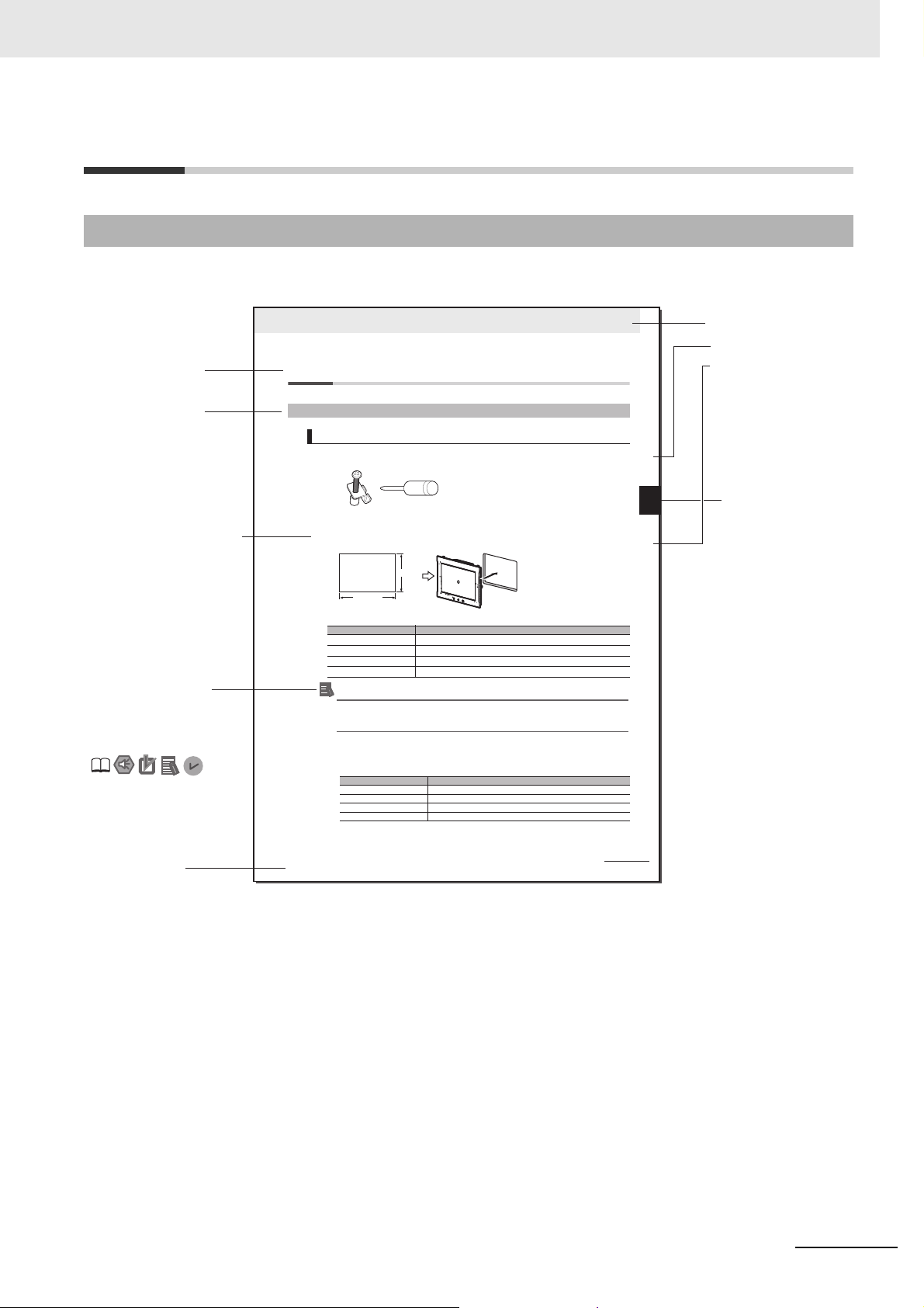
Manual Structure
Level 1 heading
Level 2 heading
Level 3 heading
Level 2 heading
A step in a procedure
Manual name
Special information
Level 3 heading
Page tab
Give the current
headings.
Indicates a procedure.
Icons indicate precautions,
additional information, or
reference information.
Gives the number
of the main section.
3 - 5
3 Installation and Wiring
NA Series Programmable Terminal Hardware User’s Manual (V117)
3-3 Installing NA-series PTs
3
3-3-1 Installation in a Control Panel
3-3 Installing NA-series PTs
The NA-series PT is installed by embedding it in a control panel. Panel Mounting Brackets and a Phillips screwdriver are
required to mount the NA-series PT. The required number of Panel Mounting Brackets are included with the NA-series PT.
Use the following installation procedure.
1 Open a hole in which to embed the NA-series PT with the following dimensions and insert the
NA-series PT from the front side of the panel.
Additional Information
You can use an NS-USBEXT-1M USB Relay Cable to extend the USB slave connector on the
back panel of the NA-series PT to the front surface of a control panel. If you use the USB Relay
Cable, open a hole with the following dimensions and install the Cable.
2 Attach the panel mounting brackets from the back of the panel as shown in the following figure.
The number of mounting brackets depends on the size of the NA-series PT, as shown in the following
table. Refer to Bracket Mounting Locations for Different NA-series PT Sizes on page 3-8, below.
Catch the brackets in the mounting holes in the NA-series PT, pull forward lightly, and then use
a Phillips screwdriver to tighten the screws and secure the NA-series PT to the panel, which will
be held between the mounting brackets and the NA-series PT.
3-3-1 Installation in a Control Panel
Installation in a Control Panel
Model Dimensions
NA5-15W
392
+1/-0
× 268
+1/-0
mm (horizontal × vertical)
NA5-12W
310
+1/-0
× 221
+1/-0
mm (horizontal × vertical)
NA5-9W
261
+1/-0
× 166
+1/-0
mm (horizontal × vertical)
NA5-7W
197
+ 0.5/-0
× 141
+0.5/-0
mm (horizontal × vertical)
Model Number of Panel Mounting Brackets
NA5-15W 8 locations
NA5-12W 6 locations
NA5-9W 4 locations
NA5-7W 4 locations
Panel Mounting Bracket Phillips screwdriver
Vertical
Horizontal
Recommended panel thickness: 1.6 to 6.0 mm
Page Structure and Markings
The following page structure is used in this manual.
Manual Structure
NA-series Programmable Terminal Software User’s Manual (V118)
Note This illustration is provided only as a sample. It may not literally appear in this manual.
3
Page 6

Manual Structure
Precautions for Safe Use
Precautions for Correct Use
Additional Information
Version Information
Special Information
Special information in this manual is classified as follows:
Precautions on what to do and what not to do to ensure safe usage of the product.
Indicates precautions on what to do and what not to do to ensure proper operation and performance.
Additional information to read as required.
This information is provided to increase understanding or make operation easier.
Information on differences in specifications and functionality with different versions is given.
4
NA-series Programmable Terminal Software User’s Manual (V118)
Page 7
10
11
A
1
2
3
4
5
6
7
8
9
1
2
3
I
4
5
6
7
8
9
Introduction to the NA-series
Programmable Terminals
Basic Sysmac Studio
Operations
Connecting to HMIs
from External Devices
HMI Configuration
and Setup
Creating the HMI
Application
Objects
Debugging
Connecting to the HMI
Synchronizing Projects
Reusing Objects
10
Other Functions
11
Appendices
A
Index
I
Sections in this Manual
Sections in this Manual
NA-series Programmable Terminal Software User’s Manual (V118)
5
Page 8

Sections in this Manual
6
NA-series Programmable Terminal Software User’s Manual (V118)
Page 9

CONTENTS
Introduction .............................................................................................................. 1
Relevant Manuals..................................................................................................... 2
Manual Structure...................................................................................................... 3
Sections in this Manual........................................................................................... 5
Terms and Conditions Agreement ....................................................................... 13
Safety Precautions................................................................................................. 15
Precautions for Safe Use ...................................................................................... 18
Precautions for Correct Use ................................................................................. 21
CONTENTS
Regulations and Standards .................................................................................. 22
Related Manuals..................................................................................................... 24
Terminology............................................................................................................ 31
Revision History..................................................................................................... 32
Section 1 Introduction to the NA-series Programmable Terminals
1-1 NA-series Programmable Terminals.................................................................................... 1-2
1-1-1 Features...................................................................................................................................... 1-2
1-2 How HMIs Operate................................................................................................................. 1-4
1-2-1 HMI Software Configuration........................................................................................................ 1-4
1-2-2 HMI Projects ............................................................................................................................... 1-4
1-2-3 Pages ......................................................................................................................................... 1-4
1-2-4 Objects........................................................................................................................................ 1-5
1-2-5 Memory Specifications for Connected Devices .......................................................................... 1-6
1-2-6 Events......................................................................................................................................... 1-7
1-2-7 Subroutines................................................................................................................................. 1-8
1-2-8 Functions Shared by the Entire HMI Project............................................................................... 1-9
1-2-9 Data That Retained When Power Is Turned OFF....................................................................... 1-9
1-3 Operating Procedure for HMIs ........................................................................................... 1-10
1-3-1 Overall Procedure..................................................................................................................... 1-10
1-3-2 Procedure Details ......................................................................................................................1-11
Section 2 Basic Sysmac Studio Operations
2-1 Parts of the Sysmac Studio Window ................................................................................... 2-2
2-1-1 Application Window .................................................................................................................... 2-2
2-2 Menu Command Structure.................................................................................................... 2-6
2-3 Basic Editing Operations...................................................................................................... 2-9
NA-series Programmable Terminal Software User’s Manual (V118)
7
Page 10

CONTENTS
2-4 Sysmac Studio Settings and Operations .......................................................................... 2-11
2-4-1 Setting Parameters ................................................................................................................... 2-11
2-4-2 Programming............................................................................................................................. 2-11
2-4-3 Library Functions....................................................................................................................... 2-12
2-4-4 Operations for Debugging ......................................................................................................... 2-12
2-4-5 Communications ....................................................................................................................... 2-12
2-4-6 Security Measures .................................................................................................................... 2-12
2-4-7 Online Help ............................................................................................................................... 2-13
2-4-8 Project Management Functions ................................................................................................2-13
2-5 Basic Operations for HMI Projects..................................................................................... 2-14
2-5-1 Creating a Project File from the Start Page...............................................................................2-14
2-5-2 Adding an HMI to an Existing Project........................................................................................ 2-15
2-5-3 Changing Devices .....................................................................................................................2-16
2-5-4 Importing and Exporting Devices .............................................................................................. 2-18
Section 3 HMI Configuration and Setup
3-1 Outline of Configurations and Setup ................................................................................... 3-2
3-1-1 Connected Device Registration and Variable Mapping............................................................... 3-2
3-2 Device References................................................................................................................. 3-3
3-2-1 Types of Connected Devices ......................................................................................................3-3
3-2-2 Connected Devices in the Current Project ..................................................................................3-3
3-2-3 Registering External Connected Devices....................................................................................3-4
3-3 Mapping Variables ................................................................................................................. 3-7
3-3-1 Mapping Variables....................................................................................................................... 3-7
3-3-2 Opening the Variable Mapping Tab Page and Tab Page Parts ................................................... 3-7
3-3-3 Variable Mapping Methods..........................................................................................................3-8
3-4 HMI Settings......................................................................................................................... 3-10
3-4-1 HMI Settings..............................................................................................................................3-10
3-4-2 Device Settings ......................................................................................................................... 3-11
3-4-3 TCP/IP Settings.........................................................................................................................3-13
3-4-4 FTP Settings .............................................................................................................................3-14
3-4-5 NTP Settings ............................................................................................................................. 3-15
3-4-6 FINS Settings ............................................................................................................................3-16
3-4-7 VNC Settings............................................................................................................................. 3-17
3-4-8 Printing Settings ........................................................................................................................3-18
3-5 Security Settings ................................................................................................................. 3-19
3-6 Troubleshooter .................................................................................................................... 3-20
3-7 Language Settings .............................................................................................................. 3-21
3-8 Operation Log Settings.......................................................................................................3-22
3-9 HMI Clock ............................................................................................................................. 3-25
3-10 Updating the HMI Name ...................................................................................................... 3-26
3-11 Write Protecting the HMI..................................................................................................... 3-27
3-12 Clear All Memory ................................................................................................................. 3-28
3-13 Resetting the HMI ................................................................................................................ 3-29
8
NA-series Programmable Terminal Software User’s Manual (V118)
Page 11

Section 4 Creating the HMI Application
4-1 Registering Variables............................................................................................................ 4-3
4-1-1 Variables ..................................................................................................................................... 4-3
4-1-2 Registering Global Variables ...................................................................................................... 4-4
4-1-3 Registering External Variables.................................................................................................... 4-6
4-1-4 Attributes and Entry Methods for Global Variables ................................................................... 4-10
4-1-5 System-defined Variables......................................................................................................... 4-14
4-1-6 Subroutine Variables................................................................................................................. 4-18
4-2 Registering Data Types .......................................................................................................4-19
4-3 Creating Pages .................................................................................................................... 4-20
4-3-1 Displaying Pages...................................................................................................................... 4-21
4-3-2 Registering Pages .................................................................................................................... 4-21
4-3-3 Page Property Settings............................................................................................................. 4-23
4-3-4 Editing Pages............................................................................................................................ 4-25
4-4 Setting Common Object Functions ................................................................................... 4-32
4-4-1 Registering User Alarms........................................................................................................... 4-32
4-4-2 Setting Controller Events.......................................................................................................... 4-33
4-4-3 Registration for Data Logging................................................................................................... 4-36
4-4-4 Registering Data Groups .......................................................................................................... 4-37
4-4-5 Registering Recipes.................................................................................................................. 4-39
4-4-6 Registering Custom Keypads ................................................................................................... 4-40
4-4-7 Setting Global Events and Corresponding Actions................................................................... 4-42
4-4-8 Registering Global Subroutines ................................................................................................ 4-44
4-4-9 Setting Up Resources............................................................................................................... 4-45
4-4-10 Setting Up IAG Resources........................................................................................................ 4-46
4-4-11 Registering Scaling ................................................................................................................... 4-47
4-5 Subroutines.......................................................................................................................... 4-50
4-5-1 Subroutine Execution................................................................................................................ 4-51
4-5-2 Precautions on Internal Processing.......................................................................................... 4-55
4-5-3 Code Editor............................................................................................................................... 4-56
4-5-4 Differences in Language Specifications.................................................................................... 4-56
4-6 Search and Replace ............................................................................................................ 4-57
4-7 Cross References ................................................................................................................ 4-58
4-7-1 Cross References..................................................................................................................... 4-58
4-8 Building ................................................................................................................................ 4-59
4-8-1 Building..................................................................................................................................... 4-59
4-8-2 Build Operation......................................................................................................................... 4-59
4-9 Offline Comparison ............................................................................................................. 4-60
CONTENTS
Section 5 Objects
5-1 Objects ................................................................................................................................... 5-2
5-1-1 Object List................................................................................................................................... 5-2
5-1-2 Object Attributes ......................................................................................................................... 5-4
5-1-3 Using Objects ............................................................................................................................. 5-8
5-2 Examples of Using Objects ................................................................................................ 5-12
5-2-1 Displaying a PDF File ............................................................................................................... 5-12
5-2-2 Displaying a User Alarm ........................................................................................................... 5-14
5-2-3 Displaying a Trend Graph......................................................................................................... 5-16
5-2-4 Displaying a Broken-line Graph................................................................................................ 5-18
5-2-5 Using a Recipe ......................................................................................................................... 5-21
5-2-6 Setting the Order of Automatic Move of Input Focus................................................................ 5-25
5-2-7 Displaying Text Strings by Indirect Addressing......................................................................... 5-27
5-2-8 Creating Buttons with the Lamp Function................................................................................. 5-29
5-2-9 Creating Buttons to Output Operation Log Files....................................................................... 5-31
NA-series Programmable Terminal Software User’s Manual (V118)
9
Page 12

CONTENTS
Section 6 Connecting to the HMI
6-1 Introduction............................................................................................................................ 6-2
6-2 Going Online with an HMI .....................................................................................................6-3
6-2-1 Methods for Going Online with an HMI .......................................................................................6-3
6-2-2 Setting the Connection Method...................................................................................................6-4
6-2-3 Online Connection....................................................................................................................... 6-5
6-2-4 Going Online after Checking the Connection Method.................................................................6-6
6-2-5 Going Offline ............................................................................................................................... 6-6
6-2-6 Confirming Serial IDs ..................................................................................................................6-7
Section 7 Debugging
7-1 HMI Debugging Functions .................................................................................................... 7-2
7-1-1 Watch Tab Page..........................................................................................................................7-3
7-1-2 Breakpoints ................................................................................................................................. 7-3
7-1-3 Step Execution ............................................................................................................................7-5
7-1-4 Simulator Functions .................................................................................................................... 7-8
7-1-5 Offline Debugging with Only the HMI Simulator .......................................................................... 7-9
7-1-6 Offline Debugging with the Controller Simulator .......................................................................7-10
Section 8 Synchronizing Projects
8-1 Synchronizing Projects......................................................................................................... 8-2
8-2 Downloading .......................................................................................................................... 8-6
8-2-1 Downloading While Online ..........................................................................................................8-6
8-2-2 Using Storage Media for Downloading........................................................................................8-7
8-3 Uploading ............................................................................................................................. 8-10
8-3-1 Uploading Projects Online.........................................................................................................8-10
8-3-2 Uploading with the Upload Function .........................................................................................8-12
8-3-3 Uploading with Storage Media ..................................................................................................8-13
8-3-4 Relinking Internal Devices.........................................................................................................8-17
Section 9 Reusing Objects
9-1 Reusing Objects .................................................................................................................... 9-2
9-2 IAGs ........................................................................................................................................ 9-3
9-2-1 Differences when an IAG Project Is Selected .............................................................................9-3
9-2-2 Creating an IAG ........................................................................................................................ 9-10
9-2-3 Using IAGs ................................................................................................................................ 9-13
9-3 Custom Objects ................................................................................................................... 9-16
9-3-1 Objects That You Can Register as Custom Objects .................................................................9-16
9-3-2 Creating Custom Objects ..........................................................................................................9-16
9-3-3 Deleting Custom Objects .......................................................................................................... 9-19
9-3-4 Using Custom Objects ..............................................................................................................9-20
Section 10 Connecting to HMIs from External Devices
10-1 Accessing an HMI from an External Device...................................................................... 10-2
10-1-1 VNC...........................................................................................................................................10-2
10-1-2 FTP ...........................................................................................................................................10-3
10
NA-series Programmable Terminal Software User’s Manual (V118)
Page 13

Section 11 Other Functions
11-1 Sysmac Studio Option Settings ......................................................................................... 11-2
11-2 Printing ................................................................................................................................. 11-5
11-2-1 Printable Items...........................................................................................................................11-5
11-3 Image File Output ................................................................................................................ 11-6
11-4 Import/Export User Alarm................................................................................................... 11-7
11-4-1 Importing User Alarms ...............................................................................................................11-7
11-4-2 Exporting User Alarms...............................................................................................................11-9
11-4-3 File Format...............................................................................................................................11-11
11-5 Import/Export Resources.................................................................................................. 11-13
11-5-1 Importing Resources................................................................................................................11-13
11-5-2 Exporting Resources ...............................................................................................................11-16
11-5-3 File Format...............................................................................................................................11-19
11-6 Import/Export Object Properties ...................................................................................... 11-20
11-6-1 Importing Object Properties .....................................................................................................11-20
11-6-2 Exporting Object Properties.....................................................................................................11-21
11-6-3 File Format...............................................................................................................................11-22
11-7 Importing/Exporting Pages............................................................................................... 11-24
11-7-1 Importing Pages.......................................................................................................................11-24
11-7-2 Exporting Pages ......................................................................................................................11-25
CONTENTS
Appendices
A-1 Events and Actions ...............................................................................................................A-2
A-2 Supported Formats ...............................................................................................................A-5
A-3 Specifications of Operation Log Files .................................................................................A-7
A-4 Differences between the Physical HMI and Simulator .....................................................A-10
A-5 Version Upgrade History.....................................................................................................A-11
A-5-1 Version Upgrade History for Sysmac Studio and Runtime ....................................................... A-11
A-5-2 Version Upgrade History for Sysmac Studio Only ....................................................................A-13
A-5-3 Sysmac Studio Corresponding Versions ..................................................................................A-17
A-6 Precautions for Version Upgrades.....................................................................................A-18
Index
NA-series Programmable Terminal Software User’s Manual (V118)
11
Page 14

CONTENTS
12
NA-series Programmable Terminal Software User’s Manual (V118)
Page 15

Terms and Conditions Agreement
Terms and Conditions Agreement
Warranty, Limitations of Liability
Warranties
z Exclusive Warranty
Omron’s exclusive warranty is that the Products will be free from defects in materials and workmanship for a period of twelve months from the date of sale by
writing by Omron). Omron disclaims all other warranties, express or implied.
z Limitations
OMRON MAKES NO WARRANTY OR REPRESENTATION, EXPRESS OR IMPLIED, ABOUT
NON-INFRINGEMENT, MERCHANTABILITY OR FITNESS FOR A PARTICULAR PURPOSE OF
THE PRODUCTS. BUYER ACKNOWLEDGES THAT IT ALONE HAS DETERMINED THAT THE
PRODUCTS WILL SUITABLY MEET THE REQUIREMENTS OF THEIR INTENDED USE.
Omron further disclaims all warranties
on infringement by the Products or otherwise of any intellectual property right.
and resp
onsibility of any type for claims or expenses based
Omron (or such other period expressed in
z Buyer Remedy
Omron’s sole obligation hereunder shall be, at Omron’s election, to (i) replace (in the form originally
shipped with Buyer responsible for labor charges for removal or replacement thereof) the non-complying Product, (ii) repair the non-complying Product, or (iii) rep
to the purchase price of the non-complying Product; provided that in no event shall Omron be
responsible for warranty, repair, indemnity or any other claims or expenses regarding the Products
unless Omron’s analysis confirms that the Products were properly handled, stored, installed and
maintained and not subject to contamination, abuse, misuse or inappropriate modification. Return of
any Products by Buyer must be approved in writing by Omron before shipment. Omron Companies
shall not be liable for the suitability or unsuitability or the results from the use of Products in combination with any electrical or electronic components, circuit
als or substances or environments. Any advice, recom
writing, are not to be construed as an amendment or addition to the above warranty.
See http://www.omron.com/global/ or contact your Omron representative for published information.
mendations or information given orally or in
ay or credit Buyer an amount equal
ystem assemblies or any other materi-
s, s
Limitation on Liability; Etc
OMRON COMPANIES SHALL NOT BE LIABLE FOR SPECIAL, INDIRECT, INCIDENTAL, OR CONSEQUENTIAL DAMAGES, LOSS OF PROFITS OR PRODUCTION OR
WAY CONNECTED WITH THE PRODUCTS, WHETHER SUCH CLAIM IS BASED IN CONTRACT,
WARRANTY, NEGLIGENCE OR STRICT LIABILITY.
Further, in no event shall liability of Omron
which liability is asserted.
Companies exc
eed the individual price of the Product on
COMMERCIAL LOSS IN ANY
NA-series Programmable Terminal Software User’s Manual (V118)
13
Page 16

Terms and Conditions Agreement
Application Considerations
Suitability of Use
Omron Companies shall not be responsible for conformity with any standards, codes or regulations
which apply to the combination of the Product in the Buyer’s application or use of the Product. At
Buyer’s request, Omron will provide applicable third party certification documents identifying ratings
and limitations of use which apply to the Product. This information by itself is not sufficient for a complete determination of the suitability of the Product in combination with the end product, machine, system, or other application or use. Buyer shall be sole
the particular Product with respect to Buyer’s application, product or system. Buyer shall take application responsibility in all cases.
NEVER USE THE PRODUCT FOR AN APPLICATION INVOL
PROPERTY OR IN LARGE QUANTITIES WITHOUT ENSURING THAT THE SYSTEM AS A WHOLE
HAS BEEN DESIGNED TO ADDRESS THE RISKS, AND THAT THE OMRON PRODUCT(S) IS
PROPERLY RATED AND INSTALLED FOR THE INTENDED USE WITHIN THE OVERALL EQUIPMENT OR SYSTEM.
ly re
sponsible for determining appropriateness of
VING SERIOUS RISK T
O LIFE OR
Programmable Products
Omron Companies shall not be responsible for the user’s programming of a programmable Product, or
any consequence thereof.
Disclaimers
Performance Data
Data presented in Omron Company websites, catalogs and other materials is provided as a guide for
the user in determining suitability and does not constitute a warranty. It may represent the result of
Omron’s test conditions, and the user must correlate it to actual application requirements. Actual performance is subject to the Omron’s Warranty
Change in Specifications
Product specifications and accessories may be changed at any time based on improvements and other
reasons. It is our practice to change part numbers when published ratings or features are changed, or
when significant construction changes are made. However, some specifications of the Product may be
changed without any notice. When in doubt, special part numbers may be assigned to fix or establish
key specifications for your application. Please consult with your Omron’s representative at any time to
confirm actual specifications of purchased Product.
and Limita
tions of Liability.
14
Errors and Omissions
Information presented by Omron Companies has been checked and is believed to be accurate; however, no responsibility is assumed for clerical, typograp
NA-series Programmable Terminal Software User’s Manual (V118)
hical or proofreading errors or omissions.
Page 17
Safety Precautions
Indicates a potentially hazardous situation which, if
not avoided, could result in mild or moderate injury or
at the worst, serious injury or death. Additionally,
there may be severe property damage.
Indicates a potentially hazardous situation which, if not
avoided, may result in minor or moderate injury, or
property damage.
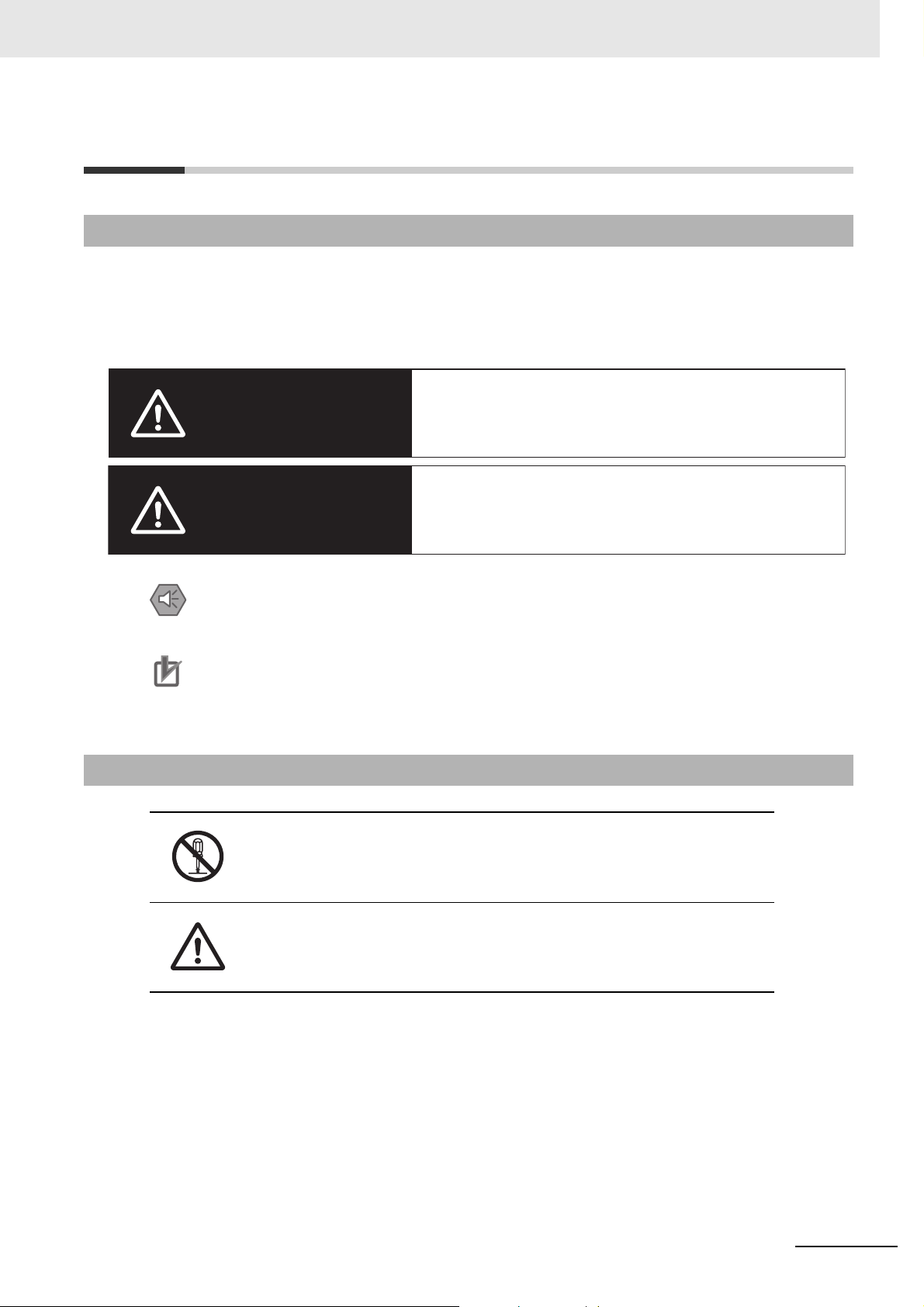
Definition of Precautionary Information
The following notation is used in this manual to provide precautions required to ensure safe usage of
the NA-series Programmable Terminal. The safety precautions that are provided are extremely important to safety. Always read and heed the information provided in all safety precautions.
The following notation is used.
WARNING
Safety Precautions
Indicates precautions on what to do and what not to do to ensure safe usage of the product.
Indicates precautions on what to do and what not to do to en
Symbols
Caution
Precautions for Safe Use
Precautions for Correct Use
sure proper operation and performance.
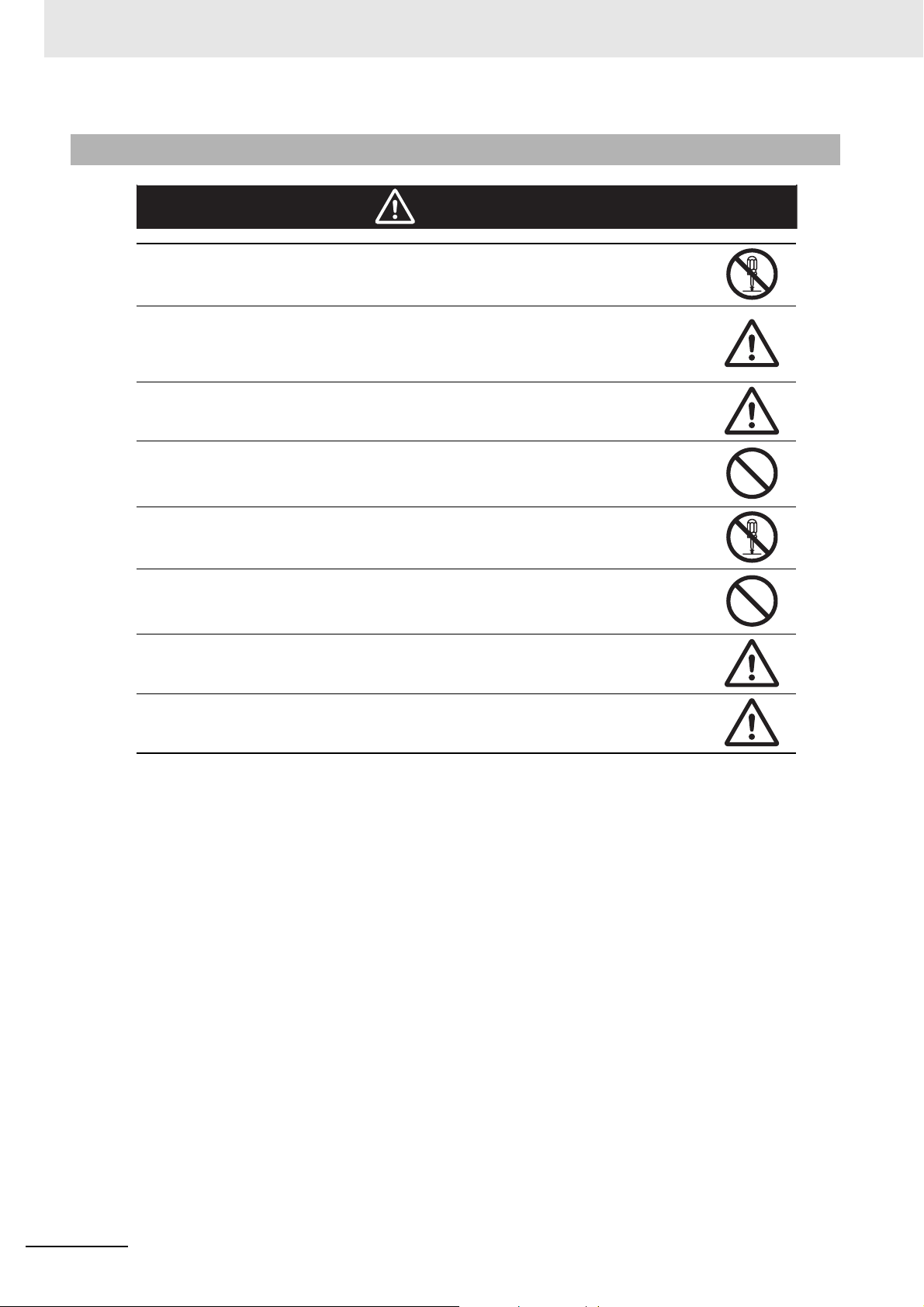
The circle and slash symbol indicates operations that you must not do.
The specific operation is shown in the circle and explained in text.
This example indicates prohibiting disassembly.
The triangle symbol indicates precautions (including warnings).
The specific operation is shown in the triangle and explained in text.
This example indicates a general precaution.
NA-series Programmable Terminal Software User’s Manual (V118)
15
Page 18
Safety Precautions
WARNING
Warnings
Do not attempt to take the NA Unit apart and do not touch the product inside while the
power is being supplied. Otherwise it may result in electric shock.
Always ensure that the personnel in charge confirm that installation, inspection, and
maintenance were properly performed for the NA Unit. “Personnel in charge” refers to
individuals qualified and responsible for ensuring safety during machine design,
installation, operation, maintenance, and disposal.
Ensure that installation and post-installation checks are performed by personnel in charge
who possess a thorough understanding of the machinery to be installed.
Do not use the input functions such as the touch panel or function keys of the NA Unit, in
applications that involve human life, in applications that may result in serious injury, or for
emergency stop switches.
Do not attempt to disassemble, repair, or modify the NA Unit. It may cause NA Unit to lose
its safety function.
Never press two points or more on the touch panel of the NA Unit at a time. Touching two
points or more interrupts normal touch panel operations.
To conform to UL Type 4X standards, always use the NA5-W (-V1) with a
High-pressure Waterproof Attachment (PWA). If you do not use a PWA, there is a risk of
water entry, which may cause severe equipment damage.
Always pay attention to the inside dimensions when you mount a PWA on the
NA5-W (-V1). If you do not mount the PWA correctly, there is a risk of water
entry, which may cause severe equipment damage.
16
NA-series Programmable Terminal Software User’s Manual (V118)
Page 19
Additional Information
Precaution
WARNING
Internal
non-isolated
power
supply
NA5-W-V1
SG
External
non-isolated
device
SG
24 V
0 V
+
GND
Power
Supply
Grounding
Grounding
Protective ground
Functional ground
Shielded
cable
Hood
PC
USB memory device
Hood
Fuse
Fuse
Non-isolated
power
supply
24 VDC
GND
PE (Protective ground)
Ethernet
connector
hood
Serial
connector
hood
USB slave
connector
hood
USB host
connector
hood
FG (Functional ground)
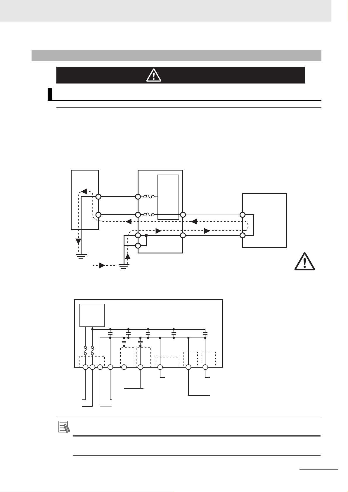
Wiring
Observe the following precautions when wiring the NA5-W-V1.
The internal power supply in the NA5-W-V1 is a non-isolated DC power supply. Never
ground the 24 V side. If the 24 V power supply to the NA is grounded positively, a short circuit will
occur as shown below and may result in damage to the device.
24 V Grounding Power Supply
Safety Precautions
NA5-W-V1 grounding diagram
The internal power supply of the NA5-W Product uses an isolated DC power sup-
NA-series Programmable Terminal Software User’s Manual (V118)
ply, and therefore is not susceptible to the effects of grounding of the 24 V side.
17
Page 20
Precautions for Safe Use
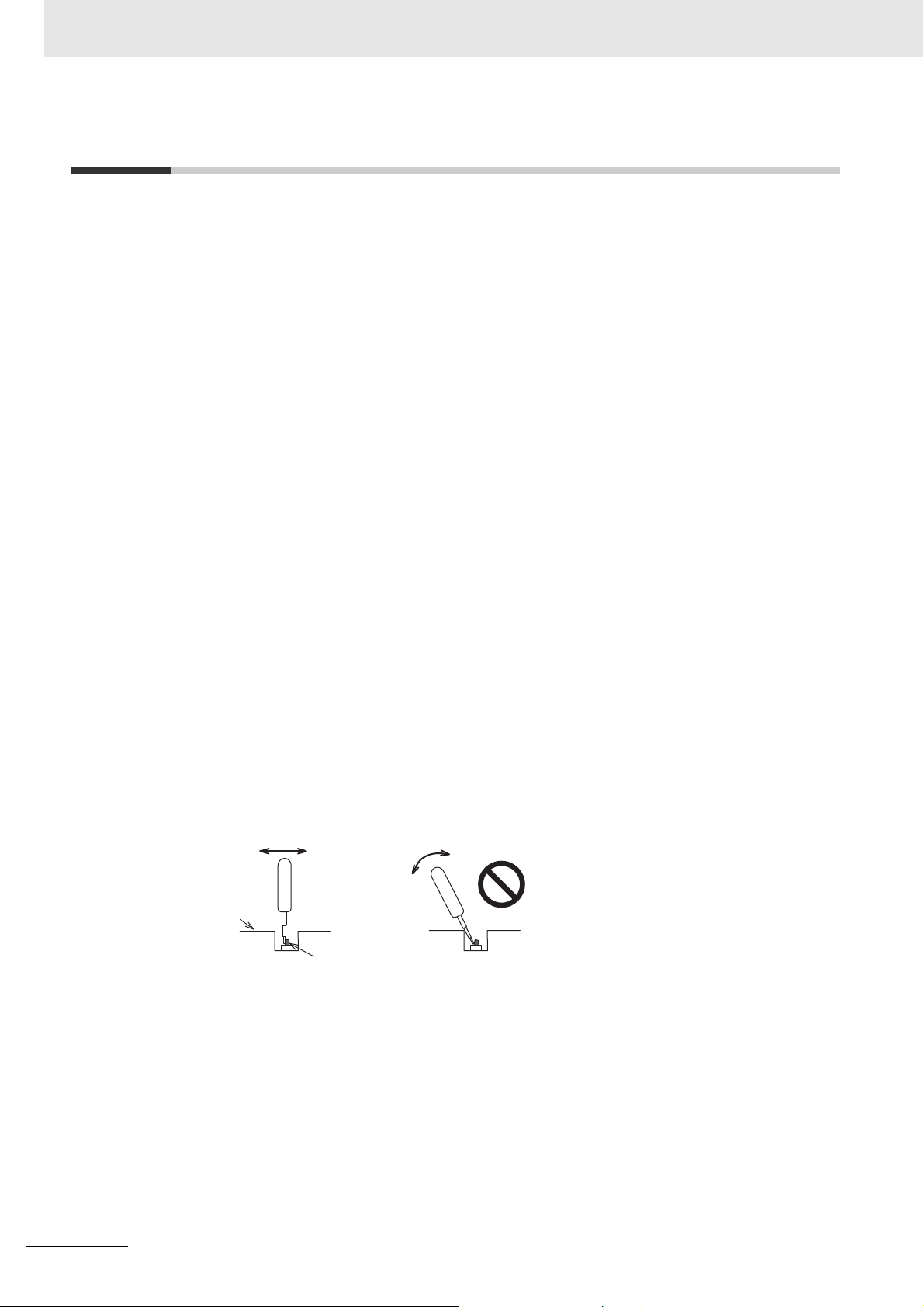
Back of the case
DIP switch
Correct technique
Incorrect technique
Precautions for Safe Use
• When unpacking the NA Unit, check carefully for any external scratches or other damages. Also,
shake the NA Unit gently and check for any abnormal sound.
• The NA Unit must be installed in a control panel.
To conform to UL Type 1 standards, the mounting panel thickness must be 1.6 to 6.0 mm.
•
To conform to UL Type 4X standards, the thickness must be 1.6 to 4.5 mm.
To conform to UL Type 4X standards, always use the NA5-W (
Waterproof Attachment (PWA). If you do not use a PWA, there is a risk of water entry, which may
cause severe equipment damage. Do not use the NA Unit outdoors. Tighten the Mounting Brackets
evenly to a torque of between 0.5 and 0.6 N·m to maintain water and dust resistance. If the tightening
torque exceeds the specified value, or the tightening is not even, deformation of the front panel may
occur. What is more, make sure the panel is not dirty or warped, that the front surface is smooth, and
that the panel is strong enough to hold the NA Unit.
• Do not let metal particles enter the NA Unit when preparing the panel.
• Turn OFF the power supply before con
• Periodically check the installation conditions in applications wh
with oil or water.
• Be certain to use the cables with lock mechanism such as serial
confirming if it is securely locked.
• Do not touch the packaging part of the circuit board with your bare hands. Discharge any static electricity from your body before handling the board.
• Do not use volatile solvents such as benzene and thinn
• Water and oil resistance will be lost if the front sheet is
if the front sheet is torn or is peeling off.
• As the rubber packing will deteriorate, shrink
periodical inspection is necessary.
• Confirm the safety of the system before
switch.
• The whole system may stop depending on how th
the power supply according to the specified procedure.
• Operate DIP switch according to the following way
necting or
turning ON or OFF the power supply, or pressing the reset
disconnecting cables.
, or harden depending on the operating environment,
e power supply is turned ON or OFF. Turn ON/OFF
.
-V1) with a High-pressure
ere the NA Unit is subject to contact
cable or the Ethernet cable after
ers or chemical cloths.
torn or is peeling off. Do not use the NA Unit,
18
The DIP switch may break if it is levere
• Once the DIP switch settings are changed, reset by pressing
supply.
• Initialize the project, after confirming that existin
• When changing the password, do not reset or turn OFF the power supply until the writing is completed. A failure to store the password may caus
• While uploading or downloading a project or a system program, do not perform the operations as follows. Such operations may corrupt the projec
• Turning OFF the power supply of the NA Unit
• Resetting the NA Unit.
• Removing the USB devices or SD card.
d with a tool against the case as shown in the figure.
the reset switch, or restart the power
g project is backed up at the Sysmac Studio.
e the project to fail to function.
t or the system program:
NA-series Programmable Terminal Software User’s Manual (V118)
Page 21

Precautions for Safe Use
• Disconnecting the cable between a support tool and the NA Unit.
• Do not connect an AC power supply to the DC power terminals.
• Do not perform a dielectric strength test.
• Use a DC power with a slight voltage fluctuation and that will provide a stable output even if the input
is
momentarily interrupted for 10 ms. Also use the one with reinforced insulation or double insulation.
Rated Power Supply Voltage: 24 VDC (Allowable range 19.2 to 28.8 VDC)
2
• Use a power cable with AWG#12 to #22 thick (0.35 mm
and tighten the terminal screw with the torque in the range of 0.5 to 0.6 N·m. Also confirm if the terminal screw is tighten appropriately.
• Ground the NA Unit correctly.
• When using the NA5-W-V
1, to help prevent electrical shock, ground to 100 Ω or less by
using dedicated ground wires (with cross-section area of 2 mm
screw on the protective ground terminal to a torque of 1.0 to 1.2 N·m.
• Do not use any battery if strong impact is applied to it (e.g. b
battery may cause a leakage.
• Confirm the type of the battery to install the battery properly.
• Apply power for at least five minutes before changing th
minutes after turning OFF the power supply. If power is not supplied for at least five minutes, the
clock data may be lost. Check the clock data after changing the battery.
• Do not dismantle a battery nor let it short-circuit.
• Do not apply an impact with the lithium battery, charge it, dispose it
of them may cause an ignition or a bursting.
• Dispose of the NA Units and batteries according to local ordinances as they apply.
to 3.31 mm2). Peel the coating 7 mm length
2
or larger) and tighten the terminal
y dropping on the floor) because such a
e battery. Mount a new battery within five
into a fire, or heat it. Doing either
• The following precaution must be displayed on all products containing lithium primary batteries with a
perchlorate content of 6 ppb or higher when exporting them to or shipping them through California,
USA.
Perchlorate Material - special handling may apply.
See www.
dtsc.ca.gov/hazardouswaste/perchlorate
The NA-Series contains a lithium primary battery with a perchlorate content of 6 ppb or higher. When
exporting a product containing the NA-Series to or shipping such a product through California, USA,
label all packing and shipping containers appropriately.
• Do not connect the USB devices in the environment subject to the strong vibration.
• Use a USB memory device for temporary purposes such as data transfer.
• Do not connect USB devices which are not allowed to connect to NA Unit.
• Start actual system application only after checking normal operation of th
e system including storage
devices such as USB memory and SD card.
• When connecting peripheral devices which do not meet
the performance level of the NA Unit for
noise and static electricity, ensure sufficient countermeasures against noise and static electricity during installation of the peripheral devices to th
• Do not carry out the following operations when a
e NA Unit.
ccessing USB devices or SD card:
• Turning OFF the power supply of the NA Unit
• Press the Reset switch of the NA Unit
• Pull out the USB devices or SD card
• When using the No. 6 pin of the serial port connector for
a voltage of DC+5 V, make sure the supply
equipment's current capacity is below 250 mA before using it. The DC+5 V voltage output of the NA
Unit is +5 V±5%, and the maximum current is 250 mA.
NA-series Programmable Terminal Software User’s Manual (V118)
19
Page 22

Precautions for Safe Use
• To ensure the system's safety, make sure to incorporate a program that call periodically signals during the operation at connected device side
before running the system.
• Start actual system application only after sufficiently checking p
the program at the connected device side.
• To execute a subroutine with multiple threads, fully check the opera
multithreads into consideration, before starting actual system application.
• To use numeric input functions safely, always make maximum and minimum limit settings.
• Do not press the touch panel with a force greater than 30 N.
• Do not use hard or pointed objects to operate or scrub the screen, otherwise the surface of the
screen may be
• The deterioration over time may cause the touch points to move on the touch panel. Calibrate the
touch p
• A touch position detection error of approximately 20 pixels m
touch panel. Always take this into account when positioning objects on the panel so adjoining objects
will not be activated by mistake.
• Confirm the safety of the system before
• Do not accidentally press the touch panel when the backlight
appear or is too dark to identify visually.
• You can change the brightness by changing the setting such as in the system menu or by downloading project.
If the brightness is set to very dark, it causes flickering or unreadable screen. Additionally, the brightness can be restored by transferring the project again after setting the property of the brightness
a
In a case of the applications where end users can control the
as keeping on operations by such as assigning the function which restores the brightness to one of
function keys, if necessary.
• Signals from the touch panel may not be entered if the to
speed. Make sure to go on the next operation after confirming that the NA Unit has detected the input
of the touch panel.
• The function keys have the restrictions as follows:
anel periodically.
pprop
riately.
• When you use gloves or others, the function keys may not work correctly depending on the material and thickness of the gloves. Take actual conditions of the
prior to the system startup to perform the confirmation.
• The function keys do not work when covered with water.
use.
damaged.
and can confirm the normal functionality of the NA Unit
roject, subroutine and the operation of
tion of the program that takes
ay occur due to the precision of the
pressing the touch panel.
is not lit or when the display does not
brightness, create the applications so
uch panel is pressed consecutively at high
gloves usage into considerations
Remove the water completely before
20
NA-series Programmable Terminal Software User’s Manual (V118)
Page 23

Precautions for Correct Use
z Do not install or store the NA Unit in any of the following locations:
• Locations subject to severe changes in temperature
• Locations subject to temperatures or humidity outside
• Locations subject to condensation as the resu
• Locations subject to corrosive or flam
• Locations subject to strong shock or vibration
• Locations outdoors subject to direct wind and rain
• Locations subject to strong ultraviolet light
• Locations subject to dust
• Locations subject to direct sunlight
• Locations subject to splashing oil or chemicals
mable gases
lt of high humidity
the range specified in the specifications
Precautions for Correct Use
z Take appropriate and sufficient countermeasures when installing systems in
the following locations:
• Locations subject to static electricity or other forms of noise
• Locations subject to strong electric field or
• Locations close to power supply lines
• Locations subject to possible expo
sure to radioactivity
magnetic field
z Mounting Panel
• To conform to UL Type 1 standards, the mounting panel thickness must be 1.6 to 6.0 mm.
• To conform to UL Type 4X standards, the thickness must be 1.6 to 4.5 mm.
To conform to UL Type 4X standards, always use the NA5-W (-V1)
sure Waterproof Attachment (PWA). If you do not use
may cause severe equipment damage.
• Tighten the Mounting Brackets evenly to a torque of betwee
and dust resistance. If the tightening torque exceeds the specified range or the tightening is not
even, deformation of the front panel may occur. Make sure the panel is not dirty or warped, that
the front surface is smooth, and that the panel is strong enough to hold the NA Unit.
a PWA, there is a risk of water entry, which
n 0.5 and 0.6 N·m to maintain water
with a High-pres-
NA-series Programmable Terminal Software User’s Manual (V118)
21
Page 24

Regulations and Standards
Regulations and Standards
Conformance to EC Directives
Applicable Directives
• EMC Directive
Concepts
z EMC Directive
OMRON devices that comply with EC Directives also conform to the related EMC standards so that
they can be more easily built into other devices or the overall machine. The actual products have
been checked for conformity to EMC standards.*
Whether the products conform to the standards in the
be checked by the customer. EMC-related performance of the OMRON devices that comply with EC
Directives will vary depending on the configuration, wiring, and other conditions of the equipment or
control panel on which the OMRON devices are installed. The customer must, therefore, perform
the final check to confirm that devices and the overall machine conform to EMC standards.
* Applicable EMC (Electromagnetic Compatibility) standards are as follows:
EMS (Electromagnetic Susceptibility): EN
EMI (Electro
magnetic Interference): EN 61131-2:2007
61131-2:2007
system used by
the customer, however, must
z Conformance to EC Directives
The NA-series PTs comply with EC Directives. To ensure that the machine or device in which the
NA-series PT is used complies with EC Directives, the NA-series PT must be installed as follows:
• The NA Unit must be installed within a control panel.
• You must use reinforced insulation or double insulation for the DC power supplies connected to
the NA Unit.
• NA-series P
(EN 61000-6-4). Radiated emission characteristics (10-m regulations) may vary depending on the
configuration of the control panel used, other devices connected to the control panel, wiring, and
other conditions.
You must therefore confirm that the overall mach
• This is a Class A product (for industrial environment
radio interference, in which case the user may be required to take appropriate measures.
Ts that comply with EC Directives also confo
ine
rm to the Common Emission Standard
or equipment complies with EC Directives.
s). In a residential environment, it may cause
22
NA-series Programmable Terminal Software User’s Manual (V118)
Page 25

Conformance to KC Standards
When you use this product in South Korea, observe the following precautions.
This product meets the electromagnetic compatibility requirements for business use. There is a risk of
radio interference when this product is used in home.
Regulations and Standards
NA-series Programmable Terminal Software User’s Manual (V118)
23
Page 26

Related Manuals
Related Manuals
The following manuals are related to the NA-series PTs. Use these manuals for reference.
Manual name Cat. No. Models Applications Description
NA-series Programmable Terminal Hardware User’s Manual
NA-series Programmable Terminal Hardware(-V1) User’s
Manual
NA-series Programmable Terminal Software User’s Manual
NA-series Programmable Terminal
Device Connection
User’s Manual
NA-series Programmable Terminal
Soft-NA User’s Manual
NA-series Programmable Terminal
Startup Guide
V117 NA5-W
V125 NA5-W-V1
V118 NA5-W (-V1)
V119 NA5-W (-V1) Learning the speci-
V126 NA-RTLD Learning about the
V120 NA5-W Learning in con-
Learning the specifications and settings required to
install an NA-series
PT and connect
peripheral devices.
Learning the specifications and settings required to
install an NA-series
PT and connect
peripheral devices.
Learning about
NA-series PT pages
and object functions.
fications required
to connect devices
to an NA-series PT.
procedure to install
the Soft-NA and
differences from
the NA5 series.
crete terms information required to
install and start the
operation of an
NA-series PT.
Information is provided on NA-series
PT specifications, part names, installation procedures, and procedures to
connect an NA Unit to peripheral
devices.
Information is also provided on maintenance after operation and troubleshooting.
Information is provided on NA-series
PT specifications, part names, installation procedures, and procedures to
connect an NA Unit to peripheral
devices.
Information is also provided on maintenance after operation and troubleshooting.
NA-series PT pages and object functions are described.
Information is provided on connection procedures and setting procedures to connect an NA-series PT to
a Controller or other device.
Information is provided on the specifications of the Soft-NA and differences
from the NA5 series.
Information is also provided on maintenance after operation and troubleshooting.
The part names and installation procedures are described followed by
page creation and transfer procedures with the Sysmac Studio. Also
operation, maintenance, and inspection procedures after the project is
transferred are described. Sample
screen captures are provided as
examples.
24
NA-series Programmable Terminal Software User’s Manual (V118)
Page 27

Related Manuals
Manual name Cat. No. Models Applications Description
NX-series CPU Unit
Hardware User's
Manual
NJ-series CPU Unit
Hardware User’s
Manual
NJ/NX-series CPU
Unit Software User´s
Manual
NJ/NX-series Instructions Reference Manual
NJ/NX-series Troubleshooting Manual
W535 NX701- Learning the basic
specifications of
the NX-series CPU
Units, including
introductory information, designing,
installation, and
maintenance.
Mainly hardware
information is provided.
W500 NJ501-
NJ301-
NJ101-
W501 NX701-
NX1P2-
NX102-
NJ501-
NJ301-
NJ101-
W502 NX701-
NX102-
NX1P2-
NJ501-
NJ301-
NJ101-
W503 NX701-
NX102-
NX1P2-
NJ501-
NJ301-
NJ101-
Learning the basic
specifications of
the NJ-series CPU
Units, including
introductory information, designing,
installation, and
maintenance.
Mainly hardware
information is provided.
Learning how to
program and set
up an
NJ/NX-series CPU
Unit.
Mainly software
information is provided.
Learning detailed
specifications on
the basic instructions of an
NJ/NX-series CPU
Unit.
Learning about the
errors that may be
detected in an
NJ/NX-series Controller.
An introduction to the entire NX-series
system is provided along with the following information on the CPU Unit.
• Features and system configuration
• Introduction
• Part names and functions
• General specifications
• Installation and wiring
• Maintenance and inspection
Use this manual together with the
NJ/NX-series CPU Unit Software
User's Manual (Cat. No.W501).
An introduction to the entire
NJ-series system is provided along
with the following information on a
Controller built with a CPU Unit.
• Features and system configuration
• Introduction
• Part names and functions
• General specifications
• Installation and wiring
• Inspection and maintenance
Use this manual together with the
NJ-series CPU Unit Software User’s
Manual (Cat. No. W501).
Provides the following information on
a Controller built with an
NJ/NX-series CPU Unit.
• CPU Unit operation
• CPU Unit features
• Initial settings
• Programming based on IEC
61131-3 language specifications
The instructions in the instruction set
(IEC 61131-3 specifications) are
described.
Concepts on managing errors that
may be detected in an NJ/NX-series
Controller and information on individual errors are described.
NA-series Programmable Terminal Software User’s Manual (V118)
25
Page 28

Related Manuals
Manual name Cat. No. Models Applications Description
CJ Series Programmable Controllers
Operation Manual
CS/CJ/NSJ Series
Programmable Controllers Operation
Manual
CS/CJ/NSJ-series
Instructions Reference Manual
CS/CJ Series Programming Consoles
Operation Manual
W393 CJ1H-CPUH-R
CJ1G/H-CPUH
CJ1G-CPUP
CJ1M-CPU
CJ1G-CPU
W394 CS1G/H-CPUH
CS1G/H-CPU-V1
CS1D-CPUH
CS1D-CPUS
CJ1H-CPUH-R
CJ1G/H-CPUH
CJ1G-CPUP
CJ1M-CPU
CJ1G-CPU
NSJ-(B)-G5D
NSJ-(B)-M3D
W340 CS1□-CPU--
CJ1□-CPU--
CJ2H-CPU--
NSJ--
W341 CQM1H-PRO01
CQM1-PRO01
C200H-PRO27
+CS1W-KS001
Learning the basic
specifications of
the CJ-series
PLCs, including
introductory information, designing,
installation, and
maintenance.
Learning about the
functions of the
CS/CJ-series and
NSJ-series PLCs.
Learning detailed
information on programming ins
tions.
Learning the operating procedures of
the Programming
Consoles.
truc-
The following information is provided
on a CJ-series PLC.
• Introduction and features
• System configuration design
• Installation and wiring
• I/O memory allocation
• Troubleshooting
Use this manual together with the
Programming Manual (Cat. No.
W394).
The following information is provided
on a CS/CJ-series or NSJ-series
PLC.
• Programming
• Master function
• File memory
• Other functions
Use this manual together with the
Operation Manual (CS-series PLCs:
W339, CJ-series PLCs: W393).
ctions are described in detail.
Instru
When programming, use this manual together with the Operation Man-
ual (CS-series PLCs: W339,
CJ-series PLCs: W393) and the Pro-
gramming Manual (W394).
The operating procedures of the Programming Consoles are described.
When programming, use this manual together with the Operation Man-
ual (CS-series PLCs: W339,
CJ-series PLCs: W393), the Pro-
gramming Manual (W394), and the
Instructions Reference Manual
(W340).
26
NA-series Programmable Terminal Software User’s Manual (V118)
Page 29

Related Manuals
Manual name Cat. No. Models Applications Description
CS/CJ/NSJ Series
Communications
Commands Reference Manual
CJ-series CJ2 CPU
Unit Hardware User’s
Manual
CJ-series CJ2 CPU
Unit Software User’s
Manual
Ethernet Units Operation Manual Construction of Networks
Ethernet Units Operation Manual Construction of
Applications
W342 CS1G/H-CPUH
CS1G/H-CPU-V1
CS1D-CPUH
CS1D-CPUS
CS1W-SCU-V1
CS1W-SCB-V1
CJ1G/H-CPUH
CJ1G-CPUP
CJ1M-CPU
CJ1G-CPU
CJ1W-SCU-V1
W472 CJ2H-CPU6-EIP
CJ2H-CPU6
CJ2M-CPU
W473 CJ2H-CPU6-EIP
CJ2H-CPU6
CJ2M-CPU
W420 CS1W-ETN21
CJ1W-ETN21
W421 CS1W-ETN21
CJ1W-ETN21
Learning detailed
specifications on
the communications instructions
addressed to
CS/CJ-series CPU
Units and
NSJ-series PLCs.
Learning the hardware specifications of CJ2 CPU
Units.
Learning the software specifications of CJ2 CPU
Units.
Learning how to
use an Ethernet
Unit.
Learning how to
use an Ethernet
Unit.
1) C-mode commands and 2) FINS
commands are described in detail.
Refer to this manual for information
on communications commands
(C-mode commands and FINS commands) addressed to CPU Units.
Note This manual describes com-
munications commands that
are addressed to a CPU Unit.
The communications path is
not relevant. (The communications commands can be
sent through the serial communications port of the CPU
Unit, the communications port
of a Serial Communications
Board/Unit, or a communications port on another Communications Unit.)
The following information is provided
on a CJ2 CPU Unit.
• Introduction and features
• Basic system configuration
• Part names and functions
• Installation and setting procedures
• Troubleshooting
Use this manual together with the Soft-
ware User’s Manual (Cat. No. W473).
The following information is provided
on a CJ2 CPU Unit.
• CPU Unit operation
• Internal memory
• Programming
•Settings
• Functions built into the CPU Unit
Use this manual together with the
Hardware User’s Manual (Cat. No.
W472).
Information is provided on the Ethernet Units.
Information is provided on the basic
setup and FINS communications.
Refer to the Communications Com-
mands Reference Manual (Cat. No.
W342) for details on FINS commands that can be sent to
CS/CJ-series CPU Units when using
the FINS communications service.
Information is provided on constructing host applications, including functions for sending/receiving mail,
socket service, automatic clock
adjustment, FTP server functions,
and FINS communications.
NA-series Programmable Terminal Software User’s Manual (V118)
27
Page 30

Related Manuals
Manual name Cat. No. Models Applications Description
CS/CJ-series EtherNet/IP™ Units Operation Manual
Sysmac Studio Version 1 Operation
Manual
CX-Programmer
Operation Manual
NY-Series Industrial
Box PC User's Manual
NY-Series Industrial
Panel PC User's
Manual
NY-Series IPC
Machine Controller
Industrial Box PC
Hardware User's
Manual
W465 CJ2H-CPU6-EIP
CJ2M-CPU3
CS1W-EIP21
CJ1W-EIP21
W504 SYSMAC-SE2 Learning about the
W446 CXONE-ALC-V4
CXONE-ALD-V4
W553 NYB-1 Learning the basic
W555 NYP-1-W
C100
W556 NY512-1 Learning the basic
Learning how to
use the built-in EtherNet/IP port of the
CJ2 CPU Units.
operating procedures and functions of the
Sysmac Studio.
Learning about the
CX-Programmer
except for information on function
blocks, ST programming, and
SFC programming.
specifications of
the NY-series
Industrial Box PCs,
including introductory information,
designing, installation, and maintenance.
Learning the basic
specifications of
the NY-series
Industrial Panel
PCs, including
introductory information, designing,
installation, and
maintenance.
specifications of
the NY-series
Industrial Box PCs,
including introductory information,
designing, installation, and maintenance.
Mainly hardware
information is provided.
Information is provided on the built-in
EtherNet/IP port and EtherNet/IP
Units.
Basic settings, tag data links, FINS
communications, and other functions
are described.
The operating procedures of the Sysmac Studio are described.
The operating procedures of the
CX-Programmer are described.
An introduction to the entire
NY-series system is provided along
with the following information on the
Industrial Box PC.
• Features and system configuration
• Introduction
• Part names and functions
• General specifications
• Installation and wiring
• Maintenance and inspection
An introduction to the entire
NY-series system is provided along
with the following information on the
Industrial Panel PC.
• Features and system configuration
• Introduction
• Part names and functions
• General specifications
• Installation and wiring
• Maintenance and inspection
An introduction to the entire
NY-series system is provided along
with the following information on the
Industrial Box PC.
• Features and system configuration
• Introduction
• Part names and functions
• General specifications
• Installation and wiring
• Maintenance and inspection
28
NA-series Programmable Terminal Software User’s Manual (V118)
Page 31

Related Manuals
Manual name Cat. No. Models Applications Description
NY-Series IPC
Machine Controller
Industrial Panel PC
Hardware User's
Manual
NY-Series IPC
Machine Controller
Industrial Panel PC /
Industrial Box PC
Software User's Manual
NY-Series Instructions Reference Manual
NY-Series Troubleshooting Manual
NX-series NX1P2
CPU Unit Hardware
User's Manual
W557 NY532-1 Learning the basic
specifications of
the NY-series
Industrial Panel
PCs, including
introductory information, designing,
installation, and
maintenance.
Mainly hardware
information is provided.
W558 NY532-1
NY512-1
W560 NY532-1
NY512-1
W564 NY532-1
NY512-1
W578 NX1P2- Learning the basic
Learning how to
program and set
up the Controller
functions of an
NY-series Industrial PC.
Learning detailed
specifications on
the basic instructions of an
NY-series Industrial PC.
Learning about the
errors that may be
detected in an
NY-series Industrial PC.
specifications of
the NX-series
NX1P2 CPU Units,
including introductory information,
designing, installation, and maintenance.
Mainly hardware
information is provided.
An introduction to the entire
NY-series system is provided along
with the following information on the
Industrial Panel PC.
• Features and system configuration
• Introduction
• Part names and functions
• General specifications
• Installation and wiring
• Maintenance and inspection
The following information is provided
on the NY-series Controller functions.
• Controller operation
• Controller features
• Controller settings
• Programming based on IEC
61131-3 language specifications
The instructions in the instruction set
(IEC 61131-3 specifications) are
described.
Concepts on managing errors that
may be detected in an NY-series
Controller and information on individual errors are described.
An introduction to the entire NX1P
system is provided along with the following information on the NX1P2
CPU Unit.
• Features and system configuration
• Introduction
• Part names and functions
• General specifications
• Installation and wiring
• Maintenance and inspection
NA-series Programmable Terminal Software User’s Manual (V118)
29
Page 32

Related Manuals
Manual name Cat. No. Models Applications Description
NX-series NX1P2
CPU Unit Built-in I/O
and Option Board
User's Manual
NX-series NX102
CPU Unit Hardware
User's Manual
NX-series
Safety Control Unit /
Communication Control Unit
User’s Manual
NX-series
Communication Control Unit
Built-in Function
User’s Manual
NJ-series
Robot Integrated
CPU Unit
User’s Manual
W579 NX1P2- Learning about the
details of functions
only for an
NX-series NX1P2
CPU Unit and an
introduction of
functions for an
NJ/NX-series CPU
Unit.
W593 NX102- Learning the basic
specifications of
NX102 CPU Units,
including introductory information,
design, installation, and maintenance. Mainly
hardware information is provided.
Z395 NX-SL5
NX-SI
NX-SO
NX-CSG
Z396 NX-CSG Learning about the
O037 NJ501-R Using the
Learning how to
use the NX-series
Safety Control
Units and Communications Control
Units.
built-in functions of
an NX-series Communications Control Unit.
NJ-series Robot
Integrated CPU
Unit.
Of the functions for an NX1P2 CPU
Unit, the following information is provided.
• Built-in I/O
• Serial Option Boards
• Analog Option Boards
An introduction of following functions
for an NJ/NX-series CPU Unit is also
provided.
• Motion control functions
• EtherNet/IP communications functions
• EtherCAT communications functions
An introduction to the entire NX102
system is provided along with the following information on the CPU Unit.
• Features and system configuration
• Introduction
• Part names and functions
• General specifications
• Installation and wiring
• Maintenance and inspection
Describes the hardware, setup methods, and functions of the NX-series
Safety Control Units and Communications Control Units.
Describes the software setup methods and communications functions of
an NX-series Communications Control Unit.
Describes the settings and operation
of the CPU Unit and programming
concepts for OMRON robot control.
30
NA-series Programmable Terminal Software User’s Manual (V118)
Page 33

Terminology
Term Description
HMI A general term for interface devices that indicates both hardware and software elements. In
this manual, “HMI” refers to an OMRON Sysmac-brand product unless otherwise specified.
PT The hardware elements of the HMI.
NA Series The NA Series of Programmable Terminals and peripheral devices.
NA5 Series NA5-W-V1 and NA5-.
HMI Project A Sysmac Studio project for an HMI.
NA Unit An NA-series Programmable Terminal.
Download Transferring data from the Sysmac Studio to an HMI.
Upload Transferring the project from an HMI to the Sysmac Studio.
IAG collection When you provide IAGs, you provide them as IAG collections. IAGs are also imported as
IAG collections. An IAG collection contains one or more IAGs.
Terminology
NA-series Programmable Terminal Software User’s Manual (V118)
31
Page 34

Revision History
Cat. No.
V118-E1-18
Revision code
Revision History
A manual revision code appears as a suffix to the catalog number on the front and back covers of the
manual.
Revision code Date Revised content
01 June 2014 Original production
02 October 2014 Made revisions accompanying version upgrade.
03 April 2015 Made revisions accompanying version upgrade.
04 October 2015 Made revisions accompanying version upgrade.
05 December 2015 Made revisions accompanying version upgrade.
06 April 2016 Made revisions accompanying version upgrade.
07 July 2016 Made revisions accompanying version upgrade.
08 October 2016 Made revisions accompanying support of NX1/NY series.
09 February 2017 Made revisions accompanying version upgrade.
10 October 2017 Made revisions accompanying version upgrade.
11 April 2018 Made revisions accompanying support of NX102 series.
12 July 2018 Made revisions accompanying version upgrade.
13 October 2018 Made revisions accompanying version upgrade.
14 January 2019 Made revisions accompanying version upgrade.
15 April 2019 Made revisions accompanying version upgrade.
16 April 2020 Made revisions accompanying version upgrade and the addition of units.
17 July 2020 Made revisions accompanying version upgrade.
18 October 2020 Made revisions accompanying version upgrade.
32
NA-series Programmable Terminal Software User’s Manual (V118)
Page 35

Introduction to the NA-series Programmable Terminals
This section describes the features, basic system configuration, specifications, and
overall operating procedure of the NA-series Programmable Terminals.
1-1 NA-series Programmable Terminals . . . . . . . . . . . . . . . . . . . . . . . . . . . . . . 1-2
1-1-1 Features . . . . . . . . . . . . . . . . . . . . . . . . . . . . . . . . . . . . . . . . . . . . . . . . . . . . . . 1-2
1-2 How HMIs Operate . . . . . . . . . . . . . . . . . . . . . . . . . . . . . . . . . . . . . . . . . . . . . 1-4
1-2-1 HMI Software Configuration . . . . . . . . . . . . . . . . . . . . . . . . . . . . . . . . . . . . . . . 1-4
1-2-2 HMI Projects . . . . . . . . . . . . . . . . . . . . . . . . . . . . . . . . . . . . . . . . . . . . . . . . . . . 1-4
1-2-3 Pages . . . . . . . . . . . . . . . . . . . . . . . . . . . . . . . . . . . . . . . . . . . . . . . . . . . . . . . . 1-4
1-2-4 Objects . . . . . . . . . . . . . . . . . . . . . . . . . . . . . . . . . . . . . . . . . . . . . . . . . . . . . . . 1-5
1-2-5 Memory Specifications for Connected Devices . . . . . . . . . . . . . . . . . . . . . . . . 1-6
1-2-6 Events . . . . . . . . . . . . . . . . . . . . . . . . . . . . . . . . . . . . . . . . . . . . . . . . . . . . . . . . 1-7
1-2-7 Subroutines . . . . . . . . . . . . . . . . . . . . . . . . . . . . . . . . . . . . . . . . . . . . . . . . . . . . 1-8
1-2-8 Functions Shared by the Entire HMI Project . . . . . . . . . . . . . . . . . . . . . . . . . . . 1-9
1-2-9 Data That Retained When Power Is Turned OFF . . . . . . . . . . . . . . . . . . . . . . . 1-9
1-3 Operating Procedure for HMIs . . . . . . . . . . . . . . . . . . . . . . . . . . . . . . . . . . 1-10
1-3-1 Overall Procedure . . . . . . . . . . . . . . . . . . . . . . . . . . . . . . . . . . . . . . . . . . . . . . 1-10
1-3-2 Procedure Details . . . . . . . . . . . . . . . . . . . . . . . . . . . . . . . . . . . . . . . . . . . . . . .1-11
1
NA-series Programmable Terminal Software User’s Manual (V118)
1 - 1
Page 36

1 Introduction to the NA-series Programmable Terminals
NJ/NX/NY-series Controller
Ethernet
NA-series PT
Automation Software
Sysmac Studio
Specifications with Only
Variables from Objects on
Screens
Programming with
Variables to Eliminate
Worrying about the
Memory Map
1-1 NA-series Programmable Terminals
The NA-series Programmable Terminals represent the next generation of HMIs for industrial applications. They display information on FA manufacturing sites an
viding safety, reliability, and maintainability. They provide all of the func
terminals with a clearer, easy-to-use interface.
d function as control interfaces while pro-
tions of traditional programmable
OMRON offers the new Sysmac Series of control de
fications and user interface specifications.
The NA-series Programmable Terminals are Sysmac devices that yo
NJ/NX/NY-series Machine Automation Controllers and the Sysmac Studio Automation Software to
achieve optimum functionality and ease of operation.
If you connect an NA-series Programmable Terminal to an NJ/NX/N
do to specify memory in the Controller is to specify the Controller variables for the objects on the Programmable Terminal screens. This allows you to create
memory map of the Controller.
vices de
signed with unified communications speci-
u can use together with the
Y-series
screens without being concerned with the
Controller, all you have to
1-1-1 Features
1 - 2
Hardware Features
z High-resolution Display Panels
High-resolution display panels are used to more clearly display large amounts of information than
was possible with previous OMRON products.
z Two Ethernet Ports (Standard Feature)
You can use both Ethernet ports to separate the segment attached to control devices from the segment attached to maintenance devices. Access is po
You can connect the following devices.
• NJ/NX/NY-series Controllers
•PLCs
•Computers
• Sysmac Studio
NA-series Programmable Terminal Software User’s Manual (V118)
ssible from both segments at the same time.
Page 37

1 Introduction to the NA-series Programmable Terminals
z Standard-feature SD Memory Card Slot
You can use an SD Memory Card inserted in the NA Unit to automatically transfer the project you
created on the Sysmac Studio to the NA Unit, to update the system program in the NA Unit, or to
save the log data from the NA Unit.
Software Features
1-1 NA-series Programmable
Ter min als
z Specifications with Variables for Superior Reusability
If you connect to an NJ/NX/NY-series Controller, all you have to do to specify memory in the Controller is to specify the Controller variables. Th
specific devices or memory maps. This in turn makes the objects much more reusable than they
were with previous PTs.
is allows you to create objects that are not dependent on
z Program with Visual Basic
You can use Microsoft’s Visual Basic to program advanced functions that you cannot achieve with
standard objects.
z A Wealth of Security Features
The many security features of the NA-series PTs include operation authority settings and execution
restrictions with IDs.
z Use the Integrated Development Environment of Sysmac Studio Automation
Software
You use the Sysmac Studio to create applications for the NA-series Programmable Terminals.
The Sysmac Studio provides an integrated developme
NA-series Programmable Terminal, but also the Controller and devices on EtherCAT as well.
You can use consistent procedures for all devices regardless of differences in the devices. The Sysmac Studio supports all phases of Controller application, from page creation and sequence design
rough
th
debugging, simulations, commissioning, and changes during operation.
nt environment that covers not only the
1
1-1-1 Features
z A Wealth of Simulation Features
You can perform simulations using a virtual HMI on the Sysmac Studio. And you can also perform
online debugging with a virtual NJ/NX/NY-series Controller.
NA-series Programmable Terminal Software User’s Manual (V118)
1 - 3
Page 38

1 Introduction to the NA-series Programmable Terminals
Pages Pages consist of
objects.
Project Global variables HMI variables
Global events Events that are shared
by the entire project
Subroutines You can start subroutines
when events occur.
You can specify variables,
and the actions for events.
Page type Size
Main Maximum screen size for each model
Popup Smaller than the maximum screen
size for each model
Page
1-2 How HMIs Operate
This section describes how the HMI operates.
1-2-1 HMI Software Configuration
An HMI consists of the following software.
• System Program
The system program is required to start the HMI and execute the runtime. For details, refer to
NA-series Pr
minal Hardware(-V1) User's Manual (V125).
•Runtime
The runtime is the middleware that executes the project. The
gram and it manages execution of the project.
•Project
You use the Sysmac Studio to create your applications. The app
time.
ogrammable Terminal Hardware User’s Manual (V117) or NA-series Programmable Ter-
runtime is started by the system pro-
lications are executed on the run-
1-2-2 HMI Projects
An HMI project contains mainly the following data.
In addition, there is data that is shared by the entire project, such as user alarms, data logging, recipes,
and resources.
1-2-3 Pages
One HMI screen is called a page.
There are the following two types of pages.
You paste objects on the pages.
1 - 4
NA-series Programmable Terminal Software User’s Manual (V118)
Page 39

1-2-4 Objects
Element
Properties These are static properties.
Example: Names and other general properties, colors,
positioning, and other display properties, and
assigned condition expressions or variables
You can specify events and the actions to perform when the
events occur.
Example: You can specify subroutines to execute, e.g.,
when a function key is pressed or a value
changes.
Operating properties for condition expressions
Example: Operating specifications, such as flashing,
enabling/disabling operation, size/coordinate
changes, and displaying/hiding.
Animations
Events and
Actions
Object
The objects that you paste on HMI pages consist of the following three elements.
1 Introduction to the NA-series Programmable Terminals
1-2 How HMIs Operate
1
1-2-4 Objects
NA-series Programmable Terminal Software User’s Manual (V118)
1 - 5
Page 40

1 Introduction to the NA-series Programmable Terminals
Sysmac Studio
project
Global variables
Sysmac Studio
a) Automatic registration
Object
Pages
Global variables
Device variables
HMI project
P
1)
Device registered in the project
(NJ/NX/NY-series Controller)
HMI
c) Importing
Physical NJ/NX/NY-series
Controller or other device
2) Assigned.
4) Transferred.
Different project, i.e.,
in Sysmac Studio
Global variables
HMI settings
b) Pasted from
clipboard.
3) Variables
specified in
properties
Controller
1-2-5 Memory Specifications for Connected Devices
Overview
You use HMI global variables to specify memory in a Controller or PLC.
You assign HMI global variables to connected device variables in advance to map them.
1) Variables for connected devices are registered to device va
following methods.
a) Variables for connected devices that are registered in the
cally.
b) You can copy and paste variables from another project using the clipboard.
c) You can import variables from the external connected device.
2) Devices variables are assigned to HMI global variables.
3) The assigned HMI global variables are specified in the pr
4) Then, you transfer the project that you created to the HMI.
riables in the HMI project with one of the
same project are registered automati-
operties of the objects.
Refer to 4-1 Registering Variables on page 4-3 for the details on HMI variables.
1 - 6
NA-series Programmable Terminal Software User’s Manual (V118)
Page 41

1-2-6 Events
Group Description
Global events Events that occur for shared project status.
Events that occur for specific page or object status.Page and object events
Events
Events that occur for user alarm status.User alarm events
1 Introduction to the NA-series Programmable Terminals
1-2 How HMIs Operate
Events are triggers that activate actions.
*1. Actions are various operations that can be directly assigned to events.
*1
Events occur when the common page status or object status meets certain conditions.
Events are classified into three groups as shown below.
1
1-2-6 Events
NA-series Programmable Terminal Software User’s Manual (V118)
1 - 7
Page 42

1 Introduction to the NA-series Programmable Terminals
• Global events (i.e., events shared by all pages)
• Object event
[0]: Event: F1 Key Click
Action: CallSubroutine
• User Alarm Event
Global
subroutine
[1]: Event: Interval
Action: IncreaseVariable
Events
Called.
Executed.
Coded in Visual Basic
Object action
Action: CallSubroutine
Page
Object
Called.
Sysmac Studio project
Press
Page
subroutine
Called.
[0]: Event: Raised
Action: CallSubroutine
[1]: Event: Acknowledged
Action: IncreaseVariable
1-2-7 Subroutines
You can execute user-created subroutines in the HMI based on the following three types of conditions.
• When global events occur
• When events occur on pages or for objects
• When user alarm events occur
There are two types of subroutines that you can create.
• Global Subroutines
You create these subroutines under the global subroutine item of the HMI project.
• Page Subroutines
You create these subroutines with the page code editor.
al subr
You can use Visual Basic to write both the glob
outines and the page subroutines.
1 - 8
• You can call a global subroutine by executing the CallSubroutine action when a global event occurs.
NA-series Programmable Terminal Software User’s Manual (V118)
Page 43

1 Introduction to the NA-series Programmable Terminals
• You can call a global subroutine or page subroutine by executing the CallSubroutine action when an
event occurs on the page or for an object.
• You can call a global subroutine by executing the CallSubroutine action when a user alarm event
occurs.
u can also call a global subroutine from another global subroutine or a page subroutine.
Yo
1-2 How HMIs Operate
1-2-8 Functions Shared by the Entire HMI Project
In addition to global events, the following functions are shared by the entire HMI project.
Alarms
Alarms notify the user when certain conditions are met in the HMI.
The following alarms are supported.
• User alarms
Data Logging
You can log data to store the changes in the values of specified variables over time.
You can display the saved data with Trend Graph objects. You
can also save this data to external files.
Recipes
A recipe is used to write data (numeric data or text strings) that was set in advance in the project to all
of the specified variables as a group or to read all of the specified variables as a group.
You can manipulate the registered recipe data with Recipe Viewer objects.
1
1-2-8 Functions Shared by the Entire HMI Project
Resources
You can manage resources, such as the text strings, movies, still images, and documents that are displayed for objects and alarms on pages.
1-2-9 Data That Retained When Power Is Turned OFF
The following data is retained when the power supply is turned OFF.
With No Battery or Low Battery V
•Project data
• Log data that is not written to the SD Memory Card
• User alarm history
• Values of variables with Retain attribute
• Calibration information for touch panel
With Good Battery (in addition to the above)
• Clock information
NA-series Programmable Terminal Software User’s Manual (V118)
oltage
1 - 9
Page 44

1 Introduction to the NA-series Programmable Terminals
1-3 Operating Procedure for HMIs
This section gives the operating procedure for an HMI and then describes it in more detail.
1-3-1 Overall Procedure
The overall procedure to use an HMI is given below.
STEP1 System Configuration and Project Design
Design the system configurations and project.
STEP 1-1 Designing the System Configurations
STEP 1-2 Designing the Project (Pages, Variables, Subroutines, etc.)
STEP2 Software Settings (Configurations and Setup) and Creating the HMI Application
Create the system configurations that you designed in step
the project (pages, variables, subroutines, etc.), build the project, and debug it with simulation
and other functions.
Determining the Connected Device Variables
and Mapping HMI Variables to Them (We recommend this as the basic procedure.)
STEP 2-1 Starting the Sysmac Studio and Creating
a Project
STEP 2-2 Software Settings (Configurations and
Setup)
STEP 2-3 Creating the HMI Application STEP 2-3 Software Settings (Configurations and
STEP 2-4 Building the HMI STEP 2-4 Building the HMI
STEP 2-5 Offline Debugging STEP 2-5 Offline Debugging
Setting HMI Variables First and Then Mapping
Them to Connected Device Variables
STEP 2-1 Starting the Sysmac Studio and Creating
a Project
STEP 2-2 Creating the HMI Application
Setup)
1 on the Sysmac Studio. Also create
STEP3 Mounting and Wiring
Mount the HMI.
Connect the connected device and computer (Sysmac Studio) to the HMI.
STEP4 Confirming Operation and Starting Actual System Operation
Download the project from the Sysmac Studio.
n on the physical devices, and start
1 - 10
Make the settings on the System Menu, check operatio
operation.
NA-series Programmable Terminal Software User’s Manual (V118)
Page 45

1 Introduction to the NA-series Programmable Terminals
1-3-2 Procedure Details
STEP1 System Configuration and Project Design
1-3 Operating Procedure for
Step Description Reference
Section 2 Configuration Units in NA Series
Programmable Terminal Hardware User’s
Manual (V117)
Section 2 Configuration Units in NA Series
Programmable Terminal Hardware(-V1)
User’s Manual (V125)
NA-series Programmable Terminal Device
Connection User’s Manual (V119)
User's Manual (V118)
STEP 1-1
Designing the
System Configurations
STEP 1-2
Designing the
Project (Pages,
Variables, Subroutines, Etc.)
1) Designing the
Pages and Subroutines
2) Designing
Items Shared by
All Pages
3) Variable Design
• Connect an HMI to the external
device.
• Connect an HMI to the Sysmac
Studio.
Design the project as given below. NA Series Programmable Terminal Software
• Design the contents to display on
the pages (the pages and objects
to use).
• Design the execution methods
and contents of the subroutines.
• Design the global events.
• Design the alarms, recipes, data
logging, and other functions.
• HMI external variable design:
Design the mappings between the
connected device variables and
the HMI global variables.
• Design the HMI internal variables
and subroutine variables.
• Define the attributes of the above
variables, such as the Data Type,
Name, and Retain attributes.
HMIs
1
1-3-2 Procedure Details
STEP2 Software Settings (Configurations and Setup) and Creating the HMI Application
Step Description
STEP 2-1
Starting the Sysmac Studio and
Creating a Project
NA-series Programmable Terminal Software User’s Manual (V118)
1. Start the Sysmac
Studio and create a
project.
2. Insert the HMI.
Sysmac Studio operations
Press the New Project
Button.
Use HMI on the Insert
Menu.
Reference
Sysmac Studio Version 1 Operation Manual (W504)
Section 2 Basic Sysmac Studio
Operations
1 - 11
Page 46

1 Introduction to the NA-series Programmable Terminals
z Determining the Connected Device Variables and Mapping HMI Variables to
Them
We recommend this procedure as the basic procedure.
• Connecting to a Connected Device Registered in the
STEP 2-2
Software Settings (Configurations and Setup)
•Mapping Variables
• HMI Settings
•Security Settings and Language Settings
Make the initial software settings
on the Sysmac Studio.
• Assign global variables to connected device variables (mapping variables).
• Set the parameters related to
the HMI.
Startup Page, Brightness Settings, IP Address, FTP Settings,
NTP Settings, FINS Settings,
VNC Settings, etc.
• Set the operation rights to the
HMI and the language to display
on the HMI.
Current Project
Use Configurations and
Setup in the Multiview
Explorer of the Sysmac
Studio.
Map the variables under
Configurations and
Setup − Variable Mapping.
Make the settings under
Configurations and
Setup − HMI Settings.
Make the settings under
Configurations and
Setup − Security Settings and Configurations and Setup −
Language Settings.
• Connecting to a Connected Device Not Registered in the Current Project
Section 3 HMI Configuration and Setup
3-3 Mapping Variables on page 3-7
3-4 HMI Settings on
page 3-10
3-5 Security Settings
on page 3-19
3-7 Language Settings on page 3-21
STEP 2-2
Software Settings (Configurations and
Setup)
• Device Settings
Make the initial software settings on
the Sysmac Studio.
• Register the external connected
devices.
• You can do either of the following.
a) Importing Variables from the
Actual Connected Device: Place
the Sysmac Studio online with
the connected device and import
the variables from the connected
device.
b) Importing Variables from Another
Project: Copy the variable table
in the other project and paste it
in the variable table for the connected device to import the variables.
c) Importing Variables from a File:
Import the information on the
variables of the connected
device from a file, such as an
Excel file.
Use Configurations and
Setup in the Multiview
Explorer of the Sysmac
Studio.
Add the connected
device under Configura-
tions and Setup −
Device References.
Set up communications
and import the variables.
Copy the variable table
from another project
using the clipboard.
Import variable information from a file.
Section 3 HMI Configuration and
Setup
3-2 Device References on page 3-3
1 - 12
NA-series Programmable Terminal Software User’s Manual (V118)
Page 47

1 Introduction to the NA-series Programmable Terminals
1-3 Operating Procedure for
• Mapping
Varia ble s
•HMI Settings
• Security Settings and
Language
Settings
STEP 2-3
Creating the HMI
Application
1) Registering
Varia ble s
2) Creating Pages
3) Creating Sub-
routines
4) Settings
Shared by All
Pages
Assign global variables to connected
device variables (mapping variables).
• Set the parameters related to the
HMI.
Startup Page, Brightness Settings,
IP Address, FTP Settings, NTP
Settings, FINS Settings, VNC Settings, etc.
• Set the operation rights to the HMI
and the language to display on the
HMI.
Create the application (pages,
variables, subroutines, etc.) with
the Sysmac Studio.
• Register the variables in the HMI
global variable table with the
Sysmac Studio.
Note: Variables that were mapped
in step 2-2 are automatically registered in the HMI global variables
table.
• Paste the objects on each page
and set the object properties
and other settings.
• Create the subroutines.
You can create the following.
• Global subroutines
• Page subroutines
• Make the settings that are
shared by the project: alarms,
recipes, data logging, global
events, etc.
Map the variables under
Configurations and
Setup − Variable Mapping.
Make the settings under
Configurations and
Setup − HMI Settings.
Make the settings under
Configurations and
Setup − Security Settings and Configurations and Setup −
Language Settings.
Use HMI in the Multiv-
iew Explorer of the
Sysmac Studio.
Use the editor for HMI
− Data − Global Vari-
ables
Use the editor for HMI
− Pages.
Subroutines shared by
the entire project:
Select HMI − Global
Subroutine.
Page subroutines: Use
HMI − Pages | Page
Name and select View
Code Editor from the
individual pages.
Use HMI − User
Alarms, HMI − Recipes, etc.
Section 3 HMI Configuration and
Setup and 3-3 Map-
ping Variables on
page 3-7
3-4 HMI Settings on
page 3-10
3-5 Security Settings on page 3-19
3-7 Language Settings on page 3-21
Section 4 Creating the
HMI Application
4-1 Registering Variables on page 4-3
4-3 Creating Pages on
page 4-20
Section 5 Objects
4-5 Subroutines on
page 4-50
4-4 Setting Common
Object Functions on
page 4-32
HMIs
1
1-3-2 Procedure Details
STEP 2-4
Building the HMI
STEP 2-5
Offline Debugging
NA-series Programmable Terminal Software User’s Manual (V118)
• Convert the HMI project into a
form that the HMI can execute.
• Check the operation of the
pages on the Simulator (a virtual
HMI).
Use Build HMI on the
Project Menu.
Use Start NA Simula-
tion or Run with Controller Simulator on
the Simulation Menu.
4-8 Building on page
4-59
Section 7 Debugging
1 - 13
Page 48

1 Introduction to the NA-series Programmable Terminals
z Setting HMI Variables First and Then Mapping Them to Connected Device
Variables
STEP 2-2
Creating the HMI
Application
1) Registering
Varia ble s
2) Creating Pages
3) Creating Subroutines
4) Settings
Shared by All
Pages
Create the application (pages,
variables, subroutines, etc.)
with the Sysmac Studio.
Register the variables in the
HMI global variable table with
the Sysmac Studio.
Paste the objects on each
page and set the object properties.
Create the subroutines.
You can create the following.
• Global subroutines
• Page subroutines
Make the settings that are
shared by the project: alarms,
recipes, data logging, global
events, etc.
Use HMI in the Multiview
Explorer of the Sysmac Studio.
HMI − Data − Global Variables
Table
Use the editor for HMI −
Pages.
Subroutines shared by the
entire project: Select HMI −
Global Subroutine − Add.
Page subroutines: Use HMI −
Pages and select View Code
Editor from the individual
pages.
Use HMI − User Alarms, HMI
− Recipes, etc.
• Connecting to a Connected Device Registered in the Current Project
STEP 2-3
Software Settings (Configurations and Setup)
•Mapping Variables
• HMI Settings
•Security Settings and Language Settings
Make the initial software settings
on the Sysmac Studio.
• Assign global variables to connected device variables (mapping variables).
• Set the parameters related to
the HMI.
Startup Page, Brightness Settings, IP Address, FTP Settings,
NTP Settings, FINS Settings,
VNC Settings, etc.
• Set the operation rights to the
HMI and the language to display
on the HMI.
Use Configurations
and Setup in the Multiview Explorer of the
Sysmac Studio.
Map the variables
under Configura-
tions and Setup −
Variable Mapping.
Make the settings
under Configura-
tions and Setup −
HMI Settings.
Make the settings
under Configura-
tions and Setup −
Security Settings and
Configurations and
Setup − Language
Settings.
Section 4 Creating the
HMI Application
4-1 Registering Variables on page 4-3
4-3 Creating Pages on
page 4-20
Section 5 Objects
4-5 Subroutines on
page 4-50
4-4 Setting Common
Object Functions on
page 4-32
Section 3 HMI Configuration and Setup
3-3 Mapping Variables on page 3-7
3-4 HMI Settings on
page 3-10
3-5 Security Settings
on page 3-19
3-7 Language Settings on page 3-21
1 - 14
NA-series Programmable Terminal Software User’s Manual (V118)
Page 49

1 Introduction to the NA-series Programmable Terminals
• Connecting to a Connected Device Not Registered in the Current Project
1-3 Operating Procedure for
STEP2-3
Software Settings (Configurations and Setup)
• Connected
Device Settings
•HMI Settings
• Security Settings and Language Settings
Make the initial software settings
on the Sysmac Studio.
• Register the external connected
devices.
• You can do either of the following.
a) Importing Variables from the
Unit Connected Device:
Place the Sysmac Studio
online with the connected
device and import the variables from the connected
device.
b) Importing Variables from
Another Project: Copy the
variable table in the other
project and paste it in the
device variable table.
c) Importing Variables from a
File: Import the information
on the variables of the connected device from a file,
such as an Excel file.
• Assign global variables to connected device variables (mapping variables).
• Set the parameters related to
the HMI.
Startup Page, Brightness Settings, IP Address, FTP Settings,
NTP Settings, FINS Settings,
VNC Settings, etc.
• Set the operation rights to the
HMI and the language to display
on the HMI.
Use Configurations
and Setup in the Multiview Explorer of the
Sysmac Studio.
Add the connected
device under Configu-
rations and Setup −
Device References.
Set up communications and import the
variables.
Copy the variable table
from another project
using the clipboard.
Import variable information from a file.
Map the variables
under Configura-
tions and Setup −
Variable Mapping.
Make the settings
under Configura-
tions and Setup −
HMI Settings.
Make the settings
under Configura-
tions and Setup −
Security Settings and
Configurations and
Setup − Language
Settings.
Section 3 HMI Configuration and Setup
HMIs
3-2 Device References
on page 3-3
1
1-3-2 Procedure Details
3-2-2 Connected
Devices in the Current
Project on page 3-3
3-3 Mapping Variables on page 3-7
3-4 HMI Settings on
page 3-10
3-5 Security Settings
on page 3-19
3-7 Language Settings on page 3-21
STEP 2-4
Building the HMI
STEP2-5
Offline Debugging
NA-series Programmable Terminal Software User’s Manual (V118)
• Convert the HMI project into a
form that the HMI can execute.
• Check the operation of the
pages on the Simulator (a virtual
HMI).
Use Build HMI on the
Project Menu.
Use Start NA Simula-
tion or Run with Controller Simulator on
the Simulation Menu.
4-8 Building on page
4-59
Section 7 Debugging
1 - 15
Page 50

1 Introduction to the NA-series Programmable Terminals
STEP3 Mounting and Wiring
Step Description Reference
• Mount the HMI to the panel.
• Wire Power Supply.
1) Mounting
• Wire the Ethernet cables. 3-4 Wiring Methods in NA Series Program-
2) Wiring the
Ethernet Cable to
the Connected
Device
• Wire the USB cable.
3) Connecting the
Computer (Sysmac Studio)
or
• Wire the Ethernet cable.
3-3 Installing NA Units in NA Series Programmable Terminal Hardware User's Manual (V117)
3-3 Installing NA Units in NA Series Programmable Terminal Hardware(-V1) User's
Manual (V125)
mable Terminal Hardware User's Manual
(V117)
3-4 Wiring Methods in NA Series Programmable Terminal Hardware(-V1) User's Manual (V125)
NA-series Programmable Terminal Device
Connection User’s Manual (V119)
2-4 Support Software in NA Series Programmable Terminal Hardware User's Manual
(V117)
2-4 Support Software in NA Series Programmable Terminal Hardware(-V1) User's Manual (V125)
STEP4 Confirming Operation and Starting Actual System Operation
Step Description
• Turn ON the power supply to the
1) Online Connection to Sysmac
Studio and Project Download
2) Operation
Check on NA Unit
3) Actual System
Operation
HMI and place the Sysmac Studio online. Then, download the
project.*1
*1.Use the Synchronize operation
of the Sysmac Studio to
download the project.
• Integrate the NA Unit into the
actual system, manipulate the
project that you created and
confirm the following: that correct values are written to the
connected device, that the
pages change correctly, and that
values set at the connected
device are updated.
• Start actual operation. --- ---
Sysmac Studio
operations
Use Communications Setup on the
HMI Menu.
Use Synchroniza-
tion on the HMI
Menu.
Reference
Section 6 Connecting
to the HMI and Section
8 Synchronizing Projects
--- Section 7 Debugging
1 - 16
NA-series Programmable Terminal Software User’s Manual (V118)
Page 51

Basic Sysmac Studio Operations
This section describes basic operations on the Sysmac Studio.
2-1 Parts of the Sysmac Studio Window . . . . . . . . . . . . . . . . . . . . . . . . . . . . . . 2-2
2-1-1 Application Window . . . . . . . . . . . . . . . . . . . . . . . . . . . . . . . . . . . . . . . . . . . . . 2-2
2-2 Menu Command Structure . . . . . . . . . . . . . . . . . . . . . . . . . . . . . . . . . . . . . . 2-6
2-3 Basic Editing Operations . . . . . . . . . . . . . . . . . . . . . . . . . . . . . . . . . . . . . . . 2-9
2-4 Sysmac Studio Settings and Operations . . . . . . . . . . . . . . . . . . . . . . . . . . 2-11
2-4-1 Setting Parameters . . . . . . . . . . . . . . . . . . . . . . . . . . . . . . . . . . . . . . . . . . . . . .2-11
2-4-2 Programming . . . . . . . . . . . . . . . . . . . . . . . . . . . . . . . . . . . . . . . . . . . . . . . . . .2-11
2-4-3 Library Functions . . . . . . . . . . . . . . . . . . . . . . . . . . . . . . . . . . . . . . . . . . . . . . 2-12
2-4-4 Operations for Debugging . . . . . . . . . . . . . . . . . . . . . . . . . . . . . . . . . . . . . . . . 2-12
2-4-5 Communications . . . . . . . . . . . . . . . . . . . . . . . . . . . . . . . . . . . . . . . . . . . . . . . 2-12
2-4-6 Security Measures . . . . . . . . . . . . . . . . . . . . . . . . . . . . . . . . . . . . . . . . . . . . . 2-12
2-4-7 Online Help . . . . . . . . . . . . . . . . . . . . . . . . . . . . . . . . . . . . . . . . . . . . . . . . . . . 2-13
2-4-8 Project Management Functions . . . . . . . . . . . . . . . . . . . . . . . . . . . . . . . . . . . 2-13
2-5 Basic Operations for HMI Projects . . . . . . . . . . . . . . . . . . . . . . . . . . . . . . . 2-14
2-5-1 Creating a Project File from the Start Page . . . . . . . . . . . . . . . . . . . . . . . . . . 2-14
2-5-2 Adding an HMI to an Existing Project . . . . . . . . . . . . . . . . . . . . . . . . . . . . . . . 2-15
2-5-3 Changing Devices . . . . . . . . . . . . . . . . . . . . . . . . . . . . . . . . . . . . . . . . . . . . . . 2-16
2-5-4 Importing and Exporting Devices . . . . . . . . . . . . . . . . . . . . . . . . . . . . . . . . . . 2-18
2
NA-series Programmable Terminal Software User’s Manual (V118)
2 - 1
Page 52

2 Basic Sysmac Studio Operations
Precautions for Correct Use
Configurations
and Setup Header
HMI Header
Menu bar
Toolbar
Tab
(a)
(b)
(c)
2-1 Parts of the Sysmac Studio Window
This section gives the names and functions of the parts of the Sysmac Studio Window.
This manual describes only functions that apply when an HMI is selected for the device. For information
on Sysmac S
tion Manual (Cat. No.
2-1-1 Application Window
tudio functions not described in this manual, refer to the Sysmac Studio Version 1 Opera-
W504).
When you use the Sysmac Studio, use the standard Windows desktop theme. If you do not use
the standard Windows desktop theme, part of the display may not be correct.
2 - 2
Number Name
(a) Multiview Explorer
(b) Edit Pane
(c) Toolbox
The functions of these parts are described starting on the next page.
NA-series Programmable Terminal Software User’s Manual (V118)
Page 53

Multiview Explorer (a)
2 Basic Sysmac Studio Operations
2-1 Parts of the Sysmac Studio Window
• This pane is your access point for all Sysmac Studio data.
When an HMI is selected, it is divided into a Configurations
and Setup Layer and an HMI Layer.
• You can also display the Page Explorer to display lists of
objects on pages or the Code Explorer to display lists of
subroutines.
2
2-1-1 Application Window
NA-series Programmable Terminal Software User’s Manual (V118)
2 - 3
Page 54

2 Basic Sysmac Studio Operations
Precautions for Correct Use
z Layers and Items in the Multiview Explorer
Configurations and Setup HMI
Device References Pages
Variable Mapping Page
HMI Settings User Alarms
Security Settings Group
Troubleshooter Controller Events
Language Settings User Events
Operation Log Settings Data Logging
DataSet
Data Groups
DataGroup
Recipes
Recipe
Custom Keypads
Group
Data
Data Types
Global Variables
Global Events
Global Subroutines
SubroutineGroup
Resources
Root
Imported IAGs
IAG
Scale Transformations
You cannot download the data to the HMI if an error icon is displayed.
z Page Explorer
The Page Explorer displays a list of objects on a page. If you click an object in the
Page Explorer, the object will be selected on the Edit Pane.
To change the attributes for grouped objects or for individual objects in IAGs, select
the individual objects on the Page Explorer.
z Code Explorer
The Code Explorer displays the subroutines in the project. You can double-click a
subroutine to edit it. You can also search for the place where a subroutine is used by
right-clicking a subroutine name and selecting Search from the menu.
2 - 4
NA-series Programmable Terminal Software User’s Manual (V118)
Page 55

2 Basic Sysmac Studio Operations
Edit Pane (b)
The basic Sysmac Studio operations on the Edit Pane generally apply to HMIs. If an HMI is selected,
you can edit pages and set up the HMI.
Toolbox (c)
• The Toolbox shows the objects that you can use to edit the page that is displayed in
the Edit Pane.
You can also display the Properties Window, Animations Window, and Events and
Actions Window to make the settings of the objects.
2-1 Parts of the Sysmac Studio Window
2
2-1-1 Application Window
NA-series Programmable Terminal Software User’s Manual (V118)
2 - 5
Page 56

2 Basic Sysmac Studio Operations
2-2 Menu Command Structure
The menu commands that are displayed when an HMI is selected as the device are listed below.
Menu Submenu/command
File Close
Save
Save As
Save As New Number
Import
Export
Page Settings
Print
Image File Output
Exit
Edit Undo
Redo
Cut
Copy
Paste
Delete
Select All
Search and Replace
Find Previous
Find Next
Jump to Multiview Explorer
View Multiview Explorer
Project Shortcut View
Toolbox
3D Visualizer
Output Tab Page
Watch Tab Page
Cross Reference Tab Page
Build Tab Page
Search and Replace Results Tab Page
Page Explorer
Code Explorer
Properties
Animations
Events and Actions
Smart Project Search ―
Recently Closed Windows ―
Clear Recently Closed Windows History ―
Zoom Zoom In
Reset Window Layout ―
―
―
―
Zoom Out
Zoom to Fit
Zoom Reset
2 - 6
NA-series Programmable Terminal Software User’s Manual (V118)
Page 57

2 Basic Sysmac Studio Operations
Menu Submenu/command
Insert Controller NJ101
NJ301
NJ501
NX1P2
NX102
NX701
NY512
NY532
Application Manager
Safety Network Controller NX
Drive
HMI NA5
NA
Vision Sensor FH
FHV
FQ-M
Measurement Sensor ZW
Slave Terminal EtherNet/IP Coupler
External Device
Page
Page Group
User Alarm Group
Data Set
Recipe
Global Subroutine Group
Project Build HMI
IncrementalBuild HMI
Abort Build
Resource Usage
Reset Default Value
IAG Collections Manager
HMI Communications Setup
Change Device
Online
Offline
Synchronization NA Device
Media Device
Transfer Transfer From Device
HMI Clock
Update HMI Name
Security HMI Write Protection
HMI Source Code Protec-
tion
Clear All Memory
Reset HMI Device
2-2 Menu Command Structure
2
―
―
―
―
―
NA-series Programmable Terminal Software User’s Manual (V118)
2 - 7
Page 58

2 Basic Sysmac Studio Operations
Menu Submenu/command
Simulation Start NA Simulation
Stop NA Simulation
Step Execution
Step In
Step Out
Continue
Jump to Current Position
Set/Clear Breakpoint
Enable/Disable Breakpoint
Clear All Breakpoints
Run with Controller Simulator
Tools Import Object Properties
Export Object Properties
Set Shortcut Key
Option
Window Close
Float
Dock
New Horizontal Tab Group
New Vertical Tab Group
Move to Next Tab Group
Move to Previous Tab Group
Close All But This
Close All Except Active Device
Close All
Close Tab
Open Next Tab
Open Previous Tab
Help Help Contents
Instruction Reference
Keyboard Mapping Reference
Online Registration
About Sysmac Studio
―
―
―
―
2 - 8
NA-series Programmable Terminal Software User’s Manual (V118)
Page 59

2 Basic Sysmac Studio Operations
2-3 Basic Editing Operations
This section describes differences in basic Sysmac Studio operation when an HMI is selected as the
device.
Entry Assistance
There are some differences in the standard operation of the Sysmac Studio when an HMI is selected as
the device. This section describes those differences.
z Entering Variable Names and Data Types
• Entering variable names, e.g., when setting properties
• Entering data types in variable tables
Example: When you enter a variable name as a property, the variable names that you can enter are
displayed in a list.
2-3 Basic Editing Operations
2
NA-series Programmable Terminal Software User’s Manual (V118)
2 - 9
Page 60

2 Basic Sysmac Studio Operations
Additional Information
z Entering Text in the Code Editor
• When you enter text in the Code Editor, the cursor moves to the first item in the list that starts with
the character that you entered.
• When you press the Tab Key after entering the first part of the keyword (“in” in this example), the
rest of the keyword is automatically entered.
z Entering Text and Resource ID
• Entering text and resource ID when setting properties
Example: When you enter text as a property, the texts that you can enter are displayed in a list.
s and resource IDs are displayed at intervals.
Text
For text which has multiple lines, line feed codes are replaced with spaces in the resource ID
list.
2 - 10
NA-series Programmable Terminal Software User’s Manual (V118)
Page 61

2 Basic Sysmac Studio Operations
2-4 Sysmac Studio Settings and Opera-
tions
This section lists the operations of the Sysmac Studio that can be used only when an HMI is selected.
2-4-1 Setting Parameters
2-4 Sysmac Studio Settings and Operations
Item Description Reference
HMI Settings You can make settings for an HMI. Section 3 HMI Configuration
Device References If you connect an HMI to a device (e.g., Control-
Internal Device Controllers registered in the project are dis-
External Device You can set up communications and import vari-
Variable Mapping You can associate variables in the connected
2-4-2 Programming
Item Description Reference
Toolbox The Toolbox displays a list of the objects that
Properties You can set the static attributes of the pages
Animations You can set the operations for object condition
Events and Actions You can set the actions to perform when events
Page Explorer The Page Explorer displays a list of objects on a
Code Explorer The Code Explorer displays lists of subroutines
Page Editor You can position objects and create pages. You
Code Editor You can use Visual Basic to create subroutines. 4-5 Subroutines on page 4-50
ler or PLC) that is not registered in the current
HMI project, the connected external device will
be added.
played.
ables for connected devices that have been
added.
devices with variables in the HMI.
you can use.
You can search for the required objects and
drag them to the Page Editor to position the
objects.
and objects.
expressions.
occur.
page. You can select objects or change the
order of the display.
in the project. You can double-click a subroutine
to edit it.
can also use the Page Editor to make settings
for objects.
and Setup
3-2 Device References on
page 3-3
3-3 Mapping Variables on
page 3-7
Section 5 Objects
4-3 Creating Pages on page
4-20
2
2-4-1 Setting Parameters
NA-series Programmable Terminal Software User’s Manual (V118)
2 - 11
Page 62

2 Basic Sysmac Studio Operations
Item Description Reference
Search and Replace You can search and replace strings in project
data.
Cross Reference Searches the area where the search target is
allocated, and displays a list.
Build Build HMI Convert the project into a form that the HMI can
execute.
IncrementalBuild
HMI
Abort Build You can abort a build operation.
Resource Usage You can display the resource usage.
Builds only parts that were changed since the
last build.
2-4-3 Library Functions
Item Description Reference
Toolbox You can register objects that you have created
and then reuse them.
IAG You can output an IAG that you created in an
IAG project as an IAG collection, to use it in
another project.
4-6 Search and Replace on
page 4-57
4-7 Cross References on
page 4-58
4-8 Building on page 4-59
Section 9 Reusing Objects
2-4-4 Operations for Debugging
Item Description Reference
Monitoring You can monitor variables during project execu-
tion.
You can monitor the present values of HMI
global variables. You use the Watch Tab Page
for monitoring.
Changing the Present Values
of Variables
Controlling Execution with
Breakpoints and Step Execution
You can change the present values of global
variables and system-defined variables.
You can do this on a Watch Tab Page.
You can control simulation execution to monitor
the program or to check operation.
Step execution and pausing are also possible.
2-4-5 Communications
Item Description Reference
Going Online with an HMI You can place the computer online with an HMI
to synchronize the project.
Section 7 Debugging
Section 7 Debugging
Section 7 Debugging
Section 6 Connecting to the
HMI
2-4-6 Security Measures
Item Description Reference
Prevention of
Incorrect Connections
2 - 12
Confirming HMI
device Names and
Serial IDs
If the device name or the serial ID is different
between the project and the HMI when an
online connection is established, a confirmation
dialog box is displayed.
NA-series Programmable Terminal Software User’s Manual (V118)
3-5 Security Settings
on page 3-19
Page 63

Item Description Reference
Preventing Incorrect Operation
Prevention of the
Theft of Assets
Recording operations
Operation Authority Verification
Password Protection for Project
Files
Operation Log You can record logs when operations specified
2-4-7 Online Help
2 Basic Sysmac Studio Operations
2-4 Sysmac Studio Settings and Operations
You can use operation authorities to restrict the
ability to perform operations or display data.
You can set password protection for project files
to protect your assets.
on the NA unit are executed.
Item Description Reference
Sysmac Studio Help System You can access Sysmac Studio operating pro-
cedures.
Keyboard Mapping Reference You can display a list of convenient shortcut
keys that you can use on the Sysmac Studio.
2-4-8 Project Management Functions
Item Description Reference
Image File Output You can output a page as an image file. You can
set any page to be output.
Import/Export User Alarm You can import or export user alarms. 11-4 Import/Export User
Import/Export Resources You can import or export resource general
strings and alarm strings.
Import/Export Object Properties
Import/Export Pages You can import or export pages and
You can import or export object text and variables on pages, and expressions.
page-related settings.
2
2-4-7 Online Help
11-3 Image File Output on
page 11-6
Alarm on page 11-7
11-5 Import/Export Resources
on page 11-13
11-6 Import/Export Object
Properties on page 11-20
11-7 Importing/Exporting
Pages on page 11-24
NA-series Programmable Terminal Software User’s Manual (V118)
2 - 13
Page 64

2 Basic Sysmac Studio Operations
Start Page
2-5 Basic Operations for HMI Projects
This section describes how to create and save projects and perform other basic operations to use
HMIs.
2-5-1 Creating a Project File from the Start Page
Use the following procedure to create a project file from the Start Page.
1 Click the New Project Button in the Start Page.
The Project Properties Dialog Box is displayed. The following table gives the functions of the
buttons.
Menu command Description
New Project Button Creates a project file.
Open Project Button Opens an existing project file.
2 Enter the project name, author, and comment in the Project Properties Dialog Box, select HMI
from the device category, and then click the Create Button. (Only the project name is required.)
2 - 14
You can change the properties later. Refer to the Sysmac Studio Version 1 Operation Manual
(Cat. No. W504).
A project file is created and the following window is displayed.
NA-series Programmable Terminal Software User’s Manual (V118)
Page 65

2 Basic Sysmac Studio Operations
2-5 Basic Operations for HMI Projects
2
2-5-2 Adding an HMI to an Existing Project
A project file is created with the specified device already inserted.
2-5-2 Adding an HMI to an Existing Project
Right-click the Controller Icon and select Add Device from the menu.
Or, select the device directly from the Insert Menu.
Example: HMI - NA5: The Add Device Dia
log Box is displayed.
Select the device and then click the OK Button. The device is added to the project.
To change the target device, select a device from the list.
NA-series Programmable Terminal Software User’s Manual (V118)
2 - 15
Page 66

2 Basic Sysmac Studio Operations
Precautions for Correct Use
2-5-3 Changing Devices
Right-click the HMI Icon and select Change Device from the menu. Or, select Change Device from the
HMI Menu.
The Change Device Dialog Box is displayed.
Select the device and then click the OK Button. The device is changed.
• If you change the device, the settings for functions that are not supported by the new model
will be lost.
• If you change to a model that has a different display size, the objects will be enlarged or
reduced according to the new display size. However, elements other than objects, such as
font sizes, will not change.
HMI Versions
Set the version when you create a new HMI project or when you add an HMI to an existing project.
You can set the version to the runtime version of the HMI that you are using. You can program and
make settings within the ranges that are supported for the runtime version. If you attempt to use functions that are not supported by the runtime ve
errors will occur.
rsion that you set, you will not be able to use them or
2 - 16
NA-series Programmable Terminal Software User’s Manual (V118)
Page 67

2 Basic Sysmac Studio Operations
Additional Information
When you open the project that was created in past versions of the Sysmac Studio version 1.11
or higher, it will be converted as follows.
2-5 Basic Operations for HMI Projects
Runtime
version
before
conver-
sion
1.00 1.00
1.01 ― 1.01
1.02 ― ― 1.02
V1.10
V1.11,
V1.13 V1.14 V1.15 V1.16 V1.17
V1.12
*1
*1
1.01
1.02
1.02
*1
1.03
*1
*1
1.03
*1
1.03
1.03 ― ― ― 1.03
1.04 ― ― ― ―
1.03
1.03
1.03
1.03
―
*1*2
*1*2
*1*2
*2
*2
Sysmac Studio
1.03
1.03
1.03
1.03
V1.18
to
V1.22
*1
*1
1.03
1.03*11.03*11.03*11.03*11.03*11.03*11.03
*1
*1
1.03
1.03*11.03*11.03*11.03*11.03*11.03*11.03
*1
*1
1.03
1.03*11.03*11.03*11.03*11.03*11.03*11.03
*1
1.03
1.03*11.03*11.03*11.03*11.03*11.03*11.03
V1.23
V1.24
or
V1.26
V1.27
or
V1.30
V1.31
V1.32
or
V1.42
V1.43
1.04 1.04 1.04 1.04 1.04 1.04 1.04 1.04 1.04
1.05 ― ― ― ― ― 1.05 1.05 1.05 1.05 1.05 1.05 1.05 1.05 1.05
1.06 ― ― ― ― ― ― 1.06 1.06 1.06 1.06 1.06 1.06 1.06 1.06
1.07 ― ― ― ― ― ― 1.07 1.07 1.07 1.07 1.07 1.07 1.07 1.07
1.08 ― ― ― ― ― ― ― 1.08 1.08 1.08 1.08 1.08 1.08 1.08
1.09 ― ― ― ― ― ― ― ― 1.09 1.09 1.09 1.09 1.09 1.09
1.10 ― ― ― ― ― ― ― ― ― 1.10 1.10 1.10 1.10 1.10
1.11 ― ― ― ― ― ― ― ― ― ― 1.
11
1.11 1.11 1.11
1.12 ― ― ― ― ― ― ― ― ― ― ― 1.12 1.12 1.12
1.13 ― ― ― ― ― ― ― ― ― ― ― ― 1.13 1.13
1.14 ― ― ― ― ― ― ― ― ― ― ― ――1.14
*1. The runtime version will be converted.
*2. The runtime version will be converted to 1.04 if the HMI Extended Option is enabled.
or
later
*1
*1
*1
2
*1
2-5-3 Changing Devices
NA-series Programmable Terminal Software User’s Manual (V118)
2 - 17
Page 68

2 Basic Sysmac Studio Operations
Additional Information
2-5-4 Importing and Exporting Devices
Right-click the HMI Icon and select Import or Export from the menu.
You cannot execute exporting devices if an error exists in the project.
Importing Devices
Use the following procedure to import a device.
1 Right-click the HMI Icon and select Import from the menu.
2 Click Browse.
3 Select the file and click Open.
2 - 18
NA-series Programmable Terminal Software User’s Manual (V118)
Page 69

4 Set the options as required and click Execute.
2 Basic Sysmac Studio Operations
2-5 Basic Operations for HMI Projects
2
2-5-4 Importing and Exporting Devices
NA-series Programmable Terminal Software User’s Manual (V118)
2 - 19
Page 70

2 Basic Sysmac Studio Operations
Exporting Devices
Use the following procedure to export a device.
1 Right-click the HMI Icon and select Export from the menu.
2 Click Browse.
3 Select the file and click Save.
4 Click Execute.
2 - 20
NA-series Programmable Terminal Software User’s Manual (V118)
Page 71

HMI Configuration and Setup
This section describes how to configure and set up HMIs on the Sysmac Studio, including mapping variables with connected devices and HMI settings.
3-1 Outline of Configurations and Setup . . . . . . . . . . . . . . . . . . . . . . . . . . . . . . 3-2
3-1-1 Connected Device Registration and Variable Mapping . . . . . . . . . . . . . . . . . . . 3-2
3-2 Device References . . . . . . . . . . . . . . . . . . . . . . . . . . . . . . . . . . . . . . . . . . . . . 3-3
3-2-1 Types of Connected Devices . . . . . . . . . . . . . . . . . . . . . . . . . . . . . . . . . . . . . . 3-3
3-2-2 Connected Devices in the Current Project . . . . . . . . . . . . . . . . . . . . . . . . . . . . 3-3
3-2-3 Registering External Connected Devices . . . . . . . . . . . . . . . . . . . . . . . . . . . . . 3-4
3-3 Mapping Variables . . . . . . . . . . . . . . . . . . . . . . . . . . . . . . . . . . . . . . . . . . . . . 3-7
3-3-1 Mapping Variables . . . . . . . . . . . . . . . . . . . . . . . . . . . . . . . . . . . . . . . . . . . . . . 3-7
3-3-2 Opening the Variable Mapping Tab Page and Tab Page Parts . . . . . . . . . . . . . 3-7
3-3-3 Variable Mapping Methods . . . . . . . . . . . . . . . . . . . . . . . . . . . . . . . . . . . . . . . . 3-8
3-4 HMI Settings . . . . . . . . . . . . . . . . . . . . . . . . . . . . . . . . . . . . . . . . . . . . . . . . . 3-10
3-4-1 HMI Settings . . . . . . . . . . . . . . . . . . . . . . . . . . . . . . . . . . . . . . . . . . . . . . . . . . 3-10
3-4-2 Device Settings . . . . . . . . . . . . . . . . . . . . . . . . . . . . . . . . . . . . . . . . . . . . . . . . .3-11
3-4-3 TCP/IP Settings . . . . . . . . . . . . . . . . . . . . . . . . . . . . . . . . . . . . . . . . . . . . . . . 3-13
3-4-4 FTP Settings . . . . . . . . . . . . . . . . . . . . . . . . . . . . . . . . . . . . . . . . . . . . . . . . . . 3-14
3-4-5 NTP Settings . . . . . . . . . . . . . . . . . . . . . . . . . . . . . . . . . . . . . . . . . . . . . . . . . . 3-15
3-4-6 FINS Settings . . . . . . . . . . . . . . . . . . . . . . . . . . . . . . . . . . . . . . . . . . . . . . . . . 3-16
3-4-7 VNC Settings . . . . . . . . . . . . . . . . . . . . . . . . . . . . . . . . . . . . . . . . . . . . . . . . . 3-17
3-4-8 Printing Settings . . . . . . . . . . . . . . . . . . . . . . . . . . . . . . . . . . . . . . . . . . . . . . . 3-18
3-5 Security Settings . . . . . . . . . . . . . . . . . . . . . . . . . . . . . . . . . . . . . . . . . . . . . 3-19
3
3-6 Troubleshooter . . . . . . . . . . . . . . . . . . . . . . . . . . . . . . . . . . . . . . . . . . . . . . . 3-20
3-7 Language Settings . . . . . . . . . . . . . . . . . . . . . . . . . . . . . . . . . . . . . . . . . . . . 3-21
3-8 Operation Log Settings . . . . . . . . . . . . . . . . . . . . . . . . . . . . . . . . . . . . . . . . 3-22
3-9 HMI Clock . . . . . . . . . . . . . . . . . . . . . . . . . . . . . . . . . . . . . . . . . . . . . . . . . . . 3-25
3-10 Updating the HMI Name . . . . . . . . . . . . . . . . . . . . . . . . . . . . . . . . . . . . . . . . 3-26
3-11 Write Protecting the HMI . . . . . . . . . . . . . . . . . . . . . . . . . . . . . . . . . . . . . . . 3-27
3-12 Clear All Memory . . . . . . . . . . . . . . . . . . . . . . . . . . . . . . . . . . . . . . . . . . . . . 3-28
3-13 Resetting the HMI . . . . . . . . . . . . . . . . . . . . . . . . . . . . . . . . . . . . . . . . . . . . . 3-29
NA-series Programmable Terminal Software User’s Manual (V118)
3 - 1
Page 72

3 HMI Configuration and Setup
■
Boolean
bbb
Behaviour
Expression Controller0_aaa
(D)
(C)
(B)
■
aaa
Integer
Position Port
aaa
bbb
Boolean
Integer
Controller0
Boolean
Integer
Sysmac Studio Project
Pages
Page 1
Page 0
Object
Object Properties
(E) Selectable
Variable Map
Mapping
Automatic registration
Selectable
Automatic registration
Internal
device
Variables automatically imported from Controllers in the project
Importing connected
device variables
Variables copied through the clipboard from other
projects or variables imported by accessing the
physical device (PLC or Controller)
External device
Data type
Variable name
Global variables of connected devices
Connected Device References
Data type Variable name
HMI Global Variable Table
Data type
Variable name
3-1 Outline of Configurations and Setup
This section describes how to set up HMIs and connected devices, such as Controllers and PLCs. The
following items are provided in the HMI Configurations and Setup.
Item Description
Device References You can set up connected devices and import variables.
Variable Mapping You can assign HMI variables to the variables in the connected devices.
HMI Settings These are the parameters related to the HMI.
Security Settings You can set up restrictions to operations on HMIs.
Troubleshooter You can set parameters for the Troubleshooter.
Language Settings You can make settings for multi-language projects.
Operation Log Settings These are used for an Operation Log.
3-1-1 Connected Device Registration and Variable Mapping
Device references must be set only to connect to external devices that are not registered in the current
project. They are not necessary to connect to a Controller that is registered in the current project.
The following figure shows the relationship between co
nnecte
d device references and variable mapping.
The HMI global variables are mapped to the connected device variables.
To access variables in the connected devices from an HMI, you must map the variables.
(A) Connected device variables are a) automatically imported from the same project or b) copied from
(B) The connected device variables are automatically registered in the variable mappings.
(C) The HMI global variables are mapped to the connected device variables.
(D) The mapped HMI global variables are automatically registered in the global variable table of the HMI.
(E) You specify HMI global variables in the object properties.
3 - 2
another project or manually imported from an external device or a file, such as an Excel file.
NA-series Programmable Terminal Software User’s Manual (V118)
Page 73

3-2 Device References
Additional Information
This section describes how to set up HMIs and connected devices, such as Controllers and PLCs.
3-2-1 Types of Connected Devices
Different operations are used to connect to Controllers that are registered and Controllers that are not
registered in the current project.
• Controllers that are already registered in the current projec
project as internal connected devices.
• To connect to a device that is not registered in the cu
as an external connected device.
3 HMI Configuration and Setup
3-2 Device References
t are automatically registered in the HMI
rrent HMI project, you must register the device
3
If you upload a project that includes Controllers registered as internal connected devices to a
project in which the Controllers are not registered, the devices are registered as internal con
nected devices that do not have links
page 8-2 for details.
to Controllers. Refer to 8-1 Synchronizing Projects on
3-2-2 Connected Devices in the Current Project
Controllers that are registered in the current project are displayed as connected devices. Use the following procedure to display the device settings if you need to check them.
1 Click Device References under Configurations and Setup in the Multiview Explorer.
2 The Controllers that are registered in the current project are displayed under Internal Device.
3 Double-click the project to display the following Device Configuration Tab Page.
3-2-1 Types of Connected Devices
-
NA-series Programmable Terminal Software User’s Manual (V118)
3 - 3
Page 74

3 HMI Configuration and Setup
3-2-3 Registering External Connected Devices
To connect the HMI to a device that is not registered in the current HMI project, you must register the
device as an external connected device. The procedures to register and set up external connected
devices are given below.
Registering and Setting Up External Connected Devices
This section describes how to register and set up external connected devices.
1 Right-click Device References under Configurations and Setup in the Multiview Explorer.
2 Select Add - ExternalDevice. The device is added as ExternalDevice, where is a serial
number starting from 0.
3 Double-click the new ExternalDevice.
3 - 4
NA-series Programmable Terminal Software User’s Manual (V118)
Page 75

3 HMI Configuration and Setup
4 Select the vendor of the required device in the Device Vendor Box under Device Configura-
tion. The device series of the selected vendor is displaye
device. The device communications drivers of the vendor selected for the device series are displayed. Select the communications driver
for the required device.
d. Make the selections for the required
3-2 Device References
3
5 Make the required settings in the Communications Configuration Area. Refer to the NA-series
Programmable Terminal Device Connection User’s Manual (Cat. No. V119) for details.
3-2-3 Registering External Connected Devices
NA-series Programmable Terminal Software User’s Manual (V118)
3 - 5
Page 76

3 HMI Configuration and Setup
Importing External Connected Device Variables
To connect the HMI to a device that is not registered in the current HMI project, you must import the
variables from the external connected device.
There are three ways to import external connected device variables.
• Importing device variables online from the actual
• Copying variables from the variable table in another project
• Importing variables from an Excel or
z Importing Device Variables Online from the Actual External Connected
Device
Click the Import Variables Button. The variables are imported from the external connected device.
Refer to the NA-serie
for details.
z Copying Variables from the Variable Table in Another Project
s Programmable Terminal Device Connection User’s Manual (Cat. No. V119)
external connected device
CXT file
You can use the clipboard to copy the required variables from the Support Software for the connected device and paste them in the device variables tab
ever, you cannot copy connected device variable
Refer to the NA-serie
for details.
s Programmable Terminal Device Connection User’s Manual (Cat. No. V119)
s if they are structure variables.
le for the external connected device. How-
z Importing Variables from an Excel or CXT File
Click the Import from File Button. The variables are imported for the external connected device.
Refer to the NA-series Programmable Terminal Device Connection User's Manual (Cat. No. V119)
for details.
Updating Device Variables
If you change the variables on a device, update the device variables in the HMI project as required.
There are three ways to update device variables.
• Updating device variables online from the actual exter
• Copying variables from the variable table in another project
• Importing variables from an Excel or
CXT file
z Updating Device Variables Online from the Actual External Connected Device
Click the Update Variables Button. The differences between the variables on the external con-
nected device and the device variables in the HMI pro
update.
nal connected device
ject are displayed. Select the variables to
3 - 6
z Copying Variables from the Variable Table in Another Project
You can use the clipboard to copy the required variables from the Support Software for the connected device and paste them in the device variables t
able for the external connected device.
z Importing Variables from an Excel or CXT File
Click the Import from File Button. The differences between the variables in the Excel file and the
device variables in the HMI project are displayed. Select the variables to be updated.
NA-series Programmable Terminal Software User’s Manual (V118)
Page 77

3-3 Mapping Variables
Additional Information
This section describes the settings required to access variables in connected devices through HMI
global variables.
3-3-1 Mapping Variables
Mapping variables refers to assigning variables in devices connected to the HMI (called device variables) to global variables in the HMI. Device variables are used on the HMI by assigning them to HMI
global vari
Therefore, mapping variables is required. Not accessing device varia
projects simply by changing the variable mappings.
ables.
3 HMI Configuration and Setup
3-3 Mapping Variables
bles directly allows you to reuse
3
Global variables that are assigned to device variables are called external variables.
3-3-2 Opening the Variable Mapping Tab Page and Tab Page Parts
You can also use a setting to map variables automatically. For details, refer to 11-1 Sysmac
Studio Option Settings on p
age 11-2.
1 Double-click Variable Mapping under Configurations and Setup.
The Variable Mapping Tab Page is displayed.
3-3-1 Mapping Variables
NA-series Programmable Terminal Software User’s Manual (V118)
3 - 7
Page 78

3 HMI Configuration and Setup
Parts of the Window
No Item Description
1 Position Displays the IP addresses of the connected devices.
2 Port Displays the connected devices and device variables in a tree structure.
3 Data Type The data types of the device variables are displayed.
4 Variable You can set the name of a HMI global variable. You can use entry assistance to
select from a list of previously registered HMI global variables.
5 Variable Comment You can set comments for the HMI global variables. These comments are also
applied to the global variable table. If comments are set for the device variable,
*1
Comment
*1. If there are multiple comments registered in internal variables, Comment 1 will be applied.
for the device variable is automatically applied.
3-3-3 Variable Mapping Methods
To map variables, you can either create new global variables and assign them or you can assign previously created global variables.
To increase the reusability of the project, create th
However, if a device variable is a structure, you must crea
mapping.
e global var
te a new external variable during variable
iables first and then assign them.
Creating New External Variables
You can create a new global variable and assign it to a device variable.
When you create an external variable, you can either h
can create it manually.
ave the name generated automatically or you
z Automatically Creating New Variable Names
Use the following procedure.
1 Select one or more device variables in the variable mappings, right-click, and select Create
Device Variable from the popup menu.
3 - 8
Automatically generated variable names are registered in the global variable table according to
the following rule.
Automatic generation rule: The device variable name is added after the controller name and
rated with an underline.
sepa
NA-series Programmable Terminal Software User’s Manual (V118)
Page 79

3 HMI Configuration and Setup
Additional Information
z Manually Entering New Variable Names
Select the device variable and directly enter the variable name in the Variable column.
Selecting Previously Registered Global Variables and Mapping
Them
You can select global variables that are already registered in the global variable table and assign them
to device variables.
For example, this method can be used to map external variables in the following cases.
• Setting an HMI global variable first and then assignin
• Creating a common project first and specifying
g it to a device variable
connected devices later
3-3 Mapping Variables
Use the following procedure.
1 Register the global variables in the global variable table in advance.
2 When you map variables, you can select global variables from lists of variables that are already
registered in the global variable table and assign them to device variables.
When the variables are mapped, the device variable comments are automatically set as global
variable comments.
3
3-3-3 Variable Mapping Methods
NA-series Programmable Terminal Software User’s Manual (V118)
3 - 9
Page 80

3 HMI Configuration and Setup
3-4 HMI Settings
This section describes the HMI settings.
3-4-1 HMI Settings
You can make settings for an HMI.
The following table lists the setting items.
Item Icon Description When setting is required
Device Settings There are page, screen saver,
brightness settings, and other settings.
TCP/IP Settings These are the Ethernet settings for
Ethernet ports 1 and 2.
These settings are always required.
These settings are always required.
FTP Settings These are the FTP server settings. These settings are required to use
the FTP server.
NTP Settings These are the NTP client settings. These settings are required when
you use an NTP client.
FINS Settings These are the settings for FINS com-
munications.
VNC Settings These are the VNC settings. These settings are required to use
Print Settings These are the settings for printing
and capturing screens on the HMI.
These settings are required when
using FINS communications with a
CJ-series PLC.
VNC.
These settings are required to print
or capture screens.
Setting Procedure for HMI Settings
1 Double-click HMI Settings under Configurations and Setup in the Multiview Explorer. The
HMI Settings Tab Page is displayed in the Edit Pane.
2 Click the icons on the left to display the corresponding dialog boxes.
3 - 10
NA-series Programmable Terminal Software User’s Manual (V118)
Page 81

3-4-2 Device Settings
These are the device settings.
3 HMI Configuration and Setup
3-4 HMI Settings
3
3-4-2 Device Settings
Item Description
Startup Page
Page name Sets the page to display first when the HMI is started.
Startup Language
Startup language Sets the project language to use when the HMI is started.
Software Keypads/USB Keyboard
System Keypad Size Sets the display size of the system keypad.
USB Keyboard layout Sets the layout of the USB keyboard.
Security
Automatically log out user after
period of inactivity.
Inactivity period Specify the time of inactivity before the user is logged out automatically.
NA-series Programmable Terminal Software User’s Manual (V118)
Select this check box to automatically log out the user after a specified
period of inactivity.
3 - 11
Page 82

3 HMI Configuration and Setup
Item Description
System Menu
Double-tap Interval Sets the interval to use to detect double taps.
Detectable corner Select the corners in which to detect the operation to display the System
Screen Saver
Screen saver type Sets the type of screen saver.
Activate after Sets the time after the screen is touched before the screen saver is
Screen Brightness
Screen brightness Sets the brightness of the screen.
Sound
Touch Input Notification Sets whether to beep when an input is accepted.
Alarm Notification Sets the buzzer that is beeped when an alarm occurs, specifically, the
Internal Retained Memory Settings
Maximum Number of User Alarm
Logs
Global Variables
The maximum number of
STRING-type characters (default)
Safety Monitor
Enable Enables the Safety Monitor function.
Menu.
started.
type of buzzer and the user alarm level.
Sets the maximum number of alarm logs to save in the NA.
Sets the maximum number of characters allocated for a String Retain
variable when the maximum number of characters is not set.
3 - 12
NA-series Programmable Terminal Software User’s Manual (V118)
Page 83

3-4-3 TCP/IP Settings
These are the settings for TCP/IP.
3 HMI Configuration and Setup
3-4 HMI Settings
3
3-4-3 TCP/IP Settings
The following settings are provided for Ethernet port 1 and Ethernet port 2.
Item Description
Ethernet Port 1 - Settings
IP Address Sets the local IP address.
Subnet mask Sets the subnet mask.
Default gateway Sets the IP address of the default gateway. This setting is not required when
a default gateway is not used.
Primary DNS server Sets the IP address of the primary DNS server.
Secondary DNS server Sets the IP address of the secondary DNS server.
Primary WINS server Sets the IP address of the primary WINS server.
Secondary WINS server Sets the IP address of the secondary WINS server.
Ethernet Port 2 - Settings
Direct connection with Sysmac Studio
IP Address Sets the local IP address.
Subnet mask Sets the subnet mask.
Default gateway Sets the IP address of the default gateway. This setting is not required when
Primary DNS server Sets the IP address of the primary DNS server.
Secondary DNS server Sets the IP address of the secondary DNS server.
Primary WINS server Sets the IP address of the primary WINS server.
Secondary WINS server Sets the IP address of the secondary WINS server.
Select this check box to connect Ethernet port 2 directly to the Sysmac Stu-
dio without going through an Ethernet switch. If you select this check box,
the IP addresses and other settings for Ethernet port 2 are ignored.
a default gateway is not used.
NA-series Programmable Terminal Software User’s Manual (V118)
3 - 13
Page 84

3 HMI Configuration and Setup
3-4-4 FTP Settings
These are the FTP server settings.
Item Description
FTP Settings
FTP server Specifies whether to use the FTP server of the HMI.
Login name Sets the login name to externally connect to Ethernet port 1 or 2 on the HMI
via FTP. You can use up to 12 alphanumeric characters.
Password Sets the password to use to externally connect to Ethernet port 1 or 2 via FTP.
You can use 8 to 32 alphanumeric characters.
3 - 14
NA-series Programmable Terminal Software User’s Manual (V118)
Page 85

3-4-5 NTP Settings
These are the settings for an NTP (Network Time Protocol) client.
The HMI gets the clock information from the specified NTP serve
the built-in clock information.
3 HMI Configuration and Setup
r at the specified interval and updates
3-4 HMI Settings
3
3-4-5 NTP Settings
Item Description
NTP Settings
Synchronize with an Internet
time server
NTP server Sets the IP address of the NTP server.
Interval Sets the interval at which to get the clock information from the NTP server.
Select this check box to synchronize the built-in clock in the HMI with the
clock information from the NTP server.
NA-series Programmable Terminal Software User’s Manual (V118)
3 - 15
Page 86

3 HMI Configuration and Setup
3-4-6 FINS Settings
These are the settings for FINS communications.
These settings are required when FINS communications are used between the HMI and a CJ-series
PLC.
Item Description
FINS Address
Ethernet port #1 Sets the FINS network address of Ethernet port 1.
The FINS node address is automatically created from the IP address.
Ethernet port #2 Sets the FINS network address of Ethernet port 2.
The FINS node address is automatically created from the IP address.
FINS/UDP
FINS/UDP port no Displays the port number used for FINS/UDP.
Remote Network Table Sets the routing table.
3 - 16
NA-series Programmable Terminal Software User’s Manual (V118)
Page 87

3-4-7 VNC Settings
These are the settings for VNC (Virtual Network Computing).
VNC implements a remote desktop to allow remote control of a computer located on a network.
3 HMI Configuration and Setup
You must enable the server functionality on the HM
I to control. You can start the client software on the
computer from which to perform remote control, connect to the HMI, and then control it remotely.
3-4 HMI Settings
3
3-4-7 VNC Settings
Item Description
VNC Settings
VNC Server Specifies whether to use VNC.
Port No. Sets the port number.
Mode Sets the operations to enable from the VNC client.
Password Sets the password.
Enable VNC multiple login Specifies whether to allow multiple clients to log in.
Enable registered client login Specifies whether to allow only certain clients to log in.
IP Address Registers the IP addresses of the client devices to be allowed
to log in.
MAC Address Registers the MAC addresses of the client devices to be allowed to log in.
(e.g., 3D:F2:C9:A6:B3:4F).
Comment Specifies a comment.
NA-series Programmable Terminal Software User’s Manual (V118)
3 - 17
Page 88

3 HMI Configuration and Setup
3-4-8 Printing Settings
These are the settings for printing and capturing screens on the HMI.
You can capture screens displayed on the HMI.
Item Description
Printing Settings
Color Mode Sets one of the following options for the number of colors or use of highlight-
ing:
• Color
• Grayscale
• Reverse Grayscale
Print With Title Sets whether to print the page title.
3 - 18
NA-series Programmable Terminal Software User’s Manual (V118)
Page 89

3-5 Security Settings
These settings are used to restrict the operations that can be performed on the HMI and register
accounts.
Setting Procedure for Security Settings
1 Double-click Security Settings under Configurations and Setup in the Multiview Explorer.
The Security Settings Tab Page is displayed in the Edit Pane.
3 HMI Configuration and Setup
3-5 Security Settings
3
Item Description
User Accounts Registers user accounts.
Roles and Access Levels Sets the access level for each role.
Security Settings Sets the level of operations to permit from the System Menu.
NA-series Programmable Terminal Software User’s Manual (V118)
3 - 19
Page 90

3 HMI Configuration and Setup
3-6 Troubleshooter
These settings are used for the troubleshooter for the NJ/NX/NY series.
For details, refer to the NA-ser
NA-series Programmable Terminal Hardware(-V1) User's Manual (Cat. No. V125).
ies Programmable Terminal Hardware User's Manual (Cat. No. V117) or
3 - 20
NA-series Programmable Terminal Software User’s Manual (V118)
Page 91

3-7 Language Settings
Additional Information
(a) (b) (c) (d)
(e)
These settings are used for multi-language projects.
Project Language and System Language
There are two languages on the HMI.
• Project Language
The project language is displayed for the p
• System Language
The system language is displayed for the System Menu and for error messages displayed by the system.
roject that you create.
3 HMI Configuration and Setup
3-7 Language Settings
The two language settings are managed as pairs. If you change the project language, the paired system language will also change.
Language Setting Procedure
1 Double-click Language Settings under Configurations and Setup in the Multiview Explorer.
The Language Settings Tab Page is displayed in the Edit Pane.
Number
(a) Adds a language to the language list.
(b) Deletes the selected language from the language list.
(c) Moves the selected language one position up in the language list.
(d)
Item Description
Moves the selected language one position down in the language list.
3
NA-series Programmable Terminal Software User’s Manual (V118)
(e) Language List Displays a list of the languages. The language at the top of the
list is treated as the default language.
Project Languages Sets the project language.
System Languages Sets the system language.
Software Keypads Sets the software keypad to be used.
Transfer to Device Sets whether or not the language is transferred to the HMI.
FontFamily
FontSize
FontStyle
*1. Only appears when the Runtime version is 1.11 or higher.
You can clear the selection of the Transfer to Device Check Box so that the language files are
not transferred to the HMI. You can use this to delete unnecessary languages depending on the
destination of the HMI.
*1
*1
*1
Sets the font that is set by default when an object is created.
Sets the font size that is set by default when an object is created.
Sets the font style that is set by default when an object is created.
3 - 21
Page 92

3 HMI Configuration and Setup
Additional Information
3-8 Operation Log Settings
These settings are used for an Operation Log.
To use the Operation Log, the media to save data specified in the Operation Log Settings must
be installed on the NA unit in a state where data can be written to it.
Item Description
Start Operation Log Activates or deactivates operation logging.
Target Device Specifies the media to save operation logs.
Target Folder Specifies the folder to save operation logs.
Operation when logging limit reached Specifies the operation to execute when the number of logs to be saved
in the log file reaches its upper limit.
Logging limit Specifies the limit of the number of logs to be saved in a single log file.
New operation log file generation
interval
Operations to be logged Sets the operations to be logged.
Batch settings for objects Sets all “Operation Log” of the properties of the object.
Specifies the conditions for generating new log files.
3 - 22
NA-series Programmable Terminal Software User’s Manual (V118)
Page 93

3 HMI Configuration and Setup
z Subject Operations of Operation Log
The following system operations of the NA unit are subject to operation logging. Select the Operation to be logged Check Box in Operation Log Settings to record these to Operation Log.
Operation to
be logged
Starting
Runtime
Synchronization
Function key Function Key operation When a Function key is operated.
Language
switching
IME change IME change When the IME type is changed.
Operation
locking
Screen saver Start screensaver When the screen saver starts.
VNC Connect to VNC server When a user logs in from a VNC client.
FTP Server Connect to FTP server When a user logs in from an FTP client.
FTP Client Connect with FTP Client When a user logs into the FTP server using the FTP client
Recipe Write recipe When recipe data is written to the controller.
Data logging Start Data logging When data logging starts.
Operation
Logging
System
setting
Login/Logout Login When a user logs in in a state where there is no user currently
System Menu Show System Menu When the System Menu starts up.
Trouble
Shooter
Operation log
Viewer
Startup When the Runtime starts up.
Exit When the Runtime stops.
Start Project Transfer When a project data transfer with the NA unit starts.
Complete Project Transfer When a project data transfer with the NA unit completes.
Set language When the project language is changed.
Disable touch input When the input operation from the touch panel is disabled.
Enable touch input When the input operation from the touch panel is enabled.
End screensaver When the screen saver is exited.
Disconnect VNC server When a VNC client logs out.
Disconnect FTP server When an FTP client logs out.
Disconnect with FTP Client When a user logs out from the FTP server using the FTP client
Read recipe When recipe data is loaded from the controller.
Stop Data logging When data logging stops.
Start Operation logging When operation logging starts.
Stop Operation logging When operation logging stops.
Change System settings When settings for the following items of the NA unit are
Logout When a user logs out.
Switch user When a user logs in in a state where there is a user currently
Exit System Menu When the System Menu is exited.
Show Troubleshooter When the Troubleshooter starts up.
Exit Troubleshooter When the Troubleshooter is exited.
Show Operation Log Viewer When the Operation Log Viewer starts up.
Exit Operation Log Viewer When the Operation Log Viewer is exited.
Operation Description
function.
function.
changed.
•Time
• Time zone
• NTP Settings
• System Languages
• Ethernet
•FTP Server
• VNC Server
•FINS
• Screen Brightness
logged in.
logged in.
3-8 Operation Log Settings
3
NA-series Programmable Terminal Software User’s Manual (V118)
3 - 23
Page 94

3 HMI Configuration and Setup
Operation to
be logged
Safety
Monitor
Show Safety Monitor When the Safety Monitor starts up.
Exit Safety Monitor When the Safety Monitor is exited.
Operation Description
z Subject Objects of Operation Log and Events to be Recorded
The subject objects of Operation Log and events to be recorded are shown below. Select the Operation Log Check Box in Properties of each object to record these to Operation Log.
Classification Object Events to be Recorded
Button Button object Click/Touch/Release
Momentary Button object Click/Touch/Release
Set Button object Click/Touch/Release
Reset Button object Click/Touch/Release
Toggle Button object Click/Touch/Release
Standard controls CheckBox object Click/Checked/Unchecked
Data Display object Touch/Release
Data Edit object Release
DateTime object Touch/Release
DropDown object SelectionChanged
Image object Touch/Release
Label object Touch/Release
ListBox object SelectionChanged
Radio Button object Touch/Checked/Unchecked
Slider object Release/LostMouseCapture/KeyUp/Val-
ueChanged
Tab Control object SelectionChanged
Text Box object Touch/Release
Shapes Curve object Touch/Release
Ellipse object Touch/Release
Line object Touch/Release
Polygon object Touch/Release
Polyline object Touch/Release
Rectangle object Touch/Release
Triangle object Touch/Release
3 - 24
NA-series Programmable Terminal Software User’s Manual (V118)
Page 95

3-9 HMI Clock
To set the clock in the HMI, select HMI Clock from the HMI Menu when you are online. Set the required
items and click the Apply Button to update the information in the HMI.
3 HMI Configuration and Setup
3-9 HMI Clock
3
Item Description
Time Zone
Computer Displays the time zone of the computer.
HMI Sets the time zone of the HMI
Automatically adjust clock for
DST
Date and time
Computer Displays the current date and time on the computer.
Synchronize with computer Updates the clock information on the HMI with the clock information from the
HMI Set the clock information on the HMI.
Select this check box to enable automatically adjusting for daylight savings
time.
computer.
NA-series Programmable Terminal Software User’s Manual (V118)
3 - 25
Page 96

3 HMI Configuration and Setup
3-10 Updating the HMI Name
To change the HMI name, select Update HMI Name from the HMI Menu when you are online.
A confirmation dialog box is displayed. To update the HMI name that is set in t
Button.
he project, click the Yes
3 - 26
NA-series Programmable Terminal Software User’s Manual (V118)
Page 97

3 HMI Configuration and Setup
3-11 Write Protecting the HMI
To write-protect the HMI, select Security - HMI Write Protection from the HMI Menu when you are
online.
A confirmation dialog box is displayed. Click the Yes Button to write-protect the
Only the project is write-protected. The project can still log data and write other data.
HMI.
3-11 Write Protecting the HMI
3
NA-series Programmable Terminal Software User’s Manual (V118)
3 - 27
Page 98

3 HMI Configuration and Setup
3-12 Clear All Memory
You can initialize the HMI.
When you perform the Clear All Memory operation, all data is cleared except for time data. To clear all
memory in the HMI, select Clear All Memory f
rom the HMI Menu when you are online.
A confirmation dialog box is displayed. Click
the OK Button to clear all memory.
3 - 28
NA-series Programmable Terminal Software User’s Manual (V118)
Page 99

3-13 Resetting the HMI
You can reset the HMI.
To reset the HMI, select Reset HMI Device from
dialog box is displayed. Click the Yes Button to reset the HMI.
the HMI Menu when you are online. A confirmation
3 HMI Configuration and Setup
3-13 Resetting the HMI
3
NA-series Programmable Terminal Software User’s Manual (V118)
3 - 29
Page 100

3 HMI Configuration and Setup
3 - 30
NA-series Programmable Terminal Software User’s Manual (V118)
 Loading...