

Page 1

Cat. No. W13E-EN-01
SmartSlice GRT1-Series
GRT1-PNT
PROFINET IO
Communication Unit
OPERATION MANUAL
Page 2

Page 3

Notice
OMRON products are manufactured for use by a trained operator and only for the purposes described in this
manual.
The following conventions are used to classify and explain the precautions in this manual. Always heed the
information provided with them.
WARNING
Indicates information that, if not heeded, could possibly result in serious injury or loss of life.
Caution
Indicates information that, if not heeded, could possibly result in minor or relatively serious injury, damage to the
product or faulty operation.
OMRON product references
All OMRON products are capitalized in this manual.
The first letter of the word Unit is also capitalized when it refers to an OMRON product, regardless of whether it
appears in the proper name of the product.
Visual aids
The following heading appears in the left column of the manual to help you locate different types of information.
Note Indicates information of particular interest for efficient and convenient operation of the product.
1,2,3... Indicates various lists such as procedures, checklists etc.
Trademarks and copyrights
All product names, company names, logos or other designations mentioned herein are trademarks of their
respective owners.
Copyright
Copyright © 2009 OMRON
All rights reserved. No part of this publication may be reproduced, stored in a retrieval system, or transmitted, in
any form, or by any means, mechanical, electronic, photocopying, recording, or otherwise, without the prior
written permission of OMRON.
No patent liability is assumed with respect to the use of the information contained herein. Moreover, because
OMRON is constantly striving to improve its high-quality products, the information contained in this manual is
subject to change without notice. Every precaution has been taken in the preparation of this manual.
Nevertheless, OMRON assumes no responsibility for errors or omissions. Neither is any liability assumed for
damages resulting from the use of the information contained in this publication
ii
Page 4

iii
Page 5

TABLE OF CONTENTS
Precautions vi
1 Intended audience...................................................................................................................................vii
2 General precautions ................................................................................................................................vii
3 Safety precautions...................................................................................................................................vii
4 Operating environment precautions ....................................................................................................... viii
5 Application precautions ........................................................................................................................... ix
6 Conformance to EC Directives................................................................................................................. x
SECTION 1
Features and specifications 1
1-1 Overview of GRT1-series SmartSlice I/O Units........................................................................................ 2
1-2 GRT1-PNT PROFINET IO Communication Unit ......................................................................................3
1-3 GRT1-END-M memory end unit ............................................................................................................... 9
1-4 GRT1-PNT configuration........................................................................................................................ 10
1-5 Basic operating procedure ..................................................................................................................... 12
SECTION 2
Installation and wiring 15
2-1 GRT1-PNT Unit components .................................................................................................................16
2-2 GRT1-END-M Unit components ............................................................................................................. 22
2-3 Installing the GRT1-PNT Unit................................................................................................................. 23
2-4 Wiring the GRT1-PNT Unit ..................................................................................................................... 28
2-5 Setting up the PROFINET IO network.................................................................................................... 32
2-6 Installation of Configuration Software..................................................................................................... 38
SECTION 3
Set-up and operation 41
3-1 Device name setting and I/O allocation ................................................................................................. 42
3-2 Unit functions.......................................................................................................................................... 46
3-3 GRT1-END-M Unit functions .................................................................................................................. 52
3-4 Set-up the GRT1-PNT Configuration ..................................................................................................... 54
3-5 Monitoring the GRT1-PNT...................................................................................................................... 62
3-6 I/O communication characteristics ......................................................................................................... 65
SECTION 4
Troubleshooting and maintenance 69
4-1 Overview ................................................................................................................................................ 70
4-2 Troubleshooting using the LED indicators..............................................................................................71
4-3 Other errors ............................................................................................................................................ 76
4-4 Maintenance........................................................................................................................................... 79
4-5 Replacing the Unit .................................................................................................................................. 80
iv
Page 6

Appendix A
PROFINET IO technology 83
A-1 Introduction to PROFINET ..................................................................................................................... 83
A-2 PROFINET Communication ................................................................................................................... 84
A-3 PROFINET Distributed I/O ..................................................................................................................... 85
A-4 PROFINET Communication Services .................................................................................................... 88
A-5 Alarms.................................................................................................................................................... 89
A-6 FDT/DTM Technology............................................................................................................................ 90
Appendix B
PROFINET IO alarm messages 91
B-1 Introduction ............................................................................................................................................ 91
B-2 Alarm messages .................................................................................................................................... 92
Appendix C
Explicit messages 93
C-1 Basic format of explicit messages.......................................................................................................... 93
C-2 Explicit messages common to all IO devices ......................................................................................... 95
C-3 Example of using explicit messages ...................................................................................................... 96
v
Page 7

Precautions
This chapter provides general precautions for using the GRT1-series modules, Programmable Controllers and
related devices.
The information contained in this section is important for the safe and reliable operation of the GRT1PNT PROFINET IO Communication Unit. You must read this section and understand the information
contained before attempting to set up or operate a GRT1-PNT PROFINET IO Communication Unit and
related systems.
Precautions vi
1 Intended audience................................................................................................................................... vi
2 General precautions ................................................................................................................................ vi
3 Safety precautions .................................................................................................................................. vi
4 Operating environment precautions ........................................................................................................vii
5 Application precautions ........................................................................................................................... ix
6 Conformance to EC Directives ................................................................................................................. x
vi
Page 8

Intended audience 1
1 Intended audience
This manual is intended for the following personnel, who must also have
knowledge of electrical systems (an electrical engineer or the equivalent).
• Personnel in charge of installing FA systems.
• Personnel in charge of designing FA systems.
• Personnel in charge of managing FA systems and facilities.
2 General precautions
The user must operate the product according to the performance
specifications described in the operation manuals.
Before using the product under conditions which are not described in the
manual or applying the product to nuclear control systems, railroad systems,
aviation systems, vehicles, combustion systems, medical equipment,
amusement machines, safety equipment, and other systems, machines, and
equipment that may have a serious influence on lives and property if used
improperly, consult your OMRON representative.
Make sure that the ratings and performance characteristics of the product are
sufficient for the systems, machines, and equipment, and be sure to provide
the systems, machines, and equipment with double safety mechanisms.
This manual provides information for installing and operating using the
OMRON GRT1-PNT PROFINET IO Communication Unit. Be sure to read this
manual before attempting to use the Unit and keep this manual close at hand
for reference during operation.
WARNING
It is extremely important that the Unit is used for the specified purpose and under the
specified conditions, especially in applications that can directly or indirectly affect
human life. You must consult with your OMRON representative before using the Unit in
a system in the above mentioned applications.
3 Safety precautions
WARNING
Provide safety measures in external circuits (i.e., not in the Programmable Controller),
including the following items, to ensure safety in the system if an abnormality occurs
due to malfunction of the PLC or another (external) factor affecting the operation of the
PLC. Not doing so may result in serious accidents.
• Emergency stop circuits, interlock circuits, limit circuits and similar safety measures
must be provided in external control circuits.
• The PLC will stop operation when its self-diagnosis function detects any error or
when a severe failure alarm (FALS) instruction is executed. As a countermeasure
for such errors, external safety measures must be provided to ensure safety in the
system.
• The PLC outputs may remain ON or OFF due to deposits on or burning of the
output relays, or destruction of the output transistors. As a countermeasure for such
problems, external safety measures must be provided to ensure safety in the
system.
• When the 24 VDC output (service power supply to the PLC) is overloaded or shortcircuited, the voltage may drop and result in the outputs being turned OFF. As a
countermeasure for such problems, external safety measures must be provided to
ensure safety in the system.
• SmartSlice I/O Terminals will continue operating even if one or more I/O Units is
removed from or falls out of the SmartSlice I/O Terminal, i.e., the other I/O Units will
continue control operations, including outputs. As a countermeasure for such
problems, external safety measures must be provided to ensure safety in the
system.
vii
Page 9
Operating environment precautions 4
WARNING
The CPU Unit refreshes I/O even when the program is stopped (i.e., even in
PROGRAM mode). Confirm safety thoroughly in advance before changing the status of
any part of memory allocated to Output Units, Special I/O Units, or CPU Bus Units. Any
changes to the data allocated to any Unit may result in unexpected operation of the
loads connected to the Unit. Any of the following operations may result in changes to
memory status.
• Transferring I/O memory data to the CPU Unit from a Programming Device.
• Changing present values in memory from a Programming Device.
• Force-setting/force-resetting bits from a Programming Device.
• Transferring I/O memory files from a Memory Card or EM file memory to the CPU
Unit.
• Transferring I/O memory from a host computer or from another PLC on a network.
WARNING
Never attempt to disassemble any Units or touch the terminal block while power is
being supplied. Doing so may result in serious electrical shock or electrocution.
4 Operating environment precautions
Caution
Do not operate the control system in the following locations:
• Locations subject to direct sunlight.
• Locations subject to temperatures or humidities outside the range specified in the
specifications.
• Locations subject to condensation as the result of severe changes in temperature.
• Locations subject to corrosive or flammable gases.
• Locations subject to dust (especially iron dust) or salts.
• Locations subject to exposure to water, oil, or chemicals.
• Locations subject to shock or vibration.
Provide proper shielding when installing the Unit in the following locations:
• Locations subject to static electricity or other forms of electric noise.
• Locations subject to strong electromagnetic fields.
• Locations subject to possible exposure to radioactivity.
• Locations close to power supplies.
Caution
The operating environment of the Unit can have a large effect on the longevity and
reliability of the system. Unsuitable operating environments can lead to malfunction,
failure and other unforeseeable problems with the system. Ensure that the operating
environment is within the specified conditions at installation and remains within the
specified conditions during the life of the system. Follow all installation instructions and
precautions provided in the operation manuals.
viii
Page 10

Application precautions 5
5 Application precautions
Observe the following precautions when using the GRT1-PNT PROFINET IO
Communication Unit.
Caution
Failure to abide by the following precautions could lead to faulty operation of
the Unit or the system. Always heed these precautions.
• Install double safety mechanisms to ensure safety against incorrect signals that
may be produced by broken signal lines or momentary power interruptions.
• When adding a new device to the network, make sure that the baud rate is the
same as other stations.
• When adding a new SmartSlice I/O Unit to the Communication Unit, make
sure that the GRT1-PNT PROFINET IO Communication Unit is powered
down, to prevent unexpected results when starting up the new station.
• Use specified communication cables.
• Do not extend connection distances beyond the ranges given in the specifications.
• Always turn OFF the power supply to the personal computer, Slaves, and
Communication Units before attempting any of the following:
• Mounting or dismounting the GRT1-PNT PROFINET IO Communication Unit,
Power Supply Units, I/O Units, CPU Units, or any other Units.
• Assembling a Unit.
• Setting DIP-switches or rotary switches.
• Connecting or wiring the cables.
• Connecting or disconnecting connectors.
• Be sure that all the mounting screws, terminal screws, Unit mounting screws, and
cable connector screws are tightened to the torque specified in the relevant
manuals. Incorrect tightening torque may result in malfunction.
• Always use the power supply voltage specified in this manual.
• Double-check all the wiring and connection of terminal blocks and connectors
before mounting the Units.
• Take appropriate measures to prevent foreign objects from entering the unit when
mounting or wiring it. Failure to do so, may result in unit damage, electric shock or
fire.
• Use crimp terminals for wiring. Do not connect bare stranded wires directly to
terminals.
• Observe the following precautions when wiring the communication cable.
• Separate the communication cables from the power lines or high-tension lines.
• Do not bend the communication cables.
• Do not pull on the communication cables.
• Do not place heavy objects on top of the communication cables.
• Be sure to wire communication cable inside ducts.
• Use appropriate communication cables.
• Take appropriate measures to ensure that the specified power with the rated
voltage and frequency is supplied in places where the power supply is unstable. An
incorrect supply power may result in malfunction.
• Install external breakers and take other safety measures against short-circuits in
external wiring. Insufficient safety measures against short-circuits may result in
burning.
• Double-check all the wiring and switch settings before turning ON the power supply.
• When transporting or storing the product, cover the PCB’s with electrically
conductive materials to prevent LSI’s and IC’s from being damaged by static
electricity, and also keep the product within the specified storage temperature
range.
• When transporting the Unit, use special packing boxes and protect it from being
exposed to excessive vibration or impacts during transportation.
• Do not attempt to disassemble, repair, or modify any Units.
• Do not remove the network cable during operation. Removing the network cable
result in communication failures.
ix
Page 11

Conformance to EC Directives 6
WARNING
Failure to abide by the following precautions could lead to serious or possibly fatal
injury. Always heed these precautions.
• Always connect to a class-3 ground (100 Ω or less) when installing the Units.
• Fail-safe measures must be taken by the customer to ensure safety in the event of
incorrect, missing, or abnormal signals caused by broken signal lines, momentary
power interruptions, or other causes.Not doing so may result in serious accidents.
6 Conformance to EC Directives
6-1 Applicable directives
• EMC (ElectroMagnetic Compatibility) Directives
• Low-voltage directive
6-2 Concepts
OMRON units complying with EC Directives also conform to related product
standards making them easier to incorporate in other units or machines. The
actual products have been checked for conformity to product standards.
Whether the products conform to the standards in the system used by the
customer, however, must be checked by the customer.
Product related performance of OMRON units complying with EC Directives
will vary depending on the configuration, wiring, and other conditions of the
equipment or control panel in which OMRON devices are installed. The
customer must, therefore, perform final checks to confirm that units and the
overall system conforms to product standards.
A Declaration of Conformity for the GRT1-PNT PROFINET IO Communication
Unit can be requested at your nearest OMRON representative.
6-3 Conformance to EC Directives
PROFINET IO units should be installed as follows, for the complete
configuration to meet the EC directives:
1 The units are designed for installation inside control panels. All units must
be installed within control panels.
2 Use reinforced insulation or double insulation for the DC power supplies
used for the communication power supply, internal circuit power supply,
and the I/O power supplies. Ensure that stable outputs can be provided
even if a 10 ms interruption occurs at the input.
3 The GRT1-PNT PROFINET IO Communication Unit meets the generic
emission standard. However as EMC performance can vary in the final
installation, additional measures may be required to meet the standards. It
should therefore be verified that the overall machine or device also meets
the relevant standards. You must therefore confirm that EC directives are
met for the overall machine or device, particularly for the radiated emission
requirement (10 m).
x
Page 12

Conformance to EC Directives 6
xi
Page 13

SECTION 1
Features and specifications
This section provides an introductory overview of the GRT1 series SmartSlice I/O Units and the GRT1-PNT
PROFINET IO Communication Unit, its functions and how to set up and configure it for a PROFINET network.
SECTION 1 Features and specifications 1
1-1 Overview of GRT1-series SmartSlice I/O Units ....................................................................................... 2
1-2 GRT1-PNT PROFINET IO Communication Unit ......................................................................................3
1-3 GRT1-END-M memory end unit ............................................................................................................... 9
1-4 GRT1-PNT configuration........................................................................................................................ 10
1-5 Basic operating procedure ..................................................................................................................... 12
1
Page 14
Overview of GRT1-series SmartSlice I/O Units Section 1-1
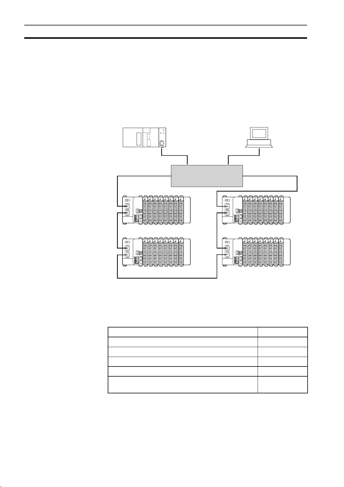
1-1 Overview of GRT1-series SmartSlice I/O Units
The GRT1-Series SmartSlice I/O Units are building-block style I/O Devices,
which can be expanded in small I/O increments. This provides the possibility
to configure I/O systems which exactly match the various customer
applications. SmartSlice I/O Units communicate with the PROFINET IO
Controller Unit by remote I/O communication through a PROFINET IO
Communication Unit. The figure below shows a typical I/O configuration.
Switch / MRP Manager
GRT1-series SmartSlice I/O
and PROFINET IO Units
2
Figure 1.1: GRT1-PNTs connected to an IO Controller through Profinet
The GRT1-Series of SmartSlice I/O Units, Communication Units and
PROFINET IO Units is constantly being expanded with new Units. Refer to the
following manuals.
/i
Name Manual Reference
GRT1 Series SmartSlice I/O Units Operation Manual W455
GRT1-DRT DeviceNet Communication Unit Operation Manual W454
GRT1-PRT PROFIBUS Communication Unit Operation Manual W04E
GRT1-CRT CompoNet Communication Unit Operation Manual W476
SYSMAC CJ-Series CJ1W-PNT21 PROFINET IO Controller
Unit Operation Manual
W12E
Page 15

GRT1-PNT PROFINET IO Communication Unit Section 1-2
1-2 GRT1-PNT PROFINET IO Communication Unit
1-2-1 Features
The GRT1-PNT PROFINET IO Communication Unit for SmartSlice I/O
controls data exchange between the PROFINET IO Controller and SmartSlice
I/O Units over the PROFINET IO network as an IO Device. For an overview of
the PROFINET IO technology refer to Appendix A PROFINET IO technology.
I/O Data Exchange Cyclic I/O data exchange is used to exchange I/O data between the
PROFINET IO Controller and SmartSlice I/O Units through the PROFINET IO
Communication Unit. In addition to I/O data, status information in the
PROFINET IO Communication Unit can be accessed from the PROFINET IO
Controller Unit.
FINS/UDP Interface The PROFINET IO Communication Unit is provided with a FINS/UDP
Interface. This enables not only the PROFINET IO Controller to access the
SmartSlice I/O Units using OMRON FINS messaging, but any device which
supports a UDP interface (such as a Personal Computer using CX-Server
Lite). This allows for configuration and monitoring of the
from remote stations.
SmartSlice I/O Units
Simplified Start-up The PROFINET IO Communication Unit can be set up easily, just by wiring the
Unit, configuring the PROFINET IO network using CX-ConfiguratorFDT and
making simple DIP switch settings. The Unit's configuration is read
automatically when the power is turned ON and I/O is also automatically
allocated in the SmartSlice I/O Units.
Device Name Store In
GRT1-END-M Memory End
Unit
Easy PROFINET IO
Network Layout
MRP Ring Redundancy To avoid a single network failure causing communication failure within a large
Facilitating IO Controller
Redundancy
The separately available GRT1-END-M Memory End Unit facilitates easy
replacement of the PROFINET IO Communication Unit. It optionally replaces
the standard GRT1-END End Unit. No re-configuration using CXConfiguratorFDT is required in case of replacement of the Communication
Unit. The PROFINET IO Device name, used for identification of the
Communication Unit on the PROFINET IO network, is backed up and restored
to and from the GRT1-END-M Memory End Unit.
The PROFINET IO Communication Unit is equipped with two ethernet ports.
The built-in ethernet switch functionality allows for easy line configuration of
the network, as additional external ethernet switches may not be necessary.
part of the network, the units can be set up in a ring topology. MRP Ring
Redundancy as specified in the PROFINET standards ensures
communication to all remaining devices through the redundant path.
To ensure a safe implementation of the application, the PROFINET IO
Communication Unit and the PROFINET IO Controller offer the possibility of
PLC system redundancy. Two IO Controllers (active and standby) are present
in a network connected to all I/O Devices. This feature ensures a fast change
from active to standby PLC / IO Controller in case of malfunction.
Simplified I/O Wiring All SmartSlice I/O Units that connect to a PROFINET IO Communication Unit
are equipped with screw-less clamp terminal blocks. Wiring to external I/O is
accomplished just by inserting the wire into the terminals, eliminating the need
to tighten terminal screws.
3
Page 16

GRT1-PNT PROFINET IO Communication Unit Section 1-2
Table Registration The configuration of the SmartSlice I/O Units (mounting order and I/O size)
connected to a PROFINET IO Communication Unit can be registered in a
table simply by setting a DIP switch. Once the table has been registered, the
actual configuration is compared to the registered configuration each time that
the power is turned ON. If the configuration does not match, a status flag is
turned ON in the PROFINET IO Controller to indicate the error.
On-line Replacement of I/O
Units
The SmartSlice I/O Unit's circuit section can be removed, so it is not
necessary to turn OFF the Communication Unit’s power to replace a Unit.
Communication can be maintained in the remaining (connected) Units.
Parameter Backup and
Restores
Before replacing a SmartSlice I/O Unit for maintenance, the parameter data
set in all SmartSlice I/O Units can be backed up in the PROFINET IO
Communication Unit by toggling a DIP switch. Another DIP selects the mode
to automatically write the back-up parameter data to the replacement
SmartSlice I/O Unit.
1-2-2 System configuration
The PROFINET IO Communication Unit connects to the IO Controller by an
Ethernet network cable and it connects to the SmartSlice I/O Units by directly
coupling the Units together.
I/O Data Exchange The I/O Unit data in the PROFINET IO Communication Unit is shared with the
IO Controller's Input and Output Areas through the PROFINET IO network.
The I/O Units' data is collected in the PROFINET IO Communication Unit and
exchanged with the IO Controller cyclically.
Messaging Services The GRT1-PNT PROFINET IO Communication Unit also supports messaging
services using FINS/UDP, allowing the user to send acyclic message
commands addressed to the GRT1-PNT Unit or individual SmartSlice I/O
Units. This can be sent from the PLC or for instance the Personal Computer.
End Unit for PROFINET IO Always install an End Unit on the last I/O Unit in the system. For the
PROFINET IO Communication Unit there are two options:
/i
Type I/O points Model number Description
End Unit -- GRT1-END End Unit to be mounted to the end of the
SmartSlice I/O Terminal.
Memory
End Unit
2 input bits GRT1-END-M End Unit to be mounted to the end of the
SmartSlice I/O Terminal.
The unit has a backup of the IO Device
Name of the Communication Unit.
In case of replacement of the PROFINET IO Communication Unit, the
PROFINET IO Device Name will be restored from the GRT1-END-M Unit to
the new Communication Unit. In case of the standard GRT1-END, additional
configuration download using CX-ConfiguratorFDT is required after
replacement.
Note 1 Unlike the standard End Unit, the Memory End Unit will count as one SmartSlice I/O
Unit. Up to 63 SmartSlice I/O Units can be connected to one PROFINET IO Communication Unit when the GRT1-END-M is used.
2 The GRT1-END-M Memory End Unit functionality only applies to the PROFINET IO
Communication Unit. Although the Memory End Unit has the basic End Unit funtionality, the Unit is not aimed to be used together with other Communication Units.
4
Page 17

GRT1-PNT PROFINET IO Communication Unit Section 1-2
1 2
Switch
Figure 1.2: A single GRT1-PNT connects to multiple I/O blocks via Turnback units.
1 Remote I/O data is collected from the connected SmartSlice I/O Units and
exchanged with the IO Controller Unit
2 Acyclic messages are used to monitor operation and write parameters to
the SmartSlice I/O Units.
5
Page 18

GRT1-PNT PROFINET IO Communication Unit Section 1-2
1-2-3 Specifications
Functional specifications
/i
Item Specification
Installation Unit type SmartSlice GRT1 series
Model GRT1-PNT
Mounting position DIN Rail mounted
Power supply 24 V
Current consumption 140 mA (max), 120 mA typical at 24 V
+ 10 % / − 15 % (20.4 VDC to 26.4 VDC)
DC
DC
Dimensions (WxHxD) 58 x 80 x 70 mm
Weight 120 g (typical)
Environment Ambient operating temperature −10 °C to +55 °C (no icing or condensation)
Ambient operating humidity 25 % to 85 % Relative Humidity
Storage temperature −40 °C to +70 °C (no icing or condensation)
Vibration resistance 150 m/s
2
Dielectric strength 500 VAC (between isolated circuits)
Conformance to EMC and
EN 61131-2:2003
Electrical safety standards
Front case DIP-switches 4 DIP switches on the front of the unit:
• Switch 1: Create / Enable registration table
• Switch 2: Not used
• Switch 3: Automatic restore
• Switch 4: Backup Trigger
Indicators 6 LEDs;
Unit status:
• RUN (green LED),
• ERR (red LED),
• UNIT PWR (green LED).
SmartSlice I/O Unit status:
• TS (red/green LED),
• I/O PWR (green LED).
PROFINET IO status:
• BF (red LED).
PROFINET IO Connector 2 x RJ45 8-pin Modular Connector
(conforming to ISO 8877)
Power Screwless push-in connectors
Unit power and I/O power are separated.
Field Ground connector Screwless push-in connector
6
Page 19

GRT1-PNT PROFINET IO Communication Unit Section 1-2
Item Specification
SmartSlice I/O System Number of connectable SmartSlice
I/O Units
Turnback cable Length 1 m, up to 2 cables can be connected.
SmartSlice I/O Unit connections Building-block style configuration (Units connect with Turn-
Base block power supply Voltage: 24 V
Event messaging Supported
64 units max. (including GRT1-END-M Memory Unit)
Connected directly to the GRT1-PNT or via turnback
extension units.
back cables)
DC
Current: 4 A max
Protocol specifications
/i
Item Specification
PROFINET interface Protocol PROFINET IO
PROFINET unit type PROFINET IO Device
Isochronous mode No
Alarms Yes
Minimum Update Rate 8 ms
Transfer specifications Bitrate 100 Mbps (100Base-TX)
Automatic detection of transmission speed Yes
PROFINET IO cable Type LAN balanced of category 5 or higher,
according to ISO/IEC 11801 Edition 2.0
Core cross section AWG 22
Maximum number of connector/socket pairs 6
Max transmission distance 100 m (distance between nodes)
PROFINET redundancy Protocol Media Redundancy Protocol (MRP) client
Configuration GSD file GSDML-V2.1-OMRON-GRT1-PNT-
20081205.xml
DTM Included in CX-ConfiguratorFDT
FINS service FINS/UDP Supported
7
Page 20
GRT1-PNT PROFINET IO Communication Unit Section 1-2
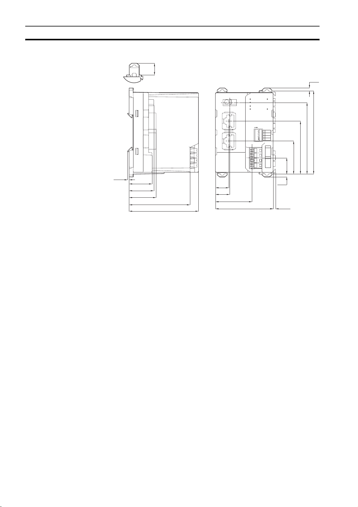
External dimensions
11. 75
2.85
OMRON
1.5
23.1
24.8
27.1
61.2
69.7
LNK1LNK2
13.5
14.3
GRT1-PNT
FG
PORT1PORT2
36.7
RUN
UNIT PWR
ERR
BF
TS
I/O PWR
ON
REGS
1
NC
2
3
ADR
BACK
4
UNIT
+V
-V
I/O
+V
-V
DC24V
INPUT
2.85
58 2.4
83.5
71.7
53.2
33.2
16.3
Figure 1.2.3: GRT1-PNT PROFINET IO Communication Unit external dimensions
8
Page 21
GRT1-END-M memory end unit Section 1-3
1-3 GRT1-END-M memory end unit
Functional specifications
/i
Item Specification
Installation Unit type SmartSlice GRT1 series
Model GRT1-END-M
Mounting position DIN Rail mounted
Current consumption 30 mA (max), 24 mA typical at 24 V
DC
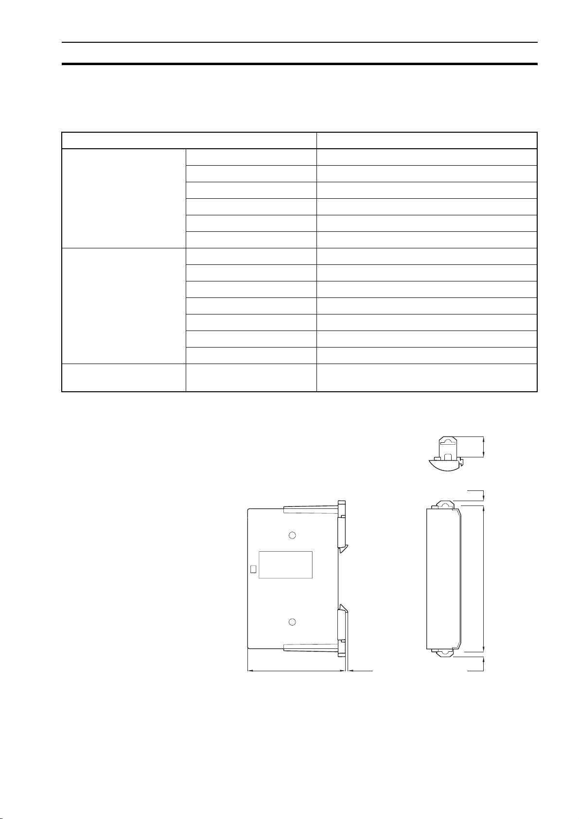
Dimensions (WxHxD) 19.5 x 83.5 x 55.7 mm
Weight 60 g (typical)
Environment Ambient operating temperature −10 °C to +55 °C (no icing or condensation)
Ambient operating humidity 25 % to 85 % relative humidity
Storage temperature −25 °C to +65 °C (no icing or condensation)
Noise immunity Conforms to IEC61000-4-4, 2.0 kV
Shock resistance 150 m/s
Dielectric strength 500 V
2
AC
Enclosure rating IP20
Front case Indicators TS (Two-colour LED):
indicates the unit’s operating status.
External dimensions
55.7 1.5
END-M
11. 75
2.85
TS
83.5
2.85
Figure 1.3: GRT1-END-M memory end unit external dimensions
9
Page 22

GRT1-PNT configuration Section 1-4
1-4 GRT1-PNT configuration
PROFINET IO
Configuration Means
GRT1-PNT Configuration
DTM
GRT1-PNT I/O
Configuration
The PROFINET IO Controller Unit requires a configuration before it can
exchange I/O data with any of its IO Devices. For this configuration information
on the IO device must be available. OMRON provides two means to facilitate
IO Controller Unit configuration.
• A GRT1-PNT DTM
• A GRT1-PNT GSD file
The GRT1-PNT DTM is an executable component, provided by OMRON,
which requires an FDT Container program like OMRON's CXConfiguratorFDT (see also Appendix A PROFINET IO technology, FDT/DTM
Technology). The DTM runs inside this FDT Container and provides its own
User Interface. It can access GRT1-PNT and SmartSlice I/O Unit data using
FINS/UDP and present that to the user. It can also save the settings, using the
features of the FDT Container program. The GRT1-PNT DTM provides the
user with the following features.
• PROFINET I/O Configuration
• Configuration of individual SmartSlice I/O Units
• Monitoring of the SmartSlice I/O System
The I/O Configuration User Interface allows the user to define the
configuration of SmartSlice I/O Units attached to the PROFINET IO
Communication Unit. It also allows the user to make parameter settings for
individual SmartSlice I/O Units.
The I/O Configuration is used by the PROFINET IO Controller Unit when
mapping the I/O data of individual SmartSlice I/O Units onto the PLC memory
areas. It is also sent by the PROFINET IO Controller Unit to the GRT1-PNT for
verification when establishing communication. The I/O Configuration sent by
the PROFINET IO Controller Unit must match the physical configuration
attached to the GRT1-PNT PROFINET IO Communication Unit, in order to
proceed with I/O data exchange.
Monitoring the SmartSlice
I/O System
Configuration via GSD File The GSD file concept is other way of configuration. The GSD file for the
Third-Party IO Controller
Units
The Monitoring User Interfaces allows the user to read information from
individual SmartSlice I/O Units. It also provides a means to read the Error Log
of the GRT1-PNT PROFINET IO Communication Unit.
GRT1-PNT is an XML-based file, which contains all options required to
configure a PROFINET IO Controller Unit. The file can be loaded by the
configuration software of the IO Controller Units, which will then present the
information to the user to allow the appropriate selections to be made.
The drawback of the GSD file is that - unlike the GRT1-PNT DTM - it only
provides setting options for configuring the PROFINET IO. The GSD file does
not provide the means to access data of the SmartSlice I/O Units directly.
The GSD file for GRT1-PNT can be used to configure most third-party I/O
Controller Units. The GRT1-PNT GSD file contains all the necessary
parameters to allow the user to configure the IO Controller Unit for I/O data
exchange.
10
Page 23

GRT1-PNT configuration Section 1-4
Note 1 The GRT1-PNT DTM can also be used in third-party configuration software pro-
vided that this software supports the FDT/DTM concept.
2 With the CX-ConfiguratorFDT FDT Container OMRON also provides a Generic IO
Device DTM, an FDT/DTM interface between the FDT Container program and GSD
files. Alternatively, this DTM can be used to set up an IO Controller Unit, using the
GRT1-PNT GSD file. This Generic IO Device DTM however, does not provide the
means to access data of the SmartSlice I/O Units directly.
Downloading the
configuration
After setting up the configuration, it must be downloaded to the PROFINET IO
Controller Unit. The download process depends on the IO Controller Unit
used.
11
Page 24

Basic operating procedure Section 1-5
1-5 Basic operating procedure
1-5-1 Overview
The following diagram provides an overview of the installation procedures. For
experienced installation engineers, this may provide sufficient information. For
others, cross-references are made to various sections of this manual where
more explicit information is given.
/i
Mount the GRT1-PNT PROFINET IO Unit and the
SmartSlice I/O Units including the GRT1-END-M Unit.
(See section 2-3 Installing the GRT1-PNT Unit).
T
Wire the GRT1-PNT PROFINET IO Communication Unit
and the SmartSlice I/O Units.
(See section 2-3 Installing the GRT1-PNT Unit).
T
Setup the PROFINET IO network.
(See section 2-4 Wiring the GRT1-PNT Unit).
T
Power up the GRT1-PNT and perform initial setup.
(See section 3-4 Set-up the GRT1-PNT Configuration).
T
Configure the PROFINET IO Controller Unit.
(See section 3-4 Set-up the GRT1-PNT Configuration).
T
PROFINET IO starts communicating, confirmed by the BF
LED being not lit. Check status of other LED Indicators.
(See section 3-5 Monitoring the GRT1-PNT).
12
Page 25

Basic operating procedure Section 1-5
1-5-2 Preparations for use
The following procedure shows the basic steps required before using the
PROFINET IO Communication Unit and the SmartSlice I/O Units.
Initial setup procedure 1 Mount the GRT1-PNT Unit and the SmartSlice I/O system on the DIN rail.
The maximum number of SmartSlice I/O Units can be 64 (including GRT1-
END-M End Unit).
2 Wire the SmartSlice I/O Units and the GRT1-PNT Unit's power supply.
3 Wire the PROFINET IO network, to connect the Communication Unit to the
PROFINET IO Controller Unit.
4 Turn ON the power to the Unit and the I/O.
5 Turn ON (from OFF to ON) DIP switch 1 on the front of the PROFINET IO
Communication Unit. When switch 1 is turned ON, the existing SmartSlice
I/O Unit configuration (connection order and I/O size) is registered in the
PROFINET IO Communication Unit as a registered table. After the table is
registered, leave pin 1 ON to enable the table.
Note The next time the power is turned ON, the actual SmartSlice I/O Unit configuration at
power on is automatically compared to the registered table. Any SmartSlice I/O Units
that do not match the registered table (connection order or I/O size) will not participate
in I/O communication. I/O communication will start with the other SmartSlice I/O Units.
Configuration procedure Use the following procedure to configure the IO Controller Unit together with
the PROFINET IO Communication Unit using CX-ConfiguratorFDT and the IO
Controller and IO Device DTMs:
1 Turn ON the PLC power supply and the power supplies of the IO Devices
on the network.
2 In CX-ConfiguratorFDT, create a network and define the parameters and
I/O configurations for the PROFINET IO Controller Unit settings and the
allocated IO Devices. Choose the update rate for each IO Device.
3 Use the PROFINET IO Controller DTM to assign Device Names to the
actual IO Devices in the network.
4 Download the network configuration to the PROFINET IO Controller Unit.
After downloading the configuration, CX-ConfiguratorFDT will restart the
PROFINET IO Controller Unit.
5 After restarting the PROFINET IO Controller Unit it will automatically start
communication when the PLC goes into RUN/MONITOR mode.
13
Page 26

Basic operating procedure Section 1-5
14
Page 27

SECTION 2
Installation and wiring
This section shows the GRT1-series PROFINET IO Communication Unit and identifies its controls and
indicators. It contains the procedures for installing and wiring the Communication Unit as well as the GRT1series SmartSlice I/O Units. It also contains the procedures for setting up the PROFINET IO network.
SECTION 2 Installation and wiring 15
2-1 GRT1-PNT unit components .................................................................................................................. 16
2-2 GRT1-END-M unit components ............................................................................................................. 22
2-3 Installing the GRT1-PNT Unit................................................................................................................. 23
2-4 Wiring the GRT1-PNT Unit..................................................................................................................... 28
2-5 Setting up the PROFINET IO Network................................................................................................... 32
2-6 Installation of Configuration Software .................................................................................................... 38
15
Page 28
GRT1-PNT Unit components Section 2-1
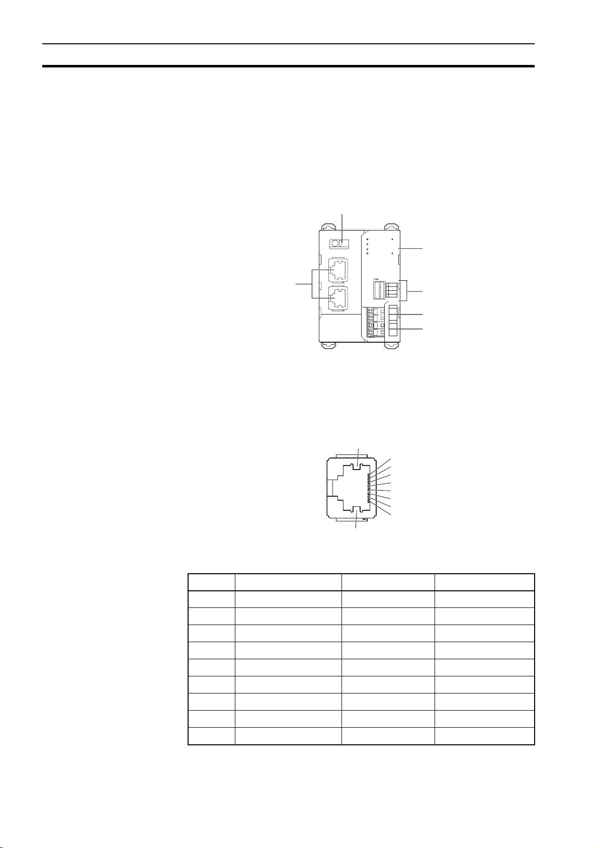
2-1 GRT1-PNT Unit components
2-1-1 Overview
The illustration below shows the two PROFINET IO Ethernet connectors with
Link activity LED indicators (1), the Status LED indicators (3), the Field Ground
Terminal (2), the DIP switches (4) and the power supply terminals (5 and 6) on
the front side of the PROFINET IO Communication Unit. Each of these
components is explained in the following sections.
2
OMRON
GRT1-PNT
FG
LNK1LNK2
PORT1PORT2
1
RUN
ERR
BF
TS
UNIT PWR
I/O PWR
ON
3
REGS
1
NC
2
3
ADR
BACK
4
UNIT
+V
-V
I/O
+V
-V
DC24V
INPUT
4
5
6
2-1-2 Ethernet connectors
The GRT1-PNT contains two Ethernet connector ports. The ports are
functionally the same and enable bus line network topology.
/i
Pin Signal Abbreviation Signal direction
1 Transmission data + TD+ Output
2 Transmission data - TD- Output
3 Reception data + RD+ Input
4 Not used --- ---
Figure 2.1: GRT1-PNT overview
9
1
2
3
4
5
6
7
8
9
Figure 2.1.2: GRT1-PNT ethernet connector
16
5 Not used --- ---
6 Reception data - RD- Input
7 Not used --- ---
8 Not used --- ---
9 Field Ground FG ---
Page 29
GRT1-PNT Unit components Section 2-1
The following standards and specifications apply to the connectors for the
Ethernet twisted-pair cable.
• Electrical specifications: Conforming to IEEE 802.3 standards
• Shielded twisted-pair (STP) cable: minimum category CAT5
• Connector structure: RJ45 8-pin Modular Connector (conforming to
ISO 877)
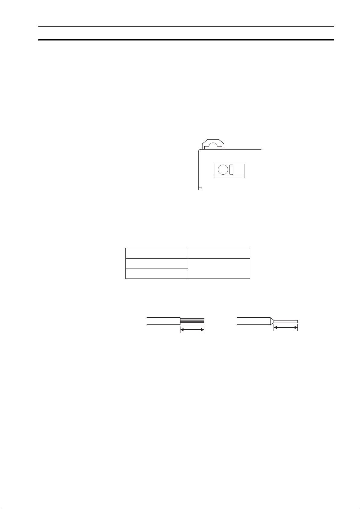
2-1-3 Field Ground Terminal
The GRT1-PNT PROFINET IO Communication Unit provides a Field gGround
Terminal at the front side.
OMRON
GRT1-PNT
FG
Figure 2.1.3: GRT1-PNT Field Ground Terminal
Recommended Wire
Strip Length
Pin Terminal Length
2-1-4 LED indicators
To help prevent electrical shock and/or if noise is a significant source of errors,
ground the Field Ground Terminal with a ground resistance of less than 100 Ω
using a 14-gauge wire (minimum cross-sectional area of 2 mm
/i
Type Gauge
Stranded wire 20 AWG to 14 AWG
Pin terminal
(0.5 to 2.0 mm
2
)
2
).
Strip wire between 8 mm and 10 mm of insulation at the ends of the wires
(stranded or solid wire) or use pin terminals with a pin (conductor) length of
8 mm to 10 mm.
Strip 8 to 10 mm.
Pin length: 8 to 10 mm
The GRT1-PNT PROFINET IO Communication Unit uses the following LED
indicators.
• Six LEDs to indicate status of the Unit and the PROFINET IO network
• Two LEDs at the Ethernet ports to indicate the Link activity of the ports
17
Page 30

GRT1-PNT Unit components Section 2-1
RUN
ERR
BF
TS
UNIT PWR
I/O PWR
RUN
UNIT PWR
ERR
BF
TS
I/O PWR
Figure 2.1.4: GRT1-PNT LED indicators
Status indicator
/i
specification
Indicator Colour Status Meaning
RUN
Unit status
ERR
Unit error
BF
PROFINET IO
failure
TS
SmartSlice I/O
system
communication
status
Green Not lit • Start-up test failed, unit not operational.
• Fatal error: Operation stopped.
Lit Initialization successful, unit is in normal operation.
Red Not lit Unit is in normal operation.
Flashing A start-up error has occurred.
Lit Fatal error in system execution.
Red Not lit • No PROFINET IO communication errors occurred.
• I/O data exchange in progress.
Flashing The configuration settings sent by the PROFINET IO Controller unit are
invalid. No I/O data exchange is possible.
Lit No PROFINET IO communication has been detected by the unit.
--- Not lit • No power supplied.
• Communication has not started with SmartSlice I/O Unit.
• Over current detected.
Green Flashing once
SmartSlice I/O Unit added to the system
per second
Flashing twice
per second
Backup/Restore function operating:
• Restoring settings to SmartSlice I/O Unit, backup function operating.
• Downloading SmartSlice I/O Unit settings.
Lit Communication with SmartSlice I/O Unit established.
Red Flashing Non-fatal communication error occurred:
• Communication time out.
• Verification error occurred with registered table.
• Different model Unit detected after SmartSlice I/O Unit replacement.
Lit for 2
seconds
Failure occurred while restoring settings to SmartSlice I/O Unit or
downloading SmartSlice I/O Unit settings.
Lit Fatal communication error occurred.
UNIT PWR Green Not lit Power supply to the Unit is not present (All other LED indicators are also
OFF).
Lit Power supply to the Unit is present.
I/O PWR Green Not lit Power supply to the SmartSlice I/O Unit is not present. The SmartSlice I/O
Units may be operative, but no output is available.
Lit Power supply to the SmartSlice I/O Unit is present.
18
Page 31

GRT1-PNT Unit components Section 2-1
Link activity specification /i
Indicator Colour Status Meaning
LINK Green Not lit No ethernet communication on corresponding port.
Lit Transmission/reception is in progress with connected switch/IO Controller
for corresponding port.
2-1-5 DIP switches
Four DIP switches on the front of the Communication Unit are provided for
operational settings. The factory setting is OFF for all DIP switches.
ON
1
REGS
NC
2
ADR
3
4
BACK
Figure 2.1.5: GRT1-PNT DIP switches
/i
DIP Switch Caption Description
1 REGS Create / Enable Registration Table
2 NC Not Used (Always OFF)
3 ADR Automatic Restore
4 BACK Backup Trigger
Note It is recommended to use the features that are made available by DIP switches 1, 3 and
4 (as discussed on the next page).
DIP Switch 1: REGS If DIP switch 1 is turned from OFF to ON while the Unit’s power is ON, the
existing SmartSlice I/O Unit configuration (connection order and I/O size) is
registered in the PROFINET IO Communication Unit as a registered table.
If DIP switch 1 is ON when the Unit’s power is turned ON, the actual
SmartSlice I/O Unit configuration at start-up is automatically compared to the
registered table. Any SmartSlice I/O Unit that does not match the registered
table will not participate in SmartSlice I/O communication.
/i
Switch 1 REGS Function
ON Registered table is enabled: if there is a verification error, the
affected Unit will not participate in communication.
OFF Registered table is disabled: all Units always participate in
communication.
OFF to ON Register I/O Unit table
(Unit Power must be ON)
ON to OFF Clear registered I/O Unit table
(Unit Power must be ON)
DIP Switch 2: NC DIP switch 2, marked NC, is not used and should always be set to OFF.
19
Page 32

GRT1-PNT Unit components Section 2-1
DIP Switch 3: ADR When DIP switch 1 is ON (registered table enabled) and DIP switch 3 is
switched to ON, parameter data is automatically restored to the SmartSlice
I/O Units that had parameter data backed up.
/i
Switch 3 ADR Function
OFF Automatic restore function disabled.
OFF to ON Automatic restore function enabled (when pin 1 is ON).
DIP Switch 4: BACK When DIP switch 1 is ON (registered table enabled) and DIP switch 4 is turned
OFF to ON, the parameter data of all connected SmartSlice I/O Units is
backed up in the Communication Unit.
/i
Switch 4 BACK Function
ON Switch ON to OFF to ON to start the parameter backup (when
DIP switch 1 is ON).
OFF ---
max 3 s
ON OFF ON
The backup operation starts after DIP switch 4 is
turned from ON to OFF to ON within 3 seconds.
20
Page 33

GRT1-PNT Unit components Section 2-1
2-1-6 Power supply connector
The PROFINET IO Communication Unit has two 24 VDC power supply
terminals on the front of the Unit.
Holes for wires
(pin terminals)
System Power supply terminals
External I/O Power supply terminals
/i
Power supply terminals Function
System These terminals supply power to the internal circuits of
both the PROFINET IO Communication Unit and the
connected SmartSlice I/O Units (through the SmartSlice
bus).
External I/O These terminals supply power to the external I/O that is
connected to the connected SmartSlice I/O Units.
24 VDC
24 VDC
Release button
Both the SmartSlice I/O System power supply and the external I/O power
supply are connected with screwless clamping-type terminals.
Note System power supply and External I/O power supply are not transferred through the
GCN2-100 Turnback cable. The GRT1-TBR Right Turnback Units provide the same set
of Power Supply terminals as the PROFINET IO Communication Unit.
21
Page 34

GRT1-END-M Unit components Section 2-2
2-2 GRT1-END-M Unit components
2-2-1 Overview
The illustration below shows the front view of the GRT1-END-M with the TS
LED indicator (1).
END-M
TS
1
2-2-2 LED Indicators
Figure 2.2.1: GRT1-END-M overview
The GRT1-END-M Memory End Unit uses a single LED indicator to indicate
SmartSlice I/O Unit status.
the
END-M
TS
Figure 2.2.2: GRT1-END-M LED indicators
/i
Name Colour Status Meaning
TS Green Lit Normal status Normal unit status.
Normal network status.
Flashing Operating The automatic restore / backup
function is operating.
Red Lit Fatal error Unit hardware error (EEPROM error
or WDT error)
22
Flashing Non-fatal error Communication time out, etc.
--- Not lit No power • Unit power supply if OFF.
• Unit is waiting for initialization.
• Unit is being reset.
Page 35

Installing the GRT1-PNT Unit Section 2-3
x10x1x1
BUS
ON
+V
+V
-V
UNIT
DC24V
INPUT
REGS
NC
ADR
BACK
RUN
ERR
BF
TS
UNIT PWR
I/O PWR
2-3 Installing the GRT1-PNT Unit
2-3-1 Handling precautions
When installing the PROFINET IO Communication Unit and the SmartSlice I/O
Units, observe the following handling precautions.
• Always turn OFF the power supply to the PROFINET IO Communication
Unit, the SmartSlice I/O Units and the external I/O, before mounting or
dismounting a Unit or connecting or disconnecting cables.
• Do not connect or disconnect the PROFINET IO Communication Unit’s
communication cable while the PROFINET IO network is operating.
• Ensure that the power supplies for the PROFINET IO Communication Unit,
the SmartSlice I/O Units and the external I/O are wired correctly.
• Provide separate conduits or ducts for the control lines to prevent noise
from high-tension lines or power lines.
The SmartSlice I/O system is installed and set up as a PROFINET IO Device.
A PROFINET IO communication cable connects the PROFINET IO
Communication Unit and the IO Controller. Up to 64 SmartSlice I/O Units can
be connected to one GRT1-PNT Unit.
PROFINET
IO Controller
PROFINET
Communication Unit
OMRON GRT1-PRT
RUN
UNIT PWR
5
5
6
6
4
4
7
7
3
3
8
8
ERR
2
2
9
9
1
1
0
0
BF
x10
TS
I/O PWR
ON
BUS
24 VDC
for Unit
24 VDC
for I/O
Slide SmartSlice I/O Units
in from the front to install.
REGS
1
NC
2
ADR
3
BACK
4
UNIT
+V
-V
I/O
+V
-V
DC24V
INPUT
SmartSlice I/O Units (64 max.)
2-3-2 Installation on a DIN Rail
The GRT1-PNT and SmartSlice I/O Units must be mounted on a DIN Rail.
Attach the DIN Rail with screws in every third mounting hole.
Attach the track with screws at a
maximum spacing of 105 mm
between adjacent screws.
23
Page 36

Installing the GRT1-PNT Unit Section 2-3
SmartSlice I/O System
The system can be mounted in any of the following 6 directions.
Orientation
Note Please note the vertical orientations are not recommended because the heat dissipa-
tion may limit product life time.
Installing a unit To install a PROFINET IO Communication Unit on the DIN Rail, press the Unit
onto the DIN Rail from the front. Press the Unit firmly until it clicks, indicating
that the Unit’s DIN Rail Mounting Hooks have all locked onto the DIN Rail.
When the Unit is pushed onto the DIN Rail,
verify that the Mounting Hooks have locked.
Mounting Hooks
Press firmly towards the DIN Rail.
Press firmly until you hear a click,
indicating that the Mounting Hooks
have locked.
Removing a unit Use a standard screwdriver to release the DIN Rail Mounting Hooks at the top
and bottom of the Unit and pull the Unit straight away from the DIN Rail.
24
Page 37

Installing the GRT1-PNT Unit Section 2-3
g
2-3-3 Connecting the PROFINET IO Unit and SmartSlice I/O Units
Connect the first SmartSlice I/O Unit to the PROFINET IO Communication
Unit by aligning the sides of the Units and sliding in the SmartSlice I/O Unit
from the front. Insert the Unit until it clicks, indicating that the Unit has locked
onto the DIN Rail. Normally it is not necessary to release the Unit’s mounting
hooks when mounting the Unit.
Slide the Slice I/O Unit toward the DIN Track from
the front. Insert the Unit until you hear a click,
which indicates that the Unit has locked on the Track.
It is normally not necessary to release the DIN Track
mounting hook when mounting the Unit.
Caution
Do not touch the connector on the Unit’s base block.
2-3-4 Connecting additional SmartSlice I/O Units
Connect additional SmartSlice I/O Units by aligning the sides of the Units and
sliding in the next Unit from the front. Insert each Unit until it clicks, indicating
that the Unit has locked onto the DIN Rail. Normally it is not necessary to
release the Unit’s mounting hooks when mounting the Unit.
Up to 64 SmartSlice I/O Units can be connected to one PROFINET IO
Communication Unit.
Slide the Unit to the DIN Track from the front.
Insert the Unit until you hear a click, which indicates
that the Unit has locked on the Track.
It is normally not necessary to release the DIN Track
mountin
hook when mounting the Unit.
25
Page 38

Installing the GRT1-PNT Unit Section 2-3
(
)
(
)
Connecting Turnback Units When a SmartSlice I/O System is divided into blocks, connect a GRT1-TBR
Right Turnback Unit to the right end of the first block and connect a GRT1-TBL
Left Turnback Unit to the left side of the expansion block. Mount these
Turnback Units on the DIN Rail in the same way as the SmartSlice I/O Units.
Use a GCN2-100 Turnback Cable to connect the Turnback Units together.
Mount additional SmartSlice I/O Units on the expansion block.
Turnback Cable connectors
GRT1-TBR Turnback Unit
for right side of block
GRT1-TBL Turnback Unit
for left side of block
Note The Turnback Units can be used to divide a SmartSlice I/O System into up to three
blocks.
Connecting an End Unit At the end of the last block, mount a GRT1-END End Unit or a GRT1-END-M
Memory End Unit. Mount the Unit on the DIN Rail in the same way as the
SmartSlice I/O Units.
GRT1-END End Unit
26
Page 39

Installing the GRT1-PNT Unit Section 2-3
x10x1x1
BUS
ON
+V
+V
-V
DC24V
INPUT
REGS
NC
ADR
BACK
RUN
ERR
BF
TS
UNIT PWR
I/O PWR
Mounting End Plates Always secure the SmartSlice I/O System on the DIN Rail by installing End
Plates on both sides of the System.
1 First hook the bottom of the End Plate on the bottom edge of the DIN Rail.
2 Attach the top of the End Plate, and pull the End Plate down onto the top
edge of the DIN Rail.
3 Tighten the End Plate’s securing screw.
End Plate
OMRON GRT1-PRT
5
6
4
3
2
9
1
0
x10
BUS
End Unit
RUN
UNIT PWR
5
6
4
7
7
3
8
8
ERR
2
9
1
0
BF
TS
I/O PWR
ON
REGS
1
NC
2
ADR
3
BACK
4
+V
-V
+V
-V
DC24V
INPUT
End Plate
2
1
27
Page 40

Wiring the GRT1-PNT Unit Section 2-4
2-4 Wiring the GRT1-PNT Unit
2-4-1 Connecting the SmartSlice I/O System Power Supply
The GRT-PNT PROFINET IO Communication Unit has two sets of power
supply terminals. See section 2-1-6 Power supply connector.
The following wiring example shows how power can be supplied to the various
units in the SmartSlice I/O system.
I/O
power
supply
I/O
(IN)
I/O
(AD)
PROFINET
Communication Unit
CPU
Connector
Power supply
(24 VDC)
I/O
power
supply
GRT1-TBL Turnback Unit (Left)
GRT1-PD2 I/O Power Supply Unit
I/O
(IN)
I/O
(AD)
I/O
(OUT)
I/O
power
supply
I/O
I/O
(AD)
(AD)
(AD)
(OUT)
I/O
I/O
I/O
(OUT)
(OUT)
End Unit
Fig. 2-4-1 Wiring example
GRT1-TBR Turnback Unit (Right)
I/O
I/O
(OUT)
Connector
Power is not supplied through
the Turnback Cable.
Do not exceed 80 W
power consumption
in one block.
Do not exceed 80 W
power consumption
in one block.
Evaluating the Power Supply Requirements
Unit Power Supply The maximum power consumption for SmartSlice I/O Units is 80 W per block.
1,2,3... 1 Calculate the power consumption of all SmartSlice I/O Units connected to
the PROFINET IO Communication Unit (including other Units like Turnback
Units and End Unit). Refer to the GRT1 Series SmartSlice I/O Units
Operation Manual (W455) for the power value for each SmartSlice I/O Unit.
2 If the power consumption exceeds 80 W, mount a Right Turnback Unit
(GRT1-TBR) on the SmartSlice I/O Unit at the point where the power
consumption still is less than 80 W.
3 Connect the 24 V
Unit power supply to the Left Turnback Unit (GRT1-
DC
TBL) of the next expansion block.
Note 1 The GRT1-TBL is equipped with separate power supply terminals for the Unit power
supply and I/O power supply.
2 When dividing the supply power, always wire (supply) the power from the
same power supply, as shown in the wiring example above.
28
Page 41

Wiring the GRT1-PNT Unit Section 2-4
I/O Power Supply The maximum I/O current consumption is 4 A.
1,2,3... 1 Calculate the total current consumption used by all external I/O of the
connected SmartSlice I/O Units (including other Units like the Memory End
Unit). Refer to the GRT1 Series SmartSlice I/O Units Operation Manual
(W455) for the (maximum) current value for each SmartSlice I/O Unit.
2 If the current consumption exceeds 4 A or you want to provide separate
systems for inputs and outputs, divide the SmartSlice I/O Units at the
desired point with a GRT1-PD2 I/O Power Supply Unit and provide a
separate external I/O power supply.
3 It is also possible to provide a separate external I/O power supply at a Left
Turnback Unit (GRT1-TBL).
Note 1 The GRT1-TBL is equipped with separate power supply terminals for the Unit power
supply and I/O power supply.
2 Always use isolated power supplies for the power supplies.
3 Power is not supplied through the GCN2-100 Turnback Cable from one block to the
next, as shown in the wiring example above.
2-4-2 Wiring Methods
Connect the power supply wires (24 VDC) to the PROFINET IO
Communication Unit’s screwless clamping power supply terminals. Apply pin
terminals to the wire ends before inserting them in the wire terminals.
Recommended Power
Supplies
Recommended Wire
Strip Length
Pin Terminal Length
Use a SELV power supply with over current protection.
A SELV power supply has redundant or increased insulation between the I/O,
an output voltage of 30 V
and a 42.4 V
RMS
or maximum of 60 VDC.
peak
Recommended power supply: S82K-01524 (OMRON) or S8TS-06024
(OMRON).
/i
Type Gauge
Stranded wire 20 AWG to 16 AWG
Solid wire
Pin terminal
(0.5 to 1.25 mm
2
)
Strip wire between 7 mm and 10 mm of insulation at the ends of the wires
(stranded or solid wire) or use pin terminals with a pin (conductor) length of
8 mm to 10 mm.
Strip 8 to 10 mm.
Pin length: 8 to 10 mm
29
Page 42

Wiring the GRT1-PNT Unit Section 2-4
Supplying Power to the
Units
Holes for wires
(pin terminals)
Release button
Press the release button with
a screwdriver and pull out the
wire (pin terminal).
Supplying I/O Power
These terminals supply power to both
the PROFINET Communication Unit's
internal circuits and the connected
SmartSlice I/O Units' internal circuits.
24 VDC
The upper two terminals supply power to the internal circuits of the PROFINET
IO Communication Unit and of the connected SmartSlice I/O Units.
Holes for wires
(pin terminals)
These terminals supply power to the
external I/O devices connected to the
SmartSlice I/O Units.
Release button
Press the release button with
a screwdriver and pull out the
wire (pin terminal).
24 VDC
The lower two terminals supply power to the external I/O Devices connected to
the SmartSlice I/O Units.
Note The GRT1-TBL Left Turnback Unit and GRT1-PD2 I/O Power Supply Unit have the
same screwless clamping power supply terminals as the PROFINET IO
Communication Unit. These terminals are wired in the same way as the PROFINET IO
Communication Unit’s terminals, by inserting the power supply wires.
Removing Wires To remove the wires press the release button above the terminal hole using a
slotted precision screwdriver and pull out the wire.
30
Page 43

Wiring the GRT1-PNT Unit Section 2-4
x10x1x1
BUS
ON
+V
-V
UNIT
DC24V
INPUT
REGS
NC
ADR
BACK
RUN
ERR
BF
TS
UNIT PWR
I/O PWR
2-4-3 Connecting the Turnback units
When a SmartSlice I/O System is divided into blocks to expand the system,
connect the GRT1-TBR Right Turnback Unit of one block to the GRT1-TBL
Left Turnback Unit of the next block with a GCN2-100 Turnback Cable, as
shown in the following diagram. A single PROFINET IO Communication Unit
can be expanded with up to two additional blocks, connected with two
Turnback Cables (2 m total).
GRT1-TBR Turnback Unit
OMRON GRT1-PRT
RUN
UNIT PWR
5
5
6
6
4
4
7
7
3
3
ERR
8
8
2
2
9
9
1
1
0
0
BF
TS
I/O PWR
x10
ON
BUS
REGS
1
NC
2
ADR
3
BACK
4
UNIT
+V
-V
DC24V
INPUT
GCN2-100 Turnback Cable
GRT1-TBL Turnback Unit
Insert the cable's connector fully
until it clicks, which indicates that
the connector's top and bottom
latches have locked.
Insert each cable connector fully until it clicks, which indicates that the
connector’s top and bottom latches have locked.
Note The GCN2-100 Turnback Cable does not propagate supply power from one block to the
next one. Always wire (supply) the power to the GRT1-TBL Left Turnback Unit from the
same power supply that supplies the PROFINET IO Communication Unit.
31
Page 44

Setting up the PROFINET IO network Section 2-5
2-5 Setting up the PROFINET IO network
2-5-1 Network structure
Various configurations are possible.
When connecting GRT1-PNT unit within a network, the following precautions
apply:
- Please be aware any additional Ethernet communication may influence the
PROFINET IO Communication.
- It is recommended to separate the PROFINET IO network from the other
(IT) network.
- Severely overloading the built-in Ethernet switch with traffic may cause the
switch to temporarily block the ports, interrupting all traffic including
PROFINET IO communication.
2-5-1-1 Line
A line topology consists of placing multiple IO Devices in series. Many IO
Devices, such as the GRT1-PNT Unit, have an ethernet switch integrated in
the Unit. This creates an easy way to connect the IO Devices.
Switch
Benefits:
• For bigger networks this topology implies lower cabling effort.
• This is a traditional field bus structure (compare PROFIBUS-DP).
• The Ethernet Switch is optional.
Disadvantages:
• Communication paths through many switches affect transmission times.
• A malfunction of a single integrated device will result in disconnecting part
of the network.
/i
Part Recommendation
Switch (optional) Industrial Ethernet Switch (either managed or unmanaged).
32
Page 45

Setting up the PROFINET IO network Section 2-5
2-5-1-2 Star
The star topology is the standard-most topology for Ethernet networks. A
central switch will allow communication to all individually attached devices.
Switch
Benefits:
• Flexible adding and removing devices without interrupting the network.
• Easy monitoring and diagnostics of the network.
Disadvantages:
• Cabling effort.
• Error state of switch will fail complete network.
/i
Part Recommendation
Switch Industrial Ethernet Switch (either managed or unmanaged).
33
Page 46

Setting up the PROFINET IO network Section 2-5
2-5-1-3 Tree
The tree topology is a hierarchial combination of multiple star topologies
interconnected with each other.
Switch
Switch
Benefits:
• Shorter data communication at local node. Avoiding excessive traffic
through a single switch.
• Hierarchy enables better transparency of the network
Disadvantages:
• Cabling effort.
• Error state of switch will fail complete network.
/i
Part Recommendation
Switch Industrial Ethernet Switch (either managed or unmanaged).
34
Page 47

Setting up the PROFINET IO network Section 2-5
2-5-1-4 Ring
The ring topology is achieved by closing both ends of a line. A network
redundancy ring protocol such as MRP (see section 2-5-2 MRP Ring
Redundancy) will provide a method of monitoring the state of the network and
switch the communication path in case of problems.
Switch / MRP Manager
Benefits:
• Malfunction of a single switch / IO Device will not result in disconnecting
part of the network. The network redundancy mechanism will automatically
maintain the connection with the other devices.
/i
Part Recommendation
Switch Industrial Ethernet Switch supporting MRP manager protocol. Suggestion:
Hirschmann Automation and Control GmbH, Series RS20/30/40, Software
Version 4 or higher.
2-5-2 MRP Ring Redundancy
The internal Ethernet Switch in the GRT1-PNT Unit supports the Media
Redundancy Protocol (MRP). This protocol, which is part of the PROFINET IO
Specification, enables the Unit to be part of a ring-shaped network structure.
This ring network structure will give network redundancy.
In case one of the line connections fails, the MRP ensures communication to
all IO Devices remains possible through the redundant path. The ring structure
can contain up to 50 Units and typically switches to the redundant path within
150 ms (max 500 ms).
The network requires an MRP manager to facilitate the redundancy. As an
MRP client, there are no specific settings required for the GRT1-PNT Unit.
Please refer to the manual of the used MRP manager unit for details on how to
set up and operate the MRP network.
35
Page 48

Setting up the PROFINET IO network Section 2-5
Switch Switch Switch
In case a connection fails, MRP Ring Redundancy ensures communication to
all devices through the alternative path.
2-5-3 PROFINET IO Controller redundancy
The PROFINET IO Controller redundancy feature ensures seamless changeover of active PLC / IO Controller to the standby PLC / IO Controller in case of
malfunction. To support the PROFINET IO Controller redundancy, a
redundancy Function Block can be downloaded from the OMRON website.
Both the active as the standby IO Controller have data exchange with all IO
Devices in the network. Only the active IO Controller is in control of the output
of the IO Devices.
In case of malfunction of the active IO Controller, the Function Block will
transfer control to the standby PLC system. In order to avoid momentary
changes in output data during this control change, the Data Hold parameter
should be set high enough for the standby IO Controller to take over. This
value should be determined experimentally.
For details about setting the PROFINET IO Controller redundancy refer to
PROFINET IO Controller manual (W12E).
Switch
36
Page 49

Setting up the PROFINET IO network Section 2-5
2-5-4 Establishing the PROFINET IO network
This section describes how to create, connect to and configure the PROFINET
IO network using the CX-ConfiguratorFDT software and the Device DTMs.
1 Select the Network Components (see previous section) and build network.
2 Connect the Personal Computer to the ethernet network.
- The PROFINET Scan Tool to assign the IO Device names can only
operate connected to the ethernet network.
- The parameter settings and monitoring of the GRT1 Slice I/O Units is
done directly on the ethernet network.
3 Start the CX-ConfiguratorFDT software. Install the appropriate GSD files
and DTMs for the connected IO Devices.
4 Configure the system to communicate with PLC / Profinet IO Controller.
Add the PROFINET IO Controller as parent to the network.
• Set IP address in DTM.
• Set IP address in on-line by using the Network Scan View.
• Confirm the on-line connection by putting the DTM on-line.
5 Build up the network within CX-ConfiguratorFDT. Add the IO Devices to the
Tree of the network by drag-dropping from the Device Catalogue. Assign
the modules for each individual IO Device.
6 Allocate the modules of the IO Devices to the intended PLC memory areas.
7 Download the configuration to the Unit.
8 Confirm proper operation. Checking the Monitoring GUI of DTM and LED
status of the Unit.
37
Page 50

Installation of Configuration Software Section 2-6
2-6 Installation of Configuration Software
In order to operate the GRT1-PNT and the SmartSlice I/O system the
PROFINET IO Controller needs to be configured for communication with the
GRT1-PNT. For this purpose OMRON provides the GRT1-PNT DTM via the
OMRON web site http://www.omron-industrial.com/
After installation the DTM will run in the FDT Container, allowing the user to
set up the I/O configuration and set the parameters of the GRT1-PNT and of
the individual SmartSlice I/O Units.
2-6-1 Installation requirements
The following are the minimum requirements for a PC to install the GRT1-PNT
DTM configuration software:
• PC Pentium III or higher, 500 MHz minimum
• Operating System: Windows 2000 SP2 or Windows XP
• RAM: 256 MB minimum
• Hard disk space: 256 MB minimum
• Graphics resolution: 1024 x 768 pixels minimum
• Installed FDT Container software, e.g. OMRON’s CX-ConfiguratorFDT.
2-6-2 Installation procedure
DTM Installation This section explains how to install the SmartSlice I/O Coupler DTM software.
1,2,3... 1 Exit all other Windows-based programs.
2 Double-click the file SmartSlice_IO_Coupler_Setup.exe.
The setup program for the GRT1-PNT DTM will start.
Select the preferred Language for the Setup and click OK.
3 The user is then guided through the installation process.
38
Page 51

Installation of Configuration Software Section 2-6
Pressing the Next button will start the installation.
4 When done, the installation program will notify the user of its completion.
The update of the Device Catalogue of the FDT Container is required
Updating the Device
Catalogue
After installation of the GRT1-PNT DTM the Device Catalogue in the FDT
Container needs to be updated, to show the new GRT1-PNT DTM in the list of
available devices. For CX-ConfiguratorFDT the following procedure applies.
1,2,3... 1 Open the Device Catalogue window in CX-ConfiguratorFDT.
2 Press the Update button to initiate the update sequence.
After updating, the GRT1-PNT DTM will be shown in the list of available
devices. It can now be used to setup a PROFINET IO network and configure
the Controller Unit.
Note In case the required PROFINET IO Controller DTM has not been installed, this needs
to be done first to allow the full features of the GRT1-PNT DTM to be used.
39
Page 52

Installation of Configuration Software Section 2-6
2-6-3 GRT1-PNT GSD File
Apart from the GRT1-PNT DTM, OMRON provides a GSD file to allow
configuration of third-party PROFINET IO Controller Units, which do not
provide an FDT Container.
The GSD file - GSDML-V2.1-OMRON-GRT1-PNT-20081205.xml - is
available through the OMRON Web site http://www.omron-industrial.com/
Section 3-4-3 Set-up using the GSD file discusses the configuration of the
PROFINET IO CX-ConfiguratorFDT using this GSD file.
Using the GSD file for configuration allows the user to configure the Controller
Unit for I/O data exchange with the GRT1-PNT and the SmartSlice I/O
System. It does not however, provide the acyclic messaging capabilities to
access parameters and status information in individual SmartSlice I/O Units.
The GRT1-PNT DTM does provide this capability.
The next section will discuss the features of the GRT1-PNT in detail as well as
how to set up, configure and operate the SmartSlice I/O System in a
PROFINET IO network.
40
Page 53

SECTION 3
Set-up and operation
This section describes the operational aspects of the GRT1-PNT and the SmartSlice I/O System. It first
discusses the operational features which can be used, prior to describing how to set up the system and how to
operate and monitor it on a PROFINET IO network.
SECTION 3 Set-up and operation 41
3-1 Device name setting and I/O allocation.................................................................................................. 42
3-2 Unit functions ......................................................................................................................................... 46
3-3 GRT1-END-M unit functions .................................................................................................................. 52
3-4 Set-up the GRT1-PNT Configuration ..................................................................................................... 54
3-5 Monitoring the GRT1-PNT ..................................................................................................................... 61
3-6 I/O communication characteristics ......................................................................................................... 64
41
Page 54

Device name setting and I/O allocation Section 3-1
3-1 Device name setting and I/O allocation
In order to identify the PROFINET IO Communication Unit on the PROFINET
IO network, it needs to be assigned a PROFINET IO Device Name. This
Device Name is an ASCII string, which is written to the IO Devices by the
PROFINET IO Controller DTM or configurator. Using the Device Name the
PROFINET IO Controller can configure parameter settings and establish I/O
Data Exchange.
For the OMRON PROFINET IO Controller the IO Device is also assigned an
IO Device Number. This number is used for the Device-related status and for
the acyclic (FINS) communication to the IO Device. This IO Device number is
set for each IO Device in the IO Controller DTM and is part of the configuration
downloaded to the IO Controller Unit.
Similarly, the individual SmartSlice I/O Units need a unique address to identify
each of them to the GRT1-PNT Unit. Contrary to the GRT1-PNT Unit, the
individual SmartSlice I/O Unit addresses are assigned automatically at startup.
3-1-1 Device name setting
For the OMRON CJ1W-PNT21 PROFINET IO Controller, the Device Names
are set using the Network Scan View:
42
The actual IO Device can be distinguished either by the MAC address printed
on the Unit or the Flash or Signal function of the Scan Tool. This function
flashes the indicator LEDs for 3 seconds, identifying the Unit on the rack.
Note 1 Be sure to have unique Device names for each of the IO Devices in the network. As
the name is used as identification, duplicate names will result in communication
failure.
2 It is not required to set IP addresses directly to the IO Device using the Scan Tool.
The addresses are set by the IO Controller at startup. Please define the specific IP
addresses in the IO Controller configuration.
3 The Device Name should comply to the PROFINET naming rules, for instance no
CAPS are used. This is checked by the Scan Tool.
Page 55

Device name setting and I/O allocation Section 3-1
3-1-2 Device number setting
The Device Number setting for each IO Device is used for the Device-related
status in PLC CIO memory and for the acyclic (FINS) communication to the IO
Device. This IO Device number is set in the IO Controller DTM and is part of
the configuration downloaded to the IO Controller Unit.
3-1-3 SmartSlice I/O Unit number allocation
The SmartSlice I/O Unit numbers are used to identify the individual SmartSlice
I/O Units in the SmartSlice I/O system. These unit numbers are assigned
automatically at start-up, when the power is turned ON. The numbering starts
from #1 and runs from left to right. It is not necessary for the user to set these
numbers.
PROFINET
Communication Unit
Note 1 The presence of Turnback units and cables does not influence the automatic
allocation of Unit numbers.
2 The unit numbers allocated automatically to the SmartSlice I/O Units are not related
to the PROFINET IO Addressing.
I/O
#1
The SmartSlice I/O unit numbers are assigned
automatically in order, from left to right.
I/O
#2
I/O
#3
I/O
#4
I/O
:
:
#64
43
Page 56

Device name setting and I/O allocation Section 3-1
pp
3-1-4 SmartSlice I/O allocation to the GRT1-PNT unit
The SmartSlice I/O Units’ I/O data is mapped on the I/O memory of the GRT1PNT, from which it is transferred to the PROFINET IO Controller unit. This
allocation is done automatically and determined by the SmartSlice I/O Unit’s
type. The figure below shows this mapping.
I/O memory
A
A
0
BC
(1) Communication Unit
(2) Each SmartSlice I/O Unit's I/O
data.
(3) SmartSlice I/O Unit
network participation
status.
D
E
Connected order
I/O Data is mapped in the order in which
the Units are connected, from low to high.
I/O Units with bit allocation are mapped from
the rightmost to leftmost bit, in 2-bit units.
I/O Units with word allocations are mapped
from the low to high word address
16
Order of allocation
8
CD
B
E
PROFINET
Communication
Unit
SmartSlice I/O Units
Note 1 One block of mapped Output data (from the Controller Unit) and one block of
mapped Input data are maintained in the GRT1-PNT and transferred to/from the
Controller Unit.
2 The first Input data word always contains the SmartSlice I/O Status word.
3 The GRT1-END-M End Unit must be configured in the SmartSlice I/O allocation. It
contains two input bits and should be allocated to the last slot of the configuration.
4 Bit-sized SmartSlice I/O Units, e.g. GRT1-ID4, GRT1-OD4 are grouped together in
words. They are mapped from the right-most bit to the left-most bit, in 2-bit units.
5 Word-sized SmartSlice I/O Units, e.g. GRT1-AD2, GRT1-DA2V are mapped to one
or more words, from the low to the high word address.
6 Total size of mapped I/O data can be 64 words output and 64 words input.
I/O Allocation Example I/O data is mapped to the GRT1-PNT Units I/O data blocks in the same order
the SmartSlice I/O Units are connected to the PROFINET IO Communication
Unit, regardless of the I/O Units’ models.
The example below shows the I/O data mapping to the Input / Output blocks.
#6
#5
#4
#3
ID4
AD2
OD4
ROS2
Word
First word Unused
Output area
15 8
#6 #5
Word
First word
+1
+2
+3
Input area
15 8
Communication Unit status
Unused
#4
#2
Communication
Unit
0
#1 #3 #2
#1
ID4
ID4
0
Some areas may be unused
when data is ma
ed.
44
Page 57

Device name setting and I/O allocation Section 3-1
The following example shows the mapping of Output Units.
SmartSlice I/O Unit configuration
Allocated Data Size
Communications
Unit
/i
Word
+0
+1
+2
+3
#1
OD4
#2
OD4
15
#3
OD4
#4 #5
Unused
#4
ROS
Data is allocated in 2-bit units
to I/O Units which require 4 bits.
There may be unused areas
as shown in the following table.
8
#6
#5
OD4
2
#2 #3
#6
DA2V
0
#1
#5
Data type Data size
I/O data (input and output) GRT1-ID4(-1) / GRT1-OD4(-1): 4 bits per Unit.
GRT1-ROS2: 2 bits.
GRT1-DA2V/DA2C: 2 words output data e.g.
Communication Unit status flags 1 word
SmartSlice I/O Unit communication
participating/withdrawn flags
Participating flags: 4 words
Withdrawn flags: 4 words
Tota l : 8 wo r d s
Communication Unit’s
Status Flags
I/O data (inputs) + Communication
Amount of I/O data being used + 1 word
Unit status flags
These flags can be used to monitor the status of the connection between the
GRT1-PNT and the SmartSlice I/O Units as well as the status of the
SmartSlice I/O Units themselves. The status flags take up 1 word and the
information is transferred to the Controller as part of the Input data. Please
refer to 3-5-1 Communication Unit's Status Flags.
45
Page 58

Unit functions Section 3-2
3-2 Unit functions
The following table lists the PROFINET IO Communication Unit’s functions.
/i
Function name Summary Setting / monitoring
method
Table registration Reads the configuration of the
SmartSlice I/O Units connected to
the Communication Unit and
registers that information in a table.
Set with DIP switch.
Backup Records the parameter data of all
Set with DIP switch.
connected I/O Units in the
Communication Unit.
Automatic restore Automatically downloads the
Set with DIP switch.
backed-up parameter data to the
appropriate Unit.
On-line replacement I/O Units can be replaced without
No setting required.
turning the power OFF.
I/O communication
error history
A history of communication errors
with connected I/O Units can be
collected in the Communication
Set / read with
Configurator or explicit
message.
Unit.
3-2-1 Table registration function
Function Overview This function registers the configuration of the SmartSlice I/O Units connected
to the PROFINET IO Communication Unit in a table within the Unit, to allow
the registered I/O table to be compared automatically with the actual
configuration each time the power is turned ON. The configuration is
registered by turning ON (OFF to ON) DIP switch 1 of the PROFINET IO
Communication Unit while the SmartSlice I/O Units’ power supply is ON. The
registered table is enabled if DIP switch 1 is ON when the power is turned ON.
If DIP switch 1 is OFF when the power is turned ON, the registered table is
disabled and the Communication Unit will automatically detect the actual I/O
configuration and start communication.
Creating a New
Registration Table
46
The SmartSlice I/O System’s actual I/O configuration can be read and
registered in the table just by switching DIP switch 1 (REGS) from OFF to ON
while the PROFINET IO Communication Unit’s power supply is ON. If the
registration table is being refreshed, the old contents will be erased.
4
4
4
Figure 1
Power ON
Turn pin 1 from
OFF to ON with
the power ON.
Registration table
PROFINET
Communications
Unit
contact
contact
inputs
contact
outputs
inputs
#1 #2 #3 #4
Reads the configuration information, creates
the registration table, and records the table.
2
relay
outputs
Page 59

Unit functions Section 3-2
Note The configuration information records the order that the SmartSlice I/O Units are con-
nected and the I/O size (input or output, number of bits) of each SmartSlice I/O Unit.
The I/O Unit model numbers are not recorded.
Comparison with the
Registered Table
When DIP switch 1 (REGS) is ON and an I/O configuration table has been
registered in the Communication Unit, the actual I/O configuration is
automatically compared to the registered table when the power is turned ON.
A verification error will occur if a registered I/O Unit cannot join I/O
communication or an unregistered I/O Unit is detected.
In case of verification errors, the affected SmartSlice I/O Units will not
participate in I/O communication. I/O communication will start with the other
SmartSlice I/O Units.
Example of Comparison between Figure 1 and Figure 2
I/O
From left
#1
#2
#3
#4
Registered table
Figure 2
Pin 1 ON when power
was turned ON.
Input
Input
Output
Output
PROFINET
Communications
Unit
Bits
4
4
4
2
Four
contact
inputs
#1
Mismatch
Four
Two
contact
relay
inputs
outputs
#2 #3 #4
From left
#1
#2
#3
#4
Two
relay
outputs
I/O
Bits
Input
Input
Output
Output
4
4
2
2
Actual configuration
There are the same number of
Units, but the I/O data size does
not match, so a verification error
occurs and this I/O Unit does not
participate in communications.
Registration table
The actual configuration is compared to the registered table.
Units that do not match the registered table do not participate
in I/O communications. I/O communications start with the other
I/O Units.
Note 1 Register the I/O configuration table when all of the SmartSlice I/O Units are
communicating, i.e., when the PROFINET IO Communication Unit’s TS indicator is
lit green.
2 A mismatch (verification error) with the registered table is indicated at the
PROFINET IO Communication Unit’s TS indicator (flashing red). The error details
can be retrieved using the GRT1-PNT DTM. Also, the error history can be read with
an explicit message command.
47
Page 60

Unit functions Section 3-2
3-2-2 Backup function
Function Overview The backup function records the parameter data of all SmartSlice I/O Units
connected to the PROFINET IO Communication Unit. The parameter data
recorded in the Communication Unit can be restored to the SmartSlice I/O
Units later with the automatic restore function when a SmartSlice I/O Unit has
been replaced.
Power ON
Turn DIP switch 4 ON, OFF,
and then ON again while the
power is ON and DIP switch 1
is ON.
PROFINET
Communications
Unit
Downloads all of the I/O Units' unit
information and parameter data.
#1
#2 #3 #4
1,2,3... 1 Verify that the power is ON, DIP switch 1 (REGS) is ON, and all of the
SmartSlice I/O Units are participating in I/O communication.
2 Turn DIP switch 4 (BACK) ON, then OFF, and then ON again within
3 seconds to start the back up.
3 While the data is being backed up, the PROFINET IO Communication
Unit’s TS indicator will flash green every 0.5 second. The TS indicator will
stop flashing (not lit) when the backup is completed. If the backup
operation fails, the TS indicator will be lit red for 2 seconds.
Note 1 Do not turn OFF the power supply or reset the Configurator while data is being
backed up. The data will not be backed up properly if the power is turned OFF.
2 The backup data will be erased along with the registered I/O configuration table if
DIP switch 1 (REGS) is turned OFF.
3 Backing up the parameter data is recommended to allow easy replacement of faulty
Units in the future.
3-2-3 Automatic restore function
Function Overview When a SmartSlice I/O Unit has been replaced, this function will automatically
download (restore) SmartSlice I/O Unit parameter data that was previously
backed up in the PROFINET IO Communication Unit. The following conditions
are required to execute the automatic restore function:
• DIP switch 1 (REGS) was ON when the power was turned ON, and the
registered table is therefore enabled.
• DIP switch 3 (ADR) was ON when the power was turned ON, and the
automatic restore function is therefore enabled.
• Parameter data has been backed up in the PROFINET IO Communication
Unit.
48
Page 61

Unit functions Section 3-2
PROFINET
Power ON
Communications
Unit
#1
#2 #3 #4
DIP switch 1 was ON when
power is turned ON and
DIP switch 3 is turned from
OFF to ON.
Parameter data is automatically restored only
to the replacement Unit (same unit number,
same model number, different serial number).
Parameter data
Preparing Data Restore 1 Create backup data in the Communication Unit with the backup function.
For details, see section 3-2-2 Backup function.
2 Turn ON DIP switch 3 (ADR).
Replacing a Unit
1,2,3... 1 Turn OFF the SmartSlice I/O System’s power supply and the I/O power
supply.
2 Release the locks on the front of the SmartSlice I/O Unit that must be
replaced and remove the terminal block. The wiring can remain connected.
3 Remove the main block of the SmartSlice I/O Unit and replace it with a new
SmartSlice I/O Unit of the same type.
4 Mount the terminal block that was removed in step 2 and latch the locks
that were released.
5 When the power is turned ON again, the Communication Unit will
automatically detect the Unit that was replaced and download the backup
data. The SmartSlice I/O Unit’s TS indicator will indicate the results of the
restore operation.
• If the download was successful, the Unit will be reset automatically and
join I/O communication normally. The I/O Unit’s TS indicator will be lit
green.
• If the download failed, the I/O Unit’s TS indicator will flash red.
• If the connected Unit is the wrong model, the I/O Unit’s TS indicator will
be lit red.
Note 1 Do not turn OFF the power supply or reset the PROFINET IO Communication Unit
while data is being restored. The data will not be restored properly if the power is
turned OFF.
2 When a SmartSlice I/O Unit has been replaced with the power ON and the new I/O
Unit joins I/O communication, the new Unit will be compared to the previous one
and the parameter data restore operation will start automatically. While data is being
restored, the PROFINET IO Communication Unit’s TS indicator will flash green
every 0.5 second. The TS indicator will stop flashing (not lit) when the restore operation is completed. If the restore operation fails, the Automatic Restore Monitor Flag
(bit 13 of the Communication Unit status flags) will be turned ON and the Communication Unit’s TS indicator will be lit red for 2 seconds.
3-2-4 On-line replacement function
Function Overview When one of the SmartSlice I/O Units connected to the PROFINET IO
Communication Unit must be replaced, the Unit can be replaced without
turning OFF the power. The Units can be replaced on-line because the
SmartSlice I/O Units are made up of 3 blocks: the base block, main block, and
terminal block.
49
Page 62

Unit functions Section 3-2
When replacing a SmartSlice I/O Unit, leave just the base block connected
and replace the main block. I/O communication will continue with the other I/O
Units even while the problem Unit is being removed and replaced.
To keep the system online, leave the
communications block connected.
Replacing a Unit
Power ON
If DIP switches 1 and 3
are ON, data is automatically
restored to the replaced Unit.
PROFINET
Communications
Unit
#1
#2
#4
#3
Unit being
replaced
1,2,3... 1 Turn OFF the I/O power supply of the I/O Unit being replaced.
2 In CX-ConfiguratorFDT right-click on the icon of the GRT1-PNT and select
Go Online.
3 Release the locks on the front of the I/O Unit that must be replaced and
remove the terminal block. The wiring can remain connected.
4 Remove the main block of the SmartSlice I/O Unit and replace it with a new
I/O Unit of the same type.
5 Mount the terminal block that was removed in step 2 and latch the locks
that were released.
6 Turn ON the I/O power supply.
Note 1 When a Unit withdraws from I/O communication during replacement, the
corresponding SmartSlice I/O Unit Communication Withdrawn Flag will go ON and
the PROFINET IO Communication Unit’s TS indicator will flash red.
2 Before using the automatic restore function, the preparation for automatic
restoration (creating backup data and turning ON DIP switch 3) must be completed.
See section 3-2-3 Automatic restore function for details.
3 Always turn OFF the I/O Unit’s I/O power supply before replacement in order to
prevent false output signals, false input signals, and electrical shocks. In addition, if
external power is supplied to the terminal block for a Unit such as a Relay Output
Unit, turn OFF that power supply before replacing the Unit.
4 Only replace one I/O Unit at a time.
5 Always replace the I/O Unit with the same model of I/O Unit. If a Unit is replaced
with a different model, there may be unexpected outputs and the restore operation
may not be completed properly.
6 If the base block is faulty or damaged, turn OFF the power supply and replace the
entire Unit. Even in this case, the I/O Unit’s parameter data will be restored
automatically if the automatic restore function is enabled when the power is turned
ON.
3-2-5 I/O Communication error history monitor
Function Overview The PROFINET IO Communication Unit can record the 64 most recent
internal
errors occur, the oldest entry is deleted to make space for the newest error
entry. The communication error history can be read from the GRT1-PNT DTM
or via messaging services.
50
SmartSlice I/O Unit errors in the Unit’s error history. When more than 64
Page 63

Unit functions Section 3-2
Checking Using the
GRT1-PNT DTM
PROFINET IO Network
PROFINET IO
Communication Unit
Error log
recorded
in IO Device.
1st error
64th error
Status when communications
error occurred
What happened to cause
a communications error?
To check the internal communication error history using the GRT1-PNT DTM
and OMRON’s FDT Container CX-ConfiguratorFDT, perform the following
actions.
1,2,3... 1 Turn ON the PROFINET IO Communication Unit's power supply.
2 In CX-ConfiguratorFDT right-click on the icon of the GRT1-PNT and select
Go Online.
3 In CX-ConfiguratorFDT right-click on the icon of the GRT1-PNT, and select
Diagnosis.
4 Select the I/O Unit Error History tab in the Diagnosis Window. The
communication error history for the most recent errors that occurred will be
displayed, as shown in the following image. To display the most recent
error history, click the Update button.
Note The method described is also available in third-party FDT Containers, although slightly
different terminology may be used in the menus.
51
Page 64

GRT1-END-M Unit functions Section 3-3
3-3 GRT1-END-M Unit functions
The GRT1-END-M Memory End Unit ensures a quick and easy replacement
of the GRT1-PNT in case of malfunction. The END-M Unit contains the Device
Name of the IO Device, which is used for the identification within the
PROFINET network. When configuring the PROFINET network, any Device
Name written by the Scan Tool of the IO Controller DTM to the IO Device will
be written immediately into the END-M Unit.
Be sure to execute the Backup function (see section 3-2-2 Backup function)
after setting the Device Name at configuration time and afterwards to enable
the Automatic Restore function of section 3-2-3 Automatic restore function. In
this way also a replacement of a malfunctioning GRT1-END-M can be done
without additional configuration actions.
At power-up of the system, the Device Name in the GRT1-PNT is compared to
the Device Name that is stored in the GRT1-END-M and updated according to
the following rules.
/i
Name in GRT1-PNT Name in GRT1-END-M Resulting Name in GRT1-PNT
(empty) (empty) (empty) (see note 1)
(empty) Name A Name A
Name A (empty) Name A (see note 2)
Name A Name B Name B
Note 1 Configuration with IO Controller DTM/Scan Tool is required.
2 This state will not occur when the Automatic Restore Function is enabled.
I/O Data The GRT1-END-M Memory End Unit will allocate two bits in the PROFINET IO
Communication Unit's Input data area.
/i
Bit Description
0 Device Name bit
OFF: the unit does not contain a Device Name
ON: the unit contains a Device Name
1 Reserved for future use
Warning status area The GRT1-END-M Unit has two status areas. Each Unit’s Status Flags are
turned ON and OFF based on the threshold/monitor values set for the function
in that Unit. A flag in the Communications Unit will be turned ON only when the
corresponding flag has been turned ON in one of those status areas.
The Communications Unit’s Status Flag information is transmitted to the
Controller Unit. The
SmartSlice I/O Unit’s status area information can be read
from a Programming Device.
52
The
SmartSlice I/O Unit’s Warning Status Area contains the following 16 bits.
The Warning Status Area provides notification of minor errors detected in the
Unit.
When any of these flags goes ON, bit 2 of the Communications Unit’s Status
Flags is turned ON and that information is transmitted to the Controller Unit.
Page 65

GRT1-END-M Unit functions Section 3-3
/i
Bit Function Description
0 to 2 Reserved -
3 Unit Maintenance Flag
OFF: normal
ON: error (monitor value exceeded)
Monitors the power ON time warning
value set for the Unit Conduction
Time Monitor function.
4 to 15 Reserved -
Alarm status area The SmartSlice I/O Unit’s alarm status area contains the following 16 bits. The
Alarm Status Area provides notification of serious errors detected in the Unit.
When any of these flags goes ON, bit 3 of the Communications Unit’s Status
Flags is turned ON and that information is transmitted to the Controller Unit.
/i
Bit Function Description
0 Reserved -
1 EEPROM Data Error Flag OFF: normal
ON: error occurred
2 to 15 Reserved -
53
Page 66

Set-up the GRT1-PNT Configuration Section 3-4
3-4 Set-up the GRT1-PNT Configuration
Setting up a PROFINET IO Controller Unit to exchange parameters and I/O
data with the GRT1-PNT and the SmartSlice I/O System involves defining the
I/O configuration to the IO Controller Unit and setting parameters needed at
run-time. Refer to Appendix A PROFINET IO technology for more information
on PROFINET IO network commissioning.
For configuring the PROFINET IO network with the GRT1-PNT Units, it is
required to connect the Personal Computer directly to the ethernet network. It
will be able to:
• Configure the IO Device names directly on the network.
• Use the online functions of the GRT1-PNT DTM to access detailed
SmartSlice I/O Unit parameters.
A direct ethernet connection of the Personal Computer to the PROFINET IO
network can also be used to connect to the PLC CPU through the IO
Controller. It can be used to configure and monitor the PLC and the
PROFINET IO Controller. Please note this is also possible using the other
communication interfaces (for instance Toolbus) of the PLC CPU.
This section discusses the methods of configuration.
3-4-1 Defining the PROFINET IO network
Defining the PROFINET IO network in the CX-ConfiguratorFDT, starts with
defining the PROFINET IO Controller Unit and assigning the IO Devices to it.
Defining and assigning devices can be achieved using drag & drop from the
CX-ConfiguratorFDT Device Catalogue. Refer to the CS/CJ-series PROFINET
IO Controller Unit Operation Manual (W012E) for more information on how to
assemble a network. The figure below shows CX-ConfiguratorFDT with an
assembled network in the left window pane and the Device Catalogue opened
in the main window pane.
54
To define the I/O Configuration of the GRT1-PNT PROFINET IO
Communication Unit, double-click the device in the Network View. A separate
configuration window will pop up, which is described in the next section.
Page 67

Set-up the GRT1-PNT Configuration Section 3-4
3-4-2 Set-up using the DTM
GRT1-PNT DTM window which pops up after double-clicking the GRT1-PNT
entry in the Network View is shown below.
The window has two tab pages: one for the settings of the PROFINET IO
Communication unit itself and one for defining connected I/O Modules.
PROFINET IO tab
Note
The buttons on the bottom will be enabled only when the DTM is on-line.
Comment
The comment field contains comments or descriptions of the station.
Name of Station
This field contains the name of the station, by which it is known to the IO
Controller.
IP settings
This sections contains the IP address, network mask and gateway address.
These address are assigned by the IO Controller and cannot be changed
here.
I/O Module Tab The I/O Module tab, shown below, defines the I/O Configuration for the GRT1-
PNT. This I/O Configuration is downloaded to the PROFINET IO
Communication Unit and sent to the physical device by the Communication
Unit for verification at the start of communication.
55
Page 68

Set-up the GRT1-PNT Configuration Section 3-4
Edit
This function allows the user to edit the current configuration.
1,2,3... 1 Double-click the first row (slot): a drop-down list appears, as shown in the
next figure.
2 Select the type of
SmartSlice I/O Unit which is in this first slot, right next to
the GRT1-PNT.
3 Repeat this
SmartSlice I/O Unit will be present.
Note 1 Not shown in the list is the first input word, containing the GRT1-PNT Unit status
word (refer to section 3-1-4 SmartSlice I/O allocation to the GRT1-PNT unit for an
explanation on this word). The GRT1-PNT DTM automatically inserts the status
word in the I/O Configuration.
2 The sequence of I/O Devices selected in the I/O Module tab must match the
sequence of physical devices attached to the GRT1-PNT. Otherwise I/O Communi-
cation will not be achieved.
3 The grouping of bit-sized SmartSlice I/O data into words is performed automatically
by the GRT1-PNT.
SmartSlice I/O Unit allocation for each other slot in which a
As an alternative to selecting the I/O Configuration manually, the complete I/O
Configuration can be uploaded from the GRT1-PNT Unit. To accomplish this,
perform the following steps.
1,2,3... 1 In the Network View, select the GRT1-PNT and right-click the mouse.
2 From the context menu, which pops up, select the option Go Online.
3Press the Upload button. This will initiate an upload of all SmartSlice I/O
Information, i.e. I/O Configuration, Unit types and Unit parameters. From
this upload, the I/O Configuration in the Configuration list will be assembled
automatically.
Note Uploading may take some time, due to the amount of parameters.
Editing SmartSlice I/O Unit
Settings
56
After making the I/O configuration selection, the settings of individual
SmartSlice I/O Units can be set or changed. To do this, perform the following
steps.
Page 69

Set-up the GRT1-PNT Configuration Section 3-4
1,2,3... 1 Select the SmartSlice I/O Unit in the I/O Configuration.
2 Press the Edit button below the I/O Configuration list. The appropriate
setting window will pop up.
Using the On-Line
Functions
Note 1 In order to download/upload settings for individual SmartSlice I/O Units, the DTM
has to be on-line with the physical GRT1-PNT Unit, i.e. it has to be able to establish
a connection with the device.
2 In the case of the GRT1-AD2 some parameter settings will affect the I/O Configura-
tion, i.e. it will change the I/O size for that particular SmartSlice I/O Unit. In that
case, the I/O Configuration for the PROFINET IO Controller Units needs to be (re-)
downloaded. If this is required, an appropriate warning window will pop up.
3 The configuration options and windows for individual SmartSlice I/O Units are
described in detail in the GRT1 Series SmartSlice I/O Units Operation Manual
(W455).
4 The GRT1-PNT Unit does not support the Output Hold/Clear settings for the
SmartSlice I/O Units in case of host communication/PROFINET IO fault (Idle
action). The Output Hold/Clear settings for SmartSlice bus fault (Fault action) is
supported.
In order to use the online functions of the GRT1-PNT DTM, be sure to connect
the Personal Computer directly to the ethernet network. The communication
will go directly to the GRT1-PNT unit, not through the IO Controller.
At the bottom of the GRT1-PNT DTM are four buttons which will be enabled
after the DTM has established communication with the physical device.
Switching to on-line must be done via the FDT Container. To switch to on-line,
perform the following steps in the configurator.
1,2,3... 1 In the Network view, right-click the GRT1-PNT.
2 From the context menu, which pops up, select the option Go Online.
The functions of the buttons are discussed below.
Upload Button Pressing the Upload button will initiate an upload of all SmartSlice I/O
Information, i.e. I/O Configuration, Unit types and Unit parameters. From this
upload, the I/O Configuration in the Configuration list will be assembled.
57
Page 70

Set-up the GRT1-PNT Configuration Section 3-4
Note Uploading may take some time, due to the amount of parameters.
Download Button Pressing the Download button will initiate a download of all SmartSlice I/O
Information, i.e. I/O Configuration, Unit types and Unit parameters.
Compare Button Pressing the Compare button will initiate a comparison between the I/O
Configuration and parameters of all SmartSlice I/O Units and the data stored
within the DTM. In case a mismatch is found, a warning screen will pop up to
notify the user.
Reset Button Pressing the Reset button will initiate a system reset, i.e. the GRT1-PNT as
well as the attached SmartSlice I/O Units will be reset. A Reset will also force
the connected SmartSlice I/O Units to restore their settings from their non
volatile storage. In some cases a reset is a necessity to force the SmartSlice
IO Units to use newly written parameters.
Note If changes have been made via the SmartSlice I/O Unit’s parameter windows, which
require a system reset, the user is notified of this through a pop notification window.
3-4-3 Set-up using the GSD file
In case third-party IO Controller Units are used, of which the Configuration
software does not support FDT/DTM technology, the GRT1-PNT GSD File can
be used to configure that IO Controller.
Note 1 Using the GSD File allows for I/O Configuration and I/O data exchange with the IO
Controller Unit. It does not provide easy access to other Unit parameters.
2 PROFINET IO Controller Units can also be configured using the GSD File, although
the DTM is available and has many more features.
The figure below shows the Generic IO Device DTM, used in CXConfiguratorFDT to handle GSD Files.
Defining the I/O
Configuration
58
To define the I/O configuration, perform the following steps.
Page 71

Set-up the GRT1-PNT Configuration Section 3-4
1,2,3... 1 Select the Configuration Modules.
2 Select the individual I/O modules in the same sequence as they are
physically connected to the Communication Unit GRT1-PNT by clicking
Add Module.
3 Click on the added module to show the available modules.
4 Select the required module.
5 If applicable, repeat the previous steps to add another module.
Observe the following.
• The 2- and 4-point Digital Units occupy 2 or 4 bits of I/O data. Adjacent
digital Input Units or Output Units must be assembled in to 1 word.
• To assemble multiple Digital Units, first select the appropriate Unit listed in
the available Modules list, which is not marked with a asterisk. This will
indicate the start of a new word. For the subsequent units the I/O modules
marked with an asterisk must be selected until a word has been filled up.
• When using digital input (or output) units after an analog input (or output
unit), a new word has to be allocated. Select a module which is not marked
with an asterisk.
• After a word has been filled up, a new word must be started by selecting
again the next I/O module not marked with an asterisk.
• Do not attempt to put Input Units and Output Units in one and the same
word. This will result in a parameterization error, after downloading the
configuration to the Controller Unit.
• The 8-point digital, analog and counter Units occupy whole words.
To further explain the mapping sequence, an example is given below.
Example To illustrate how the Digital and Analog SmartSlice I/O Units are mapped on to
I/O words, and how to implement this using the GSD File, consider the table
below.
/i
SmartSlice I/O Unit Selected I/O Module I/O Word/Bit
GRT1-PNT COM Status Input Word #1
GRT1-ID4 GRT1-ID4 Input Word #2, Bit 0 to 3
GRT1-ID4 GRT1-ID4 * Input Word #2, Bit 4 to 7
GRT1-OD4 GRT1-OD4 Output Word #1, Bit 0 to 3
GRT1-ROS2 GRT1-ROS2 * Output Word #1, Bit 4 to 5
GRT1-ID4 GRT1-ID4 * Input Word #2, Bit 8 to 11
GRT1-AD2 GRT1-AD2 (I: Analog Data) Default Input Word #3 and #4
The table above lists the physical configuration in the left-most column, the I/O
Module selected from the list of available I/O modules in the middle and the
I/O words onto which the modules are mapped in the right-most column.
59
Page 72

Set-up the GRT1-PNT Configuration Section 3-4
The figure below further illustrates the I/O Configuration selection.
Input Words Output Words
Word #1
Word #2
Word #3
Word #4
Selected I/O
Modules
015
COM Status
GRT 1-ID4
GRT 1-ID 4 *
GRT 1-OD4
GRT 1-ROS2 *
GRT 1-ID 4 *
GRT1-AD2 (I: Analog Input) Default
015
Word #1
3-4-4 Mapping I/O data
The I/O Configuration can now be mapped on to the PROFINET IO Controller
Unit. The PROFINET IO Controller Unit provides a means to map individual
I/O Configuration modules to specific memory areas.
Example As an example, the I/O mapping of the I/O Configuration made using the
Generic Device IO DTM is shown in the window below.
60
The window above shows the SmartSlice I/O Input data, mapped onto CIO
3300 to 3304. The first row indicates the COM Status word, the other rows
indicate the GRT1-ID Units.
After setting up the I/O Configuration, it needs to be downloaded to the
Controller Unit.
Page 73

Set-up the GRT1-PNT Configuration Section 3-4
For information on how to map the I/O data on to the PLC memory, refer to the
PROFINET IO Controller Unit Operation Manual (W12E).
61
Page 74

Monitoring the GRT1-PNT Section 3-5
3-5 Monitoring the GRT1-PNT
After network commissioning has been finished and there is communication
between the PROFINET IO Controller Unit and the GRT1-PNT, there are
multiple ways to monitor the status of the GRT1-PNT and its connected
SmartSlice I/O Units.
The monitoring status is available are displayed by the DTMs or can be
accessed from the IO Controller and used within the PLC program.
Monitoring Features There are three types of monitoring information
• The Communication Unit's Status Flag as part of PROFINET IO Data
• The PROFINET IO Communication Status as indicated by the PROFINET
IO Controller
• The GRT1-PNT status information using the DTM
3-5-1 Communication Unit's Status Flags
The Communication Unit's status or in short COM status flags are allocated as
the first word within the PROFINET IO Data with the PROFINET IO Controller.
These flags can be used to monitor the status of the connection between the
GRT1-PNT and the SmartSlice I/O Units as well as the status of the
SmartSlice I/O Units themselves. The table below defines the individual bits in
the Status word.
/i
Bit Content Description
0 SmartSlice I/O Bus
Communication Error Flag
1 Reserved ---
2 SmartSlice I/O Unit Warning Flag
0: Normal
1: Error detected
3 Reserved ---
4 SmartSlice I/O Unit Alarm Flag
0: Normal
1: Error detected
5 to 7 Reserved ---
8 Port 2 Link Status
0 = Link up
1 = Link down
9 Port 1 Link Status
0 = Link up
1 = Link down
10 to 11 Reserved ---
Monitors the status of SmartSlice I/O
System communication.
Indicates a minor SmartSlice I/O Unit
error.
This flag goes ON when there is an error
in any of the connected SmartSlice I/O
Units.
Indicates a major SmartSlice I/O Unit
error.
This flag goes ON when there is an error
in any of the connected SmartSlice I/O
Units.
Indicates the communication link status
of port 2.
Indicates the communication link status
of port 1.
62
12 Unit Maintenance Flag
0: Normal
1: Error (monitor value reached)
Monitors the Unit’s operating time: the
power ON time threshold set with the
Unit power ON time monitor function.
Page 75

Monitoring the GRT1-PNT Section 3-5
Bit Content Description
13 Automatic Restore Monitor Flag
0: Restore successful
1: Restore failed
Indicates whether or not the automatic
parameter restoration to the SmartSlice
I/O Units was completed successfully.
14 Communication Unit Error Flag
0: Normal
1: Error occurred
15 I/O Refreshing Flag
0: I/O communication stopped
1: I/O communication normal
This is the overall Unit status flag.
This flag will be ON if any of the other
flags (bits 0 to 13) is ON.
Indicates whether I/O data is being
exchanged normally.
By sending Explicit CIP messages to the Unit, the individual status information
of the SmartSlice I/O Units can be read. Please refer to Appendix C Explicit
messages.
3-5-2 PROFINET IO Communication Status and Alarms
The PROFINET IO Controller indicates the status of the PROFINET IO
Communication with the Unit. This also includes the PROFINET IO Alarms the
GRT1-PNT may send based on its state of the SmartSlice I/O Unit.
Appendix B PROFINET IO alarm messages describes the detailed information
about PROFINET IO Alarms. Please refer to the PROFINET IO Controller
manual (W12E) about details on accessing PROFINET IO Device status and
alarms.
3-5-3 GRT1-PNT Unit Status using the DTM
The GRT1-PNT PROFINET IO Communication Unit's DTM provides multiple
features to monitor the detailed status of the Unit.
Switching the DTM to
Online
To use these features, the GRT1-PNT must be online, i.e. the DTM must
establish communication with the physical device. Switching to on-line must
be done via the FDT Container. To switch to online, perform the following steps
in CX-ConfiguratorFDT.
1,2,3... 1 In the Network view, right-click the GRT1-PNT.
2 From the context menu, which pops up, select the option Go Online.
To access status information on the PROFINET IO and SmartSlice I/O
communication, again select the context menu, and select the Diagnosis
option.
Individual SmartSlice I/O Units can also be monitored through the PROFINET
IO connection. This data can be retrieved through the I/O Module tab and the
I/O Error History tab of the Diagnosis window.
63
Page 76

Monitoring the GRT1-PNT Section 3-5
SmartSlice I/O Status When selecting the I/O Module tab, the window as shown below will appear.
In case an on-line connection to the GRT1-PNT is open, the View button will
be enabled. Selecting a SmartSlice I/O Unit and pressing the View button will
open a status window for the selected SmartSlice I/O Unit. This information is
described in detail in the SmartSlice GRT1 Series Slice I/O Units Operation
Manual (W455).
I/O Unit Error History The I/O Unit Error History can be monitored, when selecting the I/O Unit Error.
History Tab. This window has also been described in section 3-2-5 I/O
Communication error history monitor.
64
Page 77

I/O communication characteristics Section 3-6
3-6 I/O communication characteristics
This section describes the characteristics of PROFINET IO communication
between a GRT1-PNT and an OMRON IO Controller Unit. Use this section for
reference when planning operations that require precise I/O timing.
The equations provided here are valid under the following conditions:
• All of the required IO Devices are participating in communication.
• No errors are being indicated by the IO Controller Unit.
• No third-party IO Controller or communication is active in the network.
Note This manual describes the communication with the SmartSlice I/O System only. For
detail on the IO Controller Unit or overall PROFINET IO network, refer to the CJ-series
PROFINET IO Controller Units Operation Manual.
I/O Response Time The I/O response time is the time between the reception of an input signal at
an Input Unit in the SmartSlice I/O System and the actual output signal
occurring on an Output Unit in the SmartSlice I/O System after processing by
the PLC program.
Minimum I/O Response
Time
The minimum I/O response time (T
T
=TIN + T
MIN
+ T
SL-OUT
SL-IN
+ T
+ T
OUT
SL-CI
+ T
RT-IN
) is the total of the following terms:
MIN
+ (T
− TRF) + T
PLC
RT-OUT
where:
T
:The Input Unit's ON (OFF) delay
IN
T
:The minimum I/O response time
MIN
T
:The Output Unit's ON (OFF) delay
OUT
T
:The PLC's cycle time
PLC
T
:The PLC's PROFINET IO Unit refresh time
RF
T
:The PROFINET IO communication time
RT
T
:The Input Device's communication time
RT-IN
T
T
T
T
T
:The Output Device's communication time
RT-OUT
:The SmartSlice bus' communication time (input data)
SL-IN
:The SmartSlice Communication Unit’s input data processing time
SL-CI
:The SmartSlice Communication Unit’s output data processing time
SL-CO
:The SmartSlice bus' communication time (output data)
SL-OUT
T
PLC
PLC
TRF
+ T
SL-CO
PROFINET
Communications Unit
SmartSlice bus
Input Unit
Output Unit
T
T
RT-IN-
T
SL-CI-
T
SL-IN-
T
IN
RT-OUT-
T
SL- CO-
T
SL- OUT-
T
OUT
65
Page 78

I/O communication characteristics Section 3-6
T
PLC
T
PLC
T
RF
Note Refer to the GRT1 Series SmartSlice I/O Units Operation Manual for details on Input
Unit’s input delay times and Output Unit’s output delay times.
Maximum I/O Response
Time
The maximum I/O response time (T
T
=TIN + 2∗TSL + T
MAX
SL-CI
+ T
MAX
+ 2∗TRM + 2∗T
SL-CO
where:
T
:The Input Unit's ON (OFF) delay
IN
T
:The maximum I/O response time
MAX
T
:The Output Unit's ON (OFF) delay
OUT
T
:The PLC's cycle time
PLC
T
:The PLC's PROFINET IO Unit refresh time
RF
T
:The entire PROFINET IO communication cycle
RM
T
:The SmartSlice bus communication cycle time
SL
T
:The SmartSlice Communication Unit’s input data processing time
SL-CI
T
:The SmartSlice Communication Unit’s output data processing time
SL-CO
PLC
PROFINET
Communications Unit
SmartSlice bus
Input Unit
Output Unit
T
SL-CI
T
SL
T
IN
T
RM
) is the total of the following terms:
+ TRF + T
TRF
TRF
PLC
T
PLC
T
RM
T
OUT
SL- CO-
T
SL
T
OUT
PROFINET IO
Communication Cycle
Time (T
Refresh time (T
RM
)
) The refresh time is the time required to exchange I/O data between the PLC's
RF
Note Refer to the GRT1 Series SmartSlice I/O Units Operation Manual for details on Input
Unit’s input delay times and Output Unit’s output delay times.
The PROFINET IO communication cycle time is the time from the completion
of a IO Device's remote I/O communication processing until remote I/O
communication with the same IO Device are processed again. The
communication cycle time is used to calculate the maximum I/O response
time.
The communication cycle time (T
) is defined by the user by means of the
RM
Update Rate in the configuration of the PROFINET IO Controller Unit. Refer to
the CJ-series PROFINET IO Controller Units Operation Manual (W12E).
CPU Unit and the PROFINET IO Controller Unit. The PLC's cycle time is
increased when an IO Controller Unit is mounted. When an IO Controller Unit
is mounted to the CJ1 PLC, the PLC's cycle time (I/O refreshing) is increased
by the following amount
0.7 + 0.001 x number of words (ms)
The number of words refreshed is the total number of words in the I/O Area
allocated to the IO Devices, including any unused words between the
allocated words.
66
Page 79

I/O communication characteristics Section 3-6
Refer to the PLC's operation manual for more details on the refresh time and
the PLC's cycle time.
Slice Bus Communication
Cycle Time (T
SL
)
The SmartSlice bus communication cycle time is the delay in the SmartSlice
I/O System from the end of communication with one I/O Unit until the start of
communication with the next Unit.
Communication unit
processing time (T
T
SL-CO
)
SL-CI
and
Slice Bus Communication
Time (T
SL-IN
and T
SL-OUT
The PROFINET IO Communication Unit processing time is the time required
for software processing in the Communication Unit.
The SmartSlice bus communication time is the time required to communicate
)
with an Input Unit (T
) or Output Unit (T
SL-IN
) in the SmartSlice I/O
SL-OUT
System.
T
SL
, T
SL-CI
, T
SL-CO
, T
SL-IN
and T
strongly depend on the number of
SL-OUT
SmartSlice I/O Units as well as on the amount of I/O data per SmartSlice I/O
Unit. The example below presents an indicative measure for the time required
to process PROFINET IO output data.
Measurement tables The measurement tables shown below in this section give an indication of the
PROFINET IO timing. The times are defined as follows:
• The input time is measured as the time between the moment an input is set
at one of the Slice I/O Units and the moment the input data arrives at the
PROFINET IO Controller.
• The output time is measured as the time between the moment the
PROFINET IO Message is sent by the IO Controller and the moment it is
physically set at one of the Slice I/O Units.
Measured input time for
8 ms update rate
Measured output time for
8 ms update rate
Measured input time for
16 ms update rate
For the measurements two Slice I/O Unit configurations are considered:
• A small SmartSlice I/O configuration containing a single GRT1-ID4-1 and a
single GRT1-OD4-1.
• A large SmartSlice I/O configuration containing the maximum of 64
different GRT1 SmartSlice I/O Units.
/i
Minimum (ms Maximum (ms) Typical (ms)
2 I/O Units 4.8 18.2 10.7
64 I/O Units 4.8 20.8 12.0
/i
Minimum (ms) Maximum (ms) Typical (ms)
2 I/O Units 5.5 23.3 13.2
64 I/O Units 6.1 23.3 13.2
/i
Minimum (ms) Maximum (ms) Typicl (ms)
2 I/O Units 5.8 26.4 14.6
64 I/O Units 6.1 28.1 17.6
67
Page 80

I/O communication characteristics Section 3-6
Measured output time for
16 ms update rate
Note The measurements have been performed with the registered table enabled
/i
Minimum (ms) Maximum (ms) Typical (ms)
2 I/O Units 5.1 29.9 15.5
64 I/O Units 5.7 29.9 17.0
(REGS function). This is performed with DIP Switch 1, see section 2-1-5 DIP switches
for details.
68
Page 81

SECTION 4
Troubleshooting and maintenance
This section describes the troubleshooting procedures and maintenance operations for the PROFINET IO
Communication Unit, needed to keep the PROFINET IO network working optimally.
SECTION 4 Troubleshooting and maintenance 69
4-1 Overview ................................................................................................................................................ 70
4-2 Troubleshooting using the LED indicators ............................................................................................. 71
4-3 Other errors............................................................................................................................................ 76
4-4 Maintenance........................................................................................................................................... 79
4-5 Replacing the Unit .................................................................................................................................. 80
69
Page 82

Overview Section 4-1
4-1 Overview
The PROFINET IO Communication Unit and the Configuration DTM provide
extensive means for troubleshooting, which can be used to quickly determine
errors in the Unit, in the SmartSlice I/O Unit configuration, and/or in the
network.
Troubleshooting on the
GRT1-PNT Unit
For troubleshooting purposes, the following error indicators can be used:
• LED indicators on the front of the Unit
Two red error LED indicators and four status LED indicators show Unit
and SmartSlice I/O system status and errors.
• PROFINET IO errors
The PROFINET IO Configurator or DTMs can be used to find detailed
information about the errors on the PROFINET IO network.
This section provides a number of procedures for troubleshooting, based on
the error indicators listed above.
70
Page 83

Troubleshooting using the LED indicators Section 4-2
4-2 Troubleshooting using the LED indicators
The figure below shows the available LED indicators on the PROFINET IO
Communication Unit and on the SmartSlice I/O system attached to it. The
GRT1-PNT and the SmartSlice I/O Units are operating normally when all of
the LED indicators are lit green.
1
2
RUN
UNIT PWR
ERR
BF
TS
I/O PWR
ON
REGS
1
NC
2
ADR
3
BACK
4
UNIT
+V
-V
I/O
+V
-V
DC24V
INPUT
The LEDs on the Communication Unit (1) have the following functions:
/i
LED Indicates the status of
RUN the PROFINET IO Communication Unit
Note
ERR the PROFINET IO Communication Unit
BF the PROFINET IO Communication Unit
TS the SmartSlice I/O System
UNIT PWR the Unit power supply
I/O PWR the I/O power supply
The LEDs on the SmartSlice I/O Units (2) have the following functions:
/i
LED Indicates the status of
TS this specific SmartSlice I/O Unit
Not shown in the figure above is a Turnback Unit. The Turnback Unit also provides I/O PWR, UNIT PWR and TS LED Indicators.
The LED indicators can be used to determine the following categories of
errors:
• Power errors
• Startup errors
• SmartSlice I/O Unit errors
• PROFINET IO errors
4-2-1 Power supply errors
Errors in the Power supply of the Unit or the external I/O are indicated by the
UNIT PWR and I/O PWR LED Indicators.
71
Page 84

Troubleshooting using the LED indicators Section 4-2
Troubleshooting UNIT
Power
The UNIT PWR LED Indicator shows whether or not sufficient power is
supplied to the PROFINET IO Communication Unit and the SmartSlice I/O
Units in order for them to start up and operate properly. A UNIT PWR LED
Indicator is provided on the following Units:
• GRT1-PNT PROFINET IO Communication Unit
• GRT1-TBL Left Turnback Unit
The table below shows the LED Indicator options.
Unit Power Error
UNIT PWR Probable cause Correction
Not lit No power or not enough power is being
supplied to the Units (See note)
Flashing The Unit power supply capacity is
insufficient.
Lit No Unit power error. The correct power is supplied to the System.
Note
/i
• Check whether power is supplied to the Unit Power
Connector.
• Check that the supplied power is within the required range,
i.e.:
24 V
+10 % −15 % (20.4 VDC to 26.4 VDC).
DC
• Check the entire SmartSlice I/O System’s power supply
requirement and replace the power supply with one that has
sufficient capacity.
The PROFINET IO Communication Unit can startup on less power than
specified. If this happens, the UNIT PWR LED Indicator may be OFF, whereas
other LED Indicators may indicate correct operation. In this situation however,
correct operation of the whole SmartSlice I/O System is not guaranteed.
Troubleshooting I/O Power The I/O PWR LED Indicator shows whether or not sufficient power is supplied
to the External I/O Power lines to the SmartSlice I/O Units in order for them to
drive the external Outputs on the individual Units. An I/O PWR LED Indicator is
provided on the following Units:
• GRT1-PNT PROFINET IO Communication Unit
• GRT1-TBL Left Turnback Unit
• GRT1-PD[] I/O Power Supply Units
The table below shows the LED Indicator options.
I/O Power Error
I/O PWR Probable cause Correction
Not lit No power or not enough power is being
supplied to the External I/O of the
SmartSlice I/O Units.
Lit No I/O power error. The correct power is supplied to the External I/O System.
/i
• Check whether power is supplied to the I/O Power Connector
on the GRT1-PNT, the GRT1-TBL or the GRT1-PD2 Unit.
• Check that the supplied power is within the required range,
i.e.: 24 VDC +10 % −15 % (20.4 V
4-2-2 Unit system errors
If power supply to the Unit and the SmartSlice I/O Units is correct, the Unit will
start initialization at power up. During the initialization process the RUN LED
indicator will remain OFF. Once the initialization has been completed correctly,
the RUN LED indicator will be ON.
72
to 26.4 VDC).
DC
Page 85

Troubleshooting using the LED indicators Section 4-2
The table below indicates the states which can occur during startup and
operation of the Unit.
/i
RUN ERR Probable cause Correction
Not Lit Not Lit Unit is initializing --
Flashing Unit has encountered a fatal system error
during initialization and is unable to continue.
Lit The Unit has been initialised, but encoun-
tered fatal error during Operation.
Lit Not Lit The Unit is Operational. No errors encountered.
Lit Not a valid combination.
Replace the Unit.
Restart the Unit. If the problem persists,
replace the Unit.
4-2-3 SmartSlice I/O system errors
If power supply to the Unit is correct and the Unit has initialized correctly,
problems in the SmartSlice I/O system can be determined using the TS LED
indicators on the PROFINET IO Communication Unit as well on the individual
SmartSlice I/O Units. When lit or flashing, the TS LED indicator can be either
Green or Red.
The tables below lists the TS LED indicator options.
Communication Unit
TS Colour Probable cause Correction
Not Lit --- Power is not being supplied to the Unit. Refer to section 4-2-1.
Flashing
(1 Hz)
Green Joining SmartSlice I/O Units to network. Wait until the SmartSlice I/O Units have
/i
There is a possible break in the connection
between individual SmartSlice I/O Units, or one
of the SmartSlice sockets has not been
connected properly to its left neighboring
connector.
The TS LED Indicator on all correctly connected
slices are flashing, whereas the TS LED
Indicators on the non-correct Units are Not Lit
(OFF).
been added to the network.
Check the connection between SmartSlice
I/O Units at the point where the first Unit is
located with its TS LED Indicator OFF.
Ensure that all SmartSlice I/O Units are
connected correctly to each other.
The End Unit is not (properly) attached.
SmartSlice Communication does not start up.
The TS LED Indicator on all SmartSlice I/O Units
slices are flashing.
Red SmartSlice bus communication error occurred. Check whether the SmartSlice I/O System’s
When the registration table function is enabled,
the actual configuration does not match the
registered configuration.
The total number of I/O points in the SmartSlice
I/O Systems exceeds the maximum.
Check the End Unit connection and ensure
that it is correctly connected to the
SmartSlice system.
base block is connected properly.
Correct the configuration and turn the
power ON again.
Correct the Unit configuration and number
of I/O points and turn the power ON again.
73
Page 86

Troubleshooting using the LED indicators Section 4-2
TS Colour Probable cause Correction
Flashing
(2 Hz)
Lit Red Backup operation failed (See Note). Backup the data again.
Green Restore operation in progress Wait until the restore operation is
completed.
Backup operation in progress Wait until the backup operation is
completed.
Restore operation failed (See Note). Reinstall the Unit in which the data was
being restored and turn the power ON
again.
SmartSlice I/O Unit configuration error occurred. Check the following items.
• Are more than 64 I/O Units (including
END-M Unit) connected?
• Are more than 128 bytes of I/O data
being used?
• Has the I/O configuration changed since
the I/O configuration table was
registered?
Green The SmartSlice bus is operating normally. ---
Note Backup/Restore Operation failed: TS LED Indicator will be Lit for 2 seconds.
SmartSlice I/O Unit /i
TS Colour Probable cause Correction
Not Lit --- Power is not being supplied to the Unit. Refer to section 4-2-1.
Flashing
(1 Hz)
Flashing
(2 Hz)
Lit Red Unit hardware failure. Turn the power OFF and then ON again. Replace
Red Communication error occurred. Check whether the connector is inserted properly.
Green Restore operation in progress Wait until the restore operation is completed.
Backup operation in progress Wait until the backup operation is completed.
the Unit if the error recurs.
Green The SmartSlice I/O Unit is operating
normally.
---
74
Page 87

Troubleshooting using the LED indicators Section 4-2
4-2-4 PROFINET IO errors
If power supply to the Unit is correct and the Communication Unit and the
SmartSlice I/O Units are operating correctly, problems in the PROFINET IO
Connection can be determined using the BF LED indicator (Bus Fail) on the
PROFINET IO Communication Unit. The tables below lists the BF LED
options.
/i
BF Probable cause Correction
Not lit No PROFINET IO Communication error
encountered. The Unit is exchanging I/O
data with the Controller Unit.
Flashing The PROFINET IO Configuration
downloaded to the IO Controller is not
correct. There is however communication
with the IO Controller Unit.
• Verify that the selected configuration matches the physical
SmartSlice I/O Unit configuration connected to the
PROFINET IO Communication Unit. Check the PROFINET
IO Alarm. (see Note)
• Check the configuration and the parameter data of the IO
Device.
• Some SmartSlice I/O Units (such as the GRT1-AD2)
support different I/O sizes. Make sure this SmartSlice I/O
Unit is configured according the PROFINET IO
configuration.
Lit The PROFINET IO Configuration is not
correct. There is no communication with the
IO Controller.
The SmartSlice I/O Bus did not properly
start.
Note
When multiple SmartSlice I/O Units do not match with the PROFINET IO
Configuration, the Alarm message will only indicate the first mismatching
SmartSlice I/O Unit.
• Verify the Unit has the same Device Name as in the IO
Controller configuration.
• Verify no Device Name is used twice in the network.
• Verify the IO Controller Unit is on-line.
• Verify the SmartSlice I/O Units are properly connected and
the block terminated with the END-M or END Unit.
75
Page 88

Other errors Section 4-3
4-3 Other errors
4-3-1 Troubleshooting SmartSlice I/O Communication
This section deals with troubleshooting the SmartSlice I/O communication on
the network from a behaviour point of view. The column on the left describes
the general perceived problem to the user. The columns on the right list the
possible causes and their remedies.
/i
Problem Probable cause Correction
The Communication Unit’s Unit
Power LED is flashing.
The I/O Unit repeatedly checks
LEDs (TS LED flashing green
and red).
The Communication Unit’s TS
LED intermittently flashes green.
The TS LED of the I/O Units in
front of the bad connection light
green, while the TS LED of the
I/O Units behind the bad
connection are OFF.
The Communication Unit’s TS
LED flashes green and the I/O
Unit’s TS LED is ON.
The Unit power supply capacity is
insufficient.
The slide connector on the left side of the
affected Unit is not connected properly.
Communications
Unit Indicator
LED Indicator
The End Unit is not connected properly. Connect the End Unit properly and turn the
Communications
Unit Indicator
LED Indicators
Check the entire SmartSlice I/O System’s
power supply requirement and replace the
power supply with one that has sufficient
capacity.
Connect this slide connector properly and
turn the power ON again.
I/O Unit Indicator
Not lit (OFF)
Bad connection
power ON again.
I/O Unit Indicator
76
Bad connection
Page 89

Other errors Section 4-3
4-3-2 Troubleshooting PROFINET IO communication
/i
Problem Probable cause Correction
PROFINET IO Controller Unit is
configured, but only one of the
IO Devices is not exchanging
data.
The PROFINET IO configuration of the IO
Controller for the Unit is not correct.
The SmartSlice bus has one of the
following problems at start-up:
• One or more SmartSlice IO Units are
missing.
• Disconnected turn-back cable, END
Unit or END-M Unit.
The PROFINET IO Configuration for the
Unit cannot be compared with the actual
configuration. No PROFINET IO
Connection is established with the Unit.
• Verify the selected configuration matches
the physical SmartSlice I/O Unit
configuration connected to the
PROFINET IO Communication Unit.
Check the PROFINET IO Alarm.
• Check the configuration and the
parameter data of the IO Device.
• Some SmartSlice I/O Units (such as the
GRT1-AD2) support different I/O sizes.
Make sure this SmartSlice IO Unit is
configured according the PROFINET
IOconfiguration.
Connect the SmartSlice I/O Units and the
cables properly and turn the power ON
again.
PROFINET IO Controller Unit is
configured, but none of the IO
Devices are exchanging data.
No power is supplied to the system.
• All LED indicators on the system are
OFF.
The PROFINET IO Controller Unit is in
OFFLINE mode.
• The IO Controller’s NS LED is OFF
and the MS LED is ON Red or blinking
Red.
• A PROFINET IO interface error has
occurred: see IO Controller Status 2
error flags (IO Controller CIO Word
n+6, bit 00 to 03, see Note) for details.
Network cabling is not correct.
• IO Controller NS LED is OFF and/or
Unit BF LED indicator is ON.
• IO Controller Status 2 error flag may
provide more information (IO
Controller CIO Word n+6, bit 00 to 03,
see Note).
• IO Controller CIO Words n+9 to n+16
show which IO Devices have
problems.
• Verify that power is supplied to the
system.
Determine the mode of the IO Controller
Unit: Check the IO Controller Status 1 Word
(CIO Word n+5, bit 00 to bit 03, see Note). If
Unit is in OFF-LINE mode:
• Verify that the IO Controller does not use
the same Device Name or IP address as
another Unit on the network. Correct the
IO Controller Unit’s Device Name or IP
address.
Verify that the network installation is correct:
• Verify that all IO Devices and Ethernet
switches are powered up and functioning
correctly.
• Verify that all IO Devices are correctly
connected to the network.
• Check the cable lengths.
77
Page 90

Other errors Section 4-3
Problem Probable cause Correction
PROFINET IO Controller Unit is
configured. Some, but not all IO
Devices exchange data.
Network cabling is not correct.
• IO Controller’s NS LED indicator is
flashing and/or Unit’s BF LED indicator
is ON or Flashing.
• IO Controller Status 2 error flags may
provide more information (IO
Controller CIO Word n+6, bit 00 to 03,
see Note).
• IO Controller CIO Words n+9 to n+16
show which IO Devices have
problems.
Verify the network installation is correct:
• Verify all IO Devices are powered up and
functioning correctly.
• Verify all IO Devices are correctly
connected to the network.
• Check the cable lengths.
PROFINET IO Controller Unit is
configured. All IO Device have
been in data exchange, but it
has now stopped.
The IO Controller’s configuration is not
correct:
• IO Controller NS LED indicator is
Flashing.
• IO Controller CIO Words n+9 to n+16
show which IO Devices have
problems.
• Use CX-ConfiguratorFDT and DTMs to
determine IO Device diagnostics.
No power is supplied to the system. All
LED indicators on the system are OFF.
The PROFINET IO Controller Unit is in
OFFLINE mode.
• The IO Controller’s NS LED is OFF
and the MS LED is ON Red or blinking
Red.
• A PROFINET IO interface error has
occurred: see IO Controller Status 2
error flags (IO Controller CIO Word
n+6, bit 00 to bit 03, see Note) for
details.
Verify the network installation is correct:
• Verify all IO Devices are powered up
and functioning correctly.
• Verify all IO Devices are correctly
connected to the network.
• Check the cable lengths.
Verify that the configuration is correct:
• Verify Device Name of the targeted IO
Device matches the configured device
name.
• Verify that the IO Device parameter and
configuration settings are correct.
• Verify no duplicate IP address exist
within the network.
• Verify that power is supplied to the
system.
Determine the mode of the IO Controller
Unit: Check the IO Controller Status 1 Word
(CIO Word n+5, bit 00 to bit 03, see Note). If
Unit is in OFF-LINE mode:
• Verify that the IO Controller does not use
the same Device Name or IP address as
another Unit on the network. Correct the
IO Controller Unit’s Device Name or IP
address.
Network cabling is not correct.
• IO Controller’s NS LED indicator is
flashing and/or Unit’s BF LED indicator is
ON or Flashing.
• IO Controller Status 2 error flags may
provide more information (IO Controller
CIO Word n+6, bit 00 to bit 03, see
Note).
• IO Controller CIO Words n+9 to n+16
show which IO Devices have problems.
PROFINET IO Controller Unit is
configured. All IO Devices are in
Data Exchange, but the output
data is not set. The input data is
correctly updated.
78
The IO Controller is not sending the
Provider Status Good with its Data
Exchange messaging:
• In case Provider Status is User Bit
Controlled, the CIO bit n.12 is not set
to ON.
• In case Provider Status is PLC Mode
Dependent, the PLC is in PROGRAM
Mode.
Depending on the Provider Status Control
Setting:
• Correct the Provider Status to Good by
setting the CIO n.12 to ON or to set the
PLC in RUN/MONITOR mode.
Page 91

Maintenance Section 4-4
4-4 Maintenance
This section describes the routine cleaning and inspection recommended as
regular maintenance.
4-4-1 Cleaning
Clean the PROFINET IO Communication Unit regularly as described below in
order to keep it in an optimum operating condition.
• Regularly wipe the Unit with a dry, soft cloth.
• If a spot cannot be removed with a dry cloth, dampen the cloth with a
neutral cleaner, wring out the cloth and wipe the Unit.
Caution
Never use volatile solvents such as paint thinner, benzine or chemical wipes. These
substances could damage the surface of the Unit.
4-4-2 Inspection
Be sure to inspect the system periodically to keep it in optimum operating
condition. In general, inspect the system once or twice a year, but more
frequently if the system is used in high temperature or high humidity
environments or dirty/dusty conditions.
Inspection Equipment Prepare the following equipment before inspecting the system.
Required Equipment
Philips type screwdriver, multimeter, alcohol, and a clean cloth.
Optional Test Equipment
Depending on system conditions, a synchroscope, oscilloscope, thermometer
or hygrometer (to measure humidity) might be needed.
Inspection Procedure Check the items in the following table and correct any that are below standard.
/i
Item Standard Equipment
Environmental
conditions
Installation Are the units installed
Ambient temperature 0 °C to 55 °C Thermometer
Ambient humidity 10 % to 90 % Hygrometer
Dust/dirt accumulation None ---
No looseness ---
securely?
Are the communication
connectors fully inserted?
Are the external wiring
screws tight?
Are the connecting cables
undamaged?
No looseness ---
No looseness
No damage ---
---
79
Page 92

Replacing the Unit Section 4-5
4-5 Replacing the Unit
4-5-1 Replacement Precautions
The PROFINET IO Communication Unit is a network device. If the Unit is
damaged, it will affect the entire network, so always ensure repairs are
undertaken immediately. It is recommended to have a spare PROFINET IO
Communication Unit at hand so that repairs may be conducted quickly.
Replacement Precautions Observe the following precautions when replacing the Unit.
• Please consider to include the GRT1-END-M Memory End Slice in the slice
configuration for easy replacement of the Unit (see next section).
• Always turn OFF the power before replacing the Unit.
• Ensure that the new Unit is not faulty.
• When returning a faulty Unit for repair, always attach a detailed fault report
to the Unit and return it to the nearest OMRON dealer.
Note
In order to prevent faulty operation be sure to turn off the power to all IO
1
Controller and IO Devices before replacing the Unit.
2 When replacing the Unit, do not reconnect it to the network before carrying
out the procedures listed below.
4-5-2 Setting the Unit after Replacement
Setting the Unit again after replacement depends whether the GRT1-END-M
Memory End Slice is included in the system.
System with GRT1-END-M Please make sure the DIP switch 1 (REGS) is OFF of the new Unit before
installing. Re-apply the power to the system. The PROFINET IO
Communication Unit will automatically get the Device Name from the GRT1END-M, which was stored when configuring the previous Unit.
After re-applying the power, the PROFINET IO configuration settings will be
automatically set by the PROFINET IO Controller. No user actions required.
When using one or more of the following Unit functions for the old Unit:
1 Table Registration Function, see section 3-2-1 Table registration function
2 Backup Function, see section 3-2-2 Backup function
3 Automatic Restore Function, see section 3-2-3 Automatic restore function
Execute these operations again for the new Unit.
System without
GRT1-END-M
80
Re-connect it to the network, and restart operation.
Please make sure the DIP switch 1 (REGS) is OFF of the new Unit before
installing. Re-applying the power on the system. The PROFINET IO
Communication Unit will require the same Device Name as the old Unit.
Connect the Personal Computer with the CX-ConfiguratorFDT and DTMs. Reassign the Device Name using the IO Controller DTM with the PROFINET
Identification tab (Network scan).
Page 93

Replacing the Unit Section 4-5
After re-assigning the correct Device Name, the PROFINET IO configuration
settings will be automatically set by the PROFINET IO Controller. No user
actions required.
When using one or more of the following Unit functions for the old Unit:
1 Table Registration Function, see section 3-2-1 Table registration function
2 Backup Function, see section 3-2-2 Backup function
3 Automatic Restore Function, see section 3-2-3 Automatic restore function
Execute these operations again for the new Unit.
Re-connect it to the network, and restart operation.
81
Page 94

Replacing the Unit Section 4-5
82
Page 95

Appendix A
PROFINET IO technology
A-1 Introduction to PROFINET
As a common solution for the industrial communication, the PROFIBUS
International organisation introduced the PROFINET Industrial Ethernet
standard. PROFINET is the next step for building on the current:
• PROFIBUS DP, the well-known and established fieldbus;
• Industrial Ethernet.
PROFINET is the innovative and open standard for Industrial Ethernet.
PROFINET satisfies all requirements for automation technology. With
PROFINET, solutions can be implemented for factory and process automation,
for safety applications and for motion control. PROFINET is now standardized
in IEC 61158 and IEC 61784.
The use of PROFINET minimizes the cost of installation, engineering and
commissioning.
PROFINET IO Distributed field or I/O Devices are integrated through PROFINET IO. This
uses the usual IO view of PROFIBUS DP, whereby the IO data of field devices
are cyclically transmitted to the process image of the PLC.
The PROFINET IO device model is based on the PROFIBUS implementation,
consisting of insertion (slots) and groups of I/O channels (subslots). The
characteristics of the field devices are described via a General Station
Description (GSD) on an XML basis.
The installation, monitoring and maintenance of PROFINET IO will be familiar
to engineers accustomed to PROFIBUS DP. The distributed field devices are
allocated to a controller during configuration.
PROFINET CBA The PROFINET component model has its application in distributed automation
systems. This is mainly used for intelligent field devices with programmable
functionality as well as controllers. PROFINET CBA divides distributed,
complex applications into autonomous units of manageable size.
A distributed automation system based on these autonomous units simplifies
the modularization of plants and machines, permitting separate and crossvendor development.
PROFINET based on a component model is described using a PROFINET
Component Description (PCD), which is XML-based.
83
Page 96

A-2 PROFINET Communication
PROFINET uses Ethernet and TCP, UDP and IP as basis for the
communication between the devices.
TCP/IP and UDP/IP For non-time critical messaging PROFINET uses standard Ethernet
mechanisms over TCP/IP and UDP/IP.
Field devices are addressed using a MAC and IP address. This is similar to
the standard Ethernet communication. In these protocols, the networks are
identified based on the IP address. Within a single network the MAC address
is used for the addressing of the target devices.
This addressing features enables integration with the IT world without
limitation. The OMRON I/O Devices can accordingly support the OMRON
Ethernet protocols, enabling additional communication with OMRON
PROFINET devices.
TCP provides an error-free transmission of data from sender to receiver. It
establishes a connection between the two stations before the transmission is
complete. This connection is monitored during operation and disconnected
after the transmission is complete.
UDP does not guarantee an error-free transmission of data. However, the
UDP is connectionless. Each message is an individual transmission. Because
of the lack of overhead (connection establishment, monitoring, etc.), this
protocol is more suitable for time-critical applications.
RT and IRT The TCP/IP and UDP/IP communication protocols apply a considerable
amount of control overhead which will slow down data transmission speed
which is required for PROFINET applications. To facilitate Real-Time
capabilities for data exchange, the PROFINET uses a specific protocol of
Real-Time (RT) Communication. This protocol cancels some of the flow
control and addressing in comparison with the TCP/IP and UDP/IP.
For the prioritized transmission of RT-frames, Real-Time communication uses
the VLAN tag as defined in IEEE 802.1Q.
For demanding communication tasks of high performance within PROFINET,
for instance Motion Control, the Isochronous Real Time (IRT) has been
developed. This communication requires specific hardware to establish
integrated switch functionality and cycle synchronization.
84
Page 97

A-3 PROFINET Distributed I/O
The focus of PROFINET IO is to have cyclic data exchange between a
controller and multiple often simple communication devices. The aim is to
have high performance and ease to use. The experience of the PROFIBUS
fieldbus has been integrated into the PROFINET IO from user’s point of view.
The PROFINET IO distinguishes the following different device roles. Please
note a single device can have multiple roles.
1
3 5
2
6
6
6
/i
Number PROFINET PROFIBUS Comment
Switch
4
1 IO System DP master
system
2 IO Controller DP Master Device that addresses the connected IO
units by exchanging input and output
signals with them.
This controller normally runs the
automation program.
3 IO Supervisor PG/PC Class
2 DP master
4 Ethernet PROFIBUS Network infrastructure.
Device (e.g. a PC) for commissioning and
diagnostics.
85
Page 98

Number PROFINET PROFIBUS Comment
5 User Interface HMI Device for operating and monitoring the
functions of the system.
6 IO device DP slave Device for receiving sensor signals and
controlling actuators like valves, switches
and frequency converters.
IO Controller A PROFINET IO Controller is the central device in the PROFINET network. It
has the control over the state of the network and processes the data and
alarms. The IO Controller typically is a PLC Unit that processes the data and
alarms in the user program. It establishes the connection to the devices on the
network during system start-up.
IO Supervisor A PROFINET IO Supervisor is an optional device in the network, which has
temporary access to the field devices. It is typically an engineering station for
monitoring or commissioning of the system.
IO Device A PROFINET IO Device is a remotely connected field device, close to the
manufacturing process. It is configured by the IO Controller to cyclically
interchange process data with the IO Controller. The IO Device can have
multiple connections to different IO Controllers / IO Supervisors in the network
and will generate alarms if problems occur with the communication or the
manufacturing process.
Device Model The PROFINET IO application layer describes the modules of an IO Device in
a similar way as for PROFIBUS DP. A PROFINET IO Device consists of slots
for which the modules/submodules can be inserted. The technical data
concerning the slots and subslots are defined in the GSD file of a device.
Slot A Slot is the physical place of insertion of a module in an IO Device. Various
subslots are located in the various slots, which contain data for cyclic data
exchange.
Subslot Subslots provide an additional addressing layer. They enable grouping of
similar channels within a slot. Each slot has to comprise at least one subslot
with [1:n] I/O channels.
Index The index specifies the data related to a specific subslot, to be read or written
acyclically.
86
Page 99

The device model is shown in the following graph:
3
1
/i
Number Description
1 Communication Unit
2 I/O Module
3 Submodule
4 Channel
2 2 2
4
4
4
4
3
4
4
4
4
Provider/Consumer Model The data exchange between IO Controller and the IO Devices is carried out
based on the provider-consumer model. The provider sends its data to the
consumer without a request from the other device. The consumer processes
the data. The provider (as the consumer) is either the IO Controller or the IO
Device.
The Input Output Provider Status (IOPS) indicates the status of the data
source (valid or invalid) for each of the modules as part of the data exchange
message. This can be the Output data for the IO Controller and the Input data
for the IO Device. The provider status is either bad or good, implying the
received data is either invalid or valid for use. For example the Output data of
the IO Controller is set to bad in case the PLC is in Program mode.
The Input Output Consumer Status (IOCR) indicates the feedback on the
provided data received before. This status (Bad or Good) is indicated in the
Input data for the IO Controller and the Output data for the IO Device. As an
example when considering the IO Controller Redundancy: an IO Device will
only feedback to the active IO Controller it has consumed its output (status
Good). The standby IO Controller will get IOCR Bad status as response.
87
Page 100

A-4 PROFINET Communication Services
The IO Controller establishes a connection to its IO Devices based on the
configuration which has been given by the user. The Application Relation (AR)
includes all data needed to achieve this data exchange. A single AR can
include multiple Communication Relations (CRs). For implementation of
different communication profiles, such as PROFIdrive, the PROFINET IO
contains special addressing elements. These elements are called Application
Process Identifier (APIs).
The following CRs are possible for each API.
• IOCR, consisting of input, output or multicast
• Record data CR for exchange of acyclic data
• Alarm-CR for communicating alarms and other events
The data exchange between the IO Device and the IO Controller occurs in a
poll cycle as configured by the IO Controller. The user is capable to set this
update cycle in the IO Controller configuration for each of the IO Devices. This
results in mutual monitoring of functional operability (watchdog function). All
cyclic data is provided with a status that encodes the validity of the data.
88
 Loading...