

Page 1

Single Source Machine Control
……………………………………………..…...……………….
Power // Flexibility // Ease of Use
21314 Lassen St. Chatsworth, CA 91311 // Tel. (818) 998-2095 Fax. (818) 998-7807 // www.deltatau.com
USER’S MANUAL
^3 Power PMAC User’s Manual
^4 050-PRPMAC-0U0
^5 March 24, 2021
Power PMAC
^6 O014-E-01
Page 2

Power PMAC User’s Manual
Copyright Information
© 2021 Delta Tau Data Systems, Inc. All rights reserved.
This document is furnished for the customers of Delta Tau Data Systems, Inc. Other uses
are unauthorized without written permission of Delta Tau Data Systems, Inc. Information
contained in this manual may be updated from time-to-time due to product improvements,
etc., and may not conform in every respect to former issues.
To report errors or inconsistencies, call or email:
Delta Tau Data Systems, Inc. Technical Support
Phone: (818) 717-5656
Fax: (818) 998-7807
Email: [email protected]
Website: http://www.deltatau.com
Operating Conditions
All Delta Tau Data Systems, Inc. motion controller products, accessories, and amplifiers
contain static sensitive components that can be damaged by incorrect handling. When
installing or handling Delta Tau Data Systems, Inc. products, avoid contact with highly
insulated materials. Only qualified personnel should be allowed to handle this equipment.
In the case of industrial applications, we expect our products to be protected from
hazardous or conductive materials and/or environments that could cause harm to the
controller by damaging components or causing electrical shorts. When our products are
used in an industrial environment, install them into an industrial electrical cabinet or
industrial PC to protect them from excessive or corrosive moisture, abnormal ambient
temperatures, and conductive materials. If Delta Tau Data Systems, Inc. products are
directly exposed to hazardous or conductive materials and/or environments, we cannot
guarantee their operation.
Page 3
Power PMAC User’s Manual
Safety Instructions
Qualified personnel must transport, assemble, install, and maintain this equipment. Properly qualified
personnel are persons who are familiar with the transport, assembly, installation, and operation of
equipment. The qualified personnel must know and observe the following standards and regulations:
IEC364resp.CENELEC HD 384 or DIN VDE 0100
IEC report 664 or DIN VDE 0110
National regulations for safety and accident prevention or VBG 4
Incorrect handling of products can result in injury and damage to persons and machinery. Strictly adhere
to the installation instructions. Electrical safety is provided through a low-resistance earth connection. It
is vital to ensure that all system components are connected to earth ground.
This product contains components that are sensitive to static electricity and can be damaged by incorrect
handling. Avoid contact with high insulating materials (artificial fabrics, plastic film, etc.). Place the
product on a conductive surface. Discharge any possible static electricity build-up by touching an
unpainted, metal, grounded surface before touching the equipment.
Keep all covers and cabinet doors shut during operation. Be aware that during operation, the product has
electrically charged components and hot surfaces. Control and power cables can carry a high voltage,
even when the motor is not rotating. Never disconnect or connect the product while the power source is
energized to avoid electric arcing.
A Warning identifies hazards that could result in personal injury or
death. It precedes the discussion of interest.
Warning
!
Caution
A Caution identifies hazards that could result in equipment damage. It
precedes the discussion of interest.
Note
A Note identifies information critical to the understanding or use of
the equipment. It follows the discussion of interest.
Page 4

Power PMAC User’s Manual
REVISION HISTORY
REV.
DESCRIPTION
DATE
CHG
APPVD
1
New Manual Generated
11/28/2011
SS
Curt Wilson
2
Updating Table of Contents
01/19/2012
SS
Curt Wilson
3
Updating the manual for firmware version 1.5 release
08/10/2012
SS
Curt Wilson
4
Updating the manual for firmware version 1.6 release
03/17/2014
SS
Curt Wilson
5
Updating the manual for firmware version 2.0 release
01/16/2015
SS
Curt Wilson
6
Updating the manual for firmware version 2.1 release
04/11/2016
SS
Curt Wilson
7
Added Omron Part Number
07/15/2016
Sgm
Sgm
8
Updating the manual for firmware version 2.2 release
10/25/2016
SS
Curt Wilson
9
Updating the manual for firmware version 2.3 release
10/20/2017
EH
Curt Wilson
10
Updating the manual for firmware version 2.4 release
5/4/2018
SM
Curt Wilson
11
Updating the manual for firmware version 2.5 release
3/22/2019
SM
Curt Wilson
12
Added bookmarks
4/24/2019
SM
RN
13
Fixed spline move mode section
5/15/2019
SM
RN
14
Updating the manual for firmware version 2.6 release
10/05/2020
SM
RN
15
Updated the following manual sections:
- Setting Up the Servo Loop
- Making Your Power PMAC Application Safe
- Setting Up Coordinate Systems
3/22/2021
SM
RN
Page 5

Page 6

Power PMAC User’s Manual
Table of Contents vi
Table of Contents
POWER PMAC FAMILY OVERVIEW.................................................................................. 26
What Is Power PMAC? .............................................................................................................26
Power PMAC Configurations .....................................................................................................26
Power UMAC......................................................................................................................................... 26
Compact Power UMAC ......................................................................................................................... 27
CK3M (µUMAC) ................................................................................................................................... 27
Power PMAC Etherlite .......................................................................................................................... 27
CK3E (µPowerPMAC) .......................................................................................................................... 28
Power Brick Configurations .................................................................................................................. 28
Power Clipper ........................................................................................................................................ 30
Power PMAC on Sysmac IPC ................................................................................................................ 30
What Power PMAC Does ..........................................................................................................31
Execute Sequenced Motion Programs ................................................................................................... 31
Execute Asynchronous PLC Programs .................................................................................................. 31
Perform Kinematic Transformations ..................................................................................................... 31
Process Feedback and Master Position Data ........................................................................................ 31
Compute Commanded Motor Trajectories ............................................................................................ 32
Calculate Compensation Table Corrections .......................................................................................... 32
Calculate Cam Table Motions ............................................................................................................... 32
Close Motor Position/Velocity Servo Loops .......................................................................................... 32
Perform Electronic Phase Commutation ............................................................................................... 32
Close Motor Current Loops ................................................................................................................... 32
Provide Synchronous Data Gathering ................................................................................................... 33
Perform General Housekeeping and Safety Checks .............................................................................. 33
Respond to Host Computer Commands ................................................................................................. 33
Execute Independent C Applications ..................................................................................................... 33
Key Hardware Components ......................................................................................................34
CPU Section........................................................................................................................................... 34
Machine Interface ICs ........................................................................................................................... 35
TALKING TO POWER PMAC ................................................................................................ 40
Communications Security .........................................................................................................40
Physical Interface ......................................................................................................................40
Use of the Internet Protocol Suite .............................................................................................40
Layers of the Internet Protocol Suite ..................................................................................................... 40
Low-Level Terminal Communications .......................................................................................42
Terminal Emulator Programs ................................................................................................................ 42
Establishing First Communications....................................................................................................... 42
Communicating with the Power PMAC Control Application ................................................................ 43
Establishing Communications with the IDE ................................................................ ...............45
Startup Communications Control Window ............................................................................................ 45
Embedded Communications Control Window ....................................................................................... 46
Page 7

Power PMAC User’s Manual
Table of Contents vii
Changing the Power PMAC IP Address ................................................................................................ 47
Finding an Unknown IP Address ........................................................................................................... 48
Special Power-On/Reset Modes ...............................................................................................49
PowerPmacNoRTLoad Folder .............................................................................................................. 49
PowerPmacFactoryReset Folder ........................................................................................................... 49
PowerPmacConfigLoad Folder ............................................................................................................. 49
PowerPmacFirmwareInstallandConfigLoad Folder ............................................................................. 49
PowerPmacIp Folder ............................................................................................................................. 49
Power PMAC Commands .........................................................................................................50
On-Line (Immediate) Commands........................................................................................................... 50
Buffered Program Commands ............................................................................................................... 52
Power PMAC Processing of Commands ............................................................................................... 53
Error Reporting for Commands ............................................................................................................. 55
POWER PMAC SYSTEM CONFIGURATION ..................................................................... 58
Processors (CPUs) ...................................................................................................................58
Power PC ............................................................................................................................................... 58
ARM ....................................................................................................................................................... 58
X86 ......................................................................................................................................................... 58
Memory .....................................................................................................................................58
Active Memory (RAM) ........................................................................................................................... 58
Non-Volatile Memory (Flash) ................................................................................................................ 58
Use of Memory in Power PMAC Applications ...................................................................................... 59
Physical Configuration Status Reporting ...................................................................................60
General Configuration ........................................................................................................................... 60
Interface ICs Present ............................................................................................................................. 61
Interface IC Addresses ........................................................................................................................... 61
Interface IC Configuration Information ................................................................................................ 62
Change in Configuration ....................................................................................................................... 62
Power PMAC System Clock Source ..........................................................................................63
CPU Self Clocking ................................................................................................................................. 63
Default Clock Source ............................................................................................................................. 63
IC Clock Generation Facilities .............................................................................................................. 63
EtherCAT Network Distributed Clocks .................................................................................................. 64
Distribution of Clock Signals ................................................................................................................. 65
Re-Initialization Clock Actions .............................................................................................................. 66
Normal Reset Clock Actions .................................................................................................................. 66
Changing the Clock Source from Default .............................................................................................. 67
Setting System Clock Frequencies ............................................................................................68
Phase and Servo-Clock Hardware Tasks .............................................................................................. 68
Phase-Clock Software Tasks .................................................................................................................. 68
Servo-Clock Software Tasks .................................................................................................................. 68
Real-Time Interrupt Software Tasks ...................................................................................................... 69
Phase and Servo Hardware and Software Synchronization .................................................................. 70
Background Tasks .................................................................................................................................. 72
Page 8

Power PMAC User’s Manual
Table of Contents viii
Multi-Tasking Example .......................................................................................................................... 74
Multiple-Core Task Assignments ........................................................................................................... 74
Using the IDE to Set Phase and Servo Clock Frequencies ................................................................... 75
Setting Phase and Servo Clock Frequencies in PMAC2-Style ICs ........................................................ 76
Setting Phase and Servo Clock Frequencies in PMAC3-Style ICs ........................................................ 78
Clock-Related Software Settings ............................................................................................................ 80
Setting the Phase and Servo Clock Period in the CPU ......................................................................... 81
Diagnosing Issues with Clock Settings ......................................................................................82
Missing Clock Signals ............................................................................................................................ 82
Task Priority Duty Cycles ...................................................................................................................... 82
Interrupt Response Latency ......................................................................................................85
SETTING UP THE MACRO RING ......................................................................................... 87
MACRO Ring Overview ............................................................................................................87
Power PMAC MACRO Interfaces ..............................................................................................87
ACC-5E MACRO Interface for UMAC .................................................................................................. 87
ACC-5E3 MACRO Interface for UMAC ................................................................................................ 87
ACC-5EP3 MACRO Interface for Etherlite ........................................................................................... 88
MACRO Interface for Power Brick ....................................................................................................... 88
Configuring Master and Slave Devices .....................................................................................88
PMAC2-Style MACRO IC ...................................................................................................................... 88
PMAC3-Style MACRO IC ...................................................................................................................... 89
Setting the Ring Frequency .......................................................................................................91
PMAC2-Style MACRO IC ...................................................................................................................... 91
PMAC3-Style MACRO IC ...................................................................................................................... 92
Extending the Phase Software Update ................................................................................................... 92
Enabling MACRO Nodes ..........................................................................................................94
Node Allocation ..................................................................................................................................... 94
Typical Mapping of MACRO Nodes to Motors ..................................................................................... 94
Enabling Nodes in a PMAC2-Style MACRO IC .................................................................................... 95
Enabling Nodes in a PMAC3-Style MACRO IC .................................................................................... 96
Ring Check Function .................................................................................................................97
Ring Check Parameters ......................................................................................................................... 97
MACRO Node Register Organization ........................................................................................97
Standard Use of Registers in a Servo Node ........................................................................................... 97
Data Elements in a PMAC2-Style MACRO IC ...................................................................................... 97
Data Elements in a PMAC3-Style MACRO IC ...................................................................................... 98
Processing Position Feedback from the MACRO Ring ..............................................................98
Encoder Table Entry Method: EncTable[n].type .................................................................................. 98
Encoder Table Entry Source Address: EncTable[n].pEnc .................................................................... 99
Intermediate Processing: EncTable[n].index1, index2 ....................................................................... 100
Change Limiting: EncTable[n].index3, MaxDelta .............................................................................. 101
Setting Up Motor Addressing Elements ................................................................................... 102
Page 9

Power PMAC User’s Manual
Table of Contents ix
Command Output Address ................................................................................................................... 102
Position Feedback Address .................................................................................................................. 103
Absolute Position Feedback Address and Format ............................................................................... 103
Interface Type ...................................................................................................................................... 103
Input Flag Addresses ........................................................................................................................... 103
Input Flag Bits ..................................................................................................................................... 104
Output Flag Addresses ........................................................................................................................ 104
Output Flag Bits .................................................................................................................................. 105
Commutation Addresses ...................................................................................................................... 105
Setting Up a Motor as a Network Slave ................................................................................... 108
Command Modes ................................................................................................................................. 108
Coordinating Power PMAC Motor Setup ............................................................................................ 109
Network-Slave Power PMAC Motor Setup .......................................................................................... 112
SETTING UP FEEDBACK AND MASTER POSITION SENSORS .................................. 115
Setting Up Digital Quadrature Encoders ................................................................................. 115
Signal Format ...................................................................................................................................... 115
Hardware Setup ................................................................................................................................... 116
Hardware-Control Parameter Setup ................................................................................................... 118
Using the Resulting Position Information ........................................................................................... 121
Setting Up Digital Hall Sensors ............................................................................................... 123
Signal Format ...................................................................................................................................... 123
Hardware Setup ................................................................................................................................... 124
Hardware-Control Parameter Setup ................................................................................................... 124
Using the Resulting Position Information ........................................................................................... 125
Setting Up Serial Encoders ..................................................................................................... 126
Signal Format ...................................................................................................................................... 126
Hardware Setup ................................................................................................................................... 126
Hardware-Control Parameter Setup ................................................................................................... 126
Using the Resulting Position Information ........................................................................................... 136
Setting Up Analog Sinusoidal Encoders .................................................................................. 140
Signal Format ...................................................................................................................................... 140
Sinusoidal Encoder Interfaces ............................................................................................................. 141
Hardware Setup ................................................................................................................................... 142
Hardware Control Parameter Setup .................................................................................................... 144
Using the Resulting Position Information ........................................................................................... 156
Setting Up Resolvers ................................ ................................................................ .............. 162
Signal Format ...................................................................................................................................... 162
Hardware Setup ................................................................................................................................... 163
Hardware-Control Parameter Setup ................................................................................................... 163
Using the Resulting Position Information ........................................................................................... 166
Setting Up MLDTs ................................................................................................................... 170
Signal Format ...................................................................................................................................... 170
Hardware Setup ................................................................................................................................... 171
Hardware-Control Parameter Setup ................................................................................................... 171
Page 10

Power PMAC User’s Manual
Table of Contents x
Using the Resulting Position Information ........................................................................................... 174
Setting Up Parallel Data Position Inputs .................................................................................. 176
Signal Format ...................................................................................................................................... 176
Hardware Setup ................................................................................................................................... 176
Hardware Control Parameter Setup .................................................................................................... 176
Using the Resulting Position Information ........................................................................................... 177
Setting Up Analog Data Position Inputs .................................................................................. 179
Signal Format ...................................................................................................................................... 179
Hardware Setup ................................................................................................................................... 180
Hardware Control Parameter Setup .................................................................................................... 181
Using the Resulting Position Information ........................................................................................... 184
SETTING UP THE ENCODER CONVERSION TABLE ................................................... 190
What the Encoder Conversion Table Does ............................................................................. 190
Conversion Table Execution ................................................................................................ ... 191
Conversion Table Structure ..................................................................................................... 191
Conversion Method Overview ................................................................................................. 192
IDE Table Configuration Window ............................................................................................ 192
Scaling of Entry Results .......................................................................................................... 193
Using Conversion Table Results ............................................................................................. 194
Default Conversion Table Setup ............................................................................................. 195
Conversion Method Details ..................................................................................................... 195
Type 0: End of (Active) Table .............................................................................................................. 195
Type 1: Single-Register Read .............................................................................................................. 196
Type 2: Double-Register Read ............................................................................................................. 203
Type 3: Software 1/T Encoder Extension ............................................................................................ 204
Type 4: Software Arctangent Sinusoidal Encoder Extension .............................................................. 206
Type 5: Four-Byte Read ....................................................................................................................... 210
Type 6: Resolver Arctangent Direct Conversion ................................................................................. 211
Type 7: Extended Hardware Arctangent Interpolation ....................................................................... 212
Types 8 and 9: Addition and Subtraction ............................................................................................ 213
Type 10: Triggered Time Base............................................................................................................. 214
Type 11: Floating-Point Register Read ............................................................................................... 216
Type 12: Single Register Read with Error Check ................................................................................ 217
BASIC MOTOR SETUP .......................................................................................................... 221
IDE Interactive Setup .............................................................................................................. 222
Parameters to Set Up Basic Motor Operation ......................................................................... 222
Initial Setup Parameters .......................................................................................................... 224
Activating the Motor: Motor[x].ServoCtrl .......................................................................................... 224
Activating PMAC Motor Commutation: Motor[x].PhaseCtrl ............................................................. 224
Motor Address Setup Parameters ........................................................................................... 225
Page 11

Power PMAC User’s Manual
Table of Contents xi
Command Output Address: Motor[x].pDac ........................................................................................ 225
Motor vs. Load Feedback .................................................................................................................... 226
Outer (Position) Loop Feedback: Motor[x].pEnc, PosSf .................................................................... 227
Inner (Velocity) Loop Feedback: Motor[x].pEnc2, Pos2Sf ................................................................. 227
Changing Feedback on the Fly ............................................................................................................ 228
Feedback Source and Type: Motor[x].EncType .................................................................................. 228
Encoder Status Address: Motor[x].pEncStatus ................................................................................... 229
Position-Capture Flag Address: Motor[x].pCaptFlag, CaptFlagBit .................................................. 229
Limit Flag Address: Motor[x].pLimits, LimitBits ................................................................................ 229
Amplifier Fault Flag Address: Motor[x].pAmpFault, AmpFaultBit ................................................... 230
Amplifier Enable Flag Address: Motor[x].pAmpEnable, AmpEnableBit............................................ 231
Absolute Power-On Position Address: Motor[x].pAbsPos ................................................................. 231
Is Power PMAC Commutating or Closing the Current Loop for This Motor? ............................ 233
Setting Up Power PMAC for Velocity or Torque Control .......................................................... 233
Hardware Setup ................................................................................................................................... 233
ASIC Programmable Signal Setup ....................................................................................................... 236
Setting Up Power PMAC for Pulse-and-Direction Control ....................................................... 239
Hardware Setup ................................................................................................................................... 240
Signal Timing ....................................................................................................................................... 240
Power PMAC Parameter Setup ........................................................................................................... 241
Setting Up Power PMAC for Position-Output Control .............................................................. 248
Power PMAC Parameter Setup ........................................................................................................... 248
SETTING UP POWER PMAC-BASED COMMUTATION AND/OR CURRENT LOOP
..................................................................................................................................................... 250
Selection of Phase Update Frequency .................................................................................... 250
Beginning Setup of Commutation ............................................................................................ 251
Commutation Enable: Motor[x].PhaseCtrl ......................................................................................... 251
Commutation Position Feedback Source: Motor[x].pPhaseEnc ......................................................... 252
Commutation Position Source Processing: Motor[x].PhaseEncRightShift, Motor[x].PhaseEncLeftShift
............................................................................................................................................................. 253
Commutation Position Scale Factor: Motor[x].PhasePosSf ............................................................... 254
Current Loop in Power PMAC or Not: Motor[x].pAdc ...................................................................... 255
Setting Up for Sine-Wave Output Control ................................................................................ 256
Hardware Setup ................................................................................................................................... 256
Motor Software Setup .......................................................................................................................... 258
Setting Up For Direct PWM Control ......................................................................................... 262
Introduction ......................................................................................................................................... 262
Digital Current Loop Principle of Operation ...................................................................................... 262
Hardware Setup ................................................................................................................................... 265
Motor Software Setup .......................................................................................................................... 269
Voltage-Mode Direct-PWM Control ......................................................................................... 279
Direct PWM Control of Brush Motors ...................................................................................... 281
Motor Settings Common with Brushless Motors ................................................................................. 282
Page 12

Power PMAC User’s Manual
Table of Contents xii
Motor Settings Special for Brush Motors ............................................................................................ 283
Special Instructions for Tuning Current Loop ..................................................................................... 283
Direct Microstepping with Direct PWM Control ........................................................................ 285
Principle of Operation ......................................................................................................................... 285
Speed Limitations................................................................................................................................. 286
Hardware Setup ................................................................................................................................... 286
Encoder Conversion Table Entry Setup ............................................................................................... 286
Simulated Servo Loop Setup ................................................................................................................ 287
Commutation and Current-Loop Setup ................................................................................................ 288
Limiting Parameters ............................................................................................................................ 290
Establishing a Phase Reference (Synchronous Motors) .......................................................... 291
Absolute Phasing Reads ...................................................................................................................... 293
Correcting an Approximate Phase Reference...................................................................................... 299
Finishing Setting Up Power PMAC Commutation (Direct PWM or Sine Wave), Asynchronous
(Induction) Motors ................................................................................................................... 301
Calculating Motor[x].DtOverRotorTc Slip Constant .......................................................................... 301
Setting Motor[x].IdCmd Magnetization Current ................................................................................. 303
SETTING UP THE SERVO LOOP ........................................................................................ 305
Servo Update Rate ................................................................................................................. 305
Choosing an Update Rate .................................................................................................................... 305
Ramifications of Changing the Rate .................................................................................................... 305
Setting the Servo Clock Frequency/Period .......................................................................................... 306
Extending the Servo Update Period for a Motor ................................................................................. 306
Closing the Servo Loop Under the Phase Interrupt for a Motor ......................................................... 306
Types of Amplifiers ................................................................................................................. 308
Amplifiers for Which Servo Produces Position Command .................................................................. 308
Amplifiers for Which Servo Produces Velocity Command .................................................................. 308
Amplifiers for Which Servo Produces Torque/Force Command ......................................................... 310
Selecting a Servo Algorithm .................................................................................................... 311
Position Command Output Algorithm ...................................................................................... 312
Position Output Values ........................................................................................................................ 312
Using Actual Position .......................................................................................................................... 312
Auxiliary Command Outputs ............................................................................................................... 314
Basic PID Algorithm ................................................................................................................ 317
Feedback Terms ................................................................................................................................... 317
Feedforward Filter .............................................................................................................................. 319
Auxiliary Command Output ................................................................................................................. 320
Standard Servo Algorithm ....................................................................................................... 321
Polynomial Filters ............................................................................................................................... 321
Integration Modes ................................................................................................................................ 324
Friction Feedforward .......................................................................................................................... 325
Static Friction Feedforward ................................................................................................................ 325
Static Friction Feedforward ................................................................................................................ 325
Page 13

Power PMAC User’s Manual
Table of Contents xiii
Acceleration Feedback ........................................................................................................................ 326
Input Deadband Compensation ........................................................................................................... 326
Output Hysteretic Deadband ............................................................................................................... 327
“Legacy” Servo Algorithm ........................................................................................................ 330
Algorithm Structure ............................................................................................................................. 330
Polynomial Filters ............................................................................................................................... 330
Conversion Details .............................................................................................................................. 331
Adaptive Servo Control ........................................................................................................... 333
Selecting the Adaptive Control Algorithm ........................................................................................... 333
Establishing the Reference System ...................................................................................................... 334
Software Setup for Adaptive Control ................................................................................................... 334
Gain Scheduled Adaptive Control ....................................................................................................... 335
Executing the Adaptive Control Algorithm .......................................................................................... 335
Cross-Coupled Gantry Control ................................................................................................ 338
Selecting the Cross-Coupled Control Algorithm ................................................................................. 339
Tuning the Non-Coupled Terms ........................................................................................................... 339
Tuning the Cross-Coupled Terms ........................................................................................................ 340
Custom User Servo Algorithms ............................................................................................... 340
Tuning the Servo Loop in the IDE ........................................................................................... 341
Automatic Tuning................................................................................................................................. 342
Sample Interactive Tuning Process ..................................................................................................... 344
Cascading Servo Loops .......................................................................................................... 349
Strategies for Coupling the Loops ....................................................................................................... 349
To Integrate Outer Loop Command or Not ......................................................................................... 350
Inner Loop General Setup ................................................................................................................... 351
Outer Loop General Setup ................................................................................................................... 351
Joining the Loops through Position Following Function .................................................................... 351
Joining the Loops through Compensation Table ................................................................................. 354
Joining the Loops Directly ................................................................................................................... 356
Tuning the Outer Loop ......................................................................................................................... 357
Programming the Outer-Loop Motor .................................................................................................. 358
Setup Examples .................................................................................................................................... 358
Changing the Operational Mode of Control ........................................................................................ 360
Trajectory Pre-Filter ................................................................................................................ 363
Typical Uses of the Pre-Filter ............................................................................................................. 363
Overview .............................................................................................................................................. 364
Saved Setup Elements .......................................................................................................................... 364
Filter DC Gain ..................................................................................................................................... 365
Spliner Reconstruction ......................................................................................................................... 365
Automated Filter Setup ........................................................................................................................ 366
Manual Filter Calculations ................................................................................................................. 366
SETTING UP COMPENSATION TABLES.......................................................................... 370
Table Data Structure ............................................................................................................... 370
Page 14

Power PMAC User’s Manual
Table of Contents xiv
Reserving Memory for the Tables ........................................................................................... 371
Defining the Data Buffer Size .............................................................................................................. 371
Dynamic Allocation of Buffer Memory to Tables ................................................................................ 372
Defining the Table Structure .................................................................................................... 373
Dimension Indices ............................................................................................................................... 373
Number of Active Dimensions: Nx[n] > 0 ........................................................................................... 373
Source Motors for Each Dimension: Source[n] .................................................................................. 375
Source Position Used for Each Dimension: SourceCtrl ...................................................................... 375
Number of Data Zones in Each Active Dimension: Nx[n] .................................................................. 375
Starting Source Location for Each Active Dimension: X0[n] ............................................................. 376
Source Span for Each Active Dimension: Dx[n] ................................................................................. 376
Interpolation-Order and Boundary-Mode Control: Ctrl ..................................................................... 377
Target Register Addresses: Target[q] ................................................................................................. 379
Target Output Scale Factors: Sf[q] ..................................................................................................... 382
Overwriting vs. Additive Outputs: OutCtrl .......................................................................................... 382
Entering the Table Data Points ............................................................................................... 383
Entering Table Data Points in C ......................................................................................................... 384
Enabling Compensation Tables .............................................................................................. 384
Action of the Compensation Tables ......................................................................................... 385
Use of “0D” Compensation Tables .......................................................................................... 385
Iterative Learning Control for Torque Compensation Tables ................................................... 386
Sample Compensation Tables ................................................................................................ 387
1D “Leadscrew Compensation” Table................................................................................................ 387
2D “Planar” Position Compensation Table ....................................................................................... 388
SETTING UP ELECTRONIC CAM TABLES ..................................................................... 390
Uses of Electronic Cam Tables ............................................................................................... 390
Position Commands ............................................................................................................................. 390
Torque Offset Commands .................................................................................................................... 390
Direct Output Commands .................................................................................................................... 390
Comparison to External Time Base Techniques ...................................................................... 391
Table Design Techniques ....................................................................................................... 392
Table Data Structure ............................................................................................................... 393
Reserving Memory for the Tables ........................................................................................... 394
Defining the Data Buffer Size .............................................................................................................. 394
Dynamic Allocation of Buffer Memory to Tables ................................................................................ 395
Defining the Table Structure .................................................................................................... 395
Source Motor Number: Source ............................................................................................................ 395
Number of Data Zones: Nx .................................................................................................................. 396
Starting Source Location: X0, SlewX0 ................................................................................................ 397
Source Span: Dx .................................................................................................................................. 397
Target Motor Number: Target ............................................................................................................. 397
Target Position Scale Factor: PosSf ................................................................................................... 397
Page 15

Power PMAC User’s Manual
Table of Contents xv
Target Position Offset Slew: SlewPosOffset ........................................................................................ 397
Target Torque Offset Enable Control: DacEnable .............................................................................. 397
Target Torque Scale Factor: DacSf ..................................................................................................... 397
Output Address: pOut .......................................................................................................................... 398
Buffered Output Address: pOutBuf ...................................................................................................... 398
Output Shifting:OutLeftShift ................................................................................................................ 398
Output Masking: OutBits ..................................................................................................................... 398
Entering the Table Data Points ............................................................................................... 399
Returning vs. Non-Returning Position Tables .......................................................................... 399
Returning Position Tables ................................................................................................................... 399
Non-Returning Position Tables ........................................................................................................... 400
Enabling the Cam Tables ........................................................................................................ 401
Action of the Cam Tables ........................................................................................................ 401
Adjusting of the Table Action ................................................................................................... 402
Adjusting on Source Motor Position .................................................................................................... 402
Adjusting on Target Motor Position .................................................................................................... 402
Phasing the Cam Cycle on a Source Motor Trigger ........................................................................... 403
Rollover of the Table ............................................................................................................... 405
Position Output at Rollover ................................................................................................................. 405
Torque Offset Output at Rollover ........................................................................................................ 405
General Purpose Outputs at Rollover ................................................................................................. 405
Iterative Learning Control ........................................................................................................ 405
Combining Cam Motion with Other Motion .............................................................................. 406
Reporting Motor Position with Cam Table Motion .................................................................... 406
Disabling the Cam Tables ....................................................................................................... 407
Switching Between Cam Tables .............................................................................................. 407
MAKING YOUR POWER PMAC APPLICATION SAFE ................................................. 408
Watchdog Timer ...................................................................................................................... 408
Soft Watchdog Trips ............................................................................................................................ 408
Hard Watchdog Trips .......................................................................................................................... 410
Global Abort-All Input .............................................................................................................. 411
Software Setup ..................................................................................................................................... 411
Action on Trip ...................................................................................................................................... 411
Voltage Interlock Circuits ........................................................................................................ 412
Following Error Limits .............................................................................................................. 413
Fatal Following Error Limit ................................................................................................................ 413
Warning Following Error Limit .......................................................................................................... 414
Position (Overtravel) Limits ..................................................................................................... 415
Software Overtravel Limit Parameters ................................................................................................ 415
Hardware Overtravel Limit Switches .................................................................................................. 418
Page 16

Power PMAC User’s Manual
Table of Contents xvi
Software Motor Interlocks ....................................................................................................... 421
Encoder Loss Detection .......................................................................................................... 423
Signal Loss Detection Circuits ............................................................................................................ 423
Software Setup for Loss Detection ....................................................................................................... 425
Auxiliary Fault Detection ......................................................................................................... 429
Software Setup for Auxiliary Fault Detection ...................................................................................... 430
Automatic Brake Control ......................................................................................................... 431
Specifying the Brake Control Output ................................................................................................... 432
Specifying the Brake Timing ................................................................................................................ 432
Amplifier Enable and Fault Lines ............................................................................................. 433
Amplifier Enable Output Configuration .............................................................................................. 433
Amplifier Fault Input Configuration.................................................................................................... 434
Current Limits ......................................................................................................................... 435
Intermittent Current Limits .................................................................................................................. 435
Time-Integrated Current Limits ........................................................................................................... 436
RMS Current Calculations .................................................................................................................. 439
Reference Frame Conversions ............................................................................................................. 441
Torque Control Mode .......................................................................................................................... 443
Sinewave Output Mode ........................................................................................................................ 444
Direct PWM Output Mode ................................................................................................................... 446
Velocity Limits ......................................................................................................................... 450
Programmed Vector Velocity Limit ..................................................................................................... 450
Programmed Motor Velocity Limit ...................................................................................................... 450
Position-Following Velocity Limit ....................................................................................................... 451
Acceleration Limits .................................................................................................................. 451
Programmed Vector Acceleration Limits ............................................................................................ 451
Programmed Motor Acceleration Limits ............................................................................................. 451
Motor Move Acceleration Command ................................................................................................... 452
Position-Following Acceleration Limit ............................................................................................... 452
Jerk Limits ............................................................................................................................... 453
Programmed Motor Jerk Limit ............................................................................................................ 453
Motor Move Jerk Command ................................................................................................................ 453
Commanded Safety Stops ...................................................................................................... 453
Abort: Controlled Stop ........................................................................................................................ 453
Disable: Uncontrolled Stop ................................................................................................................. 454
Hybrid Abort/Disable .......................................................................................................................... 454
EXECUTING INDIVIDUAL MOTOR MOVES .................................................................. 455
Jogging Move Control ............................................................................................................. 455
Jog Speed Control ................................................................................................................................ 455
Jog Acceleration Control ..................................................................................................................... 455
Example Jog Move Profile ................................................................................................................... 459
Jog Commands..................................................................................................................................... 459
Page 17

Power PMAC User’s Manual
Table of Contents xvii
Triggered Motor Moves ........................................................................................................... 462
Types of Triggered Moves ................................................................................................................... 462
Trigger Conditions............................................................................................................................... 462
Capturing the Position at Trigger ....................................................................................................... 466
Processing the Hardware-Captured Position ...................................................................................... 470
Processing the Software-Captured Position ........................................................................................ 479
Post-Trigger Move ............................................................................................................................... 479
Homing-Search Moves ......................................................................................................................... 479
Jog-Until-Trigger Moves ..................................................................................................................... 484
Program Move-Until-Trigger .............................................................................................................. 485
Open-Loop Moves .................................................................................................................. 486
SETTING UP COORDINATE SYSTEMS ............................................................................ 487
What is a Coordinate System? ................................................................................................ 487
Number of Coordinate Systems ........................................................................................................... 487
Strategy for Assigning Coordinate Systems ......................................................................................... 487
Fault Sharing ....................................................................................................................................... 488
What is an Axis? ..................................................................................................................... 488
Single-Motor Axes ............................................................................................................................... 488
Multiple-Motor Axes ............................................................................................................................ 488
Phantom Axes ...................................................................................................................................... 489
Axis Definition Statements ...................................................................................................... 489
Matching Motor to Axis ....................................................................................................................... 490
Scaling and Offset ................................................................................................................................ 490
The Null Definition .............................................................................................................................. 490
Defining a Motor to Multiple Axes ...................................................................................................... 490
Cartesian Axis Sets .............................................................................................................................. 492
Rotary Axes with Rollover Capability ................................................................................................. 493
The Spindle Axis Definition ................................................................................................................. 494
Conversion from Axis to Motor Position ............................................................................................. 495
Conversion from Motor to Axis Positions ............................................................................................ 496
Coordinate-System Kinematic Subroutines ............................................................................. 498
Creating the Kinematic Program Buffers ............................................................................................ 499
Generalizing the Routines to Multiple Coordinate Systems ................................................................ 509
Axis Transformation Matrices .................................................................................................. 512
Transformation Matrix Data Structures .............................................................................................. 513
Using the Matrices ............................................................................................................................... 514
Examples .............................................................................................................................................. 515
Rescaling Feedrate and Tool Radius ................................................................................................... 516
Segmentation Mode ................................................................................................................ 517
Time-Base Control and Override Techniques ......................................................................... 518
Time-Base Control ............................................................................................................................... 518
Segmentation Override ........................................................................................................................ 521
Axis Target Position and Distance-to-Go Reporting ................................................................ 524
Page 18

Power PMAC User’s Manual
Table of Contents xviii
Setting Up the Target Position Buffer .................................................................................................. 524
Querying the Target Position Data ..................................................................................................... 525
Path Vector Speed and Angle Reporting ................................................................................. 528
Enabling the Path Calculations ........................................................................................................... 528
Configuring the 2D Path Calculations ................................................................................................ 528
Additionally Configuring the 3D Path Calculations ........................................................................... 529
Using With Non-Cartesian Systems ..................................................................................................... 530
Using the Reported Results .................................................................................................................. 530
POWER PMAC COMPUTATIONAL FEATURES ............................................................. 533
Computational Priorities .......................................................................................................... 533
Phase (Commutation) Update ............................................................................................................. 533
Servo Update ....................................................................................................................................... 533
Real-Time Interrupt Tasks ................................................................................................................... 534
Background Tasks ................................................................................................................................ 534
Monitoring Processing Time ............................................................................................................... 534
Numerical Values .................................................................................................................... 535
Internal Formats .................................................................................................................................. 535
Pre-Defined Data Structures ................................................................................................... 538
Specifying Data Structure Indices ....................................................................................................... 539
User Variables ........................................................................................................................ 540
Direct Access to User Variables .......................................................................................................... 540
User-Specified Variable Names Through IDE .................................................................................... 541
Automatically Assigned Declared Variables ....................................................................................... 541
System Global (“P”) Variables ........................................................................................................... 543
Coordinate System Global (“Q”) Variables ....................................................................................... 544
User Pointer (“M”) Variables ............................................................................................................. 545
Pre-Defined Setup Pointer (“I”) Variables ......................................................................................... 545
Local (“L”) Variables ......................................................................................................................... 546
Return/Stack (“R”) Variables .............................................................................................................. 548
Coordinate System Kinematic Axis (“C”) Variables........................................................................... 549
Non-Stack Local (“D”) Variables ....................................................................................................... 549
User Shared Memory Buffer Variables ............................................................................................... 550
Operators ................................................................................................................................ 552
Arithmetic Operators ........................................................................................................................... 552
Bit-Wise Operators .............................................................................................................................. 552
Standard Assignment Operators .......................................................................................................... 553
Synchronous Assignment Operators .................................................................................................... 553
Functions ................................................................................................................................ 554
Scalar Functions .................................................................................................................................. 554
Vector Functions .................................................................................................................................. 554
Matrix Functions ................................................................................................................................. 555
Expressions ............................................................................................................................ 556
The {data} Syntax ................................................................................................................... 557
Page 19

Power PMAC User’s Manual
Table of Contents xix
Standard Variable Value Assignment ................................ ...................................................... 557
Synchronous Variable Value Assignment................................................................................ 558
Variables That Can Be Assigned Synchronously ................................................................................. 558
Why Needed in Motion Programs ........................................................................................................ 559
Why Needed in PLC Programs ............................................................................................................ 560
The Synchronous Assignment Buffer ................................................................................................... 561
Execution Details ................................................................................................................................. 561
Comparators ........................................................................................................................... 561
Conditions ............................................................................................................................... 562
Explicit Comparisons ........................................................................................................................... 562
Compound Conditions ......................................................................................................................... 562
Condition Negation .............................................................................................................................. 563
USING GENERAL PURPOSE DIGITAL I/O WITH POWER PMAC ............................. 564
Note on Using “Dedicated” I/O for General Purpose Use ........................................................ 564
Digital I/O Hardware and Configuration ................................................................................... 564
UMAC Digital I/O Boards ................................................................................................................... 564
Compact UMAC ACC-11C Digital I/O ............................................................................................... 565
UMAC ACC-5E Digital I/O ................................................................................................................. 566
UMAC ACC-5E3 Digital I/O ............................................................................................................... 566
Power Brick Digital I/O ....................................................................................................................... 567
Power Clipper Digital I/O ................................................................................................................... 567
ACC-34 Family Multiplexed Digital I/O ............................................................................................. 568
Software Configuration for Digital I/O Use ............................................................................... 570
UMAC Digital I/O Boards ................................................................................................................... 570
Compact UMAC ACC-11C Digital I/O ............................................................................................... 572
UMAC ACC-5E Digital I/O ................................................................................................................. 572
UMAC ACC-5E3 Digital I/O ............................................................................................................... 574
Power Brick Digital I/O ....................................................................................................................... 575
Power Clipper Digital I/O ................................................................................................................... 575
ACC-34 Family Multiplexed Digital I/O ............................................................................................. 576
Accessing Digital I/O Points in the Script Environment ............................................................ 580
Accessing Output Points at Different Priority Levels .......................................................................... 580
UMAC Digital I/O Boards ................................................................................................................... 581
Compact UMAC ACC-11C Digital I/O ............................................................................................... 582
UMAC ACC-5E Digital I/O ................................................................................................................. 582
UMAC ACC-5E3 Digital I/O ............................................................................................................... 583
Power Brick Digital I/O ....................................................................................................................... 584
Power Clipper Digital I/O ................................................................................................................... 584
ACC-34 Family Multiplexed Digital I/O ............................................................................................. 585
Using Cyclic Scanned Buffered Inputs and Outputs ................................................................ 586
Enabling Cyclic Scanned I/O ............................................................................................................... 586
Specifying Scanned Input Registers ..................................................................................................... 587
Override “Forcing” of Inputs ............................................................................................................. 588
Page 20

Power PMAC User’s Manual
Table of Contents xx
Filtering of Inputs ................................................................................................................................ 588
Resulting Registers .............................................................................................................................. 589
Using the Resulting Values .................................................................................................................. 589
Writing to Outputs Using Holding Registers ....................................................................................... 589
Override “Forcing” of Outputs ........................................................................................................... 590
Specifying Scanned Output Registers .................................................................................................. 590
Accessing Digital I/O Points in the C Environment .................................................................. 592
Accessing Output Points at Different Priority Levels .......................................................................... 592
Volatile Variable Declarations ............................................................................................................ 592
Using Data Structures ......................................................................................................................... 592
Using Direct Pointer Variables ........................................................................................................... 593
UMAC Digital I/O Boards ................................................................................................................... 594
Compact UMAC ACC-11C Digital I/O ............................................................................................... 595
UMAC ACC-5E Digital I/O ................................................................................................................. 595
UMAC ACC-5E3 Digital I/O ............................................................................................................... 597
Power Brick Digital I/O ....................................................................................................................... 598
Power Clipper Digital I/O ................................................................................................................... 600
ACC-34 Family Multiplexed Digital I/O ............................................................................................. 601
USING GENERAL PURPOSE ANALOG I/O WITH POWER PMAC ............................. 602
Note on Using “Dedicated” I/O for General Purpose Use ........................................................ 602
Analog I/O Hardware and Configuration .................................................................................. 602
UMAC ACC-28E ADC Board ............................................................................................................. 602
UMAC ACC-36E ADC Board ............................................................................................................. 603
UMAC ACC-59E ADC/DAC Board .................................................................................................... 604
UMAC ACC-59E3 ADC/DAC Board .................................................................................................. 604
Power Brick Optional Analog I/O ....................................................................................................... 606
Power Clipper Optional On-Board Analog I/O................................................................................... 607
Power Clipper with ACC-28B ADC Board ......................................................................................... 608
Power Clipper with ACC-8AS True DAC Board ................................................................................. 608
Software Configuration for Analog I/O Use .............................................................................. 609
UMAC ACC-28E ADC Board ............................................................................................................. 609
UMAC ACC-36E, ACC-59E ADC Inputs ............................................................................................ 609
UMAC ACC-59E DAC Outputs ........................................................................................................... 610
UMAC ACC-59E3 ADC Inputs ........................................................................................................... 610
UMAC ACC-59E3 DAC Outputs ......................................................................................................... 611
Power Brick Optional ADC Inputs ...................................................................................................... 611
Power Brick Optional Filtered-PWM Analog Outputs ........................................................................ 612
Power Brick Optional True DAC Outputs ........................................................................................... 613
Power Clipper Optional On-Board Analog Inputs .............................................................................. 613
Power Clipper Optional On-Board Analog Outputs ........................................................................... 613
Power Clipper with ACC-28B Analog Inputs ...................................................................................... 614
Power Clipper with ACC-8AS Analog Outputs ................................................................................... 614
Software Filtering of ADC Values with the Encoder Conversion Table ............................................. 614
Accessing Analog I/O Points in the Script Environment ........................................................... 615
Page 21

Power PMAC User’s Manual
Table of Contents xxi
UMAC ACC-28E ADCs ....................................................................................................................... 615
UMAC ACC-36E and ACC-59E ADCs ............................................................................................... 615
UMAC ACC-59E DACs ....................................................................................................................... 615
UMAC ACC-59E3 ADCs ..................................................................................................................... 616
UMAC ACC-59E3 DACs ..................................................................................................................... 617
Power Brick Optional ADCs ............................................................................................................... 618
Power Brick Optional Filtered-PWM Analog Outputs ........................................................................ 620
Power Brick Optional True-DAC Analog Outputs .............................................................................. 621
Power Clipper Optional On-Board ADCs ........................................................................................... 622
Power Clipper Optional On-Board Analog Output ............................................................................. 623
Power Clipper with ACC-28B ADCs ................................................................................................... 624
Power Clipper with ACC-8AS True DAC Outputs .............................................................................. 625
Accessing Analog I/O Points in the C Environment ................................................................. 627
Volatile Variable Declarations ............................................................................................................ 627
Using Data Structures ......................................................................................................................... 627
Using Direct Pointer Variables ........................................................................................................... 627
UMAC ACC-28E ADCs ....................................................................................................................... 628
UMAC ACC-36E and ACC-59E ADCs ............................................................................................... 629
UMAC ACC-59E DACs ....................................................................................................................... 629
UMAC ACC-59E3 ADCs ..................................................................................................................... 630
UMAC ACC-59E3 DACs ..................................................................................................................... 631
Power Brick Optional ADCs ............................................................................................................... 632
Power Brick Optional Filtered PWM Analog Outputs ........................................................................ 634
Power Brick Optional True-DAC Analog Outputs .............................................................................. 635
Power Clipper Optional On-Board ADCs ........................................................................................... 636
Power Clipper Optional On-Board Filtered-PWM Analog Output .................................................... 637
Power Clipper with ACC-28B ADCs ................................................................................................... 638
Power Clipper with ACC-8AS True-DAC Analog Outputs ................................................................. 639
WRITING AND EXECUTING SCRIPT PROGRAMS IN THE POWER PMAC ........... 642
Classes of Script Programs ..................................................................................................... 642
Motion Programs ................................................................................................................................. 642
Rotary Motion Programs ..................................................................................................................... 642
PLC Programs ..................................................................................................................................... 642
Subprograms ........................................................................................................................................ 643
Kinematic Subroutines ......................................................................................................................... 643
Script Language Syntax Features ........................................................................................... 643
Mathematical Capabilities ................................................................................................................... 643
Program Flow Control ........................................................................................................................ 644
Motion Specification ............................................................................................................................ 649
Program Direct Commands ................................................................................................................. 652
Downloading Rules for Script Programs .................................................................................. 654
Motion Programs ................................................................................................................................. 654
Rotary Motion Programs ..................................................................................................................... 654
PLC Programs ..................................................................................................................................... 655
Subprograms ........................................................................................................................................ 655
Page 22

Power PMAC User’s Manual
Table of Contents xxii
Kinematic Subroutines ......................................................................................................................... 656
Implementing Script Programs in the IDE ................................................................................ 656
Organizing Your Program Files .......................................................................................................... 656
User Variable Names ........................................................................................................................... 657
IDE Program Enhancements ............................................................................................................... 659
Execution Rules for Script Programs ....................................................................................... 664
Motion Programs ................................................................................................................................. 664
Rotary Motion Programs ..................................................................................................................... 669
PLC Programs ..................................................................................................................................... 669
Subprograms ........................................................................................................................................ 672
Kinematic Subroutines ......................................................................................................................... 672
Starting and Stopping Script Program Execution ..................................................................... 673
Coordinate System Addressing for Motion Programs ......................................................................... 673
Starting Script Motion Program Execution ......................................................................................... 673
Stopping Script Motion Program Execution ........................................................................................ 676
Starting Script PLC Program Execution ............................................................................................. 681
Stopping Script PLC Program Execution ............................................................................................ 682
Implementing an RS-274 Style Motion Program ...................................................................... 684
G, M, T, and D-Codes .......................................................................................................................... 684
S-Codes ................................................................................................................................................ 685
H-Codes ............................................................................................................................................... 686
Standard G-Codes ............................................................................................................................... 686
POWER PMAC MOVE MODE TRAJECTORIES ............................................................. 695
Modal Move-Rule Commands ................................................................................................. 695
Move Commands .................................................................................................................... 695
Rapid Move Mode ................................................................................................................... 696
Rapid Mode Declaration ..................................................................................................................... 696
Position or Distance Specification ...................................................................................................... 696
Velocity Specification .......................................................................................................................... 696
Acceleration Specification ................................................................................................................... 696
Sample Move Profile ............................................................................................................................ 700
Multi-Axis Path Options ...................................................................................................................... 701
Rapid-Mode Move-Until-Trigger ........................................................................................................ 701
Breaking into a Rapid-Mode Move ...................................................................................................... 703
Executing Rapid-Style Moves with Linear Mode ................................................................................. 703
Linear Move Mode .................................................................................................................. 704
Optional Segmentation Mode .............................................................................................................. 704
Linear Mode Declaration .................................................................................................................... 704
Position or Distance Specification ...................................................................................................... 704
Feedrate or Move-Time Specification ................................................................................................. 705
Acceleration Specification ................................................................................................................... 709
Linear Move Examples ........................................................................................................................ 711
Blending Moves Together .................................................................................................................... 713
Page 23

Power PMAC User’s Manual
Table of Contents xxiii
Special Linear Contouring Mode ........................................................................................................ 718
Using Linear Mode for “Rapid” Moves .............................................................................................. 719
Circle Move Mode ................................................................................................................... 720
Enabling Move Segmentation .............................................................................................................. 720
Specifying the Interpolation Plane ...................................................................................................... 720
Circle Mode Declaration ..................................................................................................................... 722
Position or Distance Specification ...................................................................................................... 722
Center Specification ............................................................................................................................. 722
Motion of Other Axes ........................................................................................................................... 725
Feedrate or Move-Time Specification ................................................................................................. 725
Acceleration Specification ................................................................................................................... 727
Blending Moves Together .................................................................................................................... 727
Blended Move “Cornering” Control ................................................................................................... 728
Tool (Cutter) Radius Compensation ........................................................................................ 737
Two-Dimensional Tool Radius Compensation .................................................................................... 737
Three-Dimensional Tool Radius Compensation .................................................................................. 752
PVT Move Mode ..................................................................................................................... 759
PVT Mode Declaration ........................................................................................................................ 759
Position or Distance Specification ...................................................................................................... 759
Velocity Specification .......................................................................................................................... 759
Power PMAC Calculations .................................................................................................................. 759
Use of PVT Mode in Contouring ......................................................................................................... 761
Lookahead with PVT Moves ................................................................................................................ 762
Blending PVT Moves with Linear and Circle Moves........................................................................... 762
Issues with Single-Stepping ................................................................................................................. 764
Enhanced PVAT Moves ....................................................................................................................... 764
Spline Move Mode .................................................................................................................. 766
Spline Mode Declaration ..................................................................................................................... 766
Position or Distance Specification ...................................................................................................... 766
Uniform-Time Calculations ................................................................................................................. 766
Non-Uniform-Time Calculations ......................................................................................................... 768
Use of Spline Mode for Contouring ..................................................................................................... 769
Power PMAC Special Lookahead Function ............................................................................. 770
Principle of Operation ......................................................................................................................... 770
Sample Effect Diagrams ...................................................................................................................... 771
Interactions with Kinematics ............................................................................................................... 772
Transparent Operation ........................................................................................................................ 772
Quick Instructions: Setting Up Lookahead .......................................................................................... 772
Detailed Instructions: Setting Up to use Lookahead ........................................................................... 773
Running a Program with Lookahead ................................................................................................... 779
Stopping While in Lookahead .............................................................................................................. 780
Reversal While in Lookahead .............................................................................................................. 782
Feedrate Override with Lookahead ..................................................................................................... 783
SYNCHRONIZING POWER PMAC TO EXTERNAL EVENTS ...................................... 784
Page 24

Power PMAC User’s Manual
Table of Contents xxiv
A Note on “Master/Slave” Techniques ..................................................................................... 784
Processing the Master Position Signal .................................................................................... 785
Processing a Quadrature Encoder with a PMAC2-Style IC ............................................................... 786
Processing an External Clock Signal with a PMAC2-Style IC ............................................................ 786
Processing a Sinusoidal Encoder with a PMAC2-Style IC ................................................................. 786
Processing a Quadrature Encoder with a PMAC3-Style IC ............................................................... 787
Processing an External Clock Signal with a PMAC3-Style IC ............................................................ 787
Processing a Sinusoidal Encoder with a PMAC3-Style IC ................................................................. 787
Processing a Serial Encoder with a PMAC3-Style IC ......................................................................... 788
Position Following (Electronic Gearing) ................................................................................... 788
Position Following Master Address .................................................................................................... 789
Position Following “Gear Ratio” ....................................................................................................... 789
Enabling and Disabling Following...................................................................................................... 790
Following Mode: Normal vs. Offset .................................................................................................... 790
Speed and Acceleration Limiting in Following ................................................................................... 791
Custom Following Algorithms ............................................................................................................. 795
Tuning the Servo Loop of the Slave Motor .......................................................................................... 795
External Time-Base Control .................................................................................................... 795
What is External Time-Base Control? ................................................................................................. 795
Comparison to Electronic Cam Tables ................................................................................................ 796
How External Time-Base Works .......................................................................................................... 796
Time-Base Entry in the Encoder Conversion Table ............................................................................ 797
Using the Scaled Master Value ............................................................................................................ 797
Writing the Motion Program ............................................................................................................... 798
Simple Time-Base Example: Crosscut on Moving Web ....................................................................... 799
Triggered Time Base ............................................................................................................................ 799
Hardware Position-Capture Functions ..................................................................................... 804
Requirements for Hardware Capture .................................................................................................. 804
Setting the Trigger Condition .............................................................................................................. 804
Automatic Move-Until-Trigger Functions ........................................................................................... 805
Semi-Automatic Position-Capture Monitoring Function..................................................................... 805
Manual Use of the Hardware-Capture Feature .................................................................................. 806
Manually Converting to Motor and Axis Positions ............................................................................. 809
Hardware Position-Compare Functions ................................................................................... 812
Setup on a PMAC2-Style IC................................................................................................................. 812
Setup on a PMAC3-Style IC................................................................................................................. 815
Handling Fractional Count Values ...................................................................................................... 821
Converting from Motor and Axis Coordinates .................................................................................... 821
WRITING C FUNCTIONS AND PROGRAMS IN POWER PMAC ................................. 824
Priorities for C Programs and Routines in Power PMAC ......................................................... 824
Creating C Functions and Programs ....................................................................................... 825
Accessing Shared Memory and Structures ............................................................................. 826
Accessing ASIC Hardware Registers ...................................................................................... 826
Page 25

Power PMAC User’s Manual
Table of Contents xxv
Using the Data Structures ................................................................................................................... 827
Using Direct Pointer Variables ........................................................................................................... 828
Capture/Compare Interrupt Service Routine ........................................................................... 829
ASIC Interrupt Control Register .......................................................................................................... 829
Writing a Capture/Compare Interrupt Service Routine ....................................................................... 830
Executing the Capture/Compare Interrupt Service Routine ................................................................ 830
Capture Interrupt Routine Example .................................................................................................... 830
Compare Interrupt Routine Example ................................................................................................... 831
User-Written Phase Routines .................................................................................................. 833
Declaration .......................................................................................................................................... 833
Automatic Preparation for Routine ..................................................................................................... 833
Input/Output Access ............................................................................................................................. 833
Basic Example Routine ........................................................................................................................ 834
Compiling and Downloading ............................................................................................................... 834
User-Written Servo Routines ................................................................................................... 835
Declaration .......................................................................................................................................... 836
Automatic Preparation of Input Values ............................................................................................... 836
Automatic Processing of Returned Value ............................................................................................ 836
Basic Example Routine ........................................................................................................................ 836
Multi-Motor Routines .......................................................................................................................... 837
Compiling and Downloading ............................................................................................................... 838
Real-Time Interrupt C PLC Routine ......................................................................................... 838
Background C PLC Routines .................................................................................................. 839
CfromScript Function .............................................................................................................. 840
Declaring CfromScript() ...................................................................................................................... 840
Calling CfromScript from Script Programs ......................................................................................... 841
Using Local Data Variables within CfromScript ................................................................................ 841
Calling CfromScript from Multiple Script Programs .......................................................................... 842
Background C Application Programs ....................................................................................... 846
POWER PMAC EXAMPLE SCRIPT PROGRAMS ........................................................... 847
Simple Motion Programs ......................................................................................................... 847
Example 1: Basic Moves ...................................................................................................................... 847
Example 2: A More Complex Move Sequence ..................................................................................... 848
Example 3: Moves with Looping, Branching, and I/O ........................................................................ 849
Example 4: Coordinated and Blended Moves with Linear and Circular Interpolation ...................... 850
Example 5: Coordinated Path Motion ................................................................................................. 852
A Move with Separate Acceleration and Deceleration ........................................................................ 857
Motion with Related Machine I/O ....................................................................................................... 858
Interactive Jog Control PLC Programs ............................................................................................... 859
SCARA Robot Kinematics .................................................................................................................... 862
Page 26
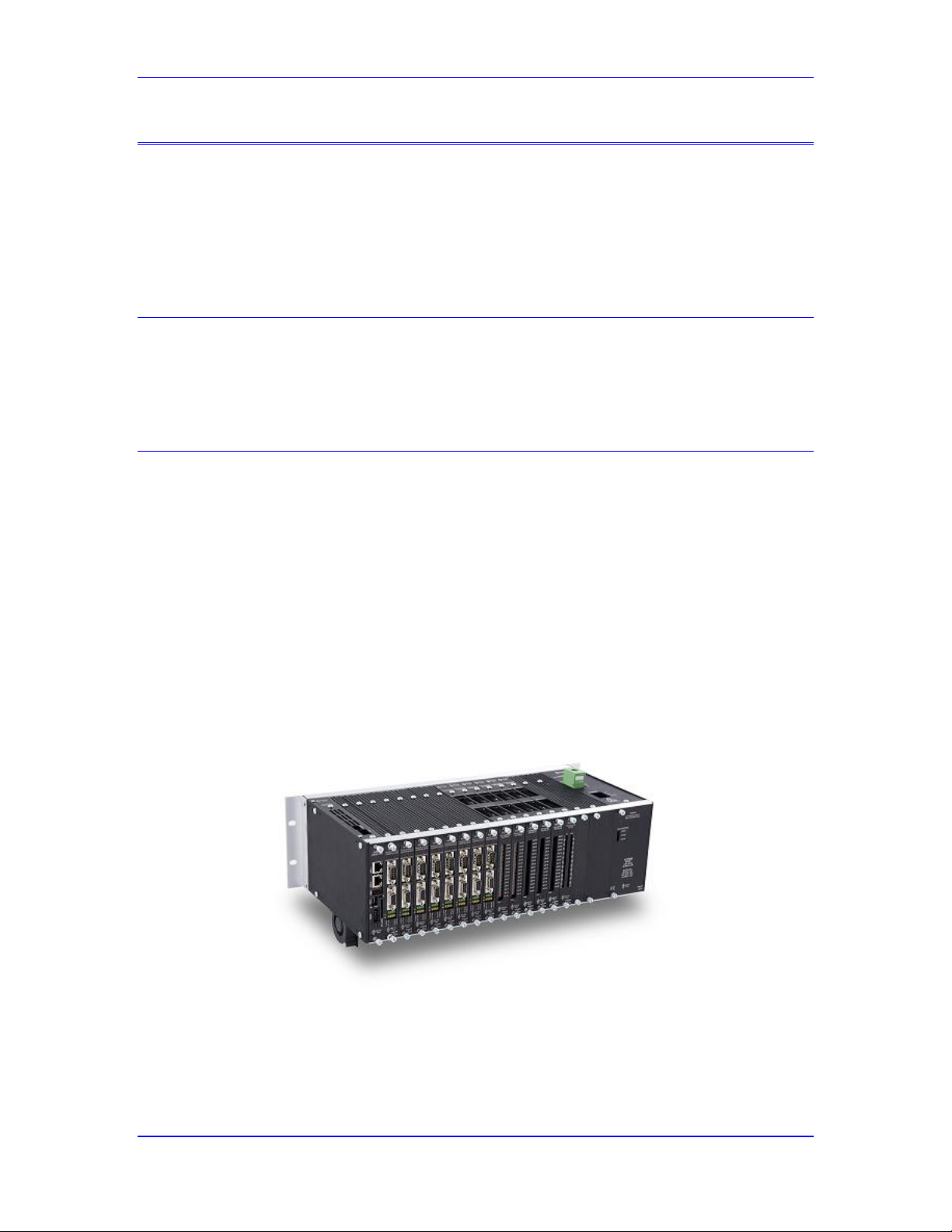
Power PMAC User’s Manual
Power PMAC Family Overview 26
POWER PMAC FAMILY OVERVIEW
The Power PMAC family of controllers is the latest generation of motion and machine controllers
from Delta Tau Data Systems, Inc. It is available in a large and increasing number of
configurations, permitting the user to configure controller hardware and software to particular
application needs. This chapter provides a brief overview of the Power PMAC structure; all items
mentioned here are covered in more detail elsewhere in the User’s Manual or in related reference
manuals.
What Is Power PMAC?
Power PMAC is a general-purpose embedded computer with a built-in motion and machinecontrol application. It also provides a wide variety of hardware machine interface circuitry that
permits connection to common servo and stepper drives, feedback sensors, and analog and digital
I/O points.
Power PMAC Configurations
Power PMAC is available in multiple physical configurations, optimized for different styles of
applications. Each configuration shares the same core software capabilities, but the hardware
interfaces differ between configurations.
Power UMAC
The Power UMAC is a modular rack-mounted configuration of the Power PMAC. It consists of a
set of 3U-format (100mm x 160mm) boards in a Euro-Card rack. Along with the required Power
PMAC CPU board, a customized set of interface boards can be added, communicating over a
common backplane. These include digital and analog servo interface boards, digital and analog
general-purpose I/O boards, machine network interface boards, and industrial fieldbus interface
boards. A power supply installed in the rack can be used, or an external supply.
Example Power UMAC Configuration
Because of its modular nature, the Power UMAC provides the most flexible configuration for
Power PMAC systems.
Page 27
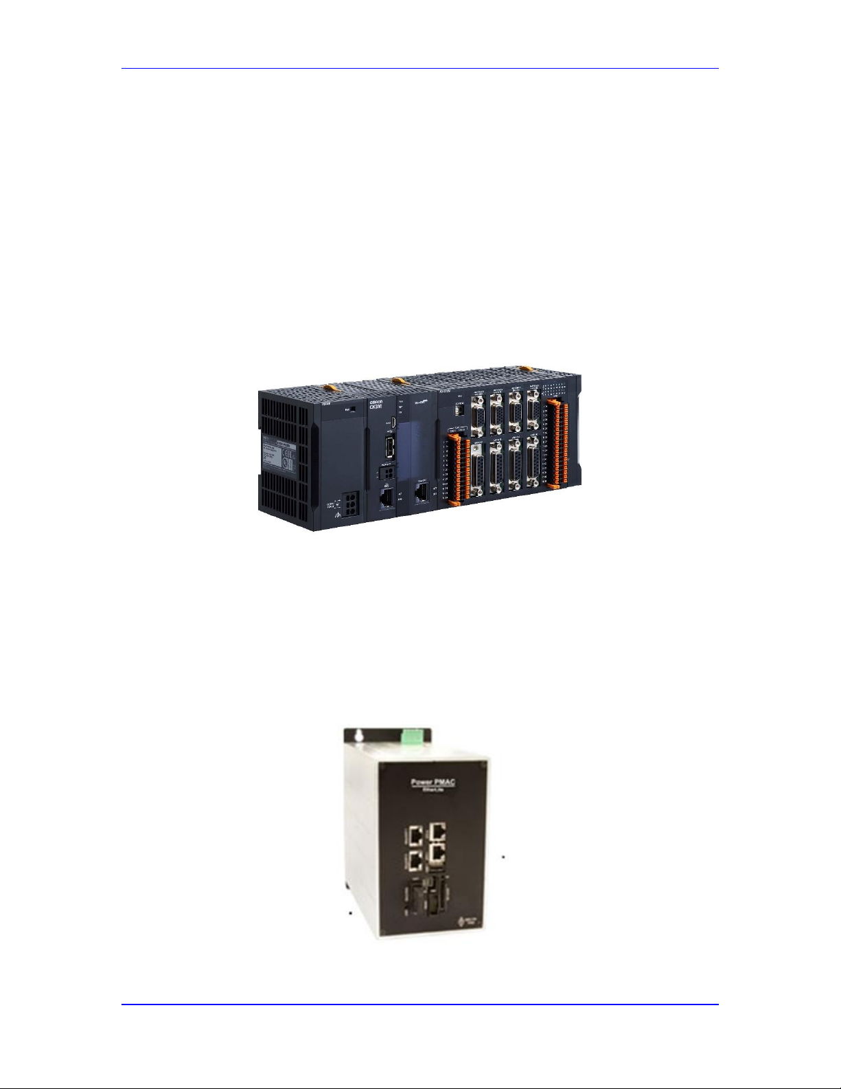
Power PMAC User’s Manual
Power PMAC Family Overview 27
Compact Power UMAC
The Power PMAC is also available in the “Compact Power UMAC” configuration. This is similar
to the standard Power UMAC, with 3U-format (100mm x 160mm) boards on a common
backplane. However, the field wiring is distributed behind the backplane, as in the Compact PCI
format (but there is no PCI interface). This requires a customized and engineered distribution
scheme, so this format is intended for high-volume OEMs who have the capability and financial
justification for such a distribution scheme.
CK3M (µUMAC)
The CK3M is a small modular rack-mounted configuration of the Power PMAC, with similar
form factor to the Omron NJ/NX PLCs. Along with the required Power PMAC CPU module, a
customized set of interface boards can be added, communicating over a common backplane
within one rack (line), and extensible to up to 4 lines through expansion modules and cables.
Example CK3M (µUMAC) Controller Configuration
Power PMAC Etherlite
The Power PMAC Etherlite is a compact and cost-effective configuration intended for control
through industrial networks and fieldbuses. It consists of a Power PMAC CPU board, a network
interface board that can be configured for the MACRO fiber optic network, the EtherCAT
electrical network, or both. Optionally, a fieldbus interface board for buses such as Profibus,
DeviceNet, or CCLink can be installed.
Power PMAC Etherlite Controller
Page 28
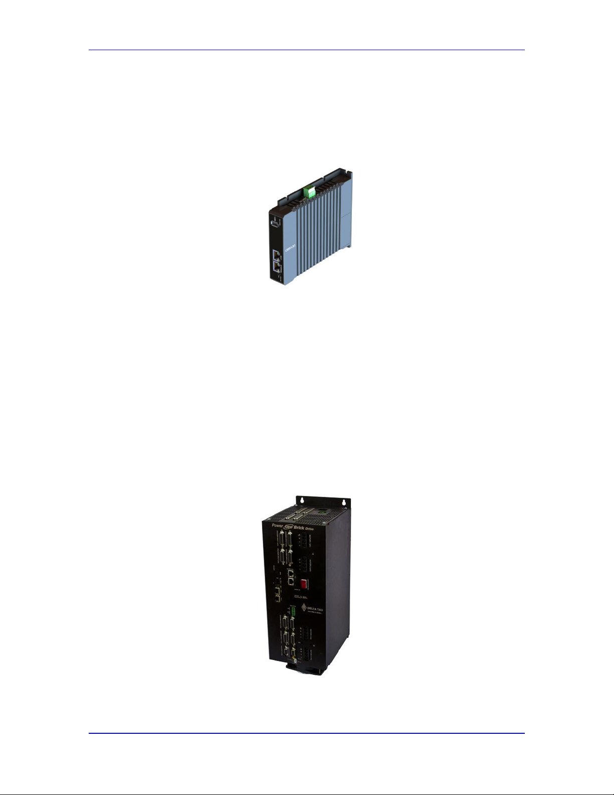
Power PMAC User’s Manual
Power PMAC Family Overview 28
The Power PMAC Etherlite is commonly used for large systems where networked connections
are important to simplify system wiring.
CK3E (µPowerPMAC)
The µPowerPMAC [CK3E] controller is a packaged single-board controller that interfaces to
servo drives and I/O devices through the EtherCAT network.
CK3E (µPowerPMAC) Controller
Power Brick Configurations
The Power Brick controllers are integrated “boxed” configurations of Power PMAC. The come in
three configurations: Power Brick AC, Power Brick LV, and Power Brick Controller.
All of these configurations can support multiple styles of position feedback: digital incremental
(quadrature) encoders, serial encoders, analog incremental (sinusoidal) encoders, and resolvers.
All configurations provide a standard set of “flags” (e.g. limit, home, and user) for each axis, with
a set of general-purpose digital I/O. General-purpose analog I/O is also available.
Power Brick AC
The Power Brick AC combines a Power PMAC controller with integrated 3-phase motor
amplifier circuits for 4, 6 or 8 axes. The AC power input for the amplifiers can be up to 240VAC.
Power Brick AC 4-Axis Configuration
Page 29
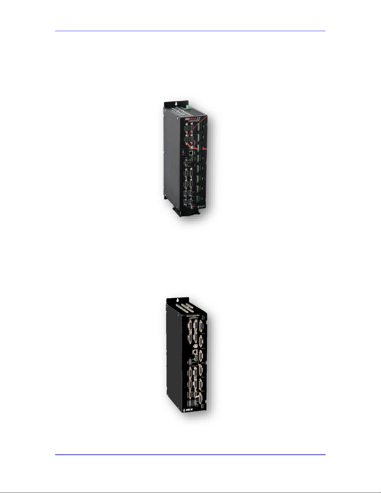
Power PMAC User’s Manual
Power PMAC Family Overview 29
Power Brick LV
The Power Brick LV combines a Power PMAC controller with integrated motor amplifier circuits
for 2-phase and 3-phase motors for 4 or 8 axes. It accepts a DC power input for the amplifiers of
up to 60VDC. Each axis can be configured by the user for 2-phase or 3-phase motors, open-loop
(stepper) or closed-loop (servo).
Power Brick LV 8-Axis Configuration
Power Brick Controller
The Power Brick Controller combines a Power PMAC controller with an integrated multi-axis
amplifier-interface board in a single boxed package. Both analog and digital amplifier interface
boards are available, and each can be provided in 4-axis and 8-axis configurations.
Power Brick Controller 4-Axis Configuration
Page 30
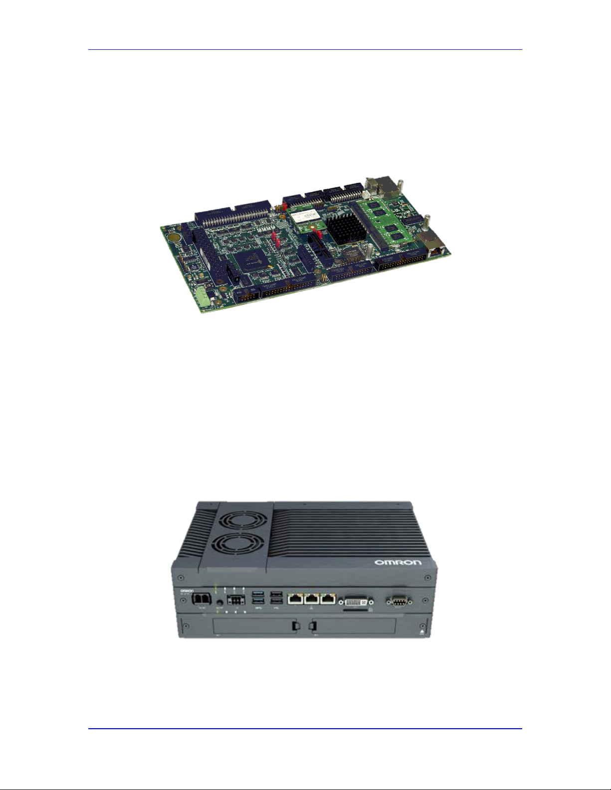
Power PMAC User’s Manual
Power PMAC Family Overview 30
Power Clipper
The Power Clipper is a compact and cost-effective configuration of the Power PMAC for
embedded applications. It combines the Power PMAC CPU, 4 channels of axis interface circuitry,
32 general-purpose digital I/O points, and 4 optional analog inputs onto a single small circuit
board. A second Clipper board, built without the CPU, provides another set of axis and generalpurpose I/O.
Power Clipper Controller Board (without fan assembly)
Power PMAC on Sysmac IPC
The Power PMAC software has also been configured to run on Omron’s Sysmac IPC (Industrial
Personal Computer). The Sysmac IPC is a multi-core PC, using one core for Power PMAC
interrupt-driven foreground tasks, and a second core for its background tasks, both running under
a real-time Linux operating system. Remaining cores are available for other uses such as HMI
and network interfaces, running under the Microsoft Windows operating system. The operation of
both operating systems is managed by an overall “hypervisor”.
The interface to the servo drives and I/O devices on these PC-based systems is done through the
EtherCAT network.
Omron Sysmac IPC
Page 31

Power PMAC User’s Manual
Power PMAC Family Overview 31
What Power PMAC Does
Power PMAC can handle all of the tasks required for machine control, constantly switching back
and forth between the different tasks thousands of times per second. The major tasks involved in
machine control are summarized here. More details on how these tasks are prioritized are given in
the chapter Power PMAC System Configuration.
Execute Sequenced Motion Programs
The most obvious task of Power PMAC is executing sequences of motions given to it in a motion
program written in the Power PMAC Script language. When told to execute a motion program,
Power PMAC works through the program one move at a time, performing all the calculations up
to that move command (including non-motion tasks) to prepare for actual execution of the move.
Power PMAC is always working ahead of the actual move in progress, so it can blend properly
into the upcoming move(s), if required. See the chapter Writing and Executing Script Programs
for more details.
Execute Asynchronous PLC Programs
The sequential nature of the motion program suits it well for commanding a series of moves and
other coordinated actions but these programs are not good at performing actions that are not
directly coordinated with the sequence of motions. For those types of tasks, Power PMAC
provides the capability for users to write “PLC programs”. These are named after Programmable
Logic Controllers because they operate in a similar manner, continually scanning through their
operations as processor time allows. These programs are very useful for any task that is
asynchronous to the motion sequences. PLC programs can be written both in the Power PMAC
Script language and in C. Both types of programs can execute either as interrupt-driven
foreground tasks, or as background tasks. See the chapters Writing and Executing Script
Programs and Writing C Functions and Programs for more details.
Perform Kinematic Transformations
Power PMAC can automatically perform user-specified transformations between “tool-tip” (axis)
coordinates in a geometry that the user finds easy to work with (e.g. a Cartesian reference frame)
and the underlying “joint/actuator” (motor) coordinates in which the machine is built. The
transformation can be a basic, mathematically linear, scaling and offset transformation, permitting
scaling and offsetting into user engineering units and a flexible programming origin for each axis.
This can be accomplished with simple “axis-definition” equations.
The transformation can also be a complex, mathematically non-linear, transformation
implemented in user-written “kinematic” subroutines. These subroutines can employ
sophisticated math and logic to perform the transformation, selecting if necessary between
multiple solutions, and even iterating to solutions when closed-form solutions are not available.
See the chapter Setting Up a Coordinate System for more details
Process Feedback and Master Position Data
Power PMAC can perform sophisticated processing of sampled position-related data to prepare it
for feedback or master use in servo-loop algorithms. This is done each servo cycle in a structure
called the “Encoder Conversion Table”. The ECT can combine several sampled values to provide
an enhanced net position value, as with timer-based extension of incremental encoders or
sinusoidal interpolation of analog encoders. It can filter noisy values, automatically eliminate
obviously erroneous values, integrate values, and combine multiple values by sum or difference.
Page 32

Power PMAC User’s Manual
Power PMAC Family Overview 32
See the chapters Setting Up Feedback and Master Position Sensors and Setting Up the Encoder
Conversion Table for details.
Compute Commanded Motor Trajectories
Each servo cycle, Power PMAC can compute a new commanded position for each active motor,
providing a “setpoint” for the servo loop to act upon. This commanded position can be from a
programmed axis move, a direct motor move such as a jogging or homing search move, a position
following (electronic gearing) algorithm, or some combination of the above. See the chapters
Executing Individual Motor Moves and Power PMAC Move Mode Trajectories for details.
Calculate Compensation Table Corrections
Each servo cycle, Power PMAC can calculate table-based corrections to key motor parameters.
Each table can be based on the position of 1, 2, or 3 motors (linear, planar, or volumetric tables,
respectively), and can compensate the position, torque, or backlash correction of one or more
motors. The “target” motor may or may not be the same as one of the “source” motors. These
tables can provide classic “leadscrew” compensation, and more sophisticated corrections,
including for cross-axis position compensations for straightness errors, and torque compensations
for motor cogging torque variations. See the chapter Setting Up Compensation Tables for details.
Calculate Cam Table Motions
Each servo cycle, Power PMAC can calculate table-based motion for a motor based on the
position of another motor, providing “electronic cam table” capability. In each “zone” of the
table, Power PMAC computes the cam position by 3rd-order interpolation between table points,
torque offset by 3rd-order interpolation between table points, and a discrete output word for the
zone. It is possible to have Power PMAC compute the optimal torque offsets for each zone itself
through “iterative learning control” to minimize the position errors over multiple cycles. See the
chapter Setting Up Electronic Cam Tables for details.
Close Motor Position/Velocity Servo Loops
Each servo cycle, Power PMAC can close the servo loop for all active motors. Using the
computed command position for the servo cycle, the processed actual position information, and
the user-set servo gain term values, it calculates the feedback and feedforward components of the
servo effort that is designed to minimize the difference between the commanded and actual
position values. See the chapter Setting Up the Servo Loop for details.
Perform Electronic Phase Commutation
If Power PMAC is configured to perform the commutation for a multiphase motor, it will
automatically perform commutation updates at a selectable fixed frequency (often around 9 kHz).
The commutation, or phasing, update for a motor consists of measuring and/or estimating the
rotor magnetic field orientation, then apportioning the command that was calculated by the servo
update among the different phases of the motor. Once configured, this task occurs automatically
without the need for any explicit commands. See the chapter Setting Up Power PMAC-Based
Commutation and/or Current Loop for more details.
Close Motor Current Loops
If Power PMAC is configured to perform digital current-loop closure for a motor (as part of the
commutation algorithm), each commutation update it will automatically read the motor phase
current values from analog-to-digital converter registers, compare these values to the commanded
current values, and compute the phase voltage command levels necessary to obtain the command
Page 33

Power PMAC User’s Manual
Power PMAC Family Overview 33
current levels. These phase voltage commands are usually encoded as PWM duty cycles, with the
PWM signals directly driving the amplifier power transistors. See the chapter Setting Up Power
PMAC-Based Commutation and/or Current Loop for more details.
Provide Synchronous Data Gathering
Every servo cycle (or every “n” servo cycles), Power PMAC can automatically log the values of
up to 128 user-specified hardware and/or software registers into a data buffer for later analysis.
Power PMAC’s Integrated Development Environment (IDE) software for the PC can
automatically upload the gathered data and plot it in a variety of user-configurable formats. This
functionality is also used for interactive and automatic tuning algorithms. It is also possible to
gather the contents of up to 16 user-specified registers every phase cycle; this functionality is
mainly used for setting up commutation and tuning the digital current loop.
Perform General Housekeeping and Safety Checks
Power PMAC is continually and automatically monitoring its hardware and software functions,
updating status information and performing key safety checks for all active motors and coordinate
systems. The safety checks include hardware and software overtravel position limits, position
following error, amplifier fault signals, integrated current limits, encoder loss detection, and a
watchdog timer check. See the chapter Making Your Power PMAC Application Safe for details.
Respond to Host Computer Commands
Power PMAC is continually checking for commands over its Ethernet port. As a networked
device, commands can come from multiple tasks within a single computer, and from multiple
computers. These commands can be for an action, as in jogging a motor or starting a program, or
can be to query a value or state in the controller. See the chapter Talking to Power PMAC for
details.
Execute Independent C Applications
Power PMAC can execute independent applications written in C under the general-purpose
operating system (GPOS). These applications have access to Power PMAC’s shared memory and
I/O, but do not need to use these structures. See the chapter Writing C Functions and Programs in
Power PMAC for details.
Page 34
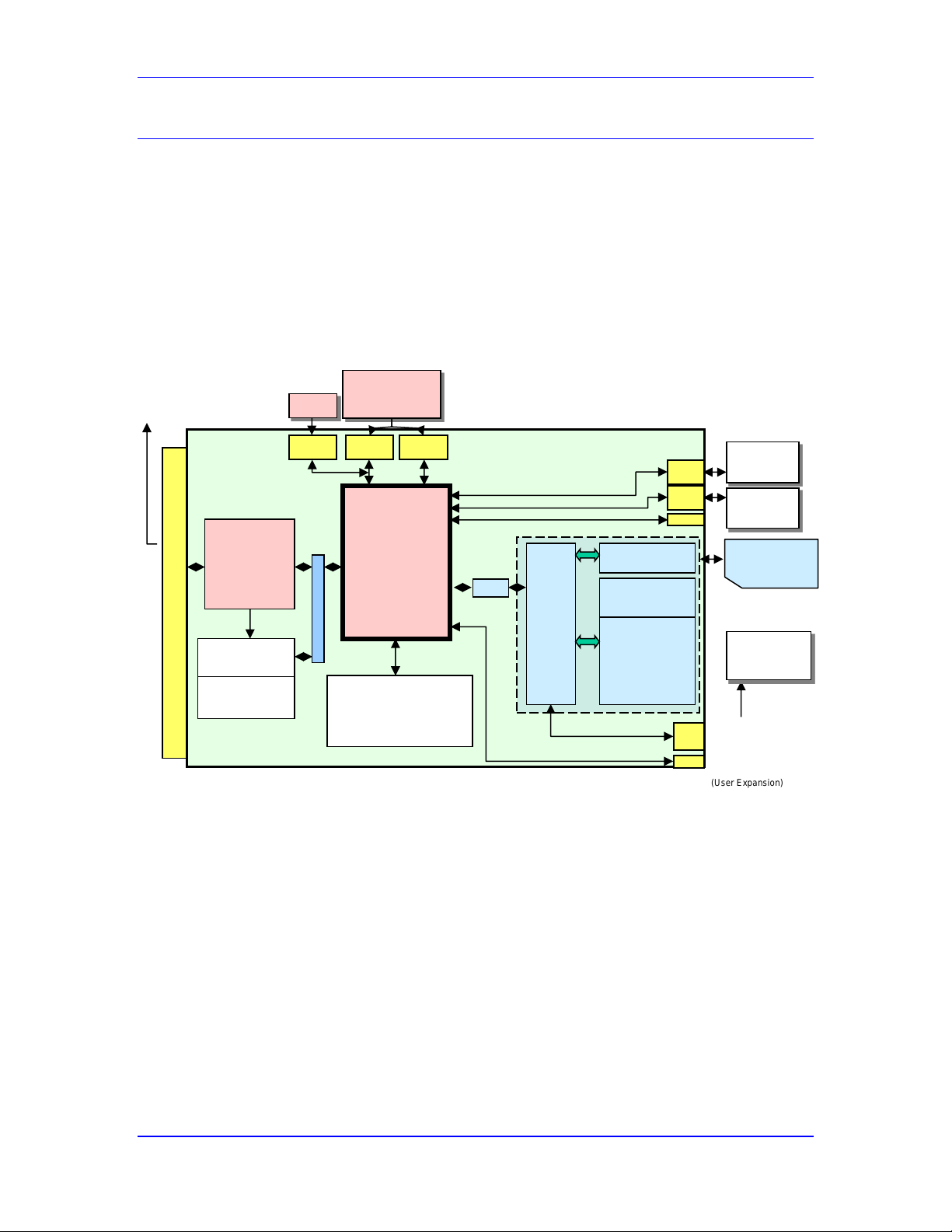
Power PMAC User’s Manual
Power PMAC Family Overview 34
Key Hardware Components
Power PMAC hardware consists primarily of the CPU and machine interface circuitry. This
section summarizes these key hardware components. Note that the Soft Power PMAC, running on
an industrial PC (IPC) as the “Motion Machine”, does not have the interface hardware. Instead, it
uses an Ethernet-based network to communicate with the machine.
CPU Section
The core of the Power PMAC is the central processing unit (CPU), consisting of a
microprocessor, active memory, and non-volatile memory. The following figure shows the block
diagram of the Power PMAC CPU for the UMAC rack-mounted controller. Other configurations
are similar.
Power PMAC CPU Section Block Diagram
Processor
Initial hardware implementations of the Power PMAC use an embedded Power PC RISC
microprocessor. This 32-bit processor has relatively low heat dissipation requiring only limited
cooling, and it has a substantial number of peripherals built in, keeping the parts count of the
CPU section small. The processor has a dedicated hardware floating-point math engine, capable
of processing mathematical operations directly on both single-precision (32-bit) and doubleprecision (64-bit) floating-point values.
Power PMAC
CPU
800Mhz - 1.0Ghz
DDR2
1GB or 2GB
RAM w/ ECC
Removable SOCDIMM
16M Motion Prog Buffer (adjustable)
8M PPmac Memory Map (Fixed)
1M User Shared Memory (adjustable)
AMD
NOR Boot Flash
64MB
Contains everything
necessary to boot
Linux RTOS Kernel
Lattice CPLD
UBUS I/F
*Can be used as
SATA or PCIe (x1)
USB
Hub/Card
Reader
SD/MMC Expansion Slot
(User Expansion)
Soldered Down NAND
Flash 2 or 8GB
Contains Complete
Operating System
Files
plus Add on products
ie. IEC1131, EPICS
NC Application,
Ethercat, etc ...
User Interface Software
USB 2.0 Host
Expansion Port
(User Expansion)
USB 2.0 Device
1G Eth
1G Eth
RS232
USB 2.0
PCIe (x1)
PCIe (x4)
SATA
Disk
Drive
Ethercat,
Powerlink,
Modbus, etc…
PC Comm
i.e. -Web,
TCP Sockets
Up to 32GB SDHC
Memory Card (User
Programs)
UBUS
Keyboard,
Mouse, RS232,
Hard Drive,
Memory Stick etc.
RS232
Ethernet
Ethernet
USB
USB
Video Card
Vision System Card
Fieldbus Cards,
etc...
Page 35

Power PMAC User’s Manual
Power PMAC Family Overview 35
Subsequent hardware implementations use embedded microprocessors with the ARM
architecture. These also have low heat dissipation requiring minimal cooling.
Single-core processors running at 800 MHz and 1.0 GHz are available. Dual-core processors
running at 1.2 GHz are available.
When Power PMAC software runs on a PC, such as Omron’s IPC, the processor is of the x86
architecture.
Active Memory (RAM)
The active memory in Power PMAC is DDR2 or 3 class RAM, typically with a capacity of 1 – 2
gigabytes (GB). The Power PMACs with Power PC processors use error-correcting memory
modules. The more cost-effective ARM processors use standard memory modules without error
correction
Non-Volatile Memory (Flash)
The non-volatile memory provided with Power PMAC is solid-state flash memory. The computer
BIOS for boot loading is stored in NOR flash. The operating system, PMAC application software
and user projects are stored in NAND flash and loaded into RAM automatically on power-up and
reboot/reset. The built-in NAND flash is typically provided with a capacity of 1 – 4 GB.
Users can provide additional NAND flash capacity through USB-stick and/or SD card modules,
depending on the configuration of the Power PMAC.
Machine Interface ICs
The processor interfaces to the machine through a variety of “machine interface” ICs. These
appear to the processor as a set of memory-mapped registers and provide a variety of input and
output signals to machine devices. Different ICs provide various interfaces, both for motion
control and for general-purpose analog and digital I/O.
PMAC2-Style “DSPGATE1” Servo IC
The PMAC2-style Servo IC is called the “DSPGATE1”. It is a 4-channel part with 64 memory-
mapped registers. Each channel supports the following features:
3 output command signal sets, configurable as either:
o 2 serial data streams to digital-to-analog converters of up to 18 bits, and one
pulse-and-direction pair, or
o 3 pulse-width-modulated (PWM) top and bottom pairs
Input for digital quadrature with index, pulse-and-direction, or MLDT feedback
4 input flags (home, +/-limit, user) that can trigger hardware encoder capture
Amplifier-fault input
4 supplemental input flags (T, U, V, W) for hall commutation sensors, sub-count data,
fault codes, or general use
Amplifier-enable output
Hardware position-compare output
Input from 2 analog-to-digital converters of up to 18 bits (from amplifier or accessory
board)
The DSPGATE1 IC also has on-board software-configurable clock generation circuitry. It can
generate the “servo” and “phase” clocks for the entire Power PMAC system (only one IC will do
Page 36
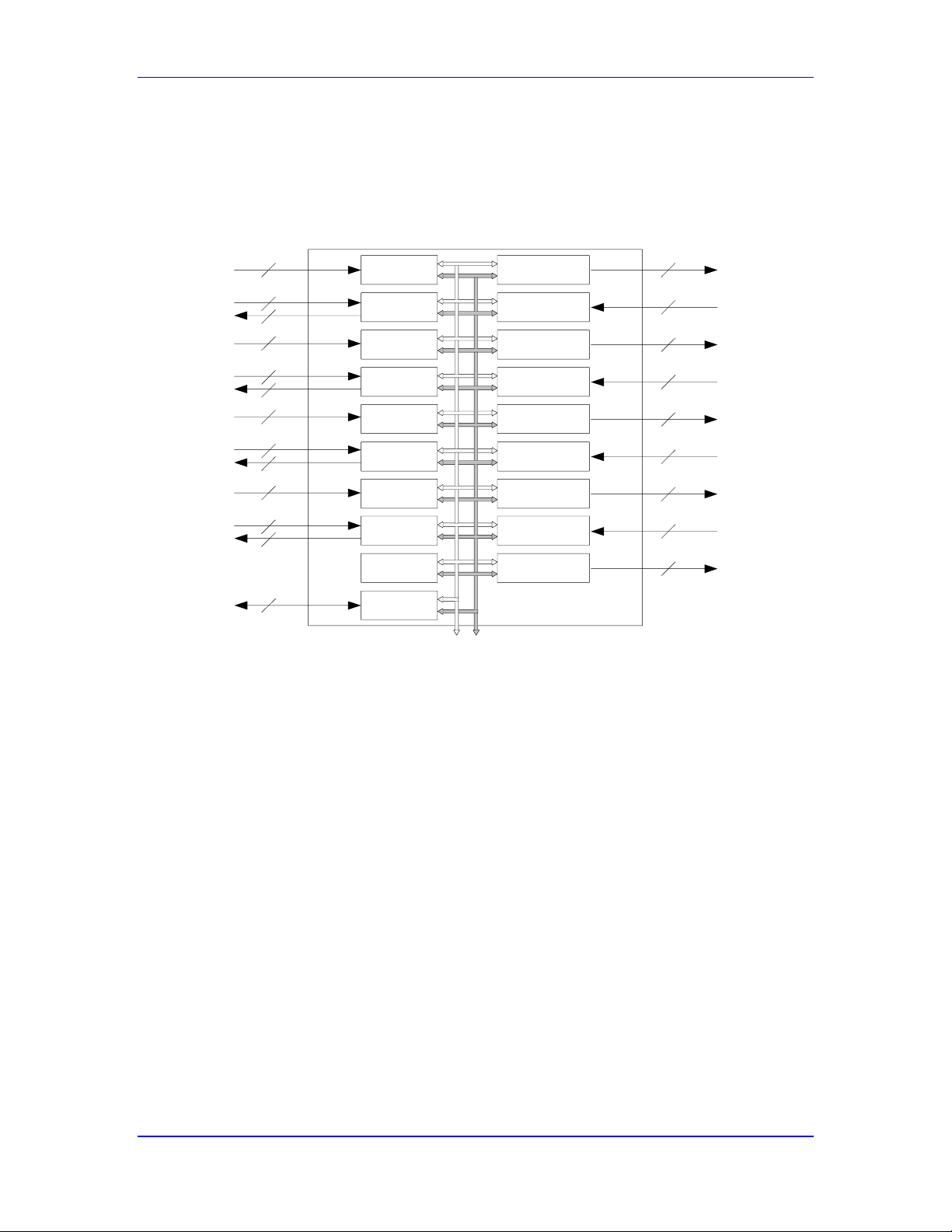
Power PMAC User’s Manual
Power PMAC Family Overview 36
this; the others will accept these as inputs). It also generates the clock signals that drive its own
circuitry: encoders, DACs, ADCs, PWM and PFM (pulse-frequency-modulation).
Clock, PLL
Encoder/Flag
Status & Control
Flag 4
Encoder 4
Flag 3
Encoder 3
Flag 2
Encoder 2
Flag 1
Encoder 1 Output1 A,B,C
ADCIN1 A,B
Output2 A,B,C
ADCIN2 A,B
Output3 A,B,C
ADCIN3 A,B
Output4 A,B,C
ADCIN4 A,B
Output/ADCIN
Control
24-bit
DATA BUS
6-bit
ADDRESS BUS
6
2
6
2
6
2
6
2
2
3
9
2
3
9
2
3
9
2
3
9
2
PMAC2 Gate Array IC
“DSPGATE1”
2
PMAC2-Style “DSPGATE1” Servo IC
The DSPGATE1 IC is presently provided on the following Power PMAC products:
ACC-24E2 UMAC PWM Axis-Interface Board
ACC-24E2A UMAC Analog Axis-Interface Board
ACC-24E2S UMAC Stepper Axis-Interface Board
ACC-51E UMAC Sine-Encoder Interpolator Board
ACC-58E UMAC Resolver Converter Board
ACC-24C2A Compact UMAC Analog Axis-Interface Board
ACC-51C UMAC Compact Sine-Encoder Interpolator Board
PMAC2-Style “DSPGATE2” MACRO IC
The PMAC2-style “DSPGATE2” MACRO IC provides a 16-node bi-directional interface for the
MACRO ring. Of these nodes, eight can be used as “servo nodes”, each of which can transfer all
Page 37

Power PMAC User’s Manual
Power PMAC Family Overview 37
of the command and feedback data required for the servo and commutation of a motor. Six of the
nodes can be used for general-purpose I/O, each node supporting 72 bits of hard real-time I/O in
each direction. Two of the nodes are for non-real-time communications, including “broadcast”
mode in which a master controller can talk to all of its slave devices simultaneously.
The DSPGATE2 IC also has on-board software-configurable clock generation circuitry. It can
generate the “servo” and “phase” clocks for the entire Power PMAC system (only one IC will do
this; the others will accept these as inputs).
The DSPGATE2 IC is presently provided on the ACC-5E UMAC MACRO-Interface Board.
PMAC2-Style “IOGATE” Digital I/O IC
The PMAC2-style IOGATE IC is used to access general-purpose digital I/O on most of the
UMAC I/O boards. It provides 48 I/O points, addressed as 6 bytes in consecutive registers.
Different boards use different buffers and drivers around the IOGATE to provide the specific I/O
features desired. While on the IOGATE itself, each I/O point is individually selectable as to
direction, on most of the I/O boards, each point’s direction is fixed by the external circuitry for
that point. The IOGATE must be set up at power-on/reset to support the particular direction
configuration of the board it is used on.
The IOGATE IC is presently provided on the following Power PMAC products:
ACC-11E UMAC 24V 24-Point Sinking/Sourcing Output, 24-Point Sinking/Sourcing
Input Board
ACC-14E UMAC 5V 48-Point I/O Board
ACC-65E UMAC Protected 24V 24-Point Sourcing Output, 24-Point Sinking/Sourcing
Input Board
ACC-66E UMAC Protected 24V 48-Point Sinking/Sourcing Input Board
ACC-67E UMAC Protected 24V 48-Point Sourcing Output Board
ACC-68E UMAC Protected 24V 24-Point Sinking Output, 24-Point Sinking/Sourcing
Input Board
ACC-11C Compact UMAC 24V 24-Point Sinking/Sourcing Output, 24-Point
Sinking/Sourcing Input Board
Page 38
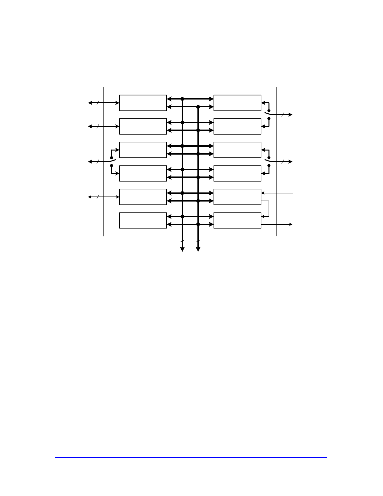
Power PMAC User’s Manual
Power PMAC Family Overview 38
PMAC3-Style “DSPGATE3” Machine Interface IC
The PMAC3-style “DSPGATE3” machine interface IC provides servo, MACRO, and I/O
interfaces in a single IC. In different products, different parts of this interface are used. It appears
to the processor as 512 memory-mapped 32-bit registers.
Servo Channel 1
(Chan[0])
Servo Channel 3
(Chan[2])
I/O Bank 1
(Gpio[0])
Servo Channel 2
(Chan[1])
I/O Bank 2
(Gpio[1])
Clock Control
Configuration
Control
I/O Bank 3
(Gpio[2])
Servo Channel 4
(Chan[3])
I/O Bank 4
(Gpio[3])
MACRO A Nodes
MACRO B Nodes
32
32
32
32
32
32
9
Data
Bus
Address
Bus
2
From
MACRO
Ring
To
MACRO
Ring
DSPGATE3 Machine Interface IC Block Diagram
It provides 4 servo channels, with each servo channel supporting the following features:
4 output command signal sets, configurable as either:
o 3 serial data streams to digital-to-analog converters of up to 24 bits, and one
pulse-and-direction pair, or
o 4 pulse-width-modulated (PWM) top and bottom pairs
Input for digital quadrature with index, pulse-and-direction, or MLDT feedback
Hardware “1/T” timer-based sub-count interpolation
4 input flags (home, +/-limit, user) that can trigger hardware encoder capture
Amplifier-fault input
4 supplemental input flags (T, U, V, W) for hall commutation sensors, sub-count data,
fault codes, or general use
Amplifier-enable output
3 additional output flags
Hardware position-compare output
Input from 8 analog-to-digital converters of up to 18 bits (from amplifier or accessory
board)
Hardware 16-bit arctangent interpolation from “sine” and “cosine” ADCs for sine
encoder and resolver conversion
Page 39

Power PMAC User’s Manual
Power PMAC Family Overview 39
The DSPGATE3 IC also provides 4 banks of 32 general-purpose digital I/O points, with each I/O
point individually selectable for direction and software polarity. The first bank has dedicated pins
on the IC; the second, third, and fourth banks share pins with the second, third, and fourth servo
channels, respectively, with each pin individually selectable with regard to function.
In addition, it provides a 32-node bi-directional interface for the MACRO ring. Of these nodes,
16 can be used as “servo nodes”, each of which can transfer all of the command and feedback
data required for the servo and commutation of a motor. 12 of the nodes can be used for generalpurpose I/O, each node supporting 72 bits of hard real-time I/O in each direction. Four of the
nodes are for non-real-time communications, including “broadcast” mode in which a master
controller can talk to all of its slave devices simultaneously.
Finally, it has on-board software-configurable clock generation circuitry. It can generate the
“servo” and “phase” clocks for the entire Power PMAC system (only one IC will do this; the
others will accept these as inputs).
The DSPGATE3 IC is presently provided on the following Power PMAC products:
ACC-24E3 UMAC Axis-Interface Board
ACC-5E3 UMAC MACRO-Interface Board
ACC-5EP3 Etherlite MACRO/EtherCAT-Interface Board
ACC-59E3 UMAC ADC/DAC Board
Power Brick Control Board
Power Clipper Controller Board
ACC-24S3 Clipper Axis Expansion Board
CK3W Axis Board for µUMAC (CK3M)
Page 40

Power PMAC User’s Manual
Talking to Power PMAC 40
TALKING TO POWER PMAC
During applications development, and often during applications execution, one or more “host”
computers will communicate with Power PMAC. This section covers the basic aspects of
communicating with Power PMAC from a host computer.
Communications Security
Communication with Power PMAC is intended to be done within a secure communications
environment. Any cybersecurity measures must be taken on the devices and networks that are in
communication with the Power PMAC.
OMRON SHALL NOT BE RESPONSIBLE AND/OR LIABLE FOR ANY LOSS, DAMAGE, OR
EXPENSES DIRECTLY OR INDIRECTLY RESULTING FROM THE INFECTION OF OMRON
PRODUCTS, ANY SOFTWARE INSTALLED THEREON OR ANY COMPUTER EQUIPMENT,
COMPUTER PROGRAMS, NETWORKS, DATABASES OR OTHER PROPRIETARY MATERIAL
CONNECTED THERETO BY DISTRIBUTED DENIAL OF SERVICE ATTACK, COMPUTER
VIRUSES, OTHER TECHNOLOGICALLY HARMFUL MATERIAL AND/OR UNAUTHORIZED
ACCESS.
It shall be the users sole responsibility to determine and use adequate measures and
checkpoints to satisfy the users particular requirements for (i) antivirus protection, (ii) data
input and output, (iii) maintaining a means for reconstruction of lost data, (iv) preventing
Omron Products and/or software installed thereon from being infected with computer
viruses and (v) protecting Omron Products from unauthorized access.
Physical Interface
Power PMAC utilizes an Ethernet interface for its main communications channel. Its Ethernet
ports are capable of 1 gigabit-per-second (1Gbps, 1000-Base-T) communications, but can also
communicate at lower speeds (e.g. 100Mbps, 100-Base-T), if that is all that the network or the
linked computer is capable of.
Power PMAC’s “ETH0” port is reserved for communications with the host computer(s)/network.
(Its “ETH1” port is reserved for Ethernet-based “fieldbus” communications that are not the
subject of this chapter.) It accepts a standard Ethernet cable with an RJ-45 jack. The connection
can be direct to the host computer or through a network, including through hubs and routers.
Use of the Internet Protocol Suite
Power PMAC communications utilizes standards from the “Internet Protocol Suite”, even when
the communications does not actually utilize the Internet. These standards are widely used around
the world, and Power PMAC’s employment of these standard protocols facilitates familiarity and
ease of use in applications.
Layers of the Internet Protocol Suite
The Internet Protocol Suite is a set of communications protocols for the Internet and similar
networks. It consists of four “encapsulated” abstraction layers, each with a variety of possible
protocols for different applications.
Page 41

Power PMAC User’s Manual
Talking to Power PMAC 41
Link Layer
The “link layer” is the lowest of these abstraction layers, operating just above the physical layer.
It handles specific networking requirements on the local link. Common link layer protocols
include ARP (Address Resolution Protocol), NDP (Neighbor Discovery Protocol), and MAC
(Media Access Control – for Ethernet, DSL, and FDDI).
Power PMAC employs the MAC link-layer protocol on its Ethernet interface. Each Power PMAC
has a unique MAC address for its Ethernet interface that makes it identifiable at any physical
location. This MAC address is not changeable by the user.
Internet Layer
The “internet layer” provides for basic datagram transmission between (potentially) different, and
different types, of networks (hence, “internetworking”, or “Internet”). The common protocols for
this layer have been Version 4 of the Internet Protocol (IPv4), Version 6 of the Internet Protocol
(IPv6), and Internet Control Message Protocol (ICMP).
Power PMAC employs Internet Protocol Version 6 (IPv6). Each Power PMAC has an IP address.
This is set at the factory to the default IP address of 192.168.0.200. The user can change this
address. (See Changing the Power PMAC IP Address, below.) If there are multiple Power
PMACs on the same network, each must have a unique address.
Transport Layer
The “transport layer” establishes data channels between host ports, providing end-to-end
communications services for applications. Common transport-layer protocols include UDP (User
Datagram Protocol), TCP (Transmission Control Protocol), RDP (Reliable Datagram Protocol),
and DCCP (Datagram Congestion Control Protocol).
Power PMAC employs the most common on these protocols, TCP. The use of TCP permits
communications with Power PMAC over indirect links, across networks, and even between
networks. Data packets can arrive out of order and be properly re-ordered by the recipient, and
packets with errors can be detected and retransmitted.
Application Layer
The “application layer” implements process-to-process communications across networks.
Different types of applications (“processes”) use different protocols at this layer. Telnet
implements “open text” (unsecured) communications by a virtual terminal. SSH (Secure Shell)
implements protected communications by a virtual terminal. FTP (File Transfer Protocol)
implements the movement of entire files across the network. DHCP (Dynamic Host
Configuration Protocol) permits the automatic assignment of IP addresses at execution time. POP
(Post Office Protocol) and SMTP (Simple Mail Transfer Protocol) are commonly used for e-mail
transmission.
Power PMAC employs several of these application-layer protocols. Basic command/response
communications is done through Telnet or SSH (“Secure Shell”) protocols. The Integrated
Development Environment (IDE) software for Windows PCs provided by Delta Tau uses SSH by
default for these functions, such as its “terminal window”, but this can be changed to Telnet by
the user. Most users prefer the added security of SSH, but some will choose the speed and
simplicity of Telnet.
Page 42
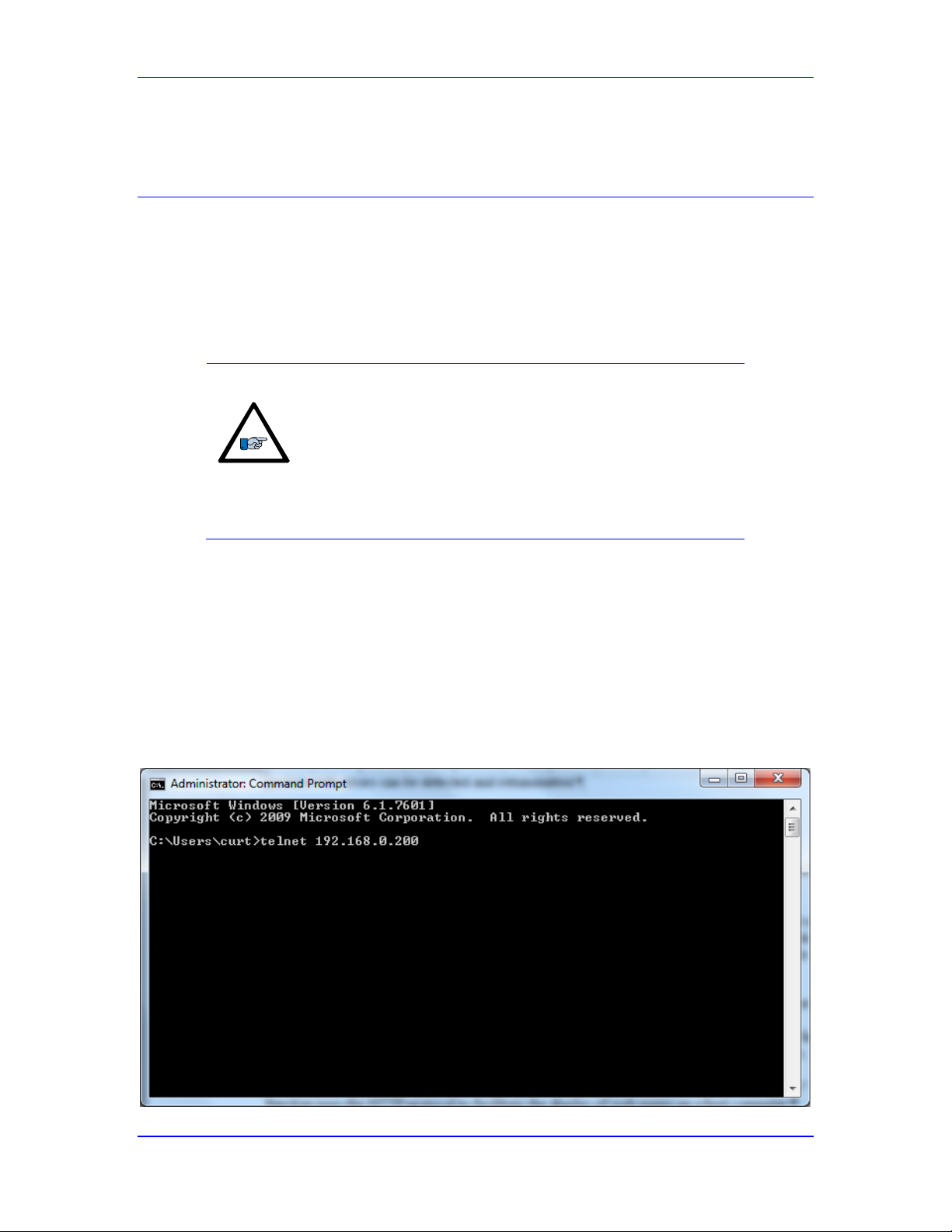
Power PMAC User’s Manual
Talking to Power PMAC 42
Power PMAC uses the FTP protocol for transfers of files to and from the Power PMAC,
including the applications project files, and gathered-data files.
Low-Level Terminal Communications
No matter how fancy the host communications software that implements command/response
communications with the Power PMAC, the underlying communications can be viewed as
occurring from a “terminal-emulator” window. For this reason, it is instructive for a new user to
implement communications with the Power PMAC through a simple software package that
implements such a terminal window. Typing commands and viewing responses permit the user to
understand how this command/response action works. This will aid the user in writing his own
software to automate the communications process.
Note
It is not required for any user to execute the examples shown in
this section. Most users will want first to establish
communications using the IDE software. However, reading
these examples and attempting to duplicate them can help the
user to understand how the communications works, especially
useful for those starting to write their own communications
software.
Terminal Emulator Programs
There are many terminal emulator programs available for Windows, Apple, Linux, and Unix
computers. The examples shown here use the Windows “Command Prompt” terminal emulator
(CMD.EXE) provided automatically with Microsoft Windows operating systems, but other
programs may be used as well.
Establishing First Communications
The first step is to tell the program to establish communications with the Power PMAC at its IP
address. In Windows Command Prompt, this is done by typing “telnet” followed by the IP
address, as shown in the following screen capture using the default IP address:
Page 43
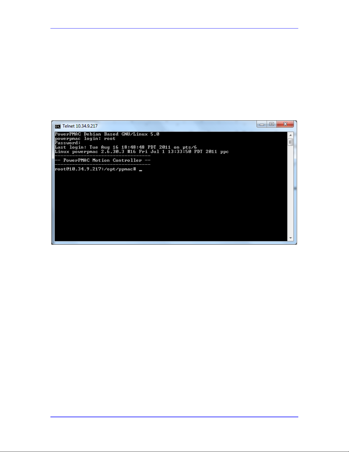
Power PMAC User’s Manual
Talking to Power PMAC 43
Establishing Communications from a Terminal Emulator
If the program does find the Power PMAC, it will display the response from the Power PMAC.
The first line of this response identifies the Power PMAC. The second line requests a user login.
At the login prompt, type “root” and hit Enter to request communications at the root
(administrator) level.
Next, Power PMAC will request the password. At this prompt, type “deltatau” and hit Enter.
This will provide the program with access to fundamental communications with the Power
PMAC computer. The following screen capture shows the communications so far:
Logging Into the Power PMAC Computer
At this point, you are talking to the computer operating system (Linux), not the control
application within the computer. You can use standard Linux commands to perform various tasks
on the computer.
Communicating with the Power PMAC Control Application
Once you have established communications with the Linux computer, you can communicate with
the Power PMAC control application within the computer by starting the basic communications
application gpascii. This application is in the opt/ppmac directory, so with the Linux
prompt (#) at this directory (which it will be as you first establish communications), type
“gpascii” and hit Enter.
The following screen capture shows the Linux “dir” (directory) command given at the
opt/ppmac prompt, showing that the gpascii communications application is present in that
directory, followed by the command to execute the gpascii application. The Power PMAC
response (shown) is “STDIN Open for ASCII Input”
Page 44
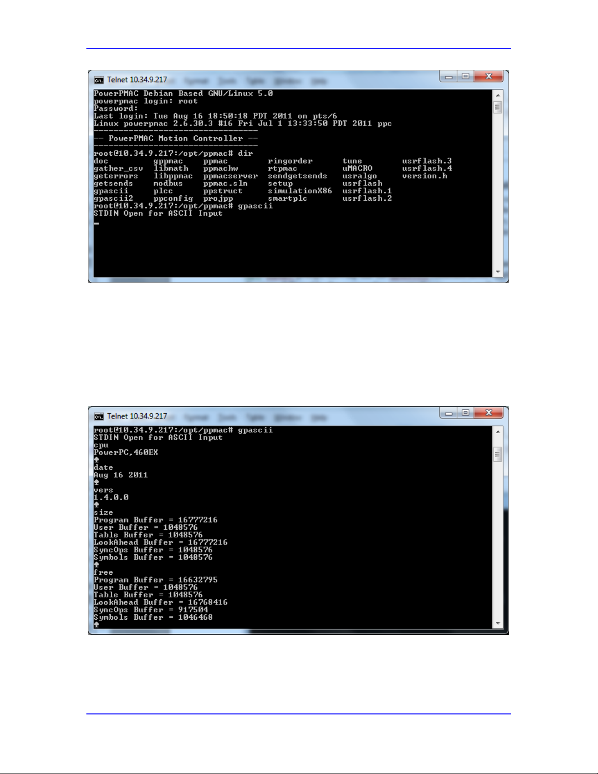
Power PMAC User’s Manual
Talking to Power PMAC 44
Starting Communications with the Power PMAC Control Application
At this point, you are talking to the Power PMAC control application within the computer, and
you can issue Power PMAC commands and view the responses. You might start by issuing
several query commands to find out basic information about the Power PMAC. The following
screen shot shows the response to the Power PMAC commands cpu, date, vers, size, and
free. The “spade” figure at the end of each Power PMAC response is the ACK (acknowledge)
character (ASCII value 07), which Power PMAC uses as its “end of transmission” character.
Basic Commands and Responses with the Power PMAC Control Application
Page 45

Power PMAC User’s Manual
Talking to Power PMAC 45
Establishing Communications with the IDE
Delta Tau’s Integrated Development Environment (IDE) software package for PCs running
Windows XP, Vista, 7, and 8 will be utilized by virtually all Power PMAC users to develop their
application. It hides a lot of the lower-level details of the communications seen in the examples
above from the user.
Startup Communications Control Window
When you start the IDE, you will be presented with the control window shown below. It allows
you to specify the address and protocol details for communication with your Power PMAC. The
IP address shown in the control must match that of your Power PMAC. You can enter a new IP
address in this control if the address shown here does not match that of your Power PMAC. Note
that the address you enter here simply specifies the IP address at which the IDE will attempt to
communicate; it does not set or change the IP address of the Power PMAC.
Most users will retain the default SSH underlying communications protocol, which automatically
selects virtual port number 22. Similarly, most users will select the default “Apply All Controls”
setting of “True”, which is the most convenient setting in the vast majority of cases where there is
only one Power PMAC in the system.
If you leave “Select Device at Startup” at its default setting of “True”, you will be presented with
this control window every time you start the IDE. If you set this to “False”, the IDE will
automatically try to establish communications at startup using the last settings you have made.
Click on “Connect” to attempt to establish communications with the Power PMAC at the
specified IP address. If the IDE is successful in establishing communications with the Power
PMAC computer, it will execute the gpascii application so it can communicate with the Power
PMAC control application.
Page 46
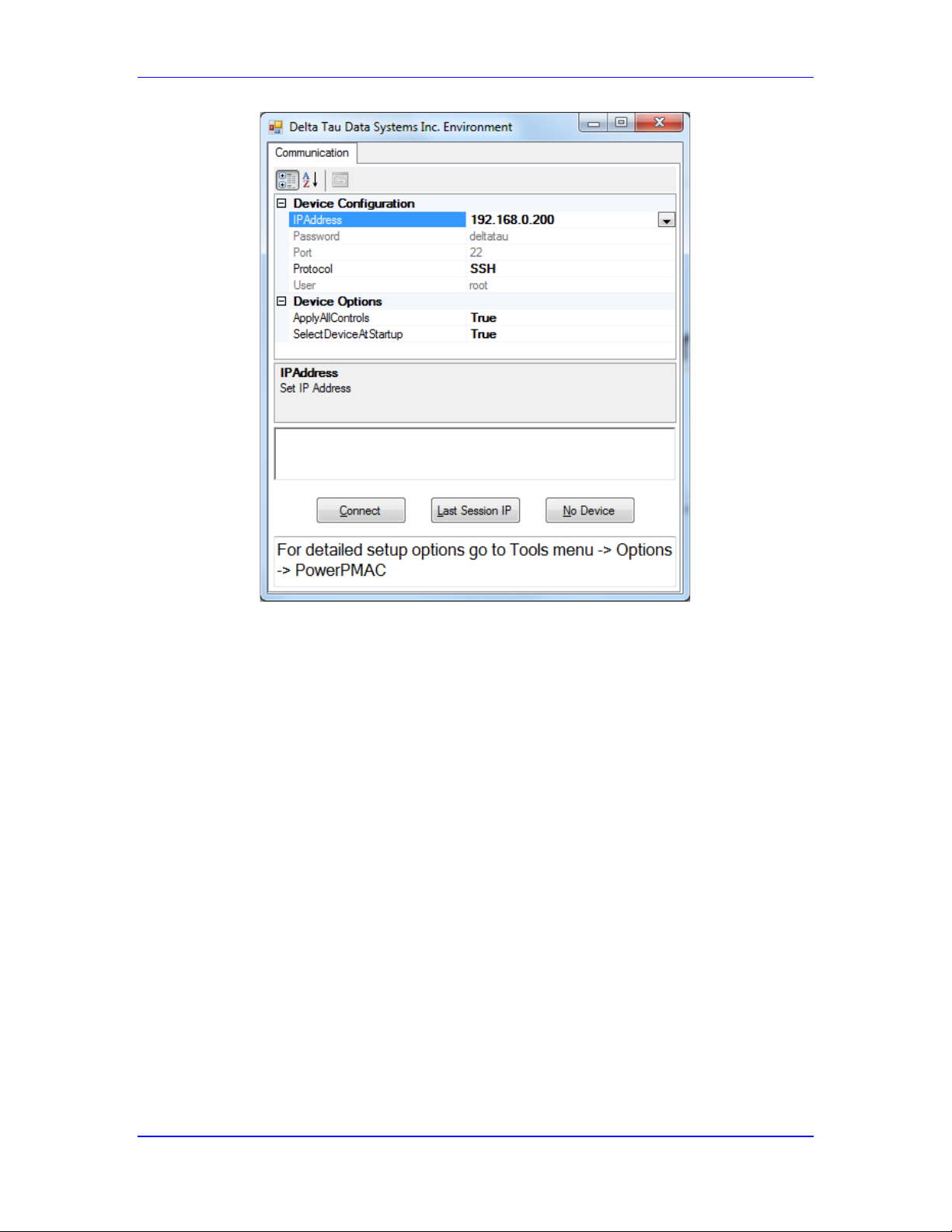
Power PMAC User’s Manual
Talking to Power PMAC 46
IDE Startup Control Window for Establishing Communications
Embedded Communications Control Window
If you want to view or change these settings after the start of execution of the IDE, select “Tools”
on the top menu bar, then “Options” from the pull-down menu. When the Options control
window appears, select Power PMAC. This will give you access to the same configuration
choices as the start up control window, as shown below.
Page 47
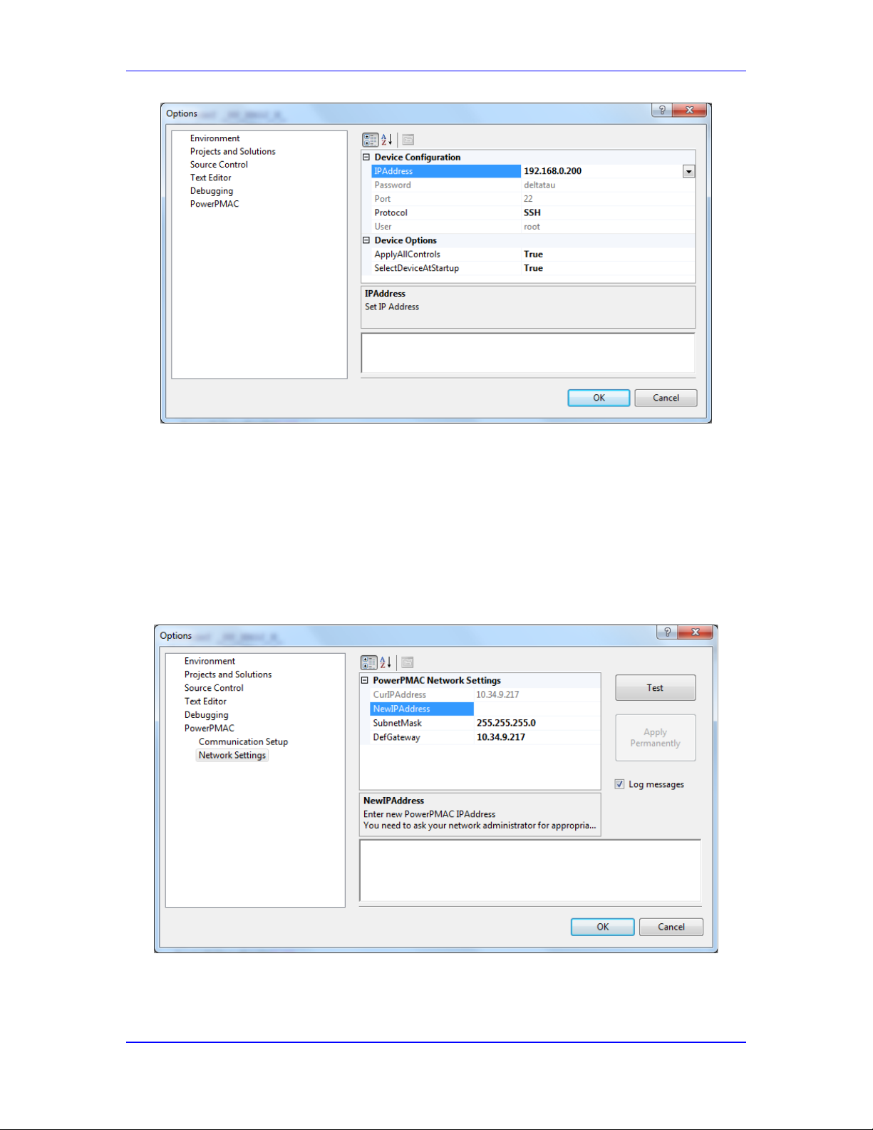
Power PMAC User’s Manual
Talking to Power PMAC 47
IDE Menu Control Window for Establishing Communications
Changing the Power PMAC IP Address
The IDE can also be used to change the IP address of the Power PMAC. To do this, select
“Tools” on the top menu bar, then “Options” from the pull-down menu. When the Options
control window appears, expand the “Power PMAC” selection and select “Network Settings”.
This will provide you with a control window (shown below) that permits you to change the IP
address. Type in your new desired IP address, then click on “Test”. If the test is successful, click
on “Apply Permanently” to make the change.
IDE Menu Control Window for Changing Power PMAC IP Address
Page 48

Power PMAC User’s Manual
Talking to Power PMAC 48
Of course, you must select an IP address that is unique on your network and will not conflict with
any other IP address. You may need to consult with your network administrator to select a
permitted address.
Finding an Unknown IP Address
If you do not know the IP address of your Power PMAC, it is of course impossible to ask for the
address using Ethernet communications. If you find yourself in this situation, you have two
methods for finding the address.
Using a Removable Memory Module
In the first method, you can get Power PMAC to copy its IP address onto a removable memory
module, either a USB memory stick or an SD memory card, which you can then read on a
separate computer.
To do this, first create a directory folder named “PowerPmacIP” at the root level on the memory
device. This is usually done on a PC. The memory device must employ the FAT32 file system,
which is by far the most common system for these devices. The folder can be left empty at this
point; no files need to be created in it. Make sure the device is safely removed from the computer
so the file system cannot be corrupted.
Install this device in your Power PMAC, and apply power to the Power PMAC to turn it on. Wait
for the boot sequence to complete – you will hear a relay click – or just allow a full minute to
elapse. Then turn off the Power PMAC and remove the memory device.
Next, install this device back in your PC and view the contents of the new “interfaces” text file in
the “PowerPmacIP” folder. This will contain the IP address. You can then use this address to
establish Ethernet communications using the IDE or your communications program (and
subsequently change this address if you wish).
Using an RS-232 Terminal Program
In the second method, you can get Power PMAC to communicate over its RS-232 port to disclose
its present IP address. If the Power PMAC does not have an RS-232 port, you can communicate
to its USB port with a USB-to- RS-232 converter.
To do this, connect a PC’s RS-232 serial port to Power PMAC’s RS-232 serial port. Start a
terminal utility program, such as HyperTerminal for Windows XP systems, or PuTTY for
Windows 7 systems, telling it to use the connected COM port. The settings for Power PMAC’s
serial port are:
115,200 baud
8 data bits, 1 stop bit
No parity
No handshake, no XON/XOFF flow control
Turn on the Power PMAC, and wait for the command prompt to appear in the terminal window.
Log in as “root”, then enter the password (“deltatau”) at the next prompt. Power PMAC will then
transmit information to the terminal window, including the IP address. You can then use this
address to establish Ethernet communications using the IDE or your communications program
(and subsequently change this address if you wish).
Page 49

Power PMAC User’s Manual
Talking to Power PMAC 49
Special Power-On/Reset Modes
On power-on or reset, Power PMAC automatically checks any present USB memory sticks or SD
memory cards for certain folder names. The existence of any of these folders at the top level
forces the Power PMAC into a special mode (known as “recovery mode”) instead of the normal
operational mode, which automatically boots and installs the project saved in flash memory.
PowerPmacNoRTLoad Folder
If a folder with the name “PowerPmacNoRTLoad” is present, Power PMAC will run as a generic
Linux computer without loading the Power PMAC application. No files need to be present in this
folder.
PowerPmacFactoryReset Folder
If a folder with the name “PowerPmacFactoryReset” is present, Power PMAC will start up in
factory reset mode, equivalent to executing a $$$*** command. In this mode, the Power PMAC
application will be loaded, but no saved project will be loaded into active memory from flash
memory. All saved setup elements will be set to factory default values. No files need to be
present in this folder.
PowerPmacConfigLoad Folder
If a folder with the name “PowerPmacConfigLoad” is present, Power PMAC will copy the
project from the files and sub-folders available in this folder to Power PMAC’s own flash
memory, replacing any existing project there. The project should be under the
“/PowerPmacConfigLoad/usrflash” sub-folder.
PowerPmacFirmwareInstallandConfigLoad Folder
If a folder with the name “PowerPmacFirmwareInstallandConfigLoad” is present, Power PMAC
will install the firmware for the Power PMAC application and copy the project from the files and
sub-folders available in this folder to Power PMAC’s own flash memory, replacing any existing
project there. The firmware should be in a file with a name like “powerpmac.deb” in the main
folder. The project should be under the “/PowerPmacConfigLoad/usrflash” sub-folder.
PowerPmacIp Folder
If a folder with the name “PowerPmacIP” is present with no “interfaces” file in the folder, Power
PMAC will automatically copy its internal interfaces file into this folder, along with a boot.log
file. This is useful if the present IP address of the Power PMAC is not known.
If a folder with the name “PowerPmacIP” is present with an “interfaces” file in the folder, Power
PMAC will use the IP address in that file for communications instead of the address in Power
PMAC’s internal interfaces file.
Page 50

Power PMAC User’s Manual
Talking to Power PMAC 50
Power PMAC Commands
The Power PMAC control application is fundamentally a command-driven device. You make
Power PMAC do things by issuing it ASCII command text strings, and Power PMAC generally
provides information to the host computer in ASCII text strings. Power PMAC provides a
powerful, flexible, and easy-to-use Script language comprised of an extensive set of commands.
There are two fundamental classes of Script commands to the Power PMAC control application:
on-line commands, and buffered program commands. These two classes of commands are
documented in separate chapters in the Software Reference Manual. It is very important to
understand the distinction between these two types of commands.
On-Line (Immediate) Commands
Many of the commands given to Power PMAC are on-line commands; that is, they are executed
immediately by Power PMAC, to cause some actions, change some variable value, or report some
information back to the host. The command itself is discarded after executing (so cannot be listed
back), although its effects may stay in the Power PMAC. These on-line commands provide a
simple but powerful interactive interface, whether the user is typing in these commands directly,
or the host computer is assembling and transmitting these commands automatically.
Note that some on-line commands are also valid as buffered program commands, so if a program
buffer is open when such a command is sent, the command will be stored in the buffer instead of
being immediately executed.
Types of On-Line Commands
There are 4 basic types of on-line commands:
1. Thread-specific commands, which only affect the action of subsequent commands on the
same communications thread
2. Motor-specific commands, which only affect the addressed or listed motor[s].
3. Coordinate-system-specific commands, which only affect the addressed or listed
coordinate system[s].
4. Global commands, whose effect is the same regardless of any addressing modes.
In the On-Line Commands chapter of the Software Reference Manual, each command is
classified into one of these types under the “Scope” descriptor.
Each type of command is discussed briefly below.
Thread-Specific On-Line Commands
In order to maintain truly independent communications among multiple communications threads,
it is necessary for certain commands that affect the operation of subsequent commands only to
affect commands in the same communications thread. For this reason, the addressing commands #n for motors and &n for coordinate systems – as well as buffer open and close commands,
affect only subsequent commands in the same thread.
Page 51

Power PMAC User’s Manual
Talking to Power PMAC 51
For example, the IDE terminal window can modally address a certain motor and coordinate
system, while the watch window, utilizing a separate communications thread, addresses a
different motor and coordinate system.
Motor-Specific On-Line Commands
A motor is addressed in a communications thread with the #n command, where n is the motor
number, with a legal range of 0 to Sys.MaxMotors - 1. This addressing is modal, so the motor
remains addressed in this thread until another #n command addresses a different motor.
It is therefore not required to precede each motor-specific on-line command with a motor
addressing command. Working in terminal mode, you may type #1j+ to start Motor 1 jogging in
the positive direction. You can then simply type j/ to stop this same motor, as Motor 1 is still the
addressed motor in the thread. However, when generating motor-specific on-line commands in
software for Power PMAC, you are strongly advised to address the motor before each command
to avoid possible intervening changes in the modally addressed motor.
Note that at power-on/reset, Motor 0 (#0) is addressed by default in all communications threads.
Since this is generally not used as a real motor, it is usually necessary to explicitly address a
motor before issuing any motor-specific commands.
Motor-specific commands include the “action” commands – enabling, disabling, jogging,
homing, open-loop output – and the “query” commands – requests for motor information such as
position, velocity, and following error.
It is possible to “list” multiple motors to be affected by a single on-line command. For example,
#2,4,6hm starts homing-search moves on Motors 2, 4, and 6 simultaneously. When multiple
motors are specified this way, the addressing is not modal; only the immediately following
command is affected. (Contrast this with #2hm#4hm#6hm, which leaves Motor 6 as the modally
addressed motor.) The #* command non-modally causes the immediately following motorspecific command to affect all active motors on the Power PMAC.
An on-line motor “action” command, such as jogging, homing, or open-loop output, is not
permitted if the motor is assigned to an axis in a coordinate system that is running a motion
program, even if the motion program is not directly commanding any axis assigned to that motor.
Such a command will be rejected with an error.
Coordinate-System-Specific On-Line Commands
A coordinate system is addressed in a communications thread with the &n command, where n is
the coordinate system number, with a legal range of 0 to Sys.MaxCoords - 1. This addressing is
modal, so the coordinate system remains addressed in this thread until another &n command
addresses a different coordinate system.
It is therefore not required to precede each motor-specific on-line command with a motor
addressing command. Working in terminal mode, you may type &1b5r to start Coordinate
System 1 execution of motion program 5. You can then simply type q to stop motion program
execution in this same coordinate system, as Coordinate System 1 is still the addressed coordinate
system in the thread. However, when generating coordinate-system-specific on-line commands in
software for Power PMAC, you are strongly advised to address the coordinate system before each
command to avoid possible intervening changes in the modally addressed coordinate system.
Page 52

Power PMAC User’s Manual
Talking to Power PMAC 52
Note that at power-on/reset, Coordinate System 0 (&0) is addressed by default in all
communications threads. Since this is generally not used as a real coordinate system, it is usually
necessary to explicitly address a coordinate system before issuing any coordinate-system-specific
commands.
Coordinate-system-specific commands include axis-definition commands (because motors are
defined to an axis in a particular coordinate system), motion-program control commands, Qvariable assignment and query commands (because Q-variables are specific to a coordinate
system), coordinate-system buffer-management commands (for kinematic, rotary, and lookahead
buffers) and axis query commands – requests for axis information such as position, velocity, and
following error.
It is possible to “list” multiple coordinate systems to be affected by a single on-line command.
For example, &1..4a aborts programs and moves for Coordinate Systems 1 through 4
simultaneously. When multiple coordinate systems are specified this way, the addressing is not
modal; only the immediately following command is affected. (Contrast this with
#1a#2a#3a#4a, which leaves Coordinate System 4 as the modally addressed coordinate
system.) The &* command non-modally causes the immediately following coordinate-systemspecific command to affect all active coordinate systems on the Power PMAC.
Global Commands
The effect of some on-line commands does not depend on which motor or coordinate system is
addressed. For instance, the command P1=1 sets the value of global variable P1 to 1 regardless
of what is addressed. Among these global commands are the global buffer-management
commands (motion-program, PLC program, and subprogram buffers), and the saving and
resetting commands.
Multiple-Variable Query and Setting Commands
With on-line commands, it is possible to use a single command to query the values of multiple
variables, or to set the values of multiple variables (to the same value). To do this, a “list” of
variables is used in the command where typically a single variable name is used.
For numbered variables (e.g. I, P, Q, M, L), the list can specify a continuous range (e.g.
P100..199, or Q0..8191), or a set of evenly spaced variables (e.g. P100,10 or
I122,5,100). In both cases, the starting variable is specified first. In the case of a continuous
range, the number of the last variable in the continuous range is specified after two periods. In the
case of a set of evenly spaced variables, the next value specified (after a comma) is the quantity
of variables in the list, and the following value (after another comma) is the numerical spacing of
the variables. If there is no following value, the spacing is taken to be 1.
For indexed data structure elements, the list can specify a set of evenly spaced indices for the
element (e.g. Motor[1].Servo.Kp,4 or Coord[2].ProgActive,6,2). The next value
specified (after a comma) is the quantity of elements in the list, and the following value (after
another comma) is the numerical spacing of the indices for the list. If there is no following value,
the spacing is taken to be 1.
Buffered Program Commands
As their name implies, Power PMAC Script buffered program commands are not acted on
immediately, but held (buffered) for later execution. Sending a buffered program command to
Page 53

Power PMAC User’s Manual
Talking to Power PMAC 53
Power PMAC merely causes the command to be loaded into the open program buffer; the
command will not actually be executed until that program is run.
Power PMAC has many Script program buffers – 1023 regular motion program buffers, 1 rotary
motion program buffer for each coordinate system, 1 forward-kinematic and 1 inverse-kinematic
program buffer for each coordinate system, 32 PLC program buffers, and 1023 subprogram
buffers.
Before commands can be entered into a program buffer, that buffer must be opened (e.g. open
prog 3, open plc 7, open subprog 1000, &3 open rotary). Note that buffered
commands can only be entered into the buffer through the same communications thread that
issued the open command. Only one communications thread at a time may have an open
program buffer.
With the exception of the rotary motion program buffers, the act of opening the buffer
automatically clears the contents of the buffer, so the next buffered program command sent
becomes the first command in the program buffer. For rotary motion program buffers, it is
possible to add commands to follow the already loaded commands after a new open rotary
command. If it is desired to clear the contents of a rotary motion program buffer, the clear
rotary command should be issued.
Note that some buffered program commands (e.g. P1=1) are also valid as on-line commands, and
will be executed as such if sent when no program buffer is open on the communications thread.
Note that some of these commands will have completely different actions as on-line or buffered
commands. Other buffered program commands (e.g. X100Y100) are not valid as on-line
commands; if such a command is sent when no program buffer is open on the communications
thread, this command will be rejected with an error.
Power PMAC Processing of Commands
The Power PMAC control application receives a Script command – on-line or buffered program –
as ASCII text embedded within one or more TCP/IP data packets. The command must be
terminated with a “carriage-return” (CR) character (ASCII value 0D hex); this control character is
what causes Power PMAC to interpret the preceding set of alphanumeric characters as a
command and to take the appropriate action.
None of the command reserved words or data-structure element names is case-sensitive in a
Script command. (Note that data-structure element names are case-sensitive in C programs.)
Comments
Any characters in a command line after a double-slash (//) are considered comments, and are
ignored by the Power PMAC. The IDE downloader treats all characters between “slash-star” (/*)
and “star-slash” (*/) as comments and will not download them to Power PMAC. However, if
Power PMAC receives these from another source, it will not recognize them as comments, and
will try to interpret them as commands, leading to errors.
Command Acknowledgement
Power PMAC acknowledges commands with the ACK character (ASCII value 07 hex) – this
character was shown as the “spade” figure in the terminal emulator examples above. (However,
Page 54

Power PMAC User’s Manual
Talking to Power PMAC 54
the commands that restart the Power PMAC – $$$ (reset), $$$*** (re-initialize), and reboot
– are not acknowledged with the ACK character.)
If the command requires no data response, only the ACK character is sent. If the command does
require a data response, this response comes before the ACK character. In this way, the ACK
character acts as an “end-of-transmission” character for any Power PMAC command response,
also indicating that any actions specified by the command have been executed.
Data Response
If the command does require a data response (i.e. an on-line “query” command), each item of the
response is provided as ASCII text followed by a carriage-return character, forming a “line” of
the response on a terminal screen. There can be multiple data response items, each followed by a
carriage-return character, forming multiple lines in response to a single command. After the last
line of the response, the ACK character is sent.
Echo Mode in Data Response
When the value of a variable or data structure element, or the definition of a pointer variable (I or
M-variable), is queried, Power PMAC can either “echo” the query command as part of the
response, or not. If the query command is echoed in the response, the response is of a form that
could then be used as a command to set the value or definition. It also makes it obvious what
command this is a response to. However, it does increase the length of transmission.
For example, with echoing enabled, the query command:
Motor[1].JogSpeed
will create a response such as:
Motor[1].JogSpeed=32
With echoing disabled, the same query command will create a response such as:
32
Each communications thread (e.g. each window in the IDE) can have its own echo mode. Many
users will want echoing enabled in the Terminal window, but not in the Watch window (where
the command is already displayed).
The echo mode for a communications thread is set by the echo n on-line command. The value
n has a range of 0 to 15 with 4 independent control bits.
Bit 0 (value 1) controls whether the command is echoed back in a query for the value of a data
structure element. If the bit is set to 1, echoing is disabled.
Bit 1 (value 2) controls whether the command is echoed back in a query for the value of a
numbered variable. If the bit is set to 1, echoing is disabled.
Bit 2 (value 4) controls whether the command is echoed back in a query for the definition of a
pointer variable. If the bit is set to 1, echoing is disabled.
Page 55

Power PMAC User’s Manual
Talking to Power PMAC 55
Bit 3 (value 8) controls whether the values of “bit-field” and “address” data structure elements are
reported as hexadecimal or decimal numbers. If the bit is set to 1, they are reported in decimal.
Bits 4, 5, and 6 control how data is reported in response to backup commands. Refer to the
description of the echo{constant} command for details.
The power-on default echo-mode value is 0, which enables echoing in all these queries, and
reports bit-field and address element values in hexadecimal. IDE control windows have a saved
echo-mode setting, which can be viewed or changed by right-clicking on the window, then
clicking on “Properties”, “Control”, and “General”.
Error Reporting for Commands
If there is an error in the command, the Power PMAC will return an error message with error
number and error type. For example:
nonsensecommand
stdin:3:1: error #20: ILLEGAL CMD: nonsensecommand
motor[333].JogSpeed
stdin:4:1: error #21: ILLEGAL PARAMETER: motor[333].JogSpeed
The following table shows the implemented command error numbers and messages:
Page 56

Power PMAC User’s Manual
Talking to Power PMAC 56
Error ID
Error Message
0..2
Reserved
3
SYSTEM FILE NOT AVAILABLE
4
Reserved
5
SYSTEM LOAD CONFIG FILE
6
SYSTEM SAVE CONFIG FILE
7
SYSTEM SEMAPHHORES NOT AVAILABLE
8
SYSTEM SHM NOT AVAILABLE
9
SYSTEM RESET TIMEOUT
10..19
Reserved
20
ILLEGAL CMD
21
ILLEGAL PARAMETER
22
PROGRAM NOT IN BUFFER
23
OUT OF RANGE NUMBER
24
OUT OF ORDER NUMBER
25
INVALID NUMBER
26
INVALID RANGE
27..30
Reserved
31
COMPILE ERR
32
BREAK POINTS SET
33
BUFFER IN USE
34
BUFFER FULL
35
INVALID LABEL
36
INVALID LINE #
37
INVALID BRKPT
38
PROGRAM RUNNING
39
NOT READY TO RUN
40
BUFFER NOT DEFINED
41
BUFFER ALREADY DEFINED
42
NO MOTORS DEFINED
43
MOTOR NOT CLOSED LOOP
44
MOTOR NOT PHASED
45
MOTOR NOT ACTIVE
46
COORD JOGGED OUT OF POSITION
47
SERVO REQUEST ACTIVE
48..49
Reserved
50
MACRO COM TIMEOUT
51
MACRO PORT NOT OPEN
52
MACRO RING SELECTED NOT AVAILABLE OR PPMAC NOT SYNCH
MASTER
53
MACRO NOT AVAILABLE, NO MACRO ICs
54
MACRO ASCII REQUEST EXCEEDED BUFFER SIZE
55
MACRO ASCII COM TIMEOUT
Page 57

Power PMAC User’s Manual
Talking to Power PMAC 57
56
MACRO RING INTEGRITY IN FAILED STATE
57
MACRO SYNC MASTER MUST HAVE STN=0
58
MACRO ASCII COM IN USE BY ANOTHER THREAD
59
MACRO MRO FILE OPEN OR READ ERR
60..69
Reserved
70
Struct Write Data Error
71
Struct Write Undefined Gate Error
72
Struct Write L Parameter Error
73
Struct Write Index Error
74
Struct Write Card ID Error
75
Struct Write Error
76
Write To Struct Address Error
77
Struct Write Gate Part Number Error
78..79
Reserved
80
MODBUS SOCKET NOT CONNECTED
81
MODBUS SOCKET BUSY
82
MODBUS SOCKET SEND/RECV ERROR
83
MODBUS SOCKET CREATE ERROR
84
MODBUS SERVER EXCEPTION ERROR
85
MODBUS SOCKET IN USE
86
MODBUS SERVER RESPONSE FORMAT ERROR
87
MODBUS SOCKET CONNECT ERROR
88
MODBUS SERVER SOCKET LISTEN ERROR
89..90
Reserved
91
MACRO STATION: ILLEGAL(I,M,P,Q) DATA_TYPE
92
MACRO STATION: ILLEGAL(I,M,P,Q) DATA_NUMBER
93
Reserved
94
MACRO STATION: REMOTE COM TIMEOUT
95
MACRO STATION: ANOTHER STATION AT THIS ADDRESS
96
UNKNOWN # & ERROR
Page 58

Power PMAC User’s Manual
Power PMAC System Configuration 58
POWER PMAC SYSTEM CONFIGURATION
Power PMAC systems have extensive capabilities for automatically identifying and selfconfiguring their systems. This is particularly important for Power UMAC systems, with their
wide variety of configurations. These capabilities provide the user with ease of use and flexibility
in getting started with a particular configuration.
Processors (CPUs)
Different Power PMAC platforms use a variety of processors. For many purposes, the differences
between these processors are invisible to the user. However, there are a few reasons why it may
be important to understand which CPU family is used.
Power PC
The first Power PMAC implementations have processors that use the Power PC architecture.
These include the AMCC 460EX single-core CPU and the AMCC 465 (APM86xx) single or
dual-core CPU.
ARM
Newer embedded Power PMAC controllers have processors that use the ARM architecture. These
include the Freescale 1021A dual-core CPU and the Freescale 1043A quad-core CPU.
X86
Omron Industrial PCs (IPCs) with PMAC firmware installed have processors that use the “x86”
architecture. This include the Intel i7 and Celeron CPUs.
Memory
Power PMAC systems use both active and non-volatile memory. It is important to understand
how they work together.
Active Memory (RAM)
Power PMAC systems use standard double data rate (DDR) synchronous dynamic random-access
memory (RAM) modules for active memory. The standard RAM capacity is 1 GB. In most Power
PMAC products, larger capacities (usually 2 GB) are available as options.
Non-Volatile Memory (Flash)
The Power PMAC uses non-volatile flash memory to store information while electrical power is
not applied. Specific user operations are required to write to flash memory.
NOR flash
Embedded Power PMACs use a NOR flash IC to store the Linux operating system. The user does
not write to the NOR flash in any normal operation.
NAND flash
Power PMACs use NAND flash “solid-state disks” (SSDs) to store user application information
when power is not applied.
Page 59
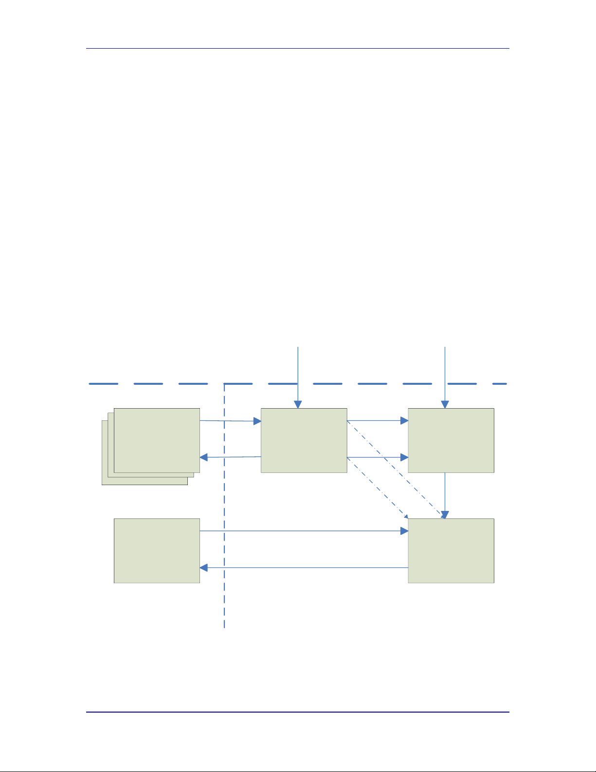
Power PMAC User’s Manual
Power PMAC System Configuration 59
Use of Memory in Power PMAC Applications
It is important to understand how the active memory (RAM) and non-volatile memory (flash) are
used in Power PMAC applications. The application is developed interactively as a “project” in
the Integrated Development Environment (IDE) software running on a PC.
Downloading the Project to Active Memory
When you are ready to try the project on the Power PMAC, you “download” the project from the
PC to the Power PMAC, or “build and download” if there are C routines or applications to be
compiled as part of the project.
The first step in this process simply copies the project files with Script commands from the PC
into a directory (/var/ftp/usrflash) in Power PMAC’s RAM. If there are C routines or applications,
the IDE cross-compiles them for the Power PMAC processor, and transfers the executable code
files. The source code files are not transferred to the Power PMAC in the default project
configuration. However, the project properties can be changed to include the source code files in
the download
The second step is to internally issue the PMAC Script commands (both on-line and buffered
program) just as if they had been externally issued from the terminal command window. This can,
and usually does, include commands to set the values of savable setup elements. The project is
now ready for execution.
Active
Project
Files
/var/ftp/usrflash/
Program &
Table
Buffers
Saved
Setup
Elements
/usrflash/projects/
configuration/ppsave.cfg
Active
Setup
Elements
)1(Reset
)1(save
)2(save
)2(Reset
PowerPMAC
erHostComput
)2(Download
)3(Re set
)1(
Pr
Download
oject
Commands
Commands
Memory
Flash
volatileNon
RAM
Active
Volatile
Saved
Project Files
/opt/ppmac/usrflash/
Power PMAC Project Download, Save, and Reset Processes
Page 60

Power PMAC User’s Manual
Power PMAC System Configuration 60
Saving the Project to Flash Memory
If you wish to store your project to non-volatile memory so you can cycle power and not need to
download again from the IDE, you can issue the save command. This first causes the present
active values of all savable setup elements to be copied into a file in flash memory. Then all of
the active project files in RAM are copied into a corresponding directory in flash memory.
Note that if you transfer any programs, tables, etc. to the Power PMAC outside of the project (for
example, a CNC “part program” that is only intended to be used temporarily), it will not be
copied to flash memory in a save operation.
Resetting the Power PMAC
When Power PMAC is reset, either by cycling power or by a $$$ reset command, the saving
process is essentially reversed. First, the saved values of the setup elements are copied back into
their active registers.
Second, the most recent set of project files that has been saved in flash memory is copied into the
matching directory in active memory, just as it would have been in the download process from
the PC IDE program.
Third, the PMAC Script commands (on-line and buffered program) in these files are internally
issued, just as in the download process. Note that if any of the on-line commands in a file set the
value of a saved setup element, this will overwrite the value that was just copied directly from
flash memory for that element.
Re-Initializing the Power PMAC
If the Power PMAC is re-initialized by a $$$*** command, the values of all saved setup elements
are set to factory defaults, and no project is loaded into active memory. If there is a project stored
in flash memory, it is not lost – it just is not loaded into active memory. It can subsequently be
loaded into active memory on a normal reset.
If there is an error on a normal power-on/reset event, including a change in the hardware
configuration since the last save operation, the Power PMAC is re-initialized instead, just as with
an explicit re-initialization command. A previously saved project is not loaded into active
memory, but it is not lost.
Physical Configuration Status Reporting
On any power-up or reset, including re-initialization, the Power PMAC processor automatically
queries all possible interface addresses to see what hardware configuration is present in the
system. Information as to what is found is stored in software data structures that are accessible by
the user. This information is used by smart setup software in the Integrated Development
Environment (IDE) software to help guide the user through the setup choices that are possible
within a given hardware configuration. It is also possible for the user to access this information
directly, but this is generally not necessary for the execution of an application – it is mostly used
for troubleshooting.
General Configuration
A Power PMAC system can report key aspects of its configuration to the user. Typically the best
way to see this information is in the “CPU Information” window of the IDE’s Task Manager
(selected from the “Tools” menu). A sample is shown here:
Page 61
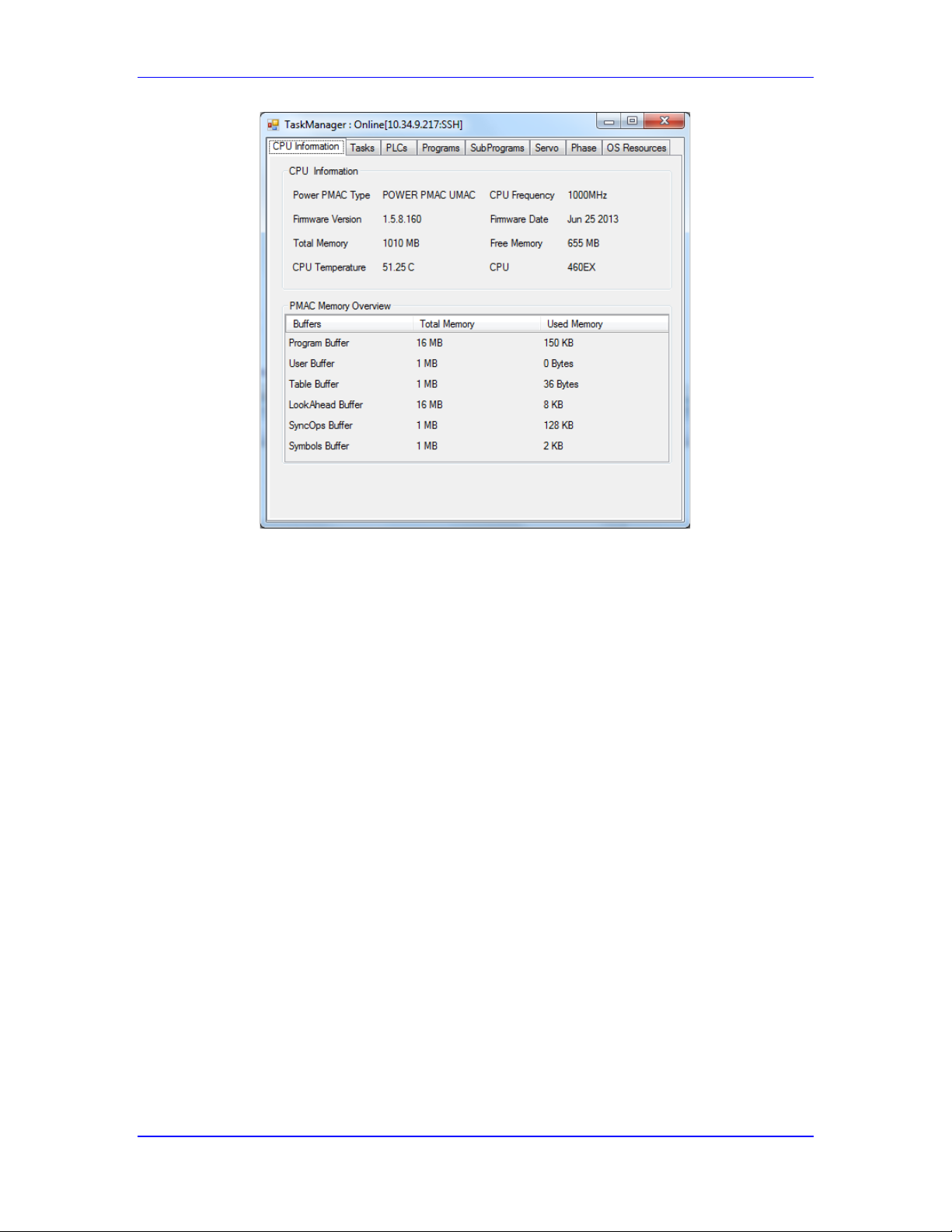
Power PMAC User’s Manual
Power PMAC System Configuration 61
Sample IDE Task Manager CPU Information Window
This window uses several basic query commands to obtain its information, such as cpu, type,
vers, date, and free.
Interface ICs Present
Power PMAC will report the interface ICs (“Gates”) of each type that it has found in the
following status data structure elements:
Sys.Gate1AutoDetect DSPGATE1 PMAC2-style Servo ICs
Sys.Gate2AutoDetect DSPGATE2 PMAC2-style MACRO ICs
Sys.Gate3AutoDetect DSPGATE3 PMAC3-style machine interface ICs
Sys.CardIoAutoDetect IOGATE (or equivalent) PMAC2-style I/O ICs
Sys.CardDPRAutoDetect Dual-ported RAM ICs
Each of these variables is a bit field. Bit i of the variable is set to 1 if the IC of that index number
has been detected, to 0 if it has not. For example, if Sys.Gate1Autodetect had a value of $150,
where bits 4, 6, and 8 were set to 1, this means that DSPGATE1 IC represented by data structures
Gate1[4], Gate1[6], and Gate1[8] were detected, and no others.
Note that the old ACC-11E UMAC digital I/O card cannot be auto-detected by the processor,
even though it has an IOGATE IC, because it lacks the circuitry required for auto-detection.
Interface IC Addresses
In addition, Power PMAC will report the offset from the start of memory-mapped I/O (which is
found in Sys.piom) of the base address of each interface IC it finds in the following status data
structure elements:
Page 62

Power PMAC User’s Manual
Power PMAC System Configuration 62
Sys.OffsetGate1[i] Base address offset of Gate1[i] DSPGATE1 IC
Sys.OffsetGate2[i] Base address offset of Gate2[i] DSPGATE2 IC
Sys.OffsetGate3[i] Base address offset of Gate3[i] DSPGATE3 IC
Sys.OffsetCardIo[i] Base address offset of I/O IC
Sys.OffsetCardDPR[i] Base address offset of dual-ported RAM IC
These address offsets can be useful for creating pointer variables in C to hardware registers in the
ICs. The (absolute) register address is the sum of Sys.piom, this base address offset, and the
register offset from this base (which can be found in the Power PMAC ASIC Register Element
Addresses chapter of the Software Reference Manual). A value of 0 is reported for any IC not
found.
Note that many of the PMAC2-style digital I/O cards can be represented by the GateIo[i] data
structure, but the analog I/O cards cannot. They must be represented by their own data structures,
such as Acc28E[i], Acc36E[i], and Acc59E[i].
Interface IC Configuration Information
For each interface IC auto-detected, Power PMAC will provide information in data structure
elements about the hardware configuration present with the IC, as each type of IC can be used in
several different configurations:
For PMAC2-style ICs, these status elements are:
Gaten[i].PartNum Accessory 6-digit Delta Tau part number
Gaten[i].PartOpt Option code for accessory configuration
Gaten[i].PartRev Revision number of accessory
Gaten[i].PartType Interface class of accessory
Here, n is ‘1’ for DSPGATE1 ICs, ‘2’ for DSPGATE2 ICs, and ‘Io’ for IOGATE ICs. The same
status elements are available for the Acc28E[i], Acc36E[i], and Acc59E[i] analog I/O structures.
For PMAC3-style ICs, these status elements are:
Gate3[i].PartNum Accessory 6-digit Delta Tau part number
Gate3[i].PartOptn Option code for accessory component n configuration
Gate3[i].PartRev Revision number of accessory
Gate3[i].PartType Interface class of accessory
Change in Configuration
If, during the auto-detection process at power-on/reset, the Power PMAC CPU discovers that the
physical configuration is different from the configuration that was present the last time a save
command was issued to store configuration and project information to non-volatile flash memory,
it will automatically set the Sys.HWChangeErr status bit and re-initialize the system to factory
defaults.
This detection of a configuration change can occur if a card has been added or removed, or if
there is a hardware problem that prevents something in the configuration from being detected
properly. The re-initialization is performed because it is very likely that the saved settings and
project are no longer appropriate for safe and effective operation.
Page 63

Power PMAC User’s Manual
Power PMAC System Configuration 63
Power PMAC System Clock Source
In a Power PMAC system, the system phase and servo clocks, which interrupt the processor and
latch key input and output data for the servos, come from one (and only one) of the Servo ICs or
MACRO ICs in the system. There must be a unique source of the phase and servo clocks for an
entire Power PMAC system. This section explains how to specify that clock source. A later
section of this chapter, Setting System Clock Frequencies, explains how to set the frequencies
once the source has been determined.
CPU Self Clocking
Note that in a system with no Servo or MACRO ICs, it is possible to have the processor generate
its own timer-based interrupts. This can be used for network-based servo interfaces such as
EtherCAT, or for simulation purposes. Saved setup element Sys.CpuTimerIntr should be set to
1 in this case.
The CPU cannot output servo or phase clock signals, so if there are Servo ICs and/or MACRO
ICs in this setting, their hardware operation will not be synchronous to the software operation of
the CPU.
Default Clock Source
The re-initialization (factory-default) source for these clock signals is appropriate in almost all
applications. Only in specialized cases will another source be used. The Power PMAC Setup
control in the Integrated Development Environment (IDE) software will walk you through the
setup of the frequencies for the source selected (setting the frequencies is discussed in the next
section).
IC Clock Generation Facilities
Each PMAC2-style Servo IC (DSPGATE1 IC), PMAC2-style MACRO IC (DSPGATE2 IC), and
PMAC3-style machine-interface IC (DSPGATE3 IC with both servo and MACRO circuitry) has
the capability for generating its own phase and servo clock signals, or for accepting external
phase and servo clock signals. Only one of these ICs in a system may generate its own clock
signals; the others must accept an external signal.
Note that it is strongly recommended that all Servo and MACRO ICs in the system be set up for
the same phase and servo clock frequencies as the IC that is generating the system clock signals.
When these ICs are set up to receive external clock signals, they are still generating internal clock
frequencies, but are pulled into synchronization with the external signals through phase-lockedloop (PLL) circuits. Intermediate signals, such as those used in PWM generation, operate better if
the PLLs are only making small corrections.
Page 64
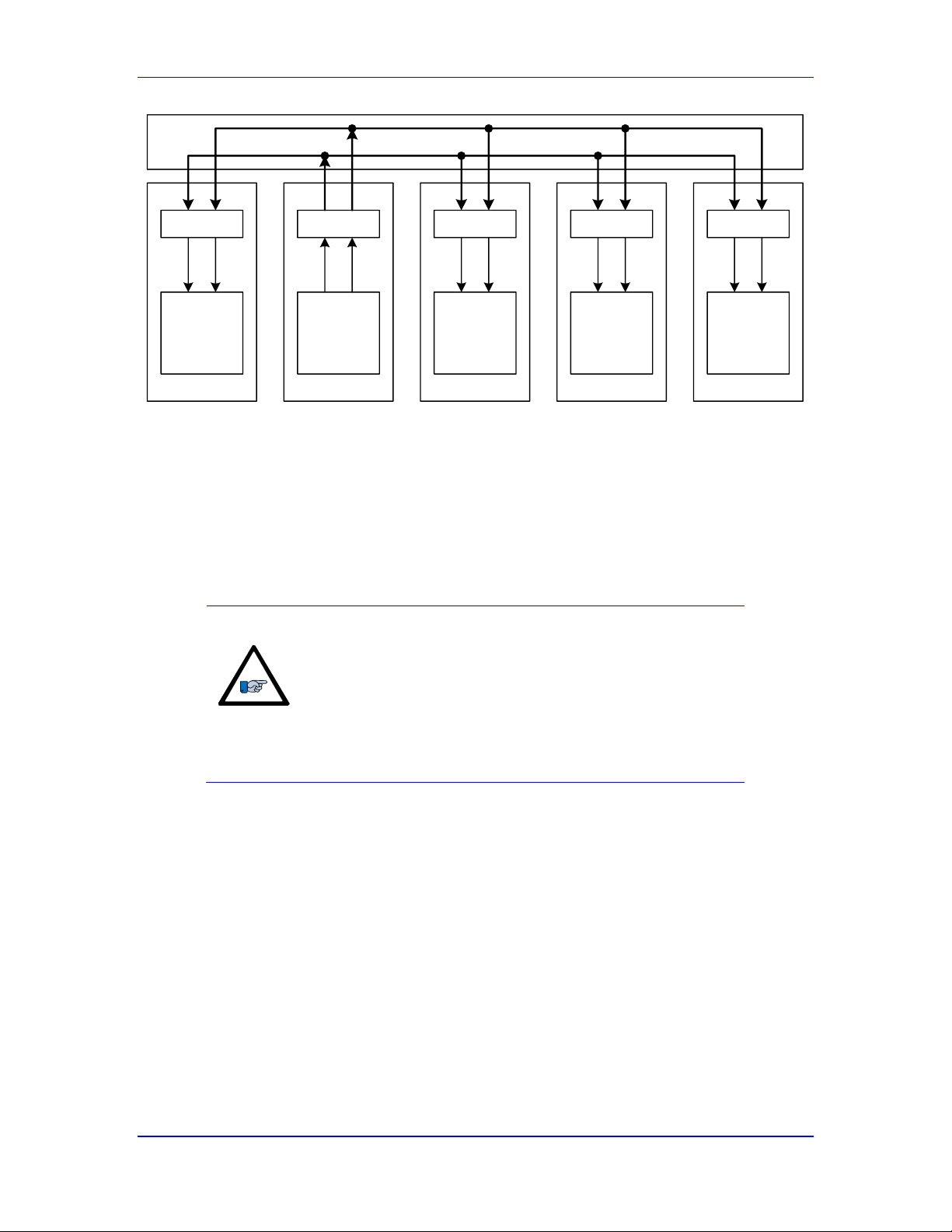
Power PMAC User’s Manual
Power PMAC System Configuration 64
CPU
DSPGATEn
PSD = 0
DSPGATEn
PSD = 3
DSPGATEn
PSD = 3
IOGATE
Buffer
Bi-dir. Buffer
Bi-dir. Buffer Bi-dir. Buffer
Buffer
Servo Clock
Phase Clock
PSD: Gaten[i].PhaseServoDir
Power PMAC System Clock Generation Example
Saved setup element Gaten[i].PhaseServoDir controls the “direction” of the clock signal for
each of these DSPGATEn ICs. If the variable value is 0, the IC generates its own clock signals
and outputs them. If the variable value is 3, the IC accepts the clock signals from a source
external to it. Only one of these ICs can have this variable at a value of 0; the rest must be set to
3.
Note
If more than one of these ICs is set up to use its own clock
signals and to output them, the processor will be interrupted by
multiple sources and will not operate normally – it is possible
that the watchdog timer will trip. (Because the outputs are
open-collector types, there will be no hardware damage from
signal contention, but system software operation will be
compromised.)
EtherCAT Network Distributed Clocks
If the Power PMAC is commanding servo drives over an EtherCAT network, the network must
be put in “distributed clock” (DC) mode to keep the controller and the drives fully synchronized.
Otherwise, the different devices on the network will gradually drift apart over time because each
device’s reference frequency will be slightly different. This drift can manifest itself as periodic
glitches in the motion each time the drift goes past a full network cycle.
With the Etherlab EtherCAT stack (Sys.EcatType = 0), ECAT[i].DistrClocks must be set to 1 to
enable DC mode. With the Acontis EtherCAT stack (Sys.EcatType = 1), the EtherCAT Network
Information (ENI) initialization file created by the configuration program must contain the
command to enable DC mode.
Shift Mode Selection
In DC mode, one of the devices on the network is configured to provide the reference clock, and
the other devices must be configured to adjust their own clock settings to maintain
Page 65

Power PMAC User’s Manual
Power PMAC System Configuration 65
synchronization. If the reference device is the EtherCAT master (Power PMAC), all of the slaves
must adjust; this is called “bus shift mode”. If the reference device is one of the slaves, the master
must adjust; this is called “master shift mode”.
In most configurations, either bus shift or master shift mode can be used. However, some
EtherCAT slave devices do not synchronize properly in one or the other mode, and this can force
the user to choose a particular mode for the network. If Power PMAC is the master on multiple
EtherCAT networks simultaneously, all of the networks must be operated in bus shift mode.
Bus Shift Mode
In bus shift mode, all of the slave devices must be configured to adjust their clock settings
dynamically; each type of device has its own particular details for configuration. Power PMAC
must be configured for bus shift mode by setting ECAT[i].DCRefMaster to 1. In this mode,
none of the clock adjustment settings in Power PMAC is used.
Master Shift Mode
Power PMAC is configured for master shift mode by setting ECAT[i].DCRefMaster to 0. It also
must be configured to specify which slave it gets its synchronization signal from. With the
Etherlab stack, ECAT[i].DCRefSlave must be set to the number of the slave. With the Acontis
stack, the initialization file created by the configuration program must specify the slave.
In master shift mode, the Power PMAC must be set up to specify how it will adjust its servo
clock frequency to stay synchronized to the reference slave. There are two adjustment methods.
The first method is a PID feedback algorithm that has variable adjustments each cycle. The
second method is a hysteresis loop with a fixed adjustment rate outside of a deadband.
Both of these methods can be used whether the servo clock is generated by a Servo or MACRO
ASIC, or by the processor itself. If the servo clock is generated by a DSPGATE1 or DSPGATE2
IC, the value in Gaten[i].PwmPeriod is adjusted. If the servo clock is generated by a
DSPGATE3 IC, the value in Gaten[i].PhaseFreq is adjusted. If the servo clock is generated
inside the processor, the value in an internal timer register (originally set from Sys.ServoPeriod)
is adjusted.
The PID algorithm is selected by setting the proportional (P) gain term ECAT[i].DCKp greater
than 0.0. Then the integral (I) gain term ECAT[i].DCKi, derivative (D) gain term
ECAT[i].DCKd, integration limit ECAT[i].DCiLimit, and maximum correction
ECAT[i].DCMaxAdjust are used as well. The default settings of these terms work well for most
configurations.
The hysteresis loop is selected by setting ECAT[i].DCKp to 0.0 (not its default). Then the fixed
adjustment rate terms ECAT[i].DCRefPlus and ECAT[i].DCRefMinus, and deadband
ECAT[i].DCRefBand are used. The default settings of these terms work well for most
configurations.
Distribution of Clock Signals
Whatever the source of the phase and servo clock signals, these signals must be available to the
processor and all Servo ICs and MACRO ICs, plus any other circuits that use these signals in
their functioning (such as I/O cards that are used for parallel or serial feedback). Note that the
“hardware clock” signals – the DAC clock, ADC clock, encoder sample clock, and PFM clock –
are generated locally inside each Servo IC and MACRO IC, and are not shared between ICs.
Page 66

Power PMAC User’s Manual
Power PMAC System Configuration 66
In Power UMAC systems, the phase and servo clocks are shared across the “UBUS” backplane
board in differential format among the different 3U-format cards inserted into that backplane.
Each card has differential buffer ICs for these signals as they interface to the backplane. On cards
that are potential sources of the phase and servo clock signals, such as the ACC-24E/C axis
boards or the ACC-5E MACRO board, these buffers can be configured as either inputs or
outputs.
On each UMAC board with a PMAC2-style Servo IC that could be a clock source, there is a
jumper that controls the configuration of the clock-direction buffers. In one setting, the board can
only input the clock signals. This setting is required for the older UMAC MACRO, in which the
clock signals always come from the MACRO interface board. It is permissible, but not
recommended, for boards in UMAC Turbo systems that will be not be generating their own phase
and servo clock signals. This setting is not permissible for the UMAC board that is generating the
system phase and servo clocks.
In the other setting (the factory default setting), the direction of the clock-signal buffers can be
reversed by the CPU. This setting is required for the board that is generating the system clocks; it
is recommended for the other boards as well (so the source can be changed without moving any
buffers). At power-up/reset, the CPU will configure the buffers the board containing the Servo IC
or MACRO IC that is specified by the saved configuration to generate the system clocks as
outputs to the UBUS backplane; it will configure the buffers on all other boards to be inputs from
the UBUS backplane.
Re-Initialization Clock Actions
On re-initialization of a Power PMAC system with the $$$*** command, the CPU searches all
possible locations of Servo ICs and MACRO ICs to see which are present. It selects one as the
clock source based on the following priority:
1. Lowest-numbered PMAC3-style IC MACRO interface found
2. Lowest-numbered PMAC2-style IC MACRO interface found
3. Lowest-numbered PMAC3-style IC Servo or I/O interface found
4. Lowest-numbered PMAC2-style IC Servo interface found
It will set the Gaten[i].PhaseServoDir element for this IC to 0, and for all of the other ICs to 3.
The global status element Sys.ClockSource indicates the type and index of the selected IC.
Normal Reset Clock Actions
On a normal power-up or reset sequence, the Power PMAC CPU reads the configuration
information that was previously saved to flash memory and sets the Gaten[i].PhaseServoDir
elements for each IC to the appropriate value. If there are bi-directional clock-signal buffers
whose directions need to be set, the CPU will automatically do this as well.
If the hardware configuration the CPU finds on power-up/reset is not the same as that in the last
valid saved configuration, the Power PMAC will come up in an error condition, setting global
status bit Sys.HWChangeErr to 1. In this case, the user must make the software system
configuration match the new hardware configuration (usually by using the $$$*** re-
initialization command), save this configuration, and reset the system before proceeding.
Page 67

Power PMAC User’s Manual
Power PMAC System Configuration 67
If the CPU does not receive phase and servo clock signals after it configures the Servo and
MACRO ICs and bi-directional clock buffers, it will come up in an error condition not permitting
control, and set global status bit Sys.NoClocks to 1.
Changing the Clock Source from Default
In the rare event it is desired to select a clock source that is different from that automatically
selected on system re-initialization, a simple procedure can be followed. This entails changing
directions of the clock signals of the old and new source ICs. This must be done with multiple
commands on a single command line, so there is no period when there is a double clock source or
no clock source, either of which could cause a watchdog timer trip.
The change involves changing the setting of Gaten[i].Chan[j].PhaseServoDir for the default
source from 0 to 3 and for the new source from 3 to 0. In addition, for any PMAC2-style
DSPGATE1 IC (as on an ACC-24E2x board) or DSPGATE2 IC (as on an ACC-5E board), a
separate parameter Cid[x].Dir must be changed as well to turn around the direction of an external
bi-directional buffer IC. (This is done automatically with PMAC3-style DSPGATE3 ICs.)
Cid[x].Dir must be set to 0 when the IC is not a source, so it can accept the clock signals as
inputs, and to 1 when the IC is a source, so it can output the clock signals. The Software
Reference Manual chapter Power PMAC I/O Address Offsets has a table of the x index values for
all Gaten[i] IC values. The most commonly used are Cid[2] for Gate1[4] and Cid[4] for
Gate2[0].
For example, to change the clock source from an ACC-5E at Gate2[0] to an ACC-24E3 at
Gate3[0], the following command line could be used:
Gate3[0].PhaseServoDir=0 Gate2[0].PhaseServoDir=3 Cid[4].Dir=0
These changes must be saved to maintain the settings through a reset or power cycle. After this,
global status element Sys.ClockSource should reflect the IC you have chosen as the source of the
system clocks. (If it reports a negative value, you have multiple clock sources, and you must
correct this before you can continue.)
Page 68

Power PMAC User’s Manual
Power PMAC System Configuration 68
Setting System Clock Frequencies
The phase clock and servo clock signals set the “heartbeat” for the entire Power PMAC system,
synchronizing both hardware and software operations. While the factory default frequencies –
9.04 kHz for the phase clock and 2.26 kHz for the servo clock – are suitable for most
applications, some applications will either require changes, or could benefit from changes in one
or both of these frequencies. Factors that go into the decision as to what frequencies to select are
covered in the chapters on commutation and servo-loop closure. In general, higher frequencies
can lead to higher performance (although there are points of diminishing returns, and other
system limitations can cap performance no matter how fast the Power PMAC is running), at the
cost of increase processor usage
Phase and Servo-Clock Hardware Tasks
The hardware tasks that are driven by the phase and servo clock signals include:
Latching of encoder counters (phase and servo clocks)
Latching of parallel feedback registers (phase or servo clock)
Strobing of serial encoders and latching of resulting data (phase or servo clock)
Strobing of A/D converters and latching of resulting data (phase clock)
Output to D/A converters (phase clock)
Output to PWM circuits (phase clock)
Communication over MACRO ring (phase clock)
Phase-Clock Software Tasks
The software tasks that are driven by the phase clock signal include:
“Servo-in-phase” updates: sub-interpolation and loop closure for fast-tools
Digital current loop closure
Motor phase commutation
Demuxing of muxed A/D converters
Phase data gathering
Note that there are no phase tasks executed on PMACs that do not support Servo or MACRO ICs
(e.g. CK3Es, IPCs).
Servo-Clock Software Tasks
The software tasks that are driven by the servo clock signal include:
Encoder conversion table pre-processing
Trajectory (fine) interpolation
Position following (electronic gearing) calculations
Compensation table and cam table update
Position/velocity loop closure
Motor commanded move (jog) equation calculations
Motor status/error checks: following error, desired velocity zero, in position
EtherCAT cyclic data transfers (if enabled)
Servo data gathering
Page 69

Power PMAC User’s Manual
Power PMAC System Configuration 69
While most users do not need to know the specific order of tasks within the servo interrupt,
advanced users, especially those writing custom algorithms, may find this information useful. The
order of tasks is:
1. EtherCAT cyclic input transfers (if enabled), loading input data including servo feedback
into ECAT[i].IO[k].Data memory holding elements.
2. Encoder conversion table pre-processing of feedback and master data, starting with the
entry whose index is specified by Sys.FirstEnc and continuing in numerical order until
the first entry with EncTable[n].type = 0.
3. Update raw actual positions (Motor[x].Pos, Pos2) for all active motors, from lowest to
highest numbered. For each:
a. Read encoder conversion table results and add into previous cycle’s position
b. Update buffers for filtered velocity calculations
4. Update cam table and compensation table outputs for all active tables
5. Update commanded position for all active motors, from lowest to highest numbered. For
each:
a. Compute master position following, if enabled
b. If pending motor move command (jog or home), calculate trajectory equations
c. Update computed move trajectory
d. Execute trajectory pre-filter if enabled
e. Store combined and filtered value into Motor[x].DesPos
6. Servo loop update for each active motor, from lowest to highest numbered. For each:
a. Add in compensation and backlash position corrections to raw actual positions to
get net actual positions Motor[x].ActPos, ActPos2
b. Compute intermediate values Motor[x].PosError, DesVel, ActVel for servo
algorithm
c. Update status for following error, desired-velocity-zero, and in-position
d. Call selected (built-in or custom) servo algorithm
e. Offset and clamp returned servo output value as needed
7. Update time-base (%) value for each active coordinate system, from lowest to highest
8. EtherCAT cyclic output transfers (if enabled), transmitting output data including servo
commands from ECAT[i].IO[k].Data memory holding elements over the network.
9. Servo data gathering
*Can be delayed until after some motor loop closures with non-zero value for Sys.CompMotor
Real-Time Interrupt Software Tasks
The “real-time interrupt” in Power PMAC is a software interrupt that occurs every
(Sys.RtIntPeriod + 1) servo interrupts. At the end of the servo tasks for these cycles, the realtime interrupt software tasks are performed. These include:
Page 70
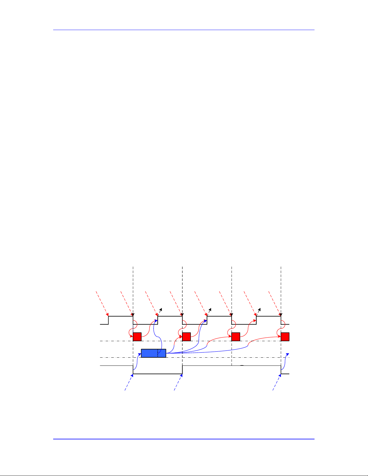
Power PMAC User’s Manual
Power PMAC System Configuration 70
Foreground PLC and CPLC execution
Motion program move planning
Trajectory coarse interpolation (segmentation)
Kinematic transformations
Buffered lookahead calculations
Motor safety and status checks*
o Hardware and software overtravel limit checks
o Amplifier enable and fault handshaking
o Encoder-loss and auxiliary-fault checks
o Integrated current (I2T) checks
o Brake release/engage delay calculations
o Backlash compensation calculations
o Triggered move trigger check and software position capture
o General status updates
Coordinate system status updates
Watchdog timer update
*Can specify the number of motors to execute these checks each RTI with Sys.MotorsPerRtInt.
Phase and Servo Hardware and Software Synchronization
In Power PMAC systems with Servo an MACRO Interface ICs, the hardware and software are
very tightly coordinated to minimize delays between feedback and output, and to minimize the
variation in delays as well.
The following diagram shows how key phase and servo clock hardware and software tasks are
coordinated:
Phase
Clock
Servo
Clock
Phase
Tasks
Servo
Tasks
Strobe
Serial
Phase*
Feedback
Strobe
Serial
Phase
Feedback
Strobe
Serial
Phase
Feedback
Strobe
Serial
Phase*
Feedback
Latch
Data
Into
Registers
Latch
Data
Into
Registers
Latch
Data
Into
Registers
Latch
Data
Into
Registers
Latch
Data
Into
Registers
Strobe
Serial
Servo
Feedback
Interrupt
CPU
Interrupt
CPU
Interrupt
CPU
Interrupt
CPU
Output
Cmd
Signals
Output
Cmd
Signals
Output
Cmd
Signals
Latch
Data
Into
Registers
[1]
[1]
[2]
[2] [2]
[1] Servo command for motors not
commutated by PMAC
[2] Servo command for motors
commutated by PMAC
*Can be used for servo as well
Power PMAC Hardware/Software Synchronization
Page 71

Power PMAC User’s Manual
Power PMAC System Configuration 71
Strobing and Latching Feedback Data
Feedback data that can be read directly by the processor, such as incremental encoder counter
data, is latched on the falling edge of the phase or servo clock signal. This edge is also the
interrupt to the CPU, which will be able to use this data almost immediately in its software tasks.
Feedback devices that provide data to the Power PMAC serially, such as serial-protocol encoders,
serial ADCs, and the MACRO ring, must be strobed earlier than these interrupt-causing clock
edges to provide time for the full data transfer before the interrupt, at which time the data is
latched into processor-readable registers. Usually, these are strobed on the preceding rising edge
of the phase clock, meaning that there is an added one-half phase cycle delay in using this data.
Some of the serial encoder and serial ADC interfaces permit the strobing to be delayed somewhat
past this clock edge, permitting a reduction the time delay before use at the CPU interrupt. The
serial encoder interfaces permit the strobing to occur on the previous falling edge of the phase
clock, or on either edge of the servo clock, if there is not enough time to transmit the data in onehalf phase cycle.
Phase and Servo Software Execution
On the falling edge of the phase clock signal, the CPU is interrupted and it starts executing its
phase software tasks. The CPU is expecting that any feedback data be immediately available for it
to read. The command outputs for each motor are written directly to the specified registers after
they are computed.
When the phase tasks are completed in any cycle where the servo clock signal is low, the servo
software tasks immediately start. As each motor’s servo loop is executed, if the motor is not
commutated by PMAC, its command output is written directly to the specified register at this
time. (See arrows marked [1].) If the motor is commutated by PMAC, its command output is held
in memory for use by the commutation algorithm that starts in the next phase clock cycle. This
value may be used as input to the commutation algorithm in multiple phase cycles. (See arrows
marked [2].)
Transmission of Command Data
Command data, whether from a phase or servo task, that has been written to Delta Tau Servo and
MACRO ICs is transferred from the CPU-addressed registers to the working circuitry on the
rising edge of the phase clock signal.
In virtually all applications, the phase tasks for all motors will complete before the rising edge of
the phase clock, so there is only a one-half phase cycle delay from the start of computation to the
start of transmission. If the phase tasks for any motor complete after this rising edge, the
command values will not be transmitted until the next rising edge, resulting in a one-and-one-half
cycle delay. (This is very rare.)
In many applications, the servo tasks for all motors will complete before the first rising edge of
the phase clock. In this case, for motors not commutated by PMAC, command transmission will
start at this first rising edge. If there are the default 4 phase cycles per servo cycle, there will be a
1/8-servo-cycle delay from the start of computation to the start of transmission. If the servo tasks
for any motor not commutated by PMAC complete after this rising edge, the command values
will not be transmitted until the next rising edge. With 4 phase cycles per servo cycle, this results
in a 3/8-servo-cycle delay.
Page 72

Power PMAC User’s Manual
Power PMAC System Configuration 72
For a motor commutated by PMAC, if the servo tasks for a motor are completed by the next
falling edge of the phase clock, the servo command output is used as an input to the commutation
algorithm in this next phase cycle. If the servo tasks for a motor are not completed by this edge,
the servo command output will not be used until the following phase cycle.
Background Tasks
For “single-core” versions of the CPU, in the time available between cycles of the above tasks,
the Power PMAC processor performs background tasks, both those controlled by Power PMAC’s
scheduler, and independent applications running under the general-purpose operating system
(GPOS).
For “multi-core” versions of the CPU, in the default configuration, the interrupt-driven tasks
listed above execute in one core, and the background tasks execute simultaneously in a separate
core.
The Power PMAC scheduled software tasks running in background include:
Background Script PLC programs
Background C PLC programs
General housekeeping and status updates
Watchdog timer reset
In Power PMACs with “kernel mode” operation (UMAC, Clipper, Brick, CK3M), each
background cycle, Power PMAC repeats a loop of executing one scan of one active background
Script PLC program, then one scan of all active background C PLC programs until all of the
active background Script PLC programs have executed, followed by one pass of the background
housekeeping and status update tasks.
In Power PMACs with “Posix mode” operation (CK3E, Sysmac IPC, NJ/NX PLC), each
background cycle, Power PMAC repeats a loop of executing one scan of one active background
Script PLC program, followed by one pass of the background housekeeping and status update
tasks.
In either case, when a background cycle is complete, the Power PMAC background scheduler
“sleeps” for an interval to provide time for independent applications and GPOS tasks (including
the “gpascii” communications threads) to run. The “sleep” interval is set by saved setup
element Sys.BgSleepTime, and can range from 0.25 milliseconds to 10.0 milliseconds, with a
default of 1.0 millisecond.
Page 73
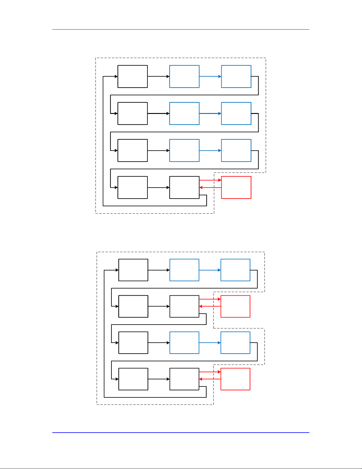
Power PMAC User’s Manual
Power PMAC System Configuration 73
This diagram shows the background process flow for “kernel mode” Power PMACs:
Script
PLC 1
Background
CPLC 1
Background
CPLC 2
Script
PLC 2
Background
CPLC 1
Background
CPLC 2
Script
PLC 3
Background
CPLC 1
Background
CPLC 2
House-
keeping
Background
Sleep Time
C Apps,
GPOS
PMAC Scheduled Background Tasks
Independent
OS Tasks
“Kernel Mode” Power PMAC Example Background Cycle
This diagram show the background process flow for “Posix mode” Power PMACs:
Script
PLC 1
Background
CPLC 1
Background
CPLC 2
Script
PLC 2
Script
PLC 2
Background
CPLC 1
Background
CPLC 2
House-
keeping
Background
Sleep Time
C Apps,
GPOS
PMAC Scheduled Background Tasks
Independent
OS Tasks
Background
Sleep Time
C Apps,
GPOS
Independent
OS Tasks
House-
keeping
“Posix Mode” Power PMAC Example Background Cycle
Page 74
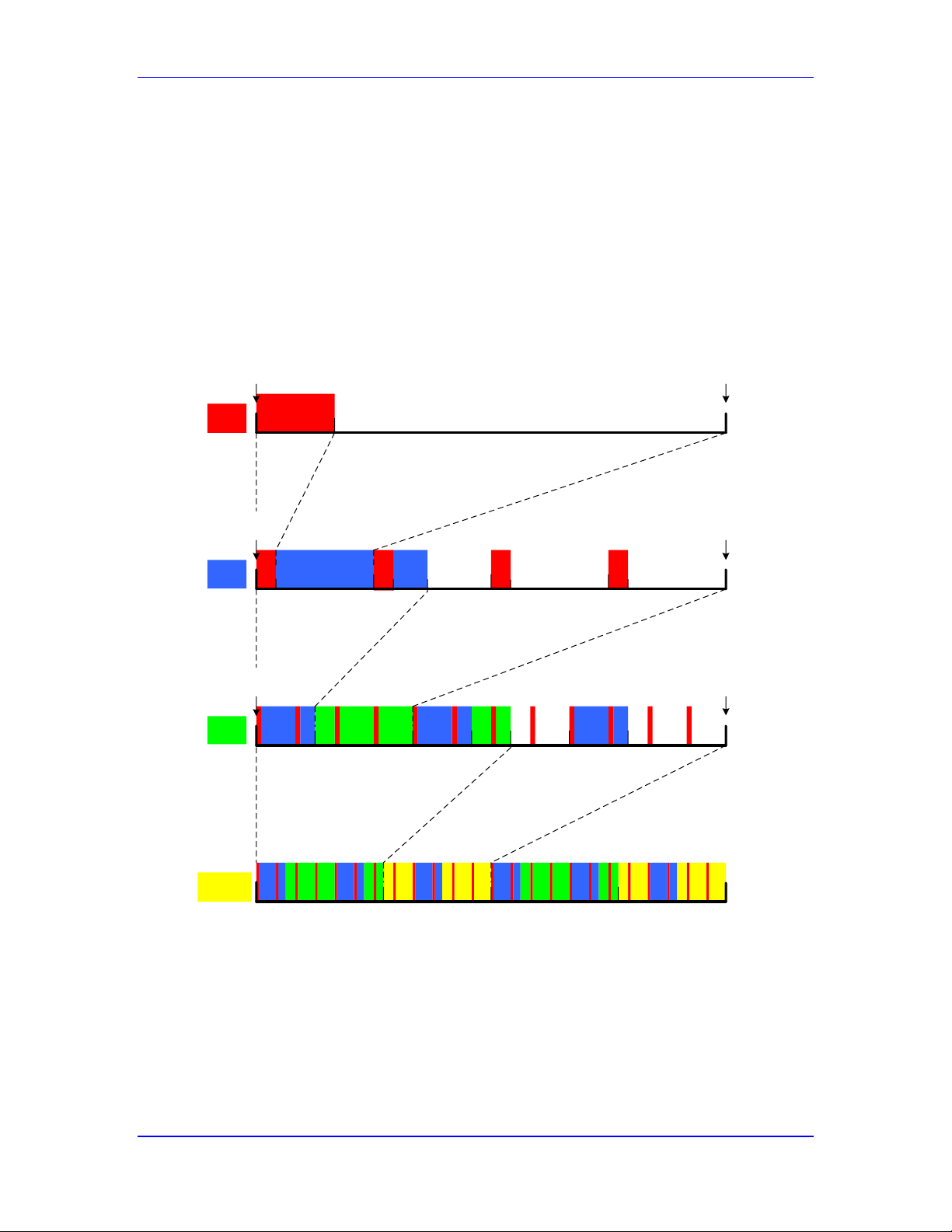
Power PMAC User’s Manual
Power PMAC System Configuration 74
Multi-Tasking Example
The following time-line drawing provides an example of how a single-core Power PMAC
processor allocates time for different tasks. The top line shows one phase cycle, with the phase
tasks highlighted in red at the beginning of the cycle, immediately following the interrupt. The
second line shows a servo cycle, with the servo tasks highlighted in blue occurring after the
higher-priority phase tasks have finished.
The third line shows a real-time interrupt cycle, with the RTI tasks highlighted in green occurring
after the higher-priority phase and servo tasks have finished. The last line shows a background
cycle (which is not a fixed-time cycle like the above cycles are), with the background tasks
highlighted in yellow occurring when all the interrupt tasks have finished.
Phase
Interrupt
Phase
Interrupt
Servo
Interrupt
Servo
Interrupt
RTI
RTI
#1 #3
#4#2
Phase Update
(Lower Priority Tasks)
(Ph)
(Ph)
(Ph) (Ph)ECT Interp
Comp
(Lower Priority)
(Lower Priority Tasks)
(Lower Priority Tasks)
Phase
Cycle
Servo
Cycle
RTI
Cycle
Servo Update
(Ph/Srv) (Ph/Srv) (Ph/Srv)
S. U.
Loops
&1
&2
&3
Motion Prog
RTPLC
RTCPLC
(Background)
(Background)
Background
Cycle
(Interrupt Tasks)
(Interrupt Tasks)
BGPLC BGCPLCs
Sleep for GPOS Apps
Example Power PMAC Multi-Tasking Time Line (Single Core)
Multiple-Core Task Assignments
Power PMACs with multiple CPU cores can run multiple tasks simultaneously on different cores,
substantially increasing the total computational capability of the processor.
In a dual-core CPU, the core executing the interrupt tasks is idle during the periods where a
single-core CPU would be executing background tasks (yellow in the above example). The other
core will be executing background tasks concurrently.
Page 75
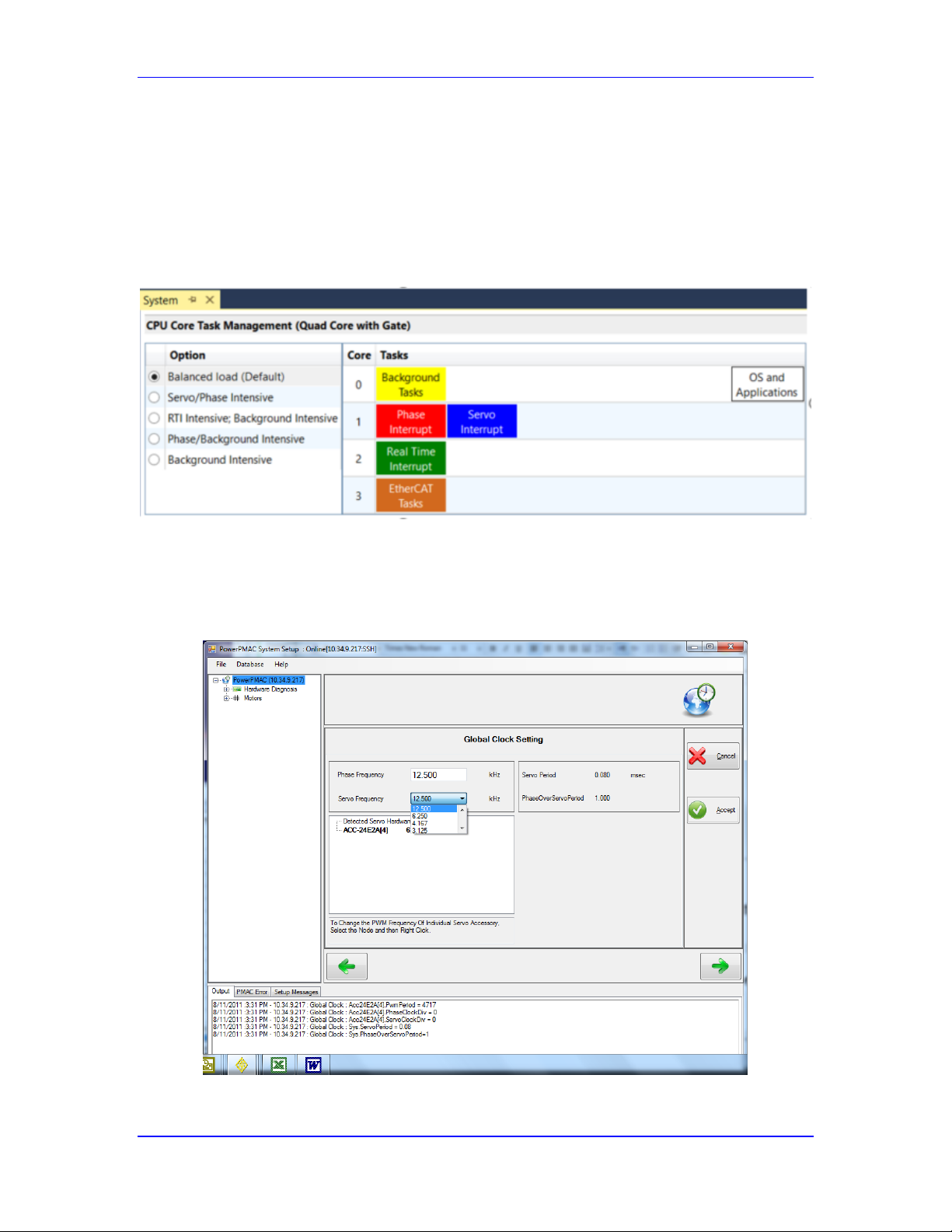
Power PMAC User’s Manual
Power PMAC System Configuration 75
Power PMACs with Quad Core ARM CPUs (LS1043A) permit the user to change the task
assignments from the default configuration through the IDE. Note, however, that the default
configuration is appropriate for the large majority of applications, so the assignments should be
changed only if the default is found to be not appropriate. See the section “Task Priority Duty
Cycles” below for information on analyzing these cases.
The IDE control for assigning tasks to cores is shown below. If the configuration is changed, a
full reboot or power cycling is required to implement the change.
Using the IDE to Set Phase and Servo Clock Frequencies
It is possible to use the IDE to set the phase and servo clock frequencies without the need to
understand the underlying mechanisms that control the frequencies. From the top menu of the
IDE, select “Tools”, then “System Setup”. A window like the following will appear:
IDE System Setup Global Clock Setting Control
Page 76
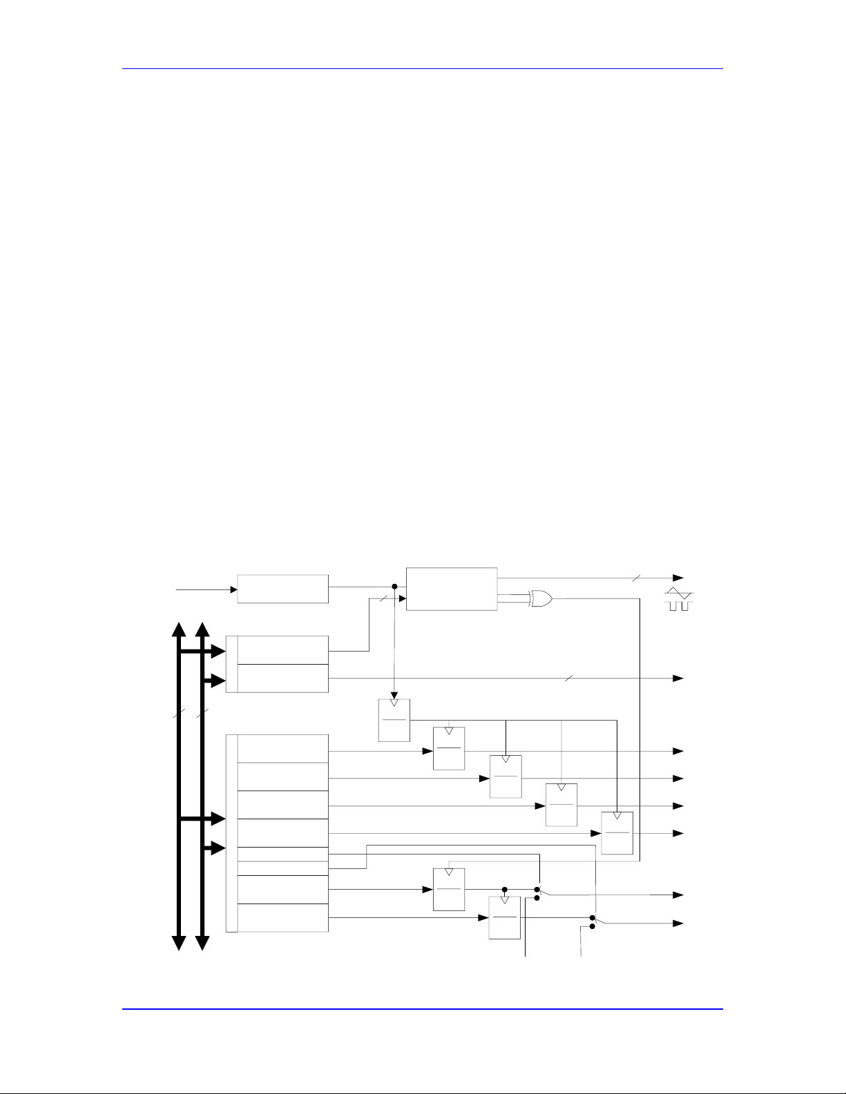
Power PMAC User’s Manual
Power PMAC System Configuration 76
In this window, you can enter your desired phase-clock frequency directly in kilohertz (kHz). For
the servo-clock frequency, which must be derived from the phase-clock frequency, you must
choose from the pick list of possible frequencies. The PWM frequencies of hardware that can
generate pulse-width-modulated signals can also be selected from a pick list by right-clicking on
the hardware name. Once you have entered the settings you want, click on the “Accept” button on
the right to load the appropriate settings into the Power PMAC.
The following sections explain how to make these settings manually and directly, both for
understanding and to permit other avenues for specifying these settings.
Setting Phase and Servo Clock Frequencies in PMAC2-Style ICs
In a PMAC2-style Servo or MACRO IC, the internally generated phase and servo clock
frequencies are determined by the setting of three saved setup elements for the IC:
Gaten[i].PwmPeriod
Gaten[i].PhaseClockDiv
Gaten[i].ServoClockDiv
In this description, n is 1 for a DSPGATE1 Servo IC, or 2 for a DSPGATE2 MACRO IC.
The following figure shows the block diagram for the circuits that generate these clock signals, as
well as the “hardware clock” signals in a PMAC2-style IC.
PMAC2 Gate Array IC Clock Control
24
Data
1
3
1
2
n
1
2
n
1
2
n
1
2
n
PWM
Up/Down
Counter
6
Address
1
2
n
1
2
n
x6 Phase
Locked Loop
16
External
Phase
External
Servo
n = 0 - 15
n = 0 - 15
n = 0 - 7
n = 0 - 7
n = 0 - 7
n = 0 - 7
PHASE
SERVO
ADCCLK
DACCLK
PFMCLK
SLCK
DT / PW
PWM COUNT
16
8
40 MHz
Phase
Clock Control
Encoder Sample
Clock Control
PFM
Clock Control
DAC
Clock Control
ADC
Clock Control
Servo
Clock Control
Int/Ext Phase
Int/Ext Servo
PWM Max
Count
PWM Dead Time/
PFM Pulse Width
20 MHz
Max Phase
120 MHz
SIGN
DIR
Page 77

Power PMAC User’s Manual
Power PMAC System Configuration 77
Gaten[i].PwmPeriod: MaxPhase Clock Frequency Control
As the name suggests, Gaten[i].PwmPeriod sets the period of the PWM cycle in the IC, to a time
proportional to its value. The frequency is, of course, inversely proportional to the period. But it
also sets the period of the internal “MaxPhase” clock signal, which is always ½ of the PWM
cycle period – so its frequency is twice the PWM frequency. Even if you are not using PWM
signals from the IC, the setting of this element is important.
To set Gaten[i].PwmPeriod for a desired “MaxPhase” clock frequency, the following formula
can be used:
1
)(*2
)(8.964,117
].[
kHzeqMaxPhaseFr
kHz
PwmPeriodiGaten
Gaten[i].PhaseClockDiv: Phase Clock Frequency Control
From the internal “MaxPhase” clock signal, the phase clock signal is generated with a frequency
divider circuit that is controlled by Gaten[i].PhaseClockDiv. The phase clock frequency is equal
to the “MaxPhase” clock frequency divided by (Gaten[i].PhaseClockDiv + 1).
The equation for Gaten[i].PhaseClockDiv is:
1
)(
)(
].[
kHzPhaseFreq
kHzeqMaxPhaseFr
DivPhaseClockiGaten
At the default value of 0 (divide by 1) and the default MaxPhase frequency of 9.04 kHz, this sets
a phase clock frequency of 9.04 kHz (110 μsec period).
Gaten[i].ServoClockDiv: Servo Clock Frequency Control
From the phase clock signal, the servo clock signal is generated with a frequency divider circuit
that is controlled by Gaten[i].ServoClockDiv. The servo clock frequency is equal to the phase
clock frequency divided by (Gaten[i].ServoClockDiv + 1).
The equation for Gaten[i].ServoClockDiv is:
1
)(
)(
].[
kHzServoFreq
kHzPhaseFreq
DivServoClockiGaten
At the default value of 3 (divide by 4) and the default phase clock frequency of 9.04 kHz, this sets
a servo clock frequency of 2.26 kHz (442 μsec period).
The following diagram shows the relationship between the PWM counter, whose
period/frequency is set by the Gaten[i].PwmPeriod parameter, the resulting MaxPhase clock
signal, and the phase and servo clock signals that are derived from MaxPhase.
Page 78
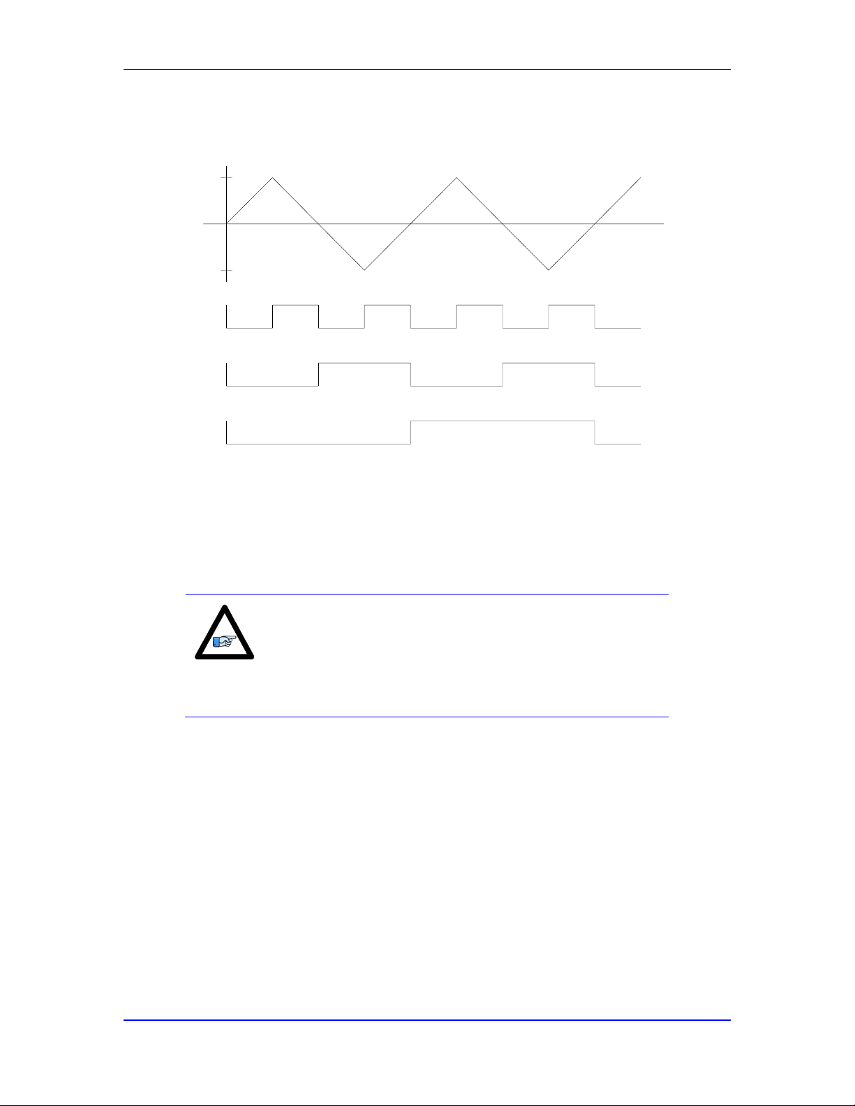
Power PMAC User’s Manual
Power PMAC System Configuration 78
PMAC2 Clock Signal Example
PWM
Counter
+Pwm
Period
-Pwm
Period
t
Max
Phase
Phase
Servo
Setting Phase and Servo Clock Frequencies in PMAC3-Style ICs
In a PMAC3-style “DSPGATE3” machine-interface IC, the internally generated phase and servo
clock frequencies are determined by the setting of two saved setup elements for the IC:
Gate3[i].PhaseFreq
Gate3[i].ServoClockDiv
Note
Sys.WpKey must be set to $AAAAAAAA in order to enable
changes to Gate3[i] setup elements. While the IDE does this
automatically for its interactive controls that set these elements,
if you set them directly through commands, you must explicitly
set this key value.
The following figure shows the block diagram for the circuits that generate these clock signals, as
well as the “hardware clock” signals in a PMAC3-style IC.
Page 79
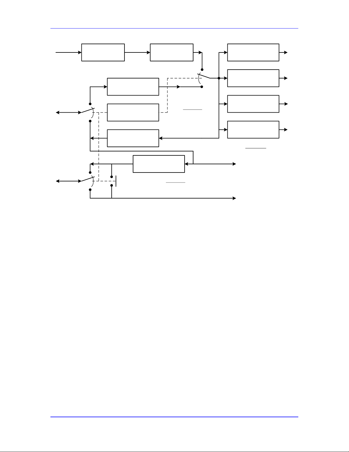
Power PMAC User’s Manual
Power PMAC System Configuration 79
x12 Phase
Locked Loop
Gate3[i].
PhaseFreq
Gate3[i].Chan[0].
PwmFreqMult
Gate3[i].
PhaseClockDiv
Gate3[i].Chan[1].
PwmFreqMult
Gate3[i].Chan[2].
PwmFreqMult
Gate3[i].Chan[3].
PwmFreqMult
Gate3[i].
PhaseServoDir
Gate3[i].
PhaseClockMult
25 MHz
300 MHz
External
Phase
Clock
Gate3[i].
ServoClockDiv
PSD Bit 0 = 1
PSD Bit 0 = 0
PSD Bit 0 = 1
PSD Bit 0 = 0
PSD Bit 1=1
PSD Bit 1=0
External
Servo
Clock
<- PSD Bit 1 = 0
-> PSD Bit 1 = 1
To IC circuits
To IC circuits
Internal
Phase
Clock
Internal
Servo
Clock
'
2
1
PhasePWM
f
PFM
f
PCD
PhaseExt
Phase
f
f
2
'
'
"
2
Phase
PCM
Phase
f
f
1
SCD
f
f
PhaseInt
Servo
0PWM
f
1PWM
f
2PWM
f
3PWM
f
PMAC3 IC Clock Generation Circuitry
Gate3[i].PhaseFreq: Phase Clock Frequency Control
In the DSPGATE3 IC, the phase clock frequency is generated directly from a 300 MHz clock
signal as controlled by the saved setup element Gate3[i].PhaseFreq. This element is a floatingpoint value, expressed directly in Hertz (not kHz!). The default value of 9035.69 sets a frequency
of approximately 9.04 kHz.
If the IC is generating its own phase clock, it is possible for it to output a phase clock signal to the
system that is 2, 4, or 8 times the frequency that it uses internally, as controlled by saved setup
element Gate3[i].PhaseClockMult. The internal frequency is multiplied by a value of
(2^Gate3[i].PhaseClockMult) to obtain the output frequency. At the default value of 0, the
output frequency is the same as the internal frequency, and this should only be changed for
specialized systems, generally those that require a very wide range of PWM frequencies from
different ICs.
If the IC is accepting an external phase clock, it is possible for it to divide down this frequency
for internal use by a factor of 2, 4, or 8, as controlled by saved setup element
Gate3[i].PhaseClockDiv. The external frequency is divided by a value of
(2^Gate3[i].PhaseClockDiv) to obtain the internal frequency. At the default value of 0, the
internal frequency is the same as the input frequency, and this should only be changed for
specialized systems, generally those that require a very wide range of PWM frequencies from
different ICs.
Note that in the DSPGATE3 IC, the channel PWM frequencies are derived from the phase clock
frequency, whereas in the older PMAC2-style ICs, the phase clock frequency is derived from the
Page 80

Power PMAC User’s Manual
Power PMAC System Configuration 80
(common) PWM frequency. In the DSPGATE3 IC, a channel’s PWM frequency is determined by
Gate3[i].Chan[j].PwmFreqMult, and can range from 0.5 to 3.5 times the phase clock frequency.
Gate3[i].ServoClockDiv: Servo Clock Frequency Control
From the phase clock signal, the servo clock signal is generated with a frequency divider circuit
that is controlled by Gate3[i].ServoClockDiv. The servo clock frequency is equal to the phase
clock frequency divided by (Gate3[i].ServoClockDiv + 1).
The equation for Gate3[i].ServoClockDiv is:
1
)(
)(
].[3
kHzServoFreq
kHzPhaseFreq
DivServoClockiGate
At the default value of 3 (divide by 4) and the default phase clock frequency of 9.04 kHz, this sets
a servo clock frequency of 2.26 kHz (442 μsec period).
Clock-Related Software Settings
There are several software setup elements related to the phase and servo clock settings.
Sys.PhaseCycleExt: Phase Cycle Extension
In the Power PMAC, it is possible to skip hardware phase clock cycles between consecutive
executions of the phase update software. Power PMAC will execute the phase update software –
mainly phase commutation and current-loop closure – every (Sys.PhaseCycleExt + 1) phase
clock cycles. The default value of Sys.PhaseCycleExt is 0, so normally Power PMAC executes
the phase update software every cycle of the hardware phase clock.
If the Power PMAC is closing the current loop for direct PWM control over the MACRO ring, it
is desirable to have two hardware ring update cycles (which occur at the hardware phase clock
frequency) per software phase update. This eliminates one ring cycle of delay in the current loop,
which permits higher gains and performance. To do this, the phase clock frequency would be set
twice as high as the desired current-loop closure frequency (e.g. 18 kHz vs. 9 kHz), and
Sys.PhaseCycleExt would be set to 1.
Sys.PhaseOverServoPeriod: Ratio of Phase to Servo Period
If a Power PMAC motor has been set up to close its servo loop under the phase interrupt by
setting bit 3 (value 8) of Motor[x].PhaseCtrl to 1, it must compute a new desired position every
software phase update with a “sub-interpolation” algorithm from the desired positions computed
in the servo update. To do this, it must know what fraction of the servo update period the phase
update period is. Global saved setup element Sys.PhaseOverServoPeriod must be set to specify
this properly. For example, at the default setting where the phase update frequency is 4 times the
servo update frequency, Sys.PhaseOverServoPeriod would be set to 0.25 (1/4). If no motor is
closing its servo loop under the phase interrupt, this parameter is not used.
Sys.ServoPeriod: Servo Update Time Parameter
Once the period/frequency of the phase and servo clock signals is set, the user must tell the Power
PMAC what the scaled time period of the servo clock signal is. This numeric value is used in the
trajectory interpolation algorithms as the (nominal) time update value between consecutive servo
cycles. Saved setup element Sys.ServoPeriod must contain this value in units of milliseconds.
Unless the processor is generating its own interrupts internally (Sys.CpuTimerIntr = 1), this
Page 81

Power PMAC User’s Manual
Power PMAC System Configuration 81
parameter does not control the servo update period, it merely notifies the interpolation software
what this period is. The default value of Sys.ServoPeriod matches the default settings for the
servo update period in the Gaten[i] data structures.
Motor[x].Stime: Motor Servo-Loop Closure Extension
It is possible to extend the time between consecutive servo loop closures for an individual motor
by setting Motor[x].Stime to a value greater than 0. The motor skips this many servo interrupt
periods between consecutive loop closures, so closes its loop every (Motor[x].Stime + 1) servo
interrupt periods. This feature is valuable for actuators with very slow dynamics. This is
discussed in more detail in the Setting Up the Servo Loop chapter of the User’s Manual.
Sys.RtIntPeriod: Real-Time Interrupt Period
The real-time interrupt (RTI) is the next lower priority after the servo interrupt. The period is an
integer multiple of the servo period – it executes every (Sys.RtIntPeriod + 1) servo periods. At
the default setting, it occurs every third servo period. The main tasks performed in the real-time
interrupt are motion program calculations and foreground PLC (script and C) program
calculations. It also decrements the watchdog timer counter each RTI period, and this must
happen more than 40 times per second to avoid a watchdog timer trip.
Sys.MotorsPerRtInt: Number of Motors Checked per RTI
By default, Power PMAC will perform a safety and status update for each active motor every
real-time interrupt, checking for issues such as overtravel limits, amplifier faults, encoder loss,
and integrated current limits. This checking can often take 0.5 microseconds or more per motor
per RTI.
In applications with very high RTI frequencies, typically for very high move block rates, this
frequency of checking is not needed and can consume a noticeable percentage of CPU time.
Setting Sys.MotorsPerRtInt (new in V1.6 firmware, released 1st quarter 2014) to a value greater
than 0 means that only the specified number of motors will be checked each RTI. This parameter
provides the user with additional flexibility in allocating CPU time in demanding applications.
Setting the Phase and Servo Clock Period in the CPU
If there are no DSPGATEn ICs in the Power PMAC system to generate system phase and servo
clocks to interrupt the processor, the processor can be set up to generate its own interrupt
internally. This is done by setting saved setup element Sys.CpuTimerIntr to 1. (At the default
value of 0, the processor is expecting to receive external clock signals from an IC.) In this mode,
Sys.ServoPeriod actually sets the period/frequency of the phase and servo updates (which are the
same), rather than just reporting a value to the interpolation routines.
This mode of operation is used when the Power PMAC is commanding servo drives over a
network such as EtherCAT and does not need any local ICs, or for software simulation purposes
when only a CPU is present. Note that the CPU cannot output physical phase and servo clock
signals in this mode, so it could not be kept synchronized with any of these local ICs.
Page 82
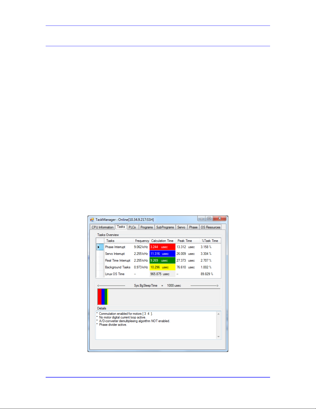
Power PMAC User’s Manual
Power PMAC System Configuration 82
Diagnosing Issues with Clock Settings
Power PMAC provides numerous status indicators to permit you to optimize and troubleshoot
your clock settings.
Missing Clock Signals
At power-up/reset, if the Power PMAC is expecting to receive hardware phase and servo clock
signals (that is, the saved value of Sys.CpuTimerIntr is 0) but does not receive them, it will set
global status bit Sys.NoClocks to 1. When this occurs, the processor continues to operate, but no
motors may be enabled. This setting allows the user to reconfigure the system for the proper
hardware or software clock source, save these settings, and reset the system to continue with
system development.
If Power PMAC detects valid clock signals at power-up/reset, but loses them subsequently, the
watchdog timer will trip, shutting down operation of the system. If saved setup element
Sys.BgWDTReset is set well, a “soft” trip will occur, leaving the processor running, but forcing
all interface hardware into its reset state. If such a soft trip does not occur, the hardware watchdog
timer circuitry will force a “hard” trip, completely shutting down the processor as well as forcing
all interface hardware into its reset state. For more details on the watchdog timer, refer to the
User’s Manual chapter Making Your Power PMAC Application Safe.
Task Priority Duty Cycles
Power PMAC provides numerous status elements for the user to understand how much processor
time is spent at each priority level. This information is valuable in optimizing the clock
frequencies for a given application. The IDE’s “task manager” display summarizes this
information well. A sample display for a single-core CPU is shown below:
Power PMAC IDE Single-Core CPU Task Time Overview Display
Page 83
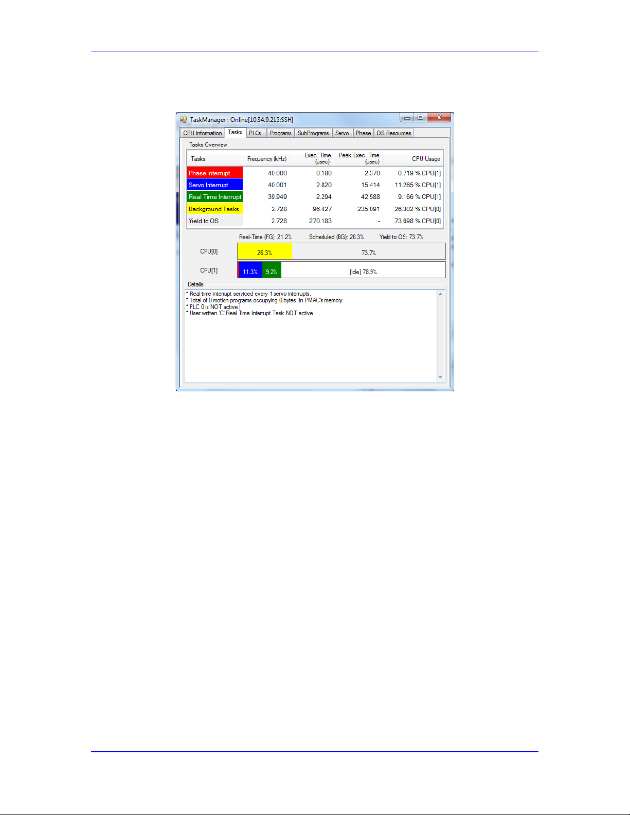
Power PMAC User’s Manual
Power PMAC System Configuration 83
A sample display for a dual-core CPU is shown in the next figure. It shows the time usage of each
core separately.
Power PMAC IDE Dual-Core CPU Task Time Overview Display
Note that the time status elements used for these displays, and detailed below, are only directly
accessible from the Script environment, as they actually implement function calls to calculate the
scaled values.
Phase Task Statistics
The following status data structure elements can be used to understand the processor loading
under the phase-clock interrupt:
Sys.PhaseDeltaTime Time between start of last two phase cycles (µsec)
Sys.PhaseTime Time to complete tasks in last phase cycle (µsec)
Sys.FltrPhaseTime Filtered average time in recent phase cycles (µsec)
Sys.MinPhaseTime Lowest time to complete tasks in a phase cycle (µsec)
Sys.MaxPhaseTime Highest time to complete tasks in a phase cycle (µsec)
Sys.PhaseErrorCtr # of phase cycles tasks failed to complete in time
The user can set the Sys.MinPhaseTime and Sys.MaxPhaseTime elements to 0.0 to “reset”
them, and Power PMAC will restart its evaluation of the lowest and highest times, respectively,
from this point. This is useful when a change in configuration is made.
Any incrementing of the Sys.PhaseErrorCtr value should be considered a serious problem that
requires correction.
Page 84

Power PMAC User’s Manual
Power PMAC System Configuration 84
Servo Task Statistics
The following status data structure elements can be used to understand the processor loading
under the servo-clock interrupt:
Sys.ServoDeltaTime Time between start of last two servo cycles (µsec)
Sys.ServoTime Time to complete tasks in last servo cycle (µsec)
Sys.FltrServoTime Filtered average time in recent servo cycles (µsec)
Sys.MinServoTime Lowest time to complete tasks in a servo cycle (µsec)
Sys.MaxServoTime Highest time to complete tasks in a servo cycle (µsec)
Sys.ServoBusyCtr # of servo cycles tasks failed to complete in time
Sys.ServoErrorCtr # of servo cycles skipped entirely due to task overrun
The user can set the Sys.MinServoTime and Sys.MaxServoTime elements to 0.0 to “reset”
them, and Power PMAC will restart its evaluation of the lowest and highest times, respectively,
from this point. This is useful when a change in configuration is made.
If the servo tasks are interrupted by the phase clock before they are finished, the time elapsed
measured for the servo tasks, which is simply the difference between the times when they started
and when they ended, includes any intervening higher-priority phase tasks. For details of how to
derive the actual servo task time, refer to the individual element descriptions in the Software
Reference Manual.
Any incrementing of the Sys.ServoBusyCtr value, or especially the Sys.ServoErrorCtr value,
should be considered a serious problem that requires correction.
Real-Time Interrupt Task Statistics
The following status data structure elements can be used to understand the processor loading
under the real-time interrupt:
Sys.RtIntDeltaTime Time between start of last two RTI cycles (µsec)
Sys.RtIntTime Time to complete tasks in last RTI cycle (µsec)
Sys.FltrRtIntTime Filtered average time in recent RTI cycles (µsec)
Sys.MinRtIntTime Lowest time to complete tasks in an RTI cycle (µsec)
Sys.MaxRtIntTime Highest time to complete tasks in an RTI cycle (µsec)
Sys.RtIntBusyCtr # of RTI cycles tasks failed to complete in time
Sys.RtIntErrorCtr # of RTI cycles skipped entirely due to task overrun
The user can set the Sys.MinRtIntTime and Sys.MaxRtIntTime elements to 0.0 to “reset” them,
and Power PMAC will restart its evaluation of the lowest and highest times, respectively, from
this point. This is useful when a change in configuration is made.
Note
Because of the way the user’s real-time interrupt C PLC
(rticplc) program is called, its execution time is not included in
these time calculations.
If the real-time interrupt tasks are interrupted by the phase or servo clock before they are finished,
the time elapsed measured for the real-time interrupt tasks, which is simply the difference
Page 85

Power PMAC User’s Manual
Power PMAC System Configuration 85
between the times when they started and when they ended, includes any intervening higherpriority phase or servo tasks. For details of how to derive the actual RTI task time, refer to the
individual element descriptions in the Software Reference Manual.
Incrementing of the Sys.RtIntBusyCtr value, or even the Sys.RtIntErrorCtr value, especially if
only occasional, is not necessarily a problem, but it may be important to understand that this is
happening.
Background Task Statistics
The following status data structure elements can be used to understand the processor loading in
the scheduled background task cycle:
Sys.BgDeltaTime Time between start of last two BG cycles (µsec)
Sys.BgTime Time to complete tasks in last BG cycle (µsec)
Sys.FltrBgTime Filtered average time in recent BG cycles (µsec)
Sys.MinBgTime Lowest time to complete tasks in a BG cycle (µsec)
Sys.MaxBgTime Highest time to complete tasks in a BG cycle (µsec)
The user can set the Sys.MinBgTime and Sys.MaxBgTime elements to 0.0 to “reset” them, and
Power PMAC will restart its evaluation of the lowest and highest times, respectively, from this
point. This is useful when a change in configuration is made.
In the standard single-core CPUs, if the scheduled background tasks are interrupted by the phase,
servo, or RTI clock before they are finished, the time elapsed measured for the background tasks,
which is simply the difference between the time when they started and when they ended, includes
any intervening higher-priority phase, servo, or RTI tasks.
In a multi-core CPU, the background tasks are running on a separate core, so are not interrupted
by foreground tasks. In this case, the time elapsed from start to finish is the time actually spent
computing these tasks.
The background cycle does not have a fixed period. After a background cycle’s tasks complete,
the background execution thread “sleeps” for the time set by Sys.BgSleepTime (1.0 millisecond
by default) before it will look to start the next cycle. This interval provides independent C
applications with time to execute. Of course, all interrupt-based tasks will pre-empt any
background tasks.
Interrupt Response Latency
The typical delay between the hardware interrupt signal and the start of interrupt software tasks is
about 1 microsecond. However, there will be variations in this delay from cycle to cycle, and at
very high phase and servo update rates, it is possible for these variations to impact performance.
The time from the start of interrupt software tasks in one phase cycle to the start of these tasks in
the next phase cycle can be found in status element Sys.PhaseDeltaTime. The longest time found
is stored in Sys.MaxPhaseDeltaTime; the shortest time found is stored in
Sys.MinPhaseDeltaTime. (The user can set these max and min elements to 0.0 to “reset” them.)
If there is an unusually long latency in one cycle, Sys.PhaseDeltaTime for that cycle will be
large. If the following cycle has a typical delay, Sys.PhaseDeltaTime for this next cycle will be
small. A good estimate of worst case latency (WCL) can be made by calculating:
Page 86

Power PMAC User’s Manual
Power PMAC System Configuration 86
1
2
..
ltaTimeMinPhaseDeSysltaTimeMaxPhaseDeSys
WCL
In this equation, the variation in latency is determined by subtracting the “min” value from the
“max” value and dividing by 2. This variation is then added to the typical latency of 1 μsec.
In a single-core CPU, the primary cause of intermittent high latency is heavy Ethernet
communications, as there are certain tasks in the communications that cannot be interrupted.
These can cause occasional latencies of 10 μsec or more. In a dual-core CPU, Ethernet
communications is handled on a different core from the interrupt tasks, so this is not an issue.
In a dual-core CPU, the primary cause of intermittent high latency is arbitration of shared
resources between cores, such as the external memory bus. These can cause occasional latencies
of 3 to 4 μsec.
If the worst case latency causes the command output value of a phase or servo task to be
computed after it should be sent to the output devices, this can cause a “glitch” in the control
effort, which may not be tolerable in the application.
Page 87

Power PMAC User’s Manual
Setting Up the MACRO Ring 87
SETTING UP THE MACRO RING
Many Power PMAC applications will utilize the MACRO ring for communications between
controllers, amplifiers, and I/O modules. Setup of the MACRO ring requires hardware and
software configuration summarized in this section. Individual MACRO devices have
documentation explaining details particular to the individual devices. Many of the instructions in
this chapter relating to the software setup of the encoder conversion table and motors to use the
MACRO ring are also covered in chapters for those features, but the uses of the MACRO ring is
dispersed throughout those chapters.
If your Power PMAC application does not utilize the MACRO ring, this chapter can be skipped.
MACRO Ring Overview
MACRO is a real-time motion and machine control network in a ring configuration. Developed
by Delta Tau Data Systems, it is an open protocol with many vendors providing compatible
components. It is built around 100 megabit-per-second Ethernet technology (125 Mbit/sec with
error correction bits) for high-speed transfers around the ring, minimizing transport delays. Most
commonly used is fiber-optic transmission between stations on the ring, which provides complete
noise immunity and the capability for long transmission between stations.
MACRO is a master/slave network. Power PMAC is most commonly used as a master on the
ring, sending commands to slave servo drives, I/O modules, and other peripherals on the ring, and
receiving feedback values from them. However, it is possible to configure Power PMAC as a
slave device on the ring, and for its motors to be set up to accept cyclic servo commands over the
ring. This permits a single Power PMAC (the master) to compute all of the coordinated tasks, but
to distribute the individual motor tasks such as servo-loop closure and motor commutation, and
the hardware, across the ring.
Power PMAC MACRO Interfaces
There are several hardware interfaces to the MACRO ring for Power PMAC configurations. With
each interface, the Power PMAC can be configured as a master or a slave on the ring, although it
is much more common to configure it as a master.
ACC-5E MACRO Interface for UMAC
In a Power UMAC rack, the ACC-5E can be used for the MACRO interface. It can be configured
with one or two PMAC2-style “DSPGATE2” MACRO ICs. Each IC supports up to 16 nodes of
communication over the ring, with a separate “master IC” number for each IC. The registers of
each IC can be accessed with the Gate2[i] data structure, or its “alias” of the Acc5E[i] data
structure. Note that the IC’s data structure index i does not need to match the IC’s master number
on the ring, although it will in most applications.
ACC-5E3 MACRO Interface for UMAC
Alternately, the Power UMAC can use the ACC-5E3 for the MACRO interface. This device can
be configured with one or two PMAC3-style “DSPGATE3” MACRO ICs. Each IC supports up to
32 nodes of communication over the ring, in two banks, with a separate “master IC” number for
each bank in the IC. The registers of each IC can be accessed with the Gate3[i] data structure, or
its “alias” of the Acc5E3[i] data structure. Note that an IC with a single data structure index i
supports two separate “master IC” numbers on the ring, so in general, the index and the IC
number will not match.
Page 88

Power PMAC User’s Manual
Setting Up the MACRO Ring 88
ACC-5EP3 MACRO Interface for Etherlite
The Power PMAC Etherlite network controller uses the ACC-5EP3 for the MACRO interface.
This device can be configured with one or two PMAC3-style “DSPGATE3” MACRO ICs. Each
IC supports up to 32 nodes of communication over the ring, in two banks, with a separate “master
IC” number for each bank in the IC. The registers of each IC can be accessed with the Gate3[i]
data structure, or its “alias” of the Acc5EP3[i] data structure. Note that an IC with a single data
structure index i supports two separate “master IC” numbers on the ring, so in general, the index
and the IC number will not match.
MACRO Interface for Power Brick
The optional MACRO interface for the Power Brick line of controllers and integrated
controller/amplifiers uses the same PMAC3-style “DSPGATE3” ICs that are used for the servo
and I/O interfaces within the Brick. It can be configured with one or two of these ICs. Each IC
supports up to 32 nodes of communication over the ring, in two banks, with a separate “master
IC” number for each bank in the IC. The registers of each IC can be accessed with the Gate3[i]
data structure, or its “alias” of the PowerBrick[i] data structure. Note that an IC with a single
data structure index i supports two separate “master IC” numbers on the ring, so in general, the
index and the IC number will not match.
Configuring Master and Slave Devices
The MACRO ring is a “master/slave” network, a configuration that is more deterministic than
“peer-to-peer” networks. This is important for high-performance real-time control. In general, a
controller is a “master” on the ring, and a drive or and I/O device is a slave.
In addition, a MACRO ring can be configured as a “multi-master” network, with each master
device commanding its own slave devices over a common ring. In this setup, one of the master
devices must be configured as the “synchronizing master”, which provides the overall control of
the ring. Other masters on the same ring must be configured as “non-synchronizing” masters. In
the physical connection of the ring, the synchronizing master must be “upstream” of the other
masters. (In a single-master ring, the master device must be configured as a synchronizing
master.)
Note that a single device on a MACRO ring may have multiple MACRO ICs, and each IC must
be configured as to its function on the ring. Only a single IC on the ring may be configured as a
synchronizing master. Other ICs on master devices, even if on the same device as the IC
configured as a synchronizing master, must be set up as non-synchronizing masters.
The function of a MACRO IC on a ring is determined by a saved setup element for the IC. The
exact functionality of this setup element differs based on the IC used.
PMAC2-Style MACRO IC
In a PMAC2-style “DSPGATE2” MACRO IC, the IC’s function on the ring is determined by
saved setup element Gate2[i].MacroMode. (Remember that you can also use the accessory name
for the structure, so you could refer to it as Acc5E[i].MacroMode.) The important bits in this
element are bit 4, bit 5, and bit 7.
Bit 4 (value $10) should be set to 1 if the IC is used as a master on the ring, synchronizing or not.
It should be set to 0 if the IC is used as a slave on the ring.
Page 89

Power PMAC User’s Manual
Setting Up the MACRO Ring 89
Bit 5 (value $20) should be set to 1 if the IC is used as the synchronizing master on the ring (in
which case bit 4 must also be set to 1). It should be set to 0 if the IC is used as a nonsynchronizing master or as a slave.
Bit 7 (value $80) determines whether the IC’s phase clock counter is automatically reset on the
IC’s receipt of the “sync” data packet. This bit should be set to 0 if the IC is used as a
synchronizing master, because its own phase clock will control the entire ring (but setting it to 1
will not hurt operation). The bit should be set to 1 if the IC is used as a non-synchronizing master
or as a slave, in order to keep it in sync with the synchronizing master.
Synchronizing Master IC
The IC used as the ring’s synchronizing master (most commonly Gate2[0]) should have bits 4
and 5 set to 1, and bit 7 set to 0, so Gate2[i].MacroMode should be set to $30 for this IC.
Non-Synchronizing Master IC
An IC used as a non-synchronizing master should have bit 4 set to 1 and bit 5 set to 0. If the IC is
in the same Power PMAC system as the ring’s synchronizing master IC, it receives the ringcontrolling phase clock signal directly, and does not need to use the receipt of the sync packet to
stay synchronized. For such an IC (such as the 2nd MACRO IC on the same ACC-5E as the
synchronizing master, or a MACRO IC on another ACC-5E in the same UMAC rack), bit 7 can
be set to 0, so Gate2[i].MacroMode should be set to $10.
However, if the IC is in a different Power PMAC system from the ring’s synchronizing master
IC, it must use the receipt of the sync packet to stay properly synchronized on the ring. For such
an IC, bit 7 should be set to 1 to maintain this synchronization. In addition, the IC must be able to
accept “broadcast” communications from the synchronizing master, which has a different master
IC number. These broadcast messages are sent on Node 14, so bit 14 (value $4000) of this
element should also be set to 1 to disable the “master-number check” for the Node 14 packet.
This means that Gate2[i].MacroMode should be set to $4090 for this IC (Node 14 masternumber check disable, sync packet receipt lock, and master IC).
Slave IC
An IC used as a slave on the ring should have bits 4 and 5 both set to 0 to disable any master
functionality. Bit 7 should be set to 1 to lock in the IC’s phase clock on receipt of the sync packet.
Bit 14 should be set to 1 to disable the “master-number check” on the Node 14 packet. This
means that Gate2[i].MacroMode should be set to $4080 for this IC (Node 14 master-number
check disable, sync packet receipt lock). This is the default value for the IC.
Element Status Bits
Note that bits 0, 1, 2, 3, and 6 of this element are status bits, and could report non-zero values
when the element is read. Bits 0 – 3, represented in the last hex digit, are error bits that will
seldom report a value of 1 in a properly working ring. Bit 6 reports a value of 1 for an IC that has
received a sync packet since the last time the register has been read, a likely occurrence in a
properly working ring. For example, if Gate2[i].MacroMode has been set to $4090, its value is
likely to be reported as $40D0 when queried on a working ring, or $409F on a non-working ring.
Note that the act of reading this register automatically clears any of these status bits that are set.
PMAC3-Style MACRO IC
In a PMAC3-style “DSPGATE3” MACRO IC, the IC’s function on the ring is determined by
saved setup elements Gate3[i].MacroModeA and Gate3[i].MacroModeB. Note that the
Page 90

Power PMAC User’s Manual
Setting Up the MACRO Ring 90
DSPGATE3 IC acts as a “double IC” on the MACRO ring, with two separate master numbers,
one for bank “A” of MACRO nodes, and one for bank “B”.
(Remember that you can also use the accessory name for the structure, so you could refer to the
elements as Acc5E3[i].MacroModeA and Acc5E3[i]MacroModeB for Power UMAC systems,
or Acc5EP3[i].MacroModeA and Acc5EP3[i].MacroModeB for Power PMAC EtherLite
controllers.) The important bits in this element are bit 12, bit 13, and bit 15.
As key setup variables in the DSPGATE3 IC, these elements are write-protected to prevent
inadvertent changes by unauthorized personnel. In the Script environment, global variable
Sys.WpKey should be set to $AAAAAAAA to permit changes to the values of these elements. In
the C environment, IC variable Gate3[i].WpKey should be set to $AAAAAAAA before each
command that would change the value of these elements in the IC.
Bit 12 (value $1000) should be set to 1 if the IC is used as a master on the ring, synchronizing or
not. It should be set to 0 if the IC is used as a slave on the ring.
Bit 13 (value $2000) should be set to 1 if the IC is used as the synchronizing master on the ring
(in which case bit 12 must also be set to 1). It should be set to 0 if the IC is used as a nonsynchronizing master or as a slave.
Bit 15 (value $8000) determines whether the IC’s phase clock counter is automatically reset on
the IC’s receipt of the “sync” data packet. This bit should be set to 0 if the IC is used as a
synchronizing master, because its own phase clock will control the entire ring (but setting it to 1
will not hurt operation). The bit should be set to 1 if the IC is used as a non-synchronizing master
or as a slave, in order to keep it in sync with the synchronizing master.
Synchronizing Master IC
The IC used as the ring’s synchronizing master (most commonly Gate3[0]) should have bits 12
and 13 set to 1, and bit 15 set to 0, so Gate3[i].MacroModeA and Gate3[i].MacroModeB
should be set to $3000 for this IC.
Non-Synchronizing Master IC
An IC used as a non-synchronizing master should have bit 12 set to 1 and bit 13 set to 0. If the IC
is in the same Power PMAC system as the ring’s synchronizing master IC, it receives the ring-
controlling phase clock signal directly, and does not need to use the receipt of the sync packet to
stay synchronized. For such an IC (such as the 2nd MACRO IC on the same ACC-5E3 or ACC5EP3 as the synchronizing master, or a MACRO IC on another ACC-5E3 in the same UMAC
rack), bit 15 can be set to 0, so Gate3[i].MacroModeA and Gate3[i].MacroModeB should be
set to $1000.
However, if the IC is in a different Power PMAC system from the ring’s synchronizing master
IC, it must use the receipt of the sync packet to stay properly synchronized on the ring. For such
an IC, bit 15 should be set to 1 to maintain this synchronization. In addition, the IC must be able
to accept “broadcast” communications from the synchronizing master, which has a different
master IC number. These broadcast messages are sent on Node 14, so bit 22 (value $400000) of
this element should also be set to 1 to disable the “master-number check” for the Node 14 packet.
This means that Gate3[i].MacroModeA and Gate3[i].MacroModeB should be set to $409000
for this IC (Node 14 master-number check disable, sync packet receipt lock, and master IC).
Page 91

Power PMAC User’s Manual
Setting Up the MACRO Ring 91
Slave IC
An IC used as a slave on the ring, as in a Power Brick drive used as a slave device, should have
bits 12 and 13 both set to 0 to disable any master functionality. Bit 15 should be set to 1 to lock in
the IC’s phase clock on receipt of the sync packet. Bit 23 should be set to 1 to disable the
“master-number check” on the Node 23 packet. This means that Gate3[i].MacroMode should be
set to $808000 for this IC (Node 15 master-number check disable, sync packet receipt lock).
Element Status Bits
Note that bits 8, 9, 10, 11, and 14 of this element are status bits, and could report non-zero values
when the element is read. Bits 8 – 11, represented in the third-to-last hex digit, are error bits that
will seldom report a value of 1 in a properly working ring. Bit 14 reports a value of 1 for an IC
that has received a sync packet since the last time the register has been read, a likely occurrence
in a properly working ring. For example, if Gate3[i].MacroModeA has been set to $409000, its
value is likely to be reported as $40D000 when queried on a working ring, or $409F00 on a nonworking ring. Note that the act of reading this register automatically clears any of these status bits
that are set.
Setting the Ring Frequency
The update frequency for a MACRO ring is set by the phase-clock frequency of the
“synchronizing master” controller IC for the ring. The phase-clock frequency for other ICs on the
ring, both master and slave, should be set a close as possible to this frequency for best
performance, so that the clock does not drift too far away before being re-synchronized.
The synchronizing master IC for the ring should also be the source of the phase-clock signal for
the Power PMAC in which it resides. When a Power PMAC system is re-initialized, it
automatically selects the lowest numbered MACRO IC it finds (with a preference for PMAC3style ICs over PMAC2-style ICs if both are present) as its source for the phase (and servo) clock
signal it uses internally.
The general topic of setting the clock frequencies for a Power PMAC system is covered in the
Power PMAC System Configuration chapter of the User’s Manual. This section covers those
aspects particular to systems with a MACRO ring interface.
PMAC2-Style MACRO IC
In a PMAC2-style “DSPGATE2” MACRO IC, the phase-clock frequency is determined by the
settings of saved setup elements Gate2[i].PwmPeriod, which sets the internal “MaxPhase” clock
frequency, and Gate2[i].PhaseClockDiv, which controls how the phase-clock signal itself is
divided down from MaxPhase.
The required setting for Gate2[i].PwmPeriod to obtain a desired MaxPhase clock frequency is
given by the following equation:
1
)(*2
)(8.964,117
].[2
kHzeqMaxPhaseFr
kHz
PwmPeriodiGate
This is typically rounded down to the next integer if the equation produces a fractional
component.
The frequency of the phase clock signal is given by the following equation:
Page 92

Power PMAC User’s Manual
Setting Up the MACRO Ring 92
1].[2
)(
)(
DivPhaseClockiGate
kHzeqMaxPhaseFr
kHzPhaseFreq
In almost all MACRO systems, it is acceptable to set the phase-clock frequency to the MaxPhase
frequency, so Gate2[i].PhaseClockDiv can be set to 0, and Gate2[i].PwmPeriod can be used
directly to set the phase-clock frequency. In this case, the frequency of any PWM signals
generated by this IC are one-half that of the phase clock. It is rare that the same IC is used to
generate PWM signals, so this is not a constraint in most systems.
For example, to set a phase-clock frequency of 8 kHz, with the internal MaxPhase frequency the
same, Gate2[i].PwmPeriod would be calculated as:
73711
8*2
8.964,117
].[2 PwmPeriodiGate
Gate2[i].PhaseClockDiv would be set to 0 so that the phase-clock frequency is the same as the
MaxPhase clock frequency.
PMAC3-Style MACRO IC
In a PMAC3-style “DSPGATE3” MACRO IC, the phase-clock frequency is determined by the
setting of saved setup element Gate3[i].PhaseFreq, which specifies the frequency directly in
Hertz. To set a phase-clock frequency of 8 kHz, Gate3[i].PhaseFreq would be set to 8000.
As a key setup variable in the DSPGATE3 IC, thiselement is write-protected to prevent
inadvertent changes by unauthorized personnel. In the Script environment, global variable
Sys.WpKey should be set to $AAAAAAAA to permit changes to the value of this element. In the
C environment, IC variable Gate3[i].WpKey should be set to $AAAAAAAA before each
command that would change the value of this element in the IC.
Extending the Phase Software Update
Because data is transmitted serially across the ring between master and slave devices, there are
delays introduced in any feedback loop closed across the ring: one ring-cycle delay for command
data from master to slave, and one ring-cycle delay for feedback data from slave to master. These
time delays can increase the “phase lag” of the feedback loop, reducing or even eliminating the
stability margins of the loop.
If Power PMAC is closing the current loops of motors in “direct PWM” mode, as with Delta
Tau’s Geo MACRO drives, the added ring delays can have a significant impact on the quality of
the resulting performance. In this mode, many users want to increase the hardware ring-cycle
frequency to lessen these delays.
Saved setup element Sys.PhaseCycleExt specifies the number of hardware phase-clock cycles
that are skipped between each phase-clock cycle that causes the software tasks such as
commutation and current-loop closure to execute. At the default value of 0 that is used in almost
all non-MACRO applications, these software tasks are executed every hardware phase-clock
cycle.
If Sys.PhaseCycleExt is set greater than 0, one or more hardware cycles are skipped between
consecutive phase software updates in the Power PMAC. Since the MACRO ring operates on the
Page 93
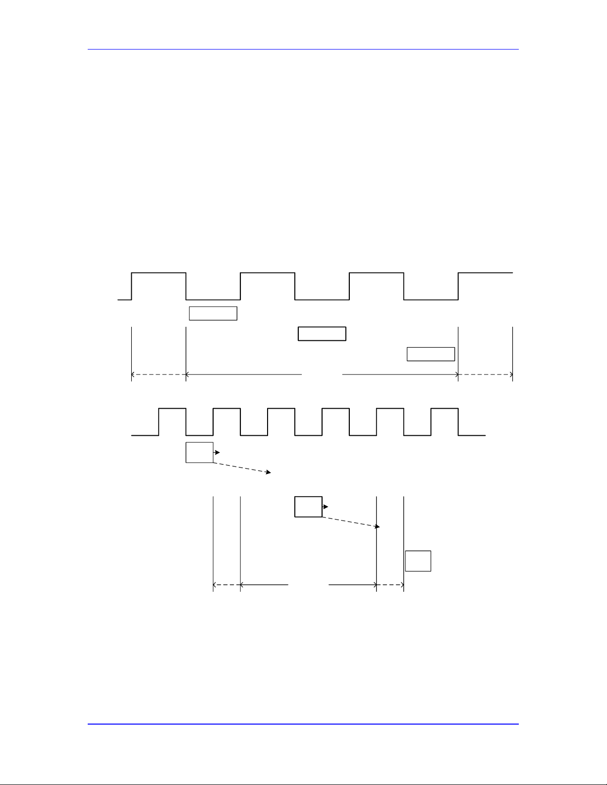
Power PMAC User’s Manual
Setting Up the MACRO Ring 93
hardware phase-clock cycle, it is possible to raise the ring-update frequency without increasing
the software load on the Power PMAC processor, but reduce the ring transport delays to improve
loop performance.
Many MACRO users will set Sys.PhaseCycleExt to 1 so that one hardware cycle is skipped
between consecutive phase software updates. For example, a 20 kHz ring-cycle update frequency
could be used with only a 10 kHz phase-software update rate. This reduces the ring transport
delays from two 100-microsecond periods to two 50-microsecond periods, which can permit
significantly higher performance.
The following timeline diagram shows how the overall data transmission and loop calculations
work with Sys.PhaseCycleExt set to 0 and 1, with the phase-clock frequency doubled when the
setting is 1. Note that the overall loop delays are cut in half in this case, but the frequency of loop
calculations in the master Power PMAC is unchanged.
Slave Input
Transmission
Slave Feedback
Processing
Ring Feedback
Transmission
Master Loop
Calculation
Ring Command
Transmission
Slave Command
Processing
Slave Output
Transmission
Cycle n:
Ring Feedback
Transmission
Master Loop
Calculation
Ring Command
Transmission
Slave Command
Processing
Slave Output
Transmission
Cycle n-1:
Cycle n+1:
Slave Input
Transmission
Slave Feedback
Processing
Ring Feedback
Transmission
Master Loop
Calculation
Ring Command
Transmission
Phase
Clock
Master
Loop
Calc
Total Loop
Delay
Ring
Cmd
Xmit
Slave
Cmd
Proc
Slave
Output
Xmit
Ring
Fdbk
Xmit
Slave
Fdbk
Proc
Slave
Input
Xmit
Master
Loop
Calc
Slave
Fdbk
Proc
Ring
Cmd
Xmit
Slave
Cmd
Proc
Slave
Output
Xmit
Phase
Clock
Cycle n-1:
Cycle n:
Master
Loop
Calc
Cycle n+1:
Ring
Fdbk
Xmit
Ring
Fdbk
Xmit
Slave
Fdbk
Proc
Slave
Input
Xmit
Ring
Cmd
Xmit
Slave
Cmd
Proc
Total Loop
Delay
Slave
Input
Xmit
Slave
Input
Xmit
Slave
Fdbk
Proc
Slave
Fdbk
Proc
Ring
Fdbk
Xmit
Ring
Fdbk
Xmit
(skipped
cycle)
(skipped
cycle)
Ring
Cmd
Xmit
Ring
Cmd
Xmit
Slave
Cmd
Proc
Slave
Cmd
Proc
Slave
Output
Xmit
Slave
Output
Xmit
* *
* *
* For signals with significant
transmission time
Loop closure every ring cycle
Loop closure every second ring cycle
MACRO Loop Delays Without and With Phase Cycle Extension
If Power PMAC is commanding drives over the MACRO ring in torque or velocity mode, as with
most third-party MACRO drives, the fact that the ring is updated every phase-clock cycle, but
new data is only used every servo cycle typically provides sufficient “oversampling” of the ring
(assuming that the phase-clock frequency is higher than the servo-clock frequency) so that this
software extension is not useful.
Page 94
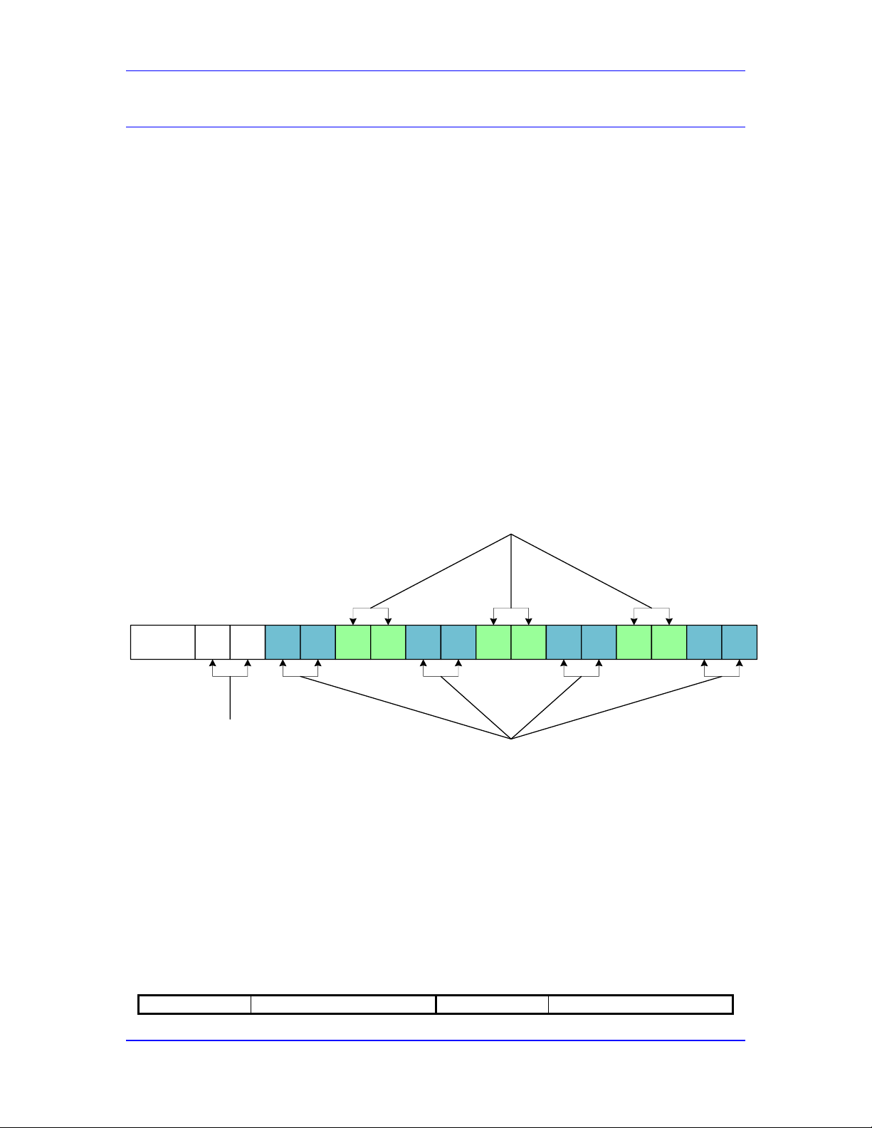
Power PMAC User’s Manual
Setting Up the MACRO Ring 94
Enabling MACRO Nodes
MACRO ring communication occurs through “nodes” on the ring, with each enabled node
transmitting a data packet every ring cycle. An enabled node on a master device will transmit a
command packet every ring cycle, and then expect a feedback packet later in the cycle. An
enabled node on a slave device will expect a command packet every ring cycle, which it will trap
and immediately substitute a feedback packet for return to the master over the ring.
Each node is identified by a 4-bit master number (0 to 15) and a 4-bit slave number (0 to 15).
This means that each master number supports 16 slave numbers. The net 8-bit node number must
match between master and slave devices for communication to take place between the devices.
Node Allocation
For each master IC number, there are 16 nodes, numbered 0 – 15, for which a data packet can be
transmitted each ring cycle. In most MACRO systems, these nodes are organized as follows:
Servo nodes: 0, 1, 4, 5, 8, 9, 12, 13
I/O nodes: 2, 3, 6, 7, 10, 11
Auxiliary nodes: 14, 15
15 14 13 12 11 10 9 8 7 6 5 4 3 2 1 0Node
Auxiliary
Nodes
I/O Nodes
Servo Nodes
MACRO IC Node Allocation
Typical Mapping of MACRO Nodes to Motors
While many different mappings between motors and MACRO nodes in a Power PMAC are
possible, the standard mapping works in numerical order with the lowest-numbered motor
mapped to the lowest-numbered servo node of the first MACRO IC, the next motor mapped to
the next servo node of this IC, and so on until all 8 servo nodes of this IC (or bank of the IC) have
been allocated. The next motor is then mapped to the lowest-numbered servo node of the next
MACRO IC (or next bank of the IC).
For example, with PMAC2-style ICs, the standard mapping for a 20-axis system would be:
Motor
MACRO Node
Motor
MACRO Node
Page 95
Power PMAC User’s Manual
Setting Up the MACRO Ring 95
Motor[1]
Gate2[0].Macro[0]
Motor[11]
Gate2[1].Macro[4]
Motor[2]
Gate2[0].Macro[1]
Motor[12]
Gate2[1].Macro[5]
Motor[3]
Gate2[0].Macro[4]
Motor[13]
Gate2[1].Macro[8]
Motor[4]
Gate2[0].Macro[5]
Motor[14]
Gate2[1].Macro[9]
Motor[5]
Gate2[0].Macro[8]
Motor[15]
Gate2[1].Macro[12]
Motor[6]
Gate2[0].Macro[9]
Motor[16]
Gate2[1].Macro[13]
Motor[7]
Gate2[0].Macro[12]
Motor[17]
Gate2[2].Macro[0]
Motor[8]
Gate2[0].Macro[13]
Motor[18]
Gate2[2].Macro[1]
Motor[9]
Gate2[1].Macro[0]
Motor[19]
Gate2[2].Macro[4]
Motor[10]
Gate2[1].Macro[1]
Motor[20]
Gate2[2].Macro[5]
With PMAC3-style ICs, the standard mapping for a 20-axis system would be:
Motor
MACRO Node
Motor
MACRO Node
Motor[1]
Gate3[0].MacroA[0]
Motor[11]
Gate3[0].MacroB[4]
Motor[2]
Gate3[0].MacroA[1]
Motor[12]
Gate3[0].MacroB[5]
Motor[3]
Gate3[0].MacroA[4]
Motor[13]
Gate3[0].MacroB[8]
Motor[4]
Gate3[0].MacroA[5]
Motor[14]
Gate3[0].MacroB[9]
Motor[5]
Gate3[0].MacroA[8]
Motor[15]
Gate3[0].MacroB[12]
Motor[6]
Gate3[0].MacroA[9]
Motor[16]
Gate3[0].MacroB[13]
Motor[7]
Gate3[0].MacroA[12]
Motor[17]
Gate3[1].MacroA[0]
Motor[8]
Gate3[0].MacroA[13]
Motor[18]
Gate3[1].MacroA[1]
Motor[9]
Gate3[0].MacroB[0]
Motor[19]
Gate3[1].MacroA[4]
Motor[10]
Gate3[0].MacroB[1]
Motor[20]
Gate3[1].MacroA[5]
In both cases, a motor will use the encoder conversion table entry of the same index number (e.g.
Motor[2] will use EncTable[2]).
Enabling Nodes in a PMAC2-Style MACRO IC
In a PMAC2-style “DSPGATE2” MACRO IC, the node enabling function is controlled by saved
setup element Gate2[i].MacroEnable. This 24-bit element is split into three parts. In the first
part, bits 0 – 15, which form the last four hex digits, specify which of Nodes 0 – 15 are enabled,
with bit n specifying for Node n. A value of 1 enables the node; a value of 0 disables the node.
In the second part, bits 16 – 19, which form the second hex digit, specify the node number of the
sync packet. In standard Power PMAC operation, this packet belongs to Node 15, so this hex
digit is set to $F.
In the third part, bits 20 – 23, which form the first hex digit, specify the master number for the IC,
whether the IC is used as a master or a slave device. If it is a slave device, this value specifies the
number of the master to which it responds. While it is possible for separate ICs to share the same
master number, particularly for slave devices, it is essential that no two master devices with the
same master number or no two slave devices with the same master number have any of the same
servo or I/O nodes enabled.
For example, to enable the first six servo nodes (0, 1, 4, 5, 8, and 9), the first three I/O nodes (2,
3, and 6), and the two auxiliary nodes (14 and 15) for master number 1 with sync node 15,
Gate2[i].MacroEnable would be set to $1FC37F.
Hex digit
1 F C 3 7 F
Script Bit #
23
22
21
20
19
18
17
16
15
14
13
12
11
10 9 8 7 6 5 4 3 2 1 0
Bit Value
0 0 0 1 1 1 1 1 1 1 0 0 0 0 1 1 0 1 1 1 1 1 1
1
Page 96
Power PMAC User’s Manual
Setting Up the MACRO Ring 96
Component Master IC Sync Packet # Node Enable Control Bits
Enabling Nodes in a PMAC3-Style MACRO IC
In a PMAC3-style “DSPGATE3” MACRO IC, the node enabling function is controlled by saved
setup elements Gate3[i].MacroEnableA and Gate3[i].MacroEnableB. These 32-bit elements
are split into three active parts. (Note that bits 0 – 7 of these elements are not used.) In the first
part, bits 8 – 23, which form the sixth-to-last through third-to-last hex digits, specify which of
Nodes 0 – 15 are enabled, with bit n specifying for Node n-8. A value of 1 enables the node; a
value of 0 disables the node.
In the second part, bits 24 – 27, which form the second hex digit, specify the node number of the
sync packet. In standard Power PMAC operation, this packet belongs to Node 15, so this hex
digit is set to $F.
In the third part, bits 28 – 31, which form the first hex digit, specify the master number for the IC,
whether the IC is used as a master or a slave device. If it is a slave device, this value specifies the
number of the master to which it responds. While it is possible for separate ICs to share the same
master number, particularly for slave devices, it is essential that no two master devices with the
same master number or no two slave devices with the same master number have any of the same
servo or I/O nodes enabled.
As key setup variables in the DSPGATE3 IC, these elements are write-protected to prevent
inadvertent changes by unauthorized personnel. In the Script environment, global variable
Sys.WpKey should be set to $AAAAAAAA to permit changes to the values of these elements. In
the C environment, IC variable Gate3[i].WpKey should be set to $AAAAAAAA before each
command that would change the value of these elements in the IC.
For example, to enable the first five servo nodes (0, 1, 4, 5, and 8), the first four I/O nodes (2, 3,
6, and 7), and the two auxiliary nodes (14 and 15) for master number 0 with sync node 15,
Gate3[i].MacroEnableA would be set to $0FC1FF00.
0 F C 1 F F 0 0
31
30
29
28
27
26
25
24
23
22
21
20
19
18
17
16
15
14
13
12
11
10 9 8 7 6 5 4 3 2 1 0 0 0 0 0 1 1 1 1 1 1 0 0 0 0 0 1 1 1 1 1 1 1 1 1 - - - - - - - -
Master IC Sync Packet # Node Enable Control Bits
Page 97

Power PMAC User’s Manual
Setting Up the MACRO Ring 97
Ring Check Function
For robust operation of the MACRO ring, it is important to monitor for errors on a continuous
basis. Power PMAC can perform automatic monitoring of the ring for communications errors,
and provide an orderly shutdown if too many errors are detected.
Ring Check Parameters
Saved setup element Macro.TestPeriod sets the evaluation period in real-time interrupt periods
(not ring cycles) over which errors are counted. If it is set to the default value of 0, this evaluation
is not performed. A value of 50 is suggested for performing the evaluation.
Saved setup element Macro.TestMaxErrors specifies the maximum number of errors that can
be detected within a single evaluation period without causing a shutdown. A value of 2 is
suggested for performing the evaluation, which means that the ring would be shut down on a third
error in a given evaluation period.
Saved setup element Macro.TestReqdSynchs specifies the minimum number of the specified
synch packets that must be received within a single evaluation period to avoid a shutdown. A
value of (TestPeriod – 2) is suggested for performing the evaluation, which means the ring
would be shut down if only 2 or more expected sync packets were not received during the test
period.
MACRO Node Register Organization
Each MACRO node in an IC has 8 hardware data registers – 4 output registers and 4 input
registers. In a master device on the MACRO ring (which the Power PMAC usually is), the output
registers of a servo node are “command” registers, and the input registers are “feedback”
registers. In a slave device, the input registers of a servo node are “command” registers, and the
output registers are “feedback” registers.
For the 4 registers in each set, the register index values are 0, 1, 2, and 3. Register 0 has 24 bits (3
bytes) of real data that is transmitted across the ring each cycle. Registers 1, 2, and 3 each have 16
bits (2 bytes) of real data that is transmitted across the ring each cycle.
Standard Use of Registers in a Servo Node
The MACRO protocol describes a standard usage for the command and feedback registers of a
servo node. This usage is described in the following table.
Direction
Register 0
Register 1
Register 2
Register 3
Command
Velocity/Torque/Phase A
Command
(24 bits)
Phase B
Command
(16 bits)
Phase C
Command
(16 bits)
Control Flags
(16 bits)
Feedback
Position Feedback
(24 bits)
Phase A Current
Feedback
(16 bits)
Phase B Current
Feedback
(16 bits)
Status Flags
(16 bits)
Data Elements in a PMAC2-Style MACRO IC
In a PMAC2-style “DSPGATE2” MACRO IC, the MACRO data software elements for accessing
the hardware registers of a node are Gate2[i].Macro[j][k], where i is the IC number (0 to 15), j is
the node number (0 to 15) within the IC, and k is the register number (0 to 3) within the node. In
this IC, each element represents both an output register and an input register. When the element is
Page 98

Power PMAC User’s Manual
Setting Up the MACRO Ring 98
written to, the value is placed in the output register; when the element is read from, the value
returned is from the input register.
Note
Having separate input and output registers at the same address
means that the user cannot read back a value that has been
written to the output register.
All of these data elements are 24-bit values (found in the high 24 bits of Power PMAC’s 32-bit
bus). For registers 1, 2, and 3 of a node, the real 16 bits of data are found in the high 16 bits of the
24-bit element. It is important to realize that many of the automatic functions will access the full
32-bit register, so care must be taken in comparing the 24-bit value in the element with the 32-bit
value used by the automatic function (which will be 256 times larger).
Data Elements in a PMAC3-Style MACRO IC
In a PMAC3-style “DSPGATE3” MACRO IC, the MACRO data software elements for accessing
the hardware output registers of a node are Gate3[i].MacroOutA[j][k] and
Gate3[i].MacroOutB[j][k] for banks A and B, respectively, of the IC, where i is the IC number
(0 to 15), j is the node number (0 to 15) within the IC, and k is the register number (0 to 3) within
the node.
Similarly, in this IC, the MACRO data software elements for accessing the hardware input
registers of a node are Gate3[i].MacroInA[j][k] and Gate3[i].MacroInB[j][k] for banks A and
B, respectively, of the IC. Since the output and input hardware registers are accessed by separate
elements in this IC, it is possible to read back a value written to an output register, which can be
useful for debugging an application.
All of these data elements are 32-bit values. For register 0 of a node, the real 24 bits of data are
found in the high 24 bits of the 32-bit element. For registers 1, 2, and 3 of a node, the real 16 bits
of data are found in the high 16 bits of the 32-bit element.
Processing Position Feedback from the MACRO Ring
As with any other source of position feedback for Power PMAC servo loops, feedback provided
through the MACRO ring, from whatever ultimate source, must be processed through the encoder
conversion table (ECT), before it is used by the servo loop. Often significant processing will
already have occurred at the remote MACRO device before transmission to the Power PMAC.
In almost all cases, the ECT entry will be reading the single value in a MACRO node input
register 0, with real data in bits 8 – 31 of the 32-bit data bus, with the low 5 bits of this data
representing a fractional count value (so the integer count data starts in bit 13).
Encoder Table Entry Method: EncTable[n].type
In virtually all cases, the encoder conversion method will simply be a single-register read, as any
processing of multiple registers will already have been performed at the remote MACRO device.
So EncTable[n].type should be set to 1 to specify this single-register read.
Page 99

Power PMAC User’s Manual
Setting Up the MACRO Ring 99
Encoder Table Entry Source Address: EncTable[n].pEnc
The encoder table entry will read the input (feedback) register for the node as the source of its
data. To specify this, EncTable[n].pEnc for the entry needs to be set to the address of this
register. For a PMAC2-style MACRO IC, the address is specified as Gate2[i].Macro[j][0].a,
where i is the IC number (0 to 15) and j is the node number. For a PMAC3-style MACRO IC, the
address is specified as Gate3[i].MacroInA[j][0].a or Gate3[i].MacroInB[j][0].a.
In most cases, the mapping of encoder table entry numbers to MACRO node numbers is the same
as the mapping of motor numbers to MACRO node numbers explained above (although this is
not required). In this scheme, the motor numbers will match the encoder table entry numbers
number (e.g. Motor[2] will use EncTable[2]).
Note
The EncTable[0] entry is typically not used for standard
feedback. It is not auto-assigned to any hardware address at reinitialization, and few users utilize it for processing motor
feedback sensors.
For example, with PMAC2-style ICs, the standard mapping for a 20-axis system would be:
ECT Pointer Variable
PMAC2 IC Source Address
EncTable[1].pEnc
Gate2[0].Macro[0][0].a
EncTable[2].pEnc
Gate2[0].Macro[1][0].a
EncTable[3].pEnc
Gate2[0].Macro[4][0].a
EncTable[4].pEnc
Gate2[0].Macro[5][0].a
EncTable[5].pEnc
Gate2[0].Macro[8][0].a
EncTable[6].pEnc
Gate2[0].Macro[9][0].a
EncTable[7].pEnc
Gate2[0].Macro[12][0].a
EncTable[8].pEnc
Gate2[0].Macro[13][0].a
EncTable[9].pEnc
Gate2[1].Macro[0][0].a
EncTable[10].pEnc
Gate2[1].Macro[1][0].a
EncTable[11].pEnc
Gate2[1].Macro[4][0].a
EncTable[12].pEnc
Gate2[1].Macro[5][0].a
EncTable[13].pEnc
Gate2[1].Macro[8][0].a
EncTable[14].pEnc
Gate2[1].Macro[9][0].a
EncTable[15].pEnc
Gate2[1].Macro[12][0].a
EncTable[16].pEnc
Gate2[1].Macro[13][0].a
EncTable[17].pEnc
Gate2[2].Macro[0][0].a
EncTable[18].pEnc
Gate2[2].Macro[1][0].a
EncTable[19].pEnc
Gate2[2].Macro[4][0].a
EncTable[20].pEnc
Gate2[2].Macro[5][0].a
Page 100

Power PMAC User’s Manual
Setting Up the MACRO Ring 100
With PMAC3-style ICs, the standard mapping for a 20-axis system would be:
ECT Variable
PMAC3 IC Source Address
EncTable[1].pEnc
Gate3[0].MacroInA[0][0].a
EncTable[2].pEnc
Gate3[0].MacroInA[1][0].a
EncTable[3].pEnc
Gate3[0].MacroInA[4][0].a
EncTable[4].pEnc
Gate3[0].MacroInA[5][0].a
EncTable[5].pEnc
Gate3[0].MacroInA[8][0].a
EncTable[6].pEnc
Gate3[0].MacroInA[9][0].a
EncTable[7].pEnc
Gate3[0].MacroInA[12][0].a
EncTable[8].pEnc
Gate3[0].MacroInA[13][0].a
EncTable[9].pEnc
Gate3[0].MacroInB[0][0].a
EncTable[10].pEnc
Gate3[0].MacroInB[1][0].a
EncTable[11].pEnc
Gate3[0].MacroInB[4][0].a
EncTable[12].pEnc
Gate3[0].MacroInB[5][0].a
EncTable[13].pEnc
Gate3[0].MacroInB[8][0].a
EncTable[14].pEnc
Gate3[0].MacroInB[9][0].a
EncTable[15].pEnc
Gate3[0].MacroInB[12][0].a
EncTable[16].pEnc
Gate3[0].MacroInB[13][0].a
EncTable[17].pEnc
Gate3[1].MacroInA[0][0].a
EncTable[18].pEnc
Gate3[1].MacroInA[1][0].a
EncTable[19].pEnc
Gate3[1].MacroInA[4][0].a
EncTable[20].pEnc
Gate3[1].MacroInA[5][0].a
This type of entry does not use a secondary source, so the setting of EncTable[n].pEnc1 does not
matter. It is fine to leave it at its factory-default setting of Sys.pushm.
Intermediate Processing: EncTable[n].index1, index2
With the real data in the high 24 bits of the 32-bit source register and unknown values in the low
8 bits, some processing is necessary to use only the valid data. EncTable[n].index2 should be set
to 8 to cause an initial “shift-right” of the data by 8 bits to eliminate the low “garbage data”.
The most significant bit of position data in the 24-bit hardware register must end up in the highest
bit of the 32-bit intermediate result in order to support rollover of the source data properly. In the
most common case, there is true position data in all 24 bits of the hardware register. In this case,
EncTable[n].index1 should be set to 8 to cause a secondary “shift-left” of the data by 8 bits to
return the position data to its original position in the 32-bit register (but now with all zeros in the
low 8 bits).
Occasionally, there will not be a full 24 bits of position data in the source register, and this second
operation will need to be slightly different. For example, if the source register contains only 17
bits of position data starting in bit 8 of the 32-bit register (bit 0 of the 24-bit hardware register and
data structure element), after the initial shift-right of 8 bits, the most significant bit of position
data is in bit 16. In order to have this bit end up in bit 31 of the intermediate result, a subsequent
shift-left of 15 bits is required, so EncTable[n].index1 should be set to 15.
Note that in the common case of having 24 bits of true position data, leaving index1 and index2
at their default values of 0 will generally provide acceptable results, with the “noise” from
undetermined data in the low 8 bits not being noticeable in most applications. However, it is
recommended that these elements be set as explained above to minimize the chances of any
problems.
 Loading...