

Page 1

CJ Series
IO-Link Connection Guide
TM
(EtherNet/IP
Host Communications)
OMRON Corporation
Photoelectric Sensor
(E3Z-series IO-Link)
[IO-Link Master Unit]
OMRON Corporation
NX-series IO-Link Master Unit
(NX-ILM[][][])
NX-series Ethernet/IP Coupler Unit
(NX-EIC202)
P666-E1-01
Page 2

About Intellectual Property Rights and Trademarks
Microsoft product screen shots reprinted with permission from Microsoft Corporation.
Windows is a registered trademark of Microsoft Corporation in the USA and other countries.
ODVA and EtherNet/IP
TM
are trademarks of ODVA.
Sysmac is a trademark or registered trademark of OMRON Corporation in Japan and other
countries for OMRON factory automation products.
Company names and product names in this document are t he trademarks or registered
trademarks of their respective companies.
Page 3

Table of Contents
1. Related Manuals ........................................................................................ 1
2. Terms and Definitions ............................................................................... 2
3. Precautions ................................................................................................ 4
4. Overview .................................................................................................... 5
5. Applicable Devices and Device Configuration ....................................... 6
5.1. Applicable Devices ................................................................................ 6
5.2. Device Configuration ............................................................................. 7
6. Communications Settings ........................................................................ 9
6.1. EtherNet/IP Connection Parameters ...................................................... 9
6.2. IO-Link Connection Parameter .............................................................. 9
6.3. Slave Terminal Configuration ................................................................. 9
6.4. Tag Data Link Settings ......................................................................... 10
7. IO-Link Connection Procedure ............................................................... 12
7.1. Work Flow ............................................................................................ 12
7.2. Slave Terminal Setup ........................................................................... 14
7.3. PLC Setup ........................................................................................... 26
7.4. Network Settings for Host Communications ........................................ 36
7.5. IO-Link Communication Status Check ................................................. 48
8. Initialization Method ................................................................................ 59
8.1. Initializing PLC ..................................................................................... 59
8.2. Initializing Slave T erminal .................................................................... 61
8.3. Initializing Photoelectric Sensor ........................................................... 62
9. Revision History ...................................................................................... 63
Page 4

1.Related Manuals
1
/ AL[][]D-V4
OPERATION MANUAL
Users Manual
NX-series
INSTRUCTION SHEET
1. Related Manuals
To ensure system safety, make sure to always read and follow the information provided in all
Safety Precautions and Precautions for Saf e Use in the manuals for each device which is
used in the system.
The table below lists the manuals which pertain to this document.
Cat. No. Model Manual name
W472 CJ2M-CPU[][]
CJ2H-CPU6[]
CJ2H-CPU6[]-EIP
W473 CJ2M-CPU[][]
CJ2H-CPU6[]
CJ2H-CPU6[]-EIP
W465 CJ1W-EIP21
CJ2M-CPU3[]
CJ2H-CPU6[]-EIP
W446 CXONE-AL[][]C-V4
CJ-series
CJ2 CPU Unit
Hardware USER'S MANUAL
CJ-series
CJ2 CPU Unit
Software USER'S MANUAL
CJ Series
EtherNet/IP
OPERATION MANUAL
CX-Programmer
TM
Units
0969584-7 W4S1-05[]
W4S1-03B
W504 SYSMAC-SE2[][][] Sysmac Studio Version 1
W536 NX-EIC202
W567 NX-ILM[][][] NX-series IO-Link Master Unit
W570 NX-ILM[][][]
GX-ILM[][][]
9540404-3 E3Z-[]8[]-IL[] PHOTOELECTRIC SENSOR
9541795-1 E3Z-[]8[]-IL[] Photoelectric Sensor
Switching Hub
W4S1-series
Operation Manual
EtherNet/IPTM Coupler Unit
User’s Manual
User’s Manual
IO-Link System
User’s Manual
INDEX LIST
Page 5

2.Terms and Definitions
2
the network.
2. Terms and Definitions
Term Explanation and Definition
IO-Link device A device with a sensor or an actuator that can perform IO-Link
communications with an IO-Link master.
IO-Link master A device that performs IO-Link communications with IO-Link devices in
an IO-Link System and that simultaneously functions as a slave for
host communications. “IO-Link Master Unit" is used to refer to a
specific Unit in this document.
IO-Link Mode A communication mode of an IO-Link master to perform IO-Link
communications with IO-Link devices.
Cyclic
communications
I/O data All target data in cyclic communications with a host.
Process data I/O data in IO-Link devices. You can allocate a maximum of 32 bytes of
IODD file A definition file for an IO-Link device. The parameter settings for an
Node A programmable controller and a device are connected to an
Communications that exchange data in a fixed period with no need for
programming.
IO-Link Systems contain the following two types of I/O data.
・Target data in cyclic communications with a host in an IO-Link master
・Target data in IO-Link devices for cyclic communications with an
IO-Link master
process data in a master.
IO-Link device can be made by installing this fil e in
CX-ConfiguratorFDT.
EtherNet/IP network via EtherNet/IP ports. EtherNet/IP recognizes
each EtherNet/IP port connected to the network as one node.
When a device with two EtherNet/IP ports is connected to the
EtherNet/IP network, EtherNet/IP recognizes this device as two nodes.
EtherNet/IP achieves the communications between programmable
controllers or the communications between a pro grammable controller
and a device by exchanging data between these nodes connected to
Tag A minimum unit of the data that is exchanged on the EtherNet/IP
network is called a tag. The tag is defined as a network variable or as a
physical address, and it is assigned to the memory area of each
device.
Tag set In the EtherNet/IP network, a data unit that consists of two or more tags
can be exchanged. The data unit consisting of two or more tags f or the
data exchange is called a tag set. Up to eight tags can be configured
per tag set for the programmable controllers produced by OMRON
Corporation.
Page 6

2.Terms and Definitions
3
Tag data link In EtherNet/IP, the tag and tag set can be exchanged cyclically
between nodes without using a user program.
This feature is called a tag data link.
Connection A connection is used to exchange data as a unit within which data
concurrency is maintained. The connection consists of tags or tag sets.
Creating the concurrent tag data link between the specified nodes is
called a "connection establishment". When t he connection is
established, the tags or tag sets that configure the connection are
exchanged between the specified nodes conc urrently.
Connection type There are two kinds of connection types for the tag data li nk
connection. One is a multi-cast connection, and the other is a unicast
(point-to-point) connection. The multi-cast connection sends an output
tag set in one packet to more than one node. The unicast connection
separately sends one output tag set to each node.
Therefore, multi-cast connections can decrease the communications
load if one output tag set is sent to more than one node.
Originator and T arget To operate tag data links, one node requests the opening of a
communications line called a "connection".
The node that requests to open the connection is called an "originator",
and the node that receives the request is called a "target " .
Tag data link
parameter
A tag data link parameter is the setting data to operate tag data links.
It includes the data to set tags, tag sets, and connections.
Page 7
3.Precautions
4
Precautions for Correct Use
Symbol
3. Precautions
(1) Understand the specifications of devices which are used in the system . Allow some
margin for ratings and performance. Provide saf ety measures, such as installing a safety
circuit, in order to ensure safety and minimize the risk of abnormal occurrence.
(2) To ensure system safety , make sure to always read and follow the information provided in
all Safety Precautions and Precautions for Safe Use in the manuals for each device
which is used in the system.
(3) The user is encouraged to confirm the standards and regulations that the system must
conform to.
(4) It is prohibited to copy, to reproduce, and to distribute a part or the whole of this
document without the permission of OMRON Corporat ion.
(5) The information contained in this document is current as of July 2016. It is subject to
change for improvement without notice.
The following notations are used in this docum ent.
Indicates a potentially hazardous situation whi ch, if not avoided,
may result in minor or moderate injury or property damage.
Precautions on what to do and what not to do to ensure proper operation and performance.
Additional Information
Additional information to read as required.
This information is provided to increase unders tanding or make operation easier.
The triangle symbol indicates precautions (including warnings).
The specific operation is shown in the trian gle and explained in the text.
This example indicates a general precaution.
The filled circle symbol indicat es operations that you must do.
The specific operation is shown in the c ircle and explained in the text.
This example shows a general precaution for something that you must do.
Page 8
4.Overview
5
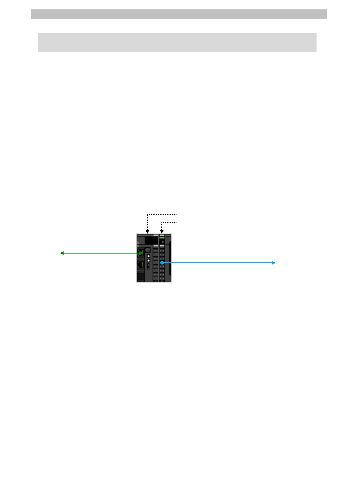
E
IO
Slave Terminal
Performs EtherNet/IP
communications with PLC.
Performs IO
with Photoelectric Sensor.
4. Overview
This document describes the procedures f or connecting E3Z-series IO-Link Photoelectric
Sensor (hereinafter referred to as Photoelectric Sensor) that is connected via IO-Link to
IO-Link Master Unit (NX-ILM[][][]) to CJ-series Programmable Controller + EtherNet/IP Unit
(hereinafter referred to as PLC) via EtherNet/ IP through EtherNet/IP Coupler Unit
(NX-EIC202) to which IO-Link Master Unit is connected and also for checking their
communication status - all of which are produc ed by OMRON Corporation.
Refer to Section 6. Communications Settings and Section 7. IO-Link Connection Procedure to
understand setting methods and key points to perform cyclic communications in the IO-Link
system.
In this document, a specific EtherNet/IP slave configured of EtherNet/IP Coupler Unit and
IO-Link Master Unit is called "Slave Terminal".
Also, CJ-series EtherNet/IP Unit and the built-in EtherNet /IP port of CJ-series CJ2 CPU Unit
are collectively called "EtherNet/IP Unit''.
<Slave Terminal Configuration>
therNet/IP Coupler Unit (NX-EIC202)
-Link Master Unit (NX-ILM[][][])
-Link communications
Page 9

5.Applicable Devices and Device Configuration
6
EtherNet/IP Coupler Unit
Precautions for Correct Use
the devices.
Additional Information
5. Applicable Devices and Device Configuration
5.1. Applicable Devices
The applicable devices are as follows:
Manufacturer Name Model
OMRON CJ2 CPU Unit CJ2[]-CPU[][]
OMRON EtherNet/IP Unit CJ1W-EIP21
CJ2H-CPU6[]-EIP
CJ2M-CPU3[]
OMRON NX-series
NX-EIC202
OMRON NX-series
IO-Link Master Unit
OMRON E3Z-series
IO-Link Photoelectric Sensor
In this document, the devices with models and versions listed in 5.2. Device Configuration are
used as examples of applicable devices to des cribe the procedures for connecting the
devices and checking their connections.
You cannot use devices with versions lower than the versions list ed in 5.2.
To use the above devices with models not listed in 5.2. or versions higher than t hose listed in
5.2., check the differences in the specifications by referring to t he manuals before operating
This document describes the procedures f or establishing the network connections.
It does not provide information on operation, installation, wiring method, device functional it y,
or device operation, which is not related to the connection procedures.
Refer to the manuals or contact the device manufac turer.
NX-ILM[][][]
E3Z-[]8[]-IL[]
Page 10
5.Applicable Devices and Device Configuration
7
Manufacturer
Name
Model
Version
OMRON
CJ2 CPU Unit
(Built-in EtherNet/IP port)
CJ2M-CPU32
Ver.2.0
(Ver.2.12)
OMRON
Power Supply Unit
CJ1W-PA202
OMRON
Switching hub
W4S1-05C
Ver.1.00
-
Switching hub power supply (24 VDC)
-
OMRON
CX-One
CXONE-AL[][]C-V4
/AL[][]D-V4
Ver.4.[][]
OMRON
CX-Programmer
(Included in CX-One)
Ver.9.61
OMRON
Network Configurator
(Included in CX-One)
Ver.3.59c
-
Personal computer (OS: Windows 7)
-
-
USB cable
(USB 2.0 type B connector)
- -
LAN cable (STP (shielded,
category 5 or higher)
OMRON
NX-series
EtherNet/IP Coupler Unit
NX-EIC202
Ver.1.0
OMRON
NX-series
IO-Link Master Unit
NX-ILM400
Ver.1.0
-
Unit power supply (24 VDC)
- -
I/O power supply (24 VDC)
-
OMRON
Sysmac Studio
NX-IO Edition
SYSMAC-NE001L
Ver.1.16
OMRON
CX-ConfiguratorFDT
(Included in
Sysmac Studio)
Ver.2.2
-
USB cable
(USB 2.0 type B connector)
OMRON
IO-Link Photoelectric Sensor
E3Z-D82-IL3 2M
Ver.1.00
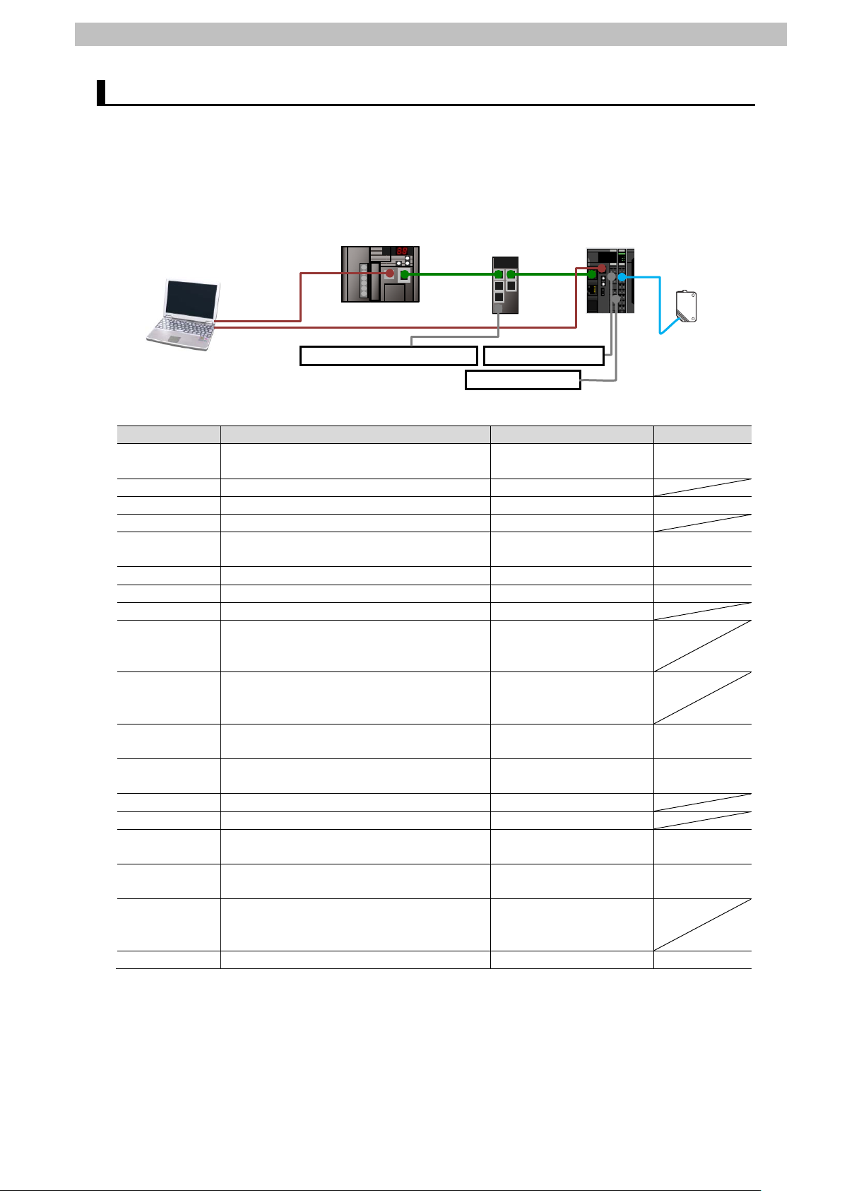
NX-EIC202+
NX-ILM400
Personal computer (CX-One,
I/O power supply
USB
cable
Unit power supply
E3Z-D82-IL3 2M
Switching hub power supply
LAN
cable
LAN
cable
USB cable
CJ2M-CPU32
W4S1-05C
5.2. Device Configuration
The hardware components to reproduce the connect i on procedures in this document are as
follows:
Sysmac Studio, and
CX-ConfiguratorFDT
installed,
OS: Windows 7)
(Built-in EtherNet/IP port)
(for PLC)
twisted-pair) cable of Ethernet
(for Slave Terminal)
Page 11

5.Applicable Devices and Device Configuration
8
Precautions for Correct Use
Precautions for Correct Use
Additional Information
Additional Information
Additional Information
Additional Information
Update CX-Programmer and Network Configurator to the versions specified in this Clause
5.2. or to higher versions. If you use a version higher than the one specified, the procedures
and related screenshots described in Section 7. and subsequent sections may not be
applicable. In that case, use the equivalent procedures described in this document by
referring the CX-Programmer OPERATION MANUAL (Cat. No. W446) and Network
Configurator Online Help.
Update Sysmac Studio and CX-ConfiguratorFDT to the versions specified in this Clause 5.2.
or to higher versions. If you use a version higher than t he one specified, the procedures and
related screenshots described in Section 7. and subsequent sections may not be applicable.
In that case, use the equivalent procedures described i n this document by referring to the
Sysmac Studio Version 1 Operation Manual (Cat. No. W504) and the CX-ConfiguratorFDT
Online Help.
For power supply specifications available f or Switching hub, refer to the Switching Hub
W4S1-series Users Manual (Cat. No. 0969584-7).
For specifications of Unit and I/O power supplies for Slave Terminal, refer to the NX-series
EtherNet/IP
TM
Coupler Unit User’s Manual (Cat. No. W536).
The system configuration in this document uses USB for the connection between Personal
computer and PLC. For information on how to install the USB driver, refer to A-5 Installing the
USB Driver of the CJ-series CJ2 CPU Unit Hardware User's Manual (Cat. No. W472).
The system configuration in this document uses USB for the connection between Personal
computer and Slave Terminal. For information on how to install the USB driver, refer to A-1
Driver Installation for Direct USB Cable Connection in Appendices of the Sysmac Studio
Version 1 Operation Manual (Cat. No. W504).
Page 12
6.Communications Settings
9
IP address
192.168.250.1
192.168.250.2
Item
Set value
Port1 IO-Link Device Configuration Data / Master Control
IO-Link Mode (Default)
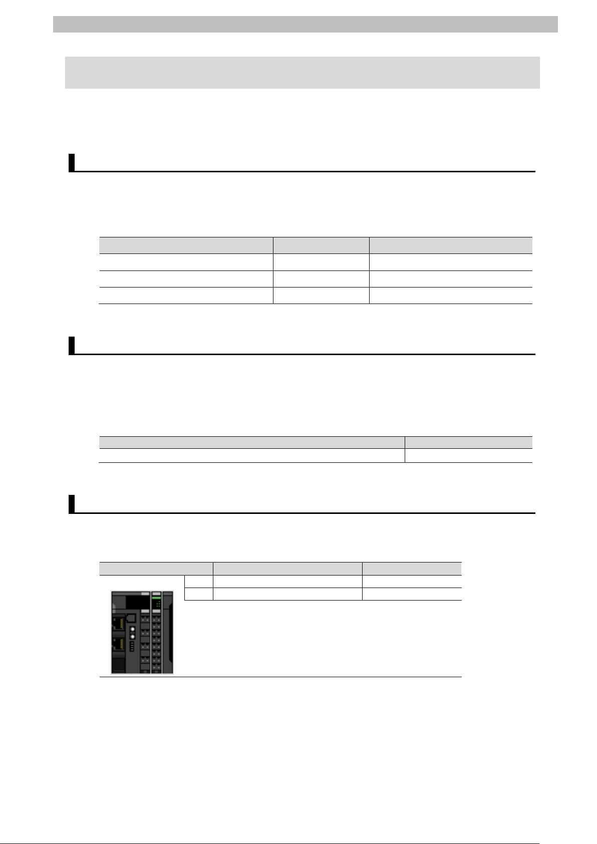
NX Unit number
Name
Model
0
EtherNet/IP Coupler Unit
NX-EIC202
1
IO-Link Master Unit
NX-ILM400
0
1
6. Communications Settings
This section describes the contents of the parameter and tag data link settings that are all
defined in this document.
6.1. EtherNet/IP Connection Parameters
The parameters required for connecting PLC to Sl ave Terminal via EtherNet/IP are shown
below.
<PLC and Slave Term inal Settings>
Item PLC (Node 1) Slave Terminal (Node 2)
Subnet mask 255.255.255.0 255.255.255.0
Network interface setting - Enable Tag Data Links
6.2. IO-Link Connection Parameter
The parameter required for connecting IO-Link Master Unit and Photoelectric Sensor via
IO-Link is shown below.
In this document, Photoelectric Sensor is connected to Port 1 on IO-Link Master Unit.
<IO-Link Master Unit Setting>
6.3. Slave Terminal Configuration
The Slave Termi nal configuration is shown below.
<Slave Terminal Configuration and Device Names>
Page 13
6.Communications Settings
10
Address
Bit
Function name
D10000
0 to 15
Port 1 Output Data01
D10001
0 to 15
Port 2 Output Data01
D10002
0 to 15
Port 3 Output Data01
D10003
0 to 15
Port 4 Output Data01
Address
Bit
Function name
0 to 15
Slave Terminal Status
0 to 3
-
4 Slave Termi nal Observation
5 Slave Terminal Minor Fault
6 Slave Terminal Partial Fault
7 Slave Terminal Major Fault
8 to 13
-
14
Error Detection Flag
15
I/.O Refresh Flag
0 to 15
I/O Port Status
0 Port1 IN Data Enable
1 Port2 IN Data Enable
2 Port3 IN Data Enable
3 Port4 IN Data Enable
4 to 13
-
14
Communication Module Error
15
I/O Power On
0 to 15
Port1_2 I/O Port Error Status
0 Port1 Communication Error
1 Port1 Short Error
2 Port1 Compare Error
3 Port1 Device IO Size Error
4 Port1 Device Error
5 Port1 Device Information
6 Port1 PDO Error
7 - 8 to 15
Port2 Communication Error (Same status as for P ort 1)
0 to 15
Port3_4 I/O Port Error Status
0 to 7
Port3 Communication Error (Same status as for Port 1)
8 to 15
Port4 Communication Error (Same status as for P ort 1)
6.4. Tag Data Link Settings
The I/O data (process data) for Photoelectric Sensor are allocated to the tag data links for
Slave Terminal.
The following shows the content of the tag data link settings for Slave Terminal.
Output area Input area
D10000
(PLC to Slave Terminal)
8 bytes
D10003
■Output area (PLC to Slave Terminal)
D10100
(Slave Terminal to PLC)
16 bytes
D10107
■Input area (Slave Terminal to PLC)
D10100
D10101
D10102
D10103
Page 14
6.Communications Settings
11
Port 1 Input Data01
<Stores the I/O data for Photoelectric Sensor.>
0 to 7
<Stores Byte0 (PD0).>
8 to 15
<Stores Byte1 (PD1).>
D10105
0 to 15
Port 2 Input Data01
D10106
0 to 15
Port 3 Input Data01
D10107
0 to 15
Port 4 Input Data01
0:OFF
1:ON
0:OFF
1:ON
Instability
Receiving)
0:Stable
Instability
Receiving)
0:Stable
Diagnostic output when the sensor
1:Error (ON)
Diagnostic output when the sensor has
1:Error (ON)
0 to 15
D10104
■I/O data (process data) for Photoelectric Sensor
(Data to be stored in the address D10104 listed i n the t abl e above)
Byte0 (PD0) Assignment Details
7 6 5 4 3 2 1 0 Monitor output The Sensing data are output as eight
bits (0-255).
Byte1 (PD1) Assignment Details
7 6 5 4 3 2 1 0 Control Output1
Control Output2
Reserved 0
Alarm(Non-Light
Alarm(Light
Reserved 0
Warning
Error
1:Unstable
1:Unstable
cannot continue operation due to a
recoverable factor such as a load
short-circuit or a service data error
0:Normal (OFF)
an internal error such as the
emitting circuit destruction and
replacement is needed
0:Normal (OFF)
Page 15

7.IO-Link Connection Procedure
12
7.2. Slave Terminal Setup
Set up Slave Terminal.
Configure Slave Terminal, set hardware switches,
and connect Photoelectric Sensor.
Start Sysmac Studio and connect online with S lave
Set the Slave Terminal configuration information.
Set the parameters for IO-Link Master Unit.
Set the I/O allocations for IO-Link Master Unit.
Transfer the setting data of Slave Term inal to
EtherNet/IP Coupler Unit.
7.3. PLC Setup
Set up PLC.
Set the hardware switches on EtherNet/IP Unit and
wire the network.
Start CX-Programmer and connect online with
Create the I/O table and set the IP address of PLC.
7. IO-Link Connection Procedure
This section describes the procedures for connecting Photoelectric Sensor to IO-Link Mas ter
Unit via IO-Link and for connecting PLC to Slave Terminal configured of IO-Link Master Unit
on the EtherNet/IP network. The explanations of procedures for setting up PLC and Slave
Terminal given in this document are based on the factory default settings.
For the initialization, refer to Section 8. Initialization Method.
7.1. Work Flow
Take the following steps to connect Photoelectric Sensor to IO-Link Master Unit via IO-Link
and to connect PLC to Slave Terminal configured of IO-Link Master Unit on the EtherNet/IP
network.
↓
7.2.1. Hardware Settings
↓
7.2.2. Starting Sysmac Studio and
Connecting Online with Slave
Terminal
↓
7.2.3. S etting the Slave Terminal
Configuration Information
↓
7.2.4. IO-Link Master Unit Setup
↓
7.2.5. I/O Allocation Settings
↓
7.2.6. Transferring the Setting Data
↓
Terminal.
↓
7.3.1. Hardware Settings
↓
7.3.2. S tarting CX-Programmer and
Connecting Online with PLC
↓
7.3.3. Creat i ng the I/O Table and
Setting the IP Address
↓
PLC.
Page 16

7.IO-Link Connection Procedure
13
Communications
Set the EtherNet/IP tag data links.
PLC
Start Network Configurator and connect onli ne wi th
Upload the network configuration.
Register tags for input (consume) and output
(produce).
Associate the tags of the target device with the
tags of the originator device.
Transfer the set tag data link parameters to PLC.
Check
Confirm that cyclic communications in the IO-Link
Check the connection status of each device.
Check that the correct data are received.
7.4. Network Settings for Host
↓
7.4.1. Starting Network Configurator
and Connecting Online with
↓
7.4.2. Uploading the Network
Configuration
↓
7.4.3. Setting the Tags
↓
7.4.4. Setting the Connections
↓
7.4.5. Transferring the Tag Data Link
Parameters
PLC.
↓
7.5. IO-Link Communication Status
↓
7.5.1. Checking the Connection Status
↓
7.5.2. Checking the Receive Data
system performs normally.
Page 17
7.IO-Link Connection Procedure
14
1
applicable.
2
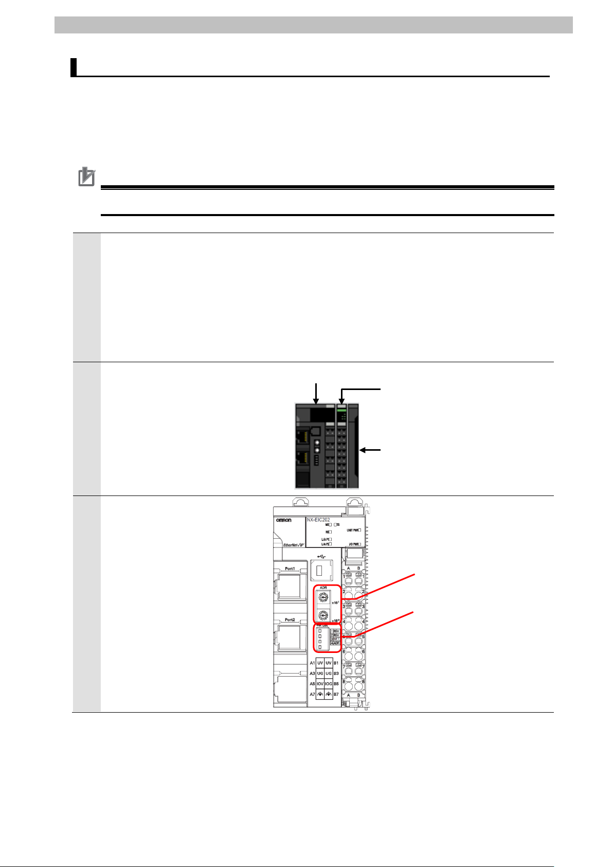
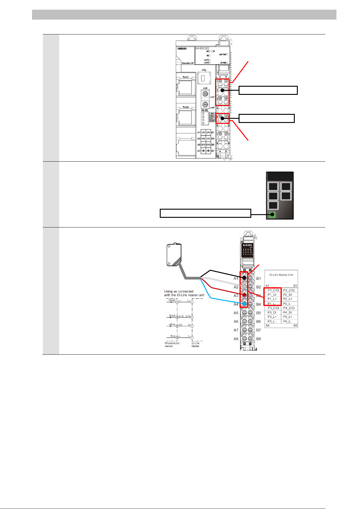
IO-Link Master Unit
End Cover
EtherNet/IP Coupler Unit
Rotary switches
Dip switch
7.2. Slave Terminal Setup
Set up Slave Terminal.
Hardware Settings 7.2.1.
Configure Slave Terminal, set hardware switches, and connect Photoelectric Sens or.
Precautions for Correct Use
Make sure that the power supply is OFF when you set up.
Make sure that EtherNet/IP
Coupler Unit and IO-Link Master
Unit are powered OFF.
*If either of them is ON, the
settings described in the
following steps and subsequent
procedures may not be
Connect IO-Link Master Unit to
EtherNet/IP Coupler Unit.
Check the position of the
3
hardware switches on
EtherNet/IP Coupler Unit by
referring to the figure on the
right.
Page 18
15
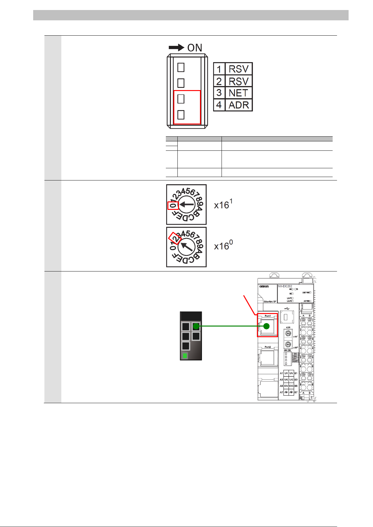
Check that Dip switch is set as
Pin
Name
Meaning
Pin 1
Reserved by the system
Keep turned OFF
(The factory setting is OFF)
Pin 2
Pin 3
Network interface setting
ON: Enable UDP/IP communications and TCP/IP
communications and TCP/IP communications)
Pin 4
IP address base setting
ON: 192.168.1.[] (with [] set by rotary switches)
OFF: 192.168.250.[] (with [] set by rotary switches)
5
6
LAN cable
Communications connector
Switching hub
4
follows:
SW3 NET: OFF
SW4 ADR: OFF
*The tag data links become
enabled, and the first to third
octets of the IP address are set
to 192.168.250.
*The forth octet of the IP
address is set by Rotary
switches.
Set Rotary switches as follows:
1
x16
: 0
0
x16
: 2
*The IP address is set to
192.168.250.2.
7.IO-Link Connection Procedure
communications(disable Tag Data Links)
OFF: Enable Tag Data Links (disable UDP/IP
Connect Switching hub and
Communications connector
(Port 1) on EtherNet/IP Coupler
(Port 1)
Unit with a LAN cable.
Page 19
16
Connect Unit power supply and
8
0969584-7).
9
Switching hub power supply
Black
White
Brown
Blue
Photoelectric Sensor
IO-Link
Master Unit
Port 1
Unit power supply
I/O power supply
Unit power supply terminals
I/O power supply terminals
NX-ILM400
7
I/O power supply to Unit power
supply terminals and I/O power
supply terminals on EtherNet/IP
Coupler Unit, respectively.
*For connecting the power
supplies for NX-series Slave
Terminals, refer to NX-series
EtherNet/IP
User’s Manual (Cat. No.
W536).
TM
Coupler Unit
7.IO-Link Connection Procedure
Connect Switching hub power
supply to Switching hub.
*For connecting Switching hub
power supply, refer to the
Switching Hub W4S1-series
Users Manual (Cat. No.
Connect Photoelectric Sensor to
Port 1 on IO-Link Master Unit.
Page 20
7.IO-Link Connection Procedure
17
1
2
Terminal remains OFF.
3
Sysmac Studio.
4
5
Create
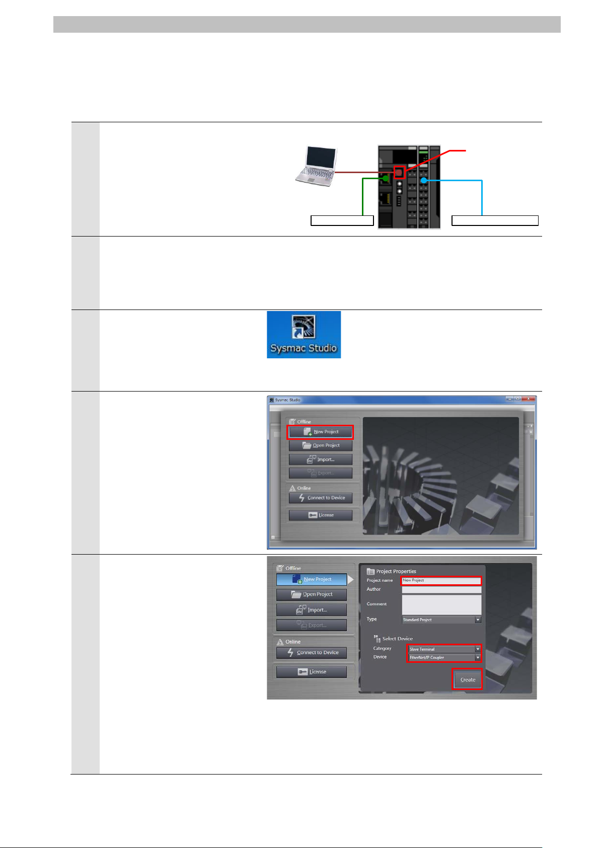
Peripheral
(USB) port
Photoelectric Sensor
Slave Terminal
Switching hub
Personal computer
USB
cable
Starting Sysmac Studio and Connecting Online with Slave Terminal 7.2.2.
Start Sysmac Studio and connect online with S lave Terminal.
Install Sysmac Studio and the USB driver on Personal computer beforehand.
Connect the peripheral USB
port on Slave Terminal to
Personal computer with a USB
cable.
Turn ON Unit power supply for
Slave Terminal.
*The I/O power supply for Slave
Start Sysmac Studio.
*If the User Account Control
Dialog Box is displayed at
start, make a selection to start
Sysmac Studio starts.
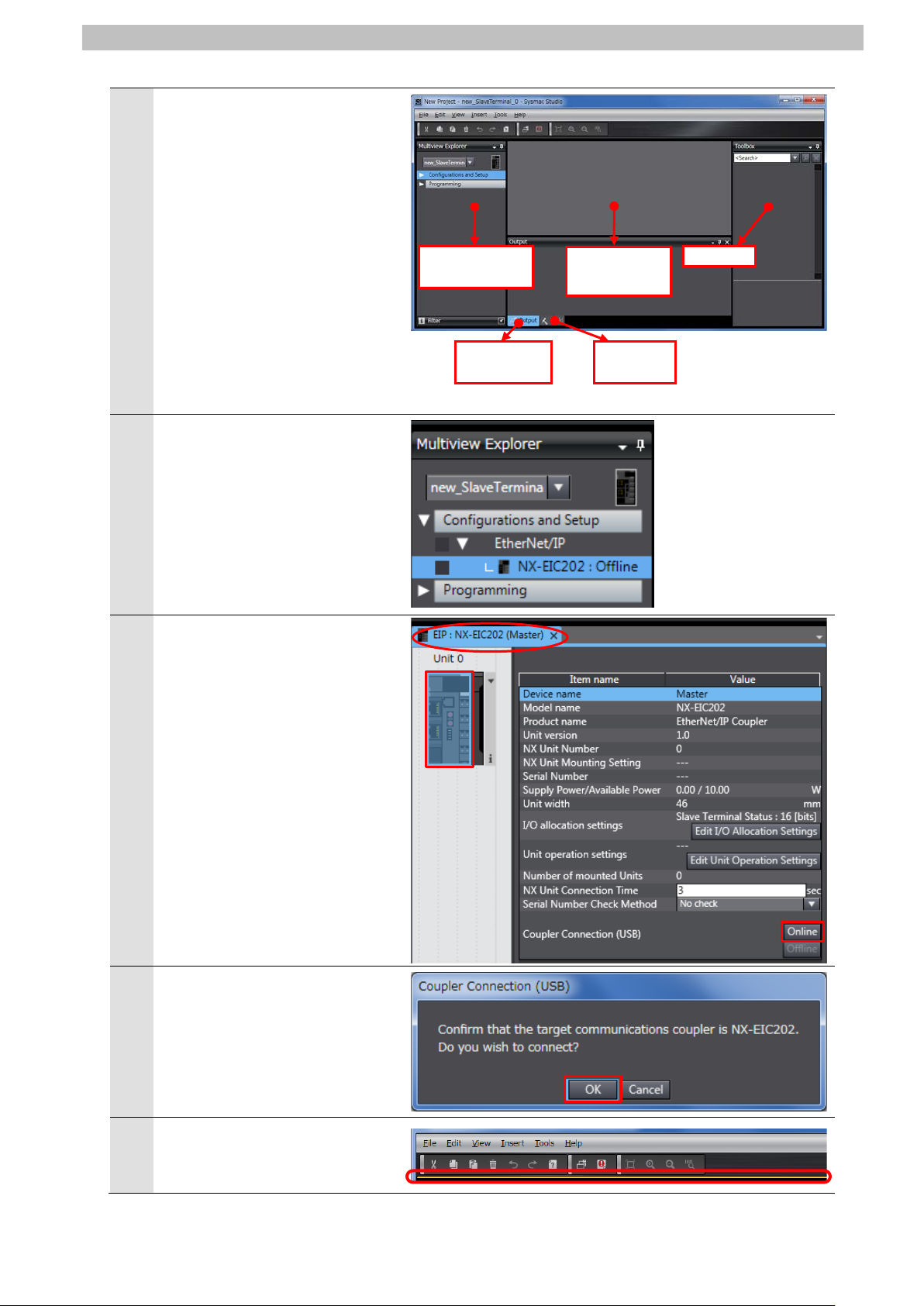
Click New Project.
The Project Properties Dialog
Box is displayed.
Enter a project name.
*In this document, New Project
is used as the project name.
Select the following device
category and the device to use
in the Select Device Area.
・Category: Slave Term inal
・Device: EtherNet/IP Coupler
Click
.
Page 21
18
The New Project is displayed.
Build Tab Page
7
8
9
10
Toolbox
Edit
Multiview
Output T ab
Build T ab
6
The following panes are
displayed in this window.
Left: Multiview Explorer
Top right: Toolbox
Top middle: Edit Configuration
Pane
The following tabs are displayed
in the bottom middle of this
window.
Output Tab Page
Double-click NX-EIC202 under
Configurations and Setup EtherNet/IP in the Multiview
Explorer.
Explorer
Page
7.IO-Link Connection Procedure
Configuration
Page
The EIP : NX-EIC202 (Master)
Tab Page is displayed in the
Edit Configuration Pane.
Select the device icon of
EtherNet/IP Coupler Unit (Unit
0) and click Online.
The dialog box on the right is
displayed. Check the contents
and click OK.
When an online connection is
established, a yellow bar is
displayed under the toolbar.
Page 22

19
Setting the Slave Terminal Configuration Information 7.2.3.
1
2
3
Set the Slave Terminal configuration information.
Right-click the device icon of
EtherNet/IP Coupler Unit (Unit
0) and select Compare and
Merge with Actual Unit
Configuration.
7.IO-Link Connection Procedure
The Compare and Merge with
Actual Unit Configuration Dialog
Box is displayed.
Check that IO-Link Master Unit
is displayed in Actual Unit
Configuration and that Added is
shown in the Result Column.
Click Apply Actual Unit
Configuration.
Check that IO-Link Master Unit
is displayed in Configuration on
Sysmac Studio and that
Matched is shown in the Result
Column.
Click OK.
Page 23

20
The IO-Link Master Unit is
5
Select
Check the added unit.
4
added next to EtherNet/IP
Coupler Unit on the EIP :
NX-EIC202 (Master) T ab Page.
Select the device icon of
EtherNet/IP Coupler Unit (Unit
0) and click Offline.
7.IO-Link Connection Procedure
Check that EtherNet/IP Coupler
Unit goes Offline.
The yellow bar under the toolbar
disappears when offline.
Page 24

7.IO-Link Connection Procedure
21
Additional Information
1
3
IO-Link Master Unit Setup 7.2.4.
Set the parameters for IO-Link Master Unit.
In this document, the default values are used for the parameter settings of IO-Link Master Unit.
Check that IO-Link Mode is set as the communications mode for Port 1 to which Photoelectric
Sensor is connected.
If you use the functions such as the connected device verification and the backup and
restoration of parameter settings in IO-Link devi ces, refer to the NX-series IO-Link Master
Unit User's Manual (Cat. No. W567) and the IO-Link System User's Manual (Cat. No. W570).
Select the device icon of IO-Link
Master Unit (NX Unit number 1)
on the EIP : NX-EIC202
(Master) Tab Page.
Click Edit Unit Operation
Settings.
The Unit 1 [EIP]:NX-ILM400(N1)
2
Unit Operation Settings Tab
Page is displayed.
Select ▼Port1 - Port1 IO-Link
Device Configuration Data
from the pull-down list (just
above the column "Item name")
to narrow down the parameters.
Page 25

22
A list of Port1 IO-Link Device
mode from the pull-down list.
4
Configuration Data is displayed.
Check that IO-Link Mode is
selected as the set value of
Port1 IO-Link Device
Configuration Data/Master
Control.
*If IO-Link Mode is not displayed
in the Value Column, select the
7.IO-Link Connection Procedure
Page 26

7.IO-Link Connection Procedure
23
Additional Information
I/O Allocation Settings 7.2.5.
Set the I/O allocations for IO-Link Master Unit.
As the default values are used for the I/O allocati ons in this document, the I/O allocation
settings are made without editing any of the values.
To save the I/O data size for
unused ports, delete the I/O
entries for the unused ports
from the I/O allocation settings.
The Edit I/O Allocation Settings
Pane is displayed by clicking
Edit I/O Allocation Settings
shown on the right.
For information on how to edit,
refer to the IO-Link System
User's Manual (Cat. No.
W570).
Page 27

7.IO-Link Connection Procedure
24
1
Slave Terminal.
2
3
4
Transferring the Setting Data 7.2.6.
Transfer the setting data of Slave Term inal to EtherNet/IP Coupler Unit.
Select the device icon of
EtherNet/IP Coupler Unit on the
EIP : NX-EIC202(Master) Tab
Page in the Edit Configuration
Pane, and connect online with
EtherNet/IP Coupler Unit in the
same way as steps 8 to 10 in
7.2.2. Starting Sysmac Studio
and Connecting Online with
Right-click the device icon of
EtherNet/IP Coupler Unit (Unit
0) and select Coupler
Connection (USB) - Transfer
to Coupler from the menu.
The Transfer to Coupler Dialog
Box is displayed.
Click Configuration
information + Unit operation
settings + Unit application
data.
The dialog box on the right is
displayed. Check the contents
and click Yes.
A screen is displayed stating
"Transfer to Coupler".
The transfer is completed when
the screen is closed.
Page 28

25
Select the device icon of
6
7
5
EtherNet/IP Coupler Unit (Unit
0) and click Offline.
Check that EtherNet/IP Coupler
Unit goes offline.
7.IO-Link Connection Procedure
Select Exit from the File Menu
to close Sysmac Studio.
The dialog box on the right is
displayed. Check the contents
and click No.
*If desired, save the project file.
Page 29

7.IO-Link Connection Procedure
26
1
applicable.
2
3
4
Seven-segment display
Unit number setting switch
Node address setting switches
7.3. PLC Setup
Set up PLC.
Hardware Settings 7.3.1.
Set the hardware switches on EtherNet/IP Unit and wire the network.
Precautions for Correct Use
Make sure that the power supply is OFF when you set up.
Make sure that PLC and
Switching hub are powered
OFF.
*If either of them is ON, the
settings described in the
following steps and subsequent
procedures may not be
Check the positions of the
hardware switches and the
display on the front panel of
EtherNet/IP Unit by referring to
the figure on the right.
Set Unit number setting switch
to 0.
Set Node address setting
switches to the following default
settings.
NODE No.x16
NODE No.x16
*The IP address is set to
192.168.250.1.
1
0
: 0
: 1
*By default, the first to third octets of the local IP address
are fixed to 192.168.250. The fourth octet is a value that
is set with Node address setting switches.
Page 30

27
Connect a LAN cable to the
6
hub.
7
Personal computer
Slave Terminal
LAN cable
PLC
USB cable
Switching hub
LAN cable
Photoelectric Sensor
5
EtherNet/IP port on PLC, and
connect a USB cable to the USB
port. As shown in 5.2. Device
Configuration, connect Personal
computer and Switching Hub to
PLC.
7.IO-Link Connection Procedure
USB cable
Turn ON PLC and Switching
The set IP address is displayed
on Seven-segment display.
Afterwards, the rightmost 8 bits
of the IP address is displayed in
hexadecimal during normal
operation.
Page 31

7.IO-Link Connection Procedure
28
1
CX-Programmer.
2
3
4
Starting CX-Programmer and Connecting Online with PLC 7.3.2.
Start CX-Programmer and connect online with PLC.
Install CX-One and the USB driver on Personal computer beforehand.
Start CX-Programmer.
*If the User Account Control
Dialog Box is displayed at start,
make a selection to start
CX-Programmer starts.
Select Auto Online - Direct
Online from the PLC Menu.
The Direct Online Dialog Box is
displayed. Select USB
connection as the connection
type.
Click Connect.
Page 32

29
The dialog box on the right is
6
7
during online connection.
Additional Information
Additional Information
5
displayed. Check the contents
and click No.
The dialog box on the right is
displayed.
CX-Programmer and PLC are
automatically connected.
Check that CX-Programmer and
PLC are connected online.
7.IO-Link Connection Procedure
*The icon is press ed down
If PLC cannot be connected online, check the cable c onnection.
Or, return to step 1, check the settings and repeat each step.
For details, refer to Connecting Directly to a CJ2 CPU Unit Using a USB Cable of the
CX-Programmer OPERATION MANUAL (Cat. No. W446).
The dialog boxes explained in the subsequent procedure may not be displayed depending on
the environmental settings of CX-Programmer.
For details on the environmental settings, refer to Options and Preferences in CHAPTER 3
Project Reference in PART 1: CX-Programmer of the CX-Programmer OPERATION
MANUAL (Cat. No. W446).
This document explains the setting procedures when ''Confirm all operations affecting the
PLC'' is selected.
Page 33

30
1
2
Creating the I/O Table and Setting the IP Address 7.3.3.
Create the I/O table and set the IP address of PLC.
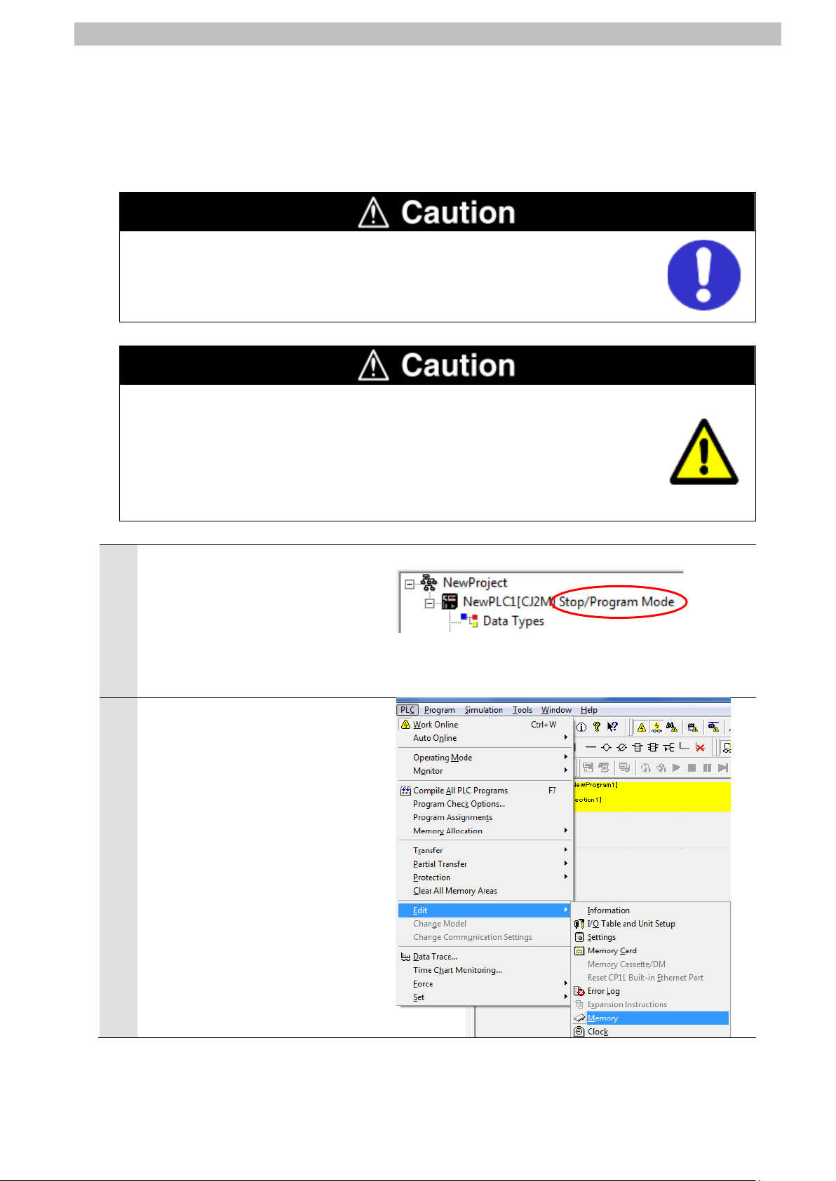
If the operating mode of PLC is
Run Mode or Monitor Mode,
change it to Program Mode by
following the steps below.
(1)Select Operating Mode -
Program from the PLC Menu
in CX-Programmer.
(2)The dialog box on the right is
displayed. Confirm that there
is no problem, and click Yes.
*Refer to Additional
Information on the previous
page for the settings
concerning the dialog display.
(3)Check that Stop/Program
Mode is displayed on the right
of the PLC model in the
Project Workspace of
CX-Programmer.
Select Edit - I/O Table and Unit
Setup from the PLC Menu in
CX-Programmer.
The PLC IO Table Window is
displayed.
(Project Workspace)
7.IO-Link Connection Procedure
Page 34

31
Precautions for Correct Use
3
7.IO-Link Connection Procedure
The PLC is reset after creating and transferring the I/O table in step 3 and subsequent steps.
Always confirm safety before creating and transferring the I/O table.
Select Create from the Options
Menu in the PLC IO Table
Window.
The dialog box on the right is
displayed. Confirm that there is
no problem, and click Yes.
The dialog box on the right is
displayed. Confirm that there is
no problem, and click Yes.
Page 35

7.IO-Link Connection Procedure
32
The Transfer from PLC Dialog
4
Box is displayed. Select IO
Table and SIO Unit Parameters.
Click Transfer.
When the transfer is completed,
the Transfer Results Dialog Box
is displayed.
Check that the transfer is
successfully completed by
referring to the message in the
dialog box.
When the I/O table is created
normally, the dialog box displays
as follows:
Transfer Success: 1 Unit
Transfer Unsuccessful: 0 Unit
Click OK.
Page 36

33
In the PLC IO Tabl e Window,
5
click + to the left of Built-in
Port/Inner Board to display
CJ2M-EIP21.
*The figure on the right displays
CPU Unit (Built-in EtherNet/IP
port) specified in 5.2. Device
Configuration. If you use an
other applicable EtherNet/IP
Unit, the display position and
name are different from the
figure on the right.
Right-click CJ2M-EIP21 and
select Unit Setup.
7.IO-Link Connection Procedure
The Edit Parameters Dialog Box
6
is displayed.
Select the TCP/IP Tab.
Make the following settings in
the IP Address Field.
・Use the following address:
Select
・IP address: 192.168.250.1
・Subnet mask: 255.255.255.0
Click Transfer[PC to Unit].
Page 37

34
The dialog box on the right is
8
7
displayed. Confirm that there is
no problem, and click Yes.
Check that a message is
displayed stating "Transfer
successful". Click Close.
7.IO-Link Connection Procedure
The dialog box on the right is
displayed. Check the contents
and click Yes.
When the Unit is restarted, the
dialog box on the right is
displayed. Check the contents
and click OK.
Page 38

35
Click Compare to check that the
10
11
9
IP address is correctly changed.
Check that a message is
displayed stating "Compare
successful". Click Close.
7.IO-Link Connection Procedure
Click OK in the Edit Parameters
Dialog Box.
Page 39

7.IO-Link Connection Procedure
36
1
2
7.4. Network Settings for Host Communications
Set the EtherNet/IP tag data links.
Starting Network Configurator and Connecting Online with PLC 7.4.1.
Start Network Configurator and connect onli ne wi th PLC.
Right-click CJ2M-EIP21 in the
PLC IO Table Window, and
select Start Special
Application - Start with
Settings Inherited.
The Select Special Application
Dialog Box is displayed.
Select Network Configurator and
click OK.
Network Configurator starts.
The following panes are
displayed in this window.
Left: Hardware List
Right: Network Configuration
Pane
Network Configuration Pane Hardware List
Page 40

7.IO-Link Connection Procedure
37
Precautions for Correct Use
3
4
6
Check that the LAN cables are connected before performing the following steps.
If they are not connected, turn OFF each of the devices, and then connect the LAN cables.
Select Select Interface - CJ2
USB/Serial Port from the
Option Menu.
Select Connect from the
Network Menu.
The Setup Interface Dialog Box
5
is displayed.
Check that the following settings
are made.
Port Type: USB
Port: OMR0
Baud Rate: 115200 Bit/s
Click OK.
The Select Connect Network
Port Dialog Box is displayed.
Select BackPlane CJ2M-EIP21 - TCP:2.
Click OK.
Page 41

38
The Select Connected Network
8
7
Dialog Box is displayed.
Check the contents and click
OK.
When an online connection is
established normally, the color
of the icon changes to blue as
shown on the right.
7.IO-Link Connection Procedure
Additional Information
If PLC cannot be connected online, check the cable c onnection.
Or, return to step 3, check the settings and repeat each step.
For details, refer to 6-2-9 Connecting the Network Configurator to the Network in SECTION 6
Tag Data Link Functions of the EtherNet/IP
TM
Units OPERATION MANUAL (Cat. No. W465).
Page 42

39
Uploading the Network Configuration 7.4.2.
1
3
Upload the network configuration.
Select Upload from the Network
Menu to upload the device
information on the network.
The dialog box on the right is
2
displayed.
Confirm that there is no
problem, and click Yes.
7.IO-Link Connection Procedure
The Target Devic e Di alog Box is
displayed.
Select 192.168.250.1 and
192.168.250.2.
Click OK.
*If 192.168.250.1 and
192.168.250.2 are not
displayed in the dialog box,
click Add to add the
addresses.
*A displayed address depends
on the status of Network
Configurator.
The device parameters are
4
uploaded. When the uploading
is completed, the dialog box on
the right is displayed.
Check the contents and click
OK.
Page 43

40
Check that the uploaded nodes
5
with the following IP addresses
are configured in the Network
Configuration Pane.
IP address of node 1:
192.168.250.1
IP address of node 2:
192.168.250.2
7.IO-Link Connection Procedure
Page 44

7.IO-Link Connection Procedure
41
1
3
Setting the Tags 7.4.3.
Register tags for input (consume) and output (produc e).
The following explains the receive and send s ettings of the target device in order.
In the Network Configuration
Pane of Network Configurator,
right-click the node 1 device and
select Parameter - Edit.
The Edit Device Parameters
2
Dialog Box is displayed.
Select the Tag Sets Tab.
The data on the Tag Sets Tab
Page is displayed.
Select the In-Consume Tab and
click Edit Tags.
Page 45

42
The Edit Tags Dialog Box is
5
6
4
displayed.
Select the In - Consume Tab
and click New.
Here, register a tag for the area
where the node 1 consumes
data from the node 2.
7.IO-Link Connection Procedure
The Edit Tag Dialog Box is
displayed. Enter the following
values of the parameters.
Name: D10100 (Start address
of the input data to node 1)
Size: 16 (Byte)
After entering, click Regist.
The Edit T ag s Dialog Box is
displayed again. Click Close.
Page 46

43
Select the Out - Produce Tab
8
9
7
and click New.
Here, register a tag for the area
where the node 1 produces data
to the node 2.
7.IO-Link Connection Procedure
The Edit Tag Dialog Box is
displayed. Enter the following
values of the parameters.
Name: D10000 (Start address
of the output data from node
1)
Size: 8 (Byte)
After entering, click Regist.
The Edit Tag Dialog Box is
displayed again. Click Close.
Page 47

44
When you finish the registration,
11
12
10
click OK in the Edit Tags Dialog
Box.
7.IO-Link Connection Procedure
The dialog box on the right is
displayed. Confirm that there is
no problem, and click Yes.
The Edit Device Parameters
Dialog Box is displayed again.
Select the Connections Tab.
Page 48

7.IO-Link Connection Procedure
45
1
3
Connection I/O Type
Input / Output
Originator Device
Input Tag Set
D10100-[16 Byte]
Connection Type
Multi-cast connection
Output Tag Set
D10000-[8 Byte]
Connection Type
Point to Point connection
Target Device
Output Tag Set
Input_100-[16 Byte]
Input Tag Set
Output_148- [8 Byte]
Setting the Connections 7.4.4.
Associate the tags of the target device (that rec ei ves the open request) with the tags of the
originator device (that requests for openi ng).
Select 192.168.250.2 in the
Unregister Device List Field.
Click the Down Arrow Button
that is shown in the dialog box.
192.168.250.2 is registered in
2
the Register Device List Field.
Select 192.168.250.2 and click
New.
The Edit Connection Dialog Box
is displayed. Select Input /
Output from the pull-down list of
Connection I/O Type.
Set the values listed in the
following table in the Originator
Device and the Target Device
Fields.
■Connection configuration settings
Connection configuration Set value
Page 49

46
Check that the settings are
5
Close
4
correct. Click Regist.
The Edit Connection Dialog Box
is displayed again. Click
The Edit Device Parameters
6
Dialog Box is displayed again.
Click OK.
.
7.IO-Link Connection Procedure
When the connection is
7
completed, the registered node
address is displayed under the
device icon of node 2 in the
Network Configuration Pane.
Page 50

47
Transferring the Tag Data Link Parameters 7.4.5.
1
3
4
Transfer the set tag data link parameters to PLC.
Right-click the device icon of
node 1 in the Network
Configuration Pane and select
Parameter – Download from
the menu.
The dialog box on the right is
2
displayed. Confirm that there is
no problem, and click Yes.
7.IO-Link Connection Procedure
The tag data link parameters are
downloaded from Network
Configurator to PLC.
The dialog box on the right is
displayed. Check the contents
and click OK.
Page 51

7.IO-Link Connection Procedure
48
1
2
3
4
Port number
7.5. IO-Link Communication Status Check
Confirm that cyclic communications in the IO-Link system performs normally.
Checking the Connection Status 7.5.1.
Check the connection status of each device.
Turn ON I/O power supply for Slave
Terminal.
Check with LED indicators on PLC
(EtherNet/IP Unit) that the
EtherNet/IP tag data links operate
normally.
The LED indicators in normal status
are as follows:
MS: Green lit
NS: Green lit
COMM: Yellow lit
100M or 10M: Yellow lit
Check the LED indicators on
EtherNet/IP Coupler Unit.
The LED indicators in normal status
are as follows:
TS: Green lit
MS: Green lit
NS: Green lit
L/A P1: Green flickering
Check the LED indicators on
IO-Link Master Unit.
The LED indicators in normal status
are as follows:
TS: Green lit
Port 1-C: Green lit
Port 1-E: Not lit
Page 52

7.IO-Link Connection Procedure
49
Stability indicator/
IO-Link Communication indicator
Check the LED indicator on
5
Photoelectric Sensor.
The LED indicator in normal status
is as follows:
Stability indicator / IO-Link
Communication indicator:
Green flashing
(1sec cycle)
The normal operation of tag data
6
links is confirmed through the status
information in the Monitor Device
Dialog Box of Network Configurator.
Right-click the device icon of node 1
in the Network Configuration Pane
and select Monitor.
<Top view of Photoelectric Sensor>
The dialog box on the right displays
7
the Status 1 Tab Page in the Monitor
Device Dialog Box.
When the same check boxes are
selected as shown on the right, the
tag data links are normally in
operation.
Click Close.
Number: Node number
Blue: Connection normal
Page 53

50
Select Disconnect from the
9
10
8
Network Menu to go offline.
The color of the icon changes from
blue to gray as shown on the right.
Select Exit from the File Menu to
close Network Configurator.
A confirmation dialog box is
displayed whether or not you save
the changed network configuration.
Click No.
*If desired, save the changed
network configuration.
7.IO-Link Connection Procedure
Page 54
7.IO-Link Connection Procedure
51
1
Setting the IP Address.
Checking the Receive Data 7.5.2.
Check that the correct data are received.
Check that CX-ConfiguratorFDT is being installed on Personal computer.
CX-ConfiguratorFDT is included in Sysmac Studio.
If you wire the I/O in the state where the devices are powered ON, doing so may
cause damage to the devices.
Always read and follow the information provided in all safety precautions in the
manuals for each device to be wired.
If the PLC memory is changed by malfunction during monitoring power flow and
present value status in the Ladder Section Window or in t he Watch Window, the
devices connected to output units may malfunct ion, regardless of the operating
mode of CPU Unit.
Always ensure safety before monitoring power flow and present value status in
the Ladder Section Window or in the Watch Window.
Check that the operating mode of
PLC is Stop/Program Mode.
*If PLC is not in Stop/Program
Mode, change to Stop/Program
Mode by referring to step 1 of
7.3.3. Creating the I/O Table and
Select Edit - Memory from the PLC
2
Menu.
Page 55

52
The PLC Memory Window is
6
7
8
when starting CX-ConfiguratorFDT.
3
displayed. Double-click D on the
Memory Tab of the PLC Memory
Window.
Select Display - Hexadecimal from
4
the View Menu.
7.IO-Link Connection Procedure
Select Monitor from the Online
5
Menu.
The Monitor Memory Areas Dialog
Box is displayed.
Check that D is selected.
Click Monitor.
Enter 10100 in the Start Address
Field of the D Window.
Check that the start address
changes to D10100.
Start CX-ConfiguratorFDT.
*Click Yes if a dialog box to update
the device catalog is displayed
Page 56

53
CX-ConfiguratorFDT starts.
11
9
Right-click MyNetwork in the
Network View and select Add from
the menu.
The Add Dialog Box is displayed.
10
Select NX Coupler USB.
Click OK.
7.IO-Link Connection Procedure
Check that <NX bus> NX Coupler
USB is added under MyNetwork in
the Network View.
Page 57
54
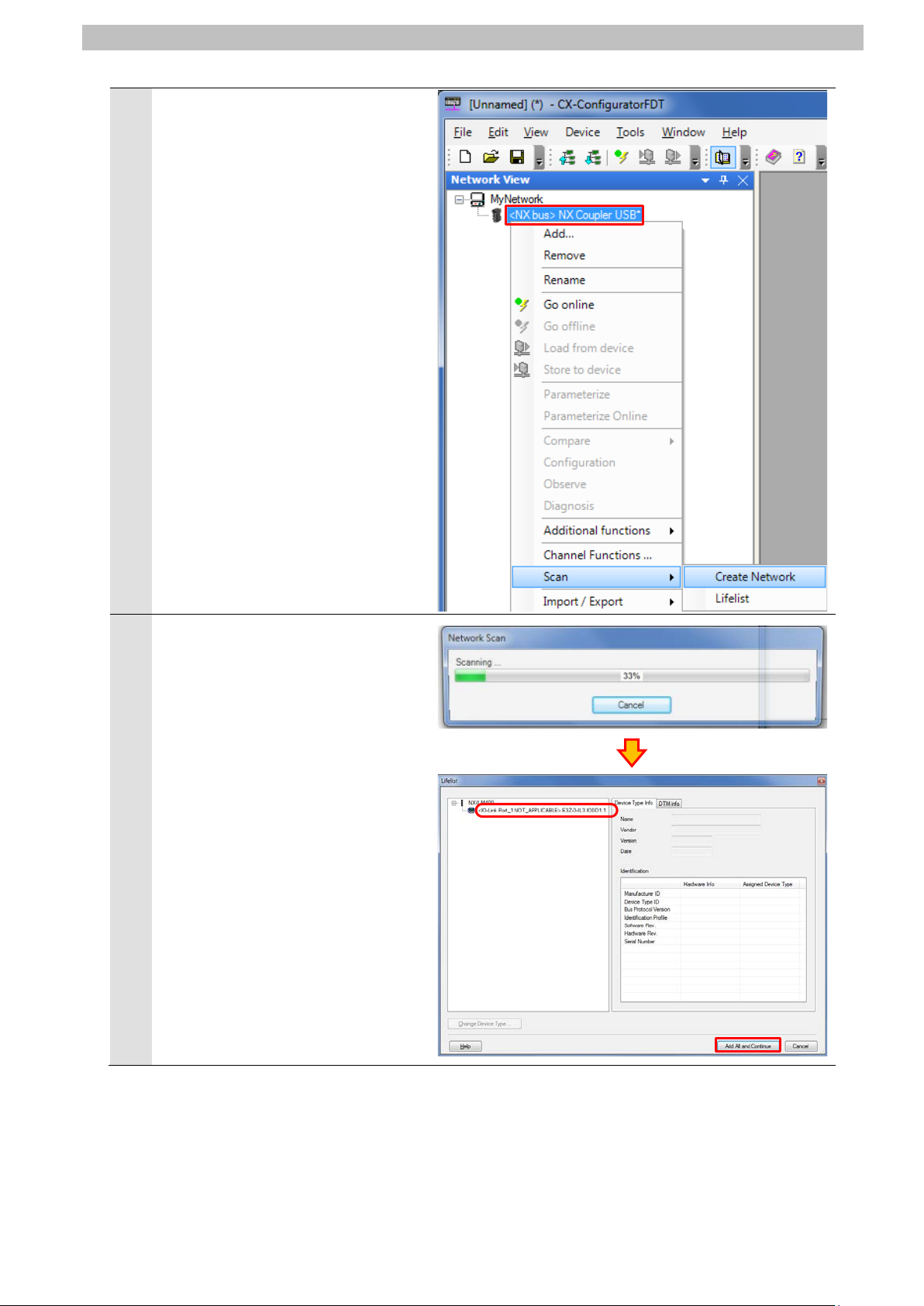
Right-click <NX bus> NX Coupler
13
12
USB and select Scan - Create
Network from the menu.
7.IO-Link Connection Procedure
The Lifelist Dialog Box is displayed
after completing the network scan.
Check that <IO-Link
Port_1:NOT_APPLICABLE>
E3Z-D-IL3 IODD1.1 is added under
NX-ILM400.
Click Add All and Continue.
Page 58

55
Check that the network
15
16
17
14
configuration is created in the
Network View as shown on the right.
Right-click <IO-Link Port_1:->
E3Z-D-IL3 IODD1.1 and select Go
online from the menu.
7.IO-Link Connection Procedure
z
Check that Photoelectric Sensor is
connected online.
Right-click <IO-Link Port_1:->
E3Z-D-IL3 IODD1.1 and select
Configuration from the menu.
*When <IO-Link Port_1:->
E3Z-D-IL3 IODD1.1 is displayed in
bold italic font, Photoelectric
Sensor is connected online.
The <IO-Link Port_1:-> E3Z-D-IL3
IODD1.1 - Configuration T ab Page
is displayed.
Page 59

56
Select Observation listed under
19
20
Photoelectric Sensor.
Operation indicator
<Top view of Photoelect r i c Sensor>
Operation mode switch
Light ON)
18
Menu on the <IO-Link Port_1:->
E3Z-D-IL3 IODD1.1 - Configuration
Tab Page.
If Process Data In on the right side
of the tab page is not expanded,
click the + Button of Process Data In
to expand.
Click the icon (Enable or disable
cyclic read from device for dynamic
variables) on the <IO-Link Port_1:->
E3Z-D-IL3 IODD1.1 - Configuration
Tab Page.
The present values of the process
data for Photoelectric Sensor are
displayed in the Value Column.
7.IO-Link Connection Procedure
Check that Operation mode switch
on Photoelectric Sensor is set to
Light ON (factory setting).
Make sure that there is no sensing
object in front of Photoelectric
Sensor and that Operation indicator
is not lit.
Check that the values of
21
Photoelectric Sensor in
CX-ConfiguratorFDT are as shown
below.
Detection Level: 4
Control Output 2: OFF
Control Output 1: OFF
*The value of the detection level
differs depending on the
environmental settings of
(
Page 60

57
In the PLC Memory Window of
step 21.
23
24
Photoelectric Sensor.
Sensing
object
Operation indicator
<Top view of Photoelectric Sensor>
22
CX-Programmer, check that the
value of D10104 is as shown below.
D10104
Bits 0 to 7: 4 (dec)
Bits 8 and 9: 00 (bin)
*For details on each of the
addresses, refer to 6.4. Tag Data
Link Settings.
*You can check that the monitor
output (Detection Level) of Port 1 is
4 and that the control outputs 1
and 2 are OFF; these values are
the same as the ones described in
Place Sensing object in front of
Photoelectric Sensor and check that
Operation indicator is lit in orange.
7.IO-Link Connection Procedure
D10104
Bits 0 to 7 : 04 (hex) → 4 (dec)
Bits 8 to 15 : 00 (hex) → 00000000 (bin)
↑
(Check that the bits 8 and 9 are 0.)
Check that the values of
Photoelectric Sensor in
CX-ConfiguratorFDT are as shown
below.
Detection Level: 255
Control Output 2: ON
Control Output 1: ON
*The value of the detection level
differs depending on the
environmental settings of
Page 61

58
In the PLC Memory Window of
step 24.
25
CX-Programmer, check that the
value of D10104 is as shown below.
D10104
Bits 0 to 7: 255 (dec)
Bits 8 and 9: 11 (bin)
*For details on each of the
addresses, refer to 6.4. Tag Data
Link Settings.
*You can check that the monitor
output (Detection Level) of Port 1 is
255 and that the control outputs 1
and 2 are ON; these values are the
same as the ones described in
7.IO-Link Connection Procedure
D10104
Bits 0 to 7 : FF (hex) → 255 (dec)
Bits 8 to 15 : 03 (hex) → 00000011 (bin)
↑
(Check that the bits 8 and 9 are 1.)
Page 62

8.Initialization Method
59
8. Initialization Method
The setting procedures in this document are based on the factory default settings.
Some settings may not be applicable unless you use the devices with the factory default
settings.
8.1. Initializing PLC
To initialize the PLC settings, it is necessary to initialize EtherNet/IP Unit and CPU Unit.
Change the operating mode of PLC to PROGRAM mode before the initialization.
EtherNet/IP Unit 8.1.1.
To initialize the EtherNet/IP Unit settings, select Edit - I/O Table and Unit Setup from the PLC
Menu in CX-Programmer, and follow the steps below.
(1)Right-click EtherNet/IP Unit in the PLC IO Table Window and select Unit Setup from the
menu.
(2)Click Restart in the Edit Parameters Di alog Box.
Page 63

8.Initialization Method
60
(3)An execution confirmation dialog box is di splayed. Confirm that there is no problem, and
click Yes.
(4)The Restart Unit Dialog Box is displayed. Selec t Return to out-of-box configuration, and
then emulate cycling power, and click OK.
(5)A dialog box is displayed indicating that the execution is completed. Check the contents
and click OK.
CPU Unit 8.1.2.
To initialize the CPU Unit settings, select Clear All Memory Areas from the PLC Menu i n
CX-Programmer.
Select Initialize in the Confirm All Memory Area Clear Dialog Box and click OK.
Page 64

8.Initialization Method
61
8.2. Initializing Slave Terminal
To initialize the Slave Terminal sett i ngs, connect Sysmac Studio online with Slave Terminal
and take the following steps.
(1)Right-click the device icon of EtherNet/IP Coupler Unit (Unit 0). Select Clear All Memory
from the menu.
(2)The Clear All Memory for Coupler Dialog Box is displayed. Check that Coupler + NX Units is
selected. Click Execute.
Page 65

8.Initialization Method
62
Precautions for Correct Use
System User's Manual (Cat. No. W570) to clear the backup data.
In the initialization of Slave Terminal, the backup data for the IO-Link devices that is stored in
IO-Link Master Unit is not cleared. If you need to clear the backup dat a stored in IO-Link
Master Unit, refer to Clearing Backup Data in 7-4-2 Backing Up Settings of the IO-Link
8.3. Initializing Photoelectric Sensor
To initialize Photoelectric Sensor, Execute System-Command to "Restore factory settings".
For details, refer to 4. Service data of the Photoelectric Sensor INDEX LIST (Cat. No.
9541795-1).
Page 66

63
9. Revision History
code
Revision
01 August 8, 2016 First edition
Date of revision Description of revision
9.Revision History
Page 67

64
Page 68

2016
P666-E1-01
016-(-)
 Loading...