

Page 1

Machine Automation Controller
NX-series
EtherCAT® Coupler Unit
User’s Manual
NX-ECC201
EtherCAT Coupler Unit
W519-E1-01
Page 2

© OMRON, 2013
All rights reserved. No part of this publication may be reproduced, stored in a retrieval system, or transmitted, in
any form, or by any means, mechanical, electronic, photocopying, recording, or otherwise, without the prior written
permission of OMRON.
No patent liability is assumed with respect to the use of the information contained herein. Moreover, because
OMRON is constantly striving to improve its high-quality products, the information contained in this manual is
subject to change without notice. Every precaution has been taken in the preparation of this manual. Nevertheless, OMRON assumes no responsibility for errors or omissions. Neither is any liability assumed for damages
resulting from the use of the information contained in this publication.
Trademarks
• Sysmac and SYSMAC are trademarks or registered trademarks of OMRON Corporation in Japan and other
countries for OMRON factory automation products.
• Windows, Windows 98, Windows XP, Windows Vista, Windows 7, and Excel are registered trademarks of
Microsoft Corporation in the USA and other countries.
• EtherCAT® is registered trademark and patented technology, licensed by Beckhoff Automation GmbH, Germany.
• ODVA, CIP, CompoNet, DeviceNet, and EtherNet/IP are trademarks of ODVA.
• The SD logo is a trademark of SD-3C, LLC.
Other company names and product names in this document are the trademarks or registered trademarks of their
respective companies.
Page 3

Introduction
Thank you for purchasing an NX-series EtherCAT Coupler Unit.
This manual contains information that is necessary to use the NX-series EtherCAT Coupler Unit.
Please read this manual and make sure you understand the functionality and performance of the
NX-series EtherCAT Coupler Unit before you attempt to use it in a control system.
Keep this manual in a safe place where it will be available for reference during operation.
Intended Audience
This manual is intended for the following personnel, who must also have knowledge of electrical systems (an electrical engineer or the equivalent).
• Personnel in charge of introducing FA systems.
• Personnel in charge of designing FA systems.
• Personnel in charge of installing and maintaining FA systems.
• Personnel in charge of managing FA systems and facilities.
For programming, this manual is intended for personnel who understand the programming language
specifications in international standard IEC 61131-3 or Japanese standard JIS B3503.
Introduction
Applicable Products
This manual covers the following product.
• NX-series EtherCAT Coupler Unit
NX-ECC201
NX-series EtherCAT Coupler Unit User’s Manual (W519)
1
Page 4

CONTENTS
Introduction ..............................................................................................................1
Relevant Manuals .....................................................................................................8
Manual Structure .................................................................................................... 10
Read and Understand this Manual........................................................................12
Safety Precautions .................................................................................................15
Precautions for Safe Use....................................................................................... 19
Precautions for Correct Use..................................................................................23
Regulations and Standards................................................................................... 24
Unit Versions ..........................................................................................................26
Related Manuals .....................................................................................................29
Terminology ............................................................................................................32
Revision History .....................................................................................................34
Sections in this Manual .........................................................................................35
Section 1 EtherCAT Networks
1-1 Introduction to EtherCAT...................................................................................................... 1-2
1-1-1 How EtherCAT Works ................................................................................................................. 1-2
1-1-2 Types of EtherCAT Communications .......................................................................................... 1-4
1-2 EtherCAT Network Configuration Elements........................................................................ 1-5
1-2-1 System Configuration Example of an EtherCAT Network ........................................................... 1-5
1-2-2 Introduction to Configuration Devices .........................................................................................1-6
Section 2 Features and System Configuration
2-1 Features of EtherCAT Slave Terminals ................................................................................ 2-2
2-2 System Configurations of EtherCAT Slave Terminals ....................................................... 2-4
2-2-1 System Configuration.................................................................................................................. 2-4
2-2-2 Types of NX Units .......................................................................................................................2-6
2-3 Support Software................................................................................................................... 2-7
2-3-1 Applicable Support Software.......................................................................................................2-7
2-3-2 Connection Method and Procedures...........................................................................................2-7
2-3-3 Scope of Access When Connected to the USB Port on the EtherCAT Coupler Unit.................. 2-9
Section 3 Specifications and Application Procedures
3-1 Specifications ........................................................................................................................ 3-2
3-1-1 General Specifications of EtherCAT Slave Terminals .................................................................3-2
3-1-2 EtherCAT Coupler Unit Specifications......................................................................................... 3-2
2
NX-series EtherCAT Coupler Unit User’s Manual (W519)
Page 5

3-1-3 End Cover Specifications............................................................................................................ 3-5
3-2 Procedures............................................................................................................................. 3-6
3-2-1 EtherCAT Slave Terminal Application Procedures ...................................................................... 3-6
3-2-2 Details .........................................................................................................................................3-8
Section 4 Part Names and Functions
4-1 Parts and Names.................................................................................................................... 4-2
4-1-1 EtherCAT Coupler Units..............................................................................................................4-2
4-1-2 NX Units...................................................................................................................................... 4-3
4-1-3 End Cover ................................................................................................................................... 4-4
4-2 Indicators ............................................................................................................................... 4-5
4-3 Hardware Switch Settings .................................................................................................... 4-9
4-3-1 Rotary Switches .......................................................................................................................... 4-9
4-3-2 DIP Switch...................................................................................................................................4-9
4-3-3 Setting the Node Address .........................................................................................................4-10
4-4 Communications Connector and Peripheral USB Port.................................................... 4-11
4-5 Terminal Block ..................................................................................................................... 4-12
4-6 DIN Track Contact Plate ......................................................................................................4-13
Section 5 Designing the Power Supply System
5-1 Power Supply System and Design Concepts ..................................................................... 5-2
5-1-1 Power Supply System and Types of Power Supplies ................................................................. 5-2
5-1-2 NX-series Power Supply-related Units........................................................................................ 5-3
5-1-3 Design Concepts for Power Supply to the EtherCAT Slave Terminal ......................................... 5-5
5-2 Designing the NX Unit Power Supply System .................................................................... 5-6
5-2-1 Procedure for Designing the NX Unit Power Supply System...................................................... 5-6
5-2-2 Calculation Example for the NX Unit Power Supply.................................................................... 5-7
5-3 Designing the I/O Power Supply System ............................................................................ 5-9
5-3-1 I/O Power Supply Method ...........................................................................................................5-9
5-3-2 Designing the I/O Power Supply from the NX Bus.................................................................... 5-10
5-3-3 Designing the I/O Power Supply from External Sources........................................................... 5-14
5-4 Selecting External Power Supplies and Protective Devices ........................................... 5-15
5-4-1 Selecting the Unit Power Supply...............................................................................................5-15
5-4-2 Selecting the I/O Power Supplies.............................................................................................. 5-17
5-4-3 Selecting Protective Devices.....................................................................................................5-17
Section 6 Installation
6-1 Installing Units ....................................................................................................................... 6-2
6-1-1 Installation Precautions............................................................................................................... 6-2
6-1-2 Preparations for Installation ........................................................................................................ 6-6
6-1-3 Installation Orientation ................................................................................................................6-8
6-1-4 Installing the EtherCAT Coupler Unit ..........................................................................................6-9
6-1-5 Installing and Connecting NX Units........................................................................................... 6-11
6-1-6 Mounting the End Cover ........................................................................................................... 6-15
6-1-7 Mounting the End Plates...........................................................................................................6-16
6-1-8 Attaching Markers ..................................................................................................................... 6-17
6-1-9 Removing Units......................................................................................................................... 6-18
6-1-10 Assembled Appearance and Dimensions ................................................................................. 6-20
6-2 Control Panel Installation ...................................................................................................6-23
6-2-1 Temperature ..............................................................................................................................6-23
6-2-2 Humidity .................................................................................................................................... 6-25
NX-series EtherCAT Coupler Unit User’s Manual (W519)
3
Page 6

6-2-3 Vibration and Shock.................................................................................................................. 6-25
6-2-4 Atmosphere .............................................................................................................................. 6-25
6-2-5 Electrical Environment .............................................................................................................. 6-26
6-2-6 Grounding................................................................................................................................. 6-31
Section 7 Wiring
7-1 EtherCAT Network Wiring ..................................................................................................... 7-2
7-1-1 Installation Precautions............................................................................................................... 7-2
7-1-2 Preparations for Installation........................................................................................................ 7-3
7-1-3 Pin Arrangement of Communications Connectors on the EtherCAT Coupler Unit ..................... 7-4
7-1-4 Connecting Communications Cables and Connectors ............................................................... 7-5
7-1-5 Connecting Communications Cables.......................................................................................... 7-6
7-2 Connecting the Power Supply and Ground Wires ............................................................. 7-8
7-2-1 Wiring the EtherCAT Coupler Unit .............................................................................................. 7-8
7-2-2 Wiring the Power Supply to the EtherCAT Slave Terminal ......................................................... 7-9
7-2-3 Grounding the EtherCAT Slave Terminal.................................................................................... 7-9
7-2-4 Precautions for Wiring the EtherCAT Slave Terminal Together
with Computers and other Peripheral Devices7-13
7-2-5 Wiring to the Screwless Clamping Terminal Block.................................................................... 7-14
7-3 Connecting USB Cable ....................................................................................................... 7-26
7-4 Wiring External Signal Lines .............................................................................................. 7-28
Section 8 EtherCAT Communications
8-1 Structure of CAN Application Protocol over EtherCAT (CoE)........................................... 8-2
8-2 EtherCAT Slave Information Files (ESI Files) ..................................................................... 8-3
8-3 Transitions of Communications States ............................................................................... 8-4
8-4 Process Data Objects (PDOs)............................................................................................... 8-5
8-4-1 Introduction................................................................................................................................. 8-5
8-4-2 PDO Mappings ........................................................................................................................... 8-6
8-4-3 Assigning PDOs.......................................................................................................................... 8-8
8-5 Service Data Objects (SDOs)................................................................................................ 8-9
8-5-1 Introduction................................................................................................................................. 8-9
8-5-2 Abort Codes................................................................................................................................ 8-9
8-6 Communications between an EtherCAT Master and Slaves ........................................... 8-10
8-6-1 Communications Modes for Communications between an EtherCAT Master and Slaves ....... 8-10
8-6-2 Communications Modes for EtherCAT Slave Terminals ........................................................... 8-10
8-6-3 Communications Cycle ............................................................................................................. 8-10
Section 9 Setting Up Slave Terminals
9-1 Settings and Setting Procedures ......................................................................................... 9-2
9-1-1 Items to Set................................................................................................................................. 9-2
9-1-2 Slave Terminal Parameters......................................................................................................... 9-2
9-1-3 Variable Assignment Settings ..................................................................................................... 9-3
9-1-4 Setting Procedures ..................................................................................................................... 9-3
9-2 Setting Slave Terminal Parameters...................................................................................... 9-4
9-2-1 Items to Set................................................................................................................................. 9-4
9-2-2 Settings as an EtherCAT Slave .................................................................................................. 9-6
9-2-3 Setting the Unit Configuration Information.................................................................................. 9-8
9-2-4 I/O Allocation Information ......................................................................................................... 9-13
9-2-5 Unit Operation Settings............................................................................................................. 9-23
9-2-6 Unit Application Data ................................................................................................................ 9-25
9-2-7 Sysmac Studio Functions Used as Required ........................................................................... 9-25
4
NX-series EtherCAT Coupler Unit User’s Manual (W519)
Page 7

9-3 Assigning Variables ............................................................................................................ 9-29
9-3-1 Methods to Assign Variables..................................................................................................... 9-29
9-3-2 Assigning Device Variables to I/O Ports....................................................................................9-30
9-3-3 I/O Ports for Status That Accept Device Variable Assignments ................................................9-32
9-3-4 Assigning Axis Variables ...........................................................................................................9-33
9-4 Transferring and Comparing Settings ............................................................................... 9-34
9-4-1 Transferring Settings................................................................................................................. 9-34
9-4-2 Comparing Settings...................................................................................................................9-36
9-5 Backing Up Settings............................................................................................................ 9-37
9-5-1 Backup Functions...................................................................................................................... 9-37
9-5-2 SD Memory Card Backup Function...........................................................................................9-38
9-5-3 Sysmac Studio Controller Backup Function..............................................................................9-38
9-5-4 Data That Is Backed Up............................................................................................................ 9-39
9-5-5 Backing Up the Slave Terminal Settings by Transferring Data.................................................. 9-40
9-6 Precautions in Changing the Unit Configuration ............................................................. 9-41
9-6-1 I/O Data That Require Specification of NX Unit Numbers......................................................... 9-41
9-6-2 Synchronous I/O Refresh Cycle................................................................................................9-42
9-6-3 Using Settings from NX Units on Other Slave Terminals ..........................................................9-43
Section 10 I/O Refreshing
10-1 Introduction to I/O Refreshing for EtherCAT Slave Terminals ........................................ 10-2
10-2 I/O Refreshing for EtherCAT Slaves................................................................................... 10-4
10-2-1 I/O Refreshing Modes ...............................................................................................................10-4
10-2-2 I/O Refreshing Mode Operation ................................................................................................ 10-4
10-3 I/O Refreshing for EtherCAT Slave Terminals................................................................... 10-6
10-3-1 I/O Refreshing Methods ............................................................................................................10-6
10-3-2 Setting the I/O Refreshing Methods..........................................................................................10-6
10-3-3 Selecting NX Units ....................................................................................................................10-7
10-3-4 I/O Refreshing Method Operation ............................................................................................. 10-7
Section 11 EtherCAT Coupler Unit Functions
11-1 Functions ............................................................................................................................. 11-3
11-2 NX Unit Mounting Settings ................................................................................................. 11-5
11-2-1 Introduction ............................................................................................................................... 11-5
11-2-2 Applications............................................................................................................................... 11-6
11-2-3 Operating Specifications for NX Units That Are Set as Unmounted Units ................................ 11-6
11-2-4 Setting NX Units as Unmounted Units ...................................................................................... 11-7
11-3 Sysmac Device Functionality Unique to EtherCAT Slaves.............................................. 11-8
11-4 Security .............................................................................................................................. 11-10
11-4-1 Supported Security Functions ................................................................................................. 11-10
11-4-2 Specifications of Verification of Operation Authority for the EtherCAT Slave Terminal ........... 11-10
11-5 Event Logs ......................................................................................................................... 11-12
11-5-1 Introduction ............................................................................................................................. 11-12
11-5-2 Detailed Information on Event Logs........................................................................................ 11-13
11-5-3 Reading Event Logs ................................................................................................................ 11-16
11-5-4 Clearing Event Logs................................................................................................................ 11-17
11-5-5 Exporting the Event Log.......................................................................................................... 11-19
11-6 Clearing All Memory .......................................................................................................... 11-20
11-6-1 Introduction ............................................................................................................................. 11-20
11-6-2 Details on Clearing All Memory............................................................................................... 11-20
11-6-3 Procedure for Clearing All Memory......................................................................................... 11-21
11-7 Restarting........................................................................................................................... 11-22
11-7-1 Introduction ............................................................................................................................. 11-22
NX-series EtherCAT Coupler Unit User’s Manual (W519)
5
Page 8

11-7-2 Details on Restarting ...............................................................................................................11-22
11-7-3 Procedure for Restarting..........................................................................................................11-23
11-8 Changing Event Levels ..................................................................................................... 11-24
11-8-1 Introduction ..............................................................................................................................11-24
11-8-2 Details on Changing Event Levels...........................................................................................11-24
11-8-3 Procedure to Change an Event Level......................................................................................11-25
11-9 Resetting Errors ................................................................................................................ 11-27
11-9-1 Introduction ..............................................................................................................................11-27
11-9-2 Details on Resetting Errors......................................................................................................11-27
11-9-3 Procedure to Reset Errors .......................................................................................................11-28
Section 12 Communications Performance
12-1 Performance of Process Data Communications .............................................................. 12-2
12-1-1 I/O Response Times for Synchronous I/O Refreshing.............................................................. 12-2
12-1-2 I/O Response Times for Free-Run Refreshing ....................................................................... 12-14
12-2 Message Response Time.................................................................................................. 12-22
12-2-1 Special Instructions................................................................................................................. 12-22
12-2-2 Message Response Time....................................................................................................... 12-22
Section 13 Troubleshooting
13-1 How to Check for Errors .....................................................................................................13-2
13-2 Checking for Errors and Troubleshooting with the Indicators ....................................... 13-3
13-2-1 Checking for Errors and Troubleshooting with the Indicators on the EtherCAT Coupler Unit... 13-3
13-2-2 Checking for Errors and Troubleshooting with the Indicators on the NX Units ........................13-11
13-3 Checking for Errors and Troubleshooting on the Sysmac Studio................................ 13-12
13-3-1 Checking for Errors from the Sysmac Studio.......................................................................... 13-12
13-3-2 Event Codes for Errors and Troubleshooting Procedures ...................................................... 13-14
13-4 Resetting Errors ................................................................................................................ 13-40
13-5 Error Notification Methods ............................................................................................... 13-41
13-6 Error Notifications Based on the Sysmac Error Status ................................................. 13-42
13-7 Emergency Messages ....................................................................................................... 13-43
13-7-1 Enabling/Disabling Emergency Message Notification ............................................................ 13-43
13-7-2 Error Logs ............................................................................................................................... 13-43
13-7-3 Emergency Error Codes ......................................................................................................... 13-44
13-8 Error Notifications Based on the AL Status.................................................................... 13-47
13-8-1 Procedure for Checking AL Status Codes .............................................................................. 13-47
13-8-2 AL Status Codes..................................................................................................................... 13-47
13-9 Troubleshooting Other Errors .......................................................................................... 13-50
13-10Troubleshooting Flow When Errors Occur ..................................................................... 13-51
13-10-1 When the Sysmac Studio Is Connected to an NJ-series CPU Unit ........................................ 13-51
13-10-2 When the Sysmac Studio Is Connected to the EtherCAT Coupler Unit.................................. 13-52
13-11Troubleshooting When the Sysmac Studio Cannot Go Online..................................... 13-53
13-11-1 Causes and Corrective Actions When the Sysmac Studio Cannot Go Online ....................... 13-53
13-11-2 Troubleshooting by Cause ...................................................................................................... 13-54
Section 14 Maintenance and Inspection
14-1 Cleaning and Maintenance ................................................................................................. 14-2
14-1-1 Cleaning.................................................................................................................................... 14-2
14-1-2 Periodic Inspections.................................................................................................................. 14-2
6
NX-series EtherCAT Coupler Unit User’s Manual (W519)
Page 9

14-2 Maintenance Procedures .................................................................................................... 14-4
14-2-1 Backing Up Data ....................................................................................................................... 14-4
14-2-2 Replacement Procedure for the EtherCAT Coupler Unit........................................................... 14-5
14-2-3 Basic Replacement Procedure for NX Units ............................................................................. 14-6
Appendices
A-1 Dimensions ............................................................................................................................A-3
A-1-1 EtherCAT Coupler Unit................................................................................................................A-3
A-1-2 End Cover ...................................................................................................................................A-4
A-2 Supplementary Information on Sysmac Studio Functions................................................A-5
A-2-1 Functional Differences on the Sysmac Studio Based on the Connected Port ............................A-5
A-2-2 Transferring the Unit Operation Settings.....................................................................................A-6
A-3 Special Instructions...............................................................................................................A-7
A-3-1 Instructions..................................................................................................................................A-7
A-3-2 Specifying the Targets for Instructions ........................................................................................A-7
A-4 Connecting to Masters from Other Manufacturers ............................................................A-9
A-4-1 Basic Connection Procedures.....................................................................................................A-9
A-4-2 Supplementary Information for Connections with a Master from Another Manufacturer ..........A-10
A-5 CoE Objects .........................................................................................................................A-13
A-5-1 Object Dictionary Area ..............................................................................................................A-13
A-5-2 Data Type ..................................................................................................................................A-13
A-5-3 Assigning Objects .....................................................................................................................A-14
A-5-4 Format of Objects......................................................................................................................A-16
A-5-5 Communication Objects............................................................................................................A-17
A-5-6 PDO Mapping Objects ..............................................................................................................A-21
A-5-7 Sync Manager Communications Objects..................................................................................A-30
A-5-8 Manufacturer-specific Object 1 .................................................................................................A-34
A-5-9 Manufacturer-specific Object 2 .................................................................................................A-37
A-5-10 Device Profile Area ...................................................................................................................A-44
A-5-11 Modular Device-specific Area ...................................................................................................A-49
A-6 NX Objects............................................................................................................................A-52
A-6-1 NX Objects................................................................................................................................A-52
A-6-2 Format of Object Descriptions...................................................................................................A-52
A-6-3 Unit Information Object .............................................................................................................A-53
A-6-4 Objects That Accept I/O Allocations..........................................................................................A-54
A-6-5 Other Objects............................................................................................................................A-56
A-7 Version Information.............................................................................................................A-59
A-7-1 Relationship between the Unit Versions of EtherCAT Coupler Unit
A-7-2 Relationship between Unit Versions of EtherCAT Coupler Unit and CPU Units .......................A-59
Index
and Sysmac Studio VersionsA-59
NX-series EtherCAT Coupler Unit User’s Manual (W519)
7
Page 10

Relevant Manuals
Relevant Manuals
To use the EtherCAT Coupler Unit, you must refer to the manuals for all related products.
Read all of the manuals that are relevant to your system configuration and application before you use
the NX-series EtherCAT Coupler Unit.
Most operations are performed from the Sysmac Studio Automation Software. Refer to the Sysmac Stu-
dio Version 1 Operation Manual (Cat. No. W504) for information on the Sysmac Studio.
NJ Series
Commu-
nications
Coupler
Unit
NX Series
NX Units All Units
Learning about the
NX-series Units
Specifications
Functionality
Application procedures
Learning about Slave Terminals
Slave Terminal specifications
System configuration
Rules on building
systems
Slave Terminal application procedures
Slave Terminal installation procedures
Support Software
connection procedures
Procedure to estimate Slave Terminal
performance
Using NX-series Units with
NJ-series Controllers
Using a Slave Terminal connected to the
built-in EtherCAT port
on an NJ-series CPU
Unit
Procedures for performing motion control with Position
Interface Units
8
NX-series EtherCAT Coupler Unit User’s Manual (W519)
Page 11

Troubleshooting
NX-series Digital I/O Units User′s
Manual
NX-series Position Interface Units
User's Manual
Managing errors for
the overall NJ-series
Controller
Troubleshooting
Slave Terminals and
Communications
Coupler Units
Troubleshooting NX
Units
Performing Unit maintenance
Referencing data lists for
NX Unit power consumptions, weights, etc.
NJ Series
NJ-series CPU Unit Hardware
User's Manual
NJ-series CPU Unit Motion
Control User's Manual
Relevant Manuals
NX Series
Commu-
nications
Coupler
Unit
NX-series EtherCAT Coupler Unit
User's Manual
NX Units All Units
NX-series Analog I/O Units User's
Manual
NX-series System Units User's
Manual
NX-series Data Reference
Manual
NX-series EtherCAT Coupler Unit User’s Manual (W519)
9
Page 12
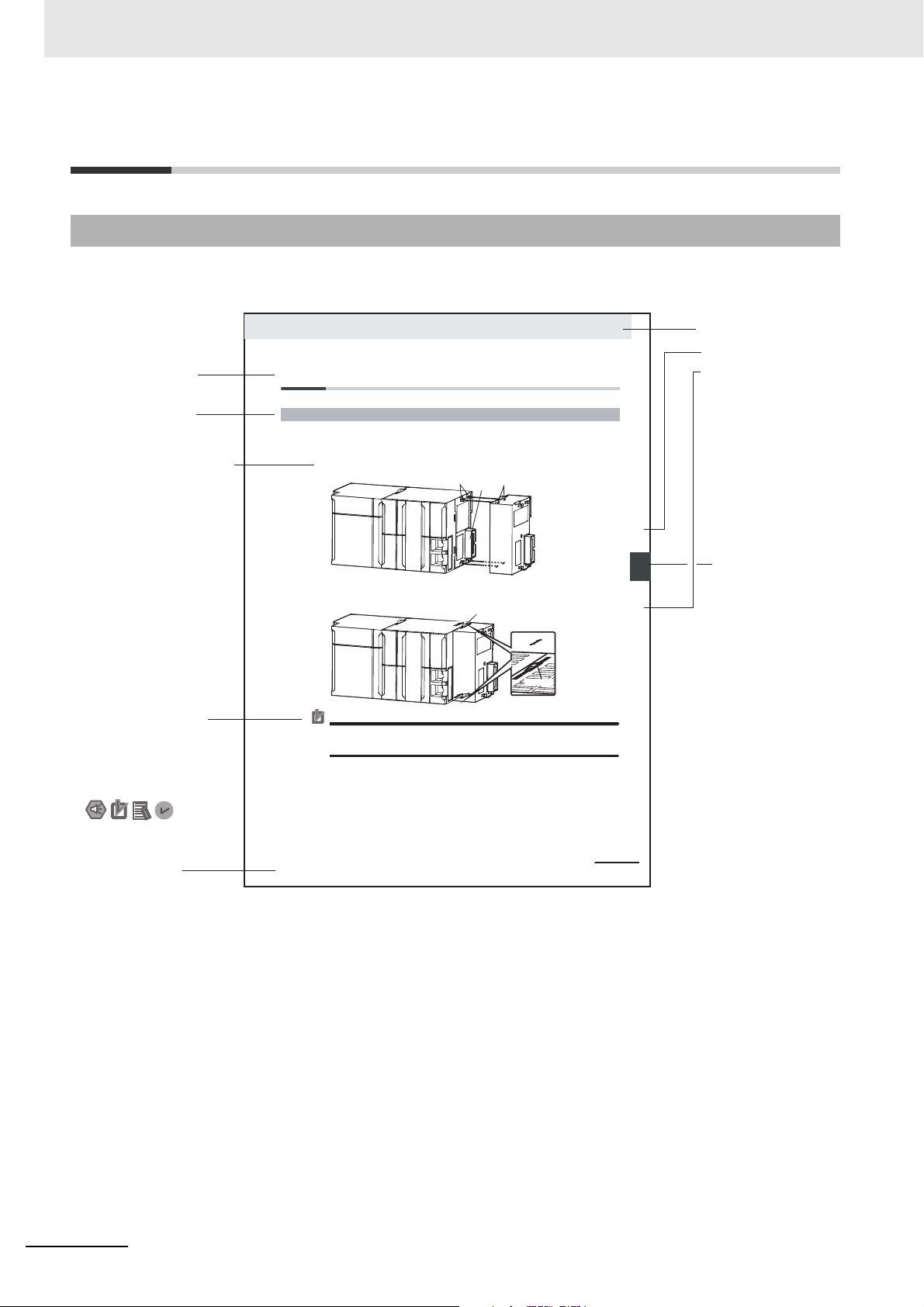
Manual Structure
4-9
4 Installation and Wiring
NJ-series CPU Unit Hardware User’s Manual (W500)
s
t
i
n
U
gnitn
u
oM
3-4
4
s
t
ne
no
p
m
o
C
rel
l
o
r
t
n
oC
g
n
i
tc
e
n
noC
1
-
3-
4
4-3 Mounting Units
The Units that make up an NJ-series Controller can be connected simply by pressing the Units together
and locking the sliders by moving them toward the back of the Units. The End Cover is connected in the
same way to the Unit on the far right side of the Controller.
1 Join the Units so that the connectors fit exactly.
2 The yellow sliders at the top and bottom of each Unit lock the Units together. Move the sliders
toward the back of the Units as shown below until they click into place.
Precautions for Correct UsePrecautions for Correct Use
4-3-1 Connecting Controller Components
Connector
Hook
Hook holes
Slider
Lock
Release
Move the sliders toward the back
until they lock into place.
Level 1 heading
Level 2 heading
Level 3 heading
Level 2 heading
A step in a procedure
Manual name
Special information
Level 3 heading
Page tab
Gives the current
headings.
Indicates a procedure.
Icons indicate
precautions, additional
information, or reference
information.
Gives the number
of the main section.
The sliders on the tops and bottoms of the Power Supply Unit, CPU Unit, I/O Units, Special I/O
Units, and CPU Bus Units must be completely locked (until they click into place) after connecting
the adjacent Unit connectors.
Manual Structure
Page Structure and Icons
The following page structure and icons are used in this manual.
Note This illustration is provided only as a sample. It may not literally appear in this manual.
10
NX-series EtherCAT Coupler Unit User’s Manual (W519)
Page 13
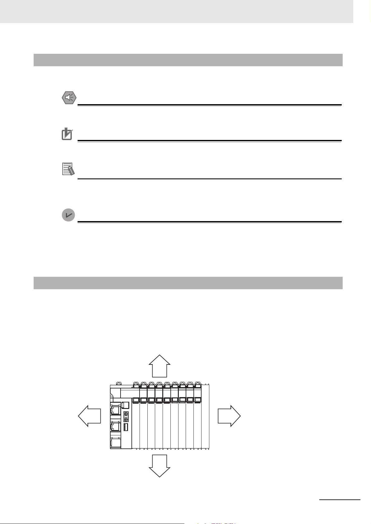
Precautions for Safe Use
Precautions for Correct Use
Additional Information
Version Information
Special Information
RightLeft
Up
Down
Special information in this manual is classified as follows:
Precautions on what to do and what not to do to ensure safe usage of the product.
Precautions on what to do and what not to do to ensure proper operation and performance.
Additional information to read as required.
This information is provided to increase understanding or make operation easier.
Manual Structure
Information on differences in specifications and functionality for CPU Units and EtherCAT Coupler Units with different unit versions and for different versions of the Sysmac Studio is given.
Note References are provided to more detailed or related information.
Precaution on Terminology
• In this manual, “download” refers to transferring data from the Sysmac Studio to the physical Controller and “upload” refers to transferring data from the physical Controller to the Sysmac Studio.
For the Sysmac Studio, synchronization is used to both upload and download data. Here, “synchronize” means to automatically compare the data for the Sysmac Studio on the computer with the data
in the physical Controller and transfer the data in the direction that is specified by the user.
• In this manual, the directions in relation to the Units are given in the following figure, which shows
upright installation.
NX-series EtherCAT Coupler Unit User’s Manual (W519)
11
Page 14

Read and Understand this Manual
Read and Understand this Manual
Please read and understand this manual before using the products. Please consult your OMRON
representative if you have any questions or comments.
Warranty and Limitations of Liability
WARRANTY
OMRON's exclusive warranty is that the products are free from defects in materials and workmanship for a
period of one year (or other period if specified) from date of sale by OMRON.
OMRON MAKES NO WARRANTY OR REPRESENTAT IO N, EXPRESS OR IMPLIED, REGARDING
NON-INFRINGEMENT, MERCHANTABILITY, OR FITNESS FOR PARTICULAR PURPOSE OF THE
PRODUCTS. ANY BUYER OR USER ACKNOWLEDGES THAT THE BUYER OR USER ALONE HAS
DETERMINED THAT THE PRODUCTS WILL SUITABLY MEET THE REQUIREMENTS OF THEIR
INTENDED USE. OMRON DISCLAIMS ALL OTHER WARRANTIES, EXPRESS OR IMPLIED.
LIMITATIONS OF LIABILITY
OMRON SHALL NOT BE RESPONSIBLE FOR SPECIAL, INDIRECT, OR CONSEQUENTIAL DAMAGES,
LOSS OF PROFITS OR COMMERCIAL LOSS IN ANY WAY C ONNECTED WITH THE PRODUCTS,
WHETHER SUCH CLAIM IS BASED ON CONTRACT, WARRANTY, NEGLIGENCE, OR STRICT
LIABILITY.
In no event shall the responsibility of OMRON for any act exceed the individual price of the product on which
liability is asserted.
IN NO EVENT SHALL OMRON BE RESPONSIBLE FOR WARRANTY, REPAIR, OR OTHER CLAIMS
REGARDING THE PRODUCTS UNLESS OMRON'S ANALYSIS CONFIRMS THAT THE PRODUCTS
WERE PROPERLY HANDLED, STORED, INSTALLED, AND MAINTA I NED AND NOT SUBJECT TO
CON
TA MI NATI O N, ABUSE, MISUSE, OR INAPPROPRIATE MODIFICATION OR REPAIR.
12
NX-series EtherCAT Coupler Unit User’s Manual (W519)
Page 15

Read and Understand this Manual
Application Considerations
SUITABILITY FOR USE
OMRON shall not be responsible for conformity with any standards, codes, or regulations that apply to the
combination of products in the customer's application or use of the products.
At the customer's request, OMRON will provide applicable third party certification documents identifying
ratings and limitations of use that apply to the products. This information by itself is not sufficient for a
complete determination of the suitability of the products in combination with the end product, machine,
system, or other application or use.
The following are some examples of applications for which particular attention must be given. This is not
intended to be an exhaustive list of all possible uses of the products, nor is it intended to imply that the uses
listed may be suitable for the products:
•Ou
tdoor use, uses involving potential chemical contamination or electrical interference, or conditions or
uses not described in this manual.
• Nuclear energy control systems, combustion systems, railroad systems, aviation systems, medical
equipment, amusement machines, vehicles, safety equipment, and installations subject to separate
industry or government regulations.
• Systems, machines, and equipment that could present a risk to life or property.
Please know and observe all prohibitions of use applicable to the products.
NEVER USE THE PRODUCTS FOR AN APPLICATION INVOLVING SERIOUS RISK TO LIFE OR
PROPERTY WITHOUT ENSURING THAT THE SYSTEM AS A WHOLE HAS BEEN DESIGNED TO
ADDRESS THE RISKS, AND THAT THE OMRON PRODUCTS ARE PROPERLY RATED AND INSTALLED
FOR THE INTENDED USE WITHIN THE OVERALL EQUIPME
NT OR SYSTEM.
PROGRAMMABLE PRODUCTS
OMRON shall not be responsible for the user's programming of a programmable product, or any
consequence thereof.
NX-series EtherCAT Coupler Unit User’s Manual (W519)
13
Page 16

Read and Understand this Manual
Disclaimers
CHANGE IN SPECIFICATIONS
Product specifications and accessories may be changed at any time based on improvements and other
reasons.
It is our practice to change model numbers when published ratings or features are changed, or when
significant construction changes are made. However, some specifications of the products may be changed
without any notice. When in doubt, special model numbers may be assigned to fix or establish key
specifications for your application on your request. Please consult with your OMRON representative at any
time to confirm actual specifications of purchased products.
DIMENSIONS AND WEIGHTS
Dimensions and weights are nominal and are not to be used for manufacturing purposes, even when
tolerances are shown.
PERFORMANCE DATA
Performance data given in this manual is provided as a guide for the user in determining suitability and does
not constitute a warranty. It may represent the result of OMRON's test conditions, and the users must
correlate it to actual application requirements. Actual performance is subject to the OMRON Warranty and
Limitations of Liability.
ERRORS AND OMISSIONS
The information in this manual has been carefully checked and is believed to be accurate; however, no
responsibility is assumed for clerical, typographical, or proofreading errors, or omissions.
14
NX-series EtherCAT Coupler Unit User’s Manual (W519)
Page 17
Safety Precautions
WARNING
Caution
Indicates a potentially hazardous situation which, if not avoided,
could result in death or serious injury. Additionally, there may be
severe property damage.
Indicates a potentially hazardous situation which, if not avoided,
may result in minor or moderate injury, or property damage.
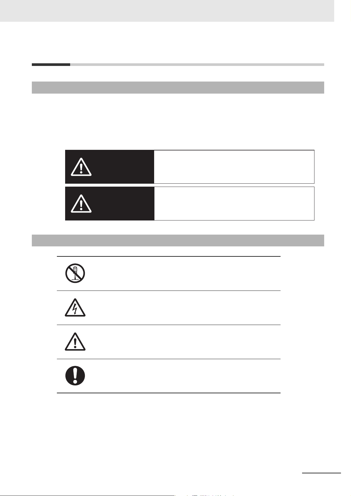
Definition of Precautionary Information
The following notation is used in this manual to provide precautions required to ensure safe usage of an
NX-series EtherCAT Coupler Unit.
The safety precautions that are provided are extremely important to safety. Always read and heed the
information provided in all safety precautions.
The following notation is used.
Safety Precautions
Symbols
The circle and slash symbol indicates operations that you must not do.
The specific operation is shown in the circle and explained in text.
This example indicates prohibiting disassembly.
The triangle symbol indicates precautions (including warnings).
The specific operation is shown in the triangle and explained in text.
This example indicates a precaution for electric shock.
The triangle symbol indicates precautions (including warnings).
The specific operation is shown in the triangle and explained in text.
This example indicates a general precaution.
The filled circle symbol indicates operations that you must do.
The specific operation is shown in the circle and explained in text.
This example shows a general precaution for something that you must do.
NX-series EtherCAT Coupler Unit User’s Manual (W519)
15
Page 18
Safety Precautions
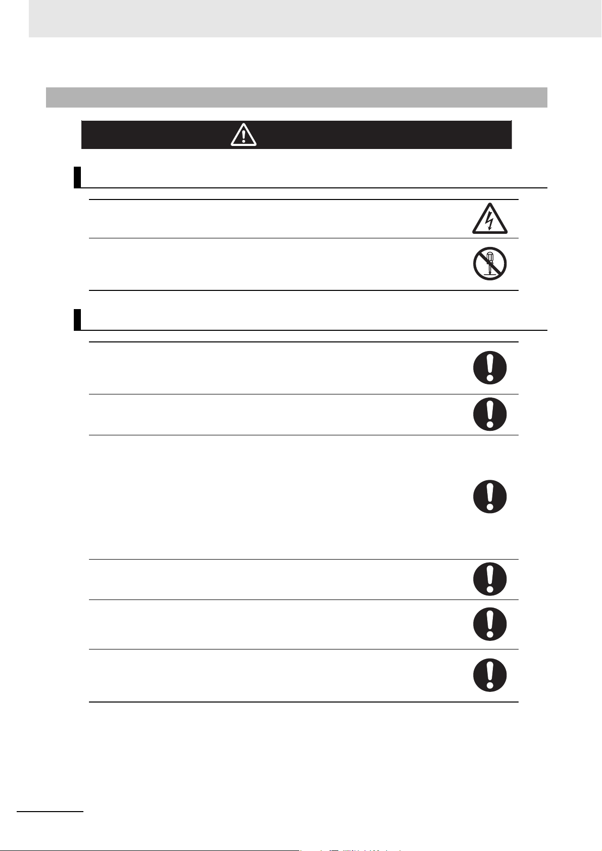
WARNING
Warnings
During Power Supply
Do not touch the terminal section while power is ON.
Electric shock may occur.
Do not attempt to take any Unit apart.
In particular, high-voltage parts are present in Units that supply power while power is supplied or immediately after power is turned OFF. Touching any of these parts may result in
electric shock. There are sharp parts inside the Unit that may cause injury.
Fail-safe Measures
Provide safety measures in external circuits to ensure safety in the system if an abnormality
occurs due to malfunction of the CPU Unit, other Units, or slaves or due to other external
factors affecting operation.
Not doing so may result in serious accidents due to incorrect operation.
Emergency stop circuits, interlock circuits, limit circuits, and similar safety measures must
be provided in external control circuits.
The CPU Unit will turn OFF all outputs from Basic Output Units in the following cases. The
remote I/O slaves will operate according to the settings in the slaves.
• If a power supply error occurs.
• If the power supply connection becomes faulty.
• If a CPU watchdog timer error or CPU reset occurs.
• If a Controller error in the major fault level occurs.
• While the CPU Unit is on standby until RUN mode is entered after the power is turned ON
External safety measures must be provided to ensure safe operation of the system in such
cases.
The outputs may remain ON or OFF due to deposition or burning of the output relays or
destruction of the output transistors. As a countermeasure for such problems, external
safety measures must be provided to ensure safe operation of the system.
If external power supplies for slaves or other devices are overloaded or short-circuited, the
voltage will drop, outputs will turn OFF, and the system may be unable to read inputs. Provide external safety measures in control with monitoring of external power supply voltage
as required so that the system operates safely in such a case.
You must take fail-safe measures to ensure safety in the event of incorrect, missing, or
abnormal signals caused by broken signal lines, momentary power interruptions, or other
causes.
Not doing so may result in serious accidents due to incorrect operation.
16
NX-series EtherCAT Coupler Unit User’s Manual (W519)
Page 19
Voltage and Current Inputs
Caution
Make sure that the voltages and currents that are input to the Units and slaves are within
the specified ranges.
Inputting voltages or currents that are outside of the specified ranges may cause accidents
or fire.
Transferring
Always confirm safety at the destination node before you transfer Unit configuration information, parameters, settings, or other data from tools such as the Sysmac Studio.
The devices or machines may operate unexpectedly, regardless of the operating mode of
the Controller.
Cautions
Safety Precautions
Wiring
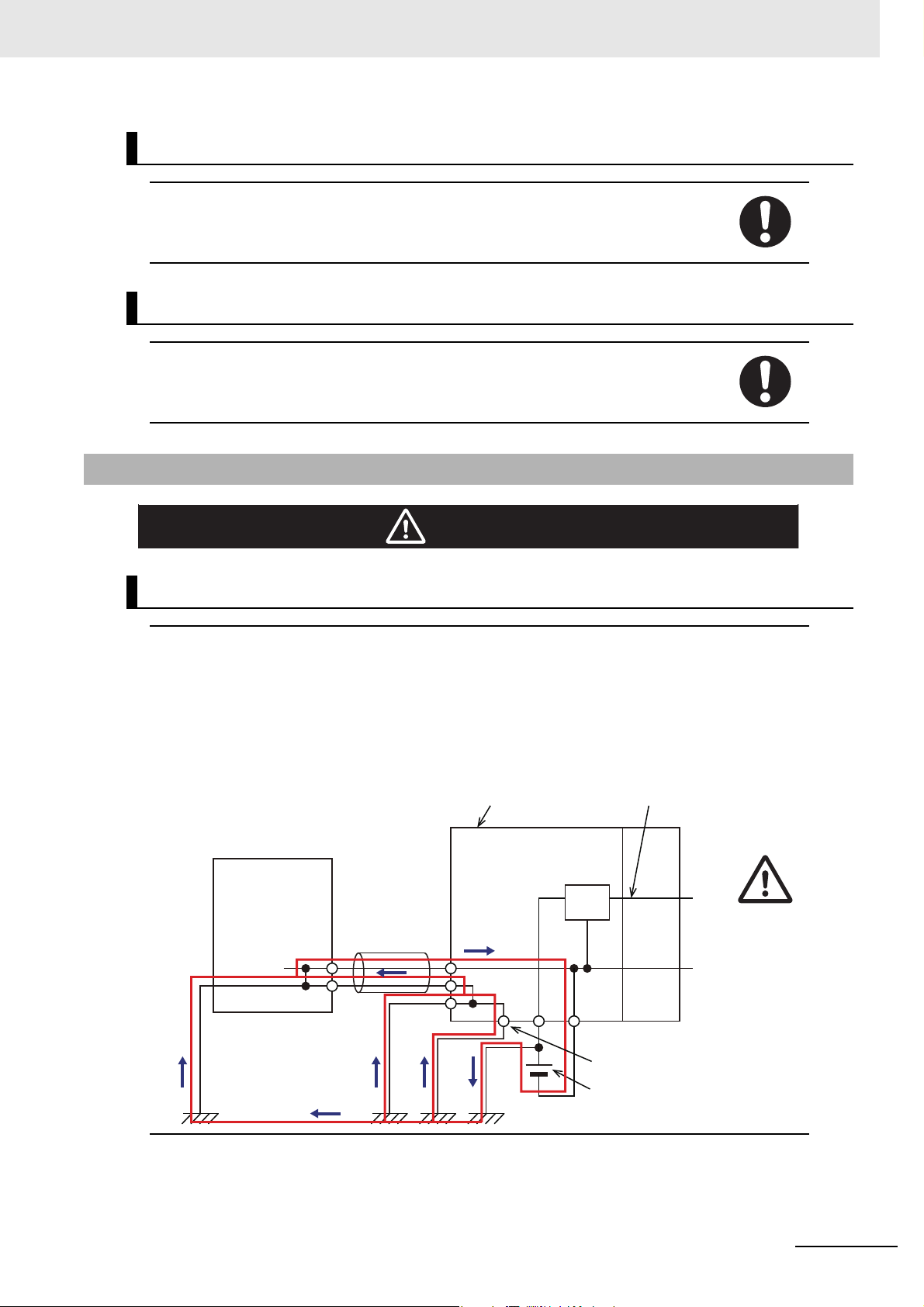
When you connect a computer or other peripheral device to a Communications Coupler
Unit that has a non-isolated DC power supply, either ground the 0-V side of the external
power supply (i.e. Unit power supply) or do not ground it at all.
If the peripheral devices are grounded incorrectly, the external power supply (i.e. Unit
power supply) may be short-circuited.
Never ground the 24-V side of the power supply, as shown in the following figure.
NX Unit power
supply
0 V
Peripheral device
(e.g., computer)
Communications Coupler Unit
Non-isolated DC power
supply (internal power
supply circuit)
Peripheral device
cable
24 V
NX-series EtherCAT Coupler Unit User’s Manual (W519)
Ground terminal
Unit power
supply
17
Page 20

Safety Precautions
Online Editing
Execute online editing only after confirming that no adverse effects will be caused by deviations in the timing of I/O. If you perform online editing, the task execution time may exceed
the task period, I/O may not be refreshed with external devices, input signals may not be
read, and output timing may change.
18
NX-series EtherCAT Coupler Unit User’s Manual (W519)
Page 21
Precautions for Safe Use
Up
Down
Transporting
• When transporting any Unit, use the special packing box for it.
Also, do not subject the Unit to excessive vibration or shock during transportation.
• Do not drop any Unit or subject it to abnormal vibration or shock.
Doing so may result in Unit malfunction or burning.
Mounting
• Mount terminal blocks and connectors only after checking the mounting location carefully.
• Be sure that the terminal blocks, expansion cables, and other items with locking devices are properly
locked into place.
Precautions for Safe Use
Installation
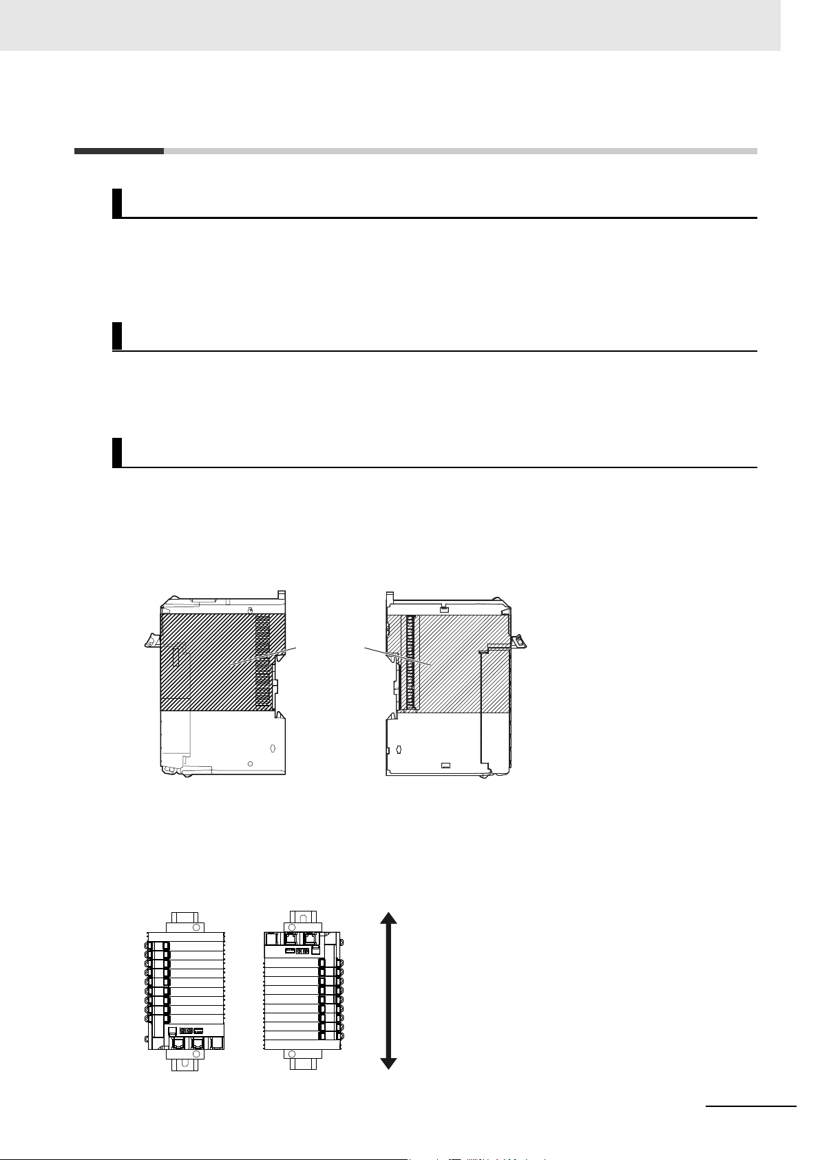
• Do not apply labels or tape to the Unit. When the Unit is installed or removed, adhesive or scraps
may adhere to the pins in the NX bus connector, which may result in malfunctions.
• Do not write on the Communications Coupler Unit or an NX Unit with ink within the restricted region
that is shown in the following figure. Also do not get this area dirty. When the Unit is installed or
removed, ink or dirt may adhere to the pins in the NX bus connector, which may result in malfunctions
in the Slave Terminal.
Restricted
region (shaded
portion)
Communications Coupler
Unit or NX Unit
• For the installation orientations in the following figure, support the cables, e.g., with a duct, so that the
End Plate on the bottom is not subjected to the weight of the cables. The weight of the cables may
cause the bottom End Plate to slide downward so that the Slave Terminal is no longer secured to the
DIN Track, which may result in malfunctions.
NX Unit
NX-series EtherCAT Coupler Unit User’s Manual (W519)
19
Page 22
Precautions for Safe Use
NG NG
Wiring
• Double-check all switches and other settings and double-check all wiring to make sure that they are
correct before turning ON the power supply.
Use the correct wiring parts and tools when you wire the system.
• Do not pull on the cables or bend the cables beyond their natural limit. Also, do not place heavy
objects on top of the cables or other wiring lines. Doing so may break the cable.
• When wiring or installing the Units, do not allow metal fragments to enter the Units.
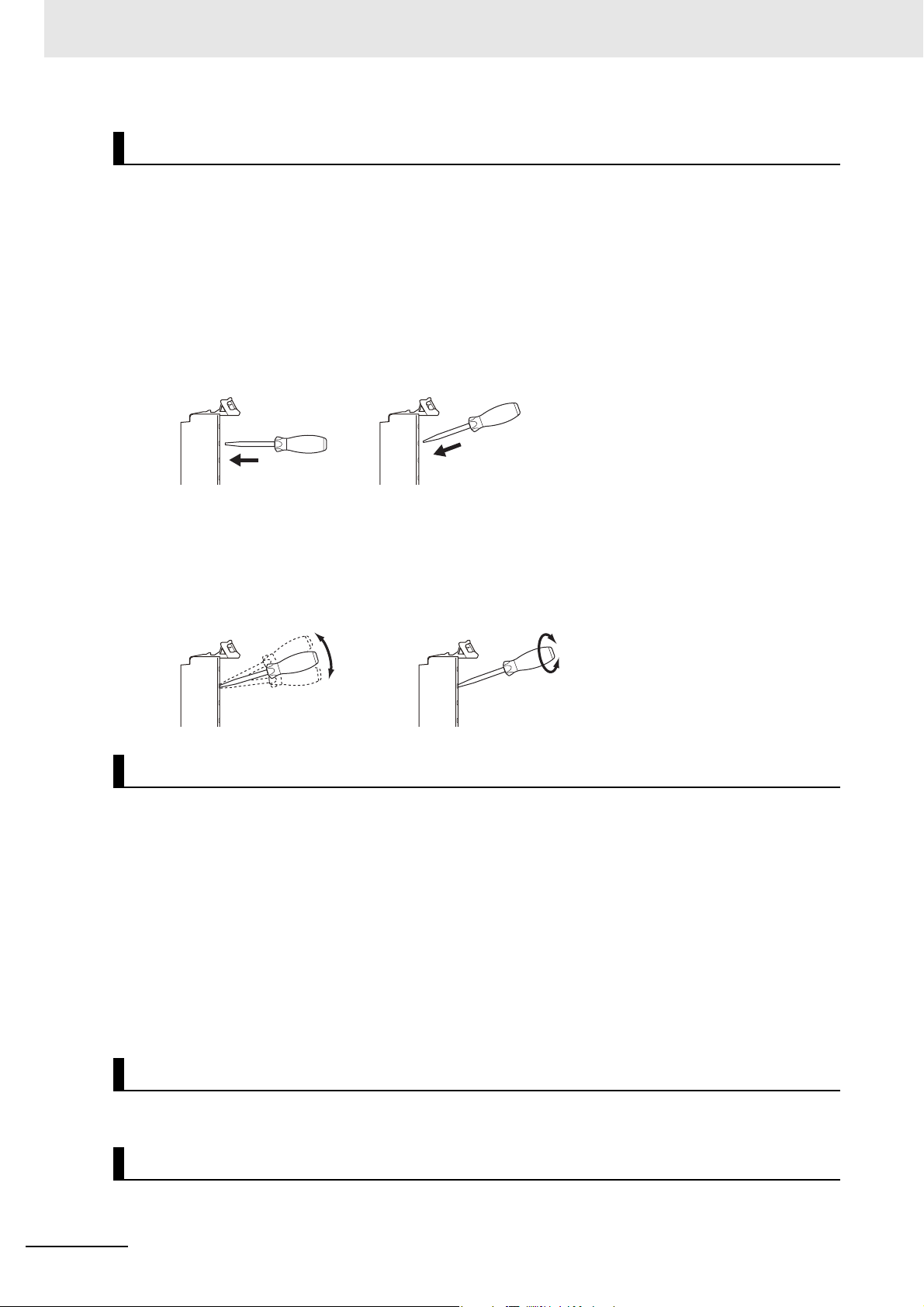
• Do not press the flat-blade screwdriver straight into the release holes on a screwless clamping terminal block. Doing so may damage the terminal block.
NG OK
• When you insert a flat-blade screwdriver into a release hole on a screwless clamping terminal block,
press it down with a force of 30N or less. Applying excessive force may damage the terminal block.
• Do not incline or twist the flat-blade screwdriver while it is in a release hole on a screwless clamping
terminal block. Doing so may damage the terminal block.
Power Supply Design
• Use all Units within the I/O power supply ranges that are given in the specifications.
• Supply sufficient power according to the contents of this manual.
• Use the power supply voltage that is specified in this manual.
• Do not apply voltages that exceed the rated value to any Input Unit.
• Do not apply voltages or connect loads to the Output Units or slaves in excess of the maximum ratings.
• Inrush current occurs when the power supply is turned ON. When selecting fuses or breakers for
external circuits, consider their fusing and detection characteristics as well as the above precautions
and allow sufficient margin in shut-off performance.
• Install external breakers and take other safety measures against short-circuiting and overcurrents in
external wiring.
Turning ON the Power Supply
• When you set the Operating Mode at Startup, confirm that no adverse effect will occur in the system.
Actual Operation
20
• Before you start operation, always register the NX Units that are connected to the Communications
Coupler Unit in the host communications master as the Unit Configuration Information.
NX-series EtherCAT Coupler Unit User’s Manual (W519)
Page 23

Precautions for Safe Use
• Check the user program, data, and parameter settings for proper execution before you use them for
actual operation.
Turning OFF the Power Supply
• Do not disconnect the cable or turn OFF the power supply to the Controller or a Slave Terminal when
downloading data or the user program from Sysmac Studio.
• Always turn OFF the external power supply to the Units before attempting any of the following.
Mounting or removing an NX Unit, Communications Coupler Unit, or CPU Unit
Assembling Units
Setting DIP switches or rotary switches
Connecting or wiring cables
Attaching or removing terminal blocks or connectors
Units that supply power continue to supply power to the Units for up to several seconds after the
power supply is turned OFF. The PWR indicator remains lit as long as power is supplied. Confirm that
the PWR indicator is not lit before you perform any of the above.
Operation
• Confirm that the controlled system will not be adversely affected before you perform any of the following operations.
Changing the operating mode of the CPU Unit (including changing the setting of the Operating
Mode at Startup)
Changing the user program or settings
Changing set values or present values
Forced refreshing
• Always sufficiently check the safety at the connected devices before you change the settings of an
EtherCAT slave or Special Unit.
General Communications
• Do not exceed the ranges that are given in the specifications for the communications distance and
number of connected Units.
EtherCAT Communications
• Make sure that the communications distance, number of nodes connected, and method of connection for EtherCAT are within specifications.
Do not connect EtherCAT Coupler Units to EtherNet/IP, a standard in-house LAN, or other networks.
An overload may cause the network to fail or malfunction.
• Malfunctions or unexpected operation may occur for some combinations of EtherCAT revisions of the
master and slaves. If you disable the revision check in the network settings, check the slave revision
settings in the master and the actual slave revisions, and then make sure that functionality is compatible in the manuals or other references. You can check the slave versions in the settings from the
Sysmac Studio and you can check the actual slave revisions from the Sysmac Studio or on slave
nameplates.
• After you transfer the user program, the CPU Unit is restarted and communications with the EtherCAT slaves are cut off. During that period, the slave outputs behave according to the slave settings.
The time that communications are cut off depends on the EtherCAT network configuration.
Before you transfer the user program, confirm that the system will not be adversely affected.
• EtherCAT communications are not always established immediately after the power supply is turned
ON. Use the system-defined variables in the user program to confirm that communications are established before attempting control operations.
NX-series EtherCAT Coupler Unit User’s Manual (W519)
21
Page 24

Precautions for Safe Use
• If frames sent to EtherCAT slaves are lost due to noise or other causes, slave I/O data is not communicated, and the intended operation is sometimes not achieved. Perform the following processing if
noise countermeasures are necessary.
Program the _EC_InDataInvalid (Input Data Disable) system-defined variable as an interlock condition in the user program.
Set the PDO communications consecutive timeout detection count setting in the EtherCAT master to
at least 2.
Refer to the NJ-series CPU Unit Built-in EtherCAT Port User’s Manual (Cat. No. W505) for details.
• When an EtherCAT slave is disconnected, communications will stop and control of the outputs will be
lost not only for the disconnected slave, but for all slaves connected after it. Confirm that the system
will not be adversely affected before you disconnect a slave.
• If you disconnect the cable from an EtherCAT slave to disconnect it from the network, any current
communications frames may be lost. If frames are lost, slave I/O data is not communicated, and the
intended operation is sometimes not achieved. Perform the following processing for a slave that
needs to be replaced.
Program the _EC_InDataInvalid (Input Data Disable) system-defined variable as an interlock condition in the user program.
Set the PDO communications consecutive timeout detection count setting in the EtherCAT master to
at least 2.
Refer to the NJ-series CPU Unit Built-in EtherCAT Port User’s Manual (Cat. No. W505) for details.
Unit Replacement
• When you replace a Unit, start operation only after you transfer the settings and variables that are
required for operation to the new Unit.
Disposal
• Dispose of the product according to local ordinances as they apply.
22
NX-series EtherCAT Coupler Unit User’s Manual (W519)
Page 25

Precautions for Correct Use
Storage, Mounting, and Wiring
• Follow the instructions in this manual to correctly perform installation.
• Do not operate or store the Units in the following locations. Operation may stop or malfunction may
occur.
Locations subject to direct sunlight
Locations subject to temperatures or humidity outside the range specified in the specifications
Locations subject to condensation as the result of severe changes in temperature
Locations subject to corrosive or flammable gases
Locations subject to dust (especially iron dust) or salts
Locations subject to exposure to water, oil, or chemicals
Locations subject to shock or vibration
• Take appropriate and sufficient countermeasures during installation in the following locations.
Locations subject to strong, high-frequency noise
Locations subject to static electricity or other forms of noise
Locations subject to strong electromagnetic fields
Locations subject to possible exposure to radioactivity
Locations close to power lines
• Before touching a Unit, be sure to first touch a grounded metallic object in order to discharge any
static build-up.
• Use the rated power supply voltage for the Units that supply power. Take appropriate measures to
ensure that the specified power with the rated voltage and frequency is supplied in places where the
power supply is unstable.
• Install the Units away from sources of heat and ensure proper ventilation. Not doing so may result in
malfunction, in operation stopping, or in burning.
• Do not allow foreign matter to enter the openings in the Unit. Doing so may result in Unit burning,
electric shock, or failure.
• Use the EtherCAT connection methods and applicable cables that are specified in this manual and in
the NJ-series CPU Unit Built-in EtherCAT Port User’s Manual (Cat. No. W505). Otherwise, communi-
cations may be faulty.
Precautions for Correct Use
Actual Operation
• If you change the event level of an error, the output status when the error occurs may also change.
Confirm safety before you change an event level.
Turning OFF the Power Supply
• Do not turn OFF the power supply while data is being transferred.
• Do not turn OFF the power supply while parameters are being written to the Communications Coupler Unit or NX Units.
EtherCAT Communications
• Do not disconnect the EtherCAT communications cables during operation. The outputs will become
unstable. However, for the built-in EtherCAT port on the NJ-series CPU Unit, it is OK to disconnect
the communications cable from an EtherCAT Slave Terminal that has been disconnected from communications in the software.
NX-series EtherCAT Coupler Unit User’s Manual (W519)
23
Page 26

Regulations and Standards
Regulations and Standards
Conformance to EC Directives
Applicable Directives
• EMC Directives
• Low Voltage Directive
Concepts
EMC Directives
OMRON devices that comply with EC Directives also conform to the related EMC standards so that
they can be more easily built into other devices or the overall machine. The actual products have
been checked for conformity to EMC standards.*1
Whether the products conform to the standards in the system used by the customer, however, must
be checked by the customer. EMC-related performance of the OMRON devices that comply with EC
Directives will vary depending on the configuration, wiring, and other conditions of the equipment or
control panel on which the OMRON devices are installed. The customer must, therefore, perform
the final check to confirm that devices and the overall machine conform to EMC standards.
*1. Applicable EMC (Electromagnetic Compatibility) standards are as follows:
EMS (Electromagnetic Susceptibility): EN 61131-2
EMI (Electromagnetic Interference): EN 61131-2 (Radiated emission: 10-m regulations).
Low Voltage Directive
Always ensure that devices operating at voltages of 50 to 1,000 VAC and 75 to 1,500 VDC meet the
required safety standards. The applicable directive is EN 61131-2.
Conformance to EC Directives
The NX-series Units comply with EC Directives. To ensure that the machine or device in which the
NX-series Units are used complies with EC Directives, the following precautions must be observed.
• The NX-series Units must be installed within a control panel.
• You must use reinforced insulation or double insulation for the DC power supplies that are connected as the Unit power supplies and I/O power supplies for the NX-series Units.
We recommend that you use the OMRON S8JX-series Power Supplies. EMC standard compliance was confirmed for the recommended Power Supplies.
• NX-series Units that comply with EC Directives also conform to the Common Emission Standard
(EN 61131-2). Radiated emission characteristics (10-m regulations) may vary depending on the
configuration of the control panel used, other devices connected to the control panel, wiring, and
other conditions.
You must therefore confirm that the overall machine or equipment in which the NX-series Units
are used complies with EC Directives.
• You must use power supplies with an output hold time of 10 ms or longer for the DC power supplies that are connected as the Unit power supplies and I/O power supplies for the NX-series
Units.
• This is a Class A product (for industrial environments). In a residential environment, it may cause
radio interference. If radio interference occurs, the user may be required to take appropriate measures.
24
NX-series EtherCAT Coupler Unit User’s Manual (W519)
Page 27

Conformance to UL and CSA Standards
The NX-series Units comply with the following UL and CSA standards. The application conditions for
standard compliance are defined. Refer to the Instruction Sheet that is provided with each Unit before
application.
Conformance to KC Standards
Observe the following precaution if you use NX-series Units in Korea.
Regulations and Standards
Class A Device (Broadcasting Communications Device for Office Use)
This device obtained EMC registration for office use (Class A), and it is intended to be used in places
other than homes.
Sellers and/or users need to take note of this.
Software Licenses and Copyrights
This product incorporates certain third party software. The license and copyright information associated
with this software is available at http://www.fa.omron.co.jp/nj_info_e/.
NX-series EtherCAT Coupler Unit User’s Manual (W519)
25
Page 28
Unit Versions
Notched
area
Unit
specifications
LOT No.
Unit version
Lot number
Unit model number
Lot number and unit version
Unit Versions
This section describes the notation that is used for unit versions, the confirmation method for unit versions, and the relationship between unit versions and Sysmac Studio versions.
Unit Versions
A “unit version” has been introduced to manage the Units in the NX Series according to differences in
functionality accompanying Unit upgrades.
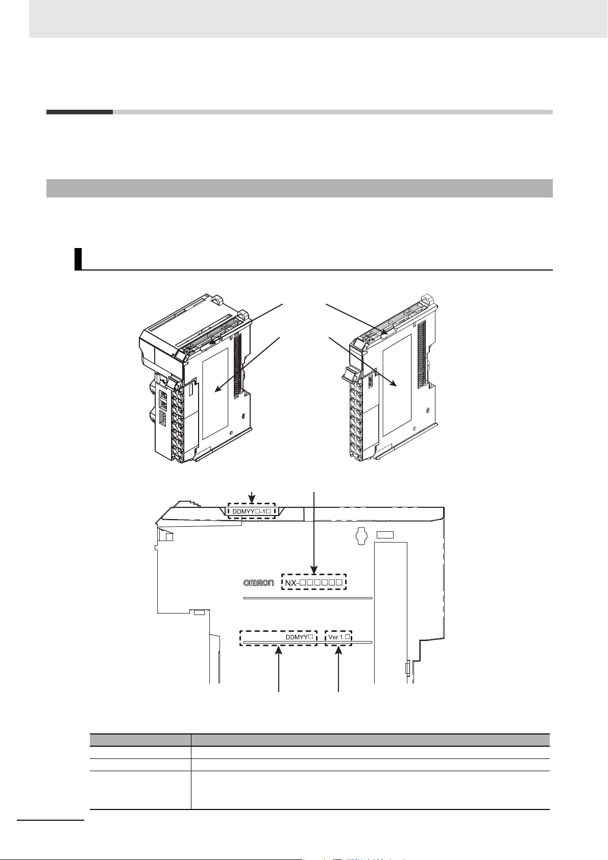
Notation of Unit Versions on Products
The unit version is given with the Unit specifications on the side of the Unit or in the notched area.
The following information is provided in the Unit specifications on the Unit.
Unit model number Gives the model of the Unit.
Unit version Gives the unit version of the Unit.
Lot number Gives the lot number of the Unit.
26
Name Function
DDMYY: Lot number, : Used by OMRON.
“M” gives the month (1 to 9: January to September, X: October, Y: November, Z: December)
NX-series EtherCAT Coupler Unit User’s Manual (W519)
Page 29
Unit Versions
The following information is provided in the notched area on the Unit.
Name Function
Lot number and
unit version
Gives the lot number and unit version of the Unit.
• DDMYY: Lot number, : Used by OMRON.
“M” gives the month (1 to 9: January to September, X: October, Y: November, Z: December)
•1: Unit version
The decimal portion of the unit version is omitted. (It is provided in the Unit specifications.)
Confirming Unit Versions with the Sysmac Studio
You can use the Unit Production Information on the Sysmac Studio to check the unit versions EtherCAT
Coupler Unit and NX Units.
1 Double-click EtherCAT under Configurations and Setup in the Multiview Explorer, and then
double-click the EtherCAT Coupler Unit. Or, right-click the EtherCAT Coupler Unit and select
Edit from the menu.
The Edit Slave Terminal Configuration Tab Page is displayed.
You can also display the Edit Slave Terminal Configuration Tab Page with any of the following
operations.
Double-click EtherCAT under Configurations and Setup in the Multiview Explorer, right-click
the EtherCAT Coupler Unit in the EtherCAT Configuration Edit Tab Page, and select Edit Slave
Terminal Configuration.
Or, select the EtherCAT Coupler Unit on the EtherCAT Configuration Edit Tab Page click the
Edit Slave Terminal Configuration Button.
2 Go online.
3 Right-click the EtherCAT Coupler Unit and select Display Production Information from the
menu.
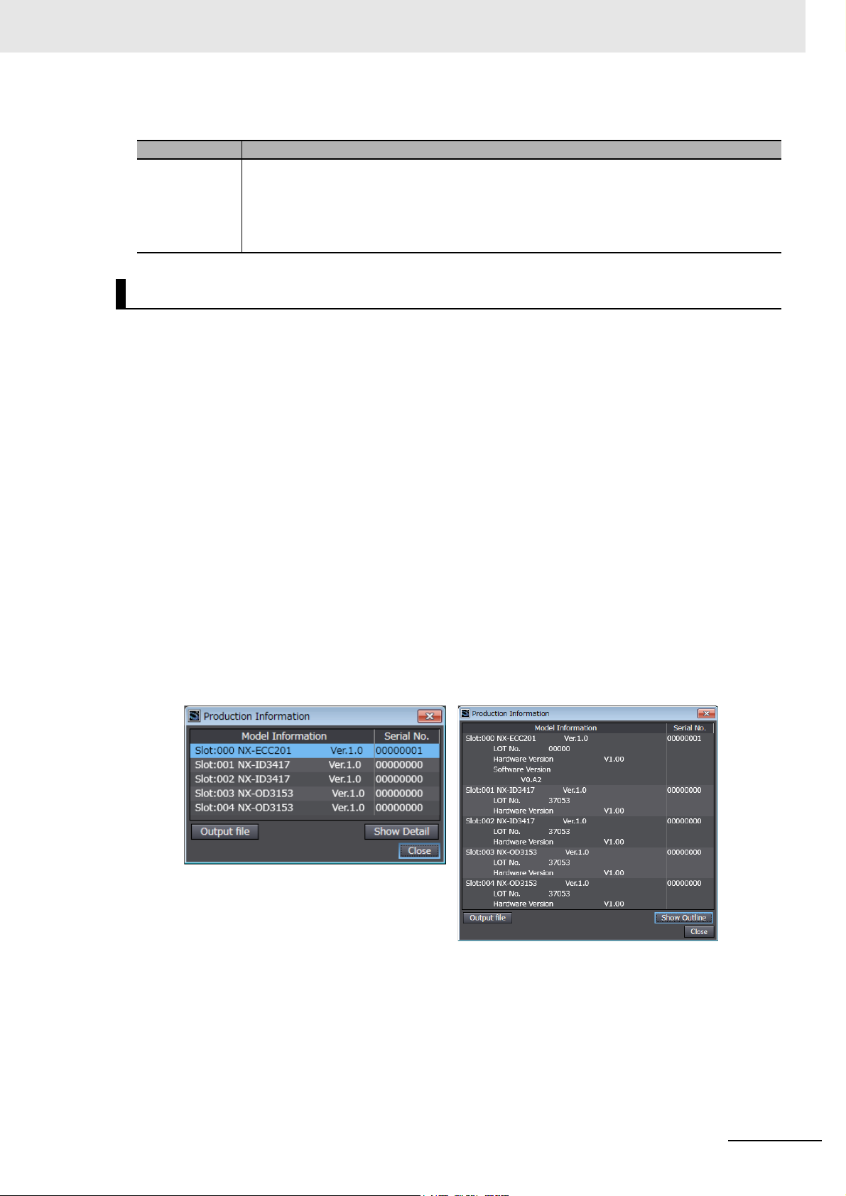
The Production Information Dialog Box is displayed.
Simple Display
In this example, “Ver.1.0” is displayed next to the Unit model.
The following items are displayed.
•Slot number
• Unit model number
•Unit version
• Serial number
• Lot number
NX-series EtherCAT Coupler Unit User’s Manual (W519)
Detailed Display
27
Page 30

Unit Versions
• Hardware version
• Software version
The software version is displayed only for Units that contain software.
Unit Versions and Sysmac Studio Versions
The functions that are supported depend on the unit version of the Unit. The version of Sysmac Studio
that supports the functions that were added for an upgrade is also required to use those functions.
Refer to A-7 Version Information on page A-59 for the functions that are supported by each unit version.
Unit Version Notation
In this User’s Manual, unit versions are specified as shown in the following table.
Unit version in Unit specifications
on the product
Unit version 1.0 or later Ver. 1. or later Unless unit versions are specified, the infor-
Notation in this manual Remarks
mation in this manual applies to all unit versions.
28
NX-series EtherCAT Coupler Unit User’s Manual (W519)
Page 31

Related Manuals
The following manuals are related to the NJ-series Controllers. Use these manuals for reference.
Manual name Cat. No. Model numbers Application Description
NX-series EtherCAT
Coupler Unit User’s
Manual (this manual)
NJ-series CPU Unit
Hardware User´s Manual
NJ-series CPU Unit
Software User's Manual
NJ-series CPU Unit
Built-in EtherCAT Port
User's Manual
NX-series Digital I/O
Units User’s Manual
W519 NX-ECC201 Leaning how to
use an NX-series
EtherCAT Coupler
Unit and EtherCAT Slave Terminals
W500 NJ501-
NJ301-
W501 NJ501-
NJ301-
W505 NJ501-
NJ301-
W521 NX-ID
NX-OC
NX-OD
Learning the basic
specifications of
the NJ-series CPU
Units, including
introductory information, designing,
installation, and
maintenance.
Mainly hardware
information is provided.
Learning how to
program and set
up an NJ-series
CPU Unit.
Mainly software
information is provided.
Using the built-in
EtherCAT port on
an NJ-series CPU
Unit.
Learning how to
use NX-series Digital I/O Units
The following items are described: the
overall system and configuration methods of an EtherCAT Slave Terminal
(which consists of an NX-series EtherCAT Coupler Unit and NX Units), and
information on hardware, setup, and
functions to set up, control, and monitor
NX Units through EtherCAT.
An introduction to the entire NJ-series
system is provided along with the following information on the CPU Unit.
• Features and system configuration
• Overview
• Part names and functions
• General specifications
• Installation and wiring
• Maintenance and Inspection
Use this manual together with the
NJ-series CPU Unit Software User's
Manual (Cat. No. W501).
The following information is provided
on an NJ-series CPU Unit.
• CPU Unit operation
• CPU Unit features
• Initial settings
• Programming based on IEC 61131-3
language specifications
Use this manual together with the
NJ-series CPU Unit Hardware User's
Manual (Cat. No. W500).
Information on the built-in EtherCAT
port is provided.
This manual provides an introduction
and provides information on the configuration, features, and setup.
Use this manual together with the
NJ-series CPU Unit Hardware User's
Manual (Cat. No. W500) and NJ-series
CPU Unit Software User's Manual (Cat.
No. W501).
The hardware, setup methods, and
functions of the NX-series Digital I/O
Units are described.
Related Manuals
NX-series EtherCAT Coupler Unit User’s Manual (W519)
29
Page 32

Related Manuals
Manual name Cat. No. Model numbers Application Description
NX-series Analog I/O
Units User’s Manual
NX-series System Units
User’s Manual
NX-series Position Interface Units User’s Manual
NX-series Data Reference Manual
NJ-series CPU Unit
Motion Control User's
Manual
NJ-series Instructions
Reference Manual
NJ-series Motion Control Instructions Reference Manual
Sysmac Studio Version
1 Operation Manual
W522 NX-AD
NX-DA
NX-TS
W523 NX-PD1
NX-PF0
NX-PC0
NX-TBX01
W524 NX-EC0
NX-ECS
NX-PG0
W525 NX- Referencing lists of
W507 NJ501-
NJ301-
W502 NJ501-
NJ301-
W508 NJ501-
NJ301-
W504 SYSMAC-
SE2
Learning how to
use NX-series
Analog I/O Units
and Temperature
Input Units
Learning how to
use NX-series
System Units
Learning how to
use NX-series
Position Interface
Units
the data that is
required to configure systems with
NX-series Units
Learning about
motion control settings and programming concepts.
Learning detailed
specifications on
the basic instructions of an
NJ-series CPU
Unit.
Learning about the
specifications of
the motion control
instructions.
Learning about the
operating procedures and functions of the
Sysmac Studio.
The hardware, setup methods, and
functions of the NX-series Analog I/O
Units and Temperature Input Units are
described.
The hardware and functions of the
NX-series System Units are described.
The hardware, setup methods, and
functions of the NX-series Incremental
Encoder Input Units, SSI Input Units,
and Pulse Output Unit are described.
Lists of the power consumptions,
weights, and other NX Unit data that is
required to configure systems with
NX-series Units are provided.
The settings and operation of the CPU
Unit and programming concepts for
motion control are described. When
programming, use this manual together
with the NJ-series CPU Unit Hardware
User's Manual (Cat. No. W500) and
NJ-series CPU Unit Software User's
Manual (Cat. No. W501).
The instructions in the instruction set
(IEC 61131-3 specifications) are
described.
When programming, use this manual
together with the NJ-series CPU Unit
Hardware User's Manual (Cat. No.
W500) and NJ-series CPU Unit Soft-
ware User's Manual (Cat. No. W501).
The motion control instructions are
described. When programming, use
this manual together with the NJ-series
CPU Unit Hardware User's Manual
(Cat. No. W500), NJ-series CPU Unit
Software User's Manual (Cat. No.
W501) and NJ-series CPU Unit Motion
Control User's Manual (Cat. No.
W507).
Describes the operating procedures of
the Sysmac Studio.
30
NX-series EtherCAT Coupler Unit User’s Manual (W519)
Page 33

Manual name Cat. No. Model numbers Application Description
NJ-series Troubleshooting Manual
W503 NJ501-
NJ301-
Learning about the
errors that may be
detected in an
NJ-series Controller.
Concepts on managing errors that may
be detected in an NJ-series Controller
and information on individual errors are
described.
Use this manual together with the
NJ-series CPU Unit Hardware User's
Manual (Cat. No. W500) and NJ-series
CPU Unit Software User's Manual (Cat.
No. W501).
Related Manuals
NX-series EtherCAT Coupler Unit User’s Manual (W519)
31
Page 34

Terminology
Terminology
Term
application layer status, AL status --- Status for indicating information on errors that occur in an application on
CAN application protocol over EtherCAT
CAN in Automation CiA CiA is the international users' and manufacturers' group that develops
Communications Coupler Units --- The generic name of an interface unit for remote I/O communications on
device profile --- A collection of device dependent information and functionality providing
device variable --- A variable in the NJ-series CPU Unit to which process data on an Ether-
distributed clock DC Clock distribution mechanism used to synchronize EtherCAT slaves and
EtherCAT slave controller ESC A controller for EtherCAT slave communications.
EtherCAT slave information ESI An XML file that contains setting information for an EtherCAT slave.
EtherCAT state machine ESM An EtherCAT communications state machine.
EtherCAT Technology Group ETG The ETG is a global organization in which OEM, end users, and technol-
I/O map settings --- Settings that assign variables to I/O ports. Assignment information
I/O port --- A logical interface that is used by the CPU Unit to exchange data with an
I/O refreshing --- Cyclic data exchange with external devices that is performed with prede-
index --- Address of an object within an application process.
network configuration information --- The EtherCAT network configuration information held by the EtherCAT
NX bus --- The NX-series internal bus.
object --- An abstract representation of a particular component within a device,
object dictionary OD Data structure that contains description of data type objects, communi-
Operational --- A state in EtherCAT communications where SDO communications and
PDO communications --- An acronym for process data communications.
Pre-Operational --- A state in EtherCAT communications where only SDO communications
primary periodic task --- The task with the highest priority.
process data --- Collection of application objects designated to be downloaded cyclically
process data communications --- One type of EtherCAT communications in which process data objects
process data object PDO A structure that describes the mappings of parameters that have one or
receive PDO RxPDO A process data object received by an EtherCAT slave.
Abbreviation
a slave.
CoE A CAN application protocol service implemented on EtherCAT.
and supports higher-layer protocols.
a network between NX Units and a host network master.
consistency between similar devices of the same device type.
CAT slave is allocated. Slave process data is accessed by directly reading and writing device variables from user applications on the NJ-series
CPU Unit.
the EtherCAT master.
ogy providers join forces to support and promote the further technology
development.
between I/O ports and variables.
external device (slave or Unit).
termined memory addresses.
master.
which consists of data, parameters, and methods.
cation objects and application objects.
I/O are possible.
are possible with the slaves, i.e., no I/O can be performed.
or acyclically for the purpose of measurement and control.
(PDOs) are used to exchange information cyclically and in realtime. This
is also called PDO communications.
more process data entities.
Description
32
NX-series EtherCAT Coupler Unit User’s Manual (W519)
Page 35

Terminology
Term
Safe-Operational --- A state in EtherCAT communications where only SDO communications
SDO communications --- One type of EtherCAT communications in which service data objects
service data object SDO CoE asynchronous mailbox communications where all objects in the
Slave Information Interface SII Slave information that is stored in non-volatile memory in the slave.
Slave Terminal --- A building-block remote I/O terminal to which a Communications Cou-
subindex --- Sub-address of an object within the object dictionary.
Sync Manager SM Collection of control elements to coordinate access to concurrently used
task period --- The interval at which the primary periodic task or a periodic task is exe-
transmit PDO TxPDO A process data object sent from an EtherCAT slave.
Abbreviation
Description
and reading input data from slaves are possible. Outputs from slaves are
not performed.
(SDOs) are used to transmit information whenever required.
object dictionary can be read and written.
pler Unit and NX Units are mounted
objects.
cuted.
NX-series EtherCAT Coupler Unit User’s Manual (W519)
33
Page 36

Revision History
Cat. No.
W519-E1-01
Revision code
Revision History
A manual revision code appears as a suffix to the catalog number on the front and back covers of the
manual.
Revision code Date Revised content
01 April 2013 Original production
34
NX-series EtherCAT Coupler Unit User’s Manual (W519)
Page 37

1
10
2
11
3
12
4
13
5
6
7
8
9
1
10
2
11
3
12
13
14
A
4
I
5
6
7
8
9
14
EtherCAT Networks
Features and System
Configuration
EtherCAT Coupler Unit
Functions
I/O Refreshing
Specifications and
Application Procedures
Communications
Performance
Part Names and
Functions
Troubleshooting
I
Index
Designing the Power
Supply System
Maintenance and
Inspection
A
Appendices
Wiring
Installation
EtherCAT Communications
Setting Up Slave Terminals
Sections in this Manual
Sections in this Manual
NX-series EtherCAT Coupler Unit User’s Manual (W519)
35
Page 38

Sections in this Manual
36
NX-series EtherCAT Coupler Unit User’s Manual (W519)
Page 39

EtherCAT Networks
This section provides an introduction to EtherCAT networks.
1-1 Introduction to EtherCAT . . . . . . . . . . . . . . . . . . . . . . . . . . . . . . . . . . . . . . . 1-2
1-1-1 How EtherCAT Works . . . . . . . . . . . . . . . . . . . . . . . . . . . . . . . . . . . . . . . . . . . . 1-2
1-1-2 Types of EtherCAT Communications . . . . . . . . . . . . . . . . . . . . . . . . . . . . . . . . 1-4
1-2 EtherCAT Network Configuration Elements . . . . . . . . . . . . . . . . . . . . . . . . 1-5
1-2-1 System Configuration Example of an EtherCAT Network . . . . . . . . . . . . . . . . . 1-5
1-2-2 Introduction to Configuration Devices . . . . . . . . . . . . . . . . . . . . . . . . . . . . . . . . 1-6
1
NX-series EtherCAT Coupler Unit User’s Manual (W519)
1 - 1
Page 40

1 EtherCAT Networks
EtherCAT master
Slave Slave
Slave
Ethernet frames
IN
OUT
Data
•
The slave reads output data addressed to it.
•
The slave writes input data.
1-1 Introduction to EtherCAT
EtherCAT (Ethernet Control Automation Technology) is a high-performance industrial network system
that enables faster and more efficient communications based on Ethernet.
Each node achieves a short communications cycle time by transmitting Ethernet frames at high speed.
Although EtherCAT is a unique communications protocol, standard Ethernet technology is used for the
physical layer, which means you can use Ethernet cables for wider application.
And the effectiveness of EtherCAT can be fully utilized not only in large control systems that require
high processing speeds and system integrity, but also in small and medium control systems.
1-1-1 How EtherCAT Works
With EtherCAT, Ethernet frames pass through all of the slave nodes.
When a frame passes through a slave node, the slave node reads and writes the data in the area that is
allocated to it in the frame in a few nanoseconds.
The Ethernet frames that are transmitted by the EtherCAT master pass through all EtherCAT slaves
without stopping. The last slave returns all of the frames, which again pass through all of the slaves
before returning to the EtherCAT master.
This mechanism ensures high speed and realtime data transmission.
1 - 2
NX-series EtherCAT Coupler Unit User’s Manual (W519)
Page 41

1 EtherCAT Networks
Ethernet
header
CRC
Ethernet data (1,498 bytes max.)
Data
Telegram
header
WKC
1st to nth EtherCAT telegrams
EtherCAT
header
1st EtherCAT
telegram
2nd EtherCAT
telegram
nth EtherCAT
telegram
. . . . .
EtherCAT frame
Ethernet frame
WKC: Working counter
The data exchanges that are cyclically performed between the EtherCAT master and EtherCAT slaves
use EtherCAT telegrams that are stored directly in the Ethernet frames.
Each EtherCAT telegram consists of a telegram header (including the data length and one or more
slave addresses), data, and a working counter (i.e., check bits).
If you think of an Ethernet frame as a train, the EtherCAT telegrams would be the cars of the train.
1-1 Introduction to EtherCAT
1
1-1-1 How EtherCAT Works
NX-series EtherCAT Coupler Unit User’s Manual (W519)
1 - 3
Page 42

1 EtherCAT Networks
EtherCAT master
Slave
Ethernet frame
Slave Slave
Slave
Ethernet
header
Ether
CAT
header
1st EtherCAT
telegram
2nd EtherCAT
telegram
3rd EtherCAT
telegram
CRC
Logical process data
Data a
Data b
Data c
1-1-2 Types of EtherCAT Communications
The following 2 types of communications are available with EtherCAT.
PDO communications are executed in each EtherCAT communications cycle to refresh data continuously. SDO communications are executed between PDO communications.
Process Data Communications (PDO Communications)
PDO communications transfers process data cyclically and in realtime.
The EtherCAT master maps the logical process data space to the nodes to achieve cyclic communications between the EtherCAT master and slaves.
Mailbox Communications (SDO Communications)
SDO communications is used to perform message communications.
Whenever necessary, the EtherCAT master sends a command to a slave, and then the slave returns a
response to the EtherCAT master.
The following data communications can be performed.
• Reading and writing process data
• Setting slaves
• Monitoring slave status
1 - 4
NX-series EtherCAT Coupler Unit User’s Manual (W519)
Page 43

1 EtherCAT Networks
1-2 EtherCAT Network Configu-
1-2 EtherCAT Network Configuration Ele-
ments
This section describes the devices that configure EtherCAT networks and the usage of those devices.
1-2-1 System Configuration Example of an EtherCAT Network
This section provides a system configuration example of an EtherCAT network.
Sysmac Studio
NJ-series CPU Unit
ESI files
EtherCAT master
ration Elements
1
1-2-1 System Configuration Example of an EtherCAT Network
Input port
EtherCAT Junction Slave
Output ports
I/O power supply
ADR
Servo Drive (EtherCAT slave) Inverter (EtherCAT slave)
Built-in EtherCAT port
Communications cable
EtherCAT Slave
Terminal
(EtherCAT slave)
ADR
Unit power supply
EtherCAT Junction Slave
Digital I/O Slave
(EtherCAT Slave)
ADR
Analog I/O Slave
(EtherCAT slave)
NX-series EtherCAT Coupler Unit User’s Manual (W519)
1 - 5
Page 44

1 EtherCAT Networks
1-2-2 Introduction to Configuration Devices
This section introduces the configuration devices.
EtherCAT Master
The EtherCAT master manages the network, monitors the status of the slaves, and exchanges I/O data
with the slaves.
EtherCAT Slaves
The EtherCAT slaves output the output data that is received from the EtherCAT master through the
EtherCAT network. They also send input data to the EtherCAT master through the EtherCAT network.
EtherCAT Slave Terminals
An EtherCAT Slave Terminal is a building-block slave that is created by mounting a group of NX Units to
an EtherCAT Coupler Unit.
EtherCAT Coupler Units
An EtherCAT Coupler Unit is a Communications Coupler Unit that connects NX Units to an EtherCAT network.
NX Units
The NX Units perform process data communications with the EtherCAT master through the EtherCAT Coupler Unit.
Refer to Section 2 Features and System Configuration for details on the features and system configuration of an EtherCAT Slave Terminal.
EtherCAT Junction Slaves
A Junction Slave is used only to branch EtherCAT network wiring.
1 - 6
Sysmac Studio
The Sysmac Studio runs on a personal computer and it is used to configure EtherCAT networks and
slaves, and to perform programming, monitoring, and troubleshooting.
Communications Cables
Use double-shielded cables with aluminum tape and braiding of Ethernet category 5 (100BASE-TX) or
higher, and use straight wiring.
ESI (EtherCAT Slave Information) Files
The ESI files contain information that is unique to the EtherCAT slaves in XML format.
NX-series EtherCAT Coupler Unit User’s Manual (W519)
Page 45

1 EtherCAT Networks
You can load an ESI file into the Sysmac Studio to easily allocate slave process data and make other
settings.
The ESI files for OMRON EtherCAT slaves are already installed in the Sysmac Studio.
You can update the Sysmac Studio to get the ESI files for the most recent models.
Unit Power Supplies
1-2 EtherCAT Network Configu-
ration Elements
Unit power supplies provide power for communications and the internal operation of EtherCAT Slave
Te rm i na l s.
I/O Power Supplies
I/O power supplies provide power for the I/O operation of the external devices that are connected to
EtherCAT Slave Terminals.
1
1-2-2 Introduction to Configuration Devices
NX-series EtherCAT Coupler Unit User’s Manual (W519)
1 - 7
Page 46

1 EtherCAT Networks
1 - 8
NX-series EtherCAT Coupler Unit User’s Manual (W519)
Page 47

4
Features and System Configuration
This section describes the features and system configurations of EtherCAT Slave Terminals.
2-1 Features of EtherCAT Slave Terminals . . . . . . . . . . . . . . . . . . . . . . . . . . . . 2-2
2-2 System Configurations of EtherCAT Slave Terminals . . . . . . . . . . . . . . . . 2-4
2-2-1 System Configuration . . . . . . . . . . . . . . . . . . . . . . . . . . . . . . . . . . . . . . . . . . . . 2-4
2-2-2 Types of NX Units . . . . . . . . . . . . . . . . . . . . . . . . . . . . . . . . . . . . . . . . . . . . . . . 2-6
2-3 Support Software . . . . . . . . . . . . . . . . . . . . . . . . . . . . . . . . . . . . . . . . . . . . . . 2-7
2-3-1 Applicable Support Software . . . . . . . . . . . . . . . . . . . . . . . . . . . . . . . . . . . . . . . 2-7
2-3-2 Connection Method and Procedures . . . . . . . . . . . . . . . . . . . . . . . . . . . . . . . . 2-7
2-3-3 Scope of Access When Connected to the USB Port on the EtherCAT
Coupler Unit . . . . . . . . . . . . . . . . . . . . . . . . . . . . . . . . . . . . . . . . . . . . . . . . . . . . . . . 2-9
2
NX-series EtherCAT Coupler Unit User’s Manual (W519)
2 - 1
Page 48

2 Features and System Configuration
2-1 Features of EtherCAT Slave Termi-
nals
An EtherCAT Slave Terminal is a building-block EtherCAT slave that is created by mounting a group of
NX Units to an EtherCAT Coupler Unit.
The NX Units can be flexibly combined with an EtherCAT Coupler Unit to achieve the optimum EtherCAT slave for the application with less wiring, less work, and less space.
The features of the EtherCAT Slave Terminals are described below.
Optimum Functionality and Ease of Operation Based on Unified
Specifications
The EtherCAT Coupler Unit is designed with the same communications and user interface specifications as other Sysmac devices. This provides optimum functionality and ease of operation when
used together with NJ-series Machine Automation Controllers and the Sysmac Studio Automation
Software.
The Entire System Provides Extremely Accurate Synchronized Control
When the EtherCAT Coupler Unit is used together with NX Units that support synchronous I/O
refreshing, all I/O refreshing is synchronized with the task period of the primary period of the
NJ-series CPU Unit. This provides an even higher level of synchronized control accuracy because it
suppresses jitter in the I/O response of the overall system.
This allows you to achieve the following control performance.
• Multiple Digital Input Units that support synchronous input refreshing process their inputs simultaneously, which improves the control accuracy of the system.
• Multiple Digital Output Units that support synchronous output refreshing process their outputs
simultaneously. This allows the outputs to refresh output devices in multiple locations at the same
time.
2 - 2
NX-series EtherCAT Coupler Unit User’s Manual (W519)
Page 49

2 Features and System Configuration
Features That Reduce Equipment Design Work and Commissioning
Work, and Encourage Modular Equipment Design
Registering NX Units in the Unit Configuration Information as Unmounted
Units for Future Expansion (Designing, Commissioning, and Modularity)
You can register any NX Units as unmounted Units in the Unit configuration information. This allows
the following possibilities.
• NX Units for future expansion can be registered in advance. This eliminates the need to change
the user program when the NX Units are actually added. (Designing)
• If certain NX Units are temporarily unavailable, you can still debug the system in advance with the
NX Units that are available. (Commissioning)
• Even if the number of NX Units changes depending on the type of equipment, the user program
does not have to be changed. (Designing and Modularity)
Exporting/importing Slave Terminal Settings and NX Unit Settings (Design-
ing)
2-1 Features of EtherCAT Slave Terminals
2
You can use the Sysmac Studio to export and import the EtherCAT Slave Terminal settings and NX
Unit settings as files. This allows you to reuse settings from an EtherCAT Slave Terminal or NX Units
for other EtherCAT Slave Terminals or NX Units.
Simplified I/O Wiring with Screwless Clamping Terminal Blocks (Commis-
sioning)
The EtherCAT Coupler Unit and the NX Units use screwless clamping terminal blocks. The use of
ferrules makes wiring an easy matter of inserting them. The screwless design greatly reduces wiring
work.
Support for Event Logs and Troubleshooting (Commissioning )
The EtherCAT Coupler Unit and the NX Units support the event logs in the NJ-series CPU Unit and
troubleshooting on the Sysmac Studio. This gives the event codes which allow you to determine the
cause of errors, and reduce the recovery work when an error occurs.
Back up, Restore, and Compare Data with SD Memory Cards and the Sysmac
Studio (Commissioning)
You can back up, restore, and compare EtherCAT Slave Terminal settings to data on an SD Memory
Card inserted in the NJ-series CPU Unit, or a specified memory device on the computer.
This allows you to reduce the recovery time when an error occurs in the equipment.
NX-series EtherCAT Coupler Unit User’s Manual (W519)
2 - 3
Page 50

2 Features and System Configuration
(A) EtherCAT master
NJ-series CPU Unit or master from another manufacturer
(G) Communications cable
Ethernet cables
(B) NX Series
EtherCAT Coupler Unit
NX-ECC201
(E) Sysmac Studio
Support Software
(E) Sysmac Studio
Support Software
(F) ESI files
(D) End Cover
(C) NX Units
Built-in EtherCAT port
(F) ESI files
Peripheral USB port
.xml
.xml
Connection to peripheral USB port
or built-in EtherNet/IP port on
NJ-series CPU Unit
Connection to peripheral USB
port on EtherCAT Coupler Unit
EtherCAT Slave Terminal
2-2 System Configurations of EtherCAT
Slave Terminals
This section describes the system configuration of an EtherCAT Slave Terminal.
2-2-1 System Configuration
An example of a system configuration for an EtherCAT Slave Terminal is shown below.
2 - 4
NX-series EtherCAT Coupler Unit User’s Manual (W519)
Page 51

2 Features and System Configuration
2-2 System Configurations of EtherCAT
Let-
ter
(A)
EtherCAT master
(B) EtherCAT Coupler
Unit
(C) NX Units The NX Units perform I/O processing with connected external devices. The NX
(D) End Cover The End Cover is attached to the end of the Slave Terminal.
(E) Sysmac Studio Sup-
port Software
(F) ESI (EtherCAT
Slave Information)
file
(G) Communications
cable
*1. A CPU Unit with unit version 1.05 or later is required to connect an EtherCAT Slave Terminal to the built-in
EtherCAT port on an OMRON NJ-series CPU Unit. Refer to A-7-2 Relationship between Unit Versions of
EtherCAT Coupler Unit and CPU Units on page A-59 for details. OMRON CJ1W-NC81/82 Position Control
Units cannot be connected to the EtherCAT Slave Terminal even though they support EtherCAT.
*2. Version 1.06 or higher of the Sysmac Studio is required to set up an EtherCAT Slave Terminal. Refer to A-7-1
Relationship between the Unit Versions of EtherCAT Coupler Unit and Sysmac Studio Versions on page A-59
for details.
Item Description
*1
The EtherCAT master manages the EtherCAT network, monitors the status of the
slaves, and exchanges I/O data with the slaves.
The EtherCAT Coupler Unit is an interface that performs process data communications between a group of NX Units and the EtherCAT master over an EtherCAT
network.
The I/O data for the NX Units is first accumulated in the EtherCAT Coupler Unit
and then all of the data is exchanged with the EtherCAT master at the same time.
The EtherCAT Coupler Unit can also perform message communications (SDO
communications) with the EtherCAT master.
You can connect up to 63 NX Units.
Units perform process data communications with the EtherCAT master through
the EtherCAT Coupler Unit.
Refer to 2-2-2 Types of NX Units on page 2-6 for the types of NX Units.
The Sysmac Studio runs on a personal computer and it is used to configure the
*2
EtherCAT network and EtherCAT Slave Terminals, and to perform programming,
monitoring, and troubleshooting.
You can connect the computer in which the Sysmac Studio is installed to the
peripheral USB port or built-in EtherNet/IP port on an NJ-series CPU Unit. Or you
can connect it to the peripheral USB port on the EtherCAT Coupler Unit to set up
the EtherCAT Slave Terminal.
Refer to 2-3 Support Software on page 2-7 for the connection procedure.
The ESI file contains information that is unique to the EtherCAT Slave Terminal in
XML format. You can load the ESI file into the Sysmac Studio to easily allocate
Slave Terminal process data and make other settings.
The ESI files for OMRON EtherCAT slaves are already installed in the Sysmac
Studio. You can update the Sysmac Studio to get the ESI files for the most recent
models.
Use a double-shielded cable with aluminum tape and braiding of category 5
(100BASE-TX) or higher, and use straight wiring.
Slave Terminals
2
2-2-1 System Configuration
NX-series EtherCAT Coupler Unit User’s Manual (W519)
2 - 5
Page 52

2 Features and System Configuration
2-2-2 Types of NX Units
The following table lists some examples of the types of NX Units that are available.
Unit type Overview
Digital I/O Units These Units process I/O with digital signals.
Digital Input Units These Units process inputs with digital signals.
Digital Output Units These Units process outputs with digital signals.
Analog I/O Units These Units process I/O with analog signals.
Analog Input Units These Units process inputs with analog signals.
Analog Output Units These Units process outputs with analog signals.
Temperature Input Units These Units process inputs from temperature sensors.
System Units System Units are used as required to build a Slave Terminal.
Additional NX Unit Power
Supply Unit
Additional I/O Power Supply Unit
I/O Power Supply Connection Unit
Shield Connection Unit This Unit is used to ground more than one shield wire from
Position Interface Units These Units perform I/O processing of position data for posi-
Incremental Encoder Input
Units
SSI Input Units These Units process serial signal inputs from absolute
Pulse Output Unit This Unit outputs pulses for positioning commands to a step-
Refer to the user’s manual for the specific Units for details.
This Unit is used when the NX Unit power supply is not sufficient.
This Unit is used when the I/O power supply is not sufficient
or to separate the power supply in the Slave Terminal.
This Unit is used when the I/O power supply terminals for
connections to external I/O devices are not sufficient.
external I/O connections to the same ground.
tioning.
These Units count pulses from incremental encoders.
encoders or linear scales that have an SSI interface.
per motor driver or other motor drive with a pulse input.
For information on the most recent lineup of NX Units, refer to NX-series catalogs or OMRON websites,
or ask your OMRON representative.
2 - 6
NX-series EtherCAT Coupler Unit User’s Manual (W519)
Page 53

2-3 Support Software
This section describes the Support Software that is used to set up the EtherCAT Slave Terminal.
2-3-1 Applicable Support Software
This following Support Software can be used to set up the EtherCAT Slave Terminal.
Support Software Vers ion
Sysmac Studio 1.06 or higher
2 Features and System Configuration
2-3 Support Software
2
2-3-2 Connection Method and Procedures
This section describes the methods and procedures that are used to connect the Sysmac Studio to an
EtherCAT Slave Terminal.
Going Online with the NJ-series CPU Unit
Connection Methods
You can place the Sysmac Studio online with the EtherCAT Slave Terminal through the CPU Unit.
There are the following four methods that you can use, based on the connection configuration, to
place the Sysmac Studio online with the NJ-series CPU Unit.
Connection method Connection diagram Description
Direct connection via
USB
Direct connection via
Ethernet
2-3-1 Applicable Support Software
The USB port on the computer is connected directly to the USB port on the
CPU Unit.
This is the default connection configuration.
The Ethernet port on the computer is
connected directly to the built-in EtherNet/IP port on the CPU Unit.
Remote connection
via USB
Ethernet connection
via a hub
*1. You cannot go online with a CPU Unit through the port on an EtherNet/IP Unit.
NX-series EtherCAT Coupler Unit User’s Manual (W519)
The USB port on the computer is connected directly to the USB port on the
CPU Unit and then a connection is
made through the Ethernet network to
the built-in EtherNet/IP port on another
CPU Unit.
The Ethernet port on the computer is
connected through the Ethernet network to the built-in EtherNet/IP port on
a CPU Unit.
*1
*1
2 - 7
Page 54

2 Features and System Configuration
Connection Procedures
Refer to the NJ-Series Sysmac Studio Version 1 Operation Manual (Cat. No. W504) for details on
placing the Sysmac Studio online.
Going Online through the USB Port on the EtherCAT Coupler Unit
Connection Methods
You can place the Sysmac Studio online with the EtherCAT Slave Terminal without going through
the CPU Unit.
Connect the Sysmac Studio to the USB port on the EtherCAT Coupler Unit.
When the Sysmac Studio is placed online with the CPU Unit, some functions are not available.
Refer to A-2-1 Functional Differences on the Sysmac Studio Based on the Connected Port on page
A-5 for details.
Connection Procedure
Use the following procedure to place the Sysmac Studio online.
1
Connect the EtherCAT Coupler Unit to a computer in which the Sysmac Studio is installed
through a USB cable.
2
Create a project for the NJ-series Controller on the Sysmac Studio, and then create a configuration for the EtherCAT Slave Terminal. Refer to the 9-2-3 Setting the Unit Configuration Informa-
tion on page 9-8 for the procedures for creating the Unit configuration information.
3
Right-click the EtherCAT Coupler Unit in the Edit EtherCAT Slave Terminal Configuration Tab
Page, and select Coupler Connection (USB)
Unit in the Multiview Explorer and select Coupler Connection (USB)
A confirmation dialog box is displayed.
4
Click the OK Button.
The Sysmac Studio goes online with the EtherCAT Slave Terminal.
−
Online. Or, right-click the EtherCAT Coupler
−
Online.
2 - 8
NX-series EtherCAT Coupler Unit User’s Manual (W519)
Page 55

2 Features and System Configuration
Digital I/O Slave
(EtherCAT slave)
Analog I/O Slave
(EtherCAT slave)
Scope of access for the Sysmac Studio
NJ-series CPU Unit
Sysmac Studio
Built-in EtherCAT port
EtherCAT Slave Terminal
(EtherCAT slave)
EtherCAT
Coupler Unit
NX Units
Peripheral
USB port
EtherCAT master
2-3-3 Scope of Access When Connected to the USB Port on the Ether-
CAT Coupler Unit
The scope of access from the Sysmac Studio when it is connected to the USB port on the EtherCAT
Coupler Unit is limited to the EtherCAT Slave Terminal at the connection. Sysmac Studio cannot access
any Units that are not at the connection (such as the NJ-series CPU Unit, other EtherCAT slaves, or
other EtherCAT Slave Terminals).
2-3 Support Software
2
2-3-3 Scope of Access When Connected to the USB Port on the EtherCAT Coupler Unit
NX-series EtherCAT Coupler Unit User’s Manual (W519)
2 - 9
Page 56

2 Features and System Configuration
2 - 10
NX-series EtherCAT Coupler Unit User’s Manual (W519)
Page 57

Specifications and Application
Procedures
This section provides the general specifications of the EtherCAT Slave Terminal, the
specifications of the EtherCAT Coupler Unit and End Cover, and the applications procedures for the EtherCAT Slave Terminal.
3-1 Specifications . . . . . . . . . . . . . . . . . . . . . . . . . . . . . . . . . . . . . . . . . . . . . . . . . 3-2
3-1-1 General Specifications of EtherCAT Slave Terminals . . . . . . . . . . . . . . . . . . . . 3-2
3-1-2 EtherCAT Coupler Unit Specifications . . . . . . . . . . . . . . . . . . . . . . . . . . . . . . . 3-2
3-1-3 End Cover Specifications . . . . . . . . . . . . . . . . . . . . . . . . . . . . . . . . . . . . . . . . . 3-5
3-2 Procedures . . . . . . . . . . . . . . . . . . . . . . . . . . . . . . . . . . . . . . . . . . . . . . . . . . . 3-6
3-2-1 EtherCAT Slave Terminal Application Procedures . . . . . . . . . . . . . . . . . . . . . . 3-6
3-2-2 Details . . . . . . . . . . . . . . . . . . . . . . . . . . . . . . . . . . . . . . . . . . . . . . . . . . . . . . . . 3-8
3
NX-series EtherCAT Coupler Unit User’s Manual (W519)
3 - 1
Page 58

3 Specifications and Application Procedures
3-1 Specifications
This section provides the general specifications of an EtherCAT Slave Terminal and the specifications
of the EtherCAT Coupler Unit and End Cover.
3-1-1 General Specifications of EtherCAT Slave Terminals
Item Specification
Enclosure Mounted in a panel
Grounding method Ground to 100 or less.
Ambient operating
temperature
Ambient operating
humidity
Atmosphere Must be free from corrosive gases.
Ambient storage
temperature
Altitude 2,000 m max.
Pollution degree 2 or less: Conforms to JIS B3502 and IEC 61131-2.
Operating environment
Applicable standards
*1. Refer to the NX-series Digital I/O Units User’s Manual (Cat. No. W521) for the vibration and shock resistance
specifications of the Relay Output Unit.
Noise immunity 2 kV on power supply line (Conforms to IEC61000-4-4.)
Overvoltage cate-
gory
EMC immunity
level
Vibration resistance
Shock resistance
0 to 55°C
10% to 95% (with no condensation or icing)
25 to 70°C (with no condensation or icing)
Category II: Conforms to JIS B3502 and IEC 61131-2.
Zone B
Conforms to IEC 60068-2-6.
5 to 8.4 Hz with 3.5-mm amplitude, 8.4 to 150 Hz, acceleration of 9.8 m/s
100 min each in X, Y, and Z directions (10 sweeps of 10 min each = 100 min
*1
total)
Conforms to IEC 60068-2-27. 147 m/s
*1
tions
cULus: Listed UL508 and ANSI/ISA 12.12.01
EC: EN 61131-2 and C-Tick
KC: KC Registration
2
, 3 times each in X, Y, and Z direc-
2
,
3-1-2 EtherCAT Coupler Unit Specifications
Item Specification
Model NX-ECC201
Number of connectable NX
Units
Communications protocol EtherCAT protocol
Modulation Baseband
Baud rate 100 Mbps
Physical layer 100BASE-TX (IEEE 802.3)
Topology Depends on the specifications of the EtherCAT master.
Transmission media
3 - 2
63 Units max.
Category 5 or higher twisted-pair cable (Recommended cable:
double-shielded cable with aluminum tape and braiding)
NX-series EtherCAT Coupler Unit User’s Manual (W519)
Page 59

3 Specifications and Application Procedures
Item Specification
Transmission distance Distance between nodes: 100 m or less
Send/receive PDO data sizes
Mailbox data size
Mailbox Emergency messages, SDO requests, and SDO information
Refreshing methods
Node address setting range
I/O jitter performance
Communications cycle in DC
Mode
Power supply
voltage
NX Unit power
supply capacity
Unit power
supply
I/O power
supply
NX Unit power consumption 1.45 W max.
Current consumption from I/O
power supply
Dielectric strength 510 VAC for 1 min, leakage current: 5 mA max. (between isolated circuits)
Insulation resistance 100 VDC, 20 M min. (between isolated circuits)
External connection terminals
Dimensions 46 × 103 × 71 mm (W×H×D)
Weight 150 g max.
NX Unit power
supply efficiency
Isolation method No isolation between NX Unit power supply and Unit power supply terminals
Current capac-
ity of power supply terminals
Power supply
voltage
Maximum I/O
power supply
current
Current capacity of power supply terminals
Input: 1,024 bytes max. (including input data, status, and unused areas)
Output: 1,024 bytes max. (including output data and unused areas)
Input: 256 bytes
Output: 256 bytes
• Free-Run refreshing
• Synchronous I/O refreshing
1 to 192
Inputs: 1 μs max.
Outputs: 1 μs max.
250 to 4,000 s
24 VDC (20.4 to 28.8 VDC)
10 W max.
Refer to Installation orientation and restrictions for details.
70%
4 A max.
5 to 24 VDC (4.5 to 28.8 VDC)
4 A
4 A max.
10 mA max. (for 24 VDC)
Communications Connector
For EtherCAT communications.
• RJ45 × 2 (shielded)
• IN: EtherCAT input data, OUT: EtherCAT output data
Screwless Clamping Terminal Block
For Unit power supply, I/O power supply, and grounding. Removable.
Peripheral USB Port
For Sysmac Studio connection.
• Physical layer: USB 2.0-compliant, B-type connector
• Transmission distance: 5 m max.
*1
*2*3
3-1 Specifications
3
3-1-2 EtherCAT Coupler Unit Specifications
NX-series EtherCAT Coupler Unit User’s Manual (W519)
3 - 3
Page 60

3 Specifications and Application Procedures
0 10 20 30 40 45 50 55 60
Ambient temperature [°C]
10
8
4
2
0
6
12
Output power [W]
10-W output, 40°C
8.5-W output, 55°C
0 10 20 30 40 45 50 55 60
Ambient temperature [°C]
10
8
4
2
0
6
12
Output power [W]
10-W output, 40°C
6.0-W output, 55°C
NX Unit
power supply +
NX Unit
power supply −
Terminal
block
I/O power
supply +
I/O power
supply −
DIN Track contact plate
Peripheral
USB port
IN communications
connector
OUT communications
connector
NX bus
connector
UV
UV
UG
UG
IOV
IOG
UNIT PWR LED
I/O PWR LED
Internal
circuits
Non-isolated
power supply
circuits
Item Specification
Installation orientation: 6 possible orientations
Restrictions:
• Used in the upright installation orientation.
Installation orientation and
restrictions
• Used in another orientation other than the upright installation orientation.
Circuit layout
3 - 4
NX-series EtherCAT Coupler Unit User’s Manual (W519)
Page 61

3 Specifications and Application Procedures
Item Specification
A1
UV
Unit power supply
(24 VDC)
UG
B1
UV
UG
Through-wiring
for unwired
terminals.
Terminal arrangement
I/O power supply
(5 to 24 VDC)
Ground to 100 Ω
or less.
Accessory End Cover (NX-END01): 1
*1. This specification applies to a connection to the built-in EtherCAT port on an NJ-series CPU Unit.
*2. This depends on the specifications of the EtherCAT master. The values are as follows when the EtherCAT
Coupler Unit is connected to the built-in EtherCAT port on an NJ5-series CPU Unit: 500 μs, 1,000 μs, 2,000
μs, and 4,000 μs. Refer to the NJ-series CPU Unit Built-in EtherCAT Port User’s Manual (Cat. No. W505) for
the most recent specifications.
*3. This depends on the Unit configuration.
3-1-3 End Cover Specifications
Item Specification
Model NX-END01
Dimensions 12 × 103 × 71 (W×H×D)
Weight 35 g max.
A8
IOV
IOG
3-1 Specifications
B8
3
3-1-3 End Cover Specifications
NX-series EtherCAT Coupler Unit User’s Manual (W519)
3 - 5
Page 62

3 Specifications and Application Procedures
3-2 Procedures
3-2-1 EtherCAT Slave Terminal Application Procedures
Procedure Sections
• 2-2-2 Types of NX Units on page
2-6
• 3-1 Specifications on page 3-2
• Section 5 Designing the Power
1. Preparing for Work
Supply System
• 6-1-3 Installation Orientation on
page 6-8
• 10-3-3 Selecting NX Units on
page 10-7
2. Making Hardware Settings and Wiring the Slave Terminal
3. Creating the EtherCAT Network Configuration and Making Settings as
an EtherCAT Slave
4. Configuring the Slave Terminal and Making the Operation Settings
• 4-3 Hardware Switch Settings on
page 4-9
• 6-1 Installing Units on page 6-2
• Section 7 Wiring
• 9-2-2 Settings as an EtherCAT
Slave on page 9-6
• Slave Terminal Configuring and
Operation Settings on page 9-5
• 9-2-3 Setting the Unit Configura-
tion Information on page 9-8
• 9-2-4 I/O Allocation Information on
page 9-13
• 9-2-5 Unit Operation Settings on
page 9-23
• 9-2-6 Unit Application Data on
page 9-25
3 - 6
5. Setting EtherCAT Master Parameters
NJ-series CPU Unit Built-in EtherCAT Port User’s Manual (W505)
NX-series EtherCAT Coupler Unit User’s Manual (W519)
Page 63

6. Assigning Slave Terminal Variables
3 Specifications and Application Procedures
• 9-3 Assigning Variables on page
9-29
• 9-3-2 Assigning Device Variables
to I/O Ports on page 9-30
• 9-3-4 Assigning Axis Variables on
page 9-33
7. Programming
8. Turning ON Power and Going Online from the Sysmac Studio
9. Comparing and Merging with the Actual Network Configuration or the
Actual Unit Configuration
10. Downloading the Network Configuration Information, the Slave Terminal Setting Information, and the User Program
• NJ-series CPU Unit Software
User’s Manual (W501)
• NJ-series CPU Unit Built-in Ether-
CAT Port User’s Manual (W505)
• 10-3-4 I/O Refreshing Method
Operation on page 10-7
• 4-2 Indicators on page 4-5
• Sysmac Studio Version 1 Operation Manual (W504)
• 9-2-7 Sysmac Studio Functions
Used as Required on page 9-25
• NJ-series CPU Unit Built-in EtherCAT Port User’s Manual (W505)
9-4 Transferring and Comparing Settings on page 9-34
3-2 Procedures
3
3-2-1 EtherCAT Slave Terminal Application Procedures
11. Checking Indicators
12. Confirming Operation by Checking the Wiring
4-2 Indicators on page 4-5
Manuals for the specific NX Units
NX-series EtherCAT Coupler Unit User’s Manual (W519)
3 - 7
Page 64

3 Specifications and Application Procedures
3-2-2 Details
Procedure Item Description Reference
Preparing for
Work
1
Making Hardware Settings
and Wiring the
Slave Terminal
2
Creating the
EtherCAT Network Configuration and
Making Settings as an
EtherCAT
3
Slave
Selecting NX
Units
Confirming Suitability of Slave
Terminal Specifications
Setting the
Node Address
Installation Connect the NX Units and End Cover to the EtherCAT Cou-
Wiring Wire the Slave Terminal.
Creating the
EtherCAT Network Configuration and Making
Settings as an
EtherCAT Slave
• Select the NX Units for I/O refreshing methods, and the
quantity and types of I/O that are required.
Confirm that the following specific restrictions for the Slave
Terminal are met.
• Number of NX Units
• Send/receive PDO data sizes
• Design conditions for the NX Unit power supply and I/O
power supply
• Installation orientation
Set the node address of the EtherCAT Coupler Unit with the
hardware switches. You can also use the Sysmac Studio to
set the node address with software settings. To use software
settings, set the hardware switches to 000, and then mount
and wire the EtherCAT Coupler Unit. When you go online in
step 3, follow the procedure to automatically create the
EtherCAT network configuration from the actual network
devices with the compare and merge operation. This sets the
node address to the software setting.
pler Unit and secure the Slave Terminal to a DIN Track to
install it.
• Connect the communications cables.
• Connect the Unit power supply.
• Connect the I/O power supply.
• Connect the ground wire.
• Connect the external I/O devices.
Create a project in the Sysmac Studio.
Create the EtherCAT network configuration offline.
Specifically, register the EtherCAT Coupler Unit in the network configuration. Then, make the settings for the EtherCAT
Coupler Unit as an EtherCAT slave. Set the node address of
the EtherCAT Coupler Unit to the node address set in step 2.
Set other parameters as required.
If you want to use the compare and merge operation to automatically create the EtherCAT network configuration online
based on the actual devices that are connected to the network, you must use step 8 first to go online. After the network
configuration is created automatically, go offline and set the
other parameters.
• 2-2-2 Types of
NX Units on
page 2-6
• 10-3-3 Selecting
NX Units on
page 10-7
• 3-1 Specifica-
tions on page 3-2
• Section 5
Designing the
Power Supply
System
• 6-1-3 Installation
Orientation on
page 6-8
4-3 Hardware
Switch Settings on
page 4-9
6-1 Installing Units
on page 6-2
Section 7 Wiring
9-2-2 Settings as
an EtherCAT Slave
on page 9-6
3 - 8
NX-series EtherCAT Coupler Unit User’s Manual (W519)
Page 65

3 Specifications and Application Procedures
Procedure Item Description Reference
Configuring the Slave Terminal
and Making the Operation Settings
Creating the
Unit Configuration Information
4
Setting EtherCAT Master
5
Parameters
Assigning Slave Terminal Variables
6
Programming Programming Write the user program with device variables and axis vari-
7
Setting the I/O
Allocation Information
Unit Operation
Settings
Setting Unit
Application Data
Setting EtherCAT Master
Parameters
Assigning
Device Variables to I/O
Ports
Assigning Axis
Var iables
Task Settings Make the task settings. If you will use synchronous I/O
Set up the Slave Terminal (create the configuration and set
the parameters) on the Edit Slave Terminal Configuration Tab
Page on the Sysmac Studio.
Create the Unit configuration information of the Slave Terminal (EtherCAT Coupler Unit and NX Units) offline.
Make the I/O allocations for the EtherCAT Coupler Unit and
NX Units as required.
Make the Unit operation settings for the EtherCAT Coupler
Unit and NX Units as required.
Create the Unit application data. (This step applies only to
Units that have Unit application data.)
Set the EtherCAT master parameters (process data communications cycle, wait time for slave startup, etc.). The values
that are set are reflected in the network configuration information.
To enable access in the user program in the NJ-series CPU
Unit, the I/O data that is assigned in the I/O allocation information is assigned to device variables and axis variables.
If necessary, change the names of automatically generated
device variables for each I/O port to user-defined variable
names.
If you will control Position Interface Units with the Motion
Control Function Module, create the axes and assign I/O
data to the axis variables.
ables.
refreshing in DC Mode to refresh I/O for EtherCAT Slave Terminals, set the task period of the primary periodic task so that
it is longer than the refresh cycle of the NX bus.
Slave Terminal
Configuring and
Operation Settings
on page 9-5
9-2-3 Setting the
Unit Configuration
Information on
page 9-8
9-2-4 I/O Allocation Information on
page 9-13
9-2-5 Unit Operation Settings on
page 9-23
9-2-6 Unit Application Data on page
9-25
NJ-series CPU Unit
Built-in EtherCAT
Port User’s Manual (W505)
9-3 Assigning Variables on page 9-29
9-3-2 Assigning
Device Variables to
I/O Ports on page
9-30
9-3-4 Assigning
Axis Variables on
page 9-33
• NJ-series CPU
Unit Software
User’s Manual
(W501)
• NJ-series CPU
Unit Built-in
EtherCAT Port
User’s Manual
(W505)
• NJ-series CPU
Unit Software
User’s Manual
(W501)
• 10-3-4 I/O
Refreshing
Method Operation on page 10-7
3-2 Procedures
3
3-2-2 Details
NX-series EtherCAT Coupler Unit User’s Manual (W519)
3 - 9
Page 66

3 Specifications and Application Procedures
Procedure Item Description Reference
Turning ON
Power and
Going Online
from the Sysmac Studio
8
Comparing
and Merging
with the Actual
Network Configuration or
9
the Actual Unit
Configuration
Downloading
the Network
Configuration
Information,
the Slave Ter-
10
minal Setting
Information,
and the User
Program
Turning ON the
Unit Power Supply to the Slave
Terminal
Turning ON the
I/O Power Supply to the Slave
Terminal
Turning ON the
Power Supply to
the NJ-series
Controller
Online connection from Sysmac Studio
Comparing and
Merging with the
Actual Network
Configuration or
the Actual Unit
Configuration
Downloading
the Network
Configuration
Information, the
Slave Terminal
Setting Information, and the
User Program
Turn ON the Unit power supply to the EtherCAT Coupler Unit
and to any Additional NX Unit Power Supply Units that are
used. When you do, the Unit configuration information does
not exist in the EtherCAT Coupler Unit yet, so the TS indicator on the EtherCAT Coupler Unit will flash green.
Turn ON the I/O power supply to the EtherCAT Coupler Unit
and to any Additional I/O Power Supply Units that are used.
Turn ON the power supply to the NJ-series Controller. ---
Use the Sysmac Studio to set communications with the
NJ-series Controller and go online.
Use the compare and merge operation for the physical configurations to see if the EtherCAT network configuration and
EtherCAT Slave Terminal Unit configuration that are set on
the Sysmac Studio agree with the actual configurations.
Download the network configuration information (EtherCAT
slave setting information) and the Slave Terminal setting
information (Unit configuration information, I/O allocation
information, Unit operation settings, and Unit application
data). Use the synchronization operation of the Sysmac Studio to download the data.
4-2 Indicators on
page 4-5
---
Sysmac Studio
Version 1 Operation Manual
(W504)
• 9-2-7 Sysmac
Studio Functions
Used as
Required on
page 9-25
• NJ-series CPU
Unit Built-in
EtherCAT Port
User’s Manual
(W505)
9-4 Transferring
and Comparing
Settings on page
9-34
3 - 10
NX-series EtherCAT Coupler Unit User’s Manual (W519)
Page 67

3 Specifications and Application Procedures
Procedure Item Description Reference
Checking Indicators
Checking Indicators
Check the indicators on the NJ-series CPU Unit.
EtherCAT Master
• A flashing yellow EtherCAT LINK/ACT indicator shows that
data is being transmitted and received after the link is
established.
• A solid green EtherCAT NET RUN indicator shows the
device is in the operational state (normal communications
state).
• If the EtherCAT NET ERR indicator is not lit, there is no
error.
4-2 Indicators on
page 4-5
3-2 Procedures
11
Confirming
Operation by
Checking the
Wiring
12
Confirming
Operation by
Checking the
Wiring
Check the indicators on the Units in the EtherCAT Slave Terminal.
EtherCAT Coupler Unit
• A solid green TS indicator indicates normal operating status.
• A solid green RUN indicator shows the device is in the
operational state (normal communications state).
• A flashing green LINK/ACT indicator shows that data is
being transmitted and received after the link is established.
• If the ERR indicator is not lit, there is no error.
NX Units
A solid green TS indicator indicates normal operating status.
Use one of the following checking methods for the wiring on
the NX Units to check operation.
• Check the wiring by monitoring inputs or using forced
refreshing of outputs from the I/O Map or Watch Tab Page
on the Sysmac Studio.
• To use the Motion Control Function Module to control Position Interface Units, use the MC Test Run from the Sysmac
Studio or monitor the axis status from the MC monitor table
to check the wiring.
3
3-2-2 Details
Manuals for the
specific NX Units
NX-series EtherCAT Coupler Unit User’s Manual (W519)
3 - 11
Page 68

3 Specifications and Application Procedures
3 - 12
NX-series EtherCAT Coupler Unit User’s Manual (W519)
Page 69

Part Names and Functions
This section gives the names of the parts of the EtherCAT Coupler Unit, NX Units, and
End Cover and describes the functions of the parts.
4-1 Parts and Names . . . . . . . . . . . . . . . . . . . . . . . . . . . . . . . . . . . . . . . . . . . . . . 4-2
4-1-1 EtherCAT Coupler Units . . . . . . . . . . . . . . . . . . . . . . . . . . . . . . . . . . . . . . . . . . 4-2
4-1-2 NX Units . . . . . . . . . . . . . . . . . . . . . . . . . . . . . . . . . . . . . . . . . . . . . . . . . . . . . . 4-3
4-1-3 End Cover . . . . . . . . . . . . . . . . . . . . . . . . . . . . . . . . . . . . . . . . . . . . . . . . . . . . . 4-4
4-2 Indicators . . . . . . . . . . . . . . . . . . . . . . . . . . . . . . . . . . . . . . . . . . . . . . . . . . . . 4-5
4-3 Hardware Switch Settings . . . . . . . . . . . . . . . . . . . . . . . . . . . . . . . . . . . . . . . 4-9
4-3-1 Rotary Switches . . . . . . . . . . . . . . . . . . . . . . . . . . . . . . . . . . . . . . . . . . . . . . . . 4-9
4-3-2 DIP Switch . . . . . . . . . . . . . . . . . . . . . . . . . . . . . . . . . . . . . . . . . . . . . . . . . . . . 4-9
4-3-3 Setting the Node Address . . . . . . . . . . . . . . . . . . . . . . . . . . . . . . . . . . . . . . . . 4-10
4-4 Communications Connector and Peripheral USB Port . . . . . . . . . . . . . . 4-11
4-5 Terminal Block . . . . . . . . . . . . . . . . . . . . . . . . . . . . . . . . . . . . . . . . . . . . . . . 4-12
4-6 DIN Track Contact Plate . . . . . . . . . . . . . . . . . . . . . . . . . . . . . . . . . . . . . . . . 4-13
4
NX-series EtherCAT Coupler Unit User’s Manual (W519)
4 - 1
Page 70

4 Part Names and Functions
(J)
(G)
(H)
(I)
(F)
(L)
(M)
(L)
(K)
(D)
(F)
(E)
(E)
(B)
(C)
(A)
4-1 Parts and Names
This section gives the names of the parts of the EtherCAT Coupler Unit, NX Units, and End Plates and
describes the functions of the parts.
4-1-1 EtherCAT Coupler Units
This section gives the names of the parts of the EtherCAT Coupler Unit.
4 - 2
Letter Name Function
(A) Marker attachment locations The locations where markers are attached. The markers made by
OMRON are installed for the factory setting. Commercially available
markers can also be installed.
For details, refer to 6-1-8 Attaching Markers on page 6-17.
(B) Unit specifications The specifications of the Unit are given.
(C) NX bus connector This connector is used to connect the EtherCAT Coupler Unit to the
NX Unit on the right of the Coupler Unit.
(D) DIN Track mounting hooks These hooks are used to mount the EtherCAT Coupler Unit to a DIN
Track.
(E) Protrusions for removing the
Unit
(F) Unit hookup guides These guides are used to connect two Units.
(G) Indicators The indicators show the current operating status of the Unit and the
(H) Peripheral USB port This port is used to connect to the Sysmac Studio.
(I) Terminal block The terminal block is used to connect to the power supply cables and
(J) DIN Track contact plate This plate is connected internally to the functional ground terminal on
(K) DIP switch The DIP switch is used to set the 100s digit of the node address of the
(L) Communications connectors These connectors are connected to the communications cables of the
(M) Rotary switches The rotary switches are used to set the 1s digit and 10s digit of the
The protrusions to hold when removing the Unit.
status of the power supply.
ground wire.
the terminal block.
EtherCAT Coupler Unit as an EtherCAT slave.
EtherCAT network. There are two connectors: one for the input port
and one for the output port.
node address of the EtherCAT Coupler Unit as an EtherCAT slave.
The address is set in decimal.
NX-series EtherCAT Coupler Unit User’s Manual (W519)
Page 71

4-1-2 NX Units
This section provides an example of an NX Unit.
Refer to the user’s manual for each NX Unit for specific information.
4 Part Names and Functions
(C)
(B)
(A)
(H)
Letter Name Function
(A) Marker attachment locations The locations where markers are attached. The markers made by
(B) NX bus connector This connector is used to connect each Unit.
(C) Unit hookup guides These guides are used to connect two Units.
(D) DIN Track mounting hooks These hooks are used to mount the NX Unit to a DIN Track.
(E) Protrusions for removing the
Unit
(F) Indicators The indicators show the current operating status of the Unit.
(G) Terminal block The terminal block is used to connect external devices.
(H) Unit specifications The specifications of the Unit are given.
(C)
(C)
(E)
(D)
(F)
(G)
(C)(E)
OMRON are installed for the factory setting. Commercially available
markers can also be installed.
The protrusions to hold when removing the Unit.
The number of terminals depends on the type of Unit.
(B)
4-1 Parts and Names
4
4-1-2 NX Units
NX-series EtherCAT Coupler Unit User’s Manual (W519)
4 - 3
Page 72

4 Part Names and Functions
Precautions for Correct Use
(B)
(B)
(A)
(A)
4-1-3 End Cover
An NX-END01 End Cover is connected to the end of the EtherCAT Slave Terminal.
One End Cover is provided together with the EtherCAT Coupler Unit.
Letter Name Function
(A) Unit hookup guides These guides are used to connect the End Cover to the NX Unit on
the left of the End Cover.
(B) Protrusions for removing the
Unit
The protrusions to hold when removing the End Cover.
Always mount an End Cover to the end of the EtherCAT Slave Terminal to protect the last NX
Unit in the EtherCAT Slave Terminal. Not attaching the End Cover may result in malfunction or
failure of the EtherCAT Slave Terminal.
4 - 4
NX-series EtherCAT Coupler Unit User’s Manual (W519)
Page 73

4-2 Indicators
This section describes the indicators on the EtherCAT Coupler Unit.
TS Indicator
4 Part Names and Functions
4-2 Indicators
The TS indicator shows the status of the EtherCAT Coupler Unit and the communications status
between the EtherCAT Coupler Unit and the NX Units.
Color Status Meaning
Green
Red
---
Lit. The Unit is operating normally.
Flashing at 2-s intervals.
Flashing at 0.5-s
intervals.
Lit. • Hardware failure
Flashing at 1-s intervals.
Not lit. • There is insufficient or no Unit power supply.
• Initializing
• Unit configuration information is not set.
• Non-volatile Memory Checksum Error
• Unit Configuration Error
• Unit Configuration Information Error
• Unit Configuration Verification Error
• ESC Error
• ESC Initialization Error
• Slave Unit Verification Error
• Memory Corruption Detected
• NX Unit Startup Error
• Other error for which the EtherCAT Coupler Unit needs to be
replaced.
• NX Unit Communications Timeout
• NX Unit Initialization Error
• Synchronization Interruption Error
• Synchronization Error
• Communications Synchronization Error
• Process Data WDT Error
• Errors related to EtherCAT communications settings
• Illegal State Transition Request Received
• Error State Transition Received
• Synchronization Cycle Setting Error
•Restarting
• Waiting for initialization to start.
4
NX-series EtherCAT Coupler Unit User’s Manual (W519)
4 - 5
Page 74

4 Part Names and Functions
UNIT PWR Indicator
The UNIT PWR indicator shows the status of the Unit power supply.
Color Status Meaning
Green
---
Lit. Power is currently supplied from the Unit power
Not lit. No power is currently supplied.
I/O PWR Indicator
The I/O PWR indicator shows the status of the I/O power supply.
Color Status Meaning
Green
---
Lit. Power is currently supplied from the I/O power sup-
Not lit. No power is currently supplied.
supply.
ply.
L/A IN Indicator
The L/A IN indicator shows the status of the inputs in EtherCAT communications.
Color Status Meaning
Green
---
Lit. A link was established in the physical layer.
Flickering A link was established and input communications
are in operation.
Not lit. A link was not established in the physical layer.
L/A OUT Indicator
The L/A OUT indicator shows the status of the outputs in EtherCAT communications.
Color Status Meaning
Green
---
Lit. A link was established in the physical layer.
Flickering A link was established and output communications
are in operation.
Not lit. A link was not established in the physical layer.
4 - 6
NX-series EtherCAT Coupler Unit User’s Manual (W519)
Page 75

4 Part Names and Functions
RUN Indicator
The RUN indicator shows the operating status of EtherCAT communications for the EtherCAT Coupler
Unit.
Color Status Meaning
Green
---
Lit. Operational state
Blinking Pre-Operational state
Single flash Safe-Operational state
Not lit. Init state
For details on EtherCAT states, refer to 8-3 Transitions of Communications States on page 8-4.
ERR Indicator
4-2 Indicators
The ERR indicator provides information on errors in the EtherCAT Coupler Unit.
Color Status Meaning
Red
---
Lit. • Hardware failure
• ESC Initialization Error
• Other error for which the EtherCAT Coupler Unit
needs to be replaced.
Flickering ESC Error
Blinking • NX Unit Initialization Error
• Non-volatile Memory Checksum Error
• Unit Configuration Error
• Unit Configuration Information Error
• Unit Configuration Verification Error
• Slave Unit Verification Error
• NX Unit Communications Timeout
• Memory Corruption Detected
• Errors related to EtherCAT communications settings
• Illegal State Transition Request Received
• Error State Transition Received
• Synchronization Cycle Setting Error
• NX Unit Startup Error
Single flash • Synchronization Interruption Error
• Synchronization Error
• Communications Synchronization Error
•Restarting
• In parameter overwrite mode
Double flash Process Data WDT Error
Not lit. No error
4
NX-series EtherCAT Coupler Unit User’s Manual (W519)
4 - 7
Page 76

4 Part Names and Functions
Additional Information
on
off
off
off
off
on
on
on
Flickering
Blinking
Single flash
Double flash
200 ms 200 ms
50 ms
1,000 ms
1,000 ms
200 ms
200 ms 200 ms
200 ms 200 ms
The timing of flashing and flickering of the indicators is shown below.
4 - 8
NX-series EtherCAT Coupler Unit User’s Manual (W519)
Page 77

4 Part Names and Functions
4-3 Hardware Switch Settings
This section describes the functions of the hardware switches (i.e., the rotary switches and the DIP
switch) on the front panel of the EtherCAT Coupler Unit.
4-3-1 Rotary Switches
The rotary switches are used to set the node address of the EtherCAT Slave Terminal on the EtherCAT
network. They set the node address as the 10s digit and 1s digit of the decimal value. The 100s digit is
set on pin 4 of the DIP switch that is described below.
The setting range is from 00 to 99. (The factory setting is 00.)
Refer to 4-3-3 Setting the Node Address on page 4-10 for information on setting the node address by
combining the rotary switches and pin 4 of the DIP switch that is described below.
4-3-2 DIP Switch
If you turn ON pin 4 on the DIP switch, 100 will be added to the node address that is set on the rotary
switches.
4-3 Hardware Switch Settings
4
4-3-1 Rotary Switches
The other pins are reserved by the system.
Pin Name Meaning
Pin 1 Reserved by the system. Keep turned OFF.
Pin 2
Pin 3
Pin 4 Node address + 100 ON:
Refer to 4-3-3 Setting the Node Address on page 4-10 for information on setting the node address by
combining the rotary switches that are described above and pin 4 of the DIP switch.
(The factory setting is OFF.)
The address that is set on the rotary switches is
increased by 100.
OFF:
The address that is set on the rotary switches is not
increased by 100.
(The factory setting is OFF.)
NX-series EtherCAT Coupler Unit User’s Manual (W519)
4 - 9
Page 78

4 Part Names and Functions
Precautions for Correct Use
4-3-3 Setting the Node Address
You must set the node address to enable the EtherCAT master to recognize the EtherCAT Slave Terminal.
There are two ways to set the node address: Switch settings and settings from the Sysmac Studio.
The switch settings are used to select the method to use.
Setting the Node Address with Switch Settings
The following switches are used to set the node address. The setting range is from 001 to 192.
If these switches are used, the node address that is set on the switches will be valid. (The factory setting is 000.)
Switch Node address Node address setting
DIP switch pin 4 100s digit 001 to 192
Top rotary switch 10s digit
Bottom rotary switch 1s digit
You can set any node address that is within the setting range as long as the same node address is not
set for another EtherCAT slave on the EtherCAT network.
Setting the Node Address from the Sysmac Studio
To set the node address from the Sysmac Studio, set the switches to 000, as shown below.
This will enable setting the node address from the Sysmac Studio.
Switch Node address Node address setting
DIP switch pin 4 100s digit 0 (OFF)
Top rotary switch 10s digit 0
Bottom rotary switch 1s digit 0
Refer to 9-2-2 Settings as an EtherCAT Slave on page 9-6 for the procedure to set the node address
from the Sysmac Studio.
• The node address that is set on the switches is read only once when the Unit power supply is
turned ON or the EtherCAT Coupler Unit is restarted. Even if the node address is changed
after the Unit power supply is turned ON or after the EtherCAT Coupler Unit is restarted, the
new node address will not be used until the next time that power is turned ON or the EtherCAT Coupler Unit is restarted.
• An error will occur if the same node address is set for more than one slave.
• An error will occur if the node address is not within the setting range.
4 - 10
NX-series EtherCAT Coupler Unit User’s Manual (W519)
Page 79

4 Part Names and Functions
Top: IN connector
Bottom: OUT connector
Peripheral USB port
Communications connectors
1
8
4-4 Communications Connector and Periph-
eral USB Port
This section provides the specifications of the communications connectors and peripheral USB port on
the front panel of the EtherCAT Coupler Unit.
4-4 Communications Connector and Peripheral USB Port
Communications Connectors
Connect Ethernet cables to the communications connectors. The specifications of the EtherCAT communications connectors are given below.
• Electrical specifications: Conform to IEEE 802.3 standards.
• Connector structure: RJ45 8-pin Modular Connector (Conforms to ISO 8877.)
Peripheral USB Port
The peripheral USB port is used to connect to Support Software. You can use a USB cable to directly
connect the EtherCAT Coupler Unit to the Sysmac Studio to enable setting up the EtherCAT Slave Terminal.
• Connector type: B
4
NX-series EtherCAT Coupler Unit User’s Manual (W519)
4 - 11
Page 80

4 Part Names and Functions
Additional Information
8-terminal type
(A)
A1
A2
A3
A4
A5
A6
A7
A8
B1
B2
B3
B4
B5
B6
B7
B8
(B)
(C)
4-5 Terminal Block
The terminal block on the EtherCAT Coupler Unit is a removable screwless clamping terminal block that
allows you to easily connect and remove the wiring.
The Unit power supply, I/O power supply, and ground wire are connected to this screwless clamping
terminal block.
For details, refer to 7-2 Connecting the Power Supply and Ground Wires on page 7-8.
Terminal blocks come in three types depending on the number of terminals that can be used. There are
8-terminal type, 12-terminal type, and 16-terminal type.
Only an 8-terminal terminal block can be mounted to the EtherCAT Coupler Unit.
To prevent incorrect wire insertion, other terminal blocks cannot be mounted.
Letter Name Function
(A) Terminal num-
ber indications
The terminal numbers (A1 to A8 and B1 to B8) are displayed.
The terminal number indications are the same regardless of the number of termi-
nals on the terminal block.
(B) Release holes Insert a flat-blade screwdriver into these holes to connect and remove the wires.
(C) Terminal holes The wires are inserted into these holes.
On 8-terminal type of terminal blocks, the following terminals do not have terminal holes and
release holes: A2, A4, A6, A8, B2, B4, B6, and B8.
4 - 12
NX-series EtherCAT Coupler Unit User’s Manual (W519)
Page 81

4-6 DIN Track Contact Plate
DIN Track contact plate
There is a DIN Track contact plate in the section on the back of the EtherCAT Coupler Unit that comes
into contact with the DIN Track.
This plate is connected internally to the functional ground terminal on EtherCAT Coupler Unit. This
means that the functional ground terminal will be electrically connected to the DIN Track.
For details, refer to 7-2-3 Grounding the EtherCAT Slave Terminal on page 7-9.
Unit side
4 Part Names and Functions
4-6 DIN Track Contact Plate
Functional ground
terminal
DIN Track
4
contact plate
Connected inside the Unit.
NX-series EtherCAT Coupler Unit User’s Manual (W519)
4 - 13
Page 82

4 Part Names and Functions
4 - 14
NX-series EtherCAT Coupler Unit User’s Manual (W519)
Page 83

Designing the Power Supply System
This section describes how to design the power supply system for the EtherCAT Slave
Terminal.
5-1 Power Supply System and Design Concepts . . . . . . . . . . . . . . . . . . . . . . . 5-2
5-1-1 Power Supply System and Types of Power Supplies . . . . . . . . . . . . . . . . . . . . 5-2
5-1-2 NX-series Power Supply-related Units . . . . . . . . . . . . . . . . . . . . . . . . . . . . . . . 5-3
5-1-3 Design Concepts for Power Supply to the EtherCAT Slave Terminal . . . . . . . . 5-5
5-2 Designing the NX Unit Power Supply System . . . . . . . . . . . . . . . . . . . . . . . 5-6
5-2-1 Procedure for Designing the NX Unit Power Supply System . . . . . . . . . . . . . . 5-6
5-2-2 Calculation Example for the NX Unit Power Supply . . . . . . . . . . . . . . . . . . . . . 5-7
5-3 Designing the I/O Power Supply System . . . . . . . . . . . . . . . . . . . . . . . . . . . 5-9
5-3-1 I/O Power Supply Method . . . . . . . . . . . . . . . . . . . . . . . . . . . . . . . . . . . . . . . . . 5-9
5-3-2 Designing the I/O Power Supply from the NX Bus . . . . . . . . . . . . . . . . . . . . . 5-10
5-3-3 Designing the I/O Power Supply from External Sources . . . . . . . . . . . . . . . . 5-14
5-4 Selecting External Power Supplies and Protective Devices . . . . . . . . . . 5-15
5-4-1 Selecting the Unit Power Supply . . . . . . . . . . . . . . . . . . . . . . . . . . . . . . . . . . 5-15
5-4-2 Selecting the I/O Power Supplies . . . . . . . . . . . . . . . . . . . . . . . . . . . . . . . . . . 5-17
5-4-3 Selecting Protective Devices . . . . . . . . . . . . . . . . . . . . . . . . . . . . . . . . . . . . . 5-17
5
NX-series EtherCAT Coupler Unit User’s Manual (W519)
5 - 1
Page 84

5 Designing the Power Supply System
NX bus
End Cover
NX Units
NX bus connector
NX Unit power supply
EtherCAT Coupler Unit
Unit power supply terminals
I/O power supply terminals
Terminal blocks
Input terminals or I/O power
supply terminals (example for
Digital Input Unit)
To external
devices
Internal
circuits
Internal
circuits
Internal
circuits
Internal
circuits
Internal
circuits
Internal
circuits
Unit power
supply
(24 VDC)
I/O power
supply
(e.g., 24 VDC)
Internal
power
supply
circuit
5-1 Power Supply System and Design
Concepts
This section describes the power supply system for an EtherCAT Slave Terminal and the design concepts.
5-1-1 Power Supply System and Types of Power Supplies
Power Supply System Configuration Diagram
An example of a power supply system configuration diagram for an EtherCAT Slave Terminal is shown
below.
5 - 2
Power Supply Types
There are the following two types of power supplies that supply power to the EtherCAT Slave Terminal.
Power supply
type
Unit power supply
This power supply is required to generate the NX Unit power, which is necessary for the
EtherCAT Slave Terminal to operate.
This power supply is connected to the Unit power supply terminals on the EtherCAT Coupler
Unit.
The internal power supply circuit in the EtherCAT Coupler Unit generates the NX Unit power
supply from the Unit power supply.
The internal circuits of the EtherCAT Coupler Unit and of the NX Units operate on the NX Unit
power supply.
The NX Unit power is supplied to the NX Units in the Slave Terminal through the NX bus connectors.
Description
NX-series EtherCAT Coupler Unit User’s Manual (W519)
Page 85

5 Designing the Power Supply System
Precautions for Correct Use
EtherCAT Coupler Unit
Unit power
supply
terminals
NX Unit
I/O power
supply
Unit power
supply
NX Unit power
supply
Additional NX Unit
Power Supply Unit
NX Unit power supply
Separated by Additional NX Unit Power Supply Unit
The total power consumption
from the NX Unit power supply
is within the NX Unit power
supply capacity.
The total power consumption
from the NX Unit power supply
is within the NX Unit power
supply capacity.
Internal
power
supply
circuit
Internal
power
supply
circuit
Power supply
type
Description
I/O power supply This power supply drives the internal I/O circuits of the NX Units and it is used for the con-
nected external devices. This power supply is connected to the I/O power supply terminals on
the EtherCAT Coupler Unit. The I/O power is supplied to the NX Units from the I/O power supply terminals and through the NX bus connectors.
Always use separate power supplies for the Unit power supply and the I/O power supply. If you
supply power from the same power supply, noise may cause malfunctions.
5-1-2 NX-series Power Supply-related Units
The EtherCAT Coupler Unit supplies the NX Unit power and I/O power to the NX Units in the Slave Terminal. The Units that are related to power supply for the NX Series other than the EtherCAT Coupler
Unit are listed in the following table.
For the specifications of NX-series power supply-related Units, refer to the NX-series System Units
User’s Manual (Cat. No. W523). For information on the most recent lineup of NX Series power supply-related Units, refer to NX-series catalogs or OMRON websites, or ask your OMRON representative.
5-1 Power Supply System and Design Concepts
5
Unit name Function
Additional NX Unit Power
Supply Unit
This NX Unit provides NX Unit power supply.
This NX Unit is used when the total power consumption of the NX Units in the Slave
Terminal exceeds the NX Unit power supply capacity of the EtherCAT Coupler Unit.
The I/O power supply for the Additional NX Unit Power Supply Unit is connected to
the NX Unit on the left through the NX bus connector.
5-1-2 NX-series Power Supply-related Units
NX-series EtherCAT Coupler Unit User’s Manual (W519)
5 - 3
Page 86

5 Designing the Power Supply System
Unit name Function
Additional I/O Power Supply Unit
This NX Unit provides additional I/O power supply.
Use this NX Unit in the following cases.
(a) When the I/O power supply capacity is insufficient
• When the total current consumption for the I/O power supply exceeds the maximum I/O power supply current of the EtherCAT Coupler Unit
• When a voltage drop in the I/O power supply causes the voltage of the I/O
power supply to go below the voltage specifications of the I/O circuits or connected external devices
(b) Separating the I/O power supply
• When connected external devices have different I/O power supply voltages
• When separating the power supply systems
Case (a)
EtherCAT
Coupler Unit
Separated by Additional I/O
Power Supply Unit
NX Unit
Additional I/O
Power Supply Unit
Unit power
supply
Case (b)
EtherCAT
Coupler Unit
I/O power
supply
Internal
power
supply
circuit
Separated by Additional I/O
Power Supply Unit
NX Unit
Internal
power
supply
circuit
I/O power
supply
When the I/O power supply
becomes the following states
for the subsequent NX Units.
- When it exceeds the maximum
I/O power supply current
- When it goes below the voltage
specifications of the connected
external devices
Additional I/O
Power Supply Unit
5 - 4
I/O power
supply
Unit power
supply
I/O power
supply
- When different I/O power supply voltage are used.
- When separating the power supply systems.
The NX Unit power supply of the Additional I/O Power Supply Unit is connected to
the NX Unit on the left through the NX bus connector.
NX-series EtherCAT Coupler Unit User’s Manual (W519)
Page 87

Unit name Function
I/O Power Supply Connection Unit
5 Designing the Power Supply System
This NX Unit is used when there are not enough I/O power supply terminals for the
connected external devices that are connected to NX Units such as Digital I/O Units
and Analog I/O Units.
I/O power supply is not separated at
the I/O Power Supply Connection Units.
EtherCAT
Coupler Unit
I/O power
supply
NX Unit
Internal
power
supply
circuit
Additional I/O
Power Supply Unit
I/O Power Supply
Connection Units
5-1 Power Supply System and Design Concepts
Unit power
supply
I/O power
supply
Not enough I/O power
supply terminals
Example of NPN type
I/O Power Supply
Connection Unit
(16 IOV terminals)
A1
IOV
IOV
IOV
IOV
IOV
IOV
IOV
IOV
IOV
IOV
IOV
IOV
IOV
IOV
IOV
IOV
A8
B1
B8
I/O Power Supply
Connection Unit
(16 IOG terminals)
A1
IOG
IOG
IOG
IOG
IOG
IOG
IOG
IOG
A8
B1
IOG
IOG
IOG
IOG
IOG
IOG
IOG
IOG
B8
DC Input Units
(NPN type)
A1
0
1
3
2
5
4
7
6
9
8
11
10
13
12
15
14
A8
Two-wire sensor*
(e.g., limit switch)
B1
B8
Brown (White)
Blue (Black)
Three-wire sensor
with NPN output*
(e.g., photoelectric sensor
or proximity sensor)
Black (White)
Brown (Red)
Blue (Black)
* Wire colors have been changed according to revisions in the JIS standards for photoelectric
and proximity sensors. The colors in parentheses are the wire colors prior to the revisions.
5-1-3 Design Concepts for Power Supply to the EtherCAT Slave Termi-
nal
5
5-1-3 Design Concepts for Power Supply to the EtherCAT Slave Terminal
The following must be studied when designing the power supply system to the EtherCAT Slave Terminal.
• The NX Unit power supply and I/O power supply systems must be designed and then the design conditions for both must be confirmed.
• The external power supplies (i.e., Unit power supply and I/O power supplies) must be selected.
NX-series EtherCAT Coupler Unit User’s Manual (W519)
5 - 5
Page 88

5 Designing the Power Supply System
Unit power
supply
Internal power supply circuits
Additional NX Unit Power Supply Unit
Unit power
supply terminals
End Cover
NX Unit power supply
The total power consumption from the
NX Unit power supply must not exceed
the NX Unit power supply capacity.
The total power consumption from the
NX Unit power supply must not exceed
the NX Unit power supply capacity.
NX Units connected to the
EtherCAT Coupler Unit
NX Units connected to the Additional
NX Unit Power Supply Unit
NX Unit power supply
Unit power
supply terminals
EtherCAT
Coupler Unit
5-2 Designing the NX Unit Power Supply
System
This section describes how to design the NX Unit power supply to the EtherCAT Slave Terminal.
5-2-1 Procedure for Designing the NX Unit Power Supply System
The total power consumption from the NX Unit power supply must not exceed the NX Unit power supply
capacity of the Unit that supplies the NX Unit power.
Use the following procedure to design the NX Unit power supply.
1
Calculate the total power consumption from the NX Unit power supply that is required by the NX
Units that are connected to the EtherCAT Coupler Unit.
2
If the total power consumption from the NX Unit power supply exceeds the NX Unit power supply capacity of the EtherCAT Coupler Unit, add an Additional NX Unit Power Supply Unit to the
right of an NX Unit before the capacity is exceeded.
3
Calculate the total power consumption from the NX Unit power supply that is required by the NX
Units that are connected after the Additional NX Unit Power Supply Unit.
If the total power consumption of those NX Units exceeds the NX Unit power supply capacity of
the Additional NX Unit Power Supply Unit, add another Additional NX Unit Power Supply Unit to
the right of an NX Unit before the capacity is exceeded.
4
Repeat step 3 until the design conditions for the NX Unit power supply are met.
5 - 6
NX-series EtherCAT Coupler Unit User’s Manual (W519)
Page 89

5 Designing the Power Supply System
Precautions for Correct Use
NX Unit Power Supply Capacity and Restrictions
The internal power supply circuits of the EtherCAT Coupler Unit or Additional NX Unit Power Supply
Unit supply the NX Unit power to the NX Units.
The NX Unit power supply capacity does not include the NX Unit power consumption of the EtherCAT
Coupler Unit or Additional NX Unit Power Supply Units.
The NX Unit power supply capacity of the EtherCAT Coupler Unit is restricted by the following application conditions.
• Ambient operating temperature
• Installation orientation
Consider these conditions and determine the required NX Unit power supply capacity, and then design
the NX Unit power supply system.
Refer to 3-1-2 EtherCAT Coupler Unit Specifications on page 3-2 for restrictions on the EtherCAT Cou-
pler Unit.
For restrictions on the Additional NX Unit Power Supply Unit, refer to the NX-series System Units
User’s Manual (Cat. No. W523).
5-2 Designing the NX Unit Power Supply System
• Do not exceed the NX Unit power supply capacity. If you exceed the NX Unit power supply
capacity, malfunction may occur.
• Use the same Unit power supply to supply the Unit power to the entire Slave Terminal. If you
supply power from different Unit power supplies, differences in electrical potential may cause
unexpected currents in the NX Unit power supply, which may result in failure or malfunction.
5-2-2 Calculation Example for the NX Unit Power Supply
This section provides a calculation example for the NX Unit power supply.
Unit Configuration Example
Name Model Quantity Power consumption/Unit
EtherCAT Coupler Unit NX-ECC201 1 1.45 W
Digital Input Unit NX-ID3317 5 0.5 W
Relay Output Unit NX-OC2633 5 0.8 W
Application Conditions
The ambient operating temperature is 55°C and an upright installation orientation is used.
Calculating the Total Power Consumption from the NX Unit Power Supply
5
5-2-2 Calculation Example for the NX Unit Power Supply
Calculate the total power consumption from the NX Unit power supply that is required by the NX
Units that are connected to the EtherCAT Coupler Unit. The NX Unit power consumption of the
EtherCAT Coupler Unit is not included in this calculation.
Total power consumption from NX Unit power supply [W] = (0.5 W × 5) + (0.8 W × 5) = 6.5 W
Confirming the NX Unit Power Supply Capacity of the EtherCAT Coupler Unit
According to the graph in Installation orientation and restrictions on page 3-4 in 3-1-2 EtherCAT
Coupler Unit Specifications on page 3-2, the NX Unit power supply capacity is 8.5 W max. There-
fore, in this example, the total power consumption from the NX Unit power supply is 6.5 W, and the
NX Unit power supply capacity is 8.5 W max., so the design conditions are met.
NX-series EtherCAT Coupler Unit User’s Manual (W519)
5 - 7
Page 90

5 Designing the Power Supply System
Additional Information
Excess or insufficiency in the NX Unit power supply capacity can be easily checked when the
Unit configuration is created on the Edit Slave Terminal Configuration Tab Page on the Sysmac
Studio. Use the following procedure to check the power supply capacity.
On the Edit Slave Terminal Configuration Tab Page on the Sysmac Studio, select the Unit to
supply NX Unit power. The power that is supplied by the NX Unit power supply (i.e., the total
power consumption) and the power supply capacity are displayed for the Supply Power/Available Power parameter. The following example is for when the EtherCAT Coupler Unit is
selected.
If the power to supply exceeds the NX Unit power supply capacity of the Unit that is selected to
supply the NX Unit power, a yellow warning icon is displayed by the first NX Unit for which there
is not sufficient capacity and also by all the remaining NX Units.
However, the Sysmac Studio determines excess and insufficiency in the supplied power for an
NX Unit power supply capacity of 10 W max. It does not consider the power supply restrictions
of the NX Unit power supply in actual application conditions and I/O power supply design conditions. When actually designing the power supply, refer to 5-2-1 Procedure for Designing the NX
Unit Power Supply System on page 5-6 and 5-3-2 Designing the I/O Power Supply from the NX
Bus on page 5-10.
5 - 8
NX-series EtherCAT Coupler Unit User’s Manual (W519)
Page 91

5 Designing the Power Supply System
External
output
device
Terminal block
Supplied from external source.
I/O power supply (AC)
External
output
device
External
output
device
External
input
device
Terminal block
I/O power
supply
(DC)
I/O power supply
terminals
EtherCAT
Coupler Unit
Supplied from the NX bus.
DC Input
Unit
Relay
Output
Unit
Relay
Output
Unit
Transistor
Output Unit
End Cover
5-3 Designing the I/O Power Supply Sys-
tem
This section describes how to design the I/O power supply to the EtherCAT Slave Terminal.
5-3-1 I/O Power Supply Method
There are the following two methods to supply the I/O power supply to the EtherCAT Slave Terminal
depending on the type and model of the NX Units.
Supply method Description
Supply from the NX bus Power is supplied through the NX bus connectors by connecting an I/O power supply
to the I/O power supply terminals on the EtherCAT Coupler Unit or Additional I/O
Power Supply Units.
Supply from external
source
Refer to the user’s manuals for individual NX Units or to the NX-series Data Reference Manual (Cat.
No. W525) for the power supply method for specific NX Units.
An example is shown below.
Power is supplied to the Units from an external source.
I/O power is supplied by connecting an I/O power supply to the terminal blocks on the
Units.
5-3 Designing the I/O Power Supply System
5
5-3-1 I/O Power Supply Method
NX-series EtherCAT Coupler Unit User’s Manual (W519)
5 - 9
Page 92

5 Designing the Power Supply System
5-3-2 Designing the I/O Power Supply from the NX Bus
Procedure for Designing the I/O Power Supply
Make sure that the following design conditions are met when you design the I/O power supply from the
NX bus.
• The total current consumption from the I/O power supply must not exceed the maximum I/O power
supply current of the Unit that supplies the I/O power.
• The voltage drop in the I/O power supply must be within the voltage specifications of the I/O circuits
of the NX Units and the connected external devices.
Use the following procedure to design the I/O power supply.
1
Calculate the total current consumption from the I/O power supply of the EtherCAT Coupler Unit
and the NX Units that are connected to the EtherCAT Coupler Unit, and calculate the voltage
drop in the I/O power supply.
2
If either of the following items (a) and (b) is true, add an Additional I/O Power Supply Unit to the
right of an NX Unit for which (a) and (b) are not true.
(a) The total current consumption for the I/O power supply exceeds the I/O power supply
capacity of the EtherCAT Coupler Unit.
(b) Voltage drop in the I/O power supply causes the voltage of the I/O power supply to go
below the voltage specifications of the I/O circuits of the NX Units or the connected
external devices.
3
Calculate the voltage drop in the I/O power supply after the Additional I/O Power Supply Unit
and the total current consumption from the I/O power supply that is required by the Additional
I/O Power Supply Unit and by the NX Units that are connected after the Additional I/O Power
Supply Unit.
If either of the following items (a) and (b) is true, add another Additional I/O Power Supply Unit
to the right of an NX Unit for which (a) and (b) are not true.
(a) The total current consumption for the I/O power supply exceeds the I/O power supply
capacity of the Additional I/O Power Supply Unit.
(b) Voltage drop in the I/O power supply causes the voltage of the I/O power supply to go
below the voltage specifications of the I/O circuits of the NX Units or the connected
external devices.
4
Repeat step 3 until the design conditions for the I/O power supply are met.
5 - 10
NX-series EtherCAT Coupler Unit User’s Manual (W519)
Page 93

5 Designing the Power Supply System
●The total current consumption from the I/O
power supply must not exceed the
maximum current of the I/O power supply.
(NX Units that are supplied power from
external sources are not included in the
calculation.)
●The voltage drop in the I/O power supply
must be within the voltage specifications
of the I/O circuits of the NX Units and the
connected external devices.
NX Units
●The total current consumption
from the I/O power supply
must not exceed the
maximum current of the I/O
power supply.
●The voltage drop in the I/O
power supply must be within
the voltage specifications of
the I/O circuits of the NX
Units and the connected
external devices.
●The total current consumption
from the I/O power supply
must not exceed the
maximum current of the I/O
power supply.
●The voltage drop in the I/O
power supply must be within
the voltage specifications of
the I/O circuits of the NX
Units and the connected
external devices.
Additional I/O Power Supply Unit
NX Units
Additional I/O Power Supply Unit
NX Units
End Cover
To external
devices
To external
devices
To external
devices
To external
devices
I/O power
supply
Separating the I/O
Power Supply
• The Additional I/O
Power Supply Unit is
used because
different I/O power
supply voltages are
used.
The Additional I/O Power
Supply Unit is used because
otherwise the maximum
current of the I/O power supply
would be exceeded.
I/O power
supply
I/O power
supply
terminals
I/O power
supply
terminals
I/O
power
supply
I/O
power
supply
Supplied from
external source.
I/O power
supply
I/O power supply
terminals
EtherCAT
Coupler Unit
5-3 Designing the I/O Power Supply System
5
5-3-2 Designing the I/O Power Supply from the NX Bus
NX-series EtherCAT Coupler Unit User’s Manual (W519)
5 - 11
Page 94

5 Designing the Power Supply System
Maximum I/O Power Supply Current
The maximum I/O power supply current is the maximum current that the I/O power supply that is
connected to the EtherCAT Coupler Unit or Additional I/O Power Supply Unit can supply through the
NX bus connectors to the NX Units. For the maximum I/O power supply current of the EtherCAT
Coupler Unit, refer to 3-1-2 EtherCAT Coupler Unit Specifications on page 3-2. For the maximum I/O
power supply current of the Additional I/O Power Supply Unit, refer to the NX-series System Units
User’s Manual (Cat. No. W523).
Calculating the Total Current Consumption from the I/O Power Supply
The total current consumption from the I/O power supply from the NX bus is the total of the following
current consumptions.
• The current consumption from the I/O power supply that is required for the EtherCAT Coupler Unit or
the Additional I/O Power Supply Unit, and for the NX Units that are connected to the EtherCAT Coupler Unit or Additional I/O Power Supply Unit
• The current consumption between the NX Units and the connected external devices
Current consumption item Description
Current consumption from I/O
power supply
Current consumption between
the NX Units and the connected
external devices
This is the current that is consumed by the internal circuits that operate on
the I/O power supply.
Specific values are given in the user’s manuals for individual Units.
This is the current that is consumed between the NX Units and the con-
nected external devices.
For example, this is the current consumed by a Digital Input Unit to supply
power to photoelectric sensors or to turn ON the input circuits in the Digital
Input Unit.
The current consumption depends on the type of I/O circuit in the NX Unit,
the number of I/O points that are used, and the current consumption of the
connected external device. It must be calculated for each NX Unit.
Calculation Examples
Examples of calculating the current consumption from the I/O power supply are given below for a
Digital Input Unit and Digital Output Unit.
Current consumption of Digital
Input Unit
Current consumption of Digital
Output Unit
Current consumption from I/O power supply + (Input current × Number
=
of inputs used) + Total current consumption of connected input devices
Current consumption from I/O power supply + Total load current of con-
=
nected loads + Total current consumption of connected output devices
5 - 12
NX-series EtherCAT Coupler Unit User’s Manual (W519)
Page 95

5 Designing the Power Supply System
Example:
(1) (2) (2) (4) (5) (6) (7)
To external
devices
To external
devices
I/O power
supply
(24 VDC)
Power Consumption of Individual Units
(1): 0 A
*1
(Supplied from the NX bus.)
(2) and (3): 1.5 A each (Supplied from the NX bus.)
(4) and (5): 0 A (Supplied from external source.)
(6) and (7): 0.5 A each (Supplied from the NX bus.)
● Total current consumption from the Units
that are supplied I/O power from the
EtherCAT Coupler Unit (total for (1) to
(7) = 4 A)
● Units that are supplied I/O
power from the Additional I/O
Power Supply Unit
Additional I/O Power Supply Unit
EtherCAT Coupler Unit
NX Units
End Cover
To external
devices
I/O power
supply
(24 VDC)
Calculating the Voltage Drop in the I/O Power Supply
Voltage drop occurs in the EtherCAT Slave Terminal due to the contact resistance at the points where
Units are connected to each other. Design the I/O power supply system to maintain the voltage specifications of the NX Unit I/O circuits and connected external devices even if the voltage of the I/O power
supply drops.
As shown in the following table, the voltage drop per Unit depends on the total current consumption
from the I/O power supply.
5-3 Designing the I/O Power Supply System
Total current consumption from the I/O
power supply
Voltage drop per Unit
4 A 0.08 V
3 A 0.06 V
2 A 0.04 V
1 A 0.02 V
Here, the following Unit configuration example is used to show how to calculate the I/O power that is
supplied by the EtherCAT Coupler Unit. The same method can be used to calculate the I/O power supply from an Additional I/O Power Supply Unit.
5
5-3-2 Designing the I/O Power Supply from the NX Bus
*1. The current consumption of the EtherCAT Coupler Unit is not actually 0 A. However, a value of 0 A is used in
this calculation example.
In actual calculations, use the current consumption from the I/O power supply that is given elsewhere in this
manual.
Outline
Find the I/O power supply voltage of the NX Unit that is the farthest from the EtherCAT Coupler Unit.
In this example, the I/O power supply voltage of Unit (7) is found.
Conditions
Assume that an I/O power supply voltage of 24.00 VDC is supplied to the I/O power supply terminals
on the EtherCAT Coupler Unit.
NX-series EtherCAT Coupler Unit User’s Manual (W519)
5 - 13
Page 96

5 Designing the Power Supply System
Procedure
1
Use the following formula to calculate the total current consumption from the I/O power supply.
Total current consumption from the I/O power supply
2
Find the I/O power supply voltage and make sure that it is within the voltage specifications of the
I/O circuits of the NX Units and the connected external devices.
I/O power supply voltage at (7) = I/O power supply voltage on I/O power supply terminals (Voltage drop per Unit ×
Number of Units passed through)
= 24.00 V 0.08 V × (7 1 Units)
= 23.52 V
=(1) + (2) + (3) + (4) + (5) + (6) + (7)
= 0 A + 1.5 A + 1.5 A + 0 A + 0 A + 0.5 A + 0.5 A
= 4 A
Design to Separate the I/O Power Supply
If the I/O power supply voltages of the connected external devices are different, connect an Additional
I/O Power Supply Unit at the point where the I/O power supply voltage changes and then perform similar calculations to design a system that meets the power supply conditions. The same method is used
to separate the power supply systems. Connect an Additional I/O Power Supply Unit at the point where
the power supply systems are to be separated and then perform similar calculations to design the overall system to meet the power supply conditions.
5-3-3 Designing the I/O Power Supply from External Sources
Unlike supplying power from the NX bus, there is no specific design method for supplying I/O power
from external sources.
Calculate the total current consumption from the I/O power supply for the NX Units to be supplied
power from an external source.
Refer to the user’s manuals of the NX Units for the total current consumption from the I/O power supply.
5 - 14
NX-series EtherCAT Coupler Unit User’s Manual (W519)
Page 97

5 Designing the Power Supply System
5-4 Selecting External Power Supplies
and Protective Devices
This section describes how to select the external power supplies and protective devices for the EtherCAT
Slave Terminal, i.e., the Unit power supply and the I/O power supplies.
5-4-1 Selecting the Unit Power Supply
This section describes how to select the Unit power supply for the EtherCAT Slave Terminal.
Recommended Power Supplies
Use an SELV power supply that meets the following conditions for the Unit power supply.
• Has overcurrent protection.
• Has double or reinforced insulation between the input and output.
• Has an output voltage of 24 VDC (20.4 to 28.8 VDC).
Recommended Power Supplies: S8JX Series (manufactured by OMRON)
5-4 Selecting External Power Supplies and Protective Devices
5
Calculating the Required Power Supply Capacity of the Unit Power
Supply
Formula
This section describes how to calculate the required capacity of the Unit power supply for the EtherCAT Slave Terminal.
Required capacity of the Unit power supply
for the EtherCAT Slave Terminal
Use the following formula to calculate the required Unit power supply capacity for each block in the
EtherCAT Slave Terminal.
Required Unit power supply capacity of each block = (A + B)/C
A: NX Unit power consumption of the Unit that supplies the NX Unit power
B: Total NX Unit power consumption of the NX Units that are connected to the Unit that supplies the NX Unit power
C: NX Unit power supply efficiency of the Unit that supplies the NX Unit power
Blocks
A block consists of the Unit that supplies the NX Unit power and the range of Units to which that Unit
supplies the NX Unit power. For example, in the configuration in the following figure there are two
blocks in the EtherCAT Slave Terminal: the block with the EtherCAT Coupler Unit and the block with
the Additional NX Unit Power Supply Unit.
Total of required Unit power supply capacity
=
for each block
5-4-1 Selecting the Unit Power Supply
NX-series EtherCAT Coupler Unit User’s Manual (W519)
5 - 15
Page 98

5 Designing the Power Supply System
Precautions for Correct Use
Precautions for Correct Use
Unit power
supply
Unit power
supply terminals
Additional NX Unit Power Supply Unit
Internal power supply circuits
Unit power
supply terminals
EtherCAT Coupler Unit block
Additional NX Unit Power Supply Unit block
NX Units connected to the
EtherCAT Coupler Unit
NX Units connected to the Additional
NX Unit Power Supply Unit
NX Unit power supply
EtherCAT
Coupler Unit
NX Unit power supply
End Cover
The total of the required Unit power supply capacity for these two blocks is the required power supply capacity of the Unit power supply for the EtherCAT Slave Terminal.
Use the same Unit power supply to supply the Unit power to the entire Slave Terminal. If you
supply power from different Unit power supplies, differences in electrical potential may cause
unexpected currents in the NX Unit power supply, which may result in failure or malfunction.
Calculation Example
This section provides a calculation example for the configuration example that is given in 5-2-2 Calculation Example for the NX Unit Power Supply on page 5-7.
Name Model Quantity Power consumption/Unit
EtherCAT Coupler Unit NX-ECC201 1 1.45 W
Digital Input Unit NX-ID3317 5 0.5 W
Relay Output Unit NX-OC2633 5 0.8 W
• The NX Unit power supply efficiency of the EtherCAT Coupler Unit is 70%.
In this configuration example, there is only one block, the EtherCAT Coupler Unit block.
Required power supply capacity of Unit power supply to EtherCAT Slave Terminal
= Required Unit power supply capacity of EtherCAT Coupler Unit block
= (Power consumption from NX Unit power supply of EtherCAT Coupler Unit + Total power con-
sumption from NX Unit power supply of NX Units connected to EtherCAT Coupler Unit)/NX
Unit power supply efficiency of EtherCAT Coupler Unit
= (1.45 W + (0.5 W × 5) + (0.8 W × 5))/0.7
= Approx. 11.4 W
Consider the inrush current when the power supply is turned ON and select a Unit power supply with sufficient extra capacity. The inrush current when power is turned ON may prevent the
Unit power supply from operating correctly.
5 - 16
NX-series EtherCAT Coupler Unit User’s Manual (W519)
Page 99

5 Designing the Power Supply System
Precautions for Correct Use
5-4-2 Selecting the I/O Power Supplies
This section describes how to select the I/O power supplies for the EtherCAT Slave Terminal.
Recommended Power Supplies
Use an SELV power supply that meets the following conditions for the I/O power supply.
• Has overcurrent protection.
• Has double or reinforced insulation between the input and output.
• Has an output voltage of 5 to 24 VDC (4.5 to 28.8 VDC).
*1. Use an output voltage that is appropriate for the I/O circuits of the NX Units and the connected external
devices.
Recommended Power Supplies: S8JX Series (manufactured by OMRON)
Calculating the Required Power Supply Capacity of the I/O Power
Supply
Use the calculation method that is described in 5-3 Designing the I/O Power Supply System on page
5-9 and calculate the total current consumption from the I/O power supply and the required power supply capacity of the I/O power supply.
5-4 Selecting External Power Supplies and Protective Devices
5
Unlike the Unit power supply, it is not necessary to use only one I/O power supply to supply power to
the entire Slave Terminal.
Consider the inrush current when the power supply is turned ON and select an I/O power supply with sufficient extra capacity. The inrush current when power is turned ON may prevent the
I/O power supply from operating correctly.
5-4-3 Selecting Protective Devices
Consider the following items when you select protective devices (e.g., breakers and fuses) to protect
against short circuits and overcurrents in external circuits.
• Protective device specifications (fusing, detection characteristics, steady current, inrush current, etc.)
• Inrush current when power is turned ON
Overcurrent is the current that flows when an excessive load is connected and one of the following ratings is exceeded.
• For the Unit power supply, the rating of the NX Unit power supply capacity or of the current capacity
of the power supply terminals
• For the I/O power supply, the rating of the maximum I/O power supply current or of the current capacity of the power supply terminals
5-4-2 Selecting the I/O Power Supplies
Refer to 3-1-2 EtherCAT Coupler Unit Specifications on page 3-2 for the above ratings for the EtherCAT
Coupler Unit. For the ratings of NX-series power supply-related Units, refer to the NX-series System
Units User’s Manual (Cat. No. W523).
NX-series EtherCAT Coupler Unit User’s Manual (W519)
5 - 17
Page 100

5 Designing the Power Supply System
5 - 18
NX-series EtherCAT Coupler Unit User’s Manual (W519)
 Loading...