

Page 1

Machine Automation Controller
NX-series
Data Reference Manual
NX-
W525-E1-21
Page 2

NOTE
All rights reserved. No part of this publication may be reproduced, stored in a retrieval system, or transmitted, in
any form, or by any means, mechanical, electronic, photocopying, recording, or otherwise, without the prior
written permission of OMRON.
No patent liability is assumed with respect to the use of the information contained herein. Moreover, because
OMRON is constantly striving to improve its high-quality products, the information contained in this manual is
subject to change without notice. Every precaution has been taken in the preparation of this manual. Nevertheless, OMRON assumes no responsibility for errors or omissions. Neither is any liability assumed for damages
resulting from the use of the information contained in this publication.
Trademarks
• Sysmac and SYSMAC are trademarks or registered trademarks of OMRON Corporation in Japan and other
countries for OMRON factory automation products.
• Microsoft, Windows, Windows Vista, Excel, and Visual Basic are either registered trademarks or trademarks of
Microsoft Corporation in the United States and other countries.
• EtherCAT® is registered trademark and patented technology, licensed by Beckhoff Automation GmbH, Germany.
• Safety over EtherCAT® is registered trademark and patented technology, licensed by Beckhoff Automation GmbH,
Germany.
• ODVA, CIP, CompoNet, DeviceNet, and EtherNet/IP are trademarks of ODVA.
• The SD and SDHC logos are trademarks of SD-3C, LLC.
Other company names and product names in this document are the trademarks or registered trademarks of their
respective companies.
Copyrights
Microsoft product screen shots reprinted with permission from Microsoft Corporation.
Page 3

Introduction
Thank you for purchasing an NX-series.
This manual lists data that is required to configure systems, such as the power consumptions and
weights of the NX Units that configure CPU Rack or Slave Terminals.
Use this manual when considering the Unit configuration of CPU Rack or Slave Terminals on paper.
Keep this manual in a safe place where it will be available for reference during operation.
Intended Audience
This manual is intended for the following personnel, who must also have knowledge of electrical systems (an electrical engineer or the equivalent).
• Personnel in charge of introducing FA systems.
• Personnel in charge of designing FA systems.
• Personnel in charge of installing and maintaining FA systems.
• Personnel in charge of managing FA systems and facilities.
For programming, this manual is intended for personnel who understand the programming language
specifications in international standard IEC 61131-3 or Japanese standard JIS B 3503.
Introduction
Applicable Products
This manual covers the following products.
•NX-series
CPU Units
Communications Coupler Units
Communication Control Units
Digital I/O Units
Analog I/O Units
Position Interface Units
System Units
Safety Control Units
Communications Interface Units
Load Cell Input Unit
Heater Burnout Detection Units
IO-Link Master Unit
Temperature Control Units
RFID Units
NX-series Data Reference Manual (W525)
1
Page 4

CONTENTS
CONTENTS
Introduction ..............................................................................................................1
Intended Audience....................................................................................................................................... 1
Applicable Products..................................................................................................................................... 1
Relevant Manuals .....................................................................................................4
Manual Structure ......................................................................................................5
Page Structure and Icons ............................................................................................................................ 5
Special Information...................................................................................................................................... 6
Precaution on Terminology .......................................................................................................................... 7
Terms and Conditions Agreement ..........................................................................8
Warranty, Limitations of Liability .................................................................................................................. 8
Application Considerations .......................................................................................................................... 9
Disclaimers .................................................................................................................................................. 9
Safety Precautions .................................................................................................10
Precautions for Safe Use....................................................................................... 11
Precautions for Correct Use.................................................................................. 12
Regulations and Standards...................................................................................13
Related Manuals .....................................................................................................14
Revision History .....................................................................................................18
Sections in this Manual .........................................................................................21
Section 1 Data List
1-1 How to Read the Data List ....................................................................................................1-3
1-2 CPU Units ............................................................................................................................... 1-6
1-2-1 NX1P2 CPU Units.......................................................................................................................1-6
1-2-2 NX102 CPU Units .......................................................................................................................1-7
1-3 Communications Coupler Units ........................................................................................... 1-8
1-3-1 EtherCAT Coupler Unit................................................................................................................1-8
1-3-2 EtherNet/IP Coupler Unit.............................................................................................................1-9
1-3-3 End Cover ...................................................................................................................................1-9
1-4 Communication Control Units............................................................................................ 1-10
1-5 Digital I/O Units.................................................................................................................... 1-11
1-5-1 Digital Input Units...................................................................................................................... 1-11
1-5-2 Digital Output Units ...................................................................................................................1-17
1-5-3 Digital Mixed I/O Units...............................................................................................................1-24
1-6 Analog I/O Units................................................................................................................... 1-27
1-6-1 Analog Input Units.....................................................................................................................1-27
1-6-2 High-speed Analog Input Units.................................................................................................. 1-29
1-6-3 Analog Output Units..................................................................................................................1-30
1-6-4 Temperature Input Units............................................................................................................1-31
1-6-5 Heater Burnout Detection Units ................................................................................................1-33
2
NX-series Data Reference Manual (W525)
Page 5

CONTENTS
1-7 Position Interface Units ...................................................................................................... 1-34
1-7-1 Incremental Encoder Input Units .............................................................................................. 1-34
1-7-2 SSI Input Units.......................................................................................................................... 1-35
1-7-3 Pulse Output Units.................................................................................................................... 1-36
1-8 Communications Interface Units ....................................................................................... 1-38
1-9 Load Cell Input Unit............................................................................................................. 1-39
1-10 IO-Link Master Unit.............................................................................................................. 1-40
1-11 Temperature Control Units ................................................................................................. 1-41
1-12 RFID Units ............................................................................................................................ 1-43
1-13 System Units........................................................................................................................ 1-44
1-13-1 Additional NX Unit Power Supply Unit ......................................................................................1-44
1-13-2 Additional I/O Power Supply Unit.............................................................................................. 1-44
1-13-3 I/O Power Supply Connection Unit ........................................................................................... 1-45
1-13-4 Shield Connection Unit ............................................................................................................. 1-46
1-14 Safety Control Units ............................................................................................................ 1-47
1-14-1 Safety CPU Unit........................................................................................................................ 1-47
1-14-2 Safety Input Units ..................................................................................................................... 1-48
1-14-3 Safety Output Units................................................................................................................... 1-49
Appendices
A-1 NX Unit Power Supply and I/O Power Supply Capacity.....................................................A-2
A-1-1 EtherCAT Coupler Unit ...............................................................................................................A-2
A-1-2 EtherNet/IP Coupler Unit ............................................................................................................ A-3
A-1-3 Additional NX Unit Power Supply Unit........................................................................................A-4
A-1-4 Additional I/O Power Supply Unit................................................................................................A-4
A-2 NX Units That Have Restrictions in Communications Cycles...........................................A-5
A-2-1 NX Units That Have Restrictions in Communications Cycles in DC Mode.................................A-5
A-2-2 NX Units That Have Restrictions in Communications Cycles in Free-Run Mode.......................A-5
A-3 Specific Values of NX Units for Performance Calculation.................................................A-6
A-3-1 Specific Values of NX Units Operate with Synchronous I/O Refreshing..................................... A-6
A-3-2 Specific Values of NX Units Operate with Task Period Prioritized Refreshing.......................... A-10
A-3-3 Specific Values of NX Units Operate with Time Stamp Refreshing ..........................................A-12
A-3-4 Specific Values of NX Units Operate with Free-Run Refreshing ..............................................A-13
A-4 List of Screwless Clamping Terminal Block Models........................................................A-16
A-4-1 Model Notation.......................................................................................................................... A-16
A-4-2 List of Terminal Block Models ................................................................................................... A-16
A-4-3 Applicable Screwless Clamping Terminal Blocks for Each Unit Model..................................... A-17
A-5 Version Information with CPU Units ..................................................................................A-20
A-5-1 Relationship between Unit Versions of Units............................................................................ A-20
A-5-2 Support Functions of the CPU Units and Restrictions on the NX Units.................................... A-27
A-6 Version Information with Communications Coupler Units..............................................A-29
A-6-1 Connection to an EtherCAT Coupler Unit ................................................................................. A-29
A-6-2 Connection to an EtherNet/IP Coupler Unit ..............................................................................A-38
A-6-3 Support Functions of the Communications Coupler Units and Restrictions on the NX Units ... A-47
A-7 Version Information with Communication Control Units.................................................A-52
A-7-1 Relationship between Unit Versions of Units............................................................................ A-52
A-7-2 Support Functions of the Communication Control Units and Restrictions on the NX Units ...... A-56
NX-series Data Reference Manual (W525)
3
Page 6

Relevant Manuals
Relevant Manuals
The table below provides the relevant manuals for the NX-series Communications Coupler Units and
NX Units.
Read all of the manuals that are relevant to your system configuration and application to make the most
of the NX-series Communications Coupler Units and NX Units.
Other manuals, such as related product manuals, are necessary for specific system configurations and
applications. Refer to Related Manuals on page 14 for the related manuals.
Manual name Application
NX-series Data Reference Manual Referencing lists of the data that is required to config-
NX-series NX102 CPU Unit Hardware User’s Manual Learning the basic specifications of the NX-series
NX-series NX1P2 CPU Unit Hardware User’s Manual Learning the basic specifications of the NX-series
NX-series EtherCAT® Coupler Unit User's Manual Leaning how to use an NX-series EtherCAT Coupler
NX-series EtherNet/IP
NX-series Safety Control Unit / Communication Control
Unit User’s Manual
NX-series Digital I/O Units User's Manual Learning how to use NX-series Digital I/O Units
NX-series Analog I/O Units User's Manual for Analog
Input Units and Analog Output Units
NX-series Analog I/O Units User’s Manual for
High-speed Analog Input Units
NX-series Analog I/O Units User's Manual for Tempera-
ture Input Units and Heater Burnout Detection Units
NX-series System Units User's Manual Learning how to use NX-series System Units
NX-series Position Interface Units User's Manual Learning how to use NX-series Position Interface Units
NX-series Communications Interface Units User's Manual
NX-series Safety Control Unit User's Manual Learning how to use NX-series Safety Control Units
NX-series Load Cell Input Unit User's Manual Learning how to use an NX-series Load Cell Input Unit
NX-series IO-Link Master Unit User's Manual Learning how to use an NX-series IO-Link Master Unit
NX-series Temperature Control Unit User's Manual Learning how to use an NX-series Temperature Control
NX-series RFID Units User's Manual Learning how to use NX-series RFID Units
*1. From revision 05 of this manual, information on the NX-series Temperature Input Units (NX-TS) that
were included in previous revisions was moved to the following manual: NX-series Analog I/O Units User's
Manual for Temperature Input Units and Heater Burnout Detection Units (Cat. No. W566). Accompanying that
change, the name of this manual was changed from the NX-series Analog I/O Units User's Manual (Cat. No.
W522) to the NX-series Analog I/O Units User's Manual for Analog Input Units and Analog Output Units (Cat.
No. W522).
*2. The NX-series Temperature Input Units (NX-TS) that were included in the NX-series Analog I/O Units
User's Manual (Cat No. W522) in revision 04 and earlier revisions were moved to this manual.
TM
Coupler Unit User's Manual
*1
ure systems with NX-series Units
NX102 CPU Units, including introductory information,
designing, installation, and maintenance. Mainly hardware information is provided.
NX1P2 CPU Units, including introductory information,
designing, installation, and maintenance. Mainly hardware information is provided.
Unit and EtherCAT Slave Terminals
Learning how to use an NX-series EtherNet/IP Coupler
Unit and EtherNet/IP Slave Terminals.
Learning how to use the NX-series Safety Control Units
and Communication Control Units.
Learning how to use NX-series Analog Input Units and
Analog Output Units
Learning how to use NX-series High-speed Analog
Input Units
Learning how to use NX-series Temperature Input
*2
Units and Heater Burnout Detection Units
Learning how to use NX-series Communications Interface Units
Unit
4
NX-series Data Reference Manual (W525)
Page 7
Manual Structure
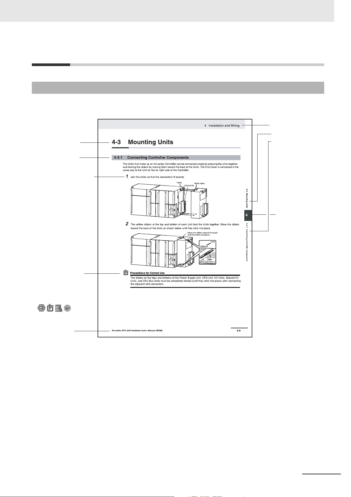
Level 1 heading
Level 2 heading
Level 3 heading
Level 2 heading
A step in a procedure
Manual name
Special information
Level 3 heading
Page tab
Gives the current
headings.
Indicates a procedure.
Icons indicate
precautions, additional
information, or reference
information.
Gives the number
of the main section.
Page Structure and Icons
The following page structure and icons are used in this manual.
Manual Structure
Note This illustration is provided only as a sample. It may not literally appear in this manual.
NX-series Data Reference Manual (W525)
5
Page 8

Manual Structure
Precautions for Safe Use
Precautions for Correct Use
Additional Information
Version Information
Special Information
Special information in this manual is classified as follows:
Precautions on what to do and what not to do to ensure safe usage of the product.
Precautions on what to do and what not to do to ensure proper operation and performance.
Additional information to read as required.
This information is provided to increase understanding or make operation easier.
Information on differences in specifications and functionality for CPU Units, Industrial PCs,
Communications Coupler Units, and Communication Control Units with different unit versions
and for different versions of the Support Software is given.
Note References are provided to more detailed or related information.
6
NX-series Data Reference Manual (W525)
Page 9
Precaution on Terminology
• In this manual, “download” refers to transferring data from the Support Software to a physical device
and “upload” refers to transferring data from a physical device to the Support Software.
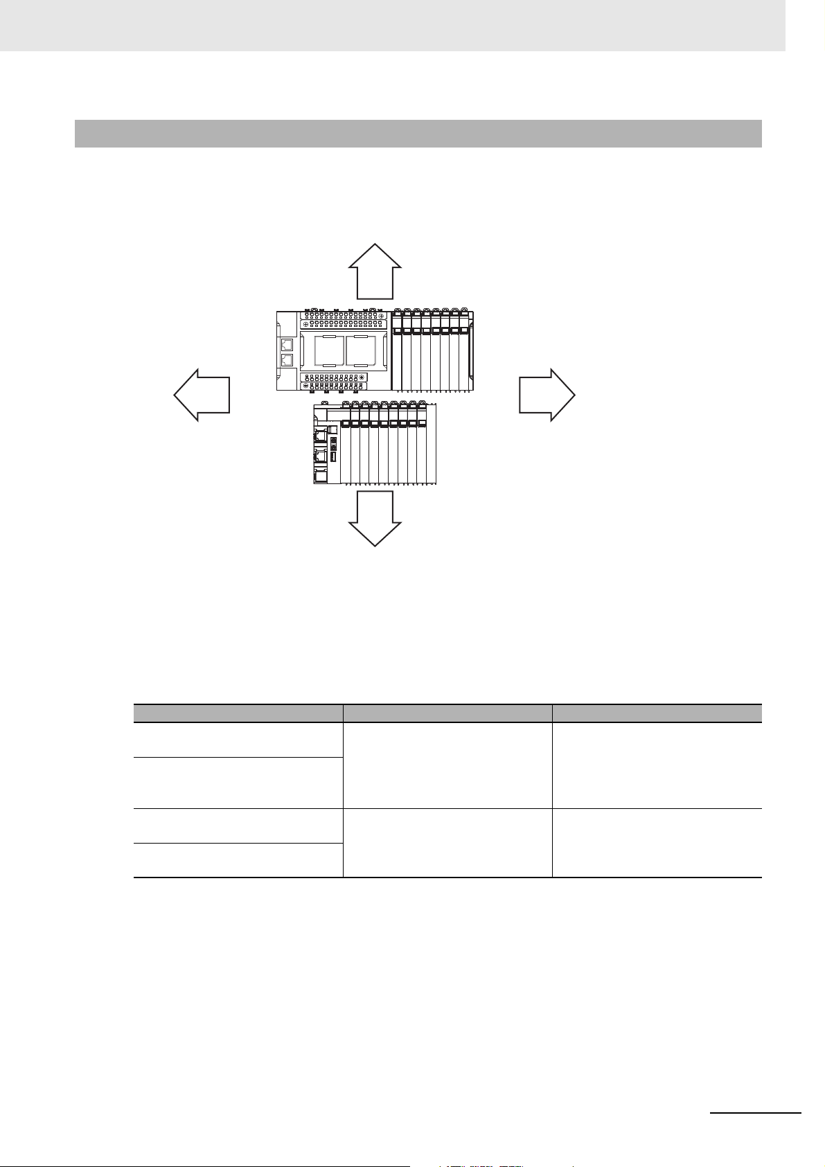
• In this manual, the directions in relation to the Units are given in the following figure, which shows
upright installation.
Manual Structure
Up
RightLeft
Down
• This user's manual refers to the NY-series IPC Machine Controller Industrial Panel PCs and Industrial Box PCs as simply Industrial PCs or as NY-series Industrial PCs.
• This user's manual may omit manual names and manual numbers in places that refer to the user's
manuals for CPU Units and Industrial PCs. The following table gives some examples. When necessary, refer to Related Manuals on page 14 to determine the appropriate manual based on the common text for the omitted contents.
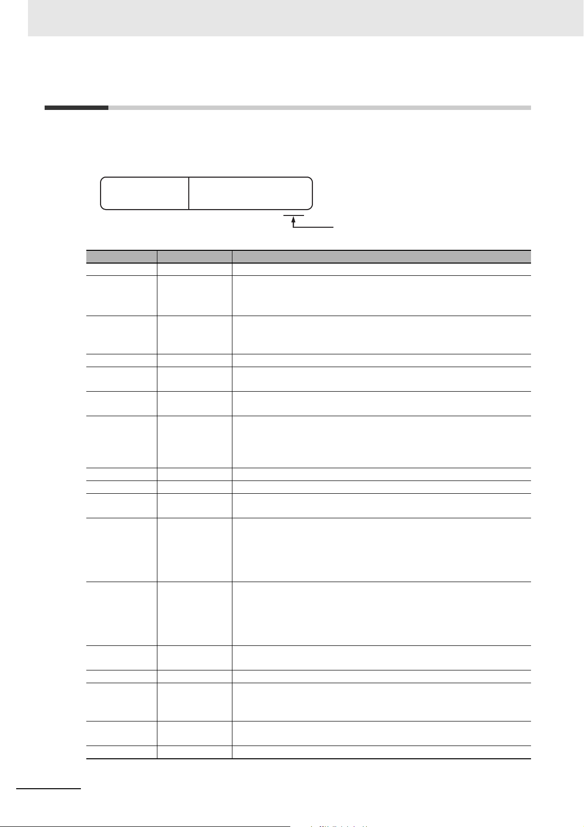
Examples:
Manual name Omitted contents Common text
NJ/NX-series CPU Unit Software
User's Manual
NY-series IPC Machine Controller
Industrial Panel PC / Industrial Box
PC Software User's Manual
NJ/NX-series Instructions Reference Manual
NY-series Instructions Reference
Manual
Software user's manual for the connected CPU Unit or Industrial PC
Instructions reference manual for
the connected CPU Unit or Industrial PC
Software User's Manual
Instructions Reference Manual
• This user's manual may omit manual names and manual numbers in places that refer to the user's
manuals for Communications Coupler Units. If you use a Communications Coupler Unit, refer to
Related Manuals on page 14 to identify the manual for your Unit.
• This user’s manual may omit manual names and manual numbers in places that refer to the user’s
manuals for Communication Control Units. If you use a Communication Control Unit, refer to Related
Manuals on page 14 to identify the manual for your Unit.
NX-series Data Reference Manual (W525)
7
Page 10

Terms and Conditions Agreement
Terms and Conditions Agreement
Warranty, Limitations of Liability
Warranties
z Exclusive Warranty
Omron’s exclusive warranty is that the Products will be free from defects in materials and workmanship for a period of twelve months from the date of sale by Omron (or such other period expressed in
writing by Omron). Omron disclaims all other warranties, express or implied.
z Limitations
OMRON MAKES NO WARRANTY OR REPRESENTATION, EXPRESS OR IMPLIED, ABOUT
NON-INFRINGEMENT, MERCHANTABILITY OR FITNESS FOR A PARTICULAR PURPOSE OF
THE PRODUCTS. BUYER ACKNOWLEDGES THAT IT ALONE HAS DETERMINED THAT THE
PRODUCTS WILL SUITABLY MEET THE REQUIREMENTS OF THEIR INTENDED USE.
Omron further disclaims all warranties and responsibility of any type for claims or expenses based
on infringement by the Products or otherwise of any intellectual property right.
z Buyer Remedy
Omron’s sole obligation hereunder shall be, at Omron’s election, to (i) replace (in the form originally
shipped with Buyer responsible for labor charges for removal or replacement thereof) the non-complying Product, (ii) repair the non-complying Product, or (iii) repay or credit Buyer an amount equal
to the purchase price of the non-complying Product; provided that in no event shall Omron be
responsible for warranty, repair, indemnity or any other claims or expenses regarding the Products
unless Omron’s analysis confirms that the Products were properly handled, stored, installed and
maintained and not subject to contamination, abuse, misuse or inappropriate modification. Return of
any Products by Buyer must be approved in writing by Omron before shipment. Omron Companies
shall not be liable for the suitability or unsuitability or the results from the use of Products in combination with any electrical or electronic components, circuits, system assemblies or any other materials or substances or environments. Any advice, recommendations or information given orally or in
writing, are not to be construed as an amendment or addition to the above warranty.
See http://www.omron.com/global/ or contact your Omron representative for published information.
Limitation on Liability; Etc
OMRON COMPANIES SHALL NOT BE LIABLE FOR SPECIAL, INDIRECT, INCIDENTAL, OR CONSEQUENTIAL DAMAGES, LOSS OF PROFITS OR PRODUCTION OR COMMERCIAL LOSS IN ANY
WAY CONNECTED WITH THE PRODUCTS, WHETHER SUCH CLAIM IS BASED IN CONTRACT,
WARRANTY, NEGLIGENCE OR STRICT LIABILITY.
Further, in no event shall liability of Omron Companies exceed the individual price of the Product on
which liability is asserted.
8
NX-series Data Reference Manual (W525)
Page 11

Application Considerations
Suitability of Use
Omron Companies shall not be responsible for conformity with any standards, codes or regulations
which apply to the combination of the Product in the Buyer’s application or use of the Product. At
Buyer’s request, Omron will provide applicable third party certification documents identifying ratings
and limitations of use which apply to the Product. This information by itself is not sufficient for a complete determination of the suitability of the Product in combination with the end product, machine, system, or other application or use. Buyer shall be solely responsible for determining appropriateness of
the particular Product with respect to Buyer’s application, product or system. Buyer shall take application responsibility in all cases.
NEVER USE THE PRODUCT FOR AN APPLICATION INVOLVING SERIOUS RISK TO LIFE OR
PROPERTY OR IN LARGE QUANTITIES WITHOUT ENSURING THAT THE SYSTEM AS A WHOLE
HAS BEEN DESIGNED TO ADDRESS THE RISKS, AND THAT THE OMRON PRODUCT(S) IS
PROPERLY RATED AND INSTALLED FOR THE INTENDED USE WITHIN THE OVERALL EQUIPMENT OR SYSTEM.
Terms and Conditions Agreement
Programmable Products
Omron Companies shall not be responsible for the user’s programming of a programmable Product, or
any consequence thereof.
Disclaimers
Performance Data
Data presented in Omron Company websites, catalogs and other materials is provided as a guide for
the user in determining suitability and does not constitute a warranty. It may represent the result of
Omron’s test conditions, and the user must correlate it to actual application requirements. Actual performance is subject to the Omron’s Warranty and Limitations of Liability.
Change in Specifications
Product specifications and accessories may be changed at any time based on improvements and other
reasons. It is our practice to change part numbers when published ratings or features are changed, or
when significant construction changes are made. However, some specifications of the Product may be
changed without any notice. When in doubt, special part numbers may be assigned to fix or establish
key specifications for your application. Please consult with your Omron’s representative at any time to
confirm actual specifications of purchased Product.
Errors and Omissions
Information presented by Omron Companies has been checked and is believed to be accurate; however, no responsibility is assumed for clerical, typographical or proofreading errors or omissions.
NX-series Data Reference Manual (W525)
9
Page 12

Safety Precautions
Safety Precautions
Refer to the user's manual for the Unit to be used for safety precautions.
10
NX-series Data Reference Manual (W525)
Page 13

Precautions for Safe Use
Refer to the user's manual for the Unit to be used for precautions for safe use.
Precautions for Safe Use
NX-series Data Reference Manual (W525)
11
Page 14

Precautions for Correct Use
Precautions for Correct Use
Refer to the user's manual for the Unit to be used for precautions for correct use.
12
NX-series Data Reference Manual (W525)
Page 15

Regulations and Standards
Refer to the user's manual for the Unit to be used for regulations and standards.
Regulations and Standards
NX-series Data Reference Manual (W525)
13
Page 16

Related Manuals
Related Manuals
The following table shows related manuals. Use these manuals for reference.
Manual name Cat. No. Model numbers Application Description
NX-series Data Reference Manual
NX-series Digital I/O
Units User’s Manual
NX-series Analog I/O
Units User’s Manual for
Analog Input Units and
Analog Output Units
NX-series Analog I/O
Units User’s Manual for
High-speed Analog
Input Units
NX-series Analog I/O
Units User’s Manual for
Temperature Input Units
and Heater Burnout
Detection Units
NX-series System Units
User’s Manual
NX-series Position Interface Units User’s Manual
NX-series Communications Interface Units
User’s Manual
NX-series
Load Cell Input Unit
User's Manual
NX-series
IO-Link Master Unit
User’s Manual
NX-series Temperature
Control Unit User’s Manual
*1
*2
W525 NX- Referencing lists of
the data that is
required to configure systems with
NX-series Units
W521 NX-ID
NX-IA
NX-OC
NX-OD
NX-MD
W522 NX-AD
NX-DA
W592 NX-HAD Learning how to
W566 NX-TS
NX-HB
W523 NX-PD1
NX-PF0
NX-PC0
NX-TBX01
W524 NX-EC0
NX-ECS
NX-PG0
W540 NX-CIF Learning how to
W565 NX-RS Learning how to
W567 NX-ILM Learning how to
H228 NX-TC Learning how to
Learning how to
use NX-series Digital I/O Units
Learning how to
use NX-series
Analog Input Units
and Analog Output Units
use NX-series
High-speed Analog
Input Units
Learning how to
use NX-series
Temperature Input
Units and Heater
Burnout Detection
Units
Learning how to
use NX-series
System Units
Learning how to
use NX-series
Position Interface
Units
use NX-series
Communications
Interface Units
use an NX-series
Load Cell Input
Unit
use an NX-series
IO-Link Master
Unit
use NX-series
Temperature Control Units
Lists of the power consumptions,
weights, and other NX Unit data that is
required to configure systems with
NX-series Units are provided.
The hardware, setup methods, and
functions of the NX-series Digital I/O
Units are described.
The hardware, setup methods, and
functions of the NX-series Analog Input
Units and Analog Output Units are
described.
The hardware, setup methods, and
functions of the NX-series High-speed
Analog Input Units are described.
The hardware, setup methods, and
functions of the NX-series Temperature
Input Units and Heater Burnout Detection Units are described.
The hardware and functions of the
NX-series System Units are described.
The hardware, setup methods, and
functions of the NX-series Incremental
Encoder Input Units, SSI Input Units,
and Pulse Output Unit are described.
The hardware, setup methods, and
functions of the NX-series Communications Interface Units are described.
The hardware, setup methods, and
functions of the NX-series Load Cell
Input Unit are described.
The names and functions of the parts,
installation, wiring and a list of NX
objects of the NX-series IO-Link Master
Unit are described.
The hardware, setup methods, and
functions of NX-series Temperature
Control Units are described.
14
NX-series Data Reference Manual (W525)
Page 17

Manual name Cat. No. Model numbers Application Description
NX-series RFID Units
User's Manual
NX-series Safety Control Unit User’s Manual
Sysmac Studio Version
1 Operation Manual
NX-IO Configurator
Operation Manual
NX-series EtherCAT®
Coupler Unit User’s
Manual
NX-series Ether-
TM
Net/IP
User’s Manual
NX-series CPU Unit
Hardware User’s Manual
NX-series NX102 CPU
Unit Hardware User’s
Manual
Coupler Unit
Z401 NX-V680C Learning how to
use NX-series
RFID Units
Z930 NX-SL
NX-SI
NX-SO
W504 SYSMAC-
SE2
W585 CXONE-AL
D-V4
W519 NX-ECC20 Learning how to
W536 NX-EIC202 Learning how to
W535 NX701- Learning the basic
W593 NX102- Learning the basic
Learning how to
use NX-series
Safety Control
Units
Learning about the
operating procedures and functions of the
Sysmac Studio
Learning about the
operating procedures and functions of the NX-IO
Configurator.
use an NX-series
EtherCAT Coupler
Unit and EtherCAT Slave Terminals
use an NX-series
EtherNet/IP Coupler Unit and EtherNet/IP Slave
Terminals
specifications of
the NX-series
NX701 CPU Units,
including introductory information,
designing, installation, and maintenance.
Mainly hardware
information is provided.
specifications of
the NX-series
NX102 CPU Units,
including introductory information,
designing, installation, and maintenance. Mainly
hardware information is provided.
The hardware, setup methods, and
functions of NX-series RFID Units are
described.
The hardware, setup methods, and
functions of the NX-series Safety Control Units are described.
Describes the operating procedures of
the Sysmac Studio.
Describes the operating procedures of
the NX-IO Configurator.
The following items are described: the
overall system and configuration methods of an EtherCAT Slave Terminal
(which consists of an NX-series EtherCAT Coupler Unit and NX Units), and
information on hardware, setup, and
functions to set up, control, and monitor
NX Units through EtherCAT.
The following items are described: the
overall system and configuration methods of an EtherNet/IP Slave Terminal
(which consists of an NX-series EtherNet/IP Coupler Unit and NX Units), and
information on hardware, setup, and
functions to set up, control, and monitor
NX Units.
An introduction to the entire NX701
CPU Unit system is provided along with
the following information on the CPU
Unit.
• Features and system configuration
• Overview
• Part names and functions
• General specifications
• Installation and wiring
• Maintenance and Inspection
An introduction to the entire NX102
CPU Unit system is provided along with
the following information on the CPU
Unit.
• Features and system configuration
• Overview
• Part names and functions
• General specifications
• Installation and wiring
• Maintenance and inspection
Related Manuals
NX-series Data Reference Manual (W525)
15
Page 18

Related Manuals
Manual name Cat. No. Model numbers Application Description
NX-series NX1P2 CPU
Unit Hardware User’s
Manual
NJ-series CPU Unit
Hardware User’s Manual
NJ/NX-series CPU Unit
Software User's Manual
NJ/NX-series Instructions Reference Manual
NY-series IPC Machine
Controller Industrial
Panel PC Hardware
User’s Manual
W578 NX1P2- Learning the basic
specifications of
the NX-series
NX1P2 CPU Units,
including introductory information,
designing, installation, and maintenance. Mainly
hardware information is provided.
W500 NJ501-
NJ301-
NJ101-
W501 NX701-
NJ501-
NJ301-
NJ101-
NX102-
NX1P2-
W502 NX701-
NJ501-
NJ301-
NJ101-
NX102-
NX1P2-
W557 NY532- Learning the basic
Learning the basic
specifications of
the NJ-series CPU
Units, including
introductory information, designing,
installation, and
maintenance.
Mainly hardware
information is provided.
Learning how to
program and set
up an
NJ/NX-series CPU
Unit.
Mainly software
information is provided.
Learning detailed
specifications on
the basic instructions of an
NJ/NX-series CPU
Unit.
specifications of
the NY-series
Industrial Panel
PCs, including
introductory information, designing,
installation, and
maintenance.
Mainly hardware
information is provided.
An introduction to the entire NX1P2
CPU Unit system is provided along with
the following information on the CPU
Unit.
• Features and system configuration
• Overview
• Part names and functions
• General specifications
• Installation and wiring
• Maintenance and Inspection
An introduction to the entire NJ-series
system is provided along with the following information on the CPU Unit.
• Features and system configuration
• Overview
• Part names and functions
• General specifications
• Installation and wiring
• Maintenance and Inspection
The following information is provided
on an NJ/NX-series CPU Unit.
• CPU Unit operation
• CPU Unit features
• Initial settings
• Programming based on IEC 61131-3
language specifications
The instructions in the instruction set
(IEC 61131-3 specifications) are
described.
An introduction to the entire NY-series
system is provided along with the following information on the Industrial
Panel PC.
• Features and system configuration
• Introduction
• Part names and functions
• General specifications
• Installation and wiring
• Maintenance and inspection
16
NX-series Data Reference Manual (W525)
Page 19

Related Manuals
Manual name Cat. No. Model numbers Application Description
NY-series IPC Machine
Controller Industrial Box
PC Hardware User’s
Manual
NY-series IPC Machine
Controller Industrial
Panel PC / Industrial
Box PC Software User’s
Manual
NY-series Instructions
Reference Manual
NX-series Safety Control Unit / Communication Control Unit User’s
Manual
*1. From revision 05 of this manual, information on the NX-series Temperature Input Units (NX-TS) that were includ-
ed in previous revisions was moved to the following manual: NX-series Analog I/O Units User's Manual for Temperature
Input Units and Heater Burnout Detection Units (Cat. No. W566). Accompanying that change, the name of this manual
was changed from the NX-series Analog I/O Units User's Manual (Cat. No. W522) to the NX-series Analog I/O Units Us-
er's Manual for Analog Input Units and Analog Output Units (Cat. No. W522).
*2. The NX-series Temperature Input Units (NX-TS) that were included in the NX-series Analog I/O Units User's Man-
ual (Cat No. W522) in revision 04 and earlier revisions were moved to this manual.
W556 NY512- Learning the basic
specifications of
the NY-series
Industrial Box PCs,
including introductory information,
designing, installation, and maintenance.
Mainly hardware
information is provided.
W558 NY532-
NY512-
W560 NY532-
NY512-
Z395 NX-SL5
NX-SI
NX-SO
NX-CSG
Learning how to
program and set
up the Controller
functions of an
NY-series Industrial PC.
Learning detailed
specifications on
the basic instructions of an
NY-series Industrial PC.
Learning how to
use the NX-series
Safety Control
Units and Communication Control
Units.
An introduction to the entire NY-series
system is provided along with the following information on the Industrial Box
PC.
• Features and system configuration
• Introduction
• Part names and functions
• General specifications
• Installation and wiring
• Maintenance and inspection
The following information is provided
on NY-series Machine Automation Control Software.
• Controller operation
• Controller features
• Controller settings
• Programming based on IEC 61131-3
language specifications
The instructions in the instruction set
(IEC 61131-3 specifications) are
described.
Describes the hardware, setup methods, and functions of the NX-series
Safety Control Units and Communication Control Units.
NX-series Data Reference Manual (W525)
17
Page 20
Revision History
Cat. No.
W525-E1-21
Revision code
Revision History
A manual revision code appears as a suffix to the catalog number on the front and back covers of the
manual.
Revision code Date Revised content
01 April 2013 Original production
02 June 2013 • Added models on time stamp refreshing.
03 September 2013 • Added new models and made changes accompanying the upgrade to
04 July 2014 Added new models in July 2014.
05 December 2014 Made changes accompanying the addition of the EtherNet/IP Coupler
06 April 2015 Added new models and made changes accompanying the upgrade to the
07 April 2016 • Made changes accompanying the addition of new models for Pulse Out-
08 April 2016 Added Heater Burnout Detection Units.
09 July 2016 Added IO-Link Master Unit.
10 July 2016 Made changes accompanying the unit version upgrade of the EtherCAT
11 October 2016 • Made changes accompanying the addition of NY-series IPC Machine
12 June 2017 • Made changes accompanying the upgrade of the NX-ECC203 unit ver-
13 October 2017 Made changes accompanying the upgrade of the NX-ILM400 unit version
14 January 2018 Added Temperature Control Units.
15 April 2018 • Made changes accompanying the upgrade of the Temperature Control
16 April 2018 Made changes accompanying the addition of the NX-series NX102 CPU
17 May 2018 Added High-speed Analog Input Units.
• Added Safety Control Units.
• Corrected mistakes.
the unit version in September 2013.
• Corrected mistakes.
Units.
unit version in April 2015.
put Unit of Position Interface Unit.
• Added Load Cell Input Unit.
• Corrected mistakes.
Coupler Unit NX-ECC203.
Controller Industrial Panel PCs and Industrial Box PCs.
• Made changes accompanying the addition of the NX-series NX1P2 CPU
Unit.
• Corrected mistakes.
sion to version 1.5.
• Made changes accompanying the upgrade of the NX-EIC202 unit version to version 1.2.
• Corrected mistakes.
to version 1.1.
Units version to version 1.1.
• Corrected mistakes.
Unit.
18
NX-series Data Reference Manual (W525)
Page 21

Revision History
Revision code Date Revised content
18 July 2018 • Made changes accompanying the addition of new models for the
NX-series NX102 CPU Unit.
• Made changes accompanying the addition of the NX-series Communica-
tion Control Unit.
• Made changes accompanying the addition of new models for the
NX-series Safety CPU Unit.
• Corrected mistakes.
19 October 2018 • Added RFID Units.
• Made changes accompanying the upgrade of the NX-ECC203 unit ver-
sion to version 1.6.
20 October 2019 • Made changes accompanying the upgrade of the NX-TC unit version to
version 1.2.
• Made changes accompanying the addition of new models for the
NX-series NX1P2 CPU Unit.
21 April 2020 Made changes accompanying the upgrade of the NX-TC unit version to
version 1.3.
NX-series Data Reference Manual (W525)
19
Page 22

Revision History
20
NX-series Data Reference Manual (W525)
Page 23

1
A
1
A
9
Data List
Appendices
Sections in this Manual
Sections in this Manual
NX-series Data Reference Manual (W525)
21
Page 24

Sections in this Manual
22
NX-series Data Reference Manual (W525)
Page 25

Data List
This section provides the data lists for CPU Units, Communications Coupler Units,
Communication Control Units, and NX Units.
1-1 How to Read the Data List . . . . . . . . . . . . . . . . . . . . . . . . . . . . . . . . . . . . . . . 1-3
1-2 CPU Units . . . . . . . . . . . . . . . . . . . . . . . . . . . . . . . . . . . . . . . . . . . . . . . . . . . . 1-6
1-3 Communications Coupler Units . . . . . . . . . . . . . . . . . . . . . . . . . . . . . . . . . . 1-8
1-4 Communication Control Units . . . . . . . . . . . . . . . . . . . . . . . . . . . . . . . . . . 1-10
1
1-2-1 NX1P2 CPU Units . . . . . . . . . . . . . . . . . . . . . . . . . . . . . . . . . . . . . . . . . . . . . . . 1-6
1-2-2 NX102 CPU Units . . . . . . . . . . . . . . . . . . . . . . . . . . . . . . . . . . . . . . . . . . . . . . . 1-7
1-3-1 EtherCAT Coupler Unit . . . . . . . . . . . . . . . . . . . . . . . . . . . . . . . . . . . . . . . . . . . 1-8
1-3-2 EtherNet/IP Coupler Unit . . . . . . . . . . . . . . . . . . . . . . . . . . . . . . . . . . . . . . . . . 1-9
1-3-3 End Cover . . . . . . . . . . . . . . . . . . . . . . . . . . . . . . . . . . . . . . . . . . . . . . . . . . . . . 1-9
1-5 Digital I/O Units . . . . . . . . . . . . . . . . . . . . . . . . . . . . . . . . . . . . . . . . . . . . . . 1-11
1-5-1 Digital Input Units . . . . . . . . . . . . . . . . . . . . . . . . . . . . . . . . . . . . . . . . . . . . . . .1-11
1-5-2 Digital Output Units . . . . . . . . . . . . . . . . . . . . . . . . . . . . . . . . . . . . . . . . . . . . . 1-17
1-5-3 Digital Mixed I/O Units . . . . . . . . . . . . . . . . . . . . . . . . . . . . . . . . . . . . . . . . . . 1-24
1-6 Analog I/O Units . . . . . . . . . . . . . . . . . . . . . . . . . . . . . . . . . . . . . . . . . . . . . . 1-27
1-6-1 Analog Input Units . . . . . . . . . . . . . . . . . . . . . . . . . . . . . . . . . . . . . . . . . . . . . 1-27
1-6-2 High-speed Analog Input Units . . . . . . . . . . . . . . . . . . . . . . . . . . . . . . . . . . . . 1-29
1-6-3 Analog Output Units . . . . . . . . . . . . . . . . . . . . . . . . . . . . . . . . . . . . . . . . . . . . 1-30
1-6-4 Temperature Input Units . . . . . . . . . . . . . . . . . . . . . . . . . . . . . . . . . . . . . . . . . 1-31
1-6-5 Heater Burnout Detection Units . . . . . . . . . . . . . . . . . . . . . . . . . . . . . . . . . . . 1-33
1-7 Position Interface Units . . . . . . . . . . . . . . . . . . . . . . . . . . . . . . . . . . . . . . . . 1-34
1-7-1 Incremental Encoder Input Units . . . . . . . . . . . . . . . . . . . . . . . . . . . . . . . . . . 1-34
1-7-2 SSI Input Units . . . . . . . . . . . . . . . . . . . . . . . . . . . . . . . . . . . . . . . . . . . . . . . . 1-35
1-7-3 Pulse Output Units . . . . . . . . . . . . . . . . . . . . . . . . . . . . . . . . . . . . . . . . . . . . . 1-36
1-8 Communications Interface Units . . . . . . . . . . . . . . . . . . . . . . . . . . . . . . . . 1-38
1-9 Load Cell Input Unit . . . . . . . . . . . . . . . . . . . . . . . . . . . . . . . . . . . . . . . . . . . 1-39
1-10 IO-Link Master Unit . . . . . . . . . . . . . . . . . . . . . . . . . . . . . . . . . . . . . . . . . . . 1-40
1-11 Temperature Control Units . . . . . . . . . . . . . . . . . . . . . . . . . . . . . . . . . . . . . 1-41
1-12 RFID Units . . . . . . . . . . . . . . . . . . . . . . . . . . . . . . . . . . . . . . . . . . . . . . . . . . . 1-43
NX-series Data Reference Manual (W525)
1 - 1
Page 26

1 Data List
1-13 System Units . . . . . . . . . . . . . . . . . . . . . . . . . . . . . . . . . . . . . . . . . . . . . . . . . 1-44
1-13-1 Additional NX Unit Power Supply Unit . . . . . . . . . . . . . . . . . . . . . . . . . . . . . . .1-44
1-13-2 Additional I/O Power Supply Unit . . . . . . . . . . . . . . . . . . . . . . . . . . . . . . . . . . .1-44
1-13-3 I/O Power Supply Connection Unit . . . . . . . . . . . . . . . . . . . . . . . . . . . . . . . . . .1-45
1-13-4 Shield Connection Unit . . . . . . . . . . . . . . . . . . . . . . . . . . . . . . . . . . . . . . . . . . .1-46
1-14 Safety Control Units . . . . . . . . . . . . . . . . . . . . . . . . . . . . . . . . . . . . . . . . . . . 1-47
1-14-1 Safety CPU Unit . . . . . . . . . . . . . . . . . . . . . . . . . . . . . . . . . . . . . . . . . . . . . . . . 1-47
1-14-2 Safety Input Units . . . . . . . . . . . . . . . . . . . . . . . . . . . . . . . . . . . . . . . . . . . . . . .1-48
1-14-3 Safety Output Units . . . . . . . . . . . . . . . . . . . . . . . . . . . . . . . . . . . . . . . . . . . . . 1-49
1 - 2
NX-series Data Reference Manual (W525)
Page 27

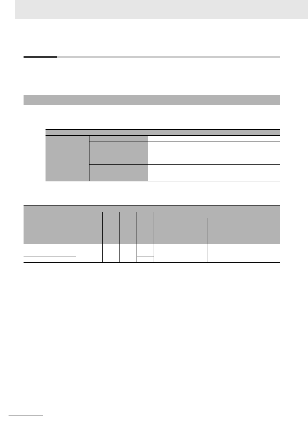
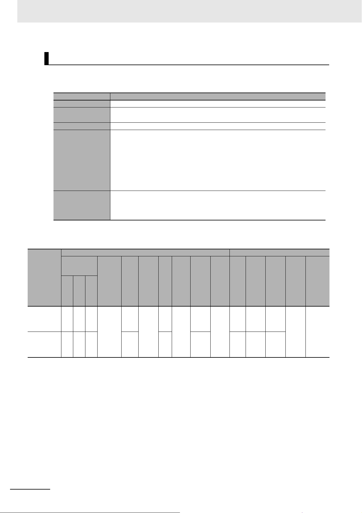
1-1 How to Read the Data List
This data list is described with the following format.
Example: For Digital Input Units
Unit configuration data Summary specifications
Model
NX Unit power con-
sumption [W]
Cou-
CPU
Con-
pler
trol
Current
con-
sump-
tion from
I/O
power
supply
[mA]
I/O
Input
powe
cur-
r sup-
rent
[mA]
meth
ply
od
Wei
ght
[g]
Width
[mm]
[byte]
I/O
data
size
Num-
ber of
I/O
entry
map-
pings
Num
ber
of
poin
ts
Intern
al I/O
com
mon
1 Data List
Rated
input
volt-
age
I/O
refres
hing
meth
od
1-1 How to Read the Data List
1
ON/OFF
respons
e time
The items for this format are explained below.
Unit Configuration Data
The Unit configuration data is the data required to create the CPU Rack configuration of the NX-series
CPU Unit or NX-series Communication Control Unit, or to create the Unit configuration of Slave Terminal. In this manual, Unit configuration is described only for NX Units, CPU Units connectable to NX
Units, Communications Coupler Units, and Communication Control Units. The data of the built-in I/O of
NX1P2 CPU Units and Option Boards are not shown.
Create the Unit configuration so that the total value of the data for which the maximum value is defined
does not exceed the maximum value of the CPU Rack or Slave Terminal.
Refer to the user’s manual for the connected CPU Unit, Communications Coupler Unit, or Communication Control Unit on the maximum value for each data.
Yes: Data to be referred to create the target configuration
No: Data not to be referred to create the target configuration
Configuration to create
CPU
Item Description
Unit power consumption
The power consumption of the CPU Unit or the Communication Control Unit from the Unit power supply.
CPU
Rack for
CPU Unit
Yes No Yes
Slave
Ter minal
Rack for
Communication
Control
Unit
NX-series Data Reference Manual (W525)
1 - 3
Page 28

1 Data List
NX Unit
power con-
sumption
Current consumption
from I/O power supply
Input current
I/O power supply
method
Item Description
The power consumption of the Unit connected to the CPU Unit
from the NX Unit power supply. The item name is abbreviated
as “CPU”.
If any value or this item is not provided, the Unit cannot be
connected to any CPU Unit.
The power consumption of the Unit connected to the Communications Coupler Unit from the NX Unit power supply. The
item name is abbreviated as “Coupler”.
If any value or this item is not provided, the Unit cannot be
connected to any Communications Coupler Unit.
The power consumption of the Unit connected to the Communication Control Unit from the NX Unit power supply. The item
name is abbreviated as “Control”.
If any value or this item is not provided, the Unit cannot be
connected to any Communication Control Unit.
The current consumption from I/O power supply of the Unit.
*3
The load current of any external connection load, the input
current of the Input Units, and the current consumption of any
connected external devices are not included.
The input current of the Unit at the rated voltage.
Only the DC Input Units and AC Input Units have this item.
The method for supplying I/O power supply for the Unit.
The supply method depends on each Unit.
The power is supplied from the NX bus or the external source.
*1*2
CPU
Coupler
Control
Configuration to create
CPU
Rack for
CPU Unit
Yes No N o
No Yes No
No No Yes
Yes
Yes
Yes
Slave
Term inal
Rack for
Commu-
nication
Control
CPU
Unit
NX bus: Supply from the NX bus
External: Supply from external source
The CPU Unit, Communications Coupler Unit, Communication
Control Unit, and the Additional I/O Power Supply Unit do not
have this item.
Weight
Width The width of the Unit. The unit is "mm". Yes
I/O data size
Number of I/O entry
mappings
Number of cyclic communications connec-
tions
*4
*7
The weight of the Unit. Yes
The I/O data size of default value that the Unit consumes. The
unit is byte.
However, the unit is bit for some Digital I/O Units. In this case,
the unit is given in the table.
It is described according to the input/output sequence.
The number of I/O entry mappings of default value that the
Unit consumes.
It is described according to the input/output sequence.
The maximum number of connections that can be set by
Class 1 messages.
Yes
No
No Yes No
*5
No
*6
Yes
No
*6
*1. CPU Units and Communication Control Units do not have this item. This item is defined as the Unit power con-
sumption from the Unit power supply.
*2. The Communications Coupler Units do not distinguish among CPU, Coupler and Control because they cannot
be mounted to the CPU Unit or Communication Control Unit.
*3. CPU Units do not have this item.
*4. CPU Units and Communication Control Units do not have this item.
*5. Communication Control Units provide a sufficient margin of capacity for the data size required to allocate I/O
data to NX Units which can be connected. For this reason, it is not necessary to consider the I/O data size of
the connected NX Units.
*6. There is no restriction for CPU Units and Communication Control Units.
1 - 4
NX-series Data Reference Manual (W525)
Page 29

1 Data List
*7. This item is only for EtherNet/IP Coupler Units.
Summary Specifications
The summary specifications of the Units to configure the CPU Rack or Slave Terminal.
Use this as a guide to select the Unit model when you consider the Unit configuration.
The items in the Summary Specifications depend on the Unit type. The meaning of each item is
explained for each Unit type.
1-1 How to Read the Data List
1
NX-series Data Reference Manual (W525)
1 - 5
Page 30
1 Data List
1-2 CPU Units
This section describes the data for CPU Units.
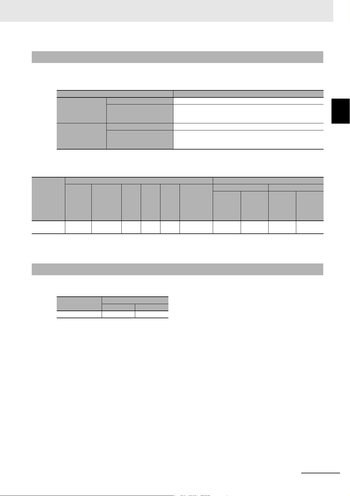
1-2-1 NX1P2 CPU Units
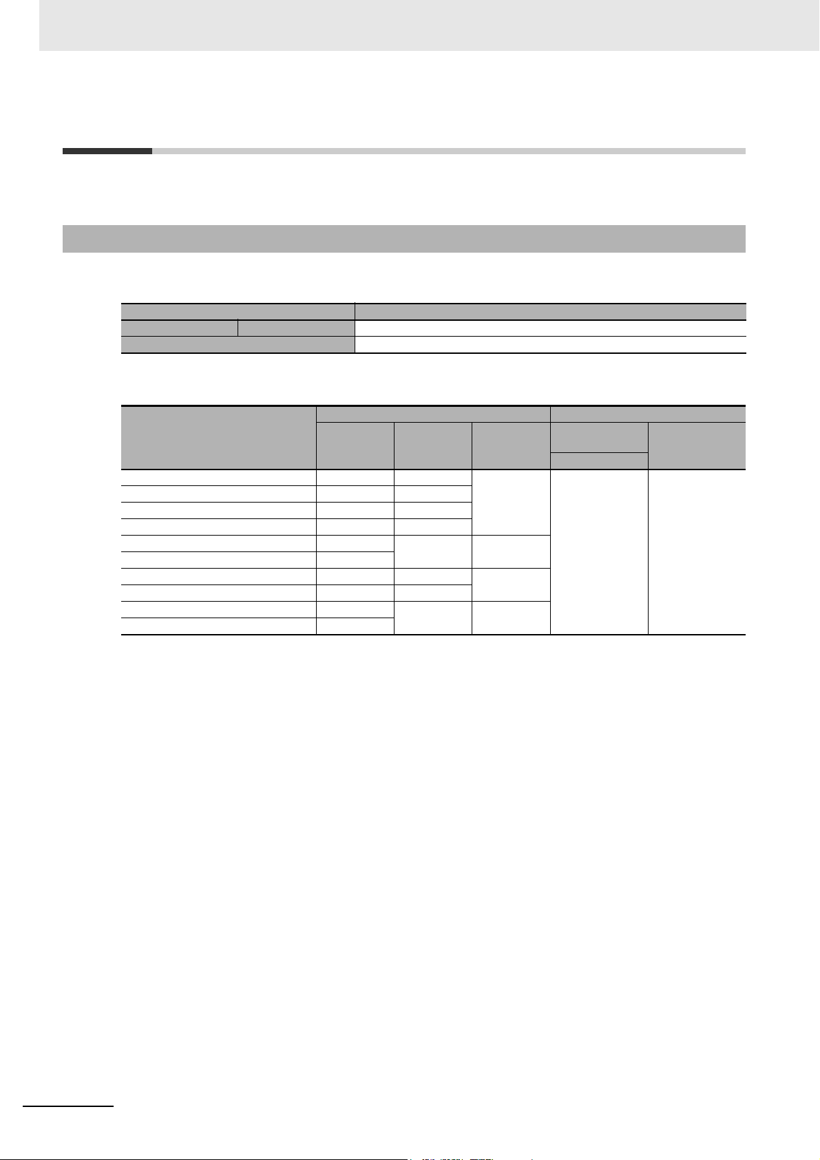
z Items in the Summary Specifications
Item Description
Unit power supply Rated voltage The rated voltage of the Unit power supply that is supplied to the Unit.
NX Unit power supply capacity The amount of power that the Unit can supply to the NX Units.
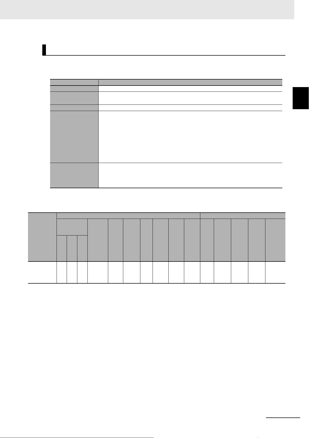
z Data List
Model
NX1P2-1040DT
NX1P2-1040DT1
NX1P2-1140DT
NX1P2-1140DT1
NX1P2-9024DT
NX1P2-9024DT1
NX1P2-9B40DT
NX1P2-9B40DT1
NX1P2-9B24DT
NX1P2-9B24DT1
*1. The power consumption of an SD Memory Card and Option Boards are included. The power consumption of
NX Units from the NX Unit power supply is not included.
*2. The weight of the End Cover is included.
*3. The NX Unit power supply capacity is not restricted by the ambient operating temperature.
Unit configuration data Summary specifications
Unit power
consump-
tion [W]
7.05 650 154 24 VDC 10 W max.
6.85 660
7.05 650
6.85 660
6.70 590 130
6.40
7.05 650 154
6.85 660
6.70 590 130
6.40
*1
Weight [g]
Width
*2
[mm]
*2
Unit power sup-
ply
Rated voltage
NX Unit power
supply capac-
ity
*3
1 - 6
NX-series Data Reference Manual (W525)
Page 31

1 Data List
1-2-2 NX102 CPU Units
z Items in the Summary Specifications
Item Description
Unit power supply Rated voltage The rated voltage of the Unit power supply that is supplied to the Unit.
NX Unit power supply capacity The amount of power that the Unit can supply to the NX Units.
z Data List
Model
NX102-1200 5.80 390 72 24 VDC 10 W max.
NX102-1100
NX102-1000
NX102-9000
NX102-1220
NX102-1120
NX102-1020
NX102-9020
*1. The power consumption of an SD Memory Card is included. The power consumption of NX Units from the NX
Unit power supply is not included.
*2. The weight of the End Cover is included.
*3. The NX Unit power supply capacity is not restricted by the ambient operating temperature.
Unit configuration data Summary specifications
Unit power
consumption
*1
[W]
Weight [g]
*2
Width [mm]
Unit power sup-
*2
Rated voltage
ply
NX Unit power
supply capac-
*3
ity
1-2 CPU Units
1
1-2-2 NX102 CPU Units
NX-series Data Reference Manual (W525)
1 - 7
Page 32
1 Data List
1-3 Communications Coupler Units
This section describes the data for Communications Coupler Units. This section also gives the data for
the End Cover that is an Accessory for the Communications Coupler Unit.
1-3-1 EtherCAT Coupler Unit
z Items in the Summary Specifications
Item Description
Unit power supply Rated voltage The rated voltage of the Unit power supply that is supplied to the Unit.
NX Unit power supply
capacity
I/O power supply Rated voltage The rated voltage of the I/O power supply that is supplied to the Unit.
Maximum current of I/O
power supply
The amount of power that the Unit can supply to the NX Units. The
power consumption of the Unit from the NX Unit power supply is not
included.
The maximum value of the current supplied from the I/O power supply
that the Unit can supply to the NX Units through the NX bus connectors.
z Data List
Unit configuration data Summary specifications
NX Unit
Model
NX-ECC201
NX-ECC202
NX-ECC203
*1. The NX Unit power supply capacity and the maximum current of I/O power supply are sometimes restricted by conditions such as the
temperature or installation orientation. For details, refer to A-1 NX Unit Power Supply and I/O Power Supply Capacity on page A-2.
power
con-
sump-
tion [W]
1.45
1.25 18/0
Current
consump-
tion from
I/O power
supply
[mA]
10 170 46
Weigh
t [g]
Width
[mm]
I/O
data
size
[byte]
34/0
Number of
I/O entry
mappings
2/0 24 VDC 10 W max.
Unit power supply I/O power supply
Rated
voltage
NX Unit
power
supply
capacity
*1
Rated
voltage
5 to 24
VDC
Maximum
current of
I/O power
supply
4 A
10 A
*1
1 - 8
NX-series Data Reference Manual (W525)
Page 33
1 Data List
1-3-2 EtherNet/IP Coupler Unit
z Items in the Summary Specifications
Item Description
Unit power supply Rated voltage The rated voltage of the Unit power supply that is supplied to the Unit.
NX Unit power supply
capacity
I/O power supply Rated voltage The rated voltage of the I/O power supply that is supplied to the Unit.
Maximum current of I/O
power supply
z Data List
Unit configuration data Summary specifications
NX Unit
Model
NX-EIC202
*1. The NX Unit power supply capacity and the maximum current of I/O power supply are sometimes restricted by conditions such as the
temperature or installation orientation. For details, refer to A-1 NX Unit Power Supply and I/O Power Supply Capacity on page A-2.
power
con-
sump-
tion [W]
1.60 10 150 46
Current
consump-
tion from
I/O power
supply
[mA]
Weigh
t [g]
Width
[mm]
The amount of power that the Unit can supply to the NX Units. The
power consumption of the Unit from the NX Unit power supply is not
included.
The maximum value of the current supplied from the I/O power supply
that the Unit can supply to the NX Units through the NX bus connectors.
Unit power supply I/O power supply
NX Unit
Rated
voltage
power
supply
capacity
*1
Rated
voltage
5 to 24
VDC
I/O
data
size
[byte]
1 to
504
Number of
cyclic com-
munica-
tions
connections
8 24 VDC 10 W max.
Maximum
current of
I/O power
supply
10 A
1-3 Communications Coupler
Units
1
1-3-2 EtherNet/IP Coupler Unit
*1
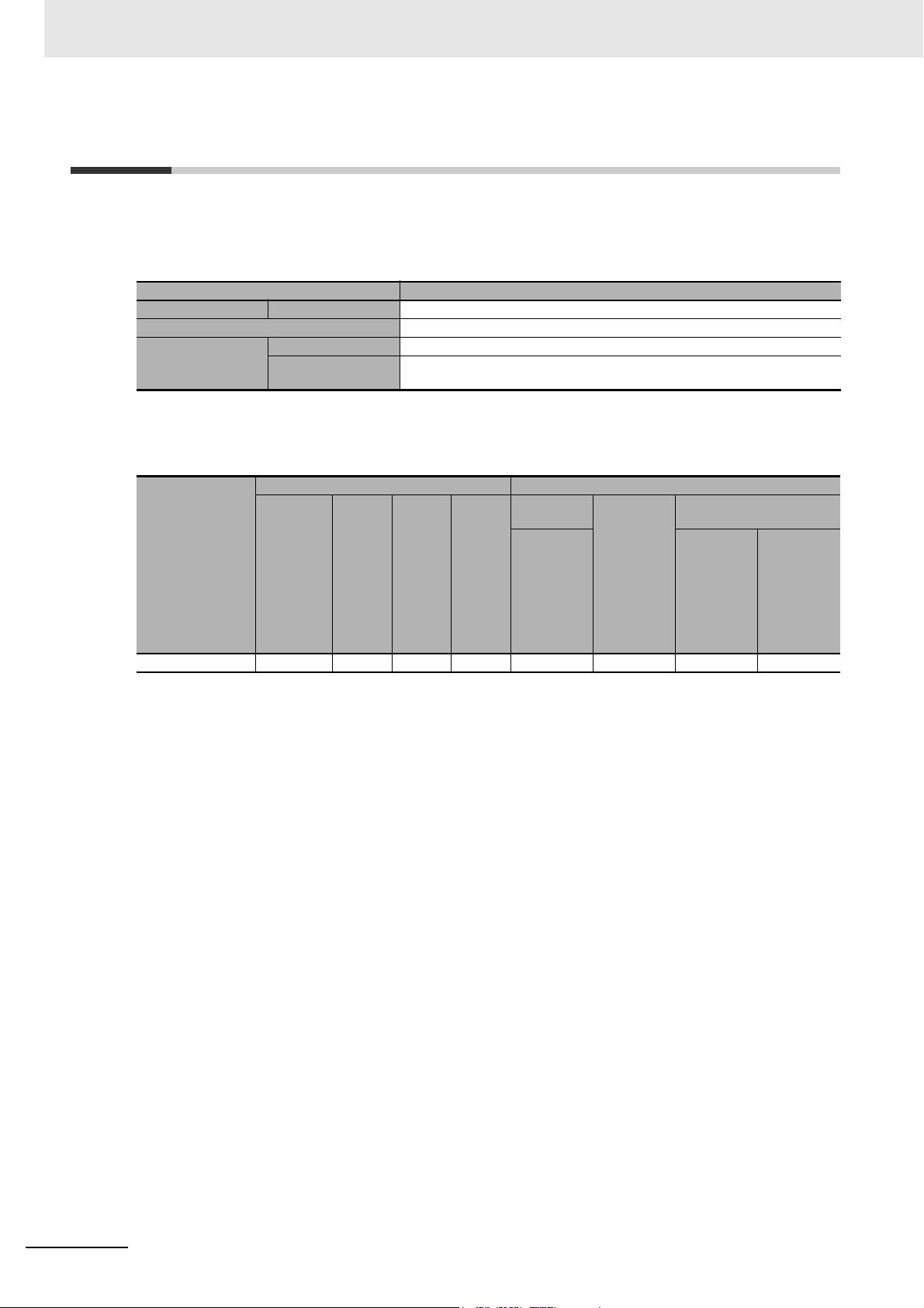
1-3-3 End Cover
z Data List
Model
NX-END01
Unit configuration data
Weight [g] Width [mm]
35 12
NX-series Data Reference Manual (W525)
1 - 9
Page 34
1 Data List
1-4 Communication Control Units
This section describes the data for Communication Control Units.
z Items in the Summary Specifications
Item Description
Unit power supply Rated voltage The rated voltage of the Unit power supply that is supplied to the Unit.
NX Unit power supply capacity The amount of power that the Unit can supply to the NX Units.
Rated voltage The rated voltage of the I/O power supply that is supplied to the Unit.
I/O power supply
z Data List
Model
NX-CSG320 5.95 10 390 72 24 VDC 10 W max. 5 to 24 VDC 4 A
*1. The power consumption of NX Units from the NX Unit power supply is not included.
*2. The weight of the End Cover is included.
*3. The NX Unit power supply capacity and the maximum current of I/O power supply are not restricted by the
ambient operating temperature.
Maximum current of
I/O power supply
Unit configuration data Summary specifications
Current
con-
*1
sump-
tion
from
I/O
power
supply
[mA]
Unit power
consump-
tion [W]
The maximum value of the current supplied from the I/O power supply that the
Unit can supply to the NX Units through the NX bus connectors.
Unit power
supply
NX Unit
Weight
*2
[g]
Width
[mm]
*2
Rated volt-
age
power
supply
capacity
*3
I/O power supply
Rated
voltage
Maximum
current of
I/O power
*3
supply
1 - 10
NX-series Data Reference Manual (W525)
Page 35

1-5 Digital I/O Units
This section describes the data for Digital I/O Units.
1 Data List
1-5 Digital I/O Units
1-5-1 Digital Input Units
DC Input Units (Screwless Clamping Terminal Block, 12 mm Width)
z Items in the Summary Specifications
Item Description
Number of points The number of input points provided by the Unit.
Internal I/O common This is the polarity that the Unit uses to connect to input devices.
There are models with NPN and PNP connections.
Rated input voltage The rated input voltage of the Unit.
I/O refreshing method The I/O refreshing methods that are used by the Unit.
Free-Run refreshing, synchronous I/O refreshing and input refreshing with input changed time are
available.
In the following table, the following abbreviations are used.
:
Free-Run refreshing
Free
Sync
: Switching
Changed time: Input refreshing with input changed time
ON/OFF response
time
The delay time for which the status change of the input terminals reaches the internal circuit of the
Unit.
The input filter time is not included.
It is described according to the ON/OFF sequence.
synchronous I/O refreshing
and
Free-Run refreshing
1
1-5-1 Digital Input Units
NX-series Data Reference Manual (W525)
1 - 11
Page 36
1 Data List
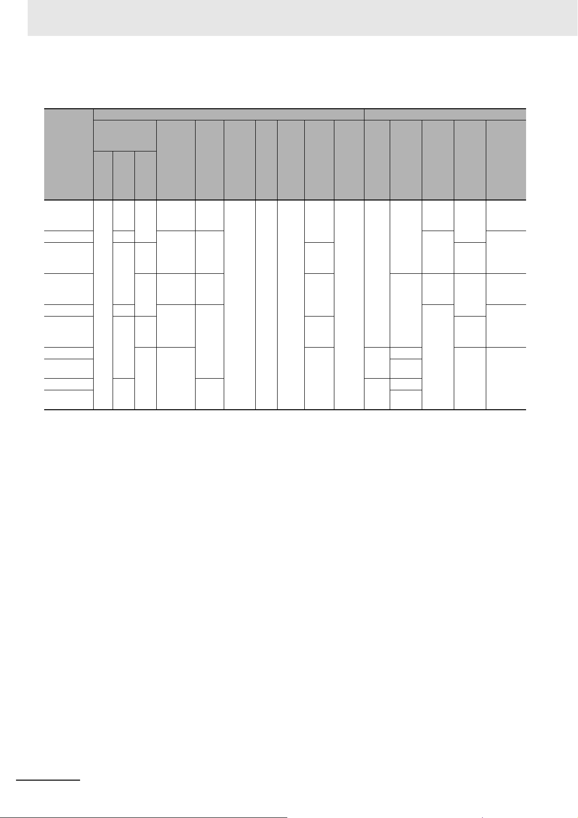
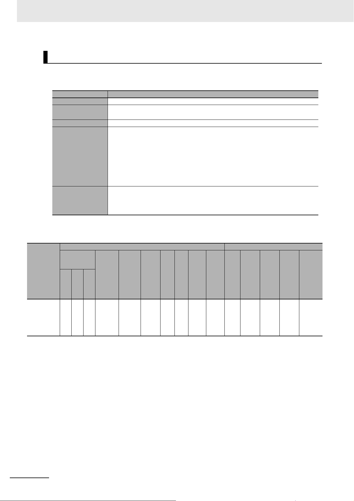
z Data List
NX Unit power
consumption
Model
CPU
NX-ID3317
NX-ID3343
NX-ID3344
NX-ID3417
NX-ID3443
NX-ID3444
NX-ID4342
NX-ID4442
NX-ID5342
NX-ID5442
0.90 0.50 0.90
Unit configuration data Summary specifications
Current
I/O
power
sup-
ply
metho
d
NX bus
Wei
Widt
ght
h
[g]
[mm]
[byte]
65 12 4/0
bits
bits
2/0 8
Co
ntr
ol
con-
sump-
tion
from I/O
power
supply
[mA]
No consumption
No consumption
No consumption
[W]
Cou-
pler
0.55 30 3.5 24
0.50 --- 34/0 Chang
0.90
0.55 30 3.5 24
0.50 --- 34/0 Chang
0.90
0.55 2.5 16
Input
current
[mA]
6
64/0
I/O
data
size
Num-
ber of
I/O
entry
map-
pings
1/0 4
Num
Inter-
ber
nal I/O
of
com-
poin
mon
ts
NPN 12 to
point
s
PNP 12 to
NPN Sync
point
PNP
s
NPN
point
PNP
s
Rated
input
volt-
age
24
VDC
VDC
24
VDC
VDC
I/O
refres
hing
metho
d
Sync
ed
time
Sync
ed
time
ON/OFF
respons
e time
20/400
μs
max.
100/
100 ns
max.
20/400
max.
μs
100/
100 ns
max.
20/400
max.
μs
1 - 12
NX-series Data Reference Manual (W525)
Page 37

DC Input Units (M3 Screw Terminal Block, 30 mm Width)
z Items in the Summary Specifications
Item Description
Number of points The number of input points provided by the Unit.
Internal I/O common This is the polarity that the Unit uses to connect to input devices.
There are models with NPN and PNP connections.
Rated input voltage The rated input voltage of the Unit.
I/O refreshing method The I/O refreshing methods that are used by the Unit.
Free-Run refreshing, synchronous I/O refreshing and input refreshing with input changed time are
available.
In the following table, the following abbreviations are used.
:
Free-Run refreshing
Free
ON/OFF response
time
: Switching
Sync
Changed time: Input refreshing with input changed time
The delay time for which the status change of the input terminals reaches the internal circuit of the
Unit.
The input filter time is not included.
It is described according to the ON/OFF sequence.
synchronous I/O refreshing
and
Free-Run refreshing
1 Data List
1-5 Digital I/O Units
1
1-5-1 Digital Input Units
Model
NX-ID5142-1
z Data List
NX Unit power
consumption
[W]
Cou-
CPU
pler
0.85 0.55 0.85
Con-
trol
Unit configuration data Summary specifications
Current
con-
sump-
tion
from I/O
power
supply
[mA]
No consumption
Input
current
[mA]
7
I/O
power
sup-
ply
meth
od
External
Widt
Wei
h
ght
[mm
[g]
]
[byte]
125 30 2/0 1/0
I/O
data
size
Num-
ber of
I/O
entry
map-
pings
Num
ber
of
poin
ts
16
point
s
Inter-
nal I/O
com-
mon
For
both
NPN/P
NP
Rated
input
volt-
age
24
VDC
I/O
refres
hing
metho
d
Sync
ON/OFF
respons
e time
20/400
μ
s max.
NX-series Data Reference Manual (W525)
1 - 13
Page 38
1 Data List
DC Input Units (MIL Connector, 30 mm Width)
z Items in the Summary Specifications
Number of points The number of input points provided by the Unit.
Internal I/O common This is the polarity that the Unit uses to connect to input devices.
Rated input voltage The rated input voltage of the Unit.
I/O refreshing method The I/O refreshing methods that are used by the Unit.
ON/OFF response
time
Item Description
There are models with NPN and PNP connections.
Free-Run refreshing, synchronous I/O refreshing and input refreshing with input changed time are
available.
In the following table, the following abbreviations are used.
Free: Free-Run refreshing
Sync: Switching synchronous I/O refreshing and Free-Run refreshing
Changed time: Input refreshing with input changed time
The delay time for which the status change of the input terminals reaches the internal circuit of the
Unit.
The input filter time is not included.
It is described according to the ON/OFF sequence.
Model
NX-ID5142-5
NX-ID6142-5
z Data List
Unit configuration data Summary specifications
NX Unit power
consumption
[W]
Cou
CPU
pler
0.85 0.55 0.85
0.90 0.60 0.90 4.1 90 4/0
Con
trol
Current
con-
sump-
tion
from I/O
power
supply
[mA]
No consumption
Input
current
[mA]
7
I/O
power
sup-
ply
metho
d
External
Wei
Width
ght
[mm]
[g]
85 30 2/0 1/0
I/O
data
size
[byte]
Num-
ber of
I/O
entry
map-
pings
Num
ber
of
poin
ts
16
point
s
32
point
s
Inter-
nal I/O
com-
mon
For
both
NPN/P
NP
For
both
NPN/P
NP
Rated
input
volt-
age
24
VDC
24
VDC
I/O
refres
hing
metho
d
Sync
ON/OFF
respon
se time
20/400
μs max.
1 - 14
NX-series Data Reference Manual (W525)
Page 39
DC Input Units (Fujitsu Connector, 30 mm Width)
z Items in the Summary Specifications
Item Description
Number of points The number of input points provided by the Unit.
Internal I/O common This is the polarity that the Unit uses to connect to input devices.
There are models with NPN and PNP connections.
Rated input voltage The rated input voltage of the Unit.
I/O refreshing method The I/O refreshing methods that are used by the Unit.
Free-Run refreshing, synchronous I/O refreshing and input refreshing with input changed time are
available.
In the following table, the following abbreviations are used.
Free: Free-Run refreshing
Sync: Switching synchronous I/O refreshing and Free-Run refreshing
Changed time: Input refreshing with input changed time
ON/OFF response
time
The delay time for which the status change of the input terminals reaches the internal circuit of the
Unit.
The input filter time is not included.
It is described according to the ON/OFF sequence.
1 Data List
1-5 Digital I/O Units
1
1-5-1 Digital Input Units
Model
NX-ID6142-6
z Data List
NX Unit power
consumption
[W]
Cou
pler
Con
trol
CPU
0.95 0.55 0.95
Current
con-
sump-
tion
from I/O
power
supply
[mA]
No consumption
Unit configuration data Summary specifications
Input
current
[mA]
4.1
I/O
power
sup-
ply
metho
d
External
Wei
Width
ght
[mm]
[g]
90 30 4/0 1/0
[byte]
I/O
data
size
Num-
ber of
I/O
entry
map-
pings
Num
ber
of
poin
ts
32
point
s
Inter-
nal I/O
com-
mon
For
both
NPN/P
NP
Rated
input
volt-
age
24
VDC
I/O
refres
hing
metho
d
Sync
ON/OFF
respon
se time
20/400
μs max.
NX-series Data Reference Manual (W525)
1 - 15
Page 40
1 Data List
AC Input Units (Screwless Clamping Terminal Block, 12 mm Width)
z Items in the Summary Specifications
Number of points The number of input points provided by the Unit.
Internal I/O common This is the polarity that the Unit uses to connect to input devices.
Rated input voltage The rated input voltage of the Unit.
I/O refreshing method The I/O refreshing methods that are used by the Unit.
ON/OFF response
time
Item Description
There are models with NPN and PNP connections.
Free-Run refreshing, synchronous I/O refreshing and input refreshing with input changed time are
available.
In the following table, the following abbreviations are used.
:
Free-Run refreshing
Free
: Switching
Sync
Changed time: Input refreshing with input changed time
The delay time for which the status change of the input terminals reaches the internal circuit of the
Unit.
The input filter time is not included.
It is described according to the ON/OFF sequence.
synchronous I/O refreshing
and
Free-Run refreshing
Model
NX-IA3117
z Data List
NX Unit power
consumption
[W]
Cou
pler
Con
trol
CPU
0.80 0.50 0.80
Current
con-
sump-
tion
from I/O
power
supply
[mA]
No consumption
Unit configuration data Summary specifications
Input
current
[mA]
9 (200
VAC/50
Hz)
11 (200
VAC/60
Hz)
I/O
power
sup-
ply
metho
d
External
Wid
Wei
th
ght
[m
[g]
m]
[byte]
60 12 4/0
bits
I/O
data
size
Num-
ber of
I/O
entry
map-
pings
1/0 4
Num
ber
of
poin
ts
point
s
Inter-
nal I/O
com-
mon
No
polarity
Rated
input
volt-
age
200 to
240
VAC
I/O
refres
hing
metho
d
Free 10/40
ON/OFF
respon
se time
ms max.
1 - 16
NX-series Data Reference Manual (W525)
Page 41

1-5-2 Digital Output Units
Transistor Output Units (Screwless Clamping Terminal Block, 12 mm
Width)
1 Data List
1-5 Digital I/O Units
z Items in the Summary Specifications
Item Description
Number of points The number of output points provided by the Unit.
Internal I/O common
Maximum load current
Rated voltage
I/O refreshing method The I/O refreshing methods that are used by the Unit.
ON/OFF response time
This is the polarity that the Unit uses to connect to output devices.
There are models with NPN and PNP connections.
The maximum output load current of the Unit. Specifications for each output point and for the Unit
are described.
The rated output voltage of the Unit.
Free-Run refreshing, synchronous I/O refreshing and output refreshing with specified time stamp
are available.
In the following table, the following abbreviations are used.
:
Free-Run refreshing
Free
: Switching
Sync
Specified time: Output refreshing with specified time stamp
The delay time for which data in the internal circuit is reflected in the state of output elements of the
Unit.
It is described according to the ON/OFF sequence.
synchronous I/O refreshing
and
Free-Run refreshing
1
1-5-2 Digital Output Units
NX-series Data Reference Manual (W525)
1 - 17
Page 42

1 Data List
z Data List
NX Unit power
Model
CPU
NX-OD2154
NX-OD2258
NX-OD3121
NX-OD3153
NX-OD3256
NX-OD3257
NX-OD3268
NX-OD4121
NX-OD4256
NX-OD5121
NX-OD5256
0.85 0.45 --- 30
0.90 0.55 0.90 10 0/4
0.85 0.50 0.85 40 300/
0.90 0.55 0.90 10 NX
1.00 0.65 1.00 30 PNP 24 VDC 0.5/1.0
1.10 0.70 1.10 40 PNP 24 VDC 0.5/1.0
Unit configuration data Summary specifications
Current
consumption
[W]
Cou-
Con-
pler
0.50 40 PNP
0.50 30 24 VDC 300/
0.55 20 PNP 0.5/1.0
con-
sump-
tion
from I/O
power
trol
supply
[mA]
20 Exter-
20 16
I/O
power
sup-
ply
metho
d
NX bus
nal
bus
Wi
Wei
dth
ght
[m
[g]
m]
[byte]
70 12 2/18 1/1 2
bits
0/2 8
I/O
data
size
Number of
I/O
entry
map-
pings
0/1 4
Nu
Inter-
mbe
nal I/O
r of
com-
poin
mon
ts
NPN
point
s
NPN
point
s
NPN
point
s
NPN 12 to 24
point
s
Maximum
0.5 A/
point,
1 A/
Unit
0.5 A/
point,
2 A/
Unit
2 A/
point,
8 A/
Unit
0.5 A/
point,
4 A/
Unit
load
current
I/O
Rated
voltage
24 VDC Speci-
12 to 24
VDC
12 to 24
VDC
VDC
refres
hing
meth
od
fied
time
Sync 0.1/0.8
ON/OFF
respon
se time
300/
300 ns
max.
ms
max.
300 ns
max.
ms
max.
300 ns
max.
0.5/1.0
ms max.
0.1/0.8
ms
max.
max.
ms
0.1/0.8
max.
ms
ms
max.
1 - 18
NX-series Data Reference Manual (W525)
Page 43

1 Data List
Transistor Output Units (M3 Screw Terminal Block, 30 mm Width)
z Items in the Summary Specifications
Item Description
Number of points The number of output points provided by the Unit.
Internal I/O common
Maximum load current
Rated voltage
I/O refreshing method The I/O refreshing methods that are used by the Unit.
ON/OFF response time
This is the polarity that the Unit uses to connect to output devices.
There are models with NPN and PNP connections.
The maximum output load current of the Unit. Specifications for each output point and for the Unit
are described.
The rated output voltage of the Unit.
Free-Run refreshing, synchronous I/O refreshing and output refreshing with specified time stamp
are available.
In the following table, the following abbreviations are used.
:
Free-Run refreshing
Free
Sync
: Switching
Specified time: Output refreshing with specified time stamp
The delay time for which data in the internal circuit is reflected in the state of output elements of the
Unit.
It is described according to the ON/OFF sequence.
synchronous I/O refreshing
and
Free-Run refreshing
1-5 Digital I/O Units
1
1-5-2 Digital Output Units
z Data List
Unit configuration data Summary specifications
NX Unit power
consumption
CPU
[W]
Cou
pler
Model
NX-OD5121-1 0.90 0.60 0.90 30
NX-OD5256-1 0.95 0.65 0.95 PNP 24
Con
trol
Current
con-
sump-
tion
from I/O
power
supply
[mA]
I/O
power
sup-
ply
metho
d
External
Num-
I/O
ber
of I/O
entry
map-
pings
Num-
ber of
point
points
Wid
Wei
th
[m
m]
data
size
[byte]
ght
[g]
125 30 0/2 0/1 16
s
Inter
Maxi-
nal
mum
I/O
com
mon
NPN 0.5 A/
load
current
point,
5A/
Unit
Rated
12 to
24
VDC
VDC
volt-
age
I/O
refres
hing
metho
Sync 0.1/0.8
ON/OF
F
respon
se time
d
ms
max.
0.5/1.0
ms
max.
NX-series Data Reference Manual (W525)
1 - 19
Page 44

1 Data List
Transistor Output Units (MIL Connector, 30 mm Width)
z Items in the Summary Specifications
Number of points The number of output points provided by the Unit.
Internal I/O common
Maximum load current
Rated voltage
I/O refreshing method The I/O refreshing methods that are used by the Unit.
ON/OFF response time
Item Description
This is the polarity that the Unit uses to connect to output devices.
There are models with NPN and PNP connections.
The maximum output load current of the Unit. Specifications for each output point and for the Unit
are described.
The rated output voltage of the Unit.
Free-Run refreshing, synchronous I/O refreshing and output refreshing with specified time stamp
are available.
In the following table, the following abbreviations are used.
Free: Free-Run refreshing
Sync: Switching synchronous I/O refreshing and Free-Run refreshing
Specified time: Output refreshing with specified time stamp
The delay time for which data in the internal circuit is reflected in the state of output elements of the
Unit.
It is described according to the ON/OFF sequence.
z Data List
Model
NX-OD5121-5
NX-OD5256-5
NX-OD6121-5
NX-OD6256-5
Unit configuration data Summary specifications
NX Unit power
consumption
[W]
Cou
CPU
pler
0.95 0.60 0.95 30
1.00 0.70 1.00 40 85 PNP 24
0.80 50 90 0/4
1.30 1.00 1.30 80 95 PNP 24
Con
trol
Current
con-
sump-
tion
from I/O
power
supply
[mA]
I/O
power
sup-
ply
metho
d
External
I/O
data
size
Num-
of I/O
entry
map-
pings
Wid
Wei
th
ght
[m
[g]
m]
[byte]
80 30 0/2 0/1
ber
Num-
ber of
point
s
16
points
32
points
Inter
nal
I/O
com
mon
NPN
NPN
Maximum
load
current
0.5
A/point,
2 A/Unit
0.5
A/point,
2
A/common,
4A/Unit
Rated
12 to
24
VDC
VDC
12 to
24
VDC
VDC
volt-
age
I/O
refres
hing
metho
d
Sync
ON/OF
F
respon
se time
0.1/0.8
ms
max.
0.5/1.0
ms
max.
0.1/0.8
ms
max.
0.5/1.0
ms
max.
1 - 20
NX-series Data Reference Manual (W525)
Page 45

Transistor Output Units (Fujitsu Connector, 30 mm Width)
z Items in the Summary Specifications
Item Description
Number of points The number of output points provided by the Unit.
Internal I/O common
Maximum load current
Rated voltage
I/O refreshing method The I/O refreshing methods that are used by the Unit.
ON/OFF response time
This is the polarity that the Unit uses to connect to output devices.
There are models with NPN and PNP connections.
The maximum output load current of the Unit. Specifications for each output point and for the Unit
are described.
The rated output voltage of the Unit.
Free-Run refreshing, synchronous I/O refreshing and output refreshing with specified time stamp
are available.
In the following table, the following abbreviations are used.
Free: Free-Run refreshing
Sync: Switching synchronous I/O refreshing and Free-Run refreshing
Specified time: Output refreshing with specified time stamp
The delay time for which data in the internal circuit is reflected in the state of output elements of the
Unit.
It is described according to the ON/OFF sequence.
1 Data List
1-5 Digital I/O Units
1
1-5-2 Digital Output Units
z Data List
Model
NX-OD6121-6
NX Unit power
consumption
[W]
Con
trol
from I/O
Cou
CPU
pler
1.10 0.80 1.10 50
Unit configuration data Summary specifications
Current
con-
sump-
tion
power
supply
[mA]
I/O
power
sup-
ply
metho
d
External
Wid
Wei
th
ght
[m
[g]
m]
[byte]
90 30 0/4 0/1
I/O
data
size
Num-
ber
of I/O
entry
map-
pings
Num-
ber of
point
s
32
points
Inter
nal
I/O
com
mon
NPN
Maxi-
mum
load
current
0.5 A/
point, 2
A/common,
4A/Unit
Rated
volt-
age
12 to
24
VDC
I/O
refres
hing
metho
d
Sync
ON/OF
F
respon
se time
0.1/0.8
ms
max.
NX-series Data Reference Manual (W525)
1 - 21
Page 46

1 Data List
Relay Output Units (Screwless Clamping Terminal Block, 12 mm
Width)
z Items in the Summary Specifications
Number of points The number of output points provided by the Unit.
Relay type The type of relay that is connected to the Unit.
Maximum switching
capacity
I/O refreshing method The I/O refreshing methods that are used by the Unit.
ON/OFF response time
Item Description
There are N.O. and N.O. + N.C.
The maximum value of switchable current of the relay that is connected to the Unit.
Free-Run refreshing and synchronous I/O refreshing are available.
In the following table, the following abbreviations are used.
:
Free-Run refreshing
Free
Sync
: Switching
The delay time for which data in the internal circuit is reflected in the state of output elements of the
Unit.
It is described according to the ON/OFF sequence.
synchronous I/O refreshing
and
Free-Run refreshing
Model
NX-OC2633
NX-OC2733
z Data List
Unit configuration data Summary specifications
NX Unit power
consumption
[W]
Cou-
CPU
pler
1.20 0.80 1.20
1.30 0.95 1.30 70 N.O. +
Con-
trol
Current
con-
sump-
tion
from I/O
power
supply
[mA]
No consumption
I/O
powe
r sup-
ply
meth
od
External
Wid
Wei
th
ght
[m
[g]
m]
[byte]
65 12 0/2
bit
I/O
data
size
Number of
I/O
entry
map-
pings
0/1
Nu
mbe
r of
poin
ts
2
point
s,
independent
contacts
Relay
type
N.O.
N.C.
Maximum
switching
capacity
250 VAC/2 A
(cosΦ = 1),
250 VAC/2 A
(cosΦ = 0.4),
24 VDC/2 A,
4 A/Unit
I/O
hing
d
ON/OFF
respon
se time
ms max.
refres
metho
Free 15/15
1 - 22
NX-series Data Reference Manual (W525)
Page 47

1 Data List
Relay Output Units (Screwless Clamping Terminal Block, 24 mm
Width)
z Items in the Summary Specifications
Item Description
Number of points The number of output points provided by the Unit.
Relay type The type of relay that is connected to the Unit.
There are N.O. and N.O. + N.C.
Maximum switching
capacity
I/O refreshing method The I/O refreshing methods that are used by the Unit.
ON/OFF response
time
The maximum value of switchable current of the relay that is connected to the Unit.
Free-Run refreshing and synchronous I/O refreshing are available.
In the following table, the following abbreviations are used.
Free: Free-Run refreshing
Sync: Switching synchronous I/O refreshing and Free-Run refreshing
The delay time for which data in the internal circuit is reflected in the state of output elements of the
Unit.
It is described according to the ON/OFF sequence.
1-5 Digital I/O Units
1
1-5-2 Digital Output Units
Model
NX-OC4633
z Data List
NX Unit power con-
sumption [W]
Cou-
CPU
pler
2.00 1.65 2.00
Unit configuration data Summary specifications
Con-
trol
Current
con-
sump-
tion
from I/O
power
supply
[mA]
No consumption
I/O
pow
er
sup-
ply
met
hod
Exter
nal
Wid
Wei
th
[m
m]
data
size
[byte]
ght
[g]
140 24 0/2 0/1 8
I/O
Num-
ber of
I/O
entry
map-
pings
Num
ber
of
point
s
point
s,
independent
contacts
Relay
type
N.O.
Maximum
switching
capacity
2 A 250 VAC
(cosΦ = 1),
2 A 250 VAC
(cosΦ = 0.4),
2 A 24 VDC
8 A/Unit
I/O
refres
hing
metho
Free 15/15
ON/OF
F
respon
se time
d
ms
max.
NX-series Data Reference Manual (W525)
1 - 23
Page 48

1 Data List
1-5-3 Digital Mixed I/O Units
DC Input/Transistor Output Units (MIL Connector, 30 mm Width)
z Items in the Summary Specifications
Item Description
Number of points The number of output and input points provided by the Unit. The first value in this column is for out-
put, and the latter is for input.
Internal I/O common This is the polarity that the Unit uses to connect to output and input devices.
There are models with NPN and PNP connections. The first value in this column is for output, and
the latter is for input.
Maximum load current The maximum output load current of the Unit.
Specifications for each output point and for the Unit are described.
Rated voltage The rated output voltage and rated input voltage of the Unit. The first value in this column is for out-
I/O refreshing method The I/O refreshing methods that are used by the Unit.
put, and the latter is for input.
Free-Run refreshing, synchronous I/O refreshing, output refreshing with specified time stamp and
input refreshing with input changed time are available.
ON/OFF response
time
In the following table, the following abbreviations are used.
Free: Free-Run refreshing
Sync: Switching synchronous I/O refreshing and Free-Run refreshing
Specified time: Output refreshing with specified time stamp
Changed time: Input refreshing with input changed time
For outputs, the delay time for which data in the internal circuit is reflected in the state of output
elements of the Unit. For inputs, the delay time for which the status change of the input terminals
reaches the internal circuit of the Unit.
The input filter time is not included.
The first two values in this column are for output, and the latter two are for input.
1 - 24
NX-series Data Reference Manual (W525)
Page 49
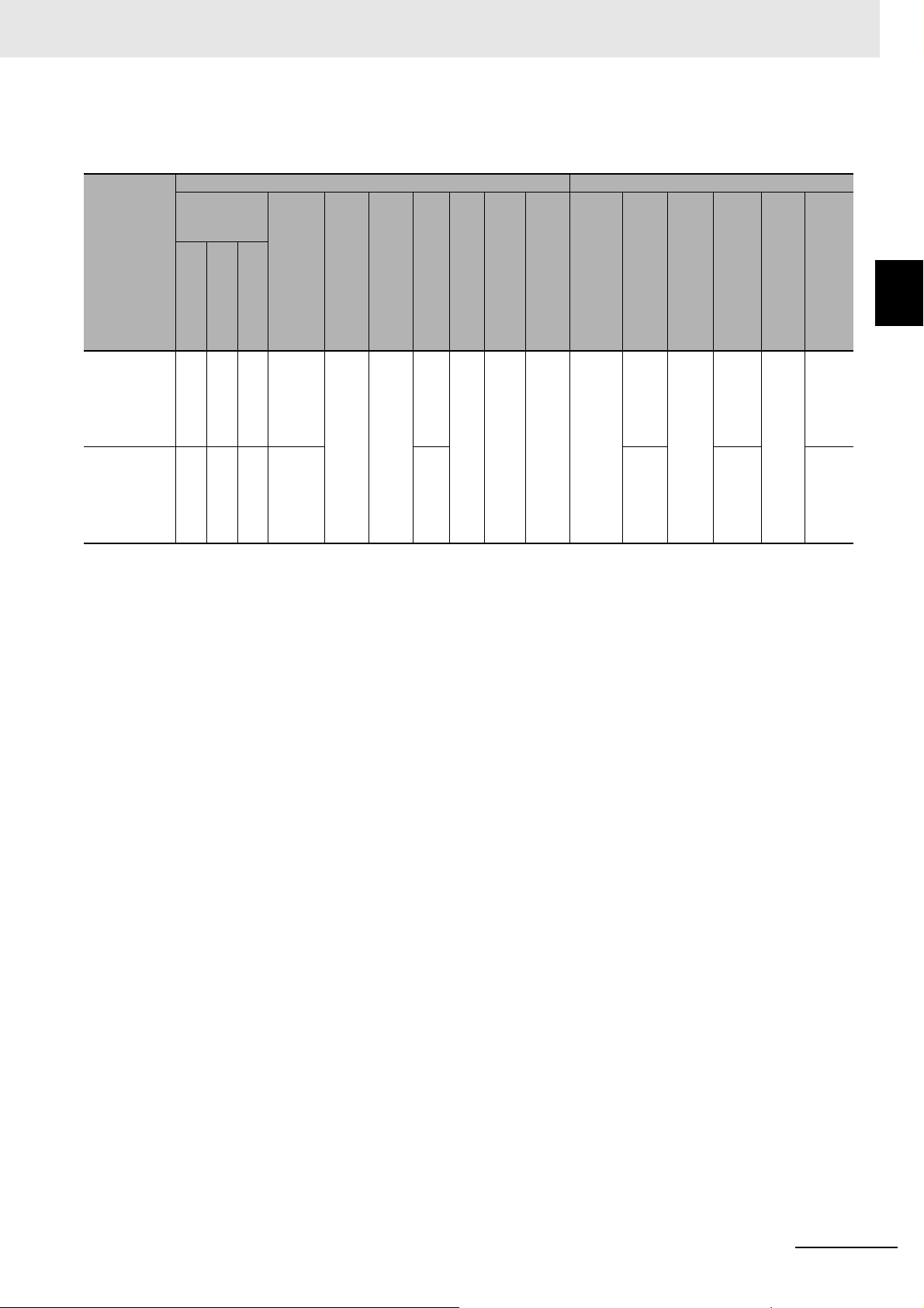
1 Data List
z Data List
Model
NX-MD6121-5
NX-MD6256-5
Unit configuration data Summary specifications
NX Unit power
consumption
[W]
Cou-
CPU
pler
1.00 0.70 1.00
1.10 0.75 1.10 40 110 PNP,
Con
trol
Cur-
rent
con-
sump-
tion
from
I/O
power
supply
[mA]
30
I/O
nt
[mA]
pow
Wei
er
ght
supp
[g]
ly
meth
od
105 30 2/2 1/1 16
nal
Input
curre
7Exter
Wid
th
[m
m]
I/O
data
size
[byt
e]
Num
ber
of I/O
entry
mapping
s
Number of
points
points,
16
points
Inter-
nal
I/O
com-
mon
NPN,
for
both
NPN/
PNP
for
both
NPN/
PNP
Maximum
load
current
0.5 A/
point,
2A/
Unit
Rated
volt-
age
12 to
24
VDC,
24
VDC
24
VDC,
24
VDC
I/O
refre
shin
g
meth
od
Sync
ON/
OFF
respo
nse
time
0.1/0.8
ms
max.,
20/400
μs
max.
0.5/1.0
ms
max.,
20/400
μ
s
max.
1-5 Digital I/O Units
1
1-5-3 Digital Mixed I/O Units
NX-series Data Reference Manual (W525)
1 - 25
Page 50

1 Data List
DC Input/Transistor Output Units (Fujitsu Connector, 30 mm Width)
z Items in the Summary Specifications
Number of points The number of output and input points provided by the Unit. The first value in this column is for out-
Internal I/O common This is the polarity that the Unit uses to connect to output and input devices.
Maximum load current The maximum output load current of the Unit.
Rated voltage The rated output voltage and rated input voltage of the Unit. The first value in this column is for out-
I/O refreshing method The I/O refreshing methods that are used by the Unit.
Item Description
put, and the latter is for input.
There are models with NPN and PNP connections. The first value in this column is for output, and
the latter is for input.
Specifications for each output point and for the Unit are described.
put, and the latter is for input.
Free-Run refreshing, synchronous I/O refreshing, output refreshing with specified time stamp and
input refreshing with input changed time are available.
z Data List
Model
NX-MD6121-6
ON/OFF response
time
NX Unit power
consumption
[W]
Cou-
pler
Con
trol
CPU
1.00 0.70 1.00
In the following table, the following abbreviations are used.
Free: Free-Run refreshing
Sync: Switching synchronous I/O refreshing and Free-Run refreshing
Specified time: Output refreshing with specified time stamp
Changed time: Input refreshing with input changed time
For outputs, the delay time for which data in the internal circuit is reflected in the state of output
elements of the Unit. For inputs, the delay time for which the status change of the input terminals
reaches the internal circuit of the Unit.
The input filter time is not included.
The first two values in this column are for output, and the latter two are for input.
Unit configuration data Summary specifications
Current
ent
I/O
pow
er
supp
ly
meth
od
nal
Wi
dth
[m
m]
I/O
data
size
[byte]
Wei
ght
[g]
95 30 2/2 1/1 16
Num-
ber
of I/O
entry
map-
pings
Number of
points
points,
16
points
Inter-
nal
I/O
com-
mon
NPN,
for
both
NPN/
PNP
Maxi-
mum
load
current
0.5 A/
point,
2A/
Unit
Rated
volt-
age
12 to
24
VDC,
24
VDC
con-
sump-
tion
from
I/O
power
sup-
ply
[mA]
30
Input
curr
[mA]
7Exter
I/O
refre
shin
g
meth
od
Sync
ON/
OFF
respo
nse
time
0.1/0.8
ms
max.,
20/400
µs
max.
1 - 26
NX-series Data Reference Manual (W525)
Page 51

1-6 Analog I/O Units
This section describes the data for Analog I/O Units.
1 Data List
1-6 Analog I/O Units
1-6-1 Analog Input Units
Analog Input Units (Screwless Clamping Terminal Block, 12 mm
Width)
z Items in the Summary Specifications
Item Description
Number of points The number of analog input points provided by the Unit.
Input range The input range of the Unit.
Resolution The resolution of converted values of the Unit.
Input method The analog signal input method provided by the Unit. Single-ended input and differential input are
available.
In the following table, the following abbreviations are used.
Single: Single-ended input
Diff: Differential input
I/O refreshing method The I/O refreshing methods that are used by the Unit.
Free-Run refreshing and synchronous I/O refreshing are available.
In the following table, the following abbreviations are used.
Free
:
Free-Run refreshing
: Switching
Sync
Conversion time The time required per input to convert analog input signals of the Unit to the converted values.
synchronous I/O refreshing
and
Free-Run refreshing
1
1-6-1 Analog Input Units
NX-series Data Reference Manual (W525)
1 - 27
Page 52

1 Data List
z Data List
NX Unit power
consumption
Model
CPU
NX-AD2203
NX-AD2204
NX-AD2208
NX-AD2603
NX-AD2604
NX-AD2608
NX-AD3203
NX-AD3204
NX-AD3208
NX-AD3603
NX-AD3604
NX-AD3608
NX-AD4203
NX-AD4204
NX-AD4208
NX-AD4603
NX-AD4604
NX-AD4608
1.25 0.90 1.25
1.35 1.05 1.35
1.25 0.90 1.25
1.30 0.95 1.30 1/
1.35 1.10 1.35
1.45 1.45 1/
1.40 1.05 1.40
1.45 1.10 1.45 1/
[W]
Cou-
pler
1.15
Con-
trol
Unit configuration data Summary specifications
Current
con-
sump-
tion
from I/O
power
supply
[mA]
No consumption
I/O
pow
Wei
er
ght
sup-
[g]
ply
met
hod
NX
70 12 4/0 1/0 2
bus
No
supply
NX
bus
No
supply
NX
bus
No
supply
NX
bus
No
supply
NX
bus
No
supply
NX
bus
No
supply
I/O
Wid
data
th
size
[m
[byte
m]
]
8/0 4
16/0 8
Num-
ber of
I/O
entry
map-
pings
Num
ber
of
poin
ts
point
s
point
s
point
s
Input
range
4 to 20 mA1/
-10 to
+10 V1/8000
4 to 20 mA1/
-10 to
+10 V1/8000
4 to 20 mA1/
-10 to
+10 V1/8000
Resolution
8000
1/
30000
1/
30000
8000
30000
30000
8000
30000
1/
30000
Input
meth
od
Single
Diff
Single
Diff
Single
Diff
Single
Diff
Single
Diff
Single
Diff
I/O
refresh
ing
metho
d
Free
Sync
Free
Sync
Free
Sync
Free
Sync
Free
Sync
Free
Sync
Conver
sion
time
250 μs
10 μs
250 μs
10 μs
250 μs
10 μs
250 μs
10 μs
250 μs
10 μs
250 μs
10 μs
1 - 28
NX-series Data Reference Manual (W525)
Page 53

1-6-2 High-speed Analog Input Units
High-speed Analog Input Units (Screwless Clamping Terminal
Block, 24 mm Width)
1 Data List
1-6 Analog I/O Units
z Items in the Summary Specifications
Item Description
Analog
input
section
Trigg er
input
section
I/O refreshing method The I/O refreshing methods that are used by the Unit.
Number of
points
Input range The input range of the Unit.
Resolution The resolution of converted values of the Unit.
Input
method
Conversion
time
Number of
points
Internal I/O
common
The number of analog input points provided by the Unit.
The analog signal input method provided by the Unit.
Only differential input method is available.
In the following table, the following abbreviation is used.
Diff: Differential input
The time required to convert analog input signals of the Unit to the converted values.
The number of trigger input points provided by the Unit.
The polarity of the input devices that are connected to the Unit.
There are models with NPN and PNP connections.
Only synchronous I/O refreshing method is available.
In the following table, the following abbreviation is used.
Sync: Synchronous I/O refreshing
1
1-6-2 High-speed Analog Input Units
z Data List
Unit configuration data Summary specifications
NX Unit
power con-
sumption
[W]
Model
CPU
NXHAD401
NXHAD402
*1. The input data size will increase if a number greater than 10 is set for the number of sampling in Ch Number of Samplings Setting.
For the Number of Samplings Setting or I/O data specification, refer to the NX-series Analog I/O Units User’s Manual for High-speed
Analog Input Units (Cat. No. W592).
*2. Depending on the input range, the resolution becomes as follows.
For -10 to 10 V and -5 to 5 V: 1/64000
For other ranges: 1/32000
3.30 2.95 30 NX
Cou
pler
Current
con-
sump-
tion from
I/O power
supply
[mA]
I/O
pow
Wei
er
sup
ply
met
hod
140 24 136/
bus
ght
[g]
Wi
dt
[m
m]
Num
ber
I/O
of I/O
data
size
[byte
]
*1
8
entry
map-
4/4 4
h
ping
s
Nu
mb
er
of
poi
nts
poin
ts
Analog input section
Re
Input range
-10 to 10 V
-5 to 5 V
0 to 10 V
0 to 5 V
1 to 5 V
0 to 20 mA
4 to 20 mA
sol
uti
on
*2
Inp
Con-
ut
ver-
met
sion
hod
time
Diff 5 µs
per
channel
Trigger
input sec-
tion
Nu
Inter-
mb
er
of
poi
nts
4
NPN Syn
poin
ts
PNP
nal
I/O
com-
mon
I/O
refr
esh-
ing
met
hod
c
NX-series Data Reference Manual (W525)
1 - 29
Page 54
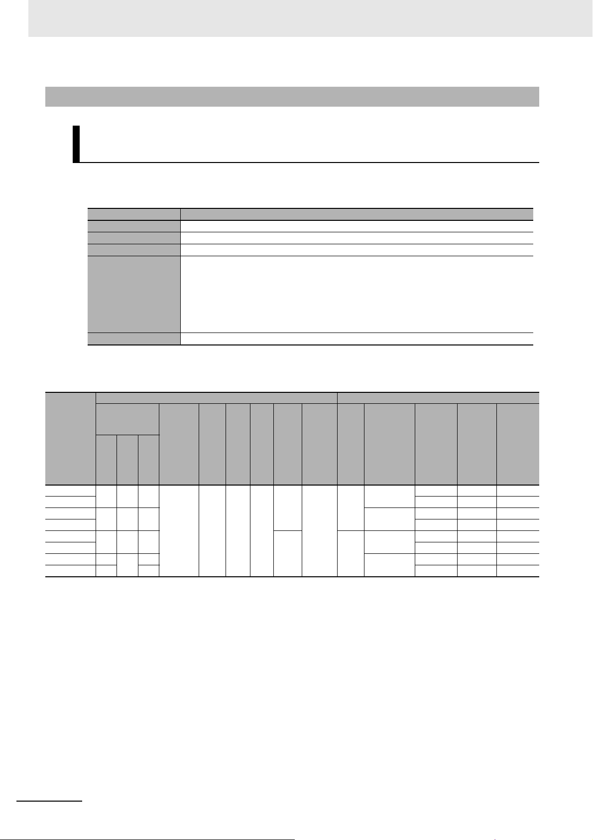
1 Data List
1-6-3 Analog Output Units
Analog Output Units (Screwless Clamping Terminal Block, 12 mm
Width)
z Items in the Summary Specifications
Item Description
Number of points The number of analog output points provided by the Unit.
Output range The output range of the Unit.
Resolution The resolution of converted values of the Unit.
I/O refreshing method The I/O refreshing methods that are used by the Unit.
Free-Run refreshing and synchronous I/O refreshing are available.
In the following table, the following abbreviations are used.
Free
:
Free-Run refreshing
: Switching
Sync
Conversion time The time required per output to convert analog output signals of the Unit to the converted values.
synchronous I/O refreshing
and
Free-Run refreshing.
Model
NX-DA2203
NX-DA2205
NX-DA2603
NX-DA2605
NX-DA3203
NX-DA3205
NX-DA3603
NX-DA3605
z Data List
Unit configuration data Summary specifications
NX Unit power
consumption
[W]
Cou-
CPU
pler
2.10 1.75 2.10
1.40 1.10 1.40 -10 to +10 V1/8000 Free
2.10 1.80 2.10 0/8 4
1.35 1.25 1.35 -10 to +10 V1/8000 Free
1.60 1.60 1/30000 Sync
Con-
trol
Current
con-
sump-
tion
from I/O
power
supply
[mA]
No consumption
I/O
pow
Wei
er
ght
sup-
[g]
ply
met
hod
NX
70 12 0/4 0/1 2
bus
Wid
th
[m
m]
I/O
data
size
[byte
Num-
ber of
entry
map-
]
pings
I/O
Num
ber
poin
point
s
point
s
Output
of
ts
range
4 to 20 mA 1/8000 Free
4 to 20 mA 1/8000 Free
Resolu-
tion
1/30000 Sync
1/30000 Sync
1/30000 Sync
I/O
refreshi
ng
method
Conver-
sion
time
250 μs
10 μs
250 μs
10 μs
250 μs
10 μs
250 μs
10 μs
1 - 30
NX-series Data Reference Manual (W525)
Page 55
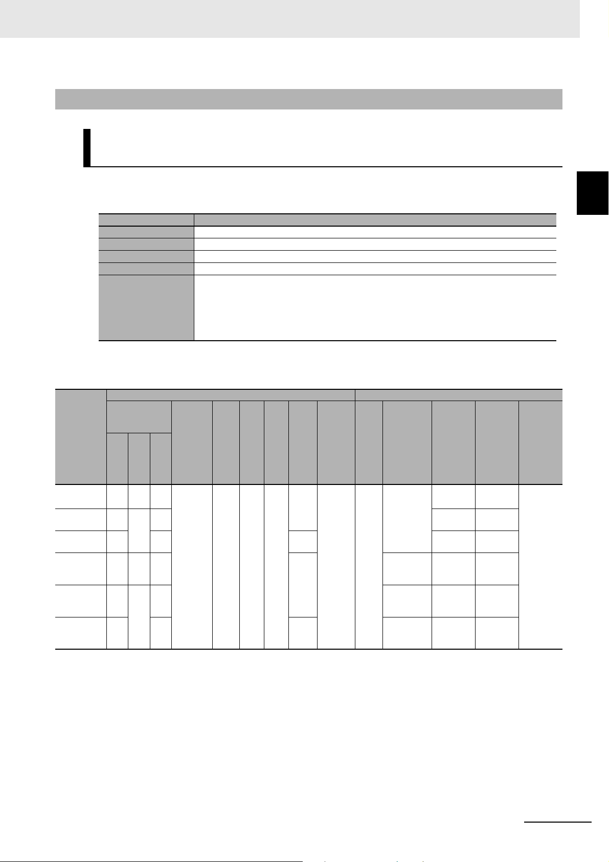
1-6-4 Temperature Input Units
Temperature Input Units (Screwless Clamping Terminal Block, 12
mm Width)
1 Data List
1-6 Analog I/O Units
z Items in the Summary Specifications
Item Description
Number of points The number of temperature input points provided by the Unit.
Input type The temperature input type of the Unit.
Conversion time The time required to convert temperature input signals of the Unit to temperature data.
Resolution The resolution of the measured values for the Unit. It is defined in °C.
I/O refreshing method The I/O refreshing methods that are used by the Unit.
Only Free-Run refreshing is available.
In the following table, the following abbreviation is used.
Free: Free-Run refreshing
z Data List
Unit configuration data Summary specifications
NX Unit power
consumption
CPU
[W]
Cou-
pler
Model
NX-TS2101 1.25 0.90 1.25 No con-
NX-TS2102 1.15 0.80 1.15 10 ms 0.01°C
NX-TS2104 0.95 0.95 8/0 60 ms 0.001°C
NX-TS2201 1.25 0.90 1.25 4/0 Resis-
NX-TS2202 1.15 0.75 1.15 Resis-
NX-TS2204 0.90 0.90 8/0 Resis-
*1. The resolution is 0.2°C max. when the input type is R, S, or W.
Con-
trol
Current
con-
sump-
tion
from I/O
power
supply
[mA]
sumption
I/O
pow
er
sup-
ply
met
hod
No
supply
Wid
Wei
th
ght
[m
[g]
70 12 4/0 1/0 2
m]
[byte
I/O
data
size
]
Number of
I/O
entry
map-
pings
Num
ber
of
poin
ts
point
s
Input type
Thermocouple
tance thermometer
tance thermometer
tance thermometer
Conver-
sion
time
250 ms 0.1°C
250 ms 0.1°C
10 ms 0.01°C
60 ms 0.001°C
Resolu-
tion
max.
max.
max.
max.
max.
max.
1
1-6-4 Temperature Input Units
I/O
refreshin
g
method
Free
*1
NX-series Data Reference Manual (W525)
1 - 31
Page 56
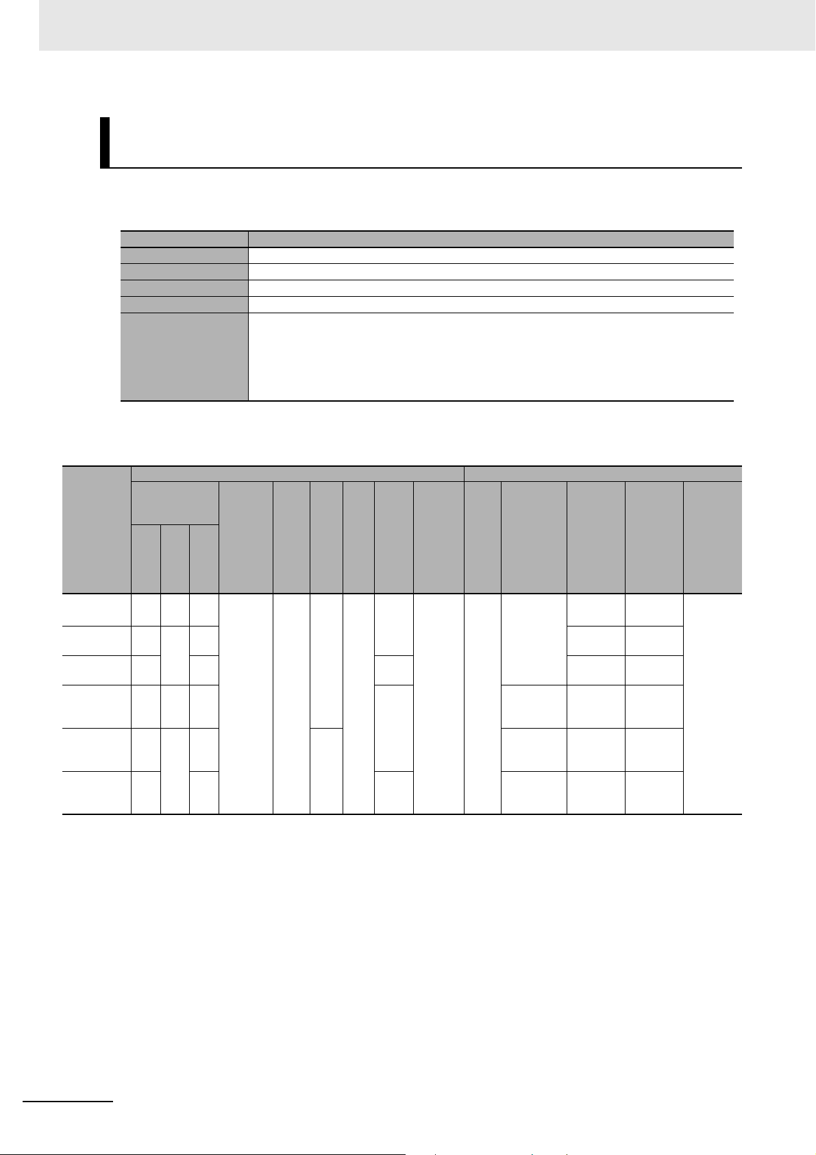
1 Data List
Temperature Input Units (Screwless Clamping Terminal Block, 24
mm Width)
z Items in the Summary Specifications
Number of points The number of temperature input points provided by the Unit.
Input type The temperature input type of the Unit.
Conversion time The time required to convert temperature input signals of the Unit to temperature data.
Resolution The resolution of the measured values for the Unit. It is defined in °C.
I/O refreshing method The I/O refreshing methods that are used by the Unit.
z Data List
Item Description
Only Free-Run refreshing is available.
In the following table, the following abbreviation is used.
Free: Free-Run refreshing
Unit configuration data Summary specifications
NX Unit power
consumption
CPU
[W]
Cou-
pler
Model
NX-TS3101 1.75 1.30 1.75 No con-
NX-TS3102 1.55 1.10 1.55 10 ms 0.01°C
NX-TS3104 1.45 1.45 16/0 60 ms 0.001°C
NX-TS3201 1.75 1.30 1.75 8/0 Resis-
NX-TS3202 1.50 1.05 1.50 130 Resis-
NX-TS3204 1.45 1.45 16/0 Resis-
*1. The resolution is 0.2°C max. when the input type is R, S, or W.
Con-
trol
Current
con-
sump-
tion
from I/O
power
supply
[mA]
sumption
I/O
pow
er
sup-
ply
met
hod
No
supply
Wid
Wei
th
ght
[m
[g]
140 24 8/0 1/0 4
m]
[byte
I/O
data
size
]
Number of
I/O
entry
map-
pings
Num
ber
of
poin
ts
point
s
Input type
Thermocouple
tance thermometer
tance thermometer
tance thermometer
Conver-
sion
time
250 ms 0.1°C
250 ms 0.1°C
10 ms 0.01°C
60 ms 0.001°C
Resolu-
tion
max.
max.
max.
max.
max.
max.
I/O
refreshin
g
method
Free
*1
1 - 32
NX-series Data Reference Manual (W525)
Page 57

1-6-5 Heater Burnout Detection Units
This section describes the data for Heater Burnout Detection Units.
z Items in the Summary Specifications
1 Data List
1-6 Analog I/O Units
Item Description
CT input section
Control output section
I/O refreshing method The I/O refreshing methods that are used by the Unit.
Number of
points
Maximum
heater current
Number of
points
Internal I/O
common
Maximum load
current
Rated voltage The rated voltage of the control outputs on the Unit.
The number of CT inputs supported by the Unit.
The maximum value of the current that can flow through the heater power line on the primary side of the CT that is connected to the Unit.
The number of control output signals supported by the Unit.
The polarity that the Unit uses to connect to output devices. There are models with NPN
and PNP connections.
The maximum load current for control outputs from the Unit. A specification is given for
each control output and each Unit.
Only Free-Run refreshing is available.
In the following table, the following abbreviation is used.
Free: Free-Run refreshing
z Data List
Unit configuration data Summary specifications
NX Unit
I/O
CT input sec-
tion
Max-
s
imu
m
heat
er
current
50 A AC4
Num-
ber of
point
points
Control output section
Number of
point
s
points
Inter-
com-
NPN 0.1 A/
nal
I/O
mon
Maxi
mum
load
curre
point,
0.4 A/
Unit
Rate
volta
nt
12 to
24
VDC
VDC
power
consump-
tion [W]
Model
CPU
NX-HB3101 1.05 0.75 20 NX
NX-HB3201 PNP 24
Cou-
pler
Current
consump-
tion from
I/O power
supply
[mA]
I/O
pow
Weig
er
sup-
ply
met
hod
bus
Widt
ht
h
[g]
[mm]
[byte
70 12 42/18 2/2 4
I/O
data
size
]
Num-
ber of
entry
map-
pings
ge
1
1-6-5 Heater Burnout Detection Units
I/O
refre
shin
g
meth
d
od
Free
NX-series Data Reference Manual (W525)
1 - 33
Page 58

1 Data List
1-7 Position Interface Units
This section describes the data for Position Interface Units.
1-7-1 Incremental Encoder Input Units
z Items in the Summary Specifications
Item Description
Number of channels The number of encoder input channels of the Unit.
Number of external
inputs
Maximum response
frequency
I/O refreshing method The I/O refreshing methods that are used by the Unit.
The number of external inputs of the Unit.
The maximum frequency of the encoder input.
Free-Run refreshing, synchronous I/O refreshing and task period prioritized refreshing are available.
In the following table, the following abbreviations are used.
:
Free-Run refreshing
Free
Sync
: Switching
Task: Switching Free-Run refreshing, synchronous I/O refreshing and task period prioritized
refreshing
synchronous I/O refreshing
and
Free-Run refreshing
z Data List
Unit configuration data Summary specifications
NX Unit
power
Model
NX-EC0112
NX-EC0122
NX-EC0132
NX-EC0142
NX-EC0212
NX-EC0222
consump-
tion [W]
CPU
1.15 0.85 0 NX bus 70 12 18/4 1/1 1 (NPN) 3 (NPN) 500 kHz Sync or
1.30 0.95 1 (PNP) 3 (PNP)
1.25 0.95
1.50 1.05 3 (PNP)
1.15 0.85 0 70 12 36/8 2/2 2 (NPN) None 500 kHz
1.30 0.95 2 (PNP)
*1. "Sync" is for Units with unit version 1.1 or earlier. "Task" is for Units with unit version 1.2 or later.
*2. When you use the 5-V power supply for an encoder, be sure to include that current too. Refer to the NX-series Position
Interface Units User's Manual (Cat. No. W524-E1-04 or later) for information on how to convert a 5-V power supply current
consumption to a 24-V power supply current consumption.
Cou-
pler
Current
consump-
tion from
I/O power
supply
[mA]
*2
30
I/O
power
supply
method
Num-
I/O
Weig
Widt
ht
h
[g]
[mm]
[byte]
130 24 18/4 1/1 1 3 (NPN) 4 MHz
data
size
ber of
entry
map-
pings
I/O
Number
of
channel
s
Number
of exter-
nal
inputs
Maxi-
mum
respons
e fre-
quency
I/O
refresh
ing
metho
d
*1
Ta sk
Remar
ks
24 V
voltage
input
Line
receive
r input
24 V
voltage
input
1 - 34
NX-series Data Reference Manual (W525)
Page 59
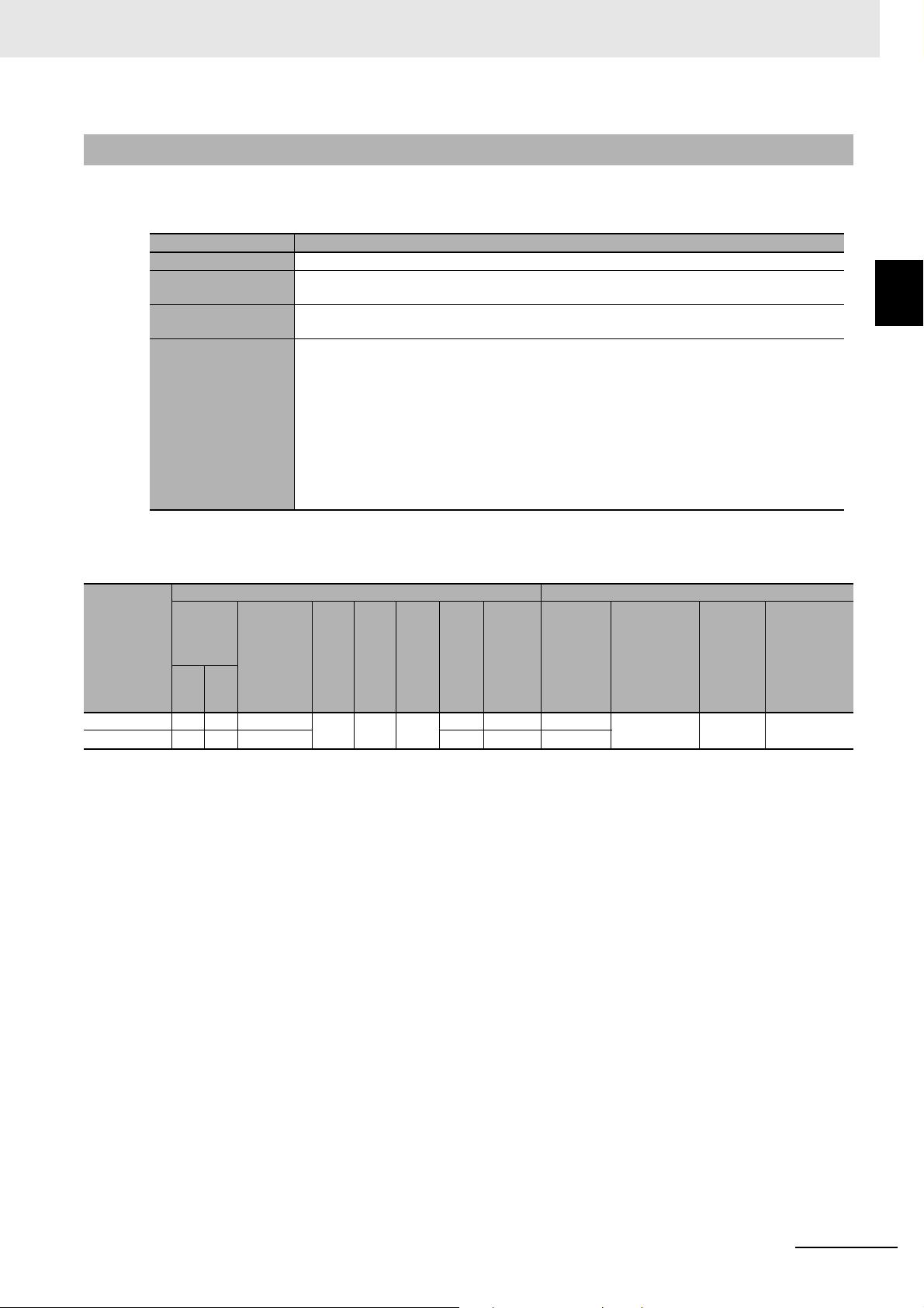
1-7-2 SSI Input Units
z Items in the Summary Specifications
Item Description
Number of channels The number of SSI communications channels of the Unit.
Number of external
inputs
Maximum baud rate
I/O refreshing method The I/O refreshing methods that are used by the Unit.
The number of external inputs of the Unit.
The maximum baud rate (Maximum frequency of synchronous clock) that you can use for SSI
communications.
Free-Run refreshing, synchronous I/O refreshing and task period prioritized refreshing are available.
In the following table, the following abbreviations are used.
Free
Sync
Task: Switching Free-Run refreshing, synchronous I/O refreshing and task period prioritized
refreshing
:
Free-Run refreshing
: Switching
synchronous I/O refreshing
and
Free-Run refreshing
1 Data List
1-7 Position Interface Units
1
1-7-2 SSI Input Units
z Data List
Unit configuration data Summary specifications
Model
NX-ECS112
NX-ECS212
NX Unit
power
consump-
tion [W]
Cou-
CPU
1.20 0.85 20 NX
1.25 0.90 30 20/0 2/0 2
pler
Current
consump-
tion from
I/O power
supply
[mA]
*1. "Sync" is for Units with unit version 1.1 or earlier. "Task" is for Units with unit version 1.2 or later.
I/O
pow
Weig
Widt
er
sup-
met
hod
bus
ht
[g]
ply
[mm]
65 12 10/0 1/0 1 None 2 MHz Sync or
data
h
size
[byte
I/O
]
Num-
ber of
I/O
entry
map-
pings
Number
of
channels
Number of
external
inputs
Maxi-
mum
baud
rate
I/O
refreshing
method
*1
Ta sk
NX-series Data Reference Manual (W525)
1 - 35
Page 60

1 Data List
1-7-3 Pulse Output Units
Pulse Output Units (Screwless Clamping Terminal Block, 12 mm
Width)
z Items in the Summary Specifications
Item Description
Number of channels The number of pulse output channels of the Unit.
Number of external
inputs
Number of external
outputs
Maximum pulse output speed
I/O refreshing method The I/O refreshing methods that are used by the Unit.
The number of external inputs of the Unit.
The number of external outputs of the Unit.
The maximum pulse output speed.
Synchronous I/O refreshing and task period prioritized refreshing are available.
In the following table, the following abbreviations are used.
Sync: Synchronous I/O refreshing
Task: Switching synchronous I/O refreshing and task period prioritized refreshing
*1. For Pulse Output Units, Free-Run refreshing is not available.
z Data List
Unit configuration data Summary specifications
Model
NX-PG0112
NX-PG0122
NX Unit
power
consump-
tion [W]
Cou-
CPU
1.15 0.80 20 NX
1.30 0.90 1
pler
Current
consump-
tion from
I/O power
supply
[mA]
*1. "Sync" is for Units with unit version 1.1 or earlier. "Task" is for Units with unit version 1.2 or later.
I/O
pow
Weig
er
sup-
met
hod
bus
ht
[g]
ply
[mm]
70 12 18/141/1 1
Widt
h
data
size
[byte
I/O
]
Num-
ber of
I/O
entry
map-
pings
nal
Numb
er of
exter-
nal
outputs
er of
els
Numb
er of
exter-
inputs
Numb
chann
(NPN)2 (NPN)1 (NPN)
(PNP)2(PNP)1(PNP)
Maxi-
mum
pulse
out-
put
speed
500
kpps
*1
I/O
refresh
ing
metho
d
Sync or
Ta sk
Remar
ks
Open
*1
collecto
r output
1 - 36
NX-series Data Reference Manual (W525)
Page 61

Pulse Output Units (MIL Connector, 30 mm Width)
z Items in the Summary Specifications
Item Description
Number of channels The number of pulse output channels of the Unit.
Number of external
inputs
Number of external
outputs
Maximum pulse output speed
I/O refreshing method The I/O refreshing methods that are used by the Unit.
*1. For Pulse Output Units, Free-Run refreshing is not available.
The number of external inputs of the Unit. The number of inputs for each pulse output channel.
The number of external outputs of the Unit. The number of outputs for each pulse output channel.
The maximum pulse output speed.
Synchronous I/O refreshing and task period prioritized refreshing are available.
In the following table, the following abbreviations are used.
Sync: Synchronous I/O refreshing
Task: Switching synchronous I/O refreshing and task period prioritized refreshing
1 Data List
1-7 Position Interface Units
1
1-7-3 Pulse Output Units
*1
z Data List
Unit configuration data Summary specifications
Model
NX-PG0232-5
NX-PG0242-5
NX-PG0332-5
NX-PG0342-5
NX Unit
power
consump-
tion [W]
CPU
1.55 1.20 50 Exter
1.65 1.30
Current
consump-
tion from
I/O power
pler
supply
[mA]
50/CN
50/CN
Cou-
1.20 50 110 5
1.30
*1. The current consumption from I/O power supply for one MIL connector.
I/O
pow
Weig
Widt
er
sup-
met
hod
nal
*1
*1
ht
[g]
ply
[mm]
110 30 34/26 2/2 2 5
150 68/52 4/4 4 5
150 5
data
h
size
[byte
I/O
]
Num-
ber of
I/O
entry
map-
pings
Numb
er of
chann
els
Numb
er of
exter-
nal
inputs
inputs
per
channel
(NPN)
inputs
per
channel
(PNP)
inputs
per
channel
(NPN)
inputs
per
channel
(PNP)
Numb
er of
exter-
nal
out-
puts
3
inputs
per
channel
(NPN)
3
inputs
per
channel
(PNP)
3
inputs
per
channel
(NPN)
3
inputs
per
channel
(PNP)
Maximum
pulse
speed
4MppsTa sk
out-
put
refresh
metho
I/O
ing
d
Remar
ks
Line
driver
output
NX-series Data Reference Manual (W525)
1 - 37
Page 62

1 Data List
1-8 Communications Interface Units
This section describes the data for Communications Interface Units.
z Items in the Summary Specifications
Item Description
External connection terminals The shape of the external connection terminals of the Unit.
Port specifications The serial communications port specifications of the Unit.
Number of ports The number of serial ports of the Unit.
Communications protocol The serial communications protocol supported by the Unit.
I/O refreshing method The I/O refreshing methods that are used by the Unit.
Only Free-Run refreshing is available.
In this table, the following abbreviation is used.
Free: Free-Run refreshing
Model
NX-CIF101
NX-CIF105
NX-CIF210
z Data List
Unit configuration data Summary specifications
NX Unit
power
consump-
tion [W]
CPU
1.10 0.90
1.65 1.45 69 RS-422A/4
1.15 0.95 91 30 60/56 2/2 D-sub con-
Cou-
pler
Current
consump-
tion from
I/O power
supply
[mA]
No consumption
I/O
pow
Wei
Widt
er
ght
sup-
[g]
ply
meth
od
No
66 12 30/28 1/1 Screwless
supply
h
[mm]
data
[byte
I/O
size
]
Num-
ber of
I/O
entry
map-
pings
External
connec-
tion termi-
nals
clamping
terminal
block
nector
Port spec-
RS-232C 1 No-prot
85
RS-232C 2
ifications
Num-
ber of
ports
Com-
muni-
cation
s pro-
tocol
ocol
I/O
refres
hing
metho
d
Free
1 - 38
NX-series Data Reference Manual (W525)
Page 63

1-9 Load Cell Input Unit
This section describes the data for the Load Cell Input Unit.
z Items in the Summary Specifications
Item Description
Number of points The number of load cell input points provided by the Unit.
Conversion cycle The time required to convert load cell input signals of the Unit to measurement values.
Load cell excitation
voltage
Input range The input range of the Unit.
I/O refreshing method The I/O refreshing methods that are used by the Unit.
The excitation voltage that is supplied from the Unit to the load cell. The output current of the load
cell excitation voltage that the Unit can supply is also listed.
Free-Run refreshing, synchronous I/O refreshing and task period prioritized refreshing are available.
1 Data List
1-9 Load Cell Input Unit
1
z Data List
NX Unit
power
Model
NX-RS1201 2.05 1.70 No con-
consump-
tion [W]
CPU
Cou-
pler
Current
consump-
tion from
I/O power
supply
[mA]
sumption
In the following table, the following abbreviations are used.
Free: Free-Run refreshing
Sync: Switching synchronous I/O refreshing and Free-Run refreshing
Task: Switching Free-Run refreshing, synchronous I/O refreshing and task period prioritized
refreshing
Unit configuration data Summary specifications
I/O
pow
Wei
er
ght
sup-
[g]
ply
meth
od
No
70 12 8/2 1/1 1
supply
Widt
h
[mm]
data
[byte
I/O
size
]
Num-
ber of
I/O
entry
map-
pings
Num-
point
point
Con-
ber
ver-
of
sion
cycle
s
125 µs 5 VDC ± 10%,
Load cell
excitation
voltage
Output current: 60 mA
max.
Input
range
-5.0 to
5.0
mV/V
I/O
refresh
ing
metho
d
Ta sk
NX-series Data Reference Manual (W525)
1 - 39
Page 64
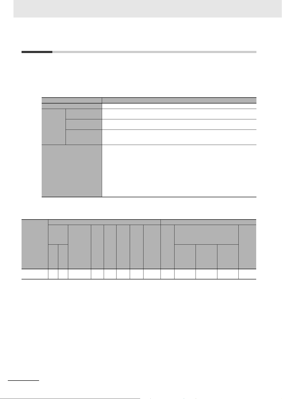
1 Data List
1-10 IO-Link Master Unit
This section describes the data for the IO-Link Master Unit.
z Items in the Summary Specifications
Item Description
Number of ports The number of ports for I/O connection on the Unit.
Internal I/O
common
I/O refreshing method The I/O refreshing methods that are used by the Unit.
Digital inputs (in
SIO (DI) Mode)
Digital outputs (in
SIO (DO) Mode)
Digital inputs for
pin 2 (in IO-Link
Mode)
The polarity that the Unit uses to connect to input devices in SIO (DI) Mode.
The polarity that the Unit uses to connect to output devices in SIO (DO) Mode.
The polarity that the Unit uses to connect to input devices for digital inputs for pin 2 in
IO-Link Mode.
Free-Run refreshing, synchronous I/O refreshing and task period prioritized refreshing are
available.
In the following table, the following abbreviations are used.
Free: Free-Run refreshing
Sync: Switching synchronous I/O refreshing and Free-Run refreshing
Task: Switching Free-Run refreshing, synchronous I/O refreshing and task period prioritized refreshing
z Data List
Unit configuration data Summary specifications
NX Unit
power
consump-
Model
NX-ILM400 1.05 0.80 50 NX
tion [W]
CPU
Cou-
pler
Current
consump-
tion from
I/O power
supply
[mA]
*1. The default values are different depend on the unit version.
Version 1.0: 14/8
Version 1.1 or later: 16/10
I/O
pow
er
sup-
ply
meth
od
bus
Wei
ght
[g]
[mm]
67 12
Widt
h
I/O
data
size
[byte
]
*1
Num-
ber of
entry
map-
pings
4/4 4 PNP PNP PNP Free
I/O
Num-
ber
of
ports
Internal I/O common
Digital
inputs (in
SIO (DI)
Mode)
Digital
outputs
(in SIO
(DO)
Mode)
Digital
inputs for
pin 2 (in
IO-Link
Mode)
refresh
ing
metho
I/O
d
1 - 40
NX-series Data Reference Manual (W525)
Page 65

1-11 Temperature Control Units
This section describes the data for Temperature Control Units.
z Items in the Summary Specifications
1 Data List
1-11 Temperature Control Units
Item Description
Number of channels,
Input type,
Conversion time
Output Output type The control outputs that are provided by the Unit.
Number of output points per
channel
Number of CT input points per
channel
Control type The control types that are provided by the Unit.
I/O refreshing method The I/O refreshing methods that are used by the Unit.
• Number of channels
The number of control loops that are provided on the Unit.
• Input type
The input type of the temperature input that are provided on the Unit.
In the following table, the following abbreviations are used.
Universal: Thermocouple and Platinum resistance thermometer
• Conversion time
The time required to convert temperature input signals of the Unit to temperature data.
In the following table, the following abbreviation is used.
Voltage: Voltage output (for driving SSR)
Current: Linear current output
The number of output points per channel on the Unit.
The number of CT inputs per channel on the Unit.
In the following table, the following abbreviation is used.
Standard: Standard control
Heating/cooling: Heating/cooling control
Only Free-Run refreshing is available.
1
*1
*1. One temperature input is provided for each channel. For example, the Unit with two channels has two inputs.
NX-series Data Reference Manual (W525)
In the following table, the following abbreviation is used.
Free: Free-Run refreshing
1 - 41
Page 66
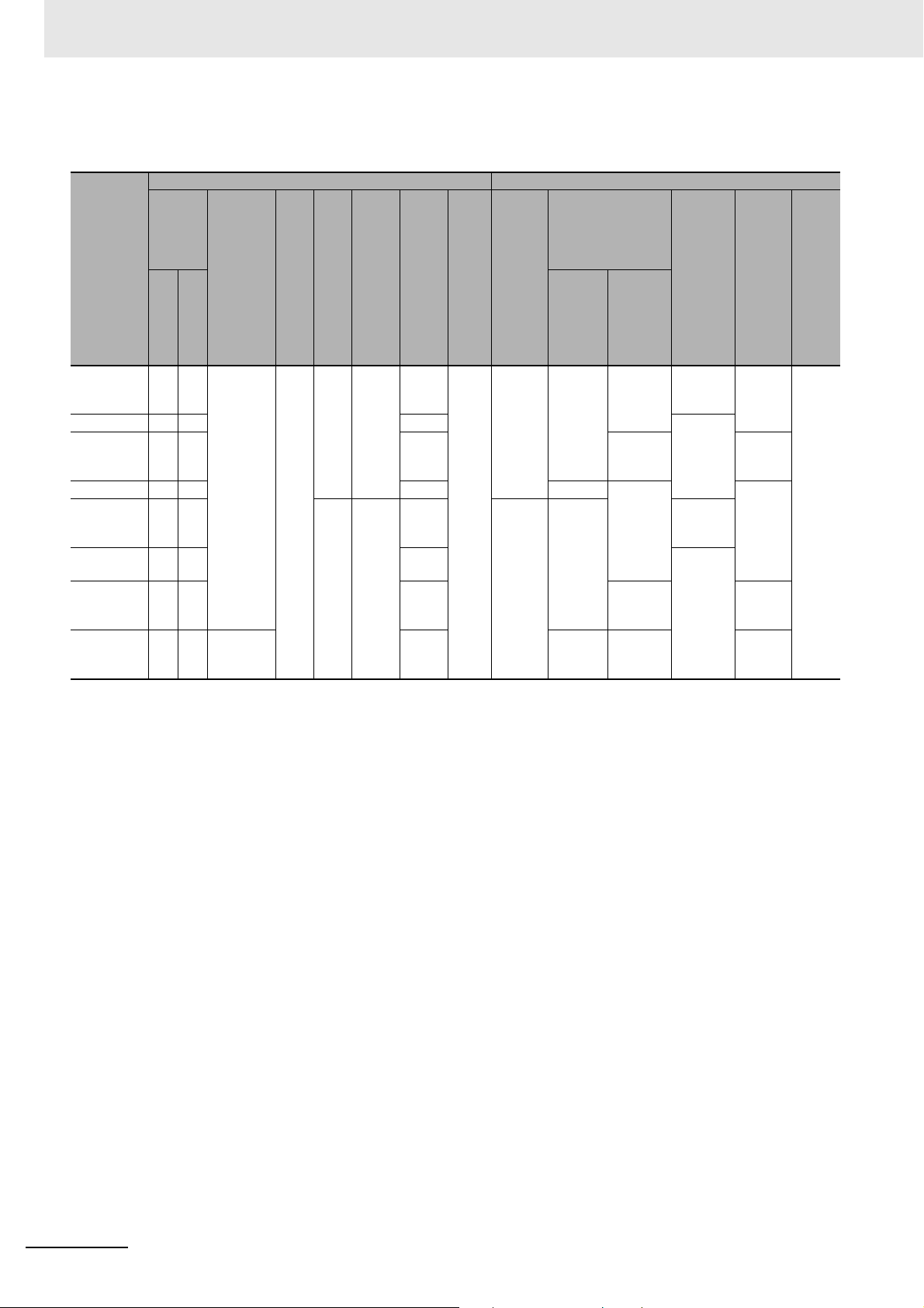
1 Data List
z Data List
Unit configuration data Summary specifications
NX Unit
power
con-
sumption
Model
NX-TC2405 1.45 1.10 20 NX
NX-TC2406 1.25 0.95 50/84 None
NX-TC2407 1.30 1.00 74/96 2 points
NX-TC2408 1.25 0.95 50/84 Current 1 point
NX-TC3405 1.80 1.35 140 24 146/1
NX-TC3406 1.70 1.25 98/16
NX-TC3407 1.75 1.30 146/1
NX-TC3408 1.65 1.25 30 98/16
[W]
CPU
Cou
pler
Current
con-
sumption
from
I/O power
supply
[mA]
I/O
pow
Wei
er
sup-
ply
met
hod
bus
Width
ght
[mm]
[g]
75 12 74/92 1/1 2 chan-
[byte]
84
8
92
8
I/O
data
size
Num
entry
map-
ping
ber
of
I/O
s
Number of
chan-
nels,
Input
type,
Con-
version
time
nels,
Universal, 50
ms
4 channels,
Universal, 50
ms
Output
Number
Output
type
Voltage 1 point
Voltage 1 point
Current 1 point
of out-
put
points
per
channel
per
channel
per
channel
per
channel
2 points
per
channel
per
channel
Number
of CT
input
points
per
channel
1 point
per
channel
per
channel
None
Con-
trol
type
Standard
Heating/cool
ing
Standard
Heating/cool
ing
Standard
I/O
refres
h
ing
meth
od
Free
1 - 42
NX-series Data Reference Manual (W525)
Page 67
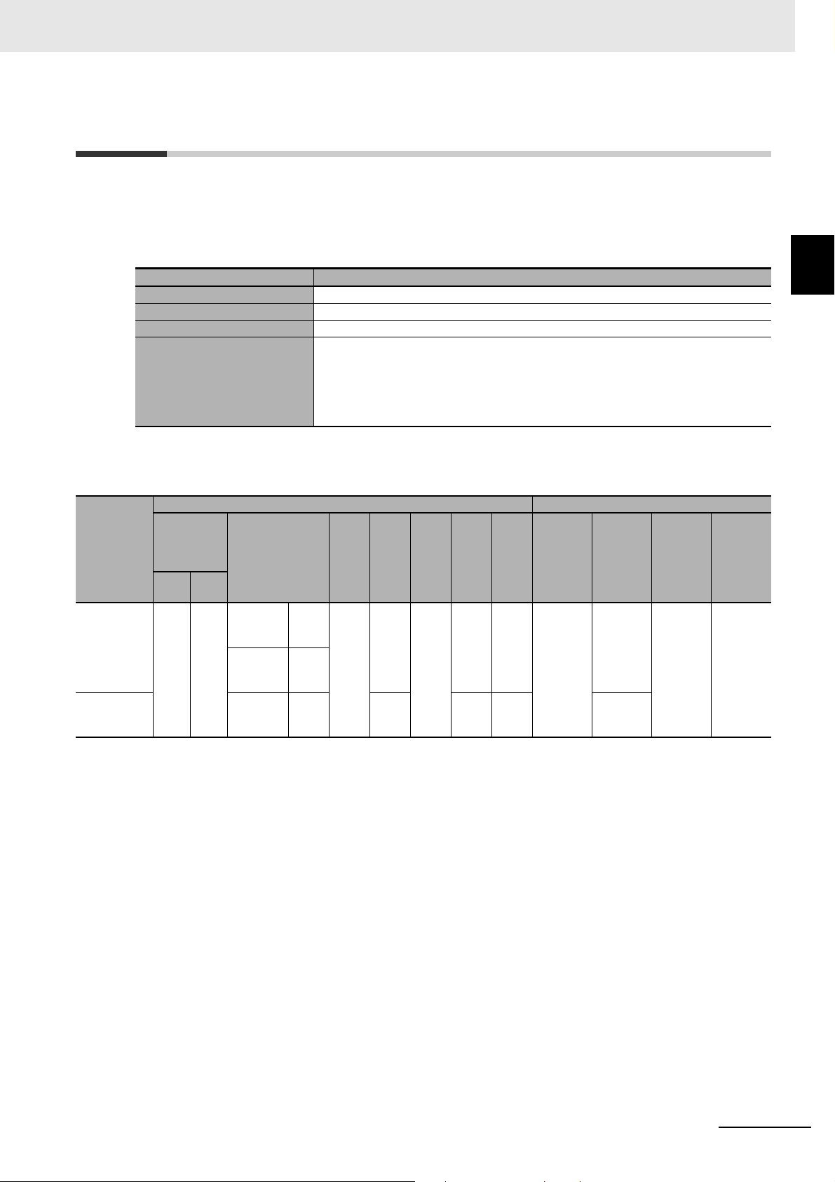
1 Data List
1-12 RFID Units
This section describes the data for RFID Units.
z Items in the Summary Specifications
Item Description
External connection terminals The shape of the external connection terminals of the Unit.
Number of connected antennas The number of antennas connected to the Unit.
Communications protocol The communications protocol supported by the Unit.
I/O refreshing method The I/O refreshing methods that are used by the Unit.
Only Free-Run refreshing is available.
In the following table, the following abbreviations are used.
Free: Free-Run refreshing
z Data List
Unit configuration data Summary specifications
NX Unit
Model
NX-V680C1 1.00 0.90 V680-HA
NX-V680C2 V680-HA
power con-
sumption
[W]
Cou-
CPU
pler
Current con-
sumption from
I/O power supply
[mA]
210 NX
63 connection
V680-H0
1-V2 connection
63 connection
250
380 130 56/60 2/2 2
I/O
powe
Weig
r sup-
ply
meth
od
bus
Width
ht [g]
[mm]
120 30 28/30 1/1 FG termi-
I/O
data
size
[byte]
Num-
ber of
I/O
entry
map-
pings
External
connec-
tion ter-
minals
nal block
(1 terminal)
Number
of con-
nected
antennas
1 ISO/IEC1
Commu-
nica-
tions
protocol
8000-3
(15693)
1-12 RFID Units
1
I/O
refresh-
ing
method
Free
NX-series Data Reference Manual (W525)
1 - 43
Page 68

1 Data List
1-13 System Units
This section describes the data for System Units.
1-13-1 Additional NX Unit Power Supply Unit
z Items in the Summary Specifications
Item Description
Rated power supply
voltage
NX Unit power supply
capacity
z Data List
The rated voltage that is supplied to the Unit.
The amount of power that the Unit can supply to the NX Units. The power consumption of the Unit
from the NX Unit power supply is not included.
Unit configuration data Summary specifications
NX Unit power
Model
NX-PD1000
*1. The NX Unit power supply capacity is restricted by the temperature or installation orientation. For details, refer to A-1 NX Unit Power
Supply and I/O Power Supply Capacity on page A-2.
consumption
[W]
Cou-
CPU
0.85 0.45 0.85
Con-
pler
trol
Current
consump-
tion from
I/O power
supply
[mA]
No consumption
I/O
powe
r sup-
meth
No
supply
Weig
Widt
ply
od
ht
[g]
[mm]
65 12 0/0 0/0 24 VDC 10 W
I/O
data
h
size
[byte]
Num-
ber of
I/O
entry
map-
pings
Rated power
supply volt-
age
NX Unit power supply
capacity
*1
1-13-2 Additional I/O Power Supply Unit
z Items in the Summary Specifications
Item Description
Rated power supply
voltage
Maximum current of
I/O power supply
The rated voltage of the I/O power supply that is supplied to the Unit.
The maximum value of the current supplied from the I/O power supply that the Unit can supply to
the NX Units through the NX bus connectors.
1 - 44
NX-series Data Reference Manual (W525)
Page 69
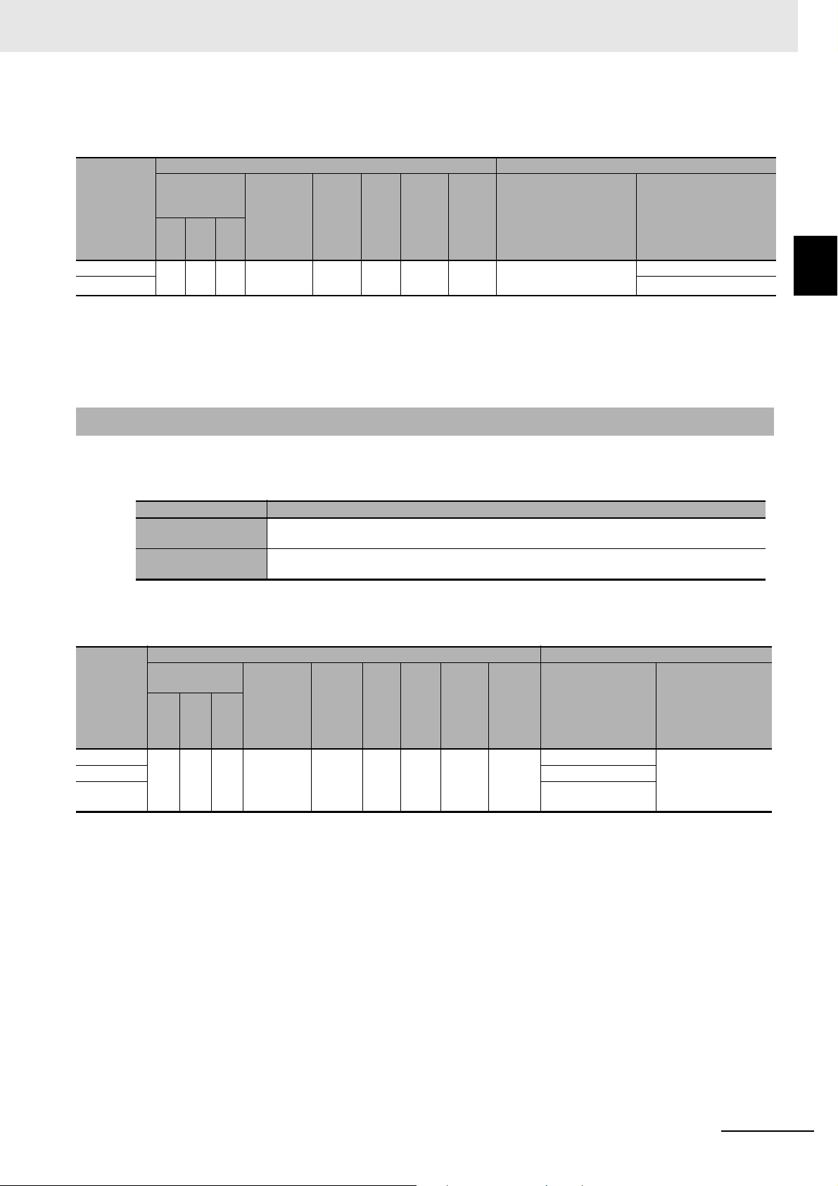
1 Data List
z Data List
Unit configuration data Summary specifications
Model
NX-PF0630
NX-PF0730
NX Unit power
consumption
[W]
Cou-
CPU
pler
0.85 0.45 0.85 10 65 12 0/0 0/0 5 to 24 VDC 4 A
Con-
trol
Current
consump-
tion from
I/O power
supply
[mA]
Weigh
t [g]
Widt
h
[mm]
I/O
data
size
[byte]
Num-
ber of
I/O
entry
map-
pings
Rated power supply
voltage
Maximum current of I/O
power supply
*1
10 A
*1. When an Additional I/O Power Supply Unit is connected to the CPU Rack of a CPU Unit, the maximum I/O power supply
current value may be smaller than that of the Additional I/O Power Supply Unit. For example, the maximum I/O power
supply current for the CPU Rack of an NX1P2 CPU Unit is 4 A. Refer to the hardware user’s manual for the CPU Unit to
which NX Units are connected for information on the restrictions for the CPU Rack of the CPU Unit.
1-13-3 I/O Power Supply Connection Unit
z Items in the Summary Specifications
Item Description
Number of I/O power
supply terminals
Current capacity of I/O
power supply terminal
The type (IOV/IOG) and number of I/O power supply terminals of the Unit.
The current capacity of the I/O power supply terminals of the Unit.
1-13 System Units
1
1-13-3 I/O Power Supply Connection Unit
Model
NX-PC0020
NX-PC0010
NX-PC0030
z Data List
NX Unit power
consumption [W]
Cou-
CPU
0.85 0.45 0.85
Con-
pler
trol
Unit configuration data Summary specifications
Current
consump-
tion from
I/O power
supply
[mA]
No consumption
I/O
Wei
ght
[g]
Widt
[mm]
power
supply
metho
d
NX bus 65 12 0/0 0/0 IOV: 16 terminals 4 A/terminal
I/O
data
h
size
[byte]
Num-
ber of
I/O
entry
map-
pings
Number of I/O
power supply ter-
minals
IOG: 16 terminals
IOV: 8 terminals
IOG: 8 terminals
Current capacity of
I/O power supply
terminal
NX-series Data Reference Manual (W525)
1 - 45
Page 70
1 Data List
1-13-4 Shield Connection Unit
z Items in the Summary Specifications
Item Description
Model
NX-TBX01
Number of shield terminals
z Data List
NX Unit power
consumption [W]
Cou-
pler
Con-
trol
CPU
0.85 0.45 0.85
The number of terminals of the SHLD terminal of the Unit.
Unit configuration data Summary specifications
Current
consump-
tion from
I/O power
supply
[mA]
No consumption
I/O
powe
r sup-
ply
meth
od
No
supply
Number
Wei
Widt
ght
[g]
[mm]
65 12 0/0 0/0 14 terminals
I/O
data
h
size
[byte]
of I/O
entry
map-
pings
Number of shield terminals
1 - 46
NX-series Data Reference Manual (W525)
Page 71
1-14 Safety Control Units
This section describes the data for Safety Control Units.
1 Data List
1-14 Safety Control Units
1-14-1 Safety CPU Unit
z Items in the Summary Specifications
Item Description
Model
NX-SL3300
NX-SL3500
NX-SL5500
NX-SL5700
Maximum number of
safety I/O points
Program capacity This is the capacity of the user program in the Unit.
Number of safety master connections
Number of safety I/O
connections
I/O refreshing method The I/O refreshing methods that are used by the Unit.
z Data List
NX Unit power con-
sumption [W]
Cou-
pler
Con-
trol
CPU
1.25 0.90 ---
3.35 --- 3.35 130 0/0 to
This is the number of safety I/O points that the Unit can control.
This is the number of safety master connections that the Unit can have through Safety over EtherCAT (FSoE).
You can connect one Safety I/O Unit for each safety master connection.
This is the number of safety I/O connections for the Unit. The value is the total number of CIP
Safety originator connections, CIP Safety target connections, and FSoE master connections.
Only Free-Run refreshing is available.
In the following table, the following abbreviation is used.
Free: Free-Run refreshing
Unit configuration data Summary specifications
Curre
nt
consu
mptio
n from
I/O
power
supply
[mA]
No
consumption
I/O
powe
r sup-
ply
meth
od
No
supply
Wei
Widt
ght
[g]
[mm]
75 30 0/0 to
I/O
data
h
size
[byte]
512/
512
0/0 to
1024/
1024
2048/
2048
0/0 to
2048/
2048
I/O
Maxim
um
numbe
r of
safety
I/O
points
points
1024
points
points
points
Num-
ber of
entry
map-
pings
2/2 256
3/3 1024
3/3 2032
Numbe
Progra
m
capacit
y
512 KB 32 --- Free
2048
KB
2048 KB--- 128
4096 KB--- 254
r of
safety
master
connec
tions
128 ---
Num-
ber of
safety
I/O
con-
nec-
tions
refresh
ing
metho
1
1-14-1 Safety CPU Unit
I/O
d
NX-series Data Reference Manual (W525)
1 - 47
Page 72
1 Data List
1-14-2 Safety Input Units
z Items in the Summary Specifications
Item Description
Number of safety
input points
Number of test output
points
Internal I/O common This is the polarity that the Unit uses to connect to input devices. There are
Rated input voltage This is the rated input voltage of the Unit.
OMRON Special
Safety Input Devices
Number of safety
slave connections
I/O refreshing method The I/O refreshing methods that are used by the Unit.
This is the number of safety input points on the Unit.
This is the number of test output points on the Unit. The test output points are used with the safety
input terminals.
models with NPN and PNP connections.
This tells whether the Unit supports the connection of OMRON Special Safety Input Devices (D40A
Non-contact Door Switches, E3FS Single Beam Safety Sensors, etc.).
In the following table, the following abbreviations are used.
Yes: Can be connected
No: Cannot be connected
This is the number of safety slave connections that the Unit can have through Safety over EtherCAT (FSoE). You can connect to one Safety CPU Unit for each safety slave connection.
Only Free-Run refreshing is available.
Model
NXSID800
NXSIH400
In the following table, the following abbreviation is used.
Free: Free-Run refreshing
z Data List
Unit configuration data Summary specifications
NX Unit power
consumption
[W]
Cou-
CPU
pler
1.10 0.75 1.10 20 3.0 NX
1.10 0.70 1.10 4.5 8/8 4
Con-
trol
Curre
nt
consu
mptio
n from
I/O
power
supply
[mA]
Input
current
[mA]
I/O
powe
Wei
r sup-
ply
meth
od
bus
Width
ght
[mm]
[g]
70 12 10/102/2 8
I/O
data
size
[byte]
Number of
I/O
entry
map-
pings
Numb
er of
safety
input
point
s
point
s
point
s
Numb
er of
test
outpu
t
point
s
2
point
s
Intern
Rated
al I/O
input
comm
voltag
on
PNP 24
VDC
OMR
ON
Speci
al
Safet
y
e
Input
Devic
es
No 1 Free
Ye s
Numb
er of
safety
slave
conne
ctions
I/O
refre
shing
meth
od
1 - 48
NX-series Data Reference Manual (W525)
Page 73

1-14-3 Safety Output Units
z Items in the Summary Specifications
Item Description
Number of safety
output points
Internal I/O common This is the polarity that the Unit uses to connect to output devices. There are models with NPN and
Maximum load current This is the maximum load current for outputs on the Unit. A specification is given for each output
Rated voltage This is the rated voltage of the outputs on the Unit.
Number of safety
slave connections
I/O refreshing method The I/O refreshing methods that are used by the Unit.
This is the number of safety output points on the Unit.
PNP connections.
and each Unit.
This is the number of safety slave connections that the Unit can have through Safety over EtherCAT (FSoE). You can connect to one Safety CPU Unit for each safety slave connection.
Only Free-Run refreshing is available.
In the following table, the following abbreviation is used.
Free: Free-Run refreshing
1 Data List
1-14 Safety Control Units
1
1-14-3 Safety Output Units
Model
NXSOD400
NXSOH200
z Data List
Unit configuration data Summary specifications
NX Unit power
consumption
[W]
Cou-
CPU
pler
1.10 0.75 1.10 60 NX
1.05 0.70 1.05 40 2
Con-
trol
Current
consu
mption
from
I/O
power
supply
[mA]
I/O
powe
r
Weig
sup-
ply
meth
od
bus
Width
ht [g]
[mm]
[byte]
65 12 8/8 2/2 4
I/O
data
size
Num-
ber of
entry
map-
pings
I/O
Numb
er of
safety
outpu
t
point
s
points
points
Intern
al I/O
com
mon
PNP
Maximu
m load
current
0.5 A/
point, 2 A/
Unit
2.0 A/
point,
4.0 A/Unit
°C
,
at 40
2.5 A/Unit
°C
at 55
Rated
volta
ge
24
VDC
Numbe
r of
safety
slave
connec
tions
1Free
I/O
refresh
ing
metho
d
NX-series Data Reference Manual (W525)
1 - 49
Page 74

1 Data List
1 - 50
NX-series Data Reference Manual (W525)
Page 75

Appendices
This section describes NX Unit power supply and I/O power supply capacity, NX Units
that have restrictions in the communications cycles, and specific values of NX Units for
calculating performance.
A-1 NX Unit Power Supply and I/O Power Supply Capacity . . . . . . . . . . . . . . . A-2
A-1-1 EtherCAT Coupler Unit . . . . . . . . . . . . . . . . . . . . . . . . . . . . . . . . . . . . . . . . . . . A-2
A-1-2 EtherNet/IP Coupler Unit . . . . . . . . . . . . . . . . . . . . . . . . . . . . . . . . . . . . . . . . . A-3
A-1-3 Additional NX Unit Power Supply Unit . . . . . . . . . . . . . . . . . . . . . . . . . . . . . . . A-4
A-1-4 Additional I/O Power Supply Unit . . . . . . . . . . . . . . . . . . . . . . . . . . . . . . . . . . . A-4
A-2 NX Units That Have Restrictions in Communications Cycles . . . . . . . . . . A-5
A-2-1 NX Units That Have Restrictions in Communications Cycles in DC Mode . . . . A-5
A-2-2 NX Units That Have Restrictions in Communications Cycles in Free-Run
A-3 Specific Values of NX Units for Performance Calculation . . . . . . . . . . . . . A-6
A-3-1 Specific Values of NX Units Operate with Synchronous I/O Refreshing . . . . . . A-6
A-3-2 Specific Values of NX Units Operate with Task Period Prioritized Refreshing A-10
A-3-3 Specific Values of NX Units Operate with Time Stamp Refreshing . . . . . . . . A-12
A-3-4 Specific Values of NX Units Operate with Free-Run Refreshing . . . . . . . . . . A-13
A-4 List of Screwless Clamping Terminal Block Models . . . . . . . . . . . . . . . . A-16
A-4-1 Model Notation . . . . . . . . . . . . . . . . . . . . . . . . . . . . . . . . . . . . . . . . . . . . . . . . A-16
A-4-2 List of Terminal Block Models . . . . . . . . . . . . . . . . . . . . . . . . . . . . . . . . . . . . . A-16
A-4-3 Applicable Screwless Clamping Terminal Blocks for Each Unit Model . . . . . . A-17
A-5 Version Information with CPU Units . . . . . . . . . . . . . . . . . . . . . . . . . . . . . . A-20
A-5-1 Relationship between Unit Versions of Units . . . . . . . . . . . . . . . . . . . . . . . . . A-20
A-5-2 Support Functions of the CPU Units and Restrictions on the NX Units . . . . . A-27
A-6 Version Information with Communications Coupler Units . . . . . . . . . . . A-29
A-6-1 Connection to an EtherCAT Coupler Unit . . . . . . . . . . . . . . . . . . . . . . . . . . . . A-29
A-6-2 Connection to an EtherNet/IP Coupler Unit . . . . . . . . . . . . . . . . . . . . . . . . . . A-38
A-6-3 Support Functions of the Communications Coupler Units and
A-7 Version Information with Communication Control Units . . . . . . . . . . . . . A-52
A-7-1 Relationship between Unit Versions of Units . . . . . . . . . . . . . . . . . . . . . . . . . A-52
A-7-2 Support Functions of the Communication Control Units and
A
Mode . . . . . . . . . . . . . . . . . . . . . . . . . . . . . . . . . . . . . . . . . . . . . . . . . . . . . . . . . A-5
Restrictions on the NX Units . . . . . . . . . . . . . . . . . . . . . . . . . . . . . . . . . . . . . . A-47
Restrictions on the NX Units . . . . . . . . . . . . . . . . . . . . . . . . . . . . . . . . . . . . . . A-56
NX-series Data Reference Manual (W525)
A - 1
Page 76

Appendices
NX Unit
power supply (W)
For 10 W output, 40°C
Ambient operating temperature (°C)
60555045403020100
10
8
4
2
0
6
12
For 8.5 W output, 55°C
NX Unit
power supply (W)
For 10 W output, 40°C
Ambient operating temperature (°C)
60555045403020100
10
8
4
2
0
6
12
For 6.0 W output, 55°C
A-1 NX Unit Power Supply and I/O Power
Supply Capacity
Each Unit that supplies NX Unit power or I/O power to the CPU Rack or Slave Terminal has different
restrictions on the installation orientation and maximum output capacity. This section describes the
restrictions on each Unit.
The Units shown in this section are only the ones with certain restrictions.
A-1-1 EtherCAT Coupler Unit
z NX-ECC201/ECC202/ECC203
Item Specification
NX Unit power supply capacity 10 W max. (Refer to Installation orientation and restrictions for details.)
Installation orientation and restrictions
Installation orientation: Possible in 6 orientations.
Restrictions:
• For upright installation
• For any installation other than upright
A - 2
NX-series Data Reference Manual (W525)
Page 77

A-1-2 EtherNet/IP Coupler Unit
NX Unit
power supply (W)
For 10 W output, 40°C
Ambient operating temperature (°C)
60555045403020100
10
8
4
2
0
6
12
For 8.5 W output, 55°C
z NX-EIC202
Item Specification
NX Unit power supply capacity 10 W max. (Refer to Installation orientation and restrictions for details.)
Maximum current of I/O power supply
Installation orientation and restrictions
10 A (Refer to Installation orientation and restrictions for details.)
Installation orientation: Possible in 6 orientations.
Restrictions:
Appendices
A-1 NX Unit Power Supply and I/O Power
Supply Capacity
• For upright installation
The following restrictions apply to the NX Unit power supply.
• For any installation other than upright
The following restrictions apply respectively to the NX Unit power supply and I/O
power supply.
NX Unit
power supply (W)
12
10
For 10 W output, 40°C
A
A-1-2 EtherNet/IP Coupler Unit
NX-series Data Reference Manual (W525)
8
6
4
2
0
Ambient operating temperature (°C)
I/O power supply (A)
12
10
8
6
4
2
0
Ambient operating temperature (°C)
For 6.0 W output, 55°C
60555045403020100
For 10 A current, 45°C
For 6 A current, 55°C
60555045403020100
A - 3
Page 78

Appendices
NX Unit
power supply (W)
For 10 W output, 40°C
Ambient operating temperature (°C)
60555045403020100
10
8
4
2
0
6
12
For 8.5 W output, 55°C
NX Unit
power supply (W)
For 10 W output, 40°C
Ambient operating temperature (°C)
60555045403020100
10
8
4
2
0
6
12
For 6.0 W output, 55°C
A-1-3 Additional NX Unit Power Supply Unit
z NX-PD1000
Item Specification
NX Unit power supply capacity 10 W max. (Refer to Installation orientation and restrictions for details.)
Installation orientation and restrictions
Installation orientation:
• Connected to a CPU Unit or Communication Control Unit
Possible in upright installation.
• Connected to a Communications Coupler Unit
Possible in 6 orientations.
Restrictions: As shown in the following.
• For upright installation
A-1-4 Additional I/O Power Supply Unit
• For any installation other than upright
When this Unit is used on the CPU Rack of the NX1P2 CPU Unit, the following items must be 4 A or
lower regardless of the Unit model.
• Maximum current of I/O power supply
• Current capacity of I/O power supply terminals
A - 4
NX-series Data Reference Manual (W525)
Page 79

Appendices
A-2 NX Units That Have Restrictions in
A-2 NX Units That Have Restrictions in
Communications Cycles
This section describes the NX Units that have restrictions in the communications cycles in DC Mode
and Free-Run Mode for EtherCAT Slave Terminals that you can set.
A-2-1 NX Units That Have Restrictions in Communications Cycles in
DC Mode
The following table gives the NX Units that have restrictions in the communications cycles in DC Mode
for EtherCAT Slave Terminals that you can set. For information on the communications cycles that you
can set, refer to Refresh Cycles in the user's manuals for the NX Units.
NX Units User's Manual
Position Interface Units NX-series Position Interface Units User's Manual
(Cat. No. W524-E1-06 or later)
Load Cell Input Unit NX-series Load Cell Input Unit User's Manual (Cat. No.
W565)
High-speed Analog Input Units NX-series Analog I/O Units User’s Manual for
High-speed Analog Input Units (Cat. No. W592)
Communications Cycles
A
A-2-1 NX Units That Have Restrictions in Communications Cycles in DC Mode
A-2-2 NX Units That Have Restrictions in Communications Cycles in
Free-Run Mode
The following table gives the NX Units that have restrictions in the communications cycles in Free-Run
Mode for EtherCAT Slave Terminals that you can set. For information on the communications cycles
that you can set, refer to Refresh Cycles in the user's manuals for the NX Units.
NX Units User's Manual
Position Interface Units NX-series Position Interface Units User's Manual
(Cat. No. W524-E1-06 or later)
NX-series Data Reference Manual (W525)
A - 5
Page 80
Appendices
A-3 Specific Values of NX Units for Perfor-
mance Calculation
This section describes the specific values of NX Units used for calculating the I/O response times of NX
Units connected to the CPU Unit or the Communication Control Unit and the process data communications performance of EtherCAT Slave Terminals.
Refer to the NJ/NX-series CPU Unit Software User’s Manual (Cat. No. W501) for details on the I/O
response times of NX Units connected to the CPU Unit.
Refer to the user’s manual for the connected Communications Coupler Unit for details on calculating
the process data communications performance of Slave Terminals.
Refer to the user’s manual for the Communication Control Unit for details on the I/O response times of
NX Units connected to the Communication Control Unit.
Refer to the user's manuals for the individual NX Units for further information if specific values for your
NX Units are not provided in this manual. The refreshing methods that you can use depend on the Unit
to which the NX Unit is connected. For available refreshing methods, refer to the user’s manual for the
CPU Unit, Communications Coupler Unit, or Communication Control Unit to which the NX Unit is connected.
A-3-1 Specific Values of NX Units Operate with Synchronous I/O
Refreshing
The following table gives specific values for each element of NX Units that operate with synchronous
I/O refreshing.
z Input Data Processing Time of NX Unit (Tnx-InProc)
NX Units
Type Model
Digital Input Units Models support synchroAnalog Input Units 0 [μs] −
Digital Mixed I/O Units 0 [μs] The value for digital inputs.
Incremental Encoder
Input Units
SSI Input Units 65 [μs] −
Pulse Output Units NX-PG0122
Load Cell Input Unit NX-RS1201 65 [µs] −
High-speed Analog
Input Units
*1. Pulse Output Units process status and other input data. Therefore, if there are Pulse Output Units that op-
erate with synchronous I/O refreshing in the configuration, they must be included in the Tmax-InProc calculation regardless of whether the external inputs are used.
nous I/O refreshing
/-PG0112
NX-PG0232-5
/-PG0242-5
NX-PG0332-5
/-PG0342-5
NX-HAD401
/-HAD402
Tnx-InProc Remarks
0 [μs] −
85 [μs] The value for pulse inputs and exter-
nal inputs.
45 [μs] The values for status and other input
data processing and for external
21 [μs]
31 [μs]
30 [μs] The value for analog inputs.
inputs.
*1
A - 6
NX-series Data Reference Manual (W525)
Page 81

z Output Data Processing Time of NX Unit (Tnx-OutProc)
Appendices
A-3 Specific Values of NX Units for Perfor-
NX Units
Type Model
Digital Output Units Models support synchroDigital Mixed I/O Units 0 [μs] The value for digital outputs.
Analog Output Units Conversion time
Incremental Encoder
Input Units
SSI Input Units 40 [μs]
Pulse Output Units NX-PG0122
Load Cell Input Unit NX-RS1201 35 [µs] This is the value for operation com-
High-speed Analog
Input Units
*1. If only a definition is given in the above table, refer to the data of the NX Units in Section 1 Data List or the
manuals for the specific NX Units for the values of the items.
*2. Incremental Encoder Input Units and SSI Input Units perform processing for command values and other
output data. Therefore, if there are any of these Units that operate with synchronous I/O refreshing in the
configuration, they must be included in the Tmax-OutProc calculations.
*3. The Load Cell Input Unit performs processing for operation commands and other output data. Therefore, if
there is a Load Cell Input Unit that operates with synchronous I/O refreshing in the configuration, the Unit
must be included in the Tmax-OutProc calculations.
*4. High-speed Analog Input Units perform processing for operation commands and other output data. There-
fore, if there are High-speed Analog Input Units that operate with synchronous I/O refreshing in the configuration, the Units must be included in the Tmax-OutProc calculations.
nous I/O refreshing
/-PG0112
NX-PG0232-5
/-PG0242-5
NX-PG0332-5
/-PG0342-5
NX-HAD401
/-HAD402
Tnx-OutProc
0 [μs] −
× Number of
points
40 [μs] This is the value for command val-
70 [μs] The value for pulse outputs and
95 [μs]
160 [μs]
15 [μs] This is the value for operation com-
*1
The conversion time and number of
points depend on the model of the
Unit.
ues and other output data process-
*2
ing.
external outputs.
mands and other output data pro-
cessing.
mands and other output data processing.
Remarks
*3
*4
mance Calculation
A
A-3-1 Specific Values of NX Units Operate with Synchronous I/O Refreshing
NX-series Data Reference Manual (W525)
A - 7
Page 82

Appendices
z Input Delay Time of NX Unit (Tnx-Indelay)
NX Units
Type Model
Digital Input Units Models support synchro-
nous I/O refreshing
Digital Mixed I/O Units ON/OFF
Analog Input Units Conversion time
Incremental Encoder
Input Units
SSI Input Units 0 [μs] −
Pulse Output Units NX-PG0122
/-PG0112
NX-PG0232-5
/-PG0242-5
/-PG0332-5
/-PG0342-5
Load Cell Input Unit NX-RS1201 0 [µs] −
High-speed Analog
Input Units
*1. If only a definition is given in the above table, refer to the data of the NX Units in Section 1 Data List or the
manuals for the specific NX Units for the values of the items.
*2. The value for external input 0 is the same as one given in the above table even if it is used in the model
with a line receiver input.
NX-HAD401
/-HAD402
Tnx-Indelay
ON/OFF
response time +
Input filter time
response time +
Input filter time
× Number of
points
0 [μs] The value for pulse inputs and exter-
0 [μs] This is the value for external inputs.
0 [µs] The value for external inputs 0 and
ON/OFF
response time
0 [μs] The value for analog inputs.
*1
The ON/OFF response time
depends on the model of the Unit.
You can set the input filter time for
each Unit.
This is applicable to the digital
inputs.
The ON/OFF response time
depends on the model of the Unit.
You can set the input filter time for
each Unit.
The conversion time and number of
points depend on the model of the
Unit.
nal inputs.
The ON/OFF response time of the
external inputs is included in
Tnx-InProc.
1. The ON/OFF response time of
external inputs 0 and 1 is included in
Tnx-InProc.
This is applicable to external inputs 2
through 4.
Remarks
*2
A - 8
NX-series Data Reference Manual (W525)
Page 83

z Output Delay Time of NX Unit (Tnx-Outdelay)
Appendices
A-3 Specific Values of NX Units for Perfor-
NX Units
Type Model
Digital Output Units Models support synchro-
nous I/O refreshing
Digital Mixed I/O Units ON/OFF
Analog Output Units 0 [μs] −
Pulse Output Units NX-PG0122
/-PG0112
NX-PG0232-5
/-PG0332-5
NX-PG0242-5
/-PG0342-5
*1. If only a definition is given in the above table, refer to the data of the NX Units in Section 1 Data List or the
manuals for the specific NX Units for the values of the items.
Tnx-Outdelay
ON/OFF
response time
response time
0 [μs] The value for pulse outputs and
0 [µs] The value for pulse outputs and
ON/OFF
response time
0 [µs] The value for pulse outputs.
ON/OFF
response time
*1
The ON/OFF response time
depends on the model of the Unit.
This is applicable to the digital outputs.
The ON/OFF response time
depends on the model of the Unit.
external outputs. The ON/OFF
response time of the external outputs is included in Tnx-OutProc.
external output 0. The ON/OFF
response time of external output 0 is
included in Tnx-OutProc.
This is applicable to external outputs
1 and 2.
This is applicable to external outputs. The ON/OFF response time
depends on the output port.
Remarks
mance Calculation
A
A-3-1 Specific Values of NX Units Operate with Synchronous I/O Refreshing
NX-series Data Reference Manual (W525)
A - 9
Page 84

Appendices
A-3-2 Specific Values of NX Units Operate with Task Period Prioritized
Refreshing
The following table gives specific values for each element of NX Units that operate with input prioritized
refreshing or output prioritized refreshing for task period prioritized refreshing.
z Input Data Processing Time of NX Unit (Tnx-InProc)
NX Units
Type Model
Incremental Encoder
Input Units
SSI Input Units
Load Cell Input Unit
*1. The Units operate with input prioritized refreshing.
*1
*1
Models support task
period prioritized refreshing
*1
NX-RS1201 65 [µs] −
Tnx-InProc Remarks
85 [μs] The value for pulse inputs and exter-
nal inputs.
65 [μs] −
z Output Data Processing Time of NX Unit (Tnx-OutProc)
NX Units
Type Model
*1
Pulse Output Units
*1. The Units operate with output prioritized refreshing.
NX-PG0122
/-PG0112
NX-PG0232-5
/-PG0242-5
NX-PG0332-5
/-PG0342-5
Tnx-OutProc Remarks
70 [μs] The value for pulse outputs and
external outputs.
95 [μs]
160 [μs]
z Input Delay Time of NX Unit (Tnx-Indelay)
NX Units
Type Model
Incremental Encoder
*1
Units
SSI Input Units
Load Cell Input Unit
*1. The Units operate with input prioritized refreshing.
*1
Models support task
period prioritized refreshing
*1
NX-RS1201 0 [µs] −
Tnx-Indelay Remarks
0 [μs] The value for pulse inputs and exter-
nal inputs.
0 [μs] −
A - 10
NX-series Data Reference Manual (W525)
Page 85

z Output Delay Time of NX Unit (Tnx-Outdelay)
Appendices
A-3 Specific Values of NX Units for Perfor-
NX Units
Type Model
*1
Pulse Output Units
*1. The Units operate with output prioritized refreshing.
NX-PG0122
/-PG0112
NX-PG0232-5
/-PG0332-5
NX-PG0242-5
/-PG0342-5
Tnx-Outdelay Remarks
0 [μs] The same value applies to external
outputs. The ON/OFF response time
of the external outputs is included in
Tnx-OutProc.
0 [µs] The value for pulse outputs and
external output 0. The ON/OFF
response time of external output 0 is
included in Tnx-OutProc.
ON/OFF
response time
0 [µs] The value for pulse outputs.
ON/OFF
response time
This is applicable to external outputs
1 and 2.
This is applicable to external out-
puts. The ON/OFF response time
depends on the output port.
mance Calculation
A
A-3-2 Specific Values of NX Units Operate with Task Period Prioritized Refreshing
NX-series Data Reference Manual (W525)
A - 11
Page 86
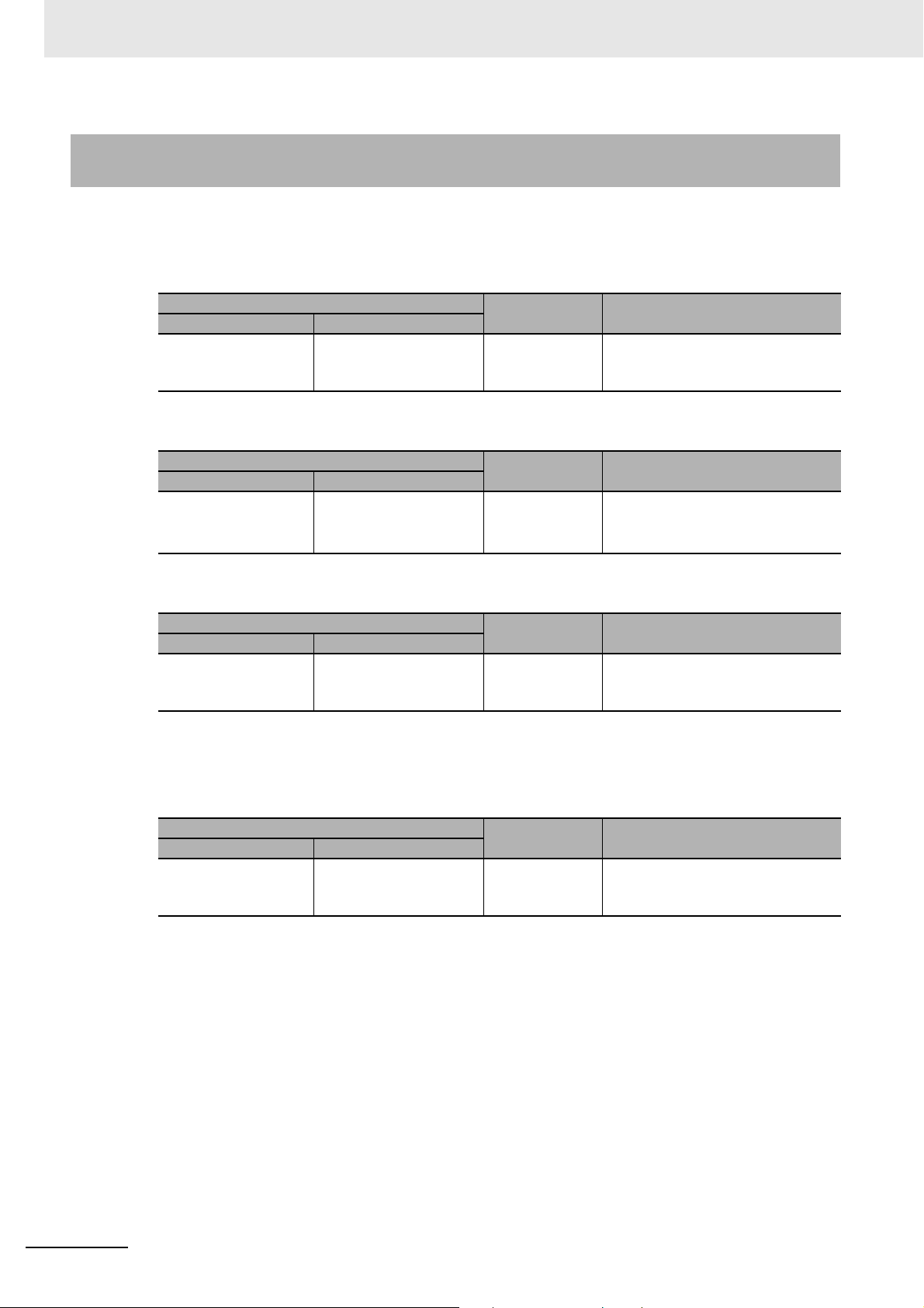
Appendices
A-3-3 Specific Values of NX Units Operate with Time Stamp Refresh-
ing
The following table gives specific values for each element of NX Units that operate with input refreshing
with input changed time for time stamp refreshing or output refreshing with specified time stamp.
z Input Data Processing Time of NX Unit (Tnx-InProc)
NX Units
Type Model
Digital Input Units Models support input
refreshing with input
changed time
Tnx-InProc Remarks
0 [μs] −
z Output Data Processing Time of NX Unit (Tnx-OutProc)
Type Model
Digital Output Units
NX Units
Models support output
refreshing with specified time stamp
Tnx-OutProc Remarks
0 [μs] −
z Input Delay Time of NX Unit (Tnx-Indelay)
NX Units
Type Model
Digital Input Units Models support input
refreshing with input
changed time
*1. If only a definition is given in the above table, refer to the data of the NX Units in Section 1 Data List or the
manuals for the specific NX Units for the values of the items.
Tnx-Indelay
ON/OFF
response time
*1
The ON/OFF response time
depends on the model of the Unit.
Remarks
z Output Delay Time of NX Unit (Tnx-Outdelay)
NX Units
Type Model
Digital Output Units Models support output
refreshing with specified
time stamp
*1. If only a definition is given in the above table, refer to the data of the NX Units in Section 1 Data List or the
manuals for the specific NX Units for the values of the items.
Tnx-Outdelay
ON/OFF
response time
*1
The ON/OFF response time
depends on the model of the Unit.
Remarks
A - 12
NX-series Data Reference Manual (W525)
Page 87
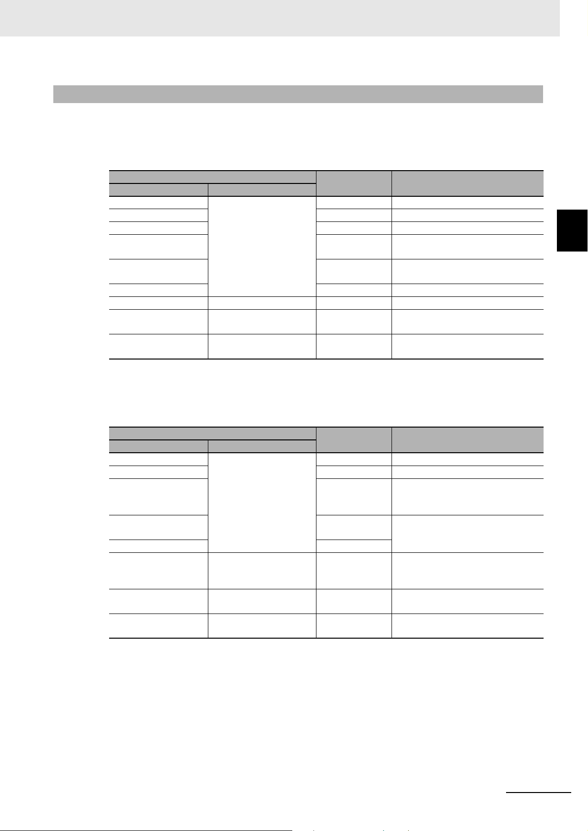
Appendices
A-3-4 Specific Values of NX Units Operate with Free-Run Refreshing
The following table gives specific values for each element of NX Units that operate with Free-Run
refreshing.
z Input Data Processing Time of NX Unit (Tnx-InProc)
A-3 Specific Values of NX Units for Perfor-
mance Calculation
NX Units
Type Model
Digital Input Units Models support Free-Run
Digital Mixed I/O Units 0 [μs] The value for digital inputs.
Analog Input Units 0 [μs] −
Temperature Input
Units
Incremental Encoder
Input Units
SSI Input Units 65 [μs] −
Load Cell Input Unit NX-RS1201 65 [µs] −
Heater Burnout Detection Units
Temperature Control
Units
*1. If only a definition is given in the above table, refer to the data of the NX Units in Section 1 Data List or the
manuals for the specific NX Units for the values of the items.
refreshing
NX-HB3101
/-HB3201
All models 50 [ms] This is the value for measured value
Tnx-InProc
0 [μs] −
Conversion time −
85 [μs] The value for pulse inputs and exter-
10 [ms] This is applicable to the CT inputs.
*1
nal inputs.
and CT input.
Remarks
z Output Data Processing Time of NX Unit (Tnx-OutProc)
NX Units
Type Model
Digital Output Units Models support Free-Run
Digital Mixed I/O Units 0 [μs] The value for digital outputs.
Analog Output Units Conversion time
Incremental Encoder
Input Units
SSI Input Units 40 [μs]
Load Cell Input Unit NX-RS1201 35 [µs] This is the value for operation com-
Heater Burnout Detection Units
Temperature Control
Units
*1. If only a definition is given in the above table, refer to the data of the NX Units in Section 1 Data List or the
manuals for the specific NX Units for the values of the items.
refreshing
NX-HB3101
/-HB3201
All models 50 [ms] This is applicable to the control out-
Tnx-OutProc
0 [μs] -
× Number of
points
40 [μs] This is the value for command val-
10 [ms] This is applicable to the control out-
*1
The conversion time and number of
points depend on the model of the
Unit.
ues and other output data process-
ing.
mands and other output data pro-
cessing.
puts.
puts.
Remarks
A
A-3-4 Specific Values of NX Units Operate with Free-Run Refreshing
NX-series Data Reference Manual (W525)
A - 13
Page 88

Appendices
z Input Delay Time of NX Unit (Tnx-Indelay)
NX Units
Type Model
Digital Input Units Models support Free-Run
refreshing
Digital Mixed I/O Units ON/OFF
Analog Input Units Conversion time
Temperature Input
Units
Incremental Encoder
Input Units
SSI Input Units 0 [μs] −
Load Cell Input Unit NX-RS1201 0 [µs] −
Heater Burnout Detection Units
Temperature Control
Units
*1. If only a definition is given in the above table, refer to the data of the NX Units in Section 1 Data List or the
manuals for the specific NX Units for the values of the items.
NX-HB3101
/-HB3201
All models 100 [ms] This is the value for measured value
Tnx-Indelay
ON/OFF
response time +
Input filter time
response time +
Input filter time
× Number of
points
Conversion time −
0 [μs] The value for pulse inputs and exter-
Control period This is applicable to the CT inputs.
*1
The ON/OFF response time
depends on the model of the Unit.
You can set the input filter time for
each Unit.
This is applicable to the digital
inputs.
The ON/OFF response time
depends on the model of the Unit.
You can set the input filter time for
each Unit.
The conversion time and number of
points depend on the model of the
Unit.
nal inputs.
The value set for Out Control
Period of the time-proportional output in the Unit operation settings of
the Heater Burnout Detection Unit.
and CT input.
Remarks
A - 14
NX-series Data Reference Manual (W525)
Page 89

z Output Delay Time of NX Unit (Tnx-Outdelay)
Appendices
A-3 Specific Values of NX Units for Perfor-
NX Units
Type Model
Digital Output Units Models support Free-Run
refreshing
Digital Mixed I/O Units ON/OFF
Analog Output Units 0 [μs] −
Heater Burnout Detec-
tion Units
Temperature Control
Units
*1. If only a definition is given in the above table, refer to the data of the NX Units in Section 1 Data List or the
manuals for the specific NX Units for the values of the items.
NX-HB3101
/-HB3201
Model number of voltage
output for driving SSR
Model number of linear
current output
Tnx-Outdelay
ON/OFF
response time
response time
Control period This is applicable to the control out-
Control period This is applicable to the control out-
0 [μs] −
*1
The ON/OFF response time
depends on the model of the Unit.
This is applicable to the digital out-
puts.
The ON/OFF response time
depends on the model of the Unit.
puts. The value set for Out Control
Period of the time-proportional out-
put in the Unit operation settings of
the Heater Burnout Detection Unit.
puts. The value set for Ch Control
Period (Heating) or Ch Control
Period (Cooling) in the Unit opera-
tion settings of the Temperature
Control Unit.
Remarks
mance Calculation
A
A-3-4 Specific Values of NX Units Operate with Free-Run Refreshing
NX-series Data Reference Manual (W525)
A - 15
Page 90

Appendices
NNX -T-TB
Product type
TB: Terminal block
Terminal specifications
A: Column letter indication A/B, without functional ground terminal
B: Column letter indication C/D, without functional ground terminal
C: Column letter indication A/B, with functional ground terminal
Number of terminals
08: 8 terminals
12: 12 terminals
16: 16 terminals
Other specifications
1: Terminal current capacity of 4 A
2: Terminal current capacity of 10 A
A-4 List of Screwless Clamping Terminal
Block Models
This section explains how to read the Screwless Clamping Terminal Block model numbers and shows
the Screwless Clamping Terminal Block models that are applicable to each Unit.
A-4-1 Model Notation
The Screwless Clamping Terminal Block models are assigned based on the following rules.
A-4-2 List of Terminal Block Models
The following table shows a list of Screwless Clamping Terminal Blocks.
Terminal Block model Number of terminals Ground terminal mark Terminal current capacity
NX-TBA081 8 Not provided 4 A
NX-TBA121 12
NX-TBA161 16
NX-TBB121 12
NX-TBB161 16
NX-TBA082 8 10 A
NX-TBA122 12
NX-TBA162 16
NX-TBB082 8
NX-TBB122 12
NX-TBB162 16
NX-TBC082 8 Provided
NX-TBC162 16
Note When you purchase a Terminal Block, purchase an NX-TB2.
A - 16
NX-series Data Reference Manual (W525)
Page 91
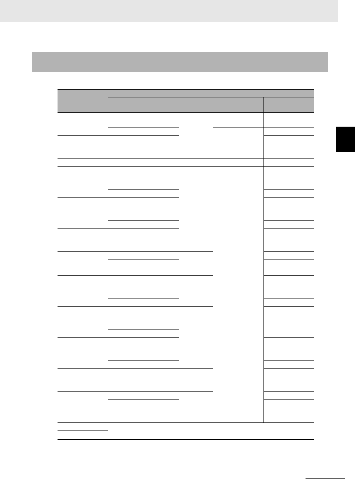
Appendices
A-4-3 Applicable Screwless Clamping Terminal Blocks for Each Unit
Model
The following indicates the Screwless Clamping Terminal Blocks that are applicable to each Unit.
A-4 List of Screwless Clamping Terminal
Unit model num-
ber
NX102- NX-TBC082 8 Provided 10 A
NX-ECC201 NX-TBA081 8 Not provided 4 A
NX-TBC082 Provided 10 A
NX-ECC202 NX-TBC082 10 A
NX-ECC203 NX-TBC082 10 A
NX-EIC202 NX-TBC082 8 Provided 10 A
NX-CSG320 NX-TBC082 8 Provided 10 A
NX-ID3 NX-TBA121 12 Not provided 4 A
NX-TBA122 10 A
NX-ID4 NX-TBA161 16 4 A
NX-TBA162 10 A
NX-ID5 NX-TBA161 4 A
NX-TBA162 10 A
NX-IA3117 NX-TBA081 8 4 A
NX-TBA082 10 A
NX-OD2 NX-TBA081 4 A
NX-TBA082 10 A
NX-OD3268 NX-TBA162 16 10 A
NX-OD3
(any model other
than NX-OD3268)
NX-OD4 NX-TBA161 16 4 A
NX-OD5 NX-TBA161 4 A
NX-OC2 NX-TBA081 8 4 A
NX-OC4633 NX-TBA082 10 A
NX-AD2 NX-TBA081 4 A
NX-AD3 NX-TBA121 12 4 A
NX-AD4 NX-TBA161 16 4 A
NX-HAD40 NX-TBA162/TBB162 16 10 A
NX-DA2 NX-TBA081 8 4 A
NX-DA3 NX-TBA121 12 4 A
NX-TS21 You cannot replace the Terminal Blocks.
NX-TS31
NX-TBA121 12 4 A
NX-TBA122 10 A
NX-TBA162 10 A
NX-TBA162 10 A
NX-TBA082 10 A
NX-TBB082
NX-TBA082 10 A
NX-TBA122 10 A
NX-TBA162 10 A
NX-TBA082 10 A
NX-TBA122 10 A
Refer to the NX-series Analog I/O Units User’s Manual (Cat. No. W522) for details.
Model
Terminal Block
Number of
terminals
Ground terminal
mark
Current capacity
Block Models
A
A-4-3 Applicable Screwless Clamping Terminal Blocks for Each Unit Model
NX-series Data Reference Manual (W525)
A - 17
Page 92

Appendices
Unit model num-
ber
NX-TS22 NX-TBA161 16 Not provided 4 A
NX-TBA162 10 A
NX-TS32 NX-TBA161/TBB161 4 A
NX-TBA162/TBB162 10 A
NX-HB301 NX-TBA161 4 A
NX-TBA162 10 A
NX-EC0112 NX-TBA161 4 A
NX-TBA162 10 A
NX-EC0122 NX-TBA161 16 Not provided 4 A
NX-TBA162 10 A
NX-EC0132 NX-TBA121/TBB121 12 Not provided 4 A
NX-TBA122/TBB122 10 A
NX-EC0142 NX-TBA121/TBB121 4 A
NX-TBA122/TBB122 10 A
NX-EC0212 NX-TBA121 4 A
NX-TBA122 10 A
NX-EC0222 NX-TBA121 4 A
NX-TBA122 10 A
NX-ECS112 NX-TBA121 4 A
NX-TBA122 10 A
NX-ECS212 NX-TBA121 4 A
NX-TBA122 10 A
NX-PG0112 NX-TBA161 16 4 A
NX-TBA162 10 A
NX-PG0122 NX-TBA161 4 A
NX-TBA162 10 A
NX-CIF101 NX-TBC162 Provided 10 A
NX-CIF105 NX-TBC162 10 A
NX-RS1201 NX-TBC162 10 A
NX-ILM400 NX-TBA162 Not provided 10 A
NX-TC4 The terminal block can not be replaced.
Refer to the NX-series Temperature Control Units User's Manual (Cat. No. H228) for
details.
NX-PD1000 NX-TBA081 8 Not provided 4 A
NX-TBC082 Provided 10 A
NX-PF0630 NX-TBA081 Not provided 4 A
NX-TBA082 10 A
NX-PF0730 NX-TBA082 10 A
NX-PC NX-TBA161 16 4 A
NX-TBA162 10 A
NX-TBX01 NX-TBA161 4 A
NX-TBC162 Provided 10 A
NX-SL3300 No Terminal Blocks
NX-SL3500 No Terminal Blocks
NX-SL5500 No Terminal Blocks
NX-SL5700 No Terminal Blocks
Model
Terminal Block
Number of
terminals
Ground terminal
mark
Current capacity
A - 18
NX-series Data Reference Manual (W525)
Page 93

Appendices
Precautions for Correct Use
A-4 List of Screwless Clamping Terminal
Unit model num-
ber
NX-SIH400 NX-TBA081 8 Not provided 4 A
NX-TBA082 10 A
NX-SID800 NX-TBA161 16 4 A
NX-TBA162 10 A
NX-SOD400 NX-TBA081 8 4 A
NX-TBA082 10 A
NX-SOH200 NX-TBA081 4 A
NX-TBA082 10 A
Model
Terminal Block
Number of
terminals
Ground terminal
mark
Current capacity
You can mount NX-TB1 and NX-TB2 Terminal Blocks to the Units whose terminal
current capacity is specified to 4 A or less.
However, even if you mount the NX-TB2 Terminal Block, the current specification does
not change because the current capacity specification of the terminals on the Units is 4 A or
less.
Block Models
A
A-4-3 Applicable Screwless Clamping Terminal Blocks for Each Unit Model
NX-series Data Reference Manual (W525)
A - 19
Page 94

Appendices
A-5 Version Information with CPU Units
This section provides version-related information when connecting Units to a CPU Unit.
This section describes the relationship between the unit versions of each Unit and the CPU Unit, and
Sysmac Studio version, and the specification changes for each unit version of each Unit.
A-5-1 Relationship between Unit Versions of Units
The relationship between the unit versions of each Unit and the CPU Unit, and Sysmac Studio version
are shown below.
Interpreting the Version Combination Tables
The items that are used in the version combination tables are given below.
Refer to the user's manual for the CPU Unit for the models of CPU Unit to which NX Units can be
connected.
NX Units Corresponding unit versions/versions
Model Unit version CPU Units Sysmac Studio
Model numbers of the NX
Units.
Unit versions of the NX
Units.
Unit versions of the CPU
Unit that are compatible
with the NX Units.
Sysmac Studio versions
that are compatible with
the NX Units and CPU
Units.
Version Combination Tables
• With the combinations of the unit versions/versions shown below, you can use the functions that are
supported by the unit version of the Unit model. Use the unit versions/versions that correspond to the
NX Unit models and the unit versions or the later/higher versions. You cannot use the specifications
that were added or changed for the relevant NX Unit models and the unit versions unless you use the
corresponding unit versions/versions.
• You cannot connect the relevant NX Unit to the CPU Unit if “---” is shown in the corresponding unit
versions/versions column.
• Depending on the type and model of the Unit to which the NX Unit is connected, some Units do not
have the corresponding versions given in the table. If a Unit does not have the specified version, support is provided by the oldest available version after the specified version. Refer to the user’s manuals for the specific Units for the relation between models and versions.
• If you use the corresponding unit versions/versions given in the following table or later/higher versions, refer to the version information on the CPU Unit.
A - 20
NX-series Data Reference Manual (W525)
Page 95

z Digital I/O Units
NX Units Corresponding unit versions/versions
Model Unit version CPU Units Sysmac Studio
NX-ID3317 Ver.1.0 Ver.1.13 Ver.1.17
NX-ID3343
NX-ID3344
NX-ID3417
NX-ID3443
NX-ID3444
NX-ID4342
NX-ID4442
NX-ID5142-1
NX-ID5142-5
NX-ID5342
NX-ID5442
NX-ID6142-5
NX-ID6142-6
NX-IA3117
NX-OD2154
NX-OD2258
NX-OD3121
NX-OD3153
NX-OD3256
NX-OD3257
NX-OD3268
NX-OD4121
NX-OD4256
NX-OD5121
NX-OD5121-1
NX-OD5121-5
NX-OD5256
NX-OD5256-1
NX-OD5256-5
NX-OD6121-5
NX-OD6121-6
NX-OD6256-5
NX-OC2633
NX-OC2733
NX-OC4633
NX-MD6121-5
NX-MD6121-6
NX-MD6256-5
Appendices
A-5 Version Information with CPU Units
A
A-5-1 Relationship between Unit Versions of Units
NX-series Data Reference Manual (W525)
A - 21
Page 96
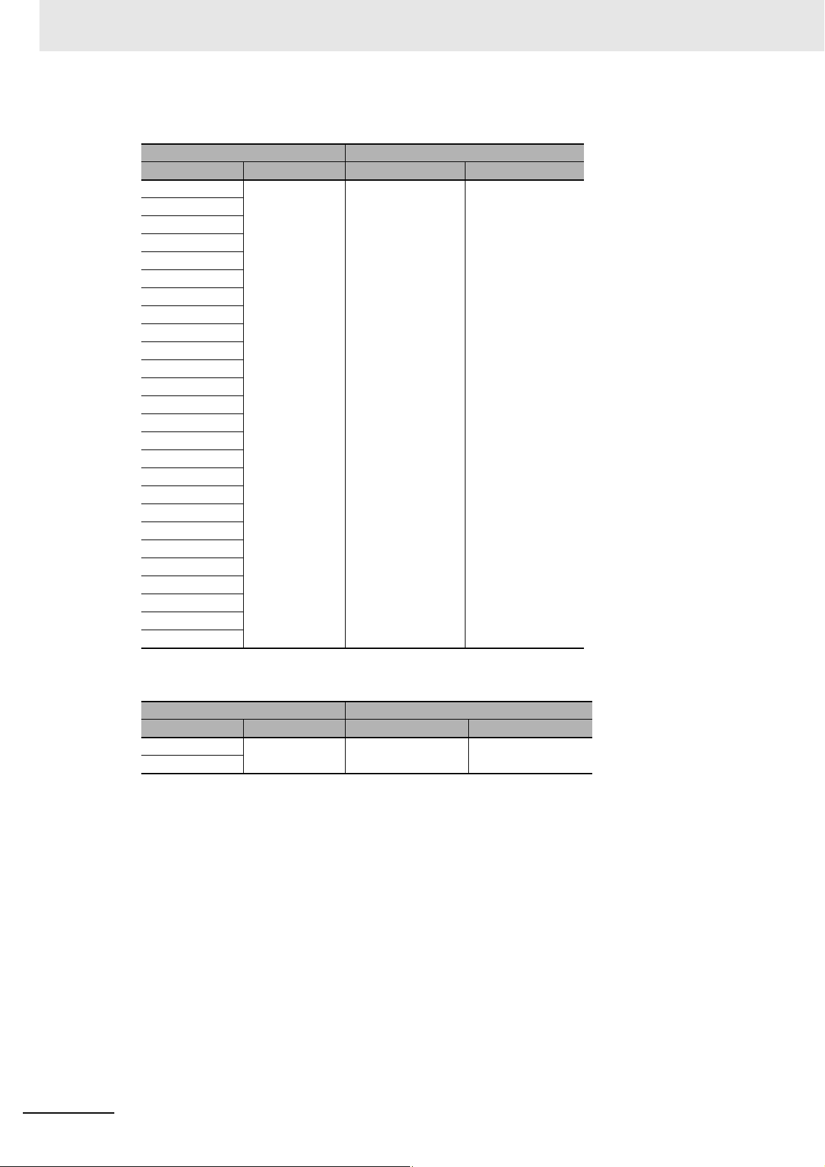
Appendices
z Analog Input Units/Analog Output Units
NX-AD2203 Ver.1.0 Ver.1.13 Ver.1.17
NX-AD2204
NX-AD2208
NX-AD2603
NX-AD2604
NX-AD2608
NX-AD3203
NX-AD3204
NX-AD3208
NX-AD3603
NX-AD3604
NX-AD3608
NX-AD4203
NX-AD4204
NX-AD4208
NX-AD4603
NX-AD4604
NX-AD4608
NX-DA2203
NX-DA2205
NX-DA2603
NX-DA2605
NX-DA3203
NX-DA3205
NX-DA3603
NX-DA3605
NX Units Corresponding unit versions/versions
Model Unit version CPU Units Sysmac Studio
z High-speed Analog Input Units
NX Units Corresponding unit versions/versions
Model Unit version CPU Units Sysmac Studio
NX-HAD401 Ver.1.0 Ver.1.18 Ver.1.23
NX-HAD402
A - 22
NX-series Data Reference Manual (W525)
Page 97
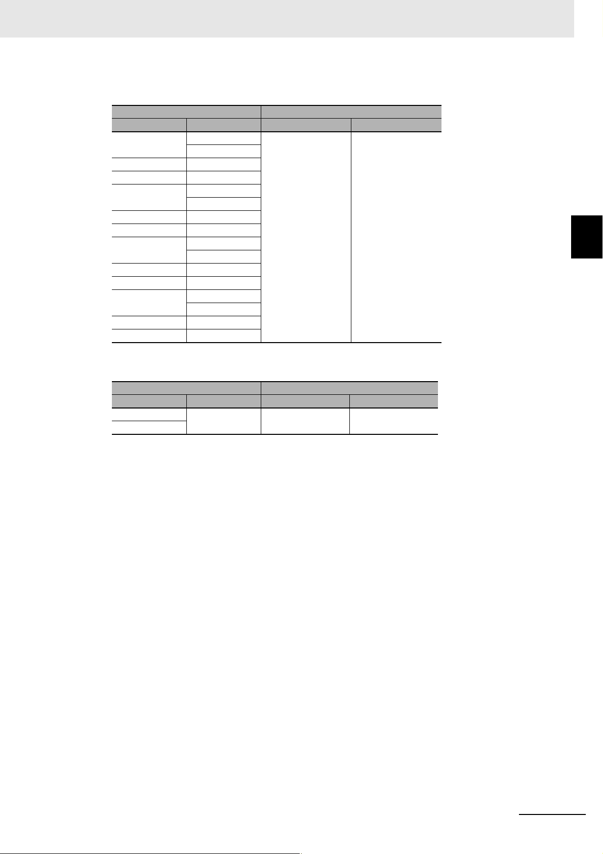
z Temperature Input Units
NX Units Corresponding unit versions/versions
Model Unit version CPU Units Sysmac Studio
NX-TS2101 Ver.1.0 Ver.1.13 Ver.1.17
Ver.1.1
NX-TS2102 Ver.1.1
NX-TS2104 Ver.1.1
NX-TS2201 Ver.1.0
Ver.1.1
NX-TS2202 Ver.1.1
NX-TS2204 Ver.1.1
NX-TS3101 Ver.1.0
Ver.1.1
NX-TS3102 Ver.1.1
NX-TS3104 Ver.1.1
NX-TS3201 Ver.1.0
Ver.1.1
NX-TS3202 Ver.1.1
NX-TS3204 Ver.1.1
Appendices
A-5 Version Information with CPU Units
A
A-5-1 Relationship between Unit Versions of Units
z Heater Burnout Detection Units
NX Units Corresponding unit versions/versions
Model Unit version CPU Units Sysmac Studio
NX-HB3101 Ver.1.0 Ver.1.13 Ver.1.17
NX-HB3201
NX-series Data Reference Manual (W525)
A - 23
Page 98
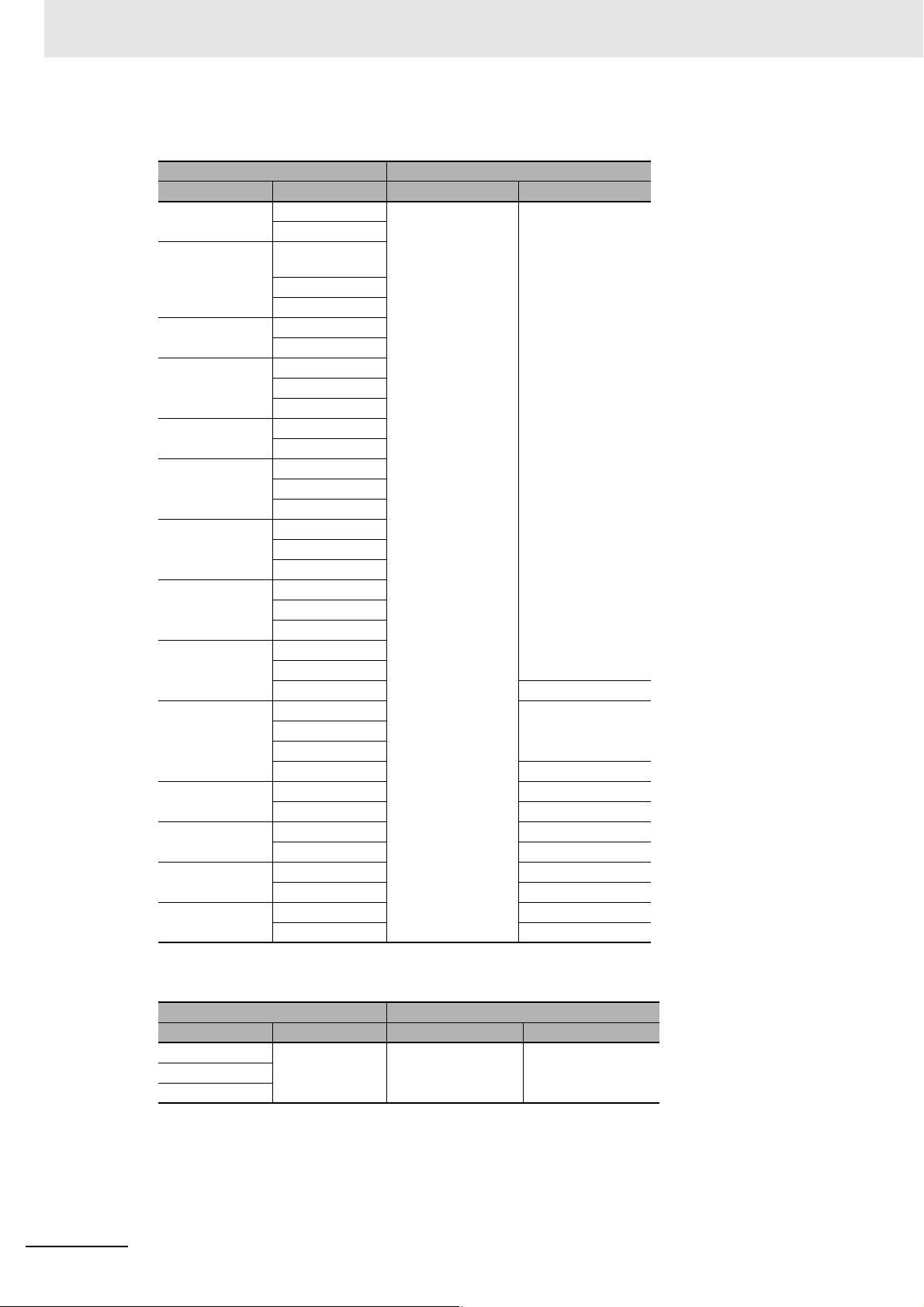
Appendices
z Position Interface Units
NX-EC0112 Ver.1.1 Ver.1.13 Ver.1.17
NX-EC0122 Ver.1.0
NX-EC0132 Ver.1.1
NX-EC0142 Ver.1.0
NX-EC0212 Ver.1.1
NX-EC0222 Ver.1.0
NX-ECS112 Ver.1.0
NX-ECS212 Ver.1.0
NX-PG0112 Ver.1.1
NX-PG0122 Ver.1.0 Ver.1.17
NX-PG0232-5 Ver.1.2 Ver.1.17
NX-PG0242-5 Ver.1.2 Ver.1.17
NX-PG0332-5 Ver.1.2 Ver.1.17
NX-PG0342-5 Ver.1.2 Ver.1.17
NX Units Corresponding unit versions/versions
Model Unit version CPU Units Sysmac Studio
Ver. 1.2
Ver. 1.1
Ver. 1.2
Ver. 1.2
Ver. 1.1
Ver. 1.2
Ver. 1.2
Ver. 1.1
Ver. 1.2
Ver. 1.1
Ver. 1.2
Ver. 1.1
Ver. 1.2
Ver. 1.2
Ver.1.3 Ver.1.19
Ver. 1.1
Ver. 1.2
Ver.1.3 Ver.1.19
Ver.1.3 Ver.1.19
Ver.1.3 Ver.1.19
Ver.1.3 Ver.1.19
Ver.1.3 Ver.1.19
A - 24
z Communications Interface Units
NX Units Corresponding unit versions/versions
Model Unit version CPU Units Sysmac Studio
NX-CIF101 Ver.1.0 Ver.1.13 Ver.1.17
NX-CIF105
NX-CIF210
NX-series Data Reference Manual (W525)
Page 99
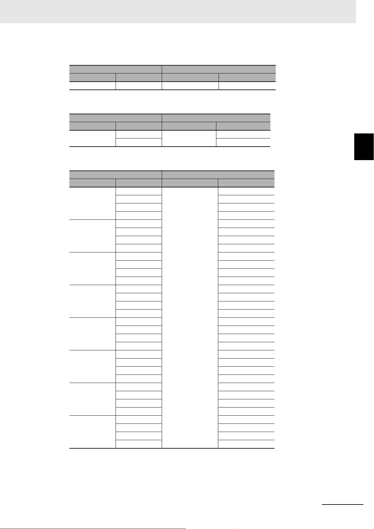
Load Cell Input Unit
NX Units Corresponding unit versions/versions
Model Unit version CPU Units Sysmac Studio
NX-RS1201 Ver.1.0 Ver.1.13 Ver.1.17
IO-Link Master Unit
NX Units Corresponding unit versions/versions
Model Unit version CPU Units Sysmac Studio
NX-ILM400 Ver.1.0 Ver.1.13 Ver.1.17
Ver.1.1 Ver.1.20
Appendices
A-5 Version Information with CPU Units
A
Temperature Control Units
NX Units Corresponding unit versions/versions
Model Unit version CPU Units Sysmac Studio
NX-TC2405 Ver.1.0 Ver.1.13 Ver.1.21
Ver.1.1 Ver.1.22
Ver.1.2 Ver.1.30
Ver.1.3 Ver.1.40
NX-TC2406 Ver.1.0 Ver.1.21
Ver.1.1 Ver.1.22
Ver.1.2 Ver.1.30
Ver.1.3 Ver.1.40
NX-TC2407 Ver.1.0 Ver.1.21
Ver.1.1 Ver.1.22
Ver.1.2 Ver.1.30
Ver.1.3 Ver.1.40
NX-TC2408 Ver.1.0 Ver.1.21
Ver.1.1 Ver.1.22
Ver.1.2 Ver.1.30
Ver.1.3 Ver.1.40
NX-TC3405 Ver.1.0 Ver.1.21
Ver.1.1 Ver.1.22
Ver.1.2 Ver.1.30
Ver.1.3 Ver.1.40
NX-TC3406 Ver.1.0 Ver.1.21
Ver.1.1 Ver.1.22
Ver.1.2 Ver.1.30
Ver.1.3 Ver.1.40
NX-TC3407 Ver.1.0 Ver.1.21
Ver.1.1 Ver.1.22
Ver.1.2 Ver.1.30
Ver.1.3 Ver.1.40
NX-TC3408 Ver.1.0 Ver.1.21
Ver.1.1 Ver.1.22
Ver.1.2 Ver.1.30
Ver.1.3 Ver.1.40
A-5-1 Relationship between Unit Versions of Units
NX-series Data Reference Manual (W525)
A - 25
Page 100
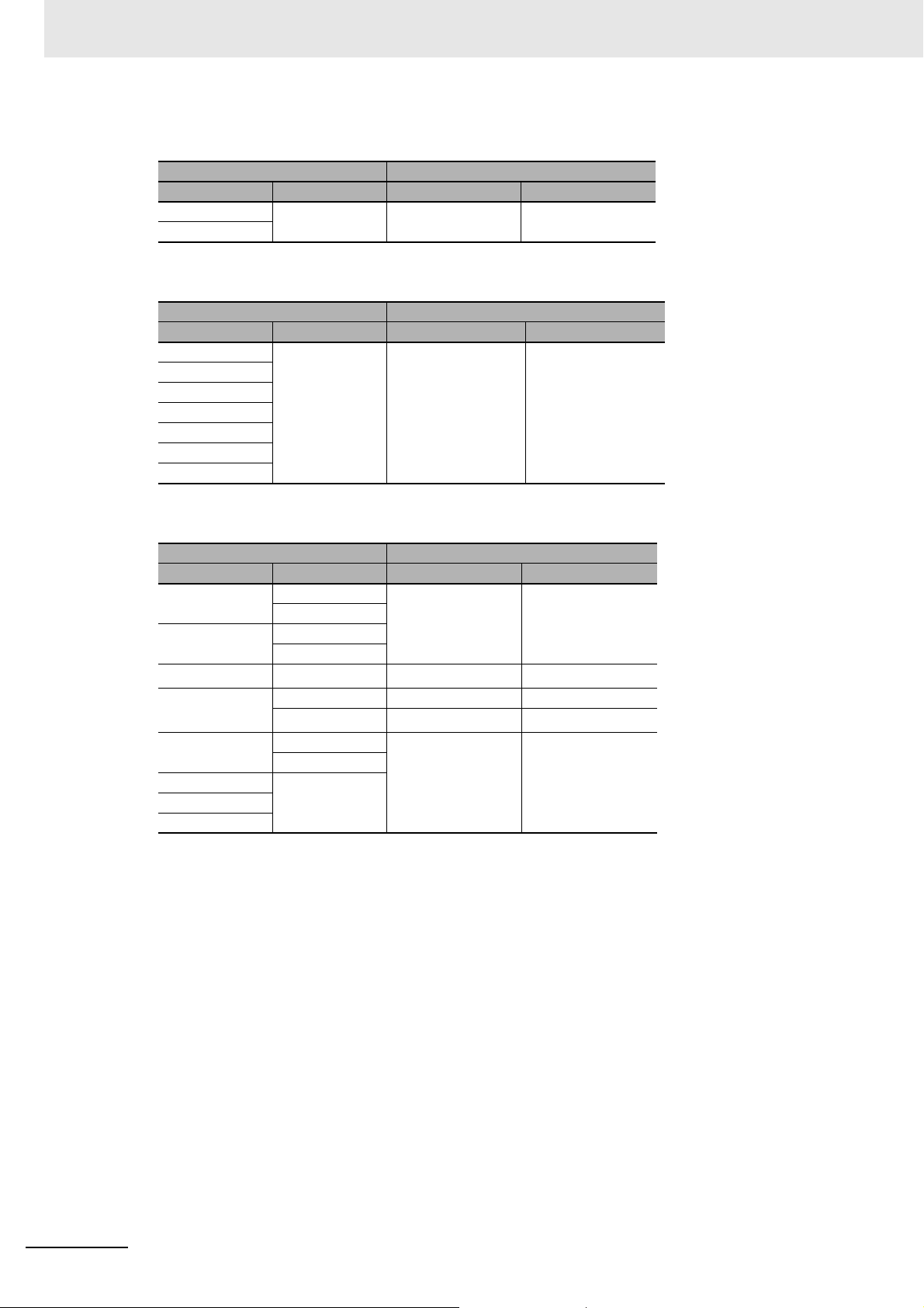
Appendices
z RFID Units
NX-V680C1 Ver.1.0 Ver.1.13 Ver.1.25
NX-V680C2
z System Units
NX-PD1000 Ver.1.0 Ver.1.13 Ver.1.17
NX-PF0630
NX-PF0730
NX-PC0020
NX-PC0010
NX-PC0030
NX-TBX01
NX Units Corresponding unit versions/versions
Model Unit version CPU Units Sysmac Studio
NX Units Corresponding unit versions/versions
Model Unit version CPU Units Sysmac Studio
z Safety Control Units
NX Units Corresponding unit versions/versions
Model Unit version CPU Units Sysmac Studio
NX-SL3300 Ver.1.0
Ver. 1.1
NX-SL3500 Ver.1.0
Ver. 1.1
*2
NX-SL5500
NX-SL5700
NX-SIH400 Ver.1.0
NX-SID800 Ver.1.0
NX-SOD400
NX-SOH200
*1. You cannot connect NX Units to an NX1P2 CPU Unit.
*2. For the NX-SL5500, there is no unit version of 1.2 or earlier.
*3. For the NX-SL5700, there is no unit version of 1.1 or earlier.
Ver. 1.3
*3
Ver.1.2 --- ---
Ver. 1.3
Ver. 1.1
Ver.1.30
Ver.1.31
Ver.1.31
Ver.1.30
*1
*1
*1
*1
Ver.1.23
Ver.1.24
Ver.1.24
Ver.1.23
A - 26
NX-series Data Reference Manual (W525)
 Loading...