

Page 1

Cat. No. V103-E1-06
NV Series
NV3W(-V1)
NV4W
NV3Q
Programmable Terminals
SETUP MANUAL
Page 2

NOTE
All rights reserved. No part of this publication may be reproduced, stored in a retrieval system, or transmitted, in
any form, or by any means, mechanical, electronic, photocopying, recording, or otherwise, without the prior written
permission of OMRON.
No patent liability is assumed with respect to the use of the information contained herein. Moreover, because
OMRON is constantly striving to improve its high-quality products, the information contained in this manual is
subject to change without notice. Every precaution has been taken in the preparation of this manual. Nevertheless,
OMRON assumes no responsibility for errors or omissions. Neither is any liability assumed for damages resulting
from the use of the information contained in this publication.
Trademarks
• Microsoft, Windows, Windows Vista, Excel, and Visual Basic are either registered trademarks or trademarks of
Microsoft Corporation in the United States and other countries.
Other company names and product names in this document are the trademarks or registered trademarks of their
respective companies.
Copyrights
Microsoft product screen shots reprinted with permission from Microsoft Corporation.
Page 3

NV Series
NV3W(-V1)
NV4W
NV3Q
Programmable Terminals
Revised May 2015
Page 4

iv
Page 5

Notice
Precautions
for Sa fe Use
Precautions
for Correct Use
OMRON products are manufactured for use according to proper procedures by a qualified operator
and only for the purposes described in this manual.
The following conventions are used to indicate and classify precautions in this manual. Always heed
the information provided with them. Failure to heed precautions can result in injury to people or damage to property.
!DANGER Indicates an imminently hazardous situation which, if not avoided, will result in death or
serious injury . Additionally, there may be severe property damage.
!WARNING Indicates a potentially hazardous situation which, if not avoided, could result in death or
serious injury . Additionally, there may be severe property damage.
!Caution Indicates a potentially hazardous situation which, if not avoided, may result in minor or
moderate injury, or property damage.
OMRON Product References
All OMRON products are capitalized in this man ual. The w ord “Unit” is also capitalized when it refers to
an OMRON product, regardless of whether or not it appears in the proper name of the product.
The abbreviation “Ch,” which appears in some displays and on some OMRON products, often means
“word” and is abbreviated “Wd” in documentation in this sense.
The abbreviation “PLC” means Programmable Controller.
The abbreviation “host” means a controller, such as an IBM PC/AT or compatible computer, that con-
trols a PT (Programmable Terminal).
Visual Aids
The following headings appear in the left column of the manual to help you locate different types of
information.
CS1G-CPU@@-V1 Boxes in model numbers indicate v ariable characters. For example, “CS1G-CPU@@-
Indicates precautions on handling the product to ensure that the product is used safely.
Indicates precautions to ensure that product functions and performances are realized, to
ensure that the reliability of the product is maintained, and to ensure that the product is
otherwise used correctly.
Note Indicates information of particular interest for efficient and convenient opera-
tion of the product.
Reference Indicates supplementary information on procedures, descriptions, and settings.
1,2,3... 1. Indicates lists of one sort or another , such as procedures, checklists, etc.
EV1” indicates the following models: CS1G-CPU42-EV1, CS1G-CPU43-EV1, CS1GCPU44-EV1, and CS1G-CPU45-EV1.
v
Page 6

vi
Page 7

TABLE OF CONTENTS
SECTION 1
Overview . . . . . . . . . . . . . . . . . . . . . . . . . . . . . . . . . . . . . . . . . 1
1-1 Features of NV-series PTs . . . . . . . . . . . . . . . . . . . . . . . . . . . . . . . . . . . . . . . . . . . . . . . . . . .2
1-2 System Configuration . . . . . . . . . . . . . . . . . . . . . . . . . . . . . . . . . . . . . . . . . . . . . . . . . . . . . . 5
1-3 Models . . . . . . . . . . . . . . . . . . . . . . . . . . . . . . . . . . . . . . . . . . . . . . . . . . . . . . . . . . . . . . . . . . 9
1-4 Specifications. . . . . . . . . . . . . . . . . . . . . . . . . . . . . . . . . . . . . . . . . . . . . . . . . . . . . . . . . . . . . 12
1-5 Functions . . . . . . . . . . . . . . . . . . . . . . . . . . . . . . . . . . . . . . . . . . . . . . . . . . . . . . . . . . . . . . . . 29
1-6 System Versions. . . . . . . . . . . . . . . . . . . . . . . . . . . . . . . . . . . . . . . . . . . . . . . . . . . . . . . . . . . 30
SECTION 2
Part Names, Functions, and Internal Configuration. . . . . . 33
2-1 Part Names and Functions. . . . . . . . . . . . . . . . . . . . . . . . . . . . . . . . . . . . . . . . . . . . . . . . . . .34
2-2 Internal Operation . . . . . . . . . . . . . . . . . . . . . . . . . . . . . . . . . . . . . . . . . . . . . . . . . . . . . . . . . 39
SECTION 3
Preparations for Operation . . . . . . . . . . . . . . . . . . . . . . . . . . 41
3-1 Preparations for Operation. . . . . . . . . . . . . . . . . . . . . . . . . . . . . . . . . . . . . . . . . . . . . . . . . . . 42
SECTION 4
Installing and Wiring the PT. . . . . . . . . . . . . . . . . . . . . . . . . 45
4-1 Installing the PT. . . . . . . . . . . . . . . . . . . . . . . . . . . . . . . . . . . . . . . . . . . . . . . . . . . . . . . . . . . 46
4-2 Connection Diagrams . . . . . . . . . . . . . . . . . . . . . . . . . . . . . . . . . . . . . . . . . . . . . . . . . . . . . . 59
4-3 Communications/Power Connector Pin Assignments. . . . . . . . . . . . . . . . . . . . . . . . . . . . . . 63
4-4 Wiring the Power Supply and Serial Communications. . . . . . . . . . . . . . . . . . . . . . . . . . . . . 67
4-5 Precautions When Grounding (24-V Models Only) . . . . . . . . . . . . . . . . . . . . . . . . . . . . . . . 76
4-6 Starting an NV-series PT . . . . . . . . . . . . . . . . . . . . . . . . . . . . . . . . . . . . . . . . . . . . . . . . . . . . 77
SECTION 5
System Menu . . . . . . . . . . . . . . . . . . . . . . . . . . . . . . . . . . . . . . 79
5-1 Configuration Settings from the System Menu . . . . . . . . . . . . . . . . . . . . . . . . . . . . . . . . . . . 80
5-2 Self-diagnosis from the System Menu. . . . . . . . . . . . . . . . . . . . . . . . . . . . . . . . . . . . . . . . . . 94
SECTION 6
Connecting and Setting PLCs or Temperature Controllers 97
6-1 Connecting and Setting an OMRON PLC. . . . . . . . . . . . . . . . . . . . . . . . . . . . . . . . . . . . . . . 98
6-2 PT Settings. . . . . . . . . . . . . . . . . . . . . . . . . . . . . . . . . . . . . . . . . . . . . . . . . . . . . . . . . . . . . . . 101
6-3 PLC Settings . . . . . . . . . . . . . . . . . . . . . . . . . . . . . . . . . . . . . . . . . . . . . . . . . . . . . . . . . . . . . 103
6-4 SPMA (Single Port Multiple Access) . . . . . . . . . . . . . . . . . . . . . . . . . . . . . . . . . . . . . . . . . . 1 07
6-5 Connecting to EJ1 Temperature Controllers Using Modbus-RTU . . . . . . . . . . . . . . . . . . . . 110
vii
Page 8

TABLE OF CONTENTS
SECTION 7
Maintenance and Troubleshooting . . . . . . . . . . . . . . . . . . . . 113
7-1 Maintenance. . . . . . . . . . . . . . . . . . . . . . . . . . . . . . . . . . . . . . . . . . . . . . . . . . . . . . . . . . . . . . 1 14
7-2 Inspection and Cleaning . . . . . . . . . . . . . . . . . . . . . . . . . . . . . . . . . . . . . . . . . . . . . . . . . . . . 116
7-3 Troubleshooting the NV3W. . . . . . . . . . . . . . . . . . . . . . . . . . . . . . . . . . . . . . . . . . . . . . . . . . 117
7-4 Troubleshooting the NV3W-V1, NV4W or NV3Q. . . . . . . . . . . . . . . . . . . . . . . . . . . . . . . . 120
7-5 Error Codes and Countermeasures . . . . . . . . . . . . . . . . . . . . . . . . . . . . . . . . . . . . . . . . . . . . 123
Index. . . . . . . . . . . . . . . . . . . . . . . . . . . . . . . . . . . . . . . . . . . . . 131
Revision History . . . . . . . . . . . . . . . . . . . . . . . . . . . . . . . . . . . 133
viii
Page 9

About this Manual
This manual describes installing and setting up the NV -series PTs and includes the sections described
below .
Please read this manual carefully and be sure you understand the information provided before
attempting to install or operate an NV -series PT. Be sure to read the precautions provided in the following section.
Precautions
This section provides general precautions for using the NV-series PTs and related devices.
Section 1 Overview
This section introduces the NV-series PTs, including the system configuration, a vailable models, and
specifications.
Section 2 Part Names, Functions, and Internal Configuration
This section describes the functions of the various parts of an NV-series PT and how the NV-series
PTs operate internally.
Section 3 Preparations for Operation
This section outlines the steps required to prepare an NV-series PT for operation.
Section 4 Installing and Wiring the PT
This section describes how to install and wire an NV-series PT and start the PT for the first time.
Section 5 System Menu
This section describes the operations and settings that can be performed on the System Menu of an
NV-series PT.
Section 6 Connecting and Setting PLCs or Temperature Controllers
This section provides inf ormation and procedures required to connect an NV-series PT to an OMR ON
PLC.
Section 7 Maintenance and Troubleshooting
This section describes the maintenance and inspections required for NV-series PTs and provides
troubleshooting information for when problems occur with NV-series PTs.
ix
Page 10

x
Page 11

Related Manuals
This
Manual
The following manuals are used for NV-series PTs. (The boxes at the end of the catalog
numbers indicate the revision code.)
NV-series PT Setup Manual..................................... V103-E1-@
This manual describes how to connect an NV-series PT to an OMRON PLC, features and
specifications, methods to set up communications and operation, and procedures for
maintenance and troubleshooting.
Refer to the NV-series PT Programming Manual (V104-E1-@) for more information on PT
functions and specific operating procedures.
NV-series PT Programming Manual......................... V104-E1-@
This manual describes the software functionality of NV-series PTs, how to install the NVDesigner, and the features of the NV-Designer.
For more information on NV-Designer operating procedures, refer to the online help in the
NV-Designer.
NV-series PT Host Connection Manual.................... V105-E1-@
This manual describes how to connect an NV-series PT to a PLC produced by a man u facturer other than OMRON, including PLC memor y ar ea designat ions, communications settings, and connection method s.
xi
Page 12

Terminology
The following terminology is used in this manual.
PT In this manual, indicates an NV-series Programmable Terminal.
NV Series Indicates products in the OMRON NV Series of Programmable Terminals.
PLC Indicates a Programmable Controller in the OMRON SYSMAC CS/CJ/CP,
C, or CVM1/CV Series of Programmable Controllers.
CPU Unit Indicates a CPU Unit in the OMRON SYSMAC CS/CJ/CP, C, or CVM1/CV
Series of Programmable Controllers.
NV-Designer Indicates the OMRON NV -Designer.
Host Indicates the PLC, IBM PC/AT or compatible computer, or personal com-
puter functioning as the control device and interfaced with the NV-series PT.
xii
Page 13

Introduction
● Intended Audience
This manual is intended for the following personnel, who must also have knowledge of
electrical systems (an electrical engineer or the equivalent).
• Personnel in charge of introducing FA systems into production facilities.
• Personnel in charge of designing FA systems.
• Personnel in charge of installing and connecting FA systems.
• Personnel in charge of managing FA systems and facilities.
● General Precautions
• T he user must operate the product according to the performance specifications
described in the operation manuals.
• Do not use the PT touch switch input functions for applications where danger to
human life or serious property damage is possible, or for emergency switch applications.
• Before using the product under conditions which are not described in the manual or
applying the product to nuclear control systems, railroad systems, aviation systems,
vehicles, combustion systems, medical equipment, amusement machines, safety
equipment, and other systems, machines and equipment that may have a serious
influence on lives and property if used improperly, consult your OMRON representative.
• Make sure that the ratings and performance characteristics of the product are sufficient for the systems, machines, and equipment, and be sure to provide the systems,
machines, and equipment with double safety mechanisms.
• This manual provides information for connecting and setting up an NV-series PT. Be
sure to read this manual before attempting to use the PT and keep this manual close
at hand for reference during installation and operation.
xiii
Page 14
Safety Precautions
Notation Used for Safety Information
The following notation is used in this manual to provide precautions required to ensure
safe usage of the product.
The safety precautions that are provided are extremely important to safety.
Always read and heed the information provided in all safety precautions.
The following notation is used.
Definition of Precautionary Information
!WARNING
Symbols
Indicates a potentially hazardous situation which, if not avoided, will
result in minor or moderate injury, or may result in serious injury or
death. Additionally there may be significant property damage.
Prohibition
Indicates a general prohibition.
Caution
Indicates general cautionary, warning, or danger level information.
!WARNING
Always ensure that the personnel in charge confirm that installation,
inspection, and maintenance were properly performed for the PT. “Personnel in charge” refers to individuals qualified and responsible for
ensuring safety during machine design, installation, operation, maintenance, and disposal.
Ensure that installation and post-installation checks are performed by
personnel in charge who possess a thorough understanding of the
machinery to be installed.
Do not use the input functions of the PT, such as the function switches
or switches on the touch panel, in applications that involve human life,
in applications that may result in serious injury, or for emergency stop
switches.
Do not attempt to disassemble, repair, or modify the PT. Doing so may
impair the safety functions.
Do not attempt to take the Unit apart and do not touch any internal
parts while the power is being supplied. Doing either of these may
result in electrical shock.
The PT uses an analog touch panel. Never press more than two points
on the panel at a time. Otherwise, it may activate a switch somewhere
between the two points.
xiv
Page 15
Precautions for Safe Use
1. When unpacking the Units, chec k carefully for any external scratches or other damage.
Also, shake the Units gently and check for any abnormal sound.
2. The PT must be installed in a control panel.
3. The mounting panel must be between 1.6 and 4.8 mm thick. Tighten the Mounting
Bracket s evenly to a torque of b etw een 0 .1 and 0 .25 N· m for the NV3W/NV3Q and between 0.2 and 0.3 N·m f or the NV3W- V1/NV4W to maintain water and dust resistance.
Make sure the panel is not dirty or warped and that it is strong enough to hold the Units .
4. Do not let metal particles enter the Units when preparing the panel.
5. Do not connect an AC power supply to the DC power terminals.
6. Do not perform a dielectric voltage test.
7. Use a DC power supply that will provide a stable output ev en if the input is momentarily
interrupted for 10 ms, and which has reinforced or double insulation.
Model Rated power supply voltage Capacity
NV3W-M@20L
NV3W-M@20L-V1
NV4W-M@21
NV4W-M@41
NV3W-M@20
NV3W-M@40
NV3W-M@20-V1
NV3W-M@40-V1
NV3Q-MR@@ 2.4 W min.
NV3Q-SW@@ 3.6 W min.
8. Use a twisted-pair cable to connect to the po wer terminals. Tighten the terminal screws
to a torque of between 0.22 and 0.30 N·m. Make sure the screws are properly tightened.
9. To prevent malfunctions caused by noise, ground the PT correctly.
10. Do not touch the surfa ce of the circuit boards or the componen ts mounted on them with
your bare hands. Discharge any static electricity from your body before handling the
boards.
11. Turn OFF the power supply before connecting or disconnecting cables.
12. The maximum tensile load for cables is 30 N. Do not apply loads greater than this.
13. Confirm the safety of the system before turning ON or OFF the power supply.
14. Cycle the power supply after changing the DIP switch settings.
15. Do not perform the following operations while the SD memory card is being accessed
(NV4W and NV3Q only):
• Turning OFF the power supply to the PT
• Removing the memory card
Always follow the specified procedure when removing the memory card.
16. Start actual system application only after sufficiently checking screen data and t he operation of the program in the PLC (host).
17. Do not press the touch switch with a force greater than 30 N.
18. Do not use a screwdriver or any ot her tool to press a touch switch.
19. Confirm the safety of the system before pressing any touch switch.
20. Do not accidentally press touch switches whe n the backlight is not lit or when the display does not appear . Conf irm the safety of the system bef ore pressing touch s witches .
5 VDC (allowable range: 4.5 to 5.5 VDC) 1 W min.
24 VDC (allowable range: 21.6 to 26.4 VDC) 1.7 W min.
2 W min.
1.9 W min.
xv
Page 16

21. Before initializing screen data, co nfirm that existing data is back ed up at the NV -Designer.
22. When changing the password with the system menu, do not reset or turn OFF the pow-
er supply until writing is finished.
23. Before using the SPM A function to change memory values in the PLC or tr ansfer ladder
programming, confirm that the PT is oper ating. The SPMA fu nction cannot be used unless the PT is operating.
24. Dispose of any battery that has been dropped on the floor or otherwise subject ed to
excessive shoc k.
25. Dispose of the Units and batteries according to local ordinances as they apply.
26. When mounting the Battery, be sure to use the correct Battery and mount it correctly.
27. Do not disassemble or short-circuit the battery.
28. Do not connect a USB connector to any device that is not applicable.
29. Before connecting a USB connector to a device, make sure that the device is free of
damage.
30. Do not turn OFF the power supply to the PT while downloading or uploading screen
data or the system program. Doing so ma y corrupt the screen data or system pr ogr am.
31. Periodically inspect the installation condition of the PT if it is being used in an environ-
ment subject to contact with water.
32. The whole system may stop depe nding on how the po wer su pply is turned ON or OFF.
Turn ON or OFF the power supply according to the specified procedure.
33. Signals from the touch switches may not be input if the switches are p ressed consecu-
tively at high speed. Confirm each input before proceeding to the next one.
34. To use numeric input functions safely, always make maximum and minimum limit set-
tings.
35. Do not use benzene, pa int thinner , or other v olatile solv ents, and do not use chemically
treated cloths.
36. The PT uses an analog touch panel. De terioration over time can cause the touch points
to move. Calibrate the touch panel if the touch points move too much.
37. Water resistance will be lost if the front sheet is torn or is peeling off. Do not use the PT
if the front sheet is torn or is peeling off.
38. The Rubber Packing will deteriorate, shrink, or harden depending on the oper ating en-
vironment. Inspect and replace the Rubber Packing periodically (approximately once
per year).
39. T o use the NV3W in an environment with strong noise, connect the following noise filter
to the power supply line:
RSEL-2001W manufactured by TDK-Lambda Corp.
40. A Waterproof Packing cannot be reused. To ensure waterproof performance, replace
the Waterproof Packing with a new one each time you reinstall the PT.
41. Screen burn-in will occur if the same pattern is continuously displayed for a long period
of time (24 hours or longer, as a guideline). To prevent screen burn-in, use a screen
saver or switch displays periodically (NV3W only).
xvi
Page 17

Precautions for Correct Use
1. Do not install the PT in any of the following locat ions.
• Locations subject to rapid changes in temperature
• Locations subject to temperatures or humidity outside the range specified in the specifications
• Locations subject to condensation as the result of high humidity
• Locations subject to splashing chemicals or solvents
• Locations subject to oil splashes
• Locations subject to continuous water splashing
• Locations subject to corrosive or flammable gases
• Locations subject to strong shock or vibration
• Locations outdoors subject to direct wind and rain
• Locations subject to strong ultraviolet light
• Locations subject to dust
• Locations subject to direct sunlight
2. T a ke appropriate and sufficient countermeasures when installing systems in the following locations.
• Locations subject to static electricity or other forms of noise
• Locations subject to strong electromagnetic or magnetic fields
• Locations close to power supply lines
• Locations subject to possible exposure to radioactivity
xvii
Page 18
Conformance to EC Directives
This product is EMC compliant.
● Concepts
OMRON products are electronic devices that are incorporated in machines and manufacturing installations. OMRON PTs conform to the related EMC Directives (see note) so that
the devices and machines into which the y are built can more easily conform to EMC directives. However, customers may use a wide variety of equipment and manufacturing installations. Therefore the customer must check whether the Directives are satisfied for the
actual system. EMC-related performance will vary depending on the configuration, wiring,
and other conditions of the equipment or control panel in which the PT is installed. The
customer must, therefore, perform final checks to confirm that the overall machine or
device conforms to EMC standards.
Note The applicable EMC (Electromagnetic Compatibility) standards for NV-series
PTs are as follows:
NV3W: EN 61000-6-2, EN 61000-6-4
NV3W-V1/NV4W or NV3Q: EN 61131-2
● Conformance to EC Directives
NV-series PTs conform to EC Directives. To ensure that the machine or device in which
the NV-series PT is used complies with EC Directives, the PT must be installed as follows:
• The NV-series PT must be installed in a control panel.
• You must use reinforced insulation or double insulation for the DC power supply and
the DC power supply must ha ve minimal voltage fluctuations and provide a stable output even if the power supply input is interrupted for 10 ms.
• NV-series PTs complying with EC Directives also conform to the Common Emission
Standard (EN 61131-2 or EN 61000-6-4). Radiated emission characteristics (10-m
regulations) may vary depending on the configuration of the control panel used, other
devices connected to the control panel, wiring, and other conditions. You must therefore confirm that the overall machine or equipment complies with EC Directives.
• This is a class A product. It may cause radio interf erence in r esidential are as, in which
case the user may be required to take adequate measures to reduce interference.
Conformance to KC Standards
Observe the following precaution if you use NA-series PTs in Korea.
Class A Device (Broadcasting Communications Device for Business Use)
This device obtained EMC registration for office use (Class A), and it is intended to be
used in places other than homes. Sellers and/or users need to take note of this.
xviii
Page 19

Terms and Conditions Agreement
Warranty, Limitations of Liability
Warranties
● Exclusive Warranty Omron’s exclusive warranty is that the Products will be free from defects in
materials and workmanship for a period of twelve months from the date of
sale by Omron (or such other period expressed in writing by Omron). Omron
disclaims all other warranties, express or implied.
● Limitations OMRON MAKES NO WARRANTY OR REPRESENTATION, EXPRESS OR
IMPLIED, ABOUT NON-INFRINGEMENT, MERCHANTABILITY OR FITNESS FOR A PARTICULAR PURPOSE OF THE PRODUCTS. BUYER
ACKNOWLEDGES THAT IT ALONE HAS DETERMINED THAT THE PRODUCTS WILL SUITABLY MEET THE REQUIREMENTS OF THEIR INTENDED
USE.
Omron further disclaims all warranties and responsibility of any type for claims
or expenses based on infringement by the Products or otherwise of any intellectual property right.
● Buyer Remedy Omron’s sole obligation hereunder shall be, at Omron’s election, to (i) replace
(in the form originally shipped with Buyer responsible for labor charges for
removal or replacement thereof) the non-complying Product, (ii) repair the
non-complying Product, or (iii) repay or credit Buyer an amount equal to the
purchase price of the non-complying Product; provided that in no event shall
Omron be responsible for warranty, re pair, indemnity or any other claims or
expenses regarding the Products unless Omron’s analysis confirms that the
Products were properly handled, stored, installed and maintained and not
subject to contamination, abuse, misuse or inappropriate modification. Return
of any Products by Buyer must be approved in writing by Omron before shipment. Omron Companies shall not be liable for the suitability or unsuitability or
the results from the use of Products in combination with any electrical or electronic components, circuits, system assemblies or any other materials or substances or environments. Any advice, recommendations or information given
orally or in writing, are not to be construed as an amendment or addition to
the above warranty.
Limitation on
Liability; Etc
See http://www.omron.com/global/ or contact your Omron representative for
published information.
OMRON COMPANIES SHALL NOT BE LIABLE FOR SPECIAL, INDIRECT,
INCIDENTAL, OR CONSEQUENTIAL DAMAGES, LOSS OF PROFITS OR
PRODUCTION OR COMMERCIAL LOSS IN ANY WAY CONNECTED WITH
THE PRODUCTS, WHETHER SUCH CLAIM IS BASED IN CONTRACT,
WARRANTY, NEGLIGENCE OR STRICT LIABILITY.
Further, in no event shall liability of Omron Companies exceed the individual
price of the Product on which liability is asserted.
xix
Page 20

Application Considerations
Suitability of Use Omron Compan ies sha ll not be respon sible for conf ormity with any standards,
codes or regulations which apply to the combination of the Product in the
Buyer’s application or use of the Product. At Buyer’s request, Omron will provide applicable third party certification documents identifying ratings and limitations of use which apply to the Product. This information by itself is not
sufficient for a complete determination of the suitability of the Product in combination with the end product, machine, system, or other application or use.
Buyer shall be solely responsible for determining appropriateness of the particular Product with respect to Buyer’s application, product or system. Buyer
shall take application responsibility in all cases.
NEVER USE THE PRODUCT FOR AN APPLICATION INVOLVING SERIOUS
RISK TO LIFE OR PROPERTY WITHOUT ENSURING THAT THE SYSTEM
AS A WHOLE HAS BEEN DESIGNED TO ADDRESS THE RISKS, AND
THAT THE OMRON PRODUCT(S) IS PROPERLY RATED AND INSTALLED
FOR THE INTENDED USE WITHIN THE OVERALL EQUIPMENT OR SYSTEM.
Programmable
Products
Omron Companies shall not be responsible for the user’s programming of a
programmable Product, or any consequence thereof.
Disclaimers
Performance Data Data presented in Omron Company websites, catalogs and other materials is
provided as a guide for the user in determining suitability and does not constitute a warranty. It may represent the result of Omron’s test conditions, and the
user must correlate it to actual application requirements. Actual performance
is subject to the Omron’s Warranty and Limitations of Liability.
Change in
Specifications
Errors and Omissions Information presented by Omron Companies has been checked and is
Product specifications and accessories may be chan ged at an y time ba sed on
improvements and other reasons. It is our practice to change part numbers
when published rating s or features are changed, or when significan t cons truction changes are made. However, some specifications of the Product may be
changed without any notice. When in doubt, special part numbers may be
assigned to fix or establish ke y specificat ions for your application. Please consult with your Omron’s representative at any time to confirm actual specifications of purchased Product.
believed to be accurate; however, no responsibility is assumed for clerical,
typographical or proofreading errors or omissions.
xx
Page 21

SECTION 1
Overview
This section introduces the NV-series PTs, including the system configuration, available models, and specifi cations.
1-1 Features of NV-series PTs. . . . . . . . . . . . . . . . . . . . . . . . . . . . . . . . . . . . . . . . 2
1-1-1 Features and Functions of NV-series PTs. . . . . . . . . . . . . . . . . . . . . 2
1-2 System Configuration . . . . . . . . . . . . . . . . . . . . . . . . . . . . . . . . . . . . . . . . . . . 5
1-2-1 System Configuration. . . . . . . . . . . . . . . . . . . . . . . . . . . . . . . . . . . . 5
1-2-2 Connectable OMRON PLCs. . . . . . . . . . . . . . . . . . . . . . . . . . . . . . . 8
1-2-3 Connectable OMRON Temperature Controllers . . . . . . . . . . . . . . . 8
1-3 Models. . . . . . . . . . . . . . . . . . . . . . . . . . . . . . . . . . . . . . . . . . . . . . . . . . . . . . . 9
1-3-1 NV-series PTs . . . . . . . . . . . . . . . . . . . . . . . . . . . . . . . . . . . . . . . . . . 9
1-3-2 Screen Design Software . . . . . . . . . . . . . . . . . . . . . . . . . . . . . . . . . . 10
1-3-3 Other Optional Products . . . . . . . . . . . . . . . . . . . . . . . . . . . . . . . . . . 11
1-4 Specifications . . . . . . . . . . . . . . . . . . . . . . . . . . . . . . . . . . . . . . . . . . . . . . . . . 12
1-4-1 NV3W. . . . . . . . . . . . . . . . . . . . . . . . . . . . . . . . . . . . . . . . . . . . . . . . 12
1-4-2 NV3W-V1. . . . . . . . . . . . . . . . . . . . . . . . . . . . . . . . . . . . . . . . . . . . . 16
1-4-3 NV4W. . . . . . . . . . . . . . . . . . . . . . . . . . . . . . . . . . . . . . . . . . . . . . . . 20
1-4-4 NV3Q . . . . . . . . . . . . . . . . . . . . . . . . . . . . . . . . . . . . . . . . . . . . . . . . 24
1-4-5 Battery Backup . . . . . . . . . . . . . . . . . . . . . . . . . . . . . . . . . . . . . . . . . 28
1-5 Functions. . . . . . . . . . . . . . . . . . . . . . . . . . . . . . . . . . . . . . . . . . . . . . . . . . . . . 29
1-6 System Versions . . . . . . . . . . . . . . . . . . . . . . . . . . . . . . . . . . . . . . . . . . . . . . . 30
1-6-1 NV-series PT Models and System Versions . . . . . . . . . . . . . . . . . . . 30
1-6-2 NV System Version Upgrade Procedure. . . . . . . . . . . . . . . . . . . . . . 31
1
Page 22
Features of NV-series PTs Section 1-1
r
1-1 Features of NV-series PTs
The NV-series Programmable Terminals (PTs) are easy to use and compact.
1-1-1 Features and Functions of NV-series PTs
Models Available with
Color Backlight or
Monochrome Backlight
with Switchable Colors
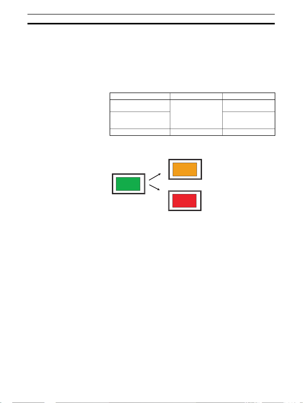
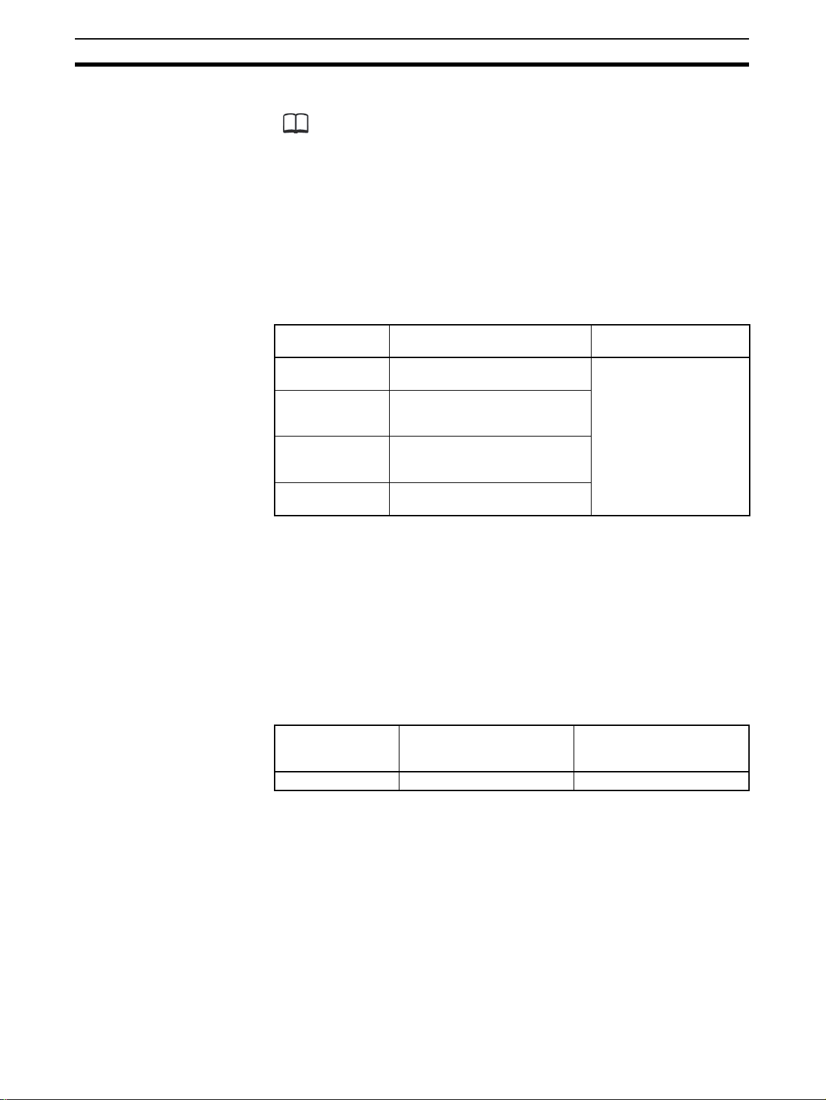
• Switching the backlight of the NV3W(-V1) monochrome, NV4W monochrome, or NV3Q monochrome PTs lets you determine system status
from a distance.
• The NV3Q color PTs can display 4,096 colors.
NV Series Display color Backlight color
NV3W-MG(-V1) and NV4WMG(-V1)
NV3W-MR(-V1), NV4WMR(-V1), and NV3Q monochrome
NV3Q color 4,096 colors ---
Application Example That Switches the Backlight Colo
Color That Indicates
Normal Operation
"Green"
Monochrome Green, orange, or red
White, red, and pink
Color That Indicates an Alarm
"Orange"
Color That Indicates an Alarm
"Red"
Bright LEDs, Eliminate the
Bright LED are used in the PT, eliminating the need to replace the backlights.
need to Replace
Backlights
Each Screen Creation The screens displayed on an NV-series PT are created on the NV-Designer.
Screens can be easily created by simply selecting parts from a library and
arranging them.
Parts are available to match the application that is used.
The NV3W is connected using a special RS-232C cable. The NV3W-V1,
NV4W or NV3Q is connected using a commercially available USB cable.
Convert the PT Model for
Screen Data
Communicate with
OMRON PLCs using Host
Link
The NV model conversion function enables screen data to be converted and
reused from a model with a small screen to one with a large screen.
You can connect the PT to an OMRON CP-series, CS/CJ-series, C-series, or
CVM1/CV- series PT using the Host Link protocol.
Communications with PLCs is possible using RS-232C or RS-422A connections.
Multivendor Support with
PLC Model Conversion
You can connect the PT to OMRON PLC or many other global PLC manufacturers.
Even if you are using different PLCs for different systems, you can easily convert the PLC model in the screen data.
Supply Power to the PT
via the PLC Connecting
Cable (NV3W(-V1) Only)
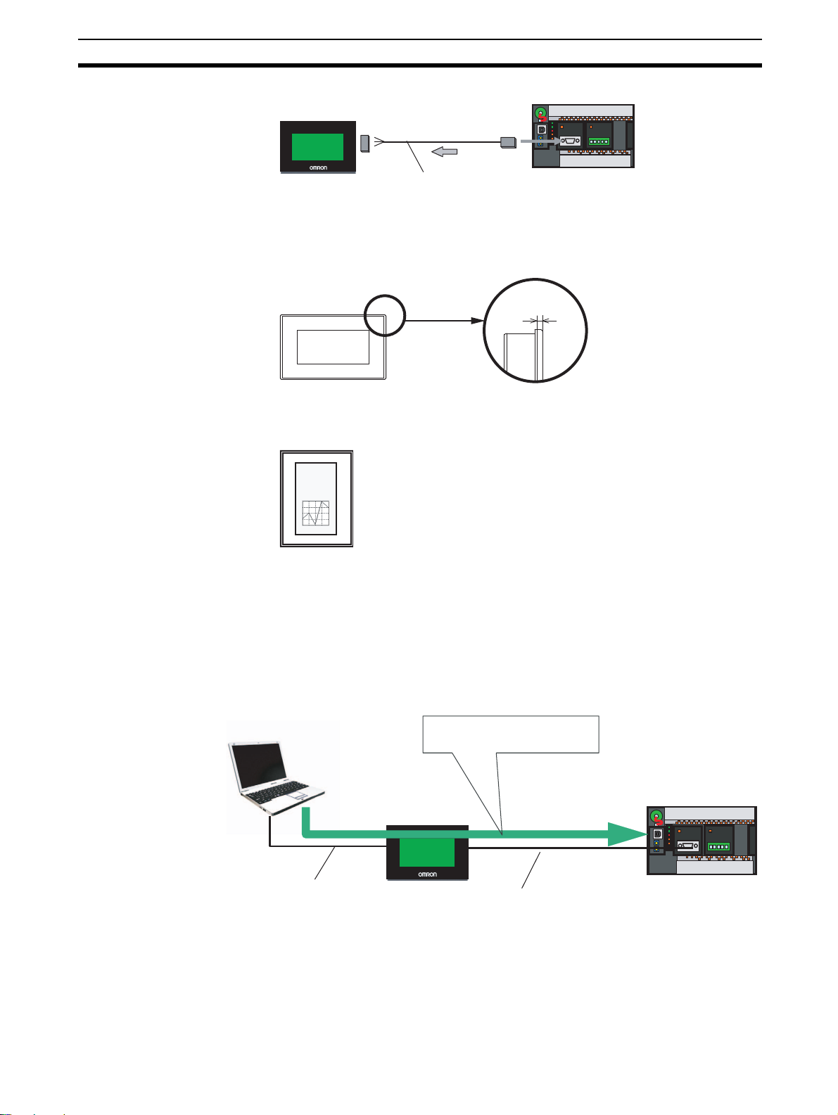
With 5-V NV3W(-V1) models, 5 V can be supplied from the CS/CJ-series or
CP-series PLC via the PLC Connecting Cable. This eliminates the need for a
power supply for the PT, thereby reducing wiring work.
2
Page 23
Features of NV-series PTs Section 1-1
CS/CJ-series or CP-series PLC
NV3W-M@20L
Host Link connection
PLC Connecting Cable
with 5-V Line
Space-saving Installation The compact size and thin design save space when mounting.
With the edge protruding only 4 mm from the panel surface, the PT is also
attractive in appearance.
The NV3W(-V1) or NV4W can be installed vertically for vertical screen displays.
5-V power supply
4 mm
Construction with
Resistance to the
Environment
Transfer, Monitor, or
Debug Ladder Diagrams
from the CX-Programmer
Connected to the PT
Computer running NV-Designer
Temperature
Monitor
SP: 300
PV: 299
The NV3W and NV3Q provide IP65 protection against dust and water drops.
The NV3W-V1 and NV4W provides IP67 protection.
You can transfer, monitor, or debug ladder diagrams in a PLC from the CXProgrammer running on a computer connected to the PT with the convenient
SPMA (Single Port Multiple Access) function while the PLC and PT are communicating with each other.
This function is effective during system installation and debugging.
CX-Programmer
Communicate through the PT.
Ladder diagrams can be transferred
and the PLC can be monitored from
the CX-Programmer.
CS/CJ/CP-series PLC
Host Link connection
Use the same cable as
for the NV-Designer.
Reduce the Load on the
PLC with the Write
Address Function
Also, there is no need to change the
cable between the PT and PLC.
Note The CX-Programmer and NV-Designer, however, cannot be con-
nected online at the same time.
You can use the W rite Address fu nction to execute operations to set or reset
bits, set values, perform calculations, and more in PLC memory when conditions in the PLC are met. This reduces the load on the ladder program in the
PLC in communicating with the PT.
3
Page 24

Features of NV-series PTs Section 1-1
NV
Specified screen
PLC
Writing memory (Write Address)
Condition
met.
Operation
performed.
Condition
met.
Operation
performed.
Condition, such as a
bit turning ON or a
word reaching a value
Set bit, reset bit, write
value, add value, etc.
For example, you can set the Write Bit to write recipes or reset the Data Log/
Alarm History Clear Bit.
Operations are also possible for conditions set for memory in the PT and to
manipulate memory in th e PT.
Switch Label Language You can register up to 16 languages and corresponding character strings for
each part in advance and then change all registered parts at the same time
using a function switch or a command from the PLC.
This allows you to switch the language during operation or s witch t he labe ls in
the same language.
Backup PLC Data in the
PT with the Memory Hold
Function (NV4W and
NV3Q Only and Only
When Battery Is Mounted)
You can constantly back up specified words from the PLC in SRAM in th e PT.
This allows you, for e xample, to bac k up memory areas that are not held in the
PLC when using a CP1E PLC without a battery.
You can also back up the specified data from the internal memory in the PT.
Data Transfer Security You can set a password of up to eight alphanum eric characters f or transferring
screen data from the NV-Designer to an NV-series PT, to prevent screen data
from being transferred when anyone other than the administrator attempts to
read PT screen data.
Operation Security
(NV3W-V1/NV4W/NV3Q
Only)
Transferring Screens with
an SD Memory Card
(NV4W and NV3Q Only)
Communications between
OMRON EJ1 Temperature
Controllers and a ModbusRTU Master (NV3W-V1,
NV4W and NV3Q Only)
Monochrome Displa y with
Eight Shades of Gray
(NV4W Only)
You can set a password for each operation level of a part to restrict displays
and operations.
Security passwords are managed according to operator level.
The screens can be transf er red using an SD m emory card even if the PT cannot be connected to the NV-Designer.
Project data can be transferred directly by using SD memory cards.
The NV3W-V1, NV4W or NV3Q can connect an OMRON EJ1 Temperature
Controller using Modbus-RTU. The EJ1 Temperature Controllers are connected using RS-485 with the PT as the master. Up to 31 Temperature Controllers can be connected.
In addition to the previous monochrome display with two shades of gray, you
can now also select a monochrome display with eight shades of gray for
improved screen display quality.
4
Page 25
System Configuration Section 1-2
1-2 System Configuration
This section describes the types of system configurations in which an NVseries PT can be used.
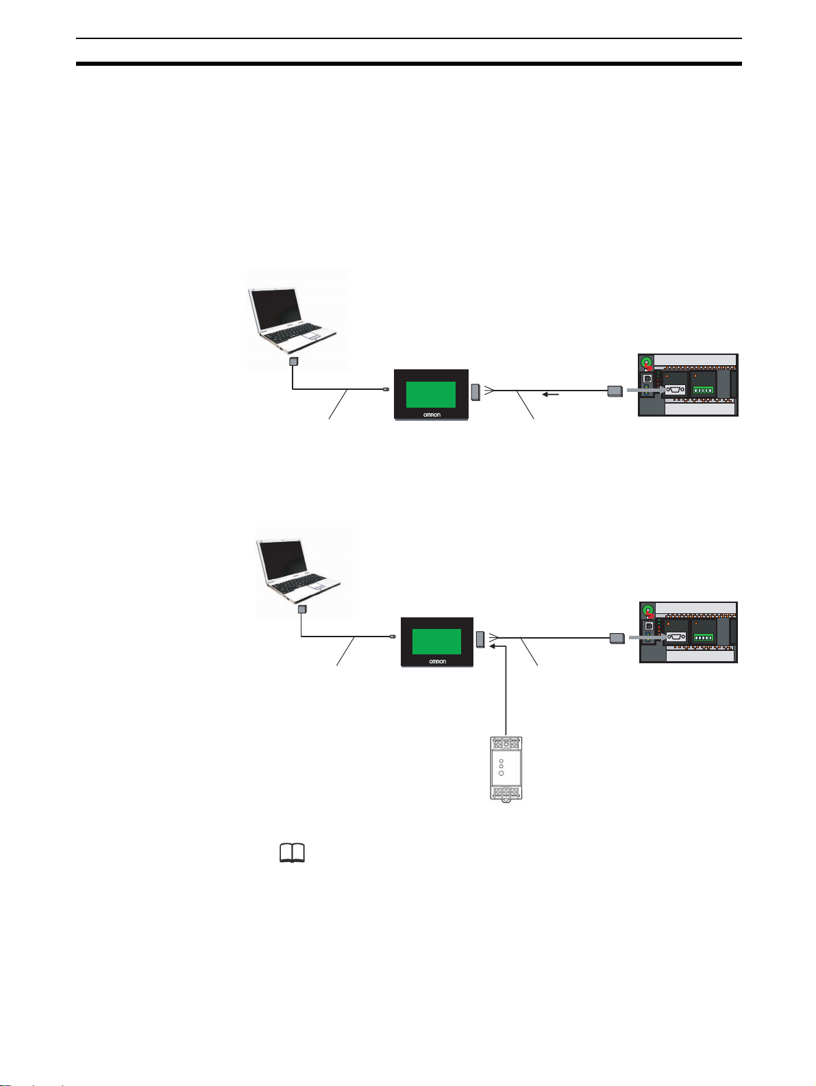
1-2-1 System Configuration
NV3W System
Configuration
■ Using 5-V Power Supplied from the PLC on a Serial Communications
Cable
NV-Designer Screen
Design Software
PLC
NV3W
Host Link connection
5-V power supply
Programming Device
Connecting Cable (RS-232C
cable with a round DIN pin
connector for the NV3W)
NV-TOL-3M
PLC Connecting Cable
XW2Z-200T-4 (2 m with 5-V line)
■ Using an External 24-V Power Supply
NV-Designer Screen
Design Software
NV3W
Programming Device
Connecting Cable (RS-232C
cable with a round DIN pin
connector for the NV3W)
NV-TOL-3M
Additional Information
To connect to a USB connector on the personal computer, insert a CS1W-CIF31
USB-Serial Conversion Cable as shown below.
Host Link connection
PLC Connecting Cable
XW2Z-200T-3 (2 m without 5-V line)
XW2Z-500T-3 (5 m without 5-V line)
24-V power supply
PLC
5
Page 26
System Configuration Section 1-2
NV-Designer Screen
Design Software
Host Link connection
NV3W-V1
PLC
5-V power supply
PLC Connecting Cable
XW2Z-200T-4 (2 m with 5-V line)
Commercially available USB
cable (Type mini-B)
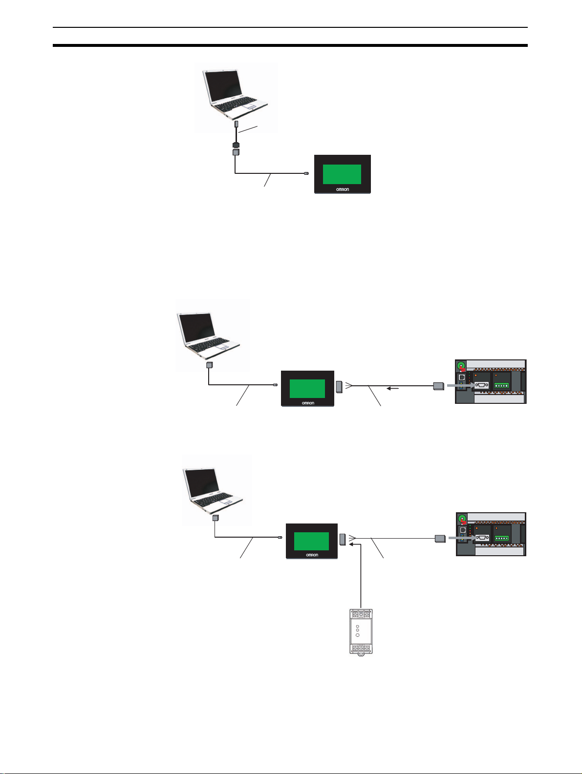
NV-Designer Screen
Design Software
Note: The USB driver included with the
CS1W-CIF must be installed.
USB-Serial Conversion Cable
CS1W-CIF31
NV3W
Programming Device
Connecting Cable (RS-232C
cable with a round DIN pin
connector for the NV3W)
NV-TOL-3M
NV3W-V1 System
Configuration
■ Using 5-V Power Supplied from the PLC on a Serial Communications
Cable
6
■ Using an External 24-V Power Supply
NV-Designer Screen
Design Software
NV3W-V1
Commercially available USB
cable (Type mini-B)
PLC
Host Link connection
PLC Connecting Cable
XW2Z-200T-3 (2 m without 5-V line)
XW2Z-500T-3 (5 m without 5-V line)
24-V power supply
Page 27
System Configuration Section 1-2
Commercially available USB cable
(Type mini-B)
Modbus-RTU
24-V power supply
NV-Designer Screen
Design Software
RS-485
EJ1 Modular
Temperature Controller
EJ1 Modular
Temperature Controller
Up to 31 Temperature
Controllers can be
connected.
NV3W-V1
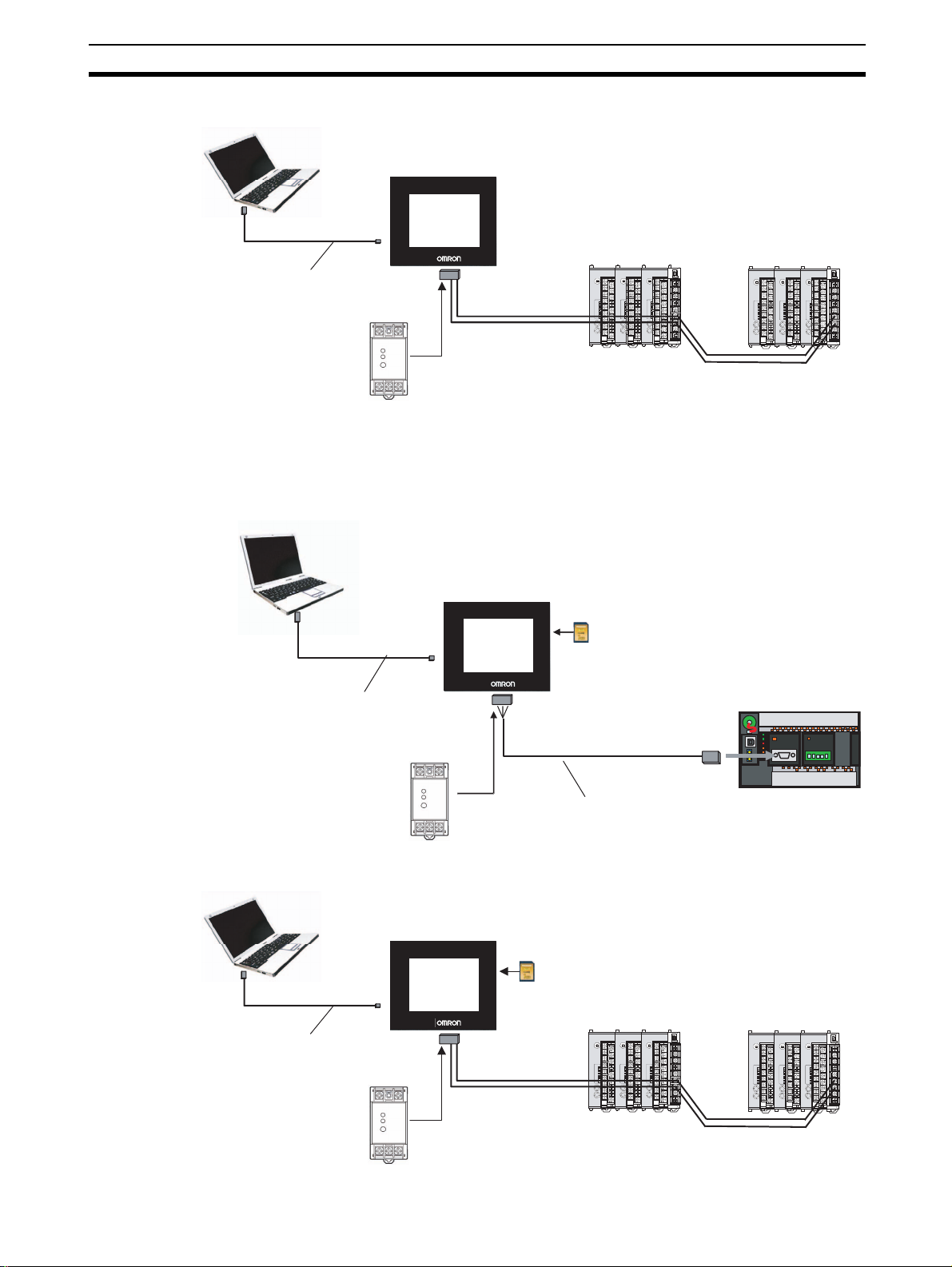
NV-Designer Screen
Design Software
Commercially available USB cable
NV4W or NV3Q
SD memory card
(Used to backup and restore
screen data.)
Host Link connection
PLC Connecting Cable
XW2Z-200T-3 (2 m without 5-V line)
XW2Z-500T-3 (5 m without 5-V line)
24-V power supply
PLC
*1
*1 NV3Q: Type B
NV4W: Type mini-B
■ Connecting Temperature Controllers
NV4W/NV3Q System
Configuration
■ Connecting PLCs
■ Connecting Temperature Controllers
NV-Designer Screen
Design Software
Commercially available USB cable
*1 NV3Q: Type B
NV4W: Type mini-B
24-V power supply
NV4W or NV3Q
*1
SD memory card
(Used to backup and restore
screen data.)
EJ1 Modular
Temperature Controller
Modbus-RTU
RS-485
EJ1 Modular
Temperature Controller
Up to 31 Temperature
Controllers can be
connected.
7
Page 28
System Configuration Section 1-2
Additional Information
NV-series PTs do not support the 1:N NT Link protocol. Modbus-RTU (PLC:
Master, PTs: Slaves) is required to connect multiple NV-series PTs to one PLC.
(Up to 31 PT can be connected.)
To use Modbus, a communications program for the master is required in the
PLC. Also, notification cannot be performed from the PT. Therefore, response
and updating may be slow or it may not be possible to read all inputs of touch
switches, lamps, and numbers.
For details, ref e r to the NV-series Host Connection Manual (Cat. No. V105).
1-2-2 Connectable OMRON PLCs
Series PLC Serial communications
CP Series N-type CP1E, CP1L (except for 10-
point models), and CP1H
CS/CJ Series CS1G/CS1H, CS1G-H/CS1H-H,
CS1D, CJ1G, CJ1G-H/CJ1H-H,
CJ1M, CJ2H and CJ2M
C Series
CVM1/CV Series
*1
C200HX/HG/HE(-Z), CQM1H,
CPM2A/CPM2C, CPM1/CPM1A,
and SRM1-C02-V2
*1
CV500, CV1000, CV2000, and
CVM1
*1 If the PT is connected to a C-series or CV/CVM1-series PLC, keep the
PLC in MONITOR mode. If the PLC is in RUN mode and the PT attempts
to write to PLC memory, an error code of ER01 will be displayed and memory will not be written. If the PT is connected to a CP-ser ies or CS/CJseries PLC, the PLC can be in either RUN or MONITOR mode.
You can connect to th e PLC using a built-in serial port on the CPU Unit, a
serial port on a Serial Communications Unit (includes serial connection
through peripheral port), Serial Communications Board, or Host Link Unit.
Use RS-232C or RS-422A to connect to OMR ON PLCs. Do not use RS-485.
1-2-3 Connectable OMRON Temperature Controllers
Series Temperature Controllers Serial communications
EJ1 Series EJ1 Modbus-RTU
mode for PT connection
Host Link
mode for connecting to NV-
series PT
The NV3W-V1, NV4W or NV3Q can connect to OMRON EJ1 Temperature
Controllers using Modbus-RTU. The EJ1 Temperature Controllers are connected using RS-485 with the PT as the master. Up to 31 Temperature Controllers can be connected.
8
Page 29
Models Section 1-3
1-3 Models
This section provides a list of the models of PTs in the NV Series.
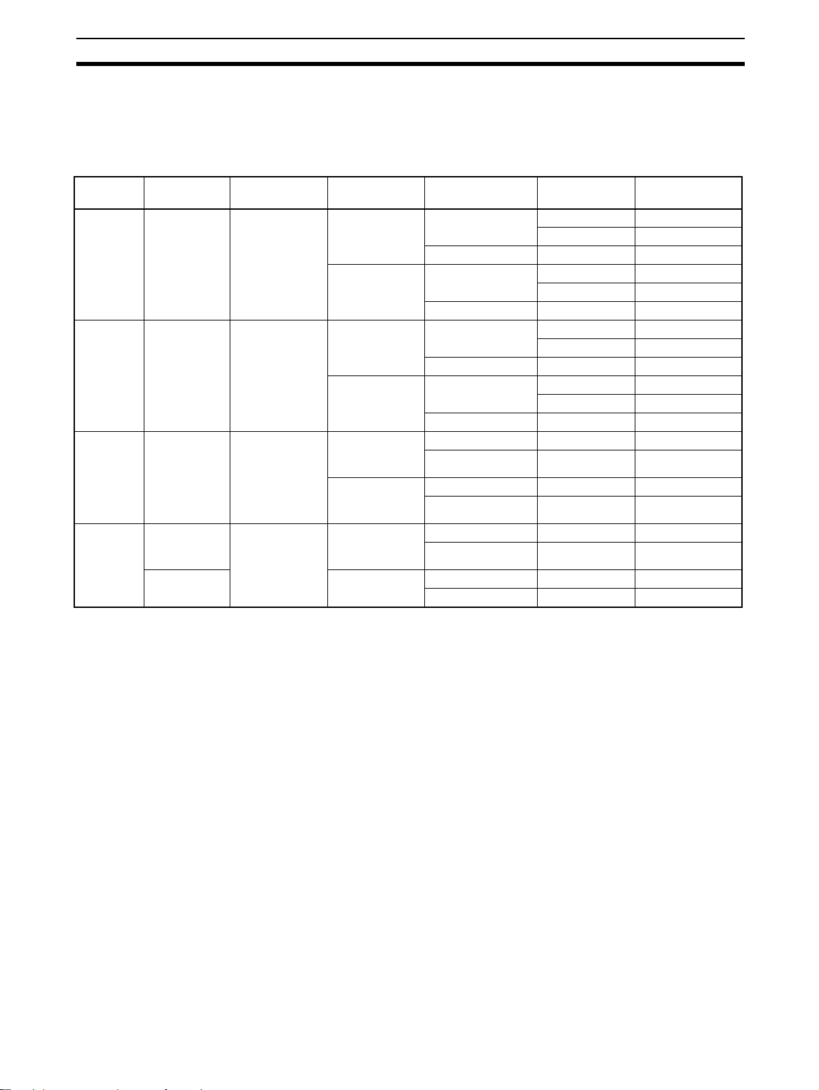
1-3-1 NV-series PTs
Screen size Number of
NV3W PT 3.1-in, STN
monochrome
NV3W-V1 PT3.8-in, STN
monochrome
NV4W PT 4-in, STN
monochrome
NV3Q PT 3.6-in, STN
monochrome
3.6-in, TFT
color
dots
128 × 64 dots LEDs, 3 colors
240 × 96 dots LEDs, 3 colors
320 ×120 dots LEDs, 3 colors
320 ×240 dots
(QVGA)
Backlight Communications Power supply
(green, orange,
and red)
LEDs, 3 colors
(white, pink,
and red)
(green, orange,
and red)
LEDs, 3 colors
(white, pink and
red)
(green, orange,
and red)
LEDs, 3 colors
(white, pink,
and red)
LEDs, 3 colors
(white, pink,
and red)
White LED RS-232C 24 VDC NV3Q-SW21
voltage
Model
RS-232C 5 VDC NV3W-MG20L
24 VDC NV3W-MG20
RS-422A/485 24 VDC NV3W-MG40
RS-232C 5 VDC NV3W-MR20L
24 VDC NV3W-MR20
RS-422A/485 24 VDC NV3W-MR40
RS-232C 5 VDC NV3W-MG20L-V1
24 VDC NV3W-MG20-V1
RS-422A/485 24 VDC NV3W-MG40-V1
RS-232C 5 VDC NV3W-MR20L-V1
24 VDC NV3W-MR20-V1
RS-422A/485 24 VDC NV3W-MR40-V1
RS-232C 24 VDC NV4W-MG21
RS-422A/485 24 VDC NV4W-MG41
RS-232C 24 VDC NV4W-MR21
RS-422A/485 24 VDC NV4W-MR41
RS-232C 24 VDC NV3Q-MR21
RS-422A/485 24 VDC NV3Q-MR41
RS-422A/485 24 VDC NV3Q-SW41
9
Page 30
Models Section 1-3
PT end
Computer end (RS-232C connector)
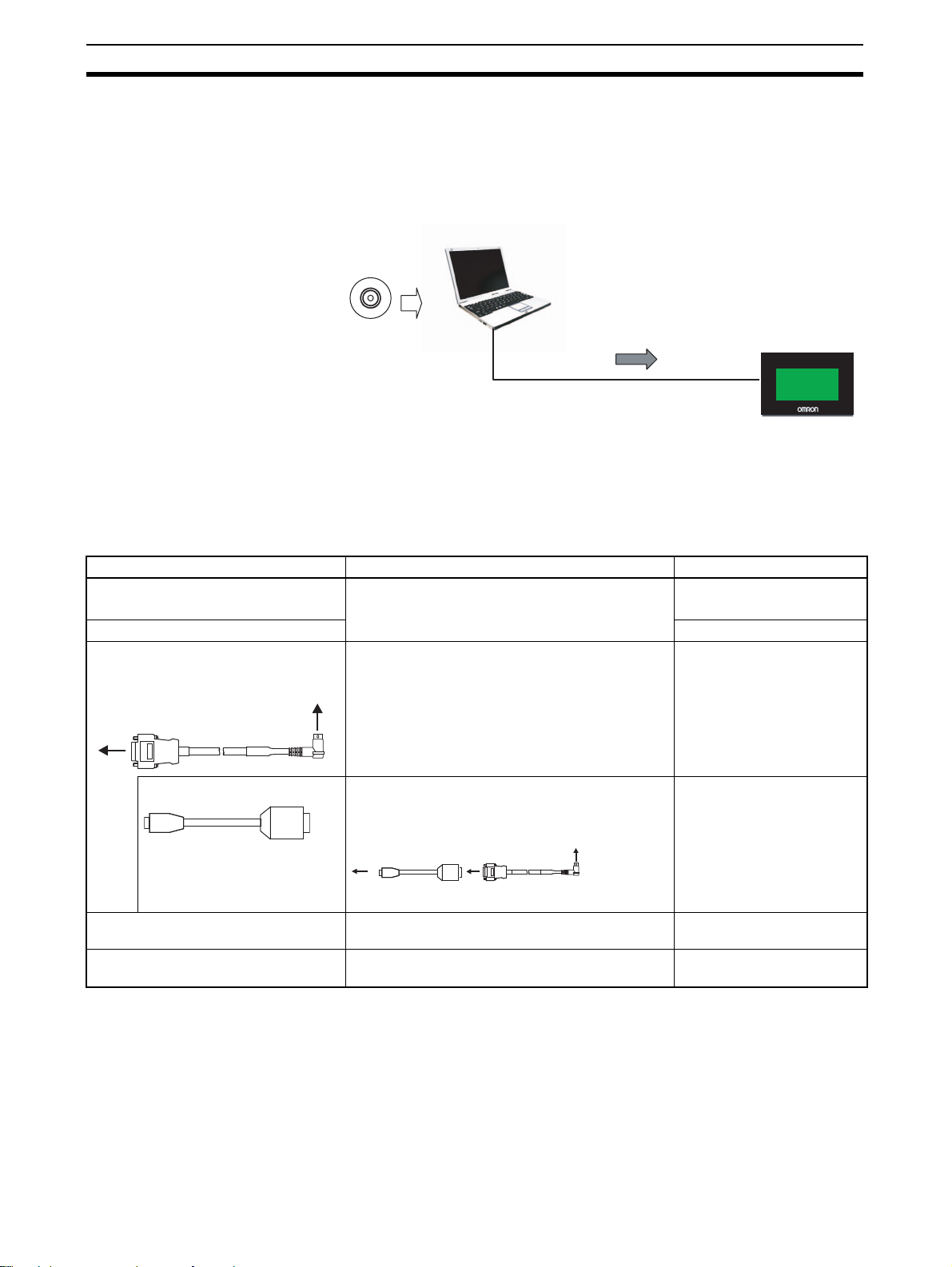
1-3-2 Screen Design Software
The NV-Designer is used as the Screen Design Software for the NV-series
PTs.
The NV -Designer is included in CX-One version 4.@ or in CX-One Lite version
4.@.
Personal computer
CX-One version 4.@ or
CX-One Lite version 4.@
NV-Designer Screen
Design Software
Project data is transferred.
NV
• The NV3W is connected using an NV-TOL-3M RS-232C Cable with a
round DIN pin connector on the NV end.
To connect to a USB connector on the computer, connect the NV-TOL-3M
cable through a CS1W-CIF31 USB-Serial Conversion Cable.
• You can connect to the NV3W-V1, NV4W or NV3Q using a commercially
avail able USB cable.
Name Description Model
CX-One version 4.@ Includes the NV-Designer. On CD: CXONE-AL01C-V4
On DVD: CXONE-AL01D-V4
CX-One Lite version 4. @ On CD: CXONE-L T01C-V4
Programming Device Connecting
Cable for NV3W
USB-Serial Conversion Cable For the NV3W (sold separately)
For the NV3W (sold separately) RS-232C cable
with a round DIN pin connector on the NV3W end
Use this Cable together with the NV-TOL-3M to
connect to a USB connector on the computer.
Computer end (USB connector)
PT end
NV-TOL-3M
CS1W-CIF31
Programming Device Connecting
Cable for NV3W-V1 or NV4W
Programming Device Connecting
Cable for NV3Q
10
Note The enclosed USB driver must be installed.
For the NV3W-V1 or NV4W (sold separately)
(USB: Type mini-B)
For the NV3Q (sold separately)
(USB: Type B)
Commercially available USB
cable
Commercially available USB
cable
Page 31

Models Section 1-3
PLC
XM2S-09
PT end PLC end
1-3-3 Other Optional Products
Name Description Model
PLC Connecting Cable For the NV3W(-V1) with 5-V
power (sold separately)
For the NV3W(-V1), NV4W, and
NV3Q (sold separately)
Battery For the NV4W, and NV3Q (sold
separately)
XW2Z-200T-4 (2 m with 5-V line)
XW2Z-200T-3 (2 m without 5-V line)
XW2Z-500T-3 (5 m without 5-V line)
NV-BAT01
Display Protective Sheets For the NV3W, contains 10 sheets
(sold separately)
For the NV3W-V1, contains 10
sheets (sold separately)
For the NV4W , contains 10 sheets
(sold separately)
For the NV3Q, contains 10 sheets
(sold separately)
Waterproof Packings For the NV3W, contains 10 pack-
ings (sold separately)
For the NV4W, contains 10 pack-
ings (sold separately)
For the NV3Q, contains 10 pack-
ings (sold separately)
SD memory card For the NV4W/NV3Q
Memory capacity: 32 MB to 2 GB
For backing up and restoring base
screen data for the PT (except fo r
the NV3W(-V1)) and NV-Designer .
*1 This does not apply to NV3W-V1.
*2 The capacity of the SD memory card is 32 MB to 1 GB for system program
version 1.0@ of the NV3Q-series PT.
NV3W-KBA04
NV3W-KBA04-V1
NV4W-KBA04
NV3Q-KBA04
NV3W-RP001
NV4W-RP001
*1
One Packing is provided
on the PT as a standard
feature.
NV3Q-RP001
Commercially available SD cards
Panasonic card with capacity of 32 MB to 2 GB
*2
11
Page 32

Specifications Section 1-4
+10+1
0
1-4 Specifications
1-4-1 NV3W
General Specifications
Item Specifications
Type 24 V 5 V
Model NV3W-M@20 and NV3W-M@40 NV3W-M@20L
Rated power supply 24 VDC 5 VDC
Operating voltage range 21.6 to 26.4 VDC 4.5 to 5.5 VDC
Pow er consumption (current con-
sumption)
Ambient operating temperature 0 to 50°C
Ambient operating humidity 20% to 85% (with no condensation)
Ambient storage temperature −20 to 60°C
Ambient storage humidity 10% to 85% (with no condensation)
Dielectric strength Between the power supply terminals and the case
Insulation resistance Between the power supply terminals and the case
Vibration resistance 10 to 55 Hz with 0.75-amplitude for 10 min each in X, Y, and Z directions, 1 sweep per
Shock resistance
Noise immunity 1,000 V
Resistance to environment IP65 (at initial state)
Dimensions 110 × 72 × 28 mm (W × H × D)
Panel cutout dimensions
Degree of protection Operating section on front panel: IP65
Safety standards UL 508, EC Directives and Korea Certification Mark
Weight 160 g max.
2 W max. (80 mA max.) 1 W max. (200 mA max.)
500 VAC for 1 min with a cutoff current of 10 mA (at initial state)
100 MΩ (at 500 VDC) (at initial state)
min
98 m/s2 4 times each in X, Y, and Z directions
with pulse widths of 50 ns and 1 μs between power supply terminals (via
simulator)
Dust proof and drip proof only from the front of the panel (using Waterproof Packing at
the contact surface with the panel)
*Replace the Waterproof Packing each time you reinstall the PT.
105.0 × 67.0 mm (H × V), Panel thickness: 1.6 to 4.8 mm
p-p
12
Page 33

Specifications Section 1-4
Performance Specifications
Item Specifications
Type All NV3W models
Model NV3W-MG@@(@) and NV3W-MR@@(@)
Display device STN monochrome LCD
Number of dots 128 × 64 dots (H × V)
Effective display size 70 × 35 mm (H × V)
Life expectancy
Backlights NV3W-MG: LED backlights, 3 colors (green, orange, and red)
Touch switches Method Analog resi stance membrane
Operating force 0.5 N max.
Life expectancy 100 million operations min. (at 25°C)
Switches
Size
External memory --Host communications NV3W-MS@20(@): RS-232C (not isolated), Transmission distance: 15 m,
Support Software communications RS-232C (not isolated) via Mini DIN 5-pin connector
Applicable Support Software NV -Designer v ersion 1.0 or higher (Included with CX-One version 4.@ or in
50,000 hours min.
NV3W-MR: LED ba cklights, 3 colors (white, pink, and red)
50 max. per screen
8 dots × 8 dots min.
Connector: 8-pin)
NV3W-M@40: RS-422A/485 (not isolated), Transmission distance: 500 m,
Connector: 8-pin)
CX-One Lite version 4.@.)
*1
*2
*3
*1 This is the estimated time before brightness is reduced by half at room
temperature and humidity. It is not a guaranteed value.
*2 The estimate applies to operation when only custom switches are placed
on the screen.
*3 This is the effective area of a touch switch. It does not include the 1-dot
frame line.
13
Page 34

Specifications Section 1-4
Functional Specifications
Item Specifications
Type All NV3W models
Displayable fonts Fixed (NV-Designer): Half-size characters (8 × 8 dots) or normal characters
Displayable characters Japanese, English, Korean, German, French, Italian, Spanish, Simplified
Maximum number of screens Approx. 160 screens
Screen numbers that can be registered Base screens: 0 to 1,023
Screen types Base screens (These screens can be switched externally and parts can be
Graphics Straight lines, continuous lines, rectangles, circles, ovals, circular arcs, oval
Parts Messages, lamps, switches, data, bar graphs, keyboards, line graphs, and
Other functions Recipes, flowing displays, address writing, and language switching
SPMA functions Communications with a PLC are possible if the computer running the CX-
(8 × 16 dots) (Magnification is possible on the display to 1×, 2×, and 4×.)
True Type (NV-Designer): 10 to 64 dots
Windows: 10 to 64 dots
Chinese, Traditional Chinese, Turkish, Russian, and Vietnamese
*The number of screens that can be registered depends on the contents of
the screens.
Keyboard screens: 0 to 7
pasted on these screens.)
Keyboard screens (These screens can be used to directly enter data for data
parts.)
arcs, sectors, oval sectors, rounded rectangles, and bitmaps
clocks*
*Clock parts can access external clock data and display it. There is no clock
in the PT itself.
Programmer is connected to the tool port and a CS/CJ/CP-series PLC is
connected to the COM port.
Memory Specifications
Item Type
Type All NV3W models
Memory type FROM (built-in Flash Memory)
Memory capacity
384 Kbytes
*1
*1 Refer to 1-4-5 Battery Backup for the data that is saved in memory.
14
Page 35

Specifications Section 1-4
Communications Interface Specifications
PLC/External Device Interface
■ COM Port
Item Specifications
Type RS-232C RS-422A/485
Model NV3W-M@20(@)NV3W-M@40
Communications standard RS-232C (not isolated)
Communications
conditions for
external device
Transmission distance (total length) 15 m max. (baud rate: 19,200 bps) 500 m max. (baud rate: 115,200 bps)
Protocols •Host Link (OMRON protocol for PLCs)
Connector
Applicable cable PLC Connecting Cable
Baud rate (bps) 9,600, 19,200, 38,400, 57,600, 115,200
Data length 7 or 8 bits
Parity None, even, or odd
Stop bits 1 bit
•Modbus-RTU
•Protocols for PLCs from other companies (Refer to the NV-series PT Host Connec-
tion Manual (Cat. No. V105) for details.)
8-pin connector
(Without 5-V line: XW2Z-200T-3 (2 m) or
XW2Z-500T-3 (5 m),
with 5-V line: XW2Z-200T-4 (2 m))
*2*3*4
RS-422A/485 (not isolated)
Shielded twisted-pair cable
*1
*1 The PTs cannot be connected to OMRON PLCs using RS-485 (2-wire)
connections and the Host Link protocol.
*2 “+” and “−” are the power supply pins to drive the PT.
*3 Be sure to consider the cable length and ensure that the voltage supplied
to the PT is within the operating voltage range.
*4 If power is being supp lied from a source other than the PLC f or a PT with a
5-VDC power supply, make sure the power supply cable is 10 m or less in
length.
Transfer Interface for Screen Data
■ Tool Port
Item Specifications
Communications standard RS-232C (not isolated)
Communications
conditions for NVDesigner
Protocols Special protocol for NV -series PTs
Connector Mini DIN 5-pin connector
Applicable cable NV-TOL-3M
Baud rate (bps) Always 115,200
Data length Always 8 bits
Parity Always no parity
Stop bits 1 bit
15
Page 36

Specifications Section 1-4
+10+1
0
1-4-2 NV3W-V1
General Specifications
Item Specifications
Type 24 V 5 V
Model NV3W-M@20-V1 and NV3W-M40-V1 NV3W-M@20L-V1
Rated power supply 24 VDC 5 VDC
Operating voltage range 21.6 to 26.4 VDC 4.5 to 5.5 VDC
Power consumption (current
consumption)
Ambient operating temperature 0 to 50°C
Ambient operating humidity 20% to 85%RH (with no condensation)
Ambient storage temperature −20 to 60°C
Ambient storage humidity 10% to 85%RH (with no condensation)
Dielectric strength Between the power supply terminals and the case
Insulation resistance Between the power supply terminals and the case
Vibration resistance
Shock resistance
Noise immunity 1,000 V
Resistance to environment IP67 (at initial state)
Dimensions 112 × 74 × 27 mm (W × H × D)
Panel cutout dimensions
Degree of protection Operating section on front panel: IP67
Safety standards UL 508, EC Directives and Korea Certification Mark
Weight 170 g max.
1.9 W max. (80 mA max.) 1 W max. (200 mA max.)
500 VAC for 1 min with a cutoff current of 10 mA (at initial state)
100 MΩ (at 500 VDC) (at initial state)
2
5 to 8.4 Hz, 3.5 mm single amplitude, 8.4 to 150 Hz, 9.8m/s
directions (1 octave/min)
2
147 m/s
ulator)
Dust proof and drip proof only from the front of the panel (using Waterproof Packing at
the contact surface with the panel)
*Replace the Waterproof Packing each time you reinstall the PT.
105.0 × 67 mm (H × V), Panel thickness: 1.6 to 4.8 mm
min. 3 times each in x, y, and z directions
with pulse widths of 50 ns and 1 µs between power supply terminals (via sim-
p-p
, 10 times each in x, y , and z
16
Page 37

Specifications Section 1-4
Performance Specifications
Item Specifications
Type All NV3W-V1 models
Model NV3W-MG@@(L)-V1/NV3W-MR@@(L)-V1
Display device STN monochrome LCD
Number of dots 240 × 96 dots (H × V)
Effective display size 88.5 × 35.4 mm (H × V)
Life expectancy
Backlights NV3W-MG@@(L)-V1: LED backlights, 3 colors (green. orange and red)
Touch switches Method Analog resistance membrane
Operating force 0.8 N max.
Life expectancy 100 million operations min. (at 25°C)
Switches
Size
Host communications NV3W-M@20(L)-V1: RS-232C (not isolated), Transmission distance: 15 m,
Support Software communications USB 1.1 Mini-B, Transmission distance: 5 m max.
Applicable Support Software NV -Designer version 2.0 or higher (Included with CX-One version 4.34 or in
50,000 hours min.
NV3W-MR@@-V1: LED backlights, 3 colors (white, pink and red)
50 max. per screen
8 dots × 8 dots min.
Connector: 8-pin
NV3W-M@40-V1: RS-422A/485 (not isolated), Transmission distance: 500 m,
Connector: 8-pin
CX-One Lite version 4.34.)
*1
*2
*3
*1 This is the estimated time before brightness is reduced by half at room
temperature and humidity. It is not a guaranteed value.
*2 The estimate applies to operation when only custom switches are placed
on the screen.
*3 This is the effective area of a touch switch. It does not include the 1-dot
frame line.
17
Page 38

Specifications Section 1-4
Functional Specifications
Item Specifications
Type All NV3W-V1 models
Displayable fonts Fixed (NV-Designer): quarter square character (8 × 8 dots), half-size character (8 × 16 dots) or nor-
Displayable characters
Maximum number of
screens
Screen numbers that
can be registered
Screen types Base screens (These screens can be switched externally and parts can be pasted on these
Graphics Straight lines, continuous lines, rectangles, circles, ovals, circular arcs, ov al arcs, sectors, oval sec-
Parts
Other functions Recipes, flow displays, address writing, display language switching, alarm lists, passwords, and
SPMA functions Communications with a PLC are possible if the computer running the CX-Programmer is con-
mal characters (16 × 16 dots) (Magnification is possible on the display to 1×, 2×, 4× and 8×.)
True Type (NV-Designer): 10 to 96 dots
Windows: 10 to 96 dots
Japanese, English, Korean, German, French, Italian, Spanish, Simplified Chinese, Traditional Chi-
nese, Turkish, Russi an, and Vietnamese
Approx. 250 screens
*The number of screens that can be registered depends on the contents of the screens.
Base screens: 0 to 1,023
Keyboard screens: 0 to 7
screens.)
Keyboard screens (These screens can be used to directly enter data for data parts.)
tors, and rounded rectangles
Messages, lamps, switches, data, bar graphs, keyboards, line graphs, alarm lists, and clocks
*Clock parts can access external clock data and display it.
*The PLC features no function of watch.
multifunction
nected to the USB port and a CS/CJ/CP-series PLC is connected to the COM port.
*
Memory Specifications
Item Specifications
Type Monochrome
Model All the NV3W-V1 models
Base screen data, keyboard
screen data, and flow display
data
Recipe data Memory type FROM (built-in Flash Memory)
Write Address Memory type FROM (built-in Flash Memory)
Memory type FROM (built-in Flash Memory)
Memory capacity
Memory capacity
Memory capacity
2048 Kbytes
64 Kbytes
64 Kbytes
*1
*1
*1
*1 Refer to 1-4-5 Battery Backup for the data that is saved in memory.
18
Page 39

Specifications Section 1-4
Communications Interface Specifications
PLC/External Device Interface
Items Specifications
Type RS-232C RS-422A/485
Model NV3W-M@20(@)-V1 NV3W-M@40-V1
Communications standard RS-232C (not isolated)
Communications
conditions for
external device
Transmission distance (total length) 15 m max.
Protocols •Host Link (OMRON protocol for PLCs)
Connector
Applicable cable PLC connecting cable for OMRON Host
Baud rate (bps) 9,600, 19,20 0, 38,400, 57,600, or 115,200
Data length 7 or 8 bits
Parity None, even, or odd
Stop bits 1 bit
(baud rate: 19,200 bps)
•Modbus-RTU
•Protocols for PLCs from other companies (Refer to the NV-series PT Host Connec-
tion Manual (Cat. No. V105) for details.)
8-pin connector
link (Without 5-V line: XW2Z-200T-3(2m)
or XW2Z-500T-3(5m), with 5-V line:
XW2Z-200T-4 (2 m))
*2*3*4
RS-422A/485 (not isolated)
500 m max.
(baud rate: 115,200 bps)
Shielded twisted-pair cable
*1
*1 The PTs cannot be connected to OMRON PLCs using RS-485 (2-wire)
connections and the Host Link protocol.
*2 “+” and “−” are the power supply pins to drive the PT.
*3 Be sure to consider the cable length and ensure that the voltage supplied
to the PT is within the operating voltage range.
*4 If power is being supp lied from a source other than the PLC f or a PT with a
5-VDC power supply, make sure the power supply cable is 10 m or less in
length.
Transfer Interface for Screen Data
■ USB port
Type All the NV3W-V1 models
Communications standard USB 1.1
Connector type
Number of PTs connected to
computer
Transmission distance 5 m max.
Protocols Special protocol for NV-series PTs
Applicable cable Commercially available USB cable
*1 Do not subject the metal parts of the connector to excessive static electric-
ity.
Item Specifications
*1
USB type mini-B
1
19
Page 40

Specifications Section 1-4
+10+1
0
1-4-3 NV4W
General Specifications
Item Specifications
Type Monochrome
Model NV4W-M@@1
Rated power supply 24 VDC
Operating voltage range 21.6 to 26.4 VDC
Power consumption (current
consumption)
Powe r supply section isolation Transformer
Ambient operating tempera-
ture
Ambient operating humidity 20% to 85% (with no condensation)
Ambient storage temperature −20 to 60°C
Ambient storage humidity 10% to 85% (with no condensation)
Dielectric strength
Insulation resistance
Vibration resistance
Shock resistance
Noise immunity 1,000 V
Resistance to environment IP67 (at initial state)
Dimensions 146 × 74 × 30 mm (W × H × D)
Panel cutout dimensions
Degree of protection Operating section on front panel: IP67
Battery life expectancy Battery life expectancy: 5 yr (at 25°C)*
Battery backup PT clock data, PLC memory hold data, PT internal memory hold data, and alarm history
Safety standards UL 508 and EC Directives
Weight 240 g max.
*1
*1
1.7 W max. (70 mA max.)
0 to 50°C
Between the power supply terminals and the case
500 VAC for 1 min with a cutoff current of 10 mA (at initial state)
Between the power supply terminals and the case
100 MΩ (at 500 VDC) (at initial state)
2
5 to 9 Hz, 3.5-mm single amplitude, 9 to 150 Hz, 9.8 m/s
directions (1 octave/min)
2
147 m/s
lator)
Dust proof and drip proof only from the front of the panel (using Waterproof Packing at the
contact surface with the panel)
*Replace the Waterproof Packing each time you reinstall the PT.
139 × 67 mm (H × V), Panel thickness: 1.6 to 4.8 mm
*The SRAM (internal RAM) is backed up by the battery . If backing up the data is required,
purchase a Battery separately.
The battery life expectancy is for when no power is supplied. The actual value may be
shorter depending on application conditions.
data (if Battery is mounted)
*Purchase an NV-BAT01 separately.
3 times each in X, Y, and Z directions
with pulse widths of 50 ns and 1 μs between power supply terminals (via simu-
p-p
, 10 times each in X, Y, and Z
*1 The USB port and COM port are not isolated from the internal digital cir-
cuits.
20
Page 41

Specifications Section 1-4
Performance Specifications
Item Specifications
Model NV4W-M@@1
Display device STN monochrome LCD
Number of dots 320 × 120 dots (H × V)
Effective display size 109 × 41 mm (H × V)
Life expectancy
Backlights NV4W-MG: LED backlight, 3 colors (green, orange, and red)
Grayscale display 2 shades of gray or 8 shades of gray (selectable using NV-Designer)
Touch switches Method Analog resistance membrane
Operating force 0.8 N max.
Life expectancy 100 million operations min. (at 25°C)
Switches
Size
External memo ry SD memory card (32 MB to 2 GB)
Host communications
Support Software communications USB 1.1 Mini-B, Transmission distance: 5 m max.
Applicable Support Software NV-Designer version 1.1 or higher (Included with CX-One version 4.@ or in
COM Port NV4W-M@21: RS-232C (not isolated), Transmission distance: 15 m, Connec-
50,000 hours min.
NV4W-MR: LED backlight, 3 colors (white, pink, and red)
100 max. per screen
8 dots × 8 dots min.
Manufacturers for which operation has been confirmed: Panasonic
SD standard
tor: 8-pin)
NV4W-M@41: RS-422/A485 (not isolated), Transmission distance: 500 m,
Connector: 8-pin)
CX-One Lite version 4.@.)
*1
*2
*3
*4
*1 This is the estimated time before brightness is reduced by half at room
temperature and humidity. It is not a guaranteed value.
*2 The estimate applies to operation when only custom switches are placed
on the screen.
*3 This is the effective area of a touch switch. It does not include the 1-dot
frame line.
*4 Do not reformat the SD memory card using standard Windows functions,
such as Windows Explorer.
21
Page 42

Specifications Section 1-4
Functional Specifications
Item Specifications
Type Monochrome
Model NV4W-M@@1
Displayable fonts Fixed (NV-Designer): Half-size characters (8 × 8 dots) or normal characters (8 × 16 dots) (Magnifi-
Displayable characters
Maximum number of
screens
Screen numbers that
can be registered
Screen types Base screens (These screens can be switched externally and parts can be pasted on these
Graphics Straight lines, continuous lines, rectangles, circles, ovals, circular arcs, ov al arcs, sectors, oval sec-
Parts Messages, lamps, switches, data, bar graphs, keyboards, line graphs, alarm lists, and clocks*
Other functions Recipes, flow displays, address writing, display language switching, alarm lists, alarm history, pass-
SPMA functions Communications with a PLC are possible if the computer running the CX-Programmer is con-
cation is possible on the display to 1×, 2×, 4× and 8×.)
True Type (NV-Designer): 10 to 240 dots
Windows: 10 to 240 dots
Japanese, English, Korean, German, French, Italian, Spanish, Simplified Chinese, Traditional Chi-
nese, Turkish, Russi an, and Vietnamese
2 shades of gray: 250 screens, 8 shades or gray: 200 screens
*The number of screens that can be registered depends on the contents of the screens.
Base screens: 0 to 1,023
Keyboard screens: 0 to 7
screens.)
Keyboard screens (These screens can be used to directly enter data for data parts.)
tors, and rounded rectangles
*Clock parts can access external clock data and display it.
*Clock accuracy is ±180 s per month.
words, and Multifunction Objects
nected to the USB port and a CS/CJ/CP-series PLC is connected to the COM port.
Memory Specifications
Item Specifications
Type Monochrome
Model NV4W-M@@1
Base screen data, keyboard
screen data, and flow display data
Recipe data Memory type FROM (built-in Flash Memory)
Writing memory (Write Address) Memory type FROM (built-in Flash Memory)
PLC memory hold data and PT
internal memory hold data
Memory type FROM (built-in Flash Memory)
Memory capacity 2,048 Kbytes
Memory capacity 64 Kbytes
Memory capacity 64 Kbytes
Used memory SRAM (internal RAM)
*The SRAM (internal RAM) is backed up by the battery. If backing
up the data is required, purchase an NV-BAT01 Battery separately.
Memory capacity PLC/PT Memory Hold Area (24 words max.)
External Memory Specifications
SD Memory Card Slot
Item Specifications
Type All NV4W models
Supported
media
Applicable for-
mat
SD memory card (32 MB to 2 GB)
Manufacturers for which operation has been confirmed: Panasonic
SD standard compliant
22
Note
The SD access indicator will be lit while the SD memory card is being accessed.
Page 43

Specifications Section 1-4
Communications Interface Specifications
PLC/External Device Interface
■ COM Port
Item Specifications
Type RS-232C RS-422A/485
Model NV4W-M@21 NV4W-M@41
Communications standard RS-232C (not isolated)
Communications
conditions for
external device
Transmission distance (total length) 15 m max. (baud rate: 115,200 bps) 500 m max. (baud rate: 115,200 bps)
Protocols Host Link (OMRON protocol for PLCs)
Connector
Applicable cable XW2Z-200T-3 (2 m) or XW2Z-500T-3
Baud rate (bps) 9,600, 19,200, 38,400, 57,600, or 115,200
Data length 7 or 8 bits
Parity None, ev en, or odd
Stop bits 1 bit
Modbus-RTU
Protocols for PLCs from other companies (Refer to the NV-series PT Host Con-
nection Manual (Cat. No. V105) for details.)
8-pin connector
(5 m) PLC Connecting Cable
*2*3
RS-422A/485 (not isolated)
Shielded twisted-pair cable
*1
*1 The PTs cannot be connected to OMRON PLCs using RS-485 (2-wire)
connections and the Host Link protocol.
*2 “+” and “−” are the power supply pins to drive the PT.
*3 Be sure to consider the cable length and ensure that the voltage supplied
to the PT is within the operating voltage range.
Transfer Interface for Screen Data
■ USB port
Type All NV4W models
Communications standard USB 1.1
Connector type
Number of PTs connected to
computer
Transmission distance 5 m max.
Protocols Special protocol for NV-series PTs
Applicable cable Commercially available USB cable
*1 Do not subject the metal parts of the connector to excessive static electric-
ity.
Item Specifications
*1
USB type mini-B
1
23
Page 44

Specifications Section 1-4
+10+1
0
1-4-4 NV3Q
General Specifications
Item Specifications
Type Monochrome Color
Model NV3Q-MR@1 NV3Q-SW@1
Rated power supply 24 VDC
Operating voltage range 21.6 to 26.4 VDC
Power consumption (current
consumption)
Powe r supply section isolation Transformer
Ambient operating tempera-
ture
Ambient operating humidity 20% to 85% (with no condensation)
Ambient storage temperature −20 to 60°C
Ambient storage humidity 10% to 85% (with no condensation)
Dielectric strength
Insulation resistance
Vibration resistance 10 to 55 Hz with 0.75-amplitude for 10 min each in X, Y, and Z directions, 1 sweep per
Shock resistance
Noise immunity 1,000 V
Resistance to environment IP65 (at initial state)
Dimensions 110 × 92.2 × 33.8 mm (W × H × D)
Panel cutout dimensions
Degree of protection Operating section on front panel: IP65
Battery life expectancy Battery life expectancy: 5 yr (at 25°C)* Battery life expectancy: 3 yr (at 25°C)*
Battery backup PT clock data, PLC memory hold data, PT internal memory hold data, and alarm history
Safety standards UL 508 and EC Directives
Weight 240 g max.
*1
*1
2.4 W max. (100 mA max.) 3.6 W max. (150 mA max.)
0 to 50°C
Between the power supply terminals and the case
500 VAC for 1 min with a cutoff current of 10 mA (at initial state)
Between the power supply terminals and the case
100 MΩ (at 500 VDC) (at initial state)
min
2
98 m/s
ulator)
Dust proof and drip proof only from the front of the panel (using Waterproof Packing at
the contact surface with the panel)
*Replace the Waterproof Packing each time you reinstall the PT.
99.2 × 85.2 mm (H × V), Panel thickness: 1.6 to 4.8 mm
*The SRAM (internal RAM) is backed up by the battery. If backing up the data is required,
purchase a Battery separately.
The battery life expectancy is for when no power is supplied. The actual value may be
shorter depending on application conditions.
data (if Battery is mounted)
*Purchase an NV-BAT01 separately.
4 times each in X, Y, and Z directions
with pulse widths of 50 ns and 1 μs between power supply terminals (via sim-
p-p
*1 The USB port and COM port are not isolated from the internal digital cir-
cuits.
24
Page 45

Specifications Section 1-4
Performance Specifications
Item Specifications
Model NV3Q-MR@1 and NV3Q-SW@1
Display device NV3Q-MR: STN monochrome LCD
NV3Q-SW: TFT color LCD
Number of dots 320 × 240 dots (H × V)
Effective display size 71 × 53 mm (H × V)
Life expectancy
Backlights NV3Q-MR: LED backlights, 3 colors (white, pink, and red)
Touch switches Method Analog resistance membrane
Operating force 0.8 N max.
Life expectancy 100 million operations min. (at 25°C)
Switches
Size
External memory
Host communications
Support Software
communications
Applicable Support Software NV-Designer version 1.0 or higher (Included with CX-One version 4.@ or in
COM Port NV3Q-@@21: RS-232C (not isolated), Transmission distance: 15 m, Connec-
Tool port --USB port USB 1.1 type B, Transmission distance: 5 m max.
50,000 hours min.
NV3Q-SW: LED backlight, 1 color (white)
100 max. per screen
8 dots × 8 dots min.
SD memory card (32 MB to 2 GB)
Manufacturers for which operation has been confirmed: Panasonic
SD standard
tor: 8-pin)
NV3Q-@@41: RS-422/A485 (not isolated), Transmi s sion distance: 500 m,
Connector: 8-pin)
CX-One Lite version 4.@.)
*2
*6
*1
*3
*4
*5
*1 The display device for the NV3Q-SW is an STN LCD for lot numbers
110999 and earlier and an TFT LCD for lot numbers 111000 and later.
*2 This is the estimated time before brightness is reduced by half at room
temperature and humidity. It is not a guaranteed value.
*3 The estimate applies to operation when only custom switches are placed
on the screen.
*4 This is the effective area of a touch switch. It does not include the 1-dot
frame line.
*5 The capacity of the SD memory card is 32 MB to 1 GB for PT system pro-
gram version 1.0@.
*6 Do not reformat the SD memory card using standard Windows functions,
such as that provided in Windows Explorer.
25
Page 46

Specifications Section 1-4
Functional Specifications
Item Specifications
Type Monochrome Color
Model NV3Q-MR@1 NV3Q-SW@1
Displayable fonts Fixed (NV-Designer): Half-size characters (8 × 8 dots) or normal characters (8 × 16 dots) (Magnifi-
Displayable characters
Maximum number of
screens
Screen numbers that
can be registered
Screen types Base screens (These screens can be switched externally and parts can be pasted on these
Graphics Straight lines, continuous lines, rectangles, circles, ovals, circular arcs, oval arcs, sectors, oval sec-
Parts Messages, lamps, switches, data, bar graphs, keyboards, line graphs, alarm lists, and clocks*
Other functions Recipes, flow displays, address writing, display language switching, alarm lists, alarm history, pass-
SPMA functions Communications with a PLC are possible if the computer running the CX-Programmer is connected
cation is possible on the display to 1×, 2×, 4× and 8×.)
True Type (NV-Designer): 10 to 240 dots
Windows: 10 to 240 dots
Japanese, English, Korean, German, French, Italian, Spanish, Simplified Chinese, Traditional Chi-
nese, Turkish, Russi an, and Vietnamese
Approx. 240 screens Approx. 180 screens
*The number of screens that can be registered depends on the contents of the screens.
Base screens: 0 to 1,023
Keyboard screens: 0 to 7
screens.)
Keyboard screens (These screens can be used to directly enter data for data parts.)
tors, and rounded rectangles
*Clock parts can access external clock data and display it.
*Clock accuracy is ±180 s per month.
words, and Multifunction Objects
to the USB port and a CS/CJ/CP-series PLC is connected to the COM port.
Memory Specifications
Item Specifications
Type Monochrome Color
Model NV3Q-MR@1 NV3Q-SW@1
Base screen data, keyboard
screen data, and flow display
data
Recipe data Memory type FROM (built-in Flash Memory)
Writing memory (Write
Address)
PLC memory hold data and PT
internal memory hold data
Memory type FROM (built-in Flash Memory)
Memory capacity 2,048 Kbytes 12,288 Kbytes
Memory capacity 64 Kbytes
Memory type FROM (built-in Flash Memory)
Memory capacity 64 Kbytes
Used memory SRAM (internal RAM)
*The SRAM (internal RAM) is bac k e d up b y the batt ery. If backing up
the data is required, purchase an NV-BAT01 Battery separately.
Memory capacity PLC/PT Memory Hold Area (24 words max.)
26
Page 47

Specifications Section 1-4
External Memory Specifications
SD Memory Card Slot
Item Specifications
Type All NV3Q models
Supported media
Applicable format SD standard compliant
SD memory card (32 MB to 2 GB)
Manufacturers for which operation has been confirmed: Pana-
sonic
*1
*1 The capacity of the SD memory card is 32 MB to 1 GB for PT system pro-
gram version 1.0@.
Note The SD access indicator will be lit while the SD memory card is be-
ing accessed.
Communications Interface Specifications
PLC/External Device Interface
■ COM Port
Item Specifications
Type RS-232C RS-422A/485
Model NV3Q-M@21 NV3Q-M@41
Communications standard RS-232C (not isolated)
Communications
conditions for
external device
Transmission distance (total length) 15 m max. (baud rate: 115,200 bps) 500 m max. (baud rate: 115,200 bps)
Protocols Host Link (OMRON protocol for PLCs)
Connector
Applicable cable XW2Z-200T-3 (2 m) or XW2Z-500T -3 (5 m)
Baud rate (bps) 9,600, 19,200, 38,400, 57,600, or 115,200
Data length 7 or 8 bits
Parity None, ev en, or odd
Stop bits 1 bit
Protocols for PLCs from other companies (Refer to the NV-series PT Host Con-
nection Manual (Cat. No. V105) for details.)
8-pin connector
PLC Connecting Cable
*2*3
RS-422A/485 (not isolated)
Shielded twisted-pair cable
*1
*1 The PTs cannot be connected to OMRON PLCs using RS-485 (2-wire)
connections and the Host Link protocol.
*2 “+” and “−” are the power supply pins to drive the PT.
*3 Be sure to consider the cable length and ensure that the voltage supplied
to the PT is within the operating voltage range.
27
Page 48

Specifications Section 1-4
Transfer Interface for Screen Data
■ USB port
Item Specifications
Type All NV3Q models
Communications standard USB 1.1
Connector type
Number of PTs connected to
computer
Transmission distance 5 m max.
Protocols Special protocol for NV-series PTs
Applicable cable Commercially available USB cable
*1
Type B
1
*1 Do not subject the metal parts of the connector to excessive static electric-
ity.
1-4-5 Battery Backup
The data in an NV-series PT is backed up using the methods given in the following table.
Backed up data Location of
Project Data
Consists of the following:
• NV configuration data (NV Configuration)
• Base screen data
• Keyboard screen data
• Recipe data
•Write Address data
•Flow display data
• Passwords (not supported by NV3W)
• Clock data (not supported by NV3W(-V1))
•Alarm history data (not supported by NV3W(V1))
• PLC memor y hold data (not supported by
NV3W(-V1))
• PT internal memory hold data (not supported
by NV3W(-V1))
backup
PT FROM (built-in
Flash Memory)
PT SRAM (internal RAM)
Battery
requirement
Not required.
Required
(except for the
NV3W(-V1))
28
Page 49

Functions Section 1-5
1-5 Functions
Support for the main functions of NV-series PTs is given in this section.
Function NV3W NV3W-V1 NV4W NV3Q
5-V input from PLC Supported. Supported. Not sup-
ported.
Vertical display Supported. Supported. Supported. Not sup-
PT clock Not sup-
PLC/PT memory hold function Not sup-
Alarm list and history Not sup-
Line graphs Supported. Supported. Supported. Supported.
Data transfer security Supported. Supported. Supported. Supported.
Flow displays Supported. Supported. Supported. Supported.
Writing memory (Wr ite Address) Supported. Supported. Supported. Supported.
Recipes Supported. Supported. Supported. Supported.
Operation security Not sup-
SPMA functions Supported. S upported. Supported. Supported.
Floating-point support for decimal
point scaling data parts
Multi-language switching Supported. Supported. Supported. Supported.
SD memory card functions Not sup-
Multifunction Objects Not sup-
Connection to OMRON EJ1 Temperature Controllers using Modbus-RTU master
Connection to multiple PLCs
using Modbus-RTU master
ported.
(External
clock data
can be
accessed.)
ported.
ported.
ported.
Supported. Supported. Supported. Supported.
ported.
ported.
Not sup-
ported.
Not supported.
Not supported.
(External
clock data
can be
accessed.)
Not supported.
Supported.
(Alarm list
only)
Supported. Supported. Supported.
Not supported.
Supported. Supported. Supported.
Supported. Supported. Supported.
Supported. Supported. Supported.
Supported. Supported.
Supported. Supported.
Supported. Supported.
Supported. Supported.
Not supported.
ported.
29
Page 50

System Versions Section 1-6
Vertical displays
Alarm lists and histories
Operation security
Multifunction objects
PLC multiple connections
Continued PT operation for non-
fatal errors in OMRON PLCs
Larger SD memory cards (from
1 GB to 2 GB)
NV-Designer version
1-6 System Versions
The system program version (abbreviated as "system version") in the NVseries PT determines the project system versions that can operate in the NVseries PT.
1-6-1 NV-series PT Models and System Versions
The system versions that can be installed depend on the model of the NVseries PT. The following table shows the possible combinations.
Applicable Versions for
the NV-series PTs
Functions and NV System
Versions
NV system version
NV Series NV-Designer System Version
NV3W Series Version 1.1 or higher
NV3W-V1 Series Version 2.0 or higher
NV4W Series Version 1.1 or higher
NV3Q Series
Version 1.1 or higher
*1
*1 Version 1.2 or higher is required for NV3Q-SW PT with lot number 111000
or later.
NV3W Version 1.1 or higher Sup-
ported.
V ersion 1.0 or higher Sup-
ported.
NV3W-V1Version 2.0 or higher Sup-
ported.
NV4W Version 1.1 or higher Sup-
ported.
NV3Q V ersion 1.1 or higher Not sup-
ported.
V ersion 1.0 or higher Not sup-
ported.
*1 The alarm histories are not supported.
30
Not supported.
Not supported.
Supported.
Supported.
Supported.
Supported.
*1
Not supported.
Not supported.
Supported.
Supported.
Supported.
Supported.
Not supported.
Not supported.
Supported.
Supported.
Supported.
Not supported.
Not supported.
Not supported.
Supported.
Supported.
Supported.
Not supported.
Supported.
Not supported.
Supported.
Supported.
Supported.
Not supported.
Not supported.
Not supported.
Not supported.
Supported.
Supported.
Not supported.
V ersion 1.1
or higher
V ersion 1.0
or higher
V ersion 2.0
or higher
V ersion 1.1
or higher
V ersion 1.1
or higher
V ersion 1.0
or higher
The most recent NV system version can be installed using the Support
Software.
Page 51

System Versions Section 1-6
1-6-2 NV System Version Upgrade Procedure
The NV system version must be upgraded to use new features. The most
recent firmware is included with the NV-Designer. Upgrade your NV-Designer
designer before you attempt to update the system version of your NV-series
PTs.
Upgrading the System
Program Version with an
SD Memory Card (NV4W/
NV3Q Only)
Version Upgrades when
Transferring Screens
Note (1) Updating the firmware in the NV -series PT and transf erring the project are
With the NV4W or NV3Q, the version of the system program can be updated
using an SD memory car d. When saving data to the SD memory card, save
the newest v ersion of th e system progr am on the same card. When the dat a is
read by the PT, the firmware and screen data for the newest version will automatically be transferred to the PT.
The firmware can be updated when transferring screens from the NVDesigner by selecting the automatic firmware update.
performed at the same time from the NV-Designer. It is not possib le to update only the firmware. (The NV Ver_UP Tool is required.)
(2) When screen data that was created on an old version of the NV-Designer
is read with the new version of the NV-Designer, t he scr een da ta is aut omatically updated to the new version. (The following confirmation dialog
box will be displayed.)
The following dialog box will be displayed when Transfer is selected from the
PT Menu of the NV-Designer..
Transfer Data Dialog Box
Data to Transfer: All Data
Direction: NV-Designer → NV
Select the Update the fir m ware
automatically Check Box, and
then click the OK Button.
Updating the firmware and transferring the project will start at the
same time.
Note Automatically updating the
firmware is possible only
when all data is transferred.
Note (1) Never turn OFF the power sup ply to the PT while t he v ersion is being up-
graded. Also , do not unplug the cable betw een the computer and the NVseries PT. The PT may not restart if transferring the system fails.
(2) T he SPMA functio n cannot be us ed while the version is being up graded
or screens are being transferred.
31
Page 52

System Versions Section 1-6
Version Upgrade
Procedure Using NV
Ver_UP Tool
NV Ver_UP is a special tool to upgrade the firmware version of the PT.
The NV Ver_UP version upgrade tool is installed at the same time as the NV-
Designer.
Click the Start Button at the bottom left of the window or select All Programs
from the menu displayed by pressing the Ctrl Key and the Esc Key, and then
select CX-One - NV-Designer - Tools - NV Ver_UP from the OMR O N Menu.
NV Ver_UP Dialog Box
Select the firmware (Select
(Firmware) Button) and set
the communications conditions (Communication Setting
Button). The applicable settings dialog box will be displayed when either of the
buttons is clicked.
Select NV Firmware Dialog Box
Select the most recent firmware version (i.e., highest version number) for the model
that you are using. Click the
OK Button to return to the NV
Ver_UP Dialog Box.
Communication Setting Dialog Box
Make the communications
setting, and then click the OK
Button to return to the NV
Ver_UP Dialog Box. These
selections cannot be made for
the NV3W-V1, NV4W or
NV3Q.
For the NV3W, select the
COM port that you are actually using.
Upgrading the version will start when the Start Button is clicked.
The NV V er_UP version upgrade tool will end when the Exit Button is clicked.
Note (1) Never turn OFF the power sup ply to the PT while t he v ersion is being up-
graded.
(2) Do not unplug the cable between the computer and the NV-series PT.
Otherwise, the PT may not restart.
32
Page 53

SECTION 2
Part Names, Functions, and Internal Configuration
This section describes the functions of the various parts of an NV-series PT and how the NV-series PTs operate internally.
2-1 Part Names and Functions. . . . . . . . . . . . . . . . . . . . . . . . . . . . . . . . . . . . . . . . 34
2-1-1 NV3W. . . . . . . . . . . . . . . . . . . . . . . . . . . . . . . . . . . . . . . . . . . . . . . . 34
2-1-2 NV3W-V1. . . . . . . . . . . . . . . . . . . . . . . . . . . . . . . . . . . . . . . . . . . . . 35
2-1-3 NV4W. . . . . . . . . . . . . . . . . . . . . . . . . . . . . . . . . . . . . . . . . . . . . . . . 36
2-1-4 NV3Q . . . . . . . . . . . . . . . . . . . . . . . . . . . . . . . . . . . . . . . . . . . . . . . . 37
2-2 Internal Operation . . . . . . . . . . . . . . . . . . . . . . . . . . . . . . . . . . . . . . . . . . . . . . 39
33
Page 54

Part Names and Functions Section 2-1
2-1 Part Names and Functions
This section describes the part names and functions of NV-series PTs.
2-1-1 NV3W
3
1
Number Part name Description
1 Display area Various screens are displayed in this area. The entire
display surface is a touch panel, which can be used for
switch operations and data entry.
An optional Protective Sheet is available to protect the
display screen from dirt.
(Refer to 1-3-3 Other Optional Products.)
2 Communications/power
supply connector (Connects to COM port.)
3 Tool port (NV-Designer
connection port)
4 Operating mode switch This DIP switch is used to prohibit moving to the Sys-
5 Waterproof Packings This Packing maintains waterproof performance from
This connector is used to connect serial communications with the PLC and the power supply. Communications are performed using RS-232C or RS-422A/485.
Connect the enclosed connector to the COM port on
the PT to enable using the communications/power connector.
Connect this port to the computer running the NVDesigner.
tem Menu and to clear the FROM. Set the DIP switch
before turning ON the power.
the front of the panel.
2
4
5
34
*1 Operating mode switch
Setting Normal operation
(factory setting)
Turn OFF all pins. Turn ON pin 2. Turn ON pins 2, 3,
Pin settings
Precautions for Correct Operation
Do not use any settings other than those given above.
moving to System
Prohibiting
Menu
Clearing FROM at
startup
and 4.
Page 55

Part Names and Functions Section 2-1
2-1-2 NV3W-V1
1234
Number Part name Description
1 Display area Various screens are displayed in this area. The entire
2 Communications/power
supply connector (Connects to COM port.)
3 USB port (Type mini-B) Connect this port to the computer running the NV-
4 Operating mode switch This DIP switch is used to prohibit moving to the Sys-
5 Waterproof Packings This Packing maintains waterproof performance from
display surface is a touch panel, which can be used for
switch operations and data entry.
An optional Protective Sheet is available to protect the
display screen from dirt.
(Refer to 1-3-3 Other Optional Products.)
This connector is used to connect serial communica-
tions with the PLC and the power supply. Communications are performed using RS-232C or RS-422A/485.
Connect the enclosed connector to the COM port on
the PT to enable using the communications/power connector.
Designer. You can use a commercially available USB
cable (A: Type mini-B)
tem Menu and to clear the FROM. Set the DIP switch
before turning ON the power.
the front of the panel.
*1 Operating mode switch
Setting Normal operation
(factory setting)
Turn OFF all pins. Turn ON pin 2. Turn ON pins 2, 3,
Pin settings
Precautions for Correct Operation
Do not use any settings other than those given above.
moving to System
Prohibiting
Menu
Clearing FROM at
startup
and 4.
35
Page 56

Part Names and Functions Section 2-1
1
2
4
7
6
5
9
3
8
2-1-3 NV4W
Number Part name Description
1 Display area Various screens are displayed in this area. The entire display surface is a touch
panel, which can be used for switch operations and data entry.
An optional Protective Sheet is available to protect the display screen from dirt.
(Refer to 1-3-3 Other Optional Products.)
2 SD memory card
slot
3 USB port (type
mini-B)
4 SD memory card
access indicator
5 Battery cover When using a backup battery (purchased separately), open this battery cover to
6 Operating mode
switch
7 Battery connector This is the connector for the backup battery.
8 Communications/
power supply connector
(Connects to COM
port.)
9 Waterproof Pack-
ings
Insert the SD memory card here.
When using an SD memory card from the NV-Designer, use an SD memory
card reader/writer and perform operations on the NV-Designer.
When using an SD memory card from the PT, use the SD Memory Card Setting
Screen from the System Menu to perform operations.
This port is used to connect to a computer (NV-Designer). A commercially avail-
able USB cable (A: type mini-B) can be used.
This indicator lights while the SD memory card is being accessed. Do not
remove the SD memory card while the indicator is lit.
install it. When a backup battery is installed, clock data, PLC memory hold data,
alarm history data , and internal PT memory hold data can be used.
This DIP switch is used to prohibit moving to the System Menu and to clear the
FROM. Set the DIP switch before turning ON the power.
*1
This connector is used to connect serial communications with the PLC and the
power supply. Communications are performed using RS-232C or RS-422A/485.
Connect the enclosed connector to the COM port on the PT to enable using the
communications/power connector.
This Packing maintains waterproof performance from the front of the panel.
*1 Operating mode switch
Setting Normal operation
(factory setting)
Turn OFF all pins. Turn ON pin 2. Turn ON pins 2, 3, and
Pin settings
Precautions for Correct Operation
Do not use any settings other than those given above.
36
Prohibiting moving
to System Menu
Clearing FROM at
startup
4.
Page 57

Part Names and Functions Section 2-1
2-1-4 NV3Q
2
4
9
1
Number Part name Description
1 Display area Various screens are displayed in this area. The entire display surf ace is a touch
2 SD memory card
slot
3 USB port (type B) Connect this port to the computer running the NV -Designer. Commercially avail-
4 SD memory card
access indicator
5 Battery cover When using a backup battery (purchased separately), open this battery cover to
6 Operating mode
switch
7 Battery connector This is the connector for the backup battery.
8 Communications/
power supply connector
(Connects to COM
port.)
9 Waterproof Pack-
ings
panel, which can be used for switch operations and data entry.
An optional Protective Sheet is available to protect the display screen from dirt.
(Refer to 1-3-3 Other Optional Products.)
Insert the SD memory card here.
When using an SD memory card from the NV-Designer, use an SD memory
card reader/writer and perform operations on the NV-Designer.
When using an SD memory card from the PT , use the SD Memory Card Setting
Screen from the System Menu to perform operations.
able USB cable (type AB) can be used.
This indicator lights while the SD memory card is being accessed. Do not
remove the SD memory card while the indicator is lit.
install it. When a backup battery is installed, clock data, PLC memory hold data,
alarm history data, and internal PT memory hold data can be used.
This DIP switch is used to prohibit moving to the System Menu and to clear the
FROM. Set the DIP switch before turning ON the power.
This connector is used to connect serial communications with the PLC and the
power supply. Communications are performed using RS-232C or RS-422A/485.
Connect the enclosed connector to the COM port on the PT to enable using the
communications/power connector.
This Packing maintains waterproof performance from the front of the panel.
5
7
6
8
*1
3
*1 Operating mode switch
Setting Normal operation
(factory setting)
Turn OFF all pins. Turn ON pin 2. Turn ON pins 2, 3, and
Pin settings
Precautions for Correct Operation
Do not use any settings other than those given above.
Prohibiting moving
to System Menu
Clearing FROM at
startup
4.
37
Page 58

Part Names and Functions Section 2-1
Note (1) Precaution when Using the NV3W(-V1), NV4W, or NV3Q
The touch switches use analog resistive membranes.
Do not touch more than 1 touch switch at the same time.
If you touch two switches at the same time and there is a switch centered
between them, the switch between them will operation, possibly causing
damage to facilities or accidents.
If switches A and B are
touched at the same time,
this switch will operate.
A
If switches A and B are
touched at the same time,
this switch will operate.
A
If switches A and B are
touched at the same time,
this switch will operate.
A
B
B
B
(2) Set the operating mode switch on the NV3W -V1/NV4W as sho wn below.
Correct Method Wrong Method
Back case of
the NV
Operating mode switch
If you attempt to set the switch by using the back case of the NV as a fulcrum, the operating mode switch may break.
38
Page 59

Internal Operation Section 2-2
2-2 Internal Operation
An NV-series PT contains both FROM (internal Flash Memory) and SRAM
(internal RAM). Thes e are used for data exchange with the PLC as shown
below.
Project Data
NV-series PT
FROM (built-in Flash Memory)
• Base screen data
Parts
888
System
information
Screen number, backlight
color, etc.
PLC
System memory
Fixed area
Allocatable area
NV-Designer
SD memory card
*1
• Keyboard screen data
• Login Screen data
• NV configuration data
(NV Configuration)
• Recipe data
• Write Address data
• Flow display data
• Passwords
SRAM (internal RAM)
Clock data
Alarm history data
PT internal memory
Internal memory hold area
PLC memory hold area
*1 Not supported by the NV3W.
*1
*1
Allocatable area
Allocatable area
*1
*1
*1
*1
*1
Battery
Held when power
is turned OFF.
Fixed area
39
Page 60

Internal Operation Section 2-2
■ FROM (Built-in Flash Memory)
Stores the project data created with the NV-Designer (base screen data, other
functional data, PT configuration, etc.)
The project data can be backed up to and restored from SD memory cards.
Data Description
Screen data Base screen data This is the data for screens containing parts
selected from the parts library.
Keyboard screen data This is the data for screens containing key-
board parts that open when data parts are
touched.
Login screen data The login screens are used to enter pass-
words according to the password levels specified for the operation security function. (Not
supported for the NV3W)
NV configuration data
(NV Configuration)
Recipe data This data contains the settings for recipes
Write Address data This data contains the settings f or th e co nd i -
Flow display data This data contains the settings for the text
Passw ords This data contains the settings for passwords
These are the initial settings for system memory, the startup screen number, etc.
that enable reading or w riting multiple
numeric values in PLC memory at the same
time.
tions and operations to write PLC/PT dat a
according to the status of PLC/PT memory
while specified screens are displayed.
and display conditions for flo w displays that
are displayed at the bottom of all screens.
that restrict displays and operations according to the part and user.
(Not supported for the NV3W)
■ SRAM (Internal RAM)
The SRAM stores data collected by the PT, such as the alarm history, PT
internal memory values, PT internal clock data, etc .
The data stored in the internal RAM will be lost one minute after the power
supply is turned OFF unless a Battery (sold separately) is installed. (A Battery
cannot be used with the NV3W(-V1).)
Data Description
Clock data This is the clock data for the NV-series PT.
Alarm history data This data contains a history (including time stamps) of the
alarms that have occurred or recovered while monitoring PLC
memory status that is defined as alarms.
PT internal memory PT internal memory
Specified contents can be backed up when the power supply
is turned OFF.
PLC memory hold This data contains the data that has been specified for con-
stant reading from PLC memory and holding when the power
supply is turned OFF.
40
Page 61

Preparations for Operation
This section outlines the steps required to prepare an NV-series PT for operation.
3-1 Preparations for Operation . . . . . . . . . . . . . . . . . . . . . . . . . . . . . . . . . . . . . . . 42
3-1-1 Preparations for Operation . . . . . . . . . . . . . . . . . . . . . . . . . . . . . . . . 42
SECTION 3
41
Page 62

Preparations for Operation Section 3-1
1
2
3
4
5
6
7
8
9
10
Start the NV-Designer.
*1
Set NV-Designer Configuration.
*2
Set NV Configuration from the NV-Designer.
*3
Create screens with the NV-Designer.
*1
Connect the personal computer and the PT
Make settings from the PT's System Menu.
Connect the PT and PLC using the XW2Z-200T3/500T-3 RS-232C Cable.
Transfer the PLC Setup from the CX-Programmer
to the PLC.
(Set the Host Link mode and one stop bit.)
Cycle the power supply to the PLC.
Start communications between the PT and PLC.
Transfer the project data from the NV-Designer
to the PT (including screen data).
Note
(1) The default language for the System Menu is En-
glish.
You can use the NV-Designer to set the System
Menu language to Japanese, on the Setup 1 Tab
Page of the NV Configuration.
With the NV3W-V1, NV4W or NV3Q, the language used to display the System Menu can
also be selected from the System Menu.
Refer to 5-1-2 System Menu Language for details.
(2) If the PT is connected to a C-series or CV/
CVM1-series PLC, keep the PLC in MONITOR
mode. If the PLC is in RUN mode and the PT attempts to write to PLC memory, an error code of
ER01 will be displayed and memory will not be
written.
*1 For details, ref er to Section 5 Creating and Sav-
ing Projects (Including Screen Data) in the NVseries Programming Manual (Cat. No. V104).
*2 For details, refer to Section 3 NV-Designer Out-
line and Configuration in the NV-series Programming Manual (Cat. No. V104).
*3 For details, refer to Section 6 NV Configuration
in the NV -series Programming Man ual (Cat. No .
V104).
3-1 Preparations for Operation
Use the following procedures to operate the NV-series PT.
3-1-1 Preparations for Operation
Models with 24-V Power
42
Page 63

Preparations for Operation Section 3-1
1
2
3
4
5
6
7
8
9
10
11
Start the NV-Designer.
*1
Set NV-Designer Configuration.*2
Set NV Configuration from the NV-Designer.
*3
Create screens with the NV-Designer.
*1
Connect the PT and PLC using the
XW2Z-200T-4 RS-232C Cable.
Connect the personal computer and the PT.
Turn ON the power to the PLC.
(The PLC will supply 5 V to the PT.)
Transfer the project data from the NV-Designer
to the PT (including screen data).
Transfer the PLC Setup from the CX-Programmer
to the PLC.
(Set the Host Link mode and one stop bit.)
Cycle the power supply to the PLC.
Start communications between the PT and PLC.
Make settings from the PT's System Menu.
Note
(1) The default language for the System Menu is
English.
You can use the NV-Designer to set the System
Menu language to Japanese on the Setup 1 T ab
Page of the NV Configuration.
Refer to 5-1-2 System Menu Language for details.
(2) If the PT is connected to a C-series or CV/
CVM1-series PLC, keep the PLC in MONITOR
mode. If the PLC is in RUN mode and the PT attempts to write to PLC memory, an error code of
ER01 will be displayed and memory will not be
written.
*1 For details, refer to Section 5 Creating and Sav-
ing Projects (Including Screen Data) in the NVseries Programming Manual (Cat. No. V104).
*2 For details, refer to Section 3 NV-Designer Out-
line and Configuration in the NV-series Programming Manual (Cat. No. V104).
*3 For details, refer to Section 6 NV Configuration
in the NV-series Progra mming Manual (Cat. No.
V104).
When Power (5 V) Is Supplied from the PLC (NV3W(-V1) Only)
43
Page 64

Preparations for Operation Section 3-1
44
Page 65

Installing and Wiring the PT
This section describes how to install and wire an NV-series PT and start the PT for the first time.
4-1 Installing the PT . . . . . . . . . . . . . . . . . . . . . . . . . . . . . . . . . . . . . . . . . . . . . . . 46
4-1-1 Battery Mounting Procedure (NV4W and NV3Q Only) . . . . . . . . . 46
4-1-2 Installation Environment. . . . . . . . . . . . . . . . . . . . . . . . . . . . . . . . . . 47
4-1-3 Dimensions . . . . . . . . . . . . . . . . . . . . . . . . . . . . . . . . . . . . . . . . . . . . 48
4-1-4 Mounting to a Control Panel. . . . . . . . . . . . . . . . . . . . . . . . . . . . . . . 53
4-1-5 Using a Vertically Mounted PT (NV3W(-V1) and NV4W Only) . . 56
4-1-6 Display Protective Sheets . . . . . . . . . . . . . . . . . . . . . . . . . . . . . . . . . 57
4-1-7 Waterproof Packings. . . . . . . . . . . . . . . . . . . . . . . . . . . . . . . . . . . . . 57
4-2 Connection Diagrams . . . . . . . . . . . . . . . . . . . . . . . . . . . . . . . . . . . . . . . . . . . 59
4-3 Communications/Power Connector Pin Assignments . . . . . . . . . . . . . . . . . . 63
4-3-1 NV3W. . . . . . . . . . . . . . . . . . . . . . . . . . . . . . . . . . . . . . . . . . . . . . . . 63
4-3-2 NV3W-V1. . . . . . . . . . . . . . . . . . . . . . . . . . . . . . . . . . . . . . . . . . . . . 64
4-3-3 NV4W. . . . . . . . . . . . . . . . . . . . . . . . . . . . . . . . . . . . . . . . . . . . . . . . 65
4-3-4 NV3Q . . . . . . . . . . . . . . . . . . . . . . . . . . . . . . . . . . . . . . . . . . . . . . . . 66
4-4 Wiring the Power Supply and Serial Communications. . . . . . . . . . . . . . . . . . 67
4-4-1 Power Supply Connections. . . . . . . . . . . . . . . . . . . . . . . . . . . . . . . . 67
4-4-2 Precautions When Supplying Power (5 V) from the PLC
(NV3W(-V1) Only) . . . . . . . . . . . . . . . . . . . . . . . . . . . . . . . . . . . . . 69
4-4-3 Wiring Serial Communications . . . . . . . . . . . . . . . . . . . . . . . . . . . . 71
4-4-4 Connecting via Serial (RS-422A/485) . . . . . . . . . . . . . . . . . . . . . . . 72
4-4-5 Making RS-422A/485 Connecting Cable. . . . . . . . . . . . . . . . . . . . . 74
4-4-6 Precautions in Wiring Serial Communications. . . . . . . . . . . . . . . . . 75
4-5 Precautions When Grounding (24-V Models Only) . . . . . . . . . . . . . . . . . . . . 76
4-6 Starting an NV-series PT. . . . . . . . . . . . . . . . . . . . . . . . . . . . . . . . . . . . . . . . . 77
4-6-1 Starting the PT for the First Time. . . . . . . . . . . . . . . . . . . . . . . . . . . 77
4-6-2 Starting an NV3W-V1/NV4W/NV3Q PT for the First Time. . . . . . 78
SECTION 4
45
Page 66

Installing the PT Section 4-1
ON
OFF
+
4-1 Installing the PT
4-1-1 Battery Mounting Procedure (NV4W and NV3Q Only)
To hold the following data in the PT even if the PT powe r supply is turned OFF
for the NV4W or NV3Q, install a Battery before installing the PT.
Internal data to hold in the PT: Clock data, PLC memory hold data, PT
internal memory hold data, and alarm
history data
Use the following battery.
PT Battery specifications Model
NV4W or
NV3Q
Note When using a Battery, mount the Battery before turning ON the power.
Battery Mounting Procedure
1,2,3... 1. Remove the battery cover.
Life expectancy
NV3Q-SW21 or NV3Q-SW41: Approx. 3 yr
NV4W, NV3Q-MR21, or NV3Q-MR41: Approx. 5 yr
(The life expectancy is given for room temperature
and humidity (25°C and 65% humidity) and a power
supply voltage of 24 VDC.
NV-BAT01
OPEN
2. Connect the connector so that the red line is connected to the positiv e te rminal, and place the Battery in the round frame.
Connector position
Red (+)
Black (−)
+
ON
ON
OFF
OFF
46
Page 67

Installing the PT Section 4-1
3. Close the battery cover.
OPEN
4-1-2 Installation Environment
!WARNING The person responsible for the system must confirm installation, inspection,
and maintenance work done on the PT to confirm that it is performed correctly.
The person responsible for the system must have the qualifications and
authority to ensure safety in all stages of machine design, installation, operation, maintenance, and disposal.
!WARNING Installation and post-installation of the PT must be checked by the personal
responsible for this work, who must have sufficient understanding of the sys tem being installed.
Be careful of the following points when installing the NV-series PT in an operating panel.
Note (1) Do not install the PT in any of the following locations.
• Locations subject to rapid changes in temperature
• Locations subject to temperatures or humidity outside the range specified in the specifications
• Locations subject to condensation as the result of high humidity
• Location subject to splashing chemicals or solvents
• Locations subject to oil splashes
• Locations subject to continuous water splashing
• Locations subject to corrosive or flammable gases
• Locations subject to strong shock or vibration
• Locations outdoors subject to direct wind and rain
• Locations subject to strong ultraviolet light
• Locations subject to dust
• Locations subject to direct sunlight
(2) Take appropriate and sufficient countermeasures when installing sys-
tems in the following locations.
• Locations subject to static electricity or other forms of noise
• Locations subject to strong electromagnetic or magnetic fields
• Locations close to power supply lines
• Locations subject to possible exposure to radioactivity
47
Page 68

Installing the PT Section 4-1
24
4
2
110
11.85
102
4
72
35
70 (display screen)
35
(display screen)
(20)
(40)
Screen Transfer Cable
Connector
4-1-3 Dimensions
NV3W
■ Dimensions
60.5
82
20.5
33
■ Cable Installation Dimensions
45
48
Page 69

Installing the PT Section 4-1
(Unit: mm)
105
67
+1
0
+1
0
Applicable panel thickness: 1.6 to 4.8 mm
■ Panel Cutout Dimensions
NV3W-V1
■ Dimensions
103
4
23
10.55
0.6
20.5
60.5
37.5
112
74
3.5
65
49
Page 70

Installing the PT Section 4-1
■ Cable Installation Dimensions
Screen Transfer Cable
(60)
(15)
Connector
■ Panel Cutout Dimensions
105±1
Applicable panel thickness: 1.6 to 4.8 mm
67±1
(Unit: mm)
50
Page 71

Installing the PT Section 4-1
NV4W
■ Dimensions
Mounting panel
5
109.8 (display screen)
Back View
40.6
■ Cable Installation Dimensions
146
70
4
26
74
41.8
(display screen)
1313
86
(Unit: mm)
66
USB cable
(60)
Connector
(15)
51
Page 72

Installing the PT Section 4-1
139
67
+1
0
+1
0
(Unit: mm)
Applicable panel thickness: 1.6 to 4.8 mm
■ Panel Cutout Dimensions
NV3Q
■ Dimensions
For a panel
With connector
mounted
thickness of 5 mm
9.3
2.5
0.5
6.7
Back View
70.3 (display screen)
110.0
Mounting panel
4.0 29.8
4.701
2.29
52.7 (display screen)
(1.0 for Packing)
52
65.0
2.48
(Unit: mm)
Page 73

Installing the PT Section 4-1
+10+1
0+10+10
+10+1
0
■ Cable Installation Dimensions
(60)
SD memory card,
USB cable
■ Panel Cutout Dimensions
+1
99.2
0
Applicable panel thickness: 1.6 to 4.8 mm
4-1-4 Mounting to a Control Panel
Mount the NV-series PT to a control panel. Use the panel mounting brackets
and the tool (flat-blade screwdriver) that came packaged with the PT.
1,2,3... 1. Open a hole in the panel as shown belo w, and insert the PT from the front
of the panel.
Connector
0
+1
85.2
(15)
Mounting panel
(Unit: mm)
Vertical
Horizontal
Recommended panel thickness:
1.6 to 4.8 mm
Model Dimensions
NV3W
NV3W-V1
NV4W
NV3Q
105.0 × 67.0 mm (H × V)
105.0 ±1 × 67.0 ±1 mm (H × V)
139.0 × 67.0 mm (H × V)
99.2 × 85.2 mm (H × V)
2. Attach the panel mounting bracket from the back of the panel.
Insert the tabs on the brackets into the square holes of the PT, and use a
Phillips screwdriver to secure them in the panel while gently pulling forward.
53
Page 74

Installing the PT Section 4-1
3. Installing the PT
• Installing the NV3W
Used the enclosed mounting brackets (4) and mounting screws (4) to
secure the PT to the mounting panel.
Enlarged
View
• Installing the NV3W-V1/NV4W
Secure the PT to the panel using the mounting brackets (4) and mounting
screws (4) that came with the PT.
Enlarged View
Flat-blade
screwdriver
Be careful of the
mounting screw
Insert the screws
all the way.
direction.
Note The mounting screws for the NV3W-V1/NV4W are not commercially available.
The waterproofing performance may decrease or other problems occur if
screws other than the special mounting screws are used.
• Installing the NV3Q
Used the enclosed mounting brackets (2) and mounting screws (4) to
secure the PT to the mounting panel.
Mounting bracket
Mounting panel
Mounting screws
Slits (on entire
circumference of PT)
Note (1) The PT must be installed in a control panel.
(2) When preparing the panel, do not let metal debris enter the PT.
(3) The panel on which the PT is installed must have a thickness of 1.6 to
4.8 mm. To maintain waterproof and dust proof performance, the mounting bracket screws must be tightened evenly to an appropriate torque.
If the brack et is tightened be y ond the sp ecified torque , or if the tigh tening
is not applied evenly, it may cause warping of the front sheet.
The panel must also be free of dirt and warping, and must be sufficiently
strong enough to support the PT.
(4) Always replace the Waterproof Packing when remounting the PT.
54
Page 75

Installing the PT Section 4-1
Mounting Space Applicable panel thickness:
1.6 to 4.8 mm
Mounting Clearance
When mounting other components in the panel and wiring cables, leave sufficient clearance so that cables will not be obstructed or damaged. In addition,
absolutely do not cover the slits on t he PT.
Model Clearance Clearance around the screen transfer cable
connection surface
NV3W 30 mm or longer (recom-
mending 50 mm or
longer)
NV3WV1,
NV4W or
NV3Q
30 mm or longer
(recommending 50 mm
or longer)
*1
*1 40 mm or longer when using an SD memory card.
Mounting Screws Use the enclosed bracket and mounting screws, and secure them to the
mounting panel.
Recommended Screws
Item NV-series PT Size Other specifications Qty
Mounting
screws
NV3W M3 to M20 Material: Phillips machine
NV3Q M3 to M3.5
20 mm
60 mm
screws, zinc-plated trivalent chromium (white)
4 screws
per PT
Securely tighten the screws to a torque of 0.1 to 0.25 N·m for the NV3W/
NV3Q and 0.2 to 0.3 N·m for the NV3W-V1 or NV4W. Be sure to tighten the
screws correctly.
If the screws are tightened too much, the p anel may warp, the touch switches
may not operate, and waterproof performance may decrease.
Note The mounting screws for the NV3W-V1/NV4W are not commercially available.
The waterproofing performance may decrease or other problems occur if
screws other than the special mounting screws are used.
UL and cUL Certification When applying for UL certification for devices connected to the NV-series PT,
observe the following precautions.
• When the PT is installed in equipment, it must conform to standards by
being included as part of the equipment enclosure.
• The rear panel of the NV-series PT is not certified as an enclosure, so
provide a fireproof enclosure (i.e., a metal barrier) so that the rear panel
and sides of the PT are covered.
55
Page 76

Installing the PT Section 4-1
4-1-5 Using a Vertically Mounted PT (NV3W(-V1) and NV4W Only)
The NV3W(-V1) or NV4W can be vertically mounted, as shown below. Mount
it with the serial communications/power supply connector on top.
Precautions for Correct Operation
• When creating screens, select vertical screens on the NV-Designer.
56
Page 77

Installing the PT Section 4-1
4-1-6 Display Protective Sheets
This cover protects the display panel from oil, dust, and soiling by hands.
Peel off the seal from the protective sheet, and attach the sheet to the PT.
Applicable
PT
NV3W NV3W-KBA04 Polyester film Self-adhesive resin 74.5 3 7.7
NV3W-V1
NV4W NV4W-KBA04 Polyester film Self-adhesive resin 109.8 41.8
NV3Q NV3Q-KBA04 Polyester film Self-adhesive resin 72.0 54.2
Model Material Attachment
method
NV3W-KBA04-V1
Polyester film Self-adhesive resin 90.5 37.4
Dimensions
(unit: mm)
XY
Display Protective Sheets
4-1-7 Waterproof Packings
Replace the Waterproof Packing from the front of the panel to ensure waterproofing performance (IP65 f o r NV3W/NV3Q and IP6 7 f or NV3W-V1/NV4W) if
the NV-series PT has been removed from the panel and you are installing it
again.
Applicable PT Model
NV3W
NV4W NV4W-RP001
NV3Q NV3Q-RP001
*1 The waterproof packings cannot be used for NV3W-V1.
Replacing the Waterproof Packing
1,2,3... 1. Remove the old Waterproof Packing from the PT.
2. Attach a new Waterproof Packing.
As shown in the diagra m, remo v e the o uter edge fr om the ne w Waterproof
Packing. (The inner edge is not used.)
Attach the Waterproof Packing to the front panel, making sure that it does
not get twisted.
Protective film
Protective film
NV3W-RP001*
Dimensions
NV-series PT
Y
X
1
57
Page 78

Installing the PT Section 4-1
58
Page 79

Connection Diagrams Section 4-2
4-2 Connection Diagrams
An overview of the connections made to the PT are described in this section.
NV3W
■ Supplying 5 V from the PLC to the PT
Use the XW2Z-200T-4 Cable.
Programming Device
Connecting Cable
NV-TOL-3M
NV-Designer
NV3W
COMM
NV-Designer
USB-Serial
Conversion Cable
CS1W-CIF31
5-V input from
PLC
To serial port on
PLC
RS-232C Cable
XW2Z-200T-4
To computer
(NV-Designer)
■ Supplying 24 V from an External Supply to the PT
Use the XW2Z-200T-3 or XW2Z-500T-3 Cable.
Programming Device
Connecting Cable
NV-TOL-3M
External power supply
NV3W
24 VDC
OMRON PLC
COMM
USB-Serial
Conversion Cable
CS1W-CIF31
To 24-V power
supply
To serial port
on PLC
OMRON PLC
RS-232C Cable
XW2Z-200T-3 (without 5-V line)
XW2Z-500T-3 (without 5-V line)
To computer
(NV-Designer)
59
Page 80

Connection Diagrams Section 4-2
NV3W-V1
■ Supplying 5 V from the PLC to the PT
Use the XW2Z-200T-4 Cable.
Commercially available
USB cable (mini-B)
NV-Designer
NV3W-V1
COMM
OMRON PLC
RS-232C Cable
XW2Z-200T-4
5-V input from
PLC
NV-Designer
To serial port on
PLC
To computer
(NV-Designer)
■ Supplying 24 V from an External Supply to the PT
Use the XW2Z-200T-3 or XW2Z-500T-3 Cable.
Commercially
available USB cable
(mini-B)
NV3W-V1
To 24-V power
supply
External power supply
24 VDC
RS-232C Cable
XW2Z-200T-3 (without 5-V line)
XW2Z-500T-3 (without 5-V line)
COMM
OMRON PLC
60
To serial port
on PLC
To computer
(NV-Designer)
Page 81

Connection Diagrams Section 4-2
Connection with OMRON EJ1 Temperature Controllers
Use RS-485 shielded twisted-pair cable.
Commercially available USB cable
NV3W-V1: Type mini-B
NV-Designer
NV3W-V1
External
power
supply
24 VDC
To 24-V
power supply
OMRON EJ1 Temperature Controller
RS-485 shielded twisted-pair cable
EJ1 EDU port B
■ NV4W/NV3Q
Connection with OMRON PLCs
Use the XW2Z-200T-3 or XW2Z-500T-3 Cable.
Commercially available USB cable
NV-Designer
External power supply
24 VDC
NV4W or NV3Q
To computer
(NV-Designer)
NV4W: Type mini-B
NV3Q: Type B
COMM
OMRON PLC
RS-232C Cable
XW2Z-200T-3 or XW2Z-500T-3
OPEN
To 24-V
power supply
To serial port on
PLC
To computer
(NV-Designer)
Connection with OMRON EJ1 Temperature Controllers
Use RS-485 shielded twisted-pair cable.
61
Page 82

Connection Diagrams Section 4-2
NV-Designer
Commercially available USB cable
NV4W or NV3Q
External power supply
24 VDC
To 24-V
power supply
EJ1 EDU port B
NV4W: Type mini-B
NV3Q: Type B
OMRON EJ1 Temperature Controller
RS-485 shielded twisted-pair cable
To computer
(NV-Designer)
62
Page 83

Communications/P ower Connector Pin Assignments Section 4-3
SD
RD
NC
NC
SG
COM.(RS232C)
24V
+SD
-SD
+RD
-RD
E
COM.(RS422)24V
4-3 Communications/Power Connector Pin Assignments
The pin assignments for the communications/power supply connector are
shown in the following diagram.
4-3-1 NV3W
■ Using a 5-V Input and RS-232C Communications (NV3W-MG20L and
NV3W-MR20L)
Pin number Signal name Symbol Signal direction
1 +5 V + ---
NC
SD
RD
NC
NC
SG
5V
COM.(RS232C)
Note The RS and CS control lines are not used.
20 V − ---
3 Not connected. NC --4 Send data SD PT to external device
5 Receive data RD External device to PT
6 Not connected. NC --7 Not connected. NC --8 Signal ground SG ---
■ Using a 24-V Input and RS-232C Communications (NV3W-MG20 and
NV3W-MR20)
Pin number Signal name Symbol Signal direction
1 +24 V + --20 V − ---
3 Functional ground FG --4 Send data SD PT to external device
5 Receive data RD External device to PT
6 Not connected. NC --7 Not connected. NC --8 Signal ground SG ---
Note The RS and CS control lines are not used.
■ Using a 24-V Input and RS-422A or RS-485 Communications (NV3W-MG40
and NV3W-MR40)
Pin number Signal name Symbol Signal direction
1 +24 V + --20 V − ---
3 Functional ground FG --4 Send data +SD PT to external device positive
terminal
5 Send data −SD PT to external device negative
terminal
6 Receive data +RD External device positive termi-
nal to PT
7 Receive data −RD External device negative termi-
nal to PT
8 Terminating resistance E ---
Note (1) The RS and CS control lines are not used.
(2) Pin E is used to set the terminating resistance.
63
Page 84

Communications/P ower Connector Pin Assignments Section 4-3
4-3-2 NV3W-V1
■ Using a 5-V Input and RS-232C Communications (NV3W-MG20L-V1 and
NV3W-MR20L-V1)
Pin number Signal name Symbol Signal direction
1 +5 V + --20 V − ---
3 Functional ground FG --4 Send data SD PT to external device
5 Receive data RD External device to PT
6 Request to send RS PT to external device
7 Clear to send CS External device to PT
8 Signal ground SG ---
■ Using a 24-V Input and RS-232C Communications (NV3W-MG20-V1 and
NV3W-MR20-V1)
Pin number Signal name Symbol Signal direction
1 +24 V + --20 V − ---
3 Functional ground FG --4 Send data SD PT to external device
5 Receive data RD External device to PT
6 Request to send RS PT to external device
7 Clear to send CS External device to PT
8 Signal ground SG ---
SD
RD
RS
CS
SG
SD
RD
RS
CS
SG
5V
COM.(RS232C)
24V
COM.(RS232C)
+SD
-SD
+RD
-RD
E
■ Using a 24-V Input and RS-422A or RS-485 Communications (NV3W-
MG40-V1 and NV3W-MR40-V1)
Pin number Signal name Symbol Signal direction
1 +24 V + --20 V − ---
3 Functional ground FG --4 Send data +SD PT to external device positive
COM.(RS422)24V
5 Send data −SD PT to external device negative
6 Receive data +RD External device positive termi-
7 Receive data −RD External device negative termi-
8 Terminating resistance E ---
Note Pin E is used to set the terminating resistance.
terminal
terminal
nal to PT
nal to PT
64
Page 85

Communications/P ower Connector Pin Assignments Section 4-3
4-3-3 NV4W
■ Using a 24-V Input and RS-232C Communications (NV4W-MG21 and
NV4W-MR21)
Pin number Signal name Symbol Signal direction
1 +24 V + --20 V − ---
3 Functional ground FG --4 Send data SD PT to external device
5 Receiv e dat a RD External device to PT
6 Request to send RS PT to external device
7 Clear to send CS External device to PT
8 Signal ground SG ---
■ Using a 24-V Input and RS-422A or RS-485 Communications (NV4W-MG41
and NV4W-MR41)
Pin number Signal name Symbol Signal direction
1 +24 V + --20 V − ---
+SD
-SD
+RD
-RD
E
COM.(RS422)24V
3 Functional ground FG --4 Send data +SD PT to external device
5 Send data −SD PT to external device
6 Receive data +RD External device to PT
7 Receive data −RD External device to PT
8 Terminating resistance E ---
Note (1) The RS and CS control lines are not used.
(2) Pin E is used to set the terminating resistance.
65
Page 86

Communications/P ower Connector Pin Assignments Section 4-3
SDRDRS
CS
SG
COM.(RS232C)24V
4-3-4 NV3Q
■ Using a 24-V Input and RS-232C Communications (NV3Q-MR21 and
NV3Q-SW21)
Pin number Signal name Symbol Signal direction
1 +24 V + --20 V − ---
3 Functional ground FG --4 Send data SD PT to external device
5 Receiv e dat a RD External device to PT
6 Request to send RS PT to external device
7 Clear to send CS External device to PT
8 Signal ground SG ---
■ Using a 24-V Input and RS-422A or RS-485 Communications (NV3Q-MR41
and NV3Q-SW41)
COM.(RS422)24V
+SD
-SD
+RD
-RD
E
Pin number Signal name Symbol Signal direction
1 +24 V + --20 V − ---
3 Functional ground FG --4 Send data +SD PT to external device
5 Send data −SD PT to external device
6 Receive data +RD External device to PT
7 Receive data −RD External device to PT
8 Terminating resistance E ---
Note (1) The RS and CS control lines are not used.
(2) Pin E is used to set the terminating resistance.
66
Page 87

Wiring the Power Supply and Serial Communications Section 4-4
4-4 Wiring the Power Supply and Serial Communications
This section describes how to connect the NV-series PT power supply and
serial communications.
4-4-1 Power Supply Connections
• Power to the PT is supplied from the serial communications/power supply
connector that comes with the PT.
• The serial communications/power supply connector is a screw terminal
block (8 pins) used to connect PLC serial communications and the power
supply.
• Use the following wire (stranded wire) for the power supply line to minimize the influence of noise.
Applicable Wire (Stranded Wire)
Size Conductor cross-sectional area
AWG #28 to 16
0.08 to 1.25 mm
Power Supply
Specifications
Model Power supply
voltage
specification
NV3W-MG20L 5 VDC 4.5 to 5.5 VDC 1 W max. (200 mA max.) From external
NV3W-MG20L-
V1
NV3W-MR20L
NV3W-MR20L-
V1
NV4W-MG21 24 VDC 21.6 to 26.4 VDC 1.7 W max. (70 mA max.) From external
NV4W-MG41 RS-422A/485
NV4W-MR21 RS-232C
NV4W-MR41 RS-422A/485
NV3W-MG20 2 W max. (80 mA max.) RS-232C
NV3W-MG40 RS-422A/485
NV3W-MR20 RS-232C
NV3W-MR40 RS-422A/485
NV3W-MG20-
V1
NV3W-MG40-
V1
NV3W-MR20-
V1
NV3W-MR40-
V1
NV3Q-MR21
NV3Q-MR21 RS-422A/485
NV3Q-SW21
NV3Q-SW21 RS-422A/485
Operating power
supply voltage
range
Power consumption
(current consumption)
1.9 W max. (80 mA max.) RS-232C
2.4 W max. (100 mA max.)
3.6 W max. (15 mA max.)
2
Power supply
power supply or
PLC*1
power supply
method
Communications
RS-232C
RS-232C
RS-422A/485
RS-232C
RS-422A/485
RS-232C
RS-232C
67
Page 88

Wiring the Power Supply and Serial Communications Section 4-4
*1 If the XW2Z-200T-4 Cable is used with the NV3W(-V1), 5 V can be sup-
plied from the PLC instead of from an external power supply.
In that case, the power consumption or current consumption shown in the
above table will be provided from the PLC power supply, so be sure to calculate the entire 5-V current consumption at th e PLC and to stay within
that range.
■ Wiring Procedure
Use the following procedure to connect the power supply.
1,2,3... 1. Strip the power supply cable.
7 mm
2. Remove the communications/power connector from the PT.
(NV3Q only)
OPEN
3. Insert the wire into the terminal block until it stops, and secure it by tightening the screw clockwise.
Using a small flat-blade scre wdriv er, tighten the screws to a torque of 0.22
to 0.3 N·m.
4. Attach the communications/power connector to the PT.
68
Note Observe the fo llowing points to avoid disconnections.
• Be careful not to cut the wire when stripping off the sheath.
• Connect the conductor without twisting the wires.
• Connect the conductor without soldering the wires. Wires can become
disconnected due to vibration.
• Do not apply stress to the cable after the wires have been connected.
Page 89

Wiring the Power Supply and Serial Communications Section 4-4
Clockwise Counterclockwise
• A wire may have a faulty connection if the screw is tightened counterclockwise. Pull the wire out, chec k the terminal hole, and then con nect the
wire again.
Note (1) When using the PT in environments where strong noise is present, con-
nect the following noise filter to the power supply line.
Manufacturer: TDK-Lambda Corp., Model: RSEL-2001W
(2) Do not connect the DC power supply terminals to an AC po wer supply.
(3) Do not perform dielectric strength tests on the PT
(4) T o protect t he PT from abnormal v oltages on the po wer line , the DC p ow-
er supply must maintain a stable output even if the input power is inter-
rupted for 10 ms, and must have reinforced or double insulation.
(5) A built-in non-isolated regulator is used for the NV3W.
Be careful not to create an unwanted current path with the ground con-
nection. For example, the power supply to the NV may be short-circuited
by functional grounding the NV.
(6) When using a power supply without a built-in protec tive cir cuit, be sure to
supply power to the PT through a protective element, such as a fuse.
4-4-2 Precautions When Supplying Power (5 V) from the PLC (NV3W(-
V1) Only)
If the XW2Z-200T-4 PLC Connecting Cable (2 m with 5-V line) is used, 5 V
can be supplied from the PLC instead of from an external power supply.
Specifications for 5-V Power Supply to NV3W
NV-series PT
model number
NV3W-M@20L(V1)
PLC Restrictions When Supplying 5 V from the PLC to the PT
Power supply
voltage
specification
5 VDC 4.5 to 5.5 VDC 1 W max. (200 mA
Operating power
supply voltage
range
Power
consumption
(current
consumption)
max.)
■ CS/CJ-series PLCs
The current consumption of the NV3W-M@20L(-V1) given below is treated in
the same way as the current consumption of Units in the PLC. Make sure that
the current consumption of the CPU Unit for the entire system is within ratings.
Unit name Model Current consumption
Programmable
Terminals
NV3W-M@20L(-V1) 0.200 A ---
Power supply
method
From PLC or
external supply
5 VDC 24 VDC
Communications
RS-232C
69
Page 90

Wiring the Power Supply and Serial Communications Section 4-4
■ CP-series PLCs
■ CP1E CPU Units with 20 Points
There are no specific restrictions.
■ CP1E CPU Units with 30 or 40 Points
Normally, only one device can be connected to pin 6 (5-V power supply) on
the connector for the built-in RS-232C port or the connector for the CP1WCIF01 RS-232C Option Board of a C P1E CPU Unit. If two devices are connected to one CPU Unit, a maximum of two Expansion Units can be connected.
If only one device is connected to one CPU Unit, the normal number of CPseries Expansion I/O Units and Expansion Units can be connected. For CP1E
CPU Units with AC power supply, however, it may not be possible to use the
external power supply up to 300 mA. If Expansion I/O Units and Expansion
Units are not connected, the external power supply c an be used up to 300
mA.
For details, refer to the manual for the PLC.
■ CP1H CPU Units
Before perf o rming operation, check that the current consumption f or the ent ire
system is within the specified range for the CPU Unit.
■ CP1L CPU Units with 14, 20, 30, 40, or 60 Points
All CP-series Expansion I/O Units and Expansion Units can be connected.
For CP1L CPU Units with AC po we r supply, howev er, it may not be possible to
use the external power supply up to 200 mA.
If Expansion I/O Units and Expansion Units are not connected, the external
power supply can be used up to 200 mA.
For details, refer to the manual for the PLC.
70
Page 91

Wiring the Power Supply and Serial Communications Section 4-4
Pin
1
2
3
4
5
6
7
8
9
Hood
Name
Not connected
Send data
Receive data
Request to send
Clear to send
Power supply
Not connected
Not connected
Signal ground
Functional ground
Symbol
NC
SD
RD
RS
CS
5V
NC
NC
SG
FG
Wire color
-
Blue
Orange
-
-
Green
-
-
Pink
Black
PLC
NV3W
Pin
+
−
NC
SD
RD
NC
NC
SG
Signal
+5 V
0 V
NC
SD
RD
NC
NC
SG
Connected
inside
connector
PLC
XM2S-09
Pin
1
2
3
4
5
6
7
8
9
Hood
Name
Not connected
Send data
Receive data
Request to send
Clear to send
Power supply
Not connected
Not connected
Signal ground
Functional ground
Symbol
NC
SD
RD
RS
CS
5V
NC
NC
SG
FG
Wire color
-
Blue
Orange
-
-
Green
-
-
Pink
Black
PLC
NV3W-V1
Pin
+
−
FG
SD
RD
RS
CS
SG
Signal
+5 V
0 V
FG
SD
RD
RS
CS
SG
Connected
inside
connector
PLC
XM2S-09
To power supply
PLC
XM2S-09
Pin
1
2
3
4
5
6
7
8
9
Hood
Name
Not connected
Send data
Receive data
Request to send
Clear to send
Not connected
Not connected
Not connected
Signal ground
Functional ground
Symbol
NC
SD
RD
RS
CS
NC
NC
NC
SG
FG
Wire color
-
Blue
Orange
-
-
-
-
-
Pink
Black
PLC
NV3W-V1
Power
supply
Pin
+
−
FG
SD
RD
RS
CS
SG
Signal
+24 V
0 V
FG
SD
RD
RS
CS
SG
Connected
inside
connector
4-4-3 Wiring Serial Communications
RS-232C Connections
■ XW2Z-200T-4 (with 2-m, 5-V Line)
PLC
Pin
1
2
3
4
5
6
7
8
9
Hood
Name
Not connected
Send data
Receive data
Request to send
Clear to send
Not connected
Not connected
Not connected
Signal ground
Functional ground
■ XW2Z-200T-3 (without 2-m, 5-V Line) or
XW2Z-500T-3 (without 2-m, 5-V Line)
Symbol
NC
SD
RD
RS
CS
NC
NC
NC
SG
FG
Wire color
-
Blue
Orange
-
-
-
-
-
Pink
Black
Connected
inside
connector
Power
supply
NV3W
Pin
+
−
FG
SD
RD
NC
NC
SG
Signal
+24 V
0 V
FG
SD
RD
NC
NC
SG
XM2S-09
To power supply
PLC
71
Page 92

Wiring the Power Supply and Serial Communications Section 4-4
F
E
D
C
B
A
9
8
7
6
5
4
3
2
1
0
4-4-4 Connecting via Serial (RS-422A/485)
RS-422A Connections
■ Setting
Set RS-422A/485 to 4-wire communications on the PLC.
Turn ON the terminating resistance.
When connecting to a Serial Communications Board/Unit with RS-422A, set
the switches on the front of the Unit/Board as shown below.
A Serial Communications Board/Unit Settings
CS1W-SCB41-V1
RDY
COMM1
COMM2
PORT1
ON TERM
OFF
4 WIRE
2
PORT2
(RS422/
RS485)
SCB41-V1
CJ1W-SCU41-V1
SCU41-V1
RUN
RDY
TERM
OFF
WIRE
2ON4
TER1
ERC
RD1
SD1
SD2
RD2
ERH
UNIT
5
4
6
3
7
2
8
1
9
0
A
NO.
F
B
E
C
D
PORT1
(RS422
/485)
PORT2
A
Port 2:
RS-422A/485
A
Port 1:
RS-422A/485
CS1W-SCU31-V1
SCU31-V1
RDY
RUN
ERH
ERC
SD2
SD1
RD2
RD1
TER2
TER1
UNIT
No.
TERM OFF
ON
WIRE 2
4
PORT1
(RS422
/485)
TERM OFF
ON
4
WIRE 2
PORT2
(RS422
/485)
CJ1W-SCU31-V1
SCU31-V1
RUN
TER1
ERC
RD1
SD1
SD2
RD2
TER2
ERH
RDY
TERM
OFF
WIRE
2ON4
3
2
1
0
F
E
5
4
6
7
B
C
D
PORT1
(RS422
/485)
PORT2
(RS422
/485)
TERM
OFF
WIRE
8
9
A
2ON4
UNIT
NO.
A
Port 1:
RS-422A/485
A
Port 2:
RS-422A/485
A
Port 1:
RS-422A/485
Port 2:
RS-422A/485
OFF
2
4 WIRE
Bottom View
Terminating resistance switch
ON: Terminating resistance connected.
2-/4-wire switch
4: 4-wire connection
A
ON TERM
■ Connections
XM2S-09
PLC
To power
supply
+SD
-SD
+RD
-RD
E
PT
COM.(RS422)24V
PLC Serial
Communications
Unit/Board
Signal
Pin
1
SDA
RS-422A
(4-wire)
SDB
RDA
RDB
FG
2
6
8
Shell
To 24-V
power supply
PT:
RS-422
Pin
Signal
1
2
3
+SD
4
−SD
5
+RD
6
−RD
7
8
+
−
FG
E
Note A PLC cannot be connected to m ultip le OMRON PLC using the Host Link pro-
tocol.
72
Page 93

Wiring the Power Supply and Serial Communications Section 4-4
Pin
1
2
3
4
5
6
7
8
Signal
+
−
FG
+SD
−SD
+RD
−RD
E
NV
(RS-485)
To 24-V
power supply
EJ1
EDU
EDU
*1
NV
+SD
-SD
+RD
-RD
E
−
+
COM.(RS422)
24V
+
+
-
-
+
+
-
7
8
9
10
6
7
8
9
RS-485 (+)
RS-485 (−)
Power supply (+)
Power supply (−)
EDU in EJI Modular
Temperature Controller
Model
with
screw
terminals
Model with
connector
terminal
block
Up to 31
Temperature
Controllers can
be connected.
To 24-V
power supply
To 24-V
power supply
To power
supply
*1 Connect a terminating resistance
of 110 to 125 Ω to the last EJ1
Temperature Controller.
RS-485 Connections
Note RS-485 (2-wire) cannot be used to connect to a Serial Communications
Board/Unit using the Host Link protocol. Use RS-422A (4-wire).
■ Connecting to EJ1 Temperature Controllers Using RS-485
73
Page 94

Wiring the Power Supply and Serial Communications Section 4-4
g
4-4-5 Making RS-422A/485 Connecting Cable
Wiring Cables (RS-422A or RS-485)
■ Recommended Cable
Use shielded twisted-pair cables for communications cables.
Recommended RS-442A/485 Cables
Model Manufacturer Restriction
CO-HC-ESV-3P×7/0.2 Hirakawa Hewtech Corporation Total length: 500 m max.,
T-brand drop line length:
10 m max.
■ Grounding
Connect the shield wire from the Communications Cable to the shell (FG) on
the RS-422A/485 connector on the Serial Communications Board/Un it.
At the same time, ground to 100 Ω or less the ground terminal on the Power
Supply Unit on the CPU Rack or the Expansion Rack.
Note (1) Use shielded cables for wiring.
(2) Use only one type of transmission cable. Do not use two different types
of cable together.
(3) When cross-connecting lines and using a shielded cable for the RS-485
transmission path, ground only one end of the line. Do not connect it at
both ends. If the line is g rounded a t both ends , it may cause damage due
to the electric potential between the ground points.
■ Wiring the Connector
To connect the cable to the Serial Communications Unit/Board, use the
(XM3A-0921 or the equivalent model) Plug and (XM2S-0911-E or the equivalent model) Hood included with each port on the Unit/Board and solder the
wires to the connector.
1 mm
Solderin
Heat-shrinking tube,
Hishi Tube F, Internal
diameter: 1.5 mm,
Length: 10 mm
Refer to the manual for the Serial Communications Board/Unit (Cat. No.
W336) for details on wiring the connector.
74
Page 95

Wiring the Power Supply and Serial Communications Section 4-4
4-4-6 Precautions in Wiring Serial Communications
There are precautions related to the communications specifications that must
be observed when wiring the serial communications/power connector and
power terminals. Wire according to the following information.
Wiring the NV3W(-V1) for a
5-V Input and RS-232C
Communications
Applicable models: NV3W-MG20L(-V1) and NV3W-MR20L(-V1)
• Route the cables so that noise does not enter the system through them.
• Use shielded cables for wiring.
• Conforms to CE Marking, provided that the cable shield is grounded to
100 Ω or less, as shown below.
•NV3W
100 mm max.
28 mm max.
3 turns
Ferrite core
Shield
( )
• NV3W-V1
Wiring the NV3W(-V1),
NV4W, or NV3Q for a 24-V
Input and RS-232C
Communications
1,2,3... 1. The cable shield must be grounded to 100 Ω or less.
SD
RD
RS
CS
SG
Shield
Applicable models: NV3W-MG20(-V1), NV3W-MR20(-V1), NV4W-MG21,
MV4W-MR21, NV3Q-MR21, and NV3Q-SW21
• The NV3W does not have RS and CS control lines.
• Route the cables so that noise does not enter the system through them.
• Use shielded cables for wiring.
• The PTs are cer tified for CE Marking under the condition that the following wiring is used.
2. Ground the FG (functional ground) terminal to 100 Ω or less.
75
Page 96

Precautions When Grounding (24-V Models Only) Section 4-5
NV3W(-V1) or NV4W
NV3Q
NV3W(-V1) or NV4W
NV3Q
Wiring the NV3W(-V1),
NV4W, or NV3Q for a 24-V
Input and RS-422A or RS485 Communications
1,2,3... 1. The cable shield must be grounded to 100 Ω or less.
Power supply lines
Shield
( )
Power supply lines
( )
Shield
Applicable models: NV3W-MG40(-V1), NV3W-MR40(-V1), NV4W-MG41,
NV4W-MR41, NV3Q-MR41, and NV3Q-SW41
• There are no RS and CS control lines.
• Route the cables so that noise does not enter the system through them.
• Use shielded cables for wiring.
• Pin E is used to set the terminating resistance.
• The PTs are cer tified for CE Marking under the condition that the following wiring is used.
2. Ground the FG (functional ground) terminal to 100 Ω or less.
4-5 Precautions When Grounding (24-V Models Only)
Power supply lines
Shield
( )
Power supply lines
( )
Shield
• T he noise immunity is sufficient for a normal environment. If there is an
especially large amount of noise, then ground accordingly.
• The PT must have an independent ground. If the ground is shared with
other devices, it could increase problems with noise
OK
Grounded to 100 Ω or less
NV NV
Inverter or other
equipment
Wrong
Inverter or other
equipment
76
2
• Use wire of at least 2 mm
, and ground to 100 Ω or less.
• Shorten the ground line by grounding as close as possible to the PT.
Page 97

Starting an NV-series PT Section 4-6
NV3W
SG
SG
24 V
0 V
+
GND
Functional
ground
Power
supply
Cable
Personal
computer
Ground
Ground
Exterior Exterior
Do not ground the functional ground.
Precautions for Correct Operation
Depending on the operating environment, grounding may actually cause problems.
Example: The pow er supp l y lin e for the PT is connected to a functional gr o u nd
through electronic components. If there is abnormal electric potential between
the power supply line and the ground, the electronic components may be damaged.
24 VDC
0 V
Functional ground
PT Power Supply Line
• With the NV3W, do not ground the functional ground terminal on the PT if
the positive (+) terminal of the 24-V power supply on the PT is grounded.
Depending on the model of the personal co mputer, the 24-V power supply
may be short-circuited and the PT may be damaged. This is because,
depending on the model of the personal computer connecting to PT, the
SG terminal of the RS-232C port may be connected to the exterior of the
connector. In addition, there is no isolation between the exterior of the NV
tool port and the functional ground. They are connected. Therefore, when
you connect a personal computer, you have in essence connected the NV
GND terminal to the functional ground terminal. When the positive side of
the 24-V power supply to the PT is grounded, grounding the functional
ground terminal will cause short-circuiting and damage as shown below.
4-6 Starting an NV-series PT
Make sure that hardware connections are correct before turning ON the
power supply and starting the PT. This section describes the initial operation
of the PT.
4-6-1 Starting the PT for the First Time
The following screen will be displa yed when the PT is turned ON for the first time.
Transfer the base screen data from the NV-Designer.
77
Page 98

Starting an NV-series PT Section 4-6
4-6-2 Starting an NV3W-V1/NV4W/NV3Q PT for the First Time
When you turn ON the NV3W-V1, NV4W or NV3Q for the first time after purchasing it, make the following settings as required from the System Menu.
Language Sets the language for the System Menu and error messages. The default lan-
guage is English. To change to another language, select Language from the
System Menu and change the language on the following screen.
The language will change between
Japanese and English each time
the button is touched.
Date and Time (NV4W and
NV3Q only)
If the optional Battery is mounted in the PT, you must set the date and time in
the PT. Refer to 5-1-5 Setting Mode for details on setting the clock.
78
Page 99

SECTION 5
System Menu
This section describes the operations and settings that can be performed on the System Menu of an NV-series PT.
5-1 Configuration Settings from the System Menu. . . . . . . . . . . . . . . . . . . . . . . . 80
5-1-1 Accessing the System Menu. . . . . . . . . . . . . . . . . . . . . . . . . . . . . . . 80
5-1-2 System Menu Language . . . . . . . . . . . . . . . . . . . . . . . . . . . . . . . . . . 81
5-1-3 Prohibiting Displaying the System Menu. . . . . . . . . . . . . . . . . . . . . 82
5-1-4 Items That Can Be Set from the System Menu . . . . . . . . . . . . . . . . 82
5-1-5 Setting Mode. . . . . . . . . . . . . . . . . . . . . . . . . . . . . . . . . . . . . . . . . . . 83
5-2 Self-diagnosis from the System Menu . . . . . . . . . . . . . . . . . . . . . . . . . . . . . . 94
5-2-1 Items That Can Be Tested from the System Menu. . . . . . . . . . . . . . 94
79
Page 100

Configuration Settings from the System Menu Section 5-1
NV
AB
C
Touch A for 2 s and then B
and C in order.
5-1 Configuration Settings from the System Menu
The System Menu on the PT is used to configure the PT. The following settings can be made: communications, PT clock, LCD contrast, etc. Not all of
the settings in the PT Configuration can be set from the System Menu. The
System Menu is operated using the touch switches on the front panel of the
PT.
Refer to the NV-series Programming Manual (Cat. No. V104) when setting the
NV Configuration of a NV-series PT from the NV-Designer.
5-1-1 Accessing the System Menu
Use the following procedure to access the System Menu.
1,2,3... 1. Touch the touch panel on the PT as shown below.
1. Touch the upper left corner (A) for
at least 2 seconds.
2. Then immediately touch the upper
right corner (B) and lower right corner (C) in order.
Note
(1) If you are using vertical dis-
plays, touch the upper left, upper right, and then lower right
corners in the same way with
the PT oriented vertically.
(2) The System Menu cannot be
displayed vertically. It will always be display horizontally.
Precautions for Correct Operation
Touch points A, B, and C one at a time in order. Do not press these switches at
the same time. They must be pressed in order.
2. The startup screen of the System Menu will be displayed.
The System Menu depends on the model of PT and the registered
screens.
The default System Menu for the NV3W is used here.
The initial screen of the PT’s System
Menu will be displayed. The next
screen will be displayed if you touch
the Setting or Test Key. To return to
normal operating status, touch the
ESC Key.
The system version is the version of the system ROM in the PT.
80
 Loading...