

Page 1

Cat. No. V06-EN-02 DyaloX Industrial PC QUICK START GUIDE
Cat. No. V06-EN-02
NSA1_-TX01B-E/S-E
NSA1_-TX1_B-E/S-E
NSA-CPU_-E
NSA-TY_B/S
DyaloX Industrial PC
QUICK START GUIDE
Page 2

Page 3
Quick Start Guide
DyaloX Industrial PC
Page 4

Page 5

!
1
Content
This Quick Start guide provides you a quick introduction to the DyaloX Industrial PC.
All general topics are introduced and the most used items are explained briefly.
Page
1. Introduction ....................................................................................................................... 2
2. Hardware...........................................................................................................................2
2.1
Specifications of all the DyaloX models...................................................................3
2.2
Communication ports ...............................................................................................5
3. Software............................................................................................................................ 7
3.1
Bios settings.............................................................................................................7
3.2
Windows XP Embedded ..........................................................................................9
3.3
Enhanced Write Filter (EWF) ...................................................................................9
3.4
Available Tools.......................................................................................................10
4. RAS................................................................................................................................. 11
4.1
RAS Functions .......................................................................................................11
4.2
RAS Utility software................................................................................................13
5. Restore image with USB stick......................................................................................... 21
For more information we refer you to the manuals and datasheets below:
Description Filename
NSA1_-TX11_-E (panel type) V238-E1-01.pdf
NSA1_-TX12_-E (panel type) V238-E1-01.pdf
NSA1_-TX01_-E (Panel type) V233-E1-02.pdf
NSA-CPU0...-E (Box type) V235-E1-01.pdf
S8TS series S8T-DCBU-0x unit T027-E1-02A[1].pdf
Page 6
2
1. Introduction
The Omron DyaloX Industrial PC is an industrial designed PC platform specifically created for
operating 24/7 in even the most demanding industrial environments. The DyaloX also
features an Omron designed RAS (Reliability, Availability and Serviceability) solution in which
a built-in RAS board, interfaced by RAS utility software, continually monitors and logs the
status of the IPC.
The DyaloX Industrial PC’s are delivered with a pre-installed extended version of the
Windows XP Embedded operating system.
Features of the DyaloX:
• Industrial-grade 600MHz or 1.3 GHz Intel Celeron® M CPU
• Disk-On-Module silicon storage
• Fan-Less heat sink cooling
• Unique Embedded RAS solution
• Extended version of Windows XP Embedded
• Compact Flash slot for memory expansion
• Ethernet, serial, PS/2 and USB connectors
• Two PCI slots
• Beautiful TFT touch screen (IP65F)
• Slim and robust design
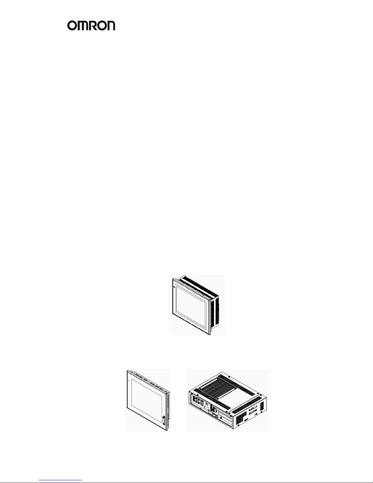
2. Hardware
We distinguish the DyaloX in two types:
• Panel Type (NSA1_-TX…_-E), available in 12 and 15 inches.
The Touch screen and CPU are integrated in one product.
• Box Type (NSA-CPU0_-E), available in 15 and 17 inches.
The Touch screen and CPU are separated from each other and connected through
USB and DVI. It is possible to mount both as one Panel computer again.
Page 7
!
3
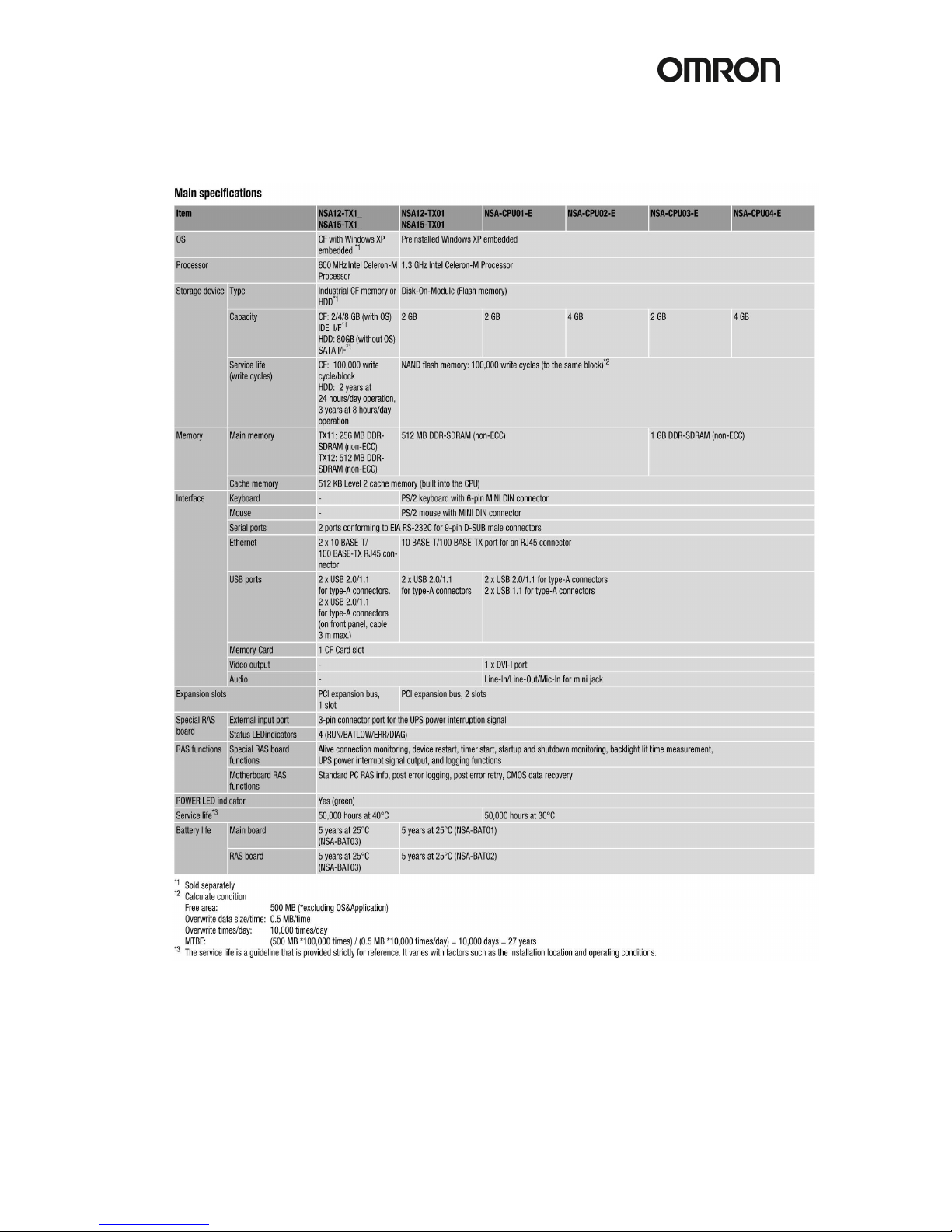
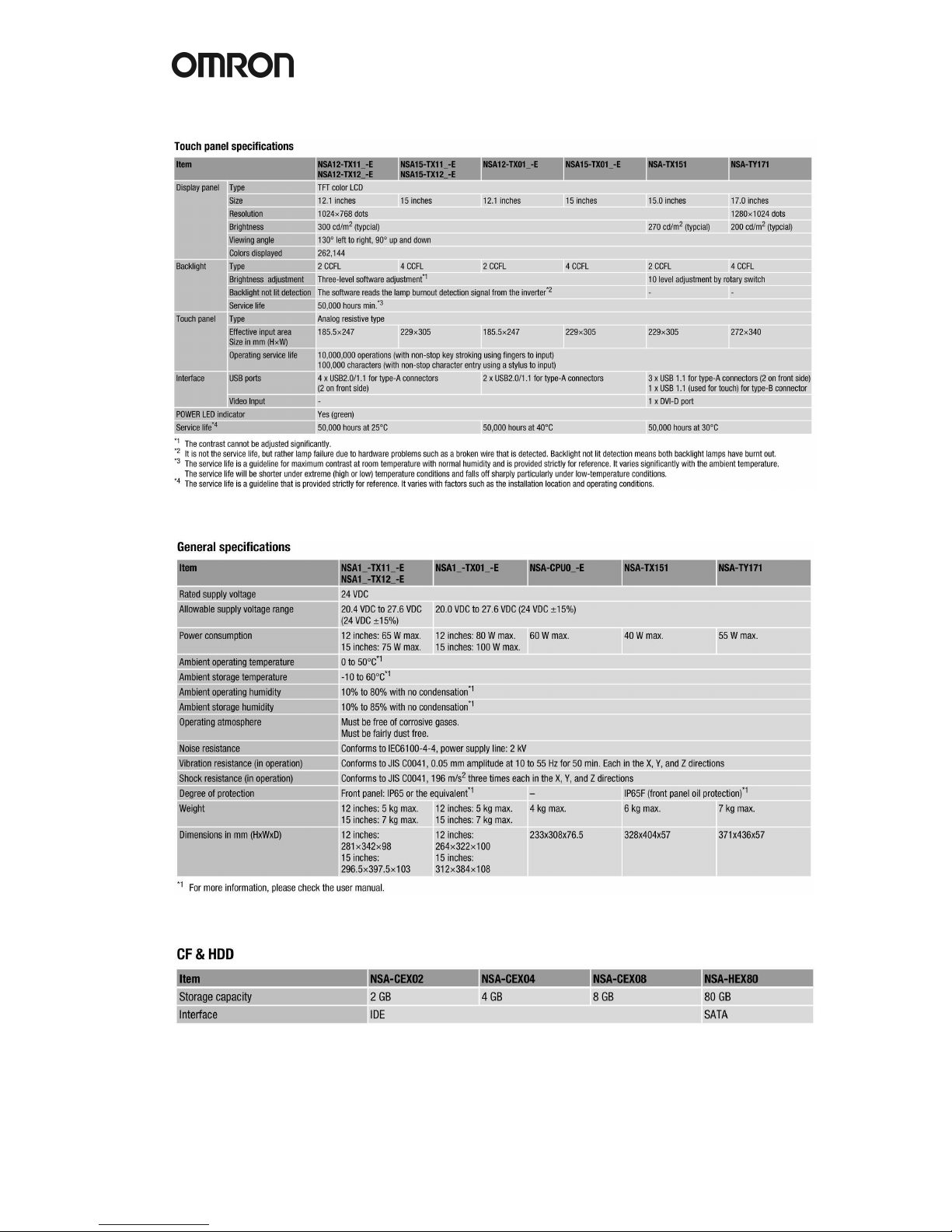
2.1 Specifications of all the DyaloX models
Page 8
4
Page 9

!
5
2.2 Communication ports
Pinning of the male RS-232C connector (COM port 1 and 2).
Pin No. Signal
1 CD Carrier Detect
2 RD Receive
3 SD Send
4 DTR Data Terminal Ready
5 GND Signal ground
6 DSR Data Set Ready
7 RTS Request To Send
8 CTS Clear To Send
9 RI Ring Indicator
Page 10
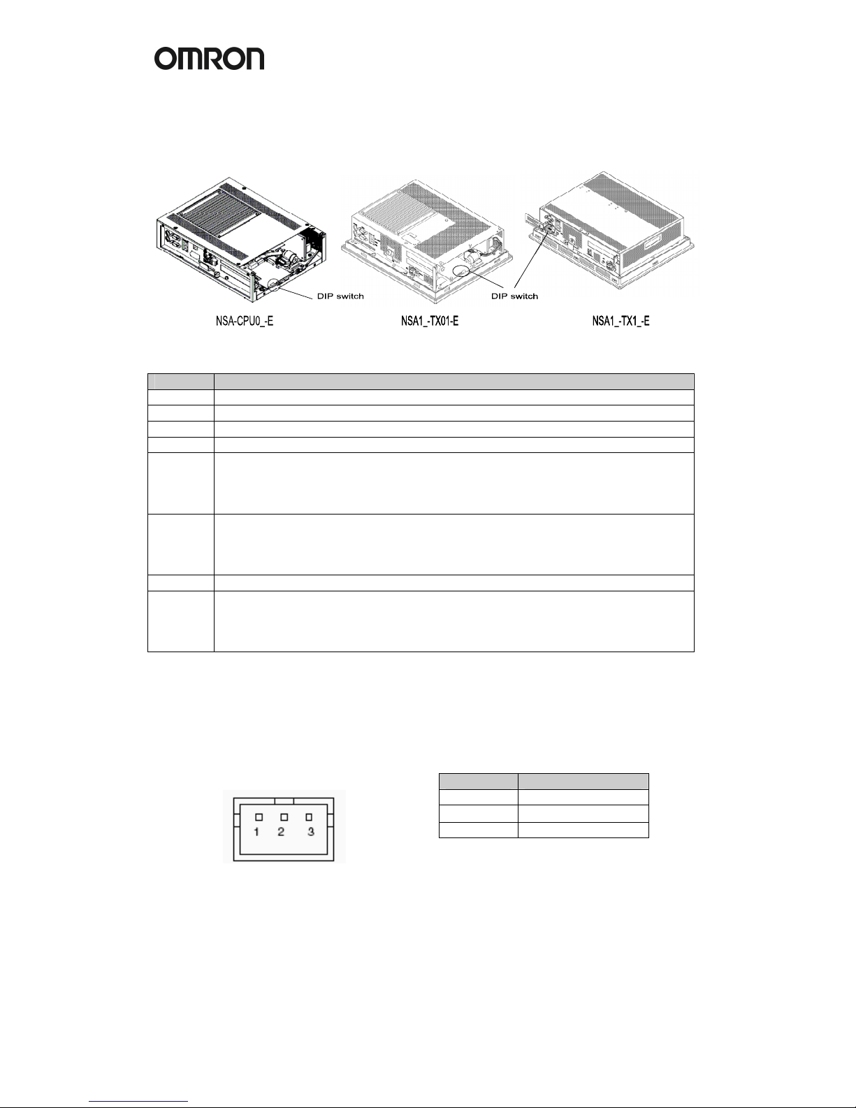
6
The following Dip Switches can be set for the DyaloX IPC.
To set the Dip Switches remove the side cover of the DyaloX IPC on the LED side.
Pin No. Function
1 Reserved [Always OFF]
2 Reserved [Always OFF]
3 Reserved [Always OFF]
4 Reserved [Always OFF]
5 Specifies the operation for the external input port on the RAS board.
ON: Connects a UPS system to the external input port.
OFF: Not connects a UPS system to the external input port. Use it as a general
Input port. [Default setting: OFF]
6 Specifies the ACFAIL signal input method for the external input port
(UPS power interrupt signal connector)
ON: Normally supplies 24V; open at PWR-FAIL
OFF: Normally open; supplies 24V at PWR-FAIL [Default setting: OFF]
7 Always OFF
8 Enables/disables actions when the RAS Board detects a
Startup/Alive/Shutdown failure.
ON: Disables the actions.
OFF: Enables the actions. [Default setting: OFF]
UPS Power Interrupt Signal Connector
This port can be used to notify the DyaloX IPC that a UPS has become active and starts to
supply the power.
Pin No. Signal
1 ACFAIL
2 NC
3 COM
Note: Set the ACFAIL input voltage to
24V ±10% (10 mA max.).
Connector: S3B-PH-K-S (JST)
Omron also supplies a backup power supply which can act as a UPS. This is the S8TS series
power supply with the S8T-DCBU-0x unit. This unit is connected to a battery pack which can
supply 24VDC for a long time.
The S8T-DCBU-0x unit has an output that can be connected to the Power Interrupt Signal
Connector of the DyaloX IPC.
Page 11

!
7
3. Software
The DyaloX IPC is installed with Microsoft® Windows XP Embedded SP2. This modular
operating system is based on Microsoft® Windows XP Professional. Omron has carefully
selected the items needed to give you flexibility to run and use many different kinds of
software, but still be able to give you the best reliable operating system for industrial use.
3.1 Bios settings
In some occasions it might be needed to change some BIOS settings. All BIOS menus are
explained in detail in the manual of the DyaloX. Below you find some basic information.
Perform the actions below to enter the BIOS setup menu.
When this message is displayed: Press <F2> to enter SETUP.
1. Press the F2 Key while the message box is displayed to launch the setup menu.
2. The Main Setting Screen will be displayed.
Note: You must enter a password if one has been set.
3. Use the Down, Left, or Right Arrow Key to go to the next item and use the Enter
Key to select the item.
Select the Exit Screen to exit from the setup menu.
Note: The RAS Board’s startup monitoring is performed (when enabled) even during BIOS
setup. Disable the Start-up monitoring function when making the BIOS settings. If the startup
monitoring function cannot be disabled, turn ON pin 8 of the DIP switch to disable the Action
on Failure function.
3.1.1 BIOS Setup Menu Keys
BIOS setup items can only be set from a keyboard. The following table lists the keys that are
available from the BIOS setup utility and how to use them.
Key Action
← → Switches menus.
↑ ↓ Selects the item that will be set.
-/+ Increases or decreases a value.
Tab Moves to the next field.
Shift + Tab Moves to the previous field.
F1 Displays the General Help Window for BIOS setup.
F9 Loads the default configuration value.
F10 Saves the settings to CMOS and exits the BIOS setup utility.
ESC Moves to the Exit Menu or moves to the Main Menu from a Submenu.
Enter Sets a value and moves to a submenu if one is available.
3.1.2 Advanced menu
In the Advanced menu there are some settings you might need or want to use.
They are explained in the table below.
Page 12

8
Function Setting Description
Legacy USB Support [Disabled] Enables or disables support for the
Enabled Legacy Universal Serial Bus.
Normally select the Disabled option.
Summary Screen Disabled Displays the System configuration when
[Enabled] Booting.
Boot-time Disabled Displays the Self-diagnosis Screen. The
Diagnostic Screen [Enabled] OMRON Logo is not displayed when
this function is enabled.
QuickBoot Mode [Disabled] Quick Boot Mode will skip certain tests
Enabled while booting. This makes booting faster.
Keyboard Features
Function Setting Description
NumLock [Auto]
On
Off
Enables the NumLock Key on the
keyboard.
Key Click [Disabled]
Enabled
Enables or disables the audible beep
when a key is pressed on the keyboard.
Keyboard auto-repeat rate [30/sec]
26.7/sec
21.8/sec
18.5/sec
13.3/sec
10/sec
6/sec
2/sec
Selects the number of times per second
to repeat a keystroke when you hold a
key down.
Keyboard auto-repeat delay 1/4 sec
[1/2 sec]
3/4 sec
1 sec
Selects the delay time after a key is held
down before it begins to repeat the
keystroke.
KBC Error [Disabled]
Enabled
Enables or disables the keyboard
connection check at startup. Normally
select the Disabled option.
Power
Function Setting Description
After Power Failure Stay OFF Selects the operation executed after
Last State A power failure.
[Power ON] Stay OFF: Always stay OFF
Last State: Return to the most recent state.
Power ON: Always stay ON
Note: Normally, select the Power ON setting because the DyaloX Industrial PC does not
have a START switch.
Boot
Function Setting Description
Priority of the Boot Removable Devices Specifies the priority in the search for
Device Hard Drive
CD-ROM Drive
a startup device.
Network Boot
Note: Press the Enter Key to show additional devices when the setting has a plus (+) sign.
Page 13

!
9
3.2 Windows XP Embedded
Windows XP Embedded for the DyaloX IPC contains the following software:
• .NET Framework 2.0
• Internet Explorer
• Visual Basic Runtime Library files v5.0 & v6.0
• C Runtime Library (4.0.1183.1)
• Remote Desktop support
Remarks on configuring Windows XP Embedded:
• The Windows firewall is enabled when the product is shipped from the factory.
Make the appropriate settings as required.
• The administrator password is not set when the product is shipped from the
factory. Set a password as required. If a password has been set, however, a
keyboard will be required when logging on.
• To use a USB-connected floppy disk drive, keyboard, or mouse when starting
Windows to update the BIOS or recover the Windows system, select Advanced
from the BIOS set-up menu and set Legacy USB Support to Enabled.
• Windows XP Embedded is an OS designed for embedded use. Some application
programs that operate on the Windows XP Professional OS may not operate on
the Windows XP Embedded OS of an DyaloX Industrial PC. In addition, the
Windows components cannot be added and deleted by selecting Add or Remove
Programs from the Control Panel.
3.3 Enhanced Write Filter (EWF)
The Enhanced Write Filter (EWF) is a special function in Windows XP Embedded that
protects a volume from write access. When you enable EWF for a certain volume you prevent
any data to be saved to the storage disk. Instead all data is saved to the RAM. This means
when you reboot the IPC the data is lost.
EWF provides the following features:
• Write protects one or more partitions on your IPC
• Keep original disk contents
• Data can be saved while EWF is disabled (commit) using EWF API
By default the EWF is disabled. You should be careful when big amount(s) of data is involved
as RAM is used to store it.
Some EWF commands you can use:
• Show EWF status: EWFMGR C:
• Enable EWF: EWFMGR C: -enable
• Write data to disk: EWFMGR C: -commit
• Help information: EWFMGR -?
More information on EWF can be found in Appendix 2 of our manual or on:
http://www.microsoft.com/embedded
Page 14

10
3.4 Available Tools
From the Start menu – All Programs – UPDD, there are several tools available.
These tools will be shortly explained here.
Universal Pointer Device Driver (UPDD) software allows you to configure pointer devices
used with the Industrial PC. Normally you will probably use the touch screen, but it is possible
to use mouse and other devices also.
Calibrate
With this tool you can calibrate the touch screen. Start the program and follow the instructions.
Event Selector
The Event Selector is a simple tool to switch the pointer from the left to the right (mouse click)
touch function. This tool can show a small window to easily use it and it can display an icon in
the toolbar.
Beside this tool there is another way to use the right mouse click, by pressing the touch area
for a defined time. Please contact your local Omron representative in case you want to use
this functionality.
Test tool
This is a simple tool to test the touch grid of the Industrial PC.
Configuration Settings
This software allows you to configure the way you want to use the pointer device on the
Industrial PC. You can also configure some display options with this tool.
On-Screen Keyboard
Windows XP Embedded provides a possibility to input alphanumeric characters from the
touch panel. It acts as a standard keyboard on the screen. To start this on-screen keyboard,
go to Start – All Programs – Accessories – Accessibility – On-Screen Keyboard.
This keyboard does not work when you need to login into Windows XP Embedded.
Page 15
!
11
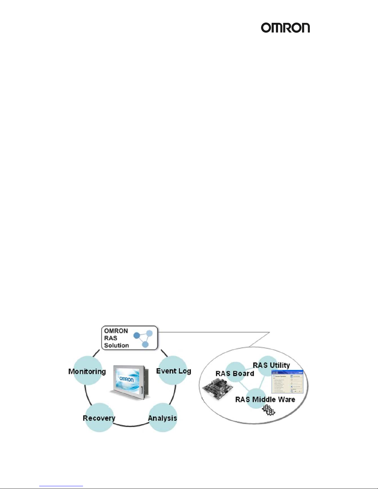
4. RAS
RAS stands for Reliability, Availability and Serviceability and is a specific OMRON designed
solution for the DyaloX to make it a true Industrial PC. Inside the DyaloX Industrial PC series,
a separate board, interfaced by embedded RAS utility software, continually monitors the
motherboard. Because this unique RAS board is a stand-alone board, it can gather data from
the motherboard no matter what the Operating System or hardware conditions of the DyaloX
are. The RAS solution can notify you when unstable hardware or software conditions are
detected. It can if needed take action to automatically resolve the failure and enables you to
investigate the causes of the failure.
Warning threshold levels can be set manually in the RAS utility. Data logged at time of failure,
such as motherboard temperatures, voltages, date and time, and other relevant data can be
uploaded from the RAS board for analysis.
So whatever the reason for failure, the RAS board is able to provide a system snapshot just
before failure occurs. By analyzing the log data, the trend and cause of failures can be quickly
found and rectified for higher reliability in the future.
The DyaloX Industrial PC series with its RAS functionality will help you achieve the highest
possible reliability in your PC Based application(s).
4.1 RAS Functions
The RAS system in OMRON Industrial PC provides the following main functions:
• Monitoring Function that constantly monitors the hardware and software of an
industrial PC and gives the user failure notification when an error is detected or a
failure occurs.
• Auto-recovery Function that forcefully shuts down the system when a failure occurs
to prevent further faults and reboot the system for recovery.
• Logging Function that saves events in operating an industrial PC (such as Power
Supply ON/OFF, OS startup/shutdown, etc.), system status when a failure occurs and
conditions of the Motherboard (temperature, power supply) onto the RAS Board's
power-backed-up memory.
• Log Analysis Function that analyzes cause and/or tendency of failures using
numerous amounts of logs saved on the memory.
Page 16

12
4.1.1 Monitoring and Auto-recovery
Monitoring Functions
The RAS functions enable users to monitor operation status and detect failures.
The DyaloX provides the following monitoring functions.
• Startup Monitoring: Provides notification of failures that occur while starting
(i.e., from turning ON the power supply until startup has been completed).
• Alive Monitoring: Provides notification of failures that occur while the OS is running
(i.e., from startup to shutdown).
• Shutdown Monitoring: Provides notification of failures that occur while shutting down
or rebooting.
• External Power Supply Under voltage/Interruption Monitoring: Detects abnormal
power interruptions for the external power supply.
• Temperature Monitoring: Detects abnormal temperatures in the Motherboard.
• Voltage Monitoring: Detects abnormal power supply voltages in the Motherboard.
• Cumulative Operating Time Monitoring: Detects excessive cumulative operating time.
• RAS Board Monitoring: Detects failures with the RAS Board.
• LCD Monitoring: Detects failures with the LCD.
Action on Failures (forced shut down/forced reboot)
RAS can take action where a failure is detected. The following functions are provided:
• Rebooting the system automatically when the operating system freezes
• Starting the system and restoring operation automatically after the Motherboard
stops because of a failure, such as overheating
• Repeating reboot attempts automatically until the system is successfully activated, if
the system hangs-up at startup
• Forcefully terminating the system automatically when the system takes too much
time to shut down.
Failure Notification
The Failure Notification function reports a failure when it occurs or after the system recovers
from the failure. It notifies the user of a failure with a pop-up message that allows the user to
immediately identify the situation.
• The user is notified of power failure that causes shutdown of the system.
• When the system goes down due to some failure, this function notifies the user of the
nature of the failure and the status of the Industrial PC after the system recovers from
the failure.
• The user is immediately notified of any abnormal temperature or voltage in the
Motherboard.
• The user is notified that LCD Backlight lifetime is nearing its limit.
Page 17

!
13
4.1.2 Logging Function and Log Analysis Function
The system keeps a log of operational events as well as of the status of the Industrial PC
(temperature, voltage, etc.) in memory. The logs are saved in the RAS Board memory even if
the Industrial PC cannot start due to a failure, so the user can analyze the log based on the
information stored in the RAS memory in order to identify the cause of the failure. The RAS
Utility includes Filter and Find functions to analyze logs.
These functions allow the user to analyze the logs more effectively by specifying events in a
particular period or classifying events in categories.
The RAS Utility allows the user to import/export log files. The user may export log files to save
logs to a file on a regular basis. The user may also import log files to compare and analyze
past logs with logs currently in the memory or to conduct log analysis on another PC.
4.2 RAS Utility software
The RAS utility software is the GUI to the RAS system. This software informs the user of
failures, warnings, and statuses and also allows the user to configure RAS.
The RAS utility is started when the users logs in on Windows. The small icon shown in the
picture below (icon in red square) shows this.
This icon shows the present status of the RAS. With the RAS utility you can also disable the
notification of failures.
Icon Status
The Failure Notification is enabled.
The Failure Notification is disabled.
When you click on the RAS icon it will present you a small popup menu.
If you choose “Open” from the menu the main window of the RAS utility will be shown.
Page 18

14
The Main window of RAS has two areas, namely the Status information area and the
Operation menu.
Status Information
Status Description
No Failures are detected by RAS.
A failure was detected.
Open the Detail Window to identify the failure.
RAS Utility cannot communicate with the RAS Board. Check
the status of the RAS service (OMRON RAS Scheduler).
Note: You can check the status of the RAS service by [Control Panel] - [Administrative Tools]
- [Services].
The following Failures are detected and notified by RAS
Report Description
Monitoring: Failure-detected A Monitoring failure is detected.
Error: LCD Backlight The LCD backlight has a failure.
Warning: Temperatures The temperatures of the Motherboard exceed the
threshold.
Warning: Voltages The voltages of the motherboard exceed the threshold.
Warning: Accumulated Hours The accumulated hours exceed the threshold.
Error: Startup Monitoring A Startup failure was detected.
Error: Alive Monitoring An Alive failure was detected.
Error: Shutdown Monitoring A Shutdown failure was detected.
Error: Power Failure A Power failure was detected.
Error: RAS Board The RAS Board has a failure.
Error: RAS Board Battery The battery on the RAS Board is low or disconnected.
Error: UPS PF Signal-detected The UPS Power Failure signal was detected.
Page 19
!
15
Operation menu
Button Description
View more detail Displays the Detail window.
Shutdown OS Shuts down the operating system.
Restart OS Restarts the operating system.
Close this window Closes this Main window.
Failure Notification: ON Enables the Failure Notification. The Main window
automatically pops up when a failure is detected.
Failure Notification: OFF Disables the Failure Notification. The Main window does not
automatically appear even when a failure is detected.
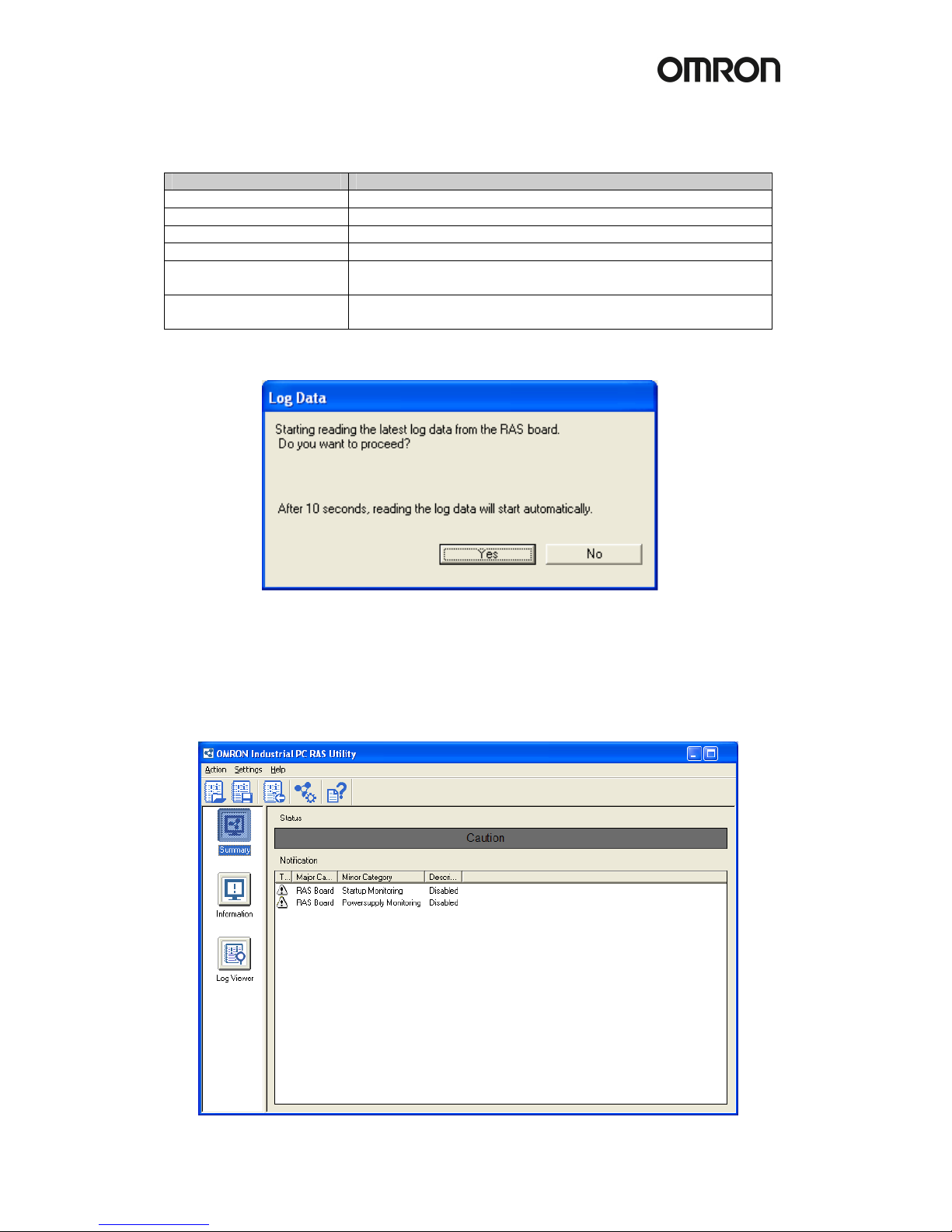
When you choose “View more detail” in the menu, you will see the following popup window:
Choose “Yes” to upload the latest log file from the RAS board. This will take 1 or 2 minutes.
Choose “No” if you do not want to look at the log files. You can always upload them at a later
time. The Summary information window is now displayed. From this window you have access
to all the functions of RAS.
Summary window
Page 20

16
The Summary information window shows the status of RAS and the information why this
status is shown. RAS can show the following statuses in this window:
Status Color Description
Normal Green Shows the RAS status is normal.
Caution Yellow Shows the RAS detected a recoverable error or some monitoring
functions are disabled.
Warning Orange Shows the RAS detected an error to be recovered by an operator.
Failure Red Shows the RAS detected a serious error such as an Alive Error.
Note: You can change a message of the RAS status in [RAS Utility Settings] - [Others].
RAS Utility Toolbar buttons
Icon
Name
Description
Open Log File Opens a log data file and displays the contents in the Log Viewer.
Save Log File Saves the log data displayed in the Log Viewer to a file.
Read Latest Log
Data
Reads the latest log data from the RAS Board and displays the
log data in the Log Viewer.
RAS Settings Displays the RAS Settings.
Help
Displays the RAS Utility Help.
Information window
The information window will show specific information for each of the following areas:
• Accumulated Hours
• Detected Errors
• RAS Board
• Motherboard
• LCD
Page 21

!
17
Log Viewer window
After you uploaded the log files from the RAS board you can view those log files here.
This window allows you to filter all the log files and even find a specific error in the files.
Beside the RAS log files it also allows you to view the Windows Event log files that are logged
on the D:\ partition.
Page 22
18
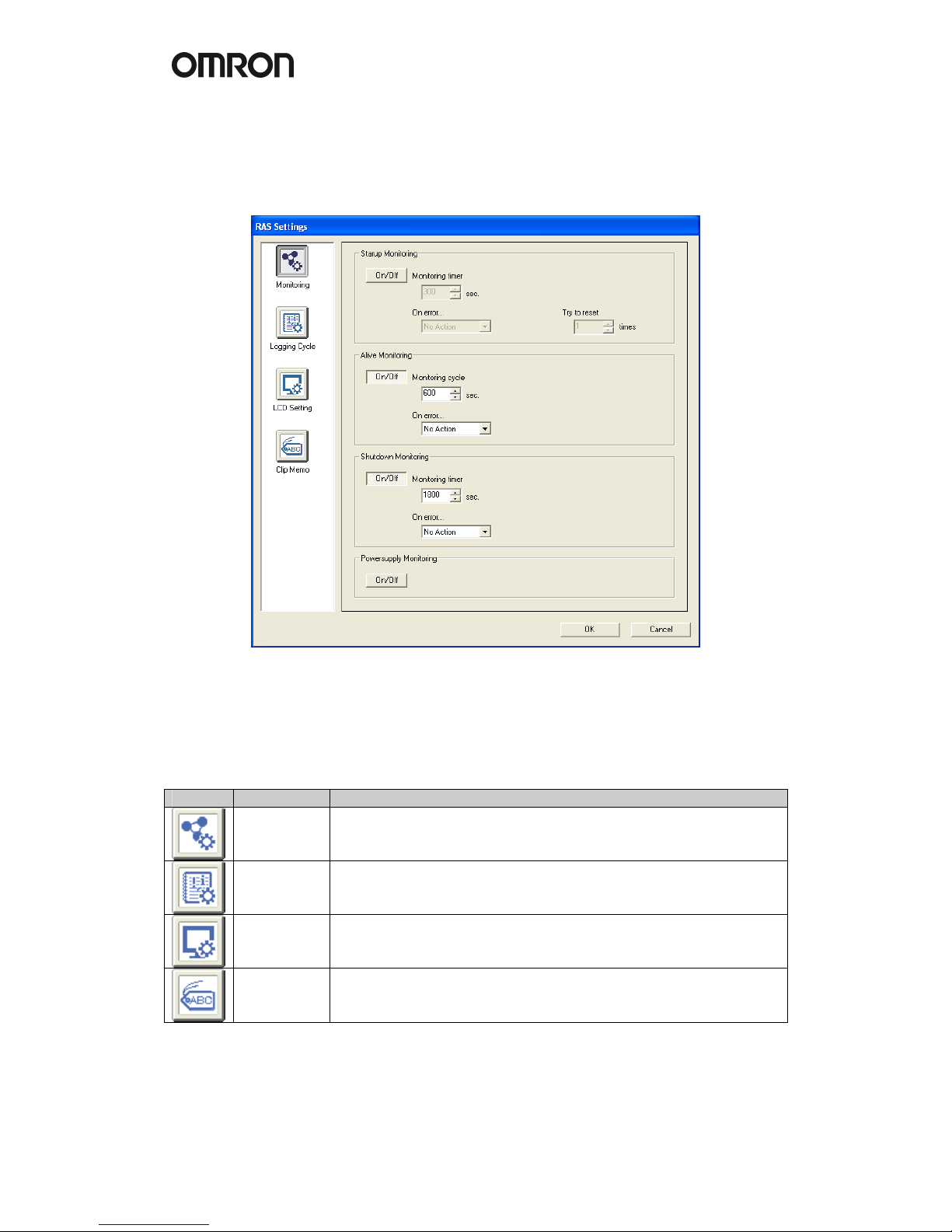
4.2.1 RAS Settings
To change the default behavior of RAS, you have to change some settings as explained here.
In the RAS utility go to the “Settings” menu and choose “RAS Settings”.
The following window appears:
Click an icon in the list to show the specific page.
Icon Page Description
Monitoring To configure the Startup/Alive/Shutdown Monitoring.
Logging
Cycle
To configure the Logging Cycle to acquire voltages/temperature
information from the Motherboard.
LCD Setting To configure the LCD Setting.
Clip Memo To configure the Clip Memo to store memo’s in the RAS Board.
For each page the settings are explained below.
Page 23

!
19
Monitoring
Function Item Description
All On/Off
Enables/disables the function.
Startup
Monitoring
timer
Specifies a monitoring time for startup.
If the startup process was not completed within the specified
period, the RAS Board detected a Startup failure.
No
Action
No action when a Startup failure occurs.
Reset The RAS Board forces the Motherboard to reset on a
Startup failure.
If the next startup process was not completed within the
specified period again, the trial repeats up to a specified
number of times in [Try to restart].
On error...
Power
OFF
The RAS Board forces the Motherboard to Power Off
when a Startup failure occurs.
Try to reset
Specifies a number of times to repeat the restart cycle.
Alive
Monitoring
Cycle
Specifies monitoring intervals for the Alive check.
If the RAS service does not respond within the specified period,
the RAS Board detected an Alive Failure.
No
Action
No action when the Alive failure occurs.
Reset The RAS Board forces the Motherboard to reset when
an Alive failure occurs.
On error...
Power
OFF
The RAS Board forces the Motherboard to Power Off
when an Alive failure occurs.
Shutdown
Monitoring
timer
Specifies a monitoring time for Shutdown.
If the shutdown process was not completed within the specified
period, the RAS Board detected a Shutdown Failure.
No
Action
No action when the Shutdown failure occurs.
Reset The RAS Board forces the Motherboard to reset when a
Shutdown failure occurs.
On error...
Power
OFF
The RAS Board forces the Motherboard to Power Off
when a Shutdown Failure occurs.
Note: The Startup Monitoring is active even during the BIOS setup! Therefore, disable the
Startup Monitoring to configure the BIOS settings. With Dip Switch pin no. 8 on the RAS
Board you can disable RAS monitoring functions.
Logging Cycle
Here you configure the logging cycle of the RAS board.
Item Description
On/Off Enables/disables the RAS logging.
starts Specifies a time after the IPC startup for the Initial logging.
at intervals of Specifies intervals for the periodic logging.
LCD Setting
Item Description
ON/Off Enables/disables the LCD Backlight monitoring.
LCD Backlight
Brightness
Selects a level of the LCD backlight brightness among from High, Middle
and Low. Default is High.
Note: For NSA-CPU0x-E models the LCD Backlight monitoring is not supported.
Page 24

20
Clip Memo
Here you can store short memos in the RAS Board for maintenance reasons.
Item Description Example
Clip Memo A Any text up to 20 characters Last Update
Clip Memo B Any text up to 20 characters RAS Setting
Clip Memo C Any text up to 20 characters 22-02-2006
Clip Memo D Any text up to 20 characters Battery
Clip Memo E Any text up to 20 characters 03-03-2006
Beside the RAS settings there are also some RAS Utility settings. In the RAS Utility settings
you can configure the Thresholds and UPS settings. The RAS Utility settings can be found
from the “Settings” menu by choosing “RAS Utility Settings”.
Click an icon in the list to show the specific page.
Icon
Page
Description
Thresholds
To tune the Thresholds for the Accumulated Hours, Voltages and
Temperatures of the Motherboard.
UPS
To configure settings at the time of the Power Failure Signal
detection from the UPS.
Others To configure messages for errors and the status refresh cycle.
For the Threshold settings please check the online help file of the RAS Utility.
The UPS settings are explained below.
Item Description
On/Off Enables/disables the UPS Power Failure Signal monitoring.
UPS PF Signal
Detection Cycle
Specifies a monitoring time for UPS Power Failure Signal. Every cycle
RAS will detect the input in the RAS board.
No
Action
No action when the UPS Power Failure Signal is detected.
On Signal
detected
Shutdo
wn
RAS Utility executes OS shutdown when the Power Failure
Signal is detected.
Wait time from on
PF Signal detected
The time RAS waits until it shuts down the DyaloX after detecting a PF
signal. Normally this time is set according to the battery capacity of the
UPS and the time needed to safely close the applications currently
running on the DyaloX.
Page 25

!
21
4.2.2 Clear Failure(s)
Most failures will automatically be removed from the Main RAS window, however some
monitoring failures will remain visible even if the original failure has been resolved already.
You can manually clear the RAS errors when the failure itself has been resolved.
To do this, follow the instructions below.
1. Click “Clear Failure-detected Mode” in “Action” menu.
2. The following confirmation dialog box appears:
3. Click the “OK” button to clear the Failure(s) detected.
4. You can confirm the current monitoring status in the Main window or
Summary/Information window.
5. Restore image with USB stick
In the same box where you found this manual, you will also find a USB stick.
This USB stick acts like a Startup disk so that you can boot the DyaloX IPC with this USB
stick. For this it is necessary that you configure in the BIOS to boot from the USB stick first
else it will just boot from the default disk.
To do this, follow the steps below:
1. Boot the DyaloX IPC
2. When you see the message “Press <F2> to enter SETUP”, press F2
3. Select the “Boot” menu
4. Select “Hard Drive” and press Enter
5. Now you see a list of drives. In this list you should also see the SanDisk USB stick.
Select the SanDisk entry and move the SanDisk drive above the InnoDisk drive by
pressing the plus (+) key.
6. Select the “Exit” menu and choose “Exit Saving Changes”. Confirm saving changes.
7. The DyaloX IPC will now reboot and show the Windows Startup Menu.
The USB stick contains some Windows startup files and a free tool to restore and save a disk
image. This tool is provided free of charge and Omron is not liable for any damaged caused
by using this tool. It is advised that when you need more than this basic functionality, that you
buy a commercial imaging tool, like Acronis or Norton Ghost.
From the Microsoft Windows Startup Menu you can choose to save or restore a disk image.
See the About option for more information about the tool.
The image file that will be restored is located on the USB stick and when you create an image
it will also be saved to the USB stick by default. It is advised that you create a backup of this
USB stick.
 Loading...