

Page 1

USER’S MANUAL
NSA-Series Industrial PC
NSA12/15-TX01B
NSA12/15-TX01S
NSA12/15-TX01B-E
NSA12/15-TX01S-E
Cat. No. V233-E1-03
Page 2

Page 3

NSA Series Industrial PC
NSA12/15-TX01B
NSA12/15-TX01S
NSA12/15-TX01B-E
NSA12/15-TX01S-E
User's Manual
Page 4

iv
Page 5

Introduction
f
The NSA-series Industrial PC is an industrial, panel-mountable computer equipped
with a Celeron M Processor and featuring a touch panel and display.
Be sure to read and understand the functions and performance specifications in
this manual prior to using it, and operate it as described herein.
Intended Audience
This manual is intended for the following personnel, who must also have
knowledge of electrical systems (an electrical engineer or the equivalent).
· Personnel in charge of introducing FA systems into production facilities
· Personnel in charge of designing FA systems
· Personnel in charge of managing FA systems and facilities
Notice
This manual provides information for connecting and setting up an NSA-series
Industrial PC. Be sure to read this manual before attempting to use it, and keep the
manual close at hand for reference during operation.
OMRON, 2006
All rights reserved. No part of this publication may be reproduced, stored in a retrieval system, or transmitted, in any form, or
by any means, mechanical, electronic, photocopying, recording, or otherwise, without the prior written permission o
OMRON.
No patent liability is assumed with respect to the use of the information contained herein. Moreover, because OMRON is constantly striving to improve its high-quality products, the information contained in this manual is subject to change without
notice. Every precaution has been taken in the preparation of this manual. Nevertheless, OMRON assumes no responsibility
for errors or omissions. Neither is any liability assumed for damages resulting from the use of the information contained in
this publication.
v
Page 6

vi
Page 7

Read and Understand this Manual
Please read and understand this manual before using the product. Please consult your OMRON
representative if you have any questions or comment s.
Warranty and Limitations of Liability
WARRANTY
OMRON's exclusive warranty is that the products are free from defects in materi als and workmanship for a
period of one year (or other period if specified) from date of sale by OMRON.
OMRON MAKES NO WARRANTY OR REPRESENTATION, EXPRESS OR IMPLIED, REGARDING
NON-INFRINGEMENT, MERCHANTABILITY, OR FITNESS FOR PARTICULAR PURPOSE OF THE
PRODUCTS. ANY BUYER OR USER ACKNOWLEDGES THAT THE BUYER OR USER ALONE HAS
DETERMINED THAT THE PRODUCTS WILL SUITABLY MEET THE REQUIREMENTS OF THEIR
INTENDED USE. OMRON DISCLAIMS ALL OTHER WARRANTIES, EXPRESS OR IMPLIED.
LIMITATIONS OF LIABILITY
OMRON SHALL NOT BE RESPONSIBLE FOR SPECIAL, INDIRECT, OR CONSEQUENTIAL DAMAGES,
LOSS OF PROFITS OR COMMERCIAL LOSS IN ANY WAY CONNECTED WITH THE PRODUCTS,
WHETHER SUCH CLAIM IS BASED ON CONTRACT, WARRANTY, NEGLIGENCE, OR STRICT
LIABILITY.
In no event shall the responsibility of OMRON for any act exceed the individual price of the product on
which liability is asserted.
IN NO EVENT SHALL OMRON BE RESPONSIBLE FOR WARRANTY, REPAIR, OR OTHER CLAIMS
REGARDING THE PRODUCTS UNLESS OMRON'S ANALYSIS CONFIRMS THAT THE P RODUCTS
WERE PROPERLY HANDLED, STORED, INSTALLED, AND MAINTAINED AND NOT SUBJECT TO
CONTAMINATION, ABUSE, MISUSE, OR INAPPROPRIATE MODIFICATION OR REPAIR.
vii
Page 8

Application Considerations
SUITABILITY FOR USE
OMRON shall not be responsible for conformity with any standards, codes, or regulations that apply to the
combination of products in the customer's application or use of the products.
At the customer's request, OMRON will provide applicable third party certification documents identifying
ratings and limitations of use that apply to the products. This information by itself is not sufficient for a
complete determination of the suitability of the products in combination with the end product, machine,
system, or other application or use.
The following are some examples of applications for which particular attention must be given. This is not
intended to be an exhaustive list of all possible uses of the products, nor is it intended to imply that the uses
listed may be suitable for the products:
• Outdoor use, uses involving potential chemical contamination or electrical interference, or conditions or
uses not described in this manual.
• Nuclear energy control systems, combustion systems, railroad systems, aviation systems, medical
equipment, amusement machines, vehicles, safety equipment, and installations subject to separate
industry or government regulations.
• Systems, machines, and equipment that could present a risk to life or property.
Please know and observe all prohibitions of use applicable to the products.
NEVER USE THE PRODUCTS FOR AN APPLICATION INVOLVING SERIOUS RISK TO LIFE OR
PROPERTY WITHOUT ENSURING THAT THE SYSTEM AS A WHOLE HAS BEEN DESIGNED TO
ADDRESS THE RISKS, AND THAT THE OMRON PRODUCTS ARE PROPERLY RATED AND
INSTALLED FOR THE INTENDED USE WITHIN THE OVERALL EQUIPMENT OR SYSTEM.
PROGRAMMABLE PRODUCTS
OMRON shall not be responsible for the user's programming of a programmable pro duct, or any
consequence thereof.
viii
Page 9

Disclaimers
CHANGE IN SPECIFICATIONS
Product specifications and accessories may be changed at any time based on improvements and other
reasons.
It is our practice to change model numbers when published ratings or features are changed, or when
significant construction changes are made. However, some specifications of the prod ucts may be changed
without any notice. When in doubt, special model numbers may be assigned to fix or establish key
specifications for your application on your request. Please consult with your OMRON representative at any
time to confirm actual specifications of purchased products.
DIMENSIONS AND WEIGHTS
Dimensions and weights are nominal and are not to be used for manufacturin g p urposes, even when
tolerances are shown.
PERFORMANCE DATA
Performance data given in this manual is provided as a guide for the user in determining suitability and does
not constitute a warranty. It may represent the result of OMRON's test conditions, and the users must
correlate it to actual application requirements. Actual performance is subject to the OMRON Warranty and
Limitations of Liability.
ERRORS AND OMISSIONS
The information in this manual has been carefully checked and is belie ved to be accurate; however, no
responsibility is assumed for clerical, typograp hical, or proofreading errors, or omissions.
ix
Page 10

Safety Precautions
Safety-related Indications and Their Meanings
The following precautionary indications and symbols are used in this manual to aid
in the safe usage of the NSA-series Industrial PC. These precautions contain
important safety information. Be sure to observe them carefully.
The indications and symbols used herein, and their meanings, are as listed below.
Indicates a potentially hazardous situation which, if not avoided,
! WARNING
! Caution
Precautions for Safe Use
Indicates actions that should be done, or avoided, for the safe use of this product.
Precautions for Correct Use
Indicates actions that should be done, or avoided, to prevent operating failure or
malfunction of this product, or to prevent adverse effects on the performance or
functions of this product.
Note
Notes within the text of this manual indicate safety-related points and information
that are equivalent in importance to those included in the Precautions for Safe Use
sections.
could result in death or serious injury. Additionally, there may be
severe property damage.
Indicates a potentially hazardous situation which, if not avoided,
may result in minor or moderate injury, or property damage.
!WARNING Failure to read and understand the information provided in this manual may result in per-
sonal injury or death, damage to the product, or product failure. Please read each section
in its entirety and be sure you understand the information provided in the section and
related sections before attempting any of the procedures or operations given.
x
Page 11
Symbols
Electrical Shock Caution
Indicates possibility of electric shock under
specific conditions.
General Prohibition
Indicates non-specific general prohibitions.
Disassembly Prohibition
Indicates prohibitions when there is a possibility
of injury, such as from electric shock, as the
result of disassembly.
Mandatory Action
Indicates a mandatory action with the specific
contents indicated in the circle and described in
the text.
General Caution
Indicates non-specific general cautions,
warnings, and dangers.
xi
Page 12
WARNING
Be sure to observe all warning instructions while using this product.
Do not scratch the power supply connection cable.
Do not scratch or forcefully bend the power supply connection cable. Doing so may
damage the cable and may cause electric shock or fire.
Do not disassemble or modify the product.
Do not disassemble, cut, modify, or burn the product, and do not touch internal
parts while the power is ON. Doing so may cause electric shock or fire.
Do not splash with water.
• Do not use the product in a location where it might be splashed with water, or in
any location near water. Water contacting electr ical components may cause
electric shock, ground fault, or short-circuiting, which may result in fire.
• If a beverage or other liquid is spilled onto the product, turn OFF the power
immediately, and remove all connectors from the power supply input terminal
block.
Do not touch the power supply input terminals with wet hands.
Doing so may cause electric shock or other injury.
If smoke or an abnormal odor or sound is generated, turn OFF the power
immediately, and disconnect the power supply input connector.
Using the product in this condition may cause short-circuiting, which may result in
fire or electric shock.
If the product is knocked over or is subject to a strong impact, turn OFF the power
immediately, and disconnect the power supply input connector.
Using the product in this condition may cause short-circuiting, which may result in
fire or electric shock.
Ground the product.
A functional terminal is provided for grounding. If the product is not grounded and a
ground fault occurs, it may result in fire or electric shock.
xii
Page 13
Caution
Hold the connector housing when disconnecting the power connection cable.
Hold the connector housing, rather than the cable, when disconnecting the cable.
Pulling the cable may break wires inside, which may result in heating or fire.
Observe all relevant standards and environmental conditions.
Observe all standards for power supply voltage, frequency, capacity, etc. Using the
product under conditions not prescribed by these standards may cause electric shock
or fire.
Do not place objects on top of the product.
Do not place objects on top of the product or press on the product. Doing so may
damage the product and result in injury.
Do not place objects near the ventilation holes.
Do not place objects near the ventilation holes, or block the holes in any way. Doing so
may cause the product to malfunction.
Do not tip the product over or strike it with anything.
Do not subject the product to vibration or impacts, particularly when the power is ON. If
the product is subjected to impacts by being dropped or struck, it may fail to operate
correctly.
Do not use or store the product in the following locations.
Using or storing the product in any of the following locations may cause electric shock,
fire, or malfunction.
• Locations that are unstable or subject to vibration
• Locations subject to static electricity
• Locations subject to dust or high humidity
• Locations subject to direct sunlight
• Locations subject to flames or heat accumulation
• Locations subject to exposure to chemicals
• Locations close to heating or cooling equipment
• Locations subject to water seepage
• Locations subject to ground faults
Do not use the product near a radio, television, or cordless telephone. Doing so may
cause electrical noise to enter the product or the radio, television, or cordless
telephone, preventing correct operation.
Do not allow condensation to form on or in the product.
Installing the product in a location with high humidity, or installing the product indoors
soon after bringing it in from the outdoor cold may cause condensation to form on or in
the product, and using the product in this condition may cause malfunction.
Dispose of the product and batteries correctly.
The product contains lithium batteries. Dispose of the product and batteries according
to local ordinances as they apply. Have qualified specialists properly dispose of used
batteries as industrial waste.
Provide sufficient working space.
Prior to moving the product or replacing components, ensure that there is sufficient
room and no interfering obstacles.
xiii
Page 14

Turn OFF the power supply before doing any work on the product.
Do not touch the product case or the heat dissipation panel on the rear surface of the
case while the power supply is turned ON because they become very hot.
Also, turn OFF the power and wait for the product to cool down before doing any
maintenance work on the product.
When turning OFF the power supply, either tur n O FF the external input power supply
or disconnect the power supply input connector.
The NSA-series Industrial PC must be installed within a control panel.
Use a control panel that meets or exceeds Type 1 enclosure standards.
Maintain appropriate environmental conditions.
Use the NSA-series Industrial PC in an environment with a pollution degree of 2 or
better.
Do not connect the NSA-series Industrial PC directly to a commercial power supply.
Supply power through an isolation transformer with a capacity of 200 VA max.
xiv
Page 15

Precautions for Safe Use
Observe the following precautions when using the NSA-series Industrial PC.
1. When unpacking the product, check carefully for any external scratches or other
damage. Also, shake the product gently and check for any abnor m al sound.
2. The mounting panel must be between 1.6 and 4.0 mm thick.
3. Tighten the Mounting Brac k ets evenly to a torque of between 0.5 and 0.6 N·m to
maintain water and dust resistance. Make sure the panel is not dirty or warp ed
and that it is strong enough to hold the product.
4. Do not let metal particles enter the product when preparing the panel.
5. Do not connect an AC power supply to the power terminals.
6. Do not perform a dielectric voltage test.
7. Use a DC power supply with reinforced insulation and minimal voltage
fluctuation.
Rated power supply voltage: 24 VDC (Allowable range: 20.4 to 27.6 VDC),
Capacity: 80 W min.
8. Connect to the power supply terminal block using a twisted-pair cable with
copper wire between AWG16 and AWG12 with a minimum temperature rating of
75°C. Tighten the terminal screws to a torque of 0.5 to 0.6 N·m (5 to 7 lb·in). Be
sure the screws are properly tightened.
9. Turn OFF the power supply before connecting or disconnecting cables.
10. Always tighten the connector screws after connecting communications cables.
11. The maximum tensile load for cables is 30 N. Do not apply loads greater than
this.
12. Confirm the safety of the system before turning ON or OFF the power supply.
13. Always reset the power supply after changing switch settings.
14. Do not perform the following operations while the Memory Card is being
accessed:
· Turning OFF the power supply to the
· Removing the Memory Card
Always follow the specified procedure when removing the Memory Card.
15. Do not press the touch switch with a force greater than 30 N.
16. Do not accidentally press touch switch when the backlight is not lit or when the
display does not appear. Confirm the safety of the system before pressing touch
panels.
17. Do not attempt to disassemble, repair, or modify the product in any way.
18. Dispose of any battery that has been dropped on the floor or otherwise
subjected to excessive shock, as this may cause the battery fluid to leak.
19.Dispose of the product and batteries according to local ordinances as they apply .
Have qualified specialists properly dispose of used batteries as industrial waste.
NSA-series Industrial PC.
xv
Page 16

20.Do not connect a USB connector to any device that is not applicable.
21. Before connecting a USB connector to a device, make sure that the device is
free of damage.
22. When mounting the Battery, be sure to use the correct Battery and mount it
correctly.
23. The backlight in the NSA-series Industrial PC contains mercury. Do not dispose
of the NSA-series Industrial PC together with other waste to be sent to a
disposal site. Dispose of the NSA-series Industrial PC according to local
ordinances as they apply.
24. Use a PCI Board that complies with the EMC Directive. If a PCI Board that does
not comply with the EMC Directive is used, there are certain measures that the
user must take.
25. Use only a CF (Compact Flash) Card that has CE Markings.
26. Thoroughly test any application programs created by users or third-party
vendors to confirm that they operate properly before actually using them with
the product.
27. OMRON cannot assume any responsibility for programs created by any party
other than OMRON, nor for the results of using such programs.
28. Windows XP Embedded is an OS designed for embedded use. Some
application programs that operate on the Windows XP Professional OS may not
operate on the Windows XP Embedded OS of an NSA-series Industrial PC. In
addition, the Windows components cannot be added and deleted by selecting
Add or Remove Programs from the Control Panel.
xvi
Page 17

Precautions for Correct Use
Install the NSA-series Industrial PC correctly, as described in this manual.
● Do not install the Unit in the following places:
· Locations subject to direct sunlight
· Locations subject to temperatures or humidity outside the range specified in
the specifications
· Locations subject to condensation as the result of severe changes in
temperature
· Locations subject to corrosive or flammable gases
· Locations subject to dust (especially iron dust) or salts
· Locations subject to exposure to water, oil, or chemicals
· Locations subject to shock or vibration
● Take appropriate and sufficient countermeasures when installing systems in the
following locations:
· Locations subject to static electricity or other forms of noise
· Locations subject to strong electromagnetic fields
· Locations subject to possible exposure to radioactivity
· Locations close to power supplies
xvii
Page 18
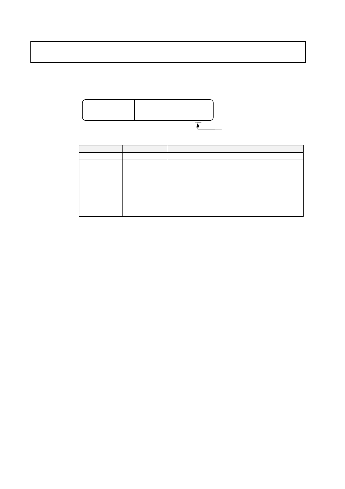
Revision History
A manual revision code appears as a suffix to the catalog number on the front
cover of the manual.
Cat. No.
V233-E1
-03
Revision Code
Revision code Date Revision content
01 January 2006 Original production
02 September 2006 Added information on the NSA12-TX01S(-E) Toolbar Model
and 15-inch Models NSA15-TX01B(-E) and
NSA15-TX01S(-E).
• Added descriptions of the RAS Utility functions .
• Added precautions.
03 January 2007 Page 1-3: Changed capacity and service life specifications.
Page Appendix-23: Changed the writing lifetime from
300,000 cycles to 100,000 cycles.
xviii
Page 19
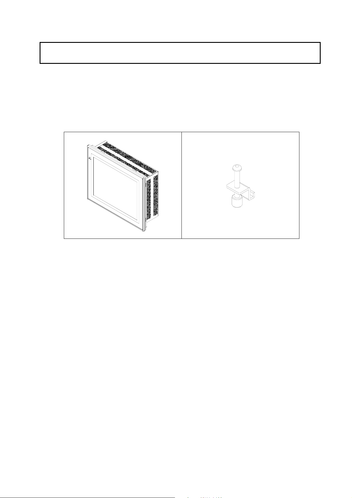
Checking the Contents of the Package
The NSA-series Industrial PC is shipped together with a number of accessories.
When opening the package, make sure that all of the parts shown below are
included and in good condition.
In the event that any of these parts is missing or damaged, contact the sales
representative from whom you purchased the product.
Main Body Mounting Brackets (8)
OS (Operating System) License
Instruction Sheet
xix
Page 20

xx
Page 21

Section 1 Overview and Specifications
1
Section 2 Nomenclature
Section 3 Installing the NSA-series Industrial PC and
Connecting Peripheral Devices
Section 4 RAS Functions
Section 5 Maintenance
Appendix
2
3
4
5
Appendix
xxi
Page 22

Table of Contents
Introduction.....................................................................................................................v
Intended Audience...............................................................................................................v
Notice ...............................................................................................................................v
Safety Precautions .........................................................................................................x
Safety-related Indications and Their Meanings ...................................................................x
Precautions for Safe Use..............................................................................................xv
Precautions for Correct Use.......................................................................................xvii
Revision History......................................................................................................... xviii
Checking the Contents of the Package.......................................................................xix
Table of Contents....................................................................................................... xxii
Section 1 Overview and Specifications
1-1 Overview..........................................................................................................1-2
1-1-1 Overview............................................................................................................ 1-2
1-1-2 Features............................................................................................................. 1-2
1-2 Specifications...................................................................................................1-3
1-2-1 Ratings and Specifications ................................................................................ 1-3
1-2-2 General Specifications....................................................................................... 1-4
1-2-3 Dimensions and External Appearance.............................................................. 1-7
Section 2 Nomenclature
2-1 Nomenclature ..................................................................................................2-2
2-1-1 Front Panel ........................................................................................................ 2-2
2-1-2 Rear Panel......................................................................................................... 2-2
2-1-3 Connectors and Interfaces................................................................................. 2-3
Section 3 Installing the NSA-series Industrial PC and Connecting Peripheral
Devices
3-1 Basic Operating Procedures............................................................................ 3-2
3-2 Installing a PCI Board and Setting the DIP Switch.......................................... 3-4
3-3 Installing the NSA-series Industrial PC............................................................ 3-9
3-3-1 Environment....................................................................................................... 3-9
3-3-2 Installing the NSA-series Industrial PC in a Control Panel.............................. 3-10
3-3-3 Connecting the Power Supply ......................................................................... 3-11
3-3-4 Connecting the Grounding Wire ...................................................................... 3-12
3-4 Starting the Industrial PC and Procedure after Power Interruption...............3-14
3-4-1 Operation.........................................................................................................3-14
xxii
Page 23

3-4-2 Operating Sequence for the External Power Supply....................................... 3-15
3-4-3 Installation Procedure...................................................................................... 3-16
3-4-4 Removal Procedure......................................................................................... 3-17
3-5 Adjusting the Touch Panel and Display.........................................................3-18
3-5-1 Calibrating the Touch Panel............................................................................ 3-18
Section 4 RAS Functions
4-1 RAS Function Details.......................................................................................4-2
4-1-1 What Is the RAS Solution for OMRON Industrial PCs ?................................... 4-2
4-1-2 Monitoring and Auto-recovery ........................................................................... 4-2
4-1-3 Logging Function and Log Analysis Function.................................................... 4-3
4-1-4 Architecture........................................................................................................ 4-4
4-2 Special RAS Board Functions..........................................................................4-5
4-2-1 Special RAS Board Functions........................................................................... 4-5
4-2-2 Setting Procedure.............................................................................................. 4-5
4-3 Motherboard RAS Functions............................................................................4-7
4-3-1 Standard PC RAS Data.....................................................................................4-7
4-3-2 Unique RAS Functions ...................................................................................... 4-7
4-3-3 Setting Procedure.............................................................................................. 4-9
4-4 RAS Utility Functions .....................................................................................4-10
4-4-1 RAS Utility Functions....................................................................................... 4-10
4-4-2 Setting the Failure Notification Function.......................................................... 4-10
4-4-3 Checking the PC’s Operating Status using the Status Monitor....................... 4-12
4-4-4 Log Viewer (Filter and Find)............................................................................ 4-13
Section 5 Maintenance
5-1 Maintenance.....................................................................................................5-2
5-1-1 Data Backup...................................................................................................... 5-2
5-1-2 Spare Units........................................................................................................ 5-2
5-1-3 Backlights .......................................................................................................... 5-2
5-1-4 Batteries............................................................................................................. 5-3
5-2 Cleaning and Inspecting...................................................................................5-4
5-2-1 Cleaning............................................................................................................. 5-4
5-2-2 Inspecting .......................................................................................................... 5-4
Appendix
Appendix 1 BIOS Setup.................................................................................Appendix-2
Appendix 1-1 Using the Setup Menu.............................................................. Appendix-2
Appendix 1-2 Screen Configuration ............................................................... Appendix-3
Appendix 1-3 BIOS Setup Menu Keys ............................................................ Appendix-3
Appendix 1-4 Menu Configuration.................................................................. Appendix-4
Appendix 1-5 Main Menu................................................................................. Appendix-5
Appendix 1-6 Advanced Menu ....................................................................... Appendix-8
xxiii
Page 24

Appendix 1-7 Intel Menu............................................................................... Appendix-15
Appendix 1-8 Security Menu ........................................................................Appendix-17
Appendix 1-9 Power Menu........................................................................... Appendix-18
Appendix 1-10 Boot Menu............................................................................Appendix-19
Appendix 1-11 Exit Menu .............................................................................Appendix-20
Appendix 2 Using the EWF (Enhanced Write Filter) Function.................... Appendix-21
Appendix 2-1 About the EWF Function ......................................................... Appendix-21
Appendix 2-2 Confirming the Operating State of the EWF Function............. Appendix-21
Appendix 2-3 Enabling the EWF Function ....................................................Appendix-22
Appendix 2-4 Updating Data on the DOM When the EWF Function Is
Enabled ................................................................................... Appendix-22
Appendix 2-5 Disabling the EWF Function.................................................... Appendix-23
Appendix 2-6 Precautions ............................................................................. Appendix-23
Appendix 2-7 Reference................................................................................Appendix-24
Appendix 3 Precautions for Changing Factory Settings for Windows XP
Embedded................................................................................Appendix-25
Appendix 4 Connecting an NE1S-Series CPU Unit....................................Appendix-26
xxiv
Page 25

Section 1
Overview and Specifications
Page 26

1
Overview and Specifications
1-1 Overview
1-1-1 Overview
1-1 Overview
1-1-1 Overview
The NSA-series Industrial PC is a panel-mountable computer equipped with a
Celeron M Processor and featuring a touch panel (input), display (output), and
RAS (reliability, availability, serviceability) functions.
1-1-2 Features
■ High-speed CPU and Chipset with Integrated Graphic Core
The NSA-series Industrial PC is equipped with a 1.3 GHz Celeron M Processor
that has a built-in 512-Kbyte L2 cache. It also features a chipset with an integrated
graphic core that produces sharp images and vivid, realistic graphics. The
NSA-series Industrial PC maintains optimal performance through distributed
processing that makes efficient and balanced use of both the graphics and system
memory.
■ High-performance Display
The XGA color LCD featured in the NSA-series Industrial PC is a high-contrast,
high-resolution TFT display.
■ Thin Profile
Even when the display section is included, an NSA-series Industrial PC (NSA12
models) has a thin profile with a thickness of only 100 mm.
■ Waterproof Construction
The front panel is rated the equivalent of IP65 for waterproofing.
■ Network Functions
Network connection is quick and easy because each NSA-series Industrial PC
comes with a 10 Base-T/100 Base-TX Ethernet Connector as standard equipment.
■ DiskOnModule (DOM) Storage Drive
The vibration and shock resistance of the NSA-series Industrial PC is greatly
improved because it features a DOM storage drive that uses non-volatile flash
memory in place of a conventional hard disk drive.
■ Built-in Expandability
Two PCI Board slots have been installed to facilitate system expansion. Two serial
ports and two USB ports are also provided as standard equipment.
■ Touch Panel for Pointing Device Use
The NSA-series Industrial PC uses an analog touch panel to allow highly intricate
operations.
■ RAS Functions
In addition to standard PC RAS functions, the NSA-series Industrial PC is provided
with other unique RAS functions as standard equipment for even greater system
reliability.
1-2
■ Fanless Design
A fanless air-cooled design was devised for the NSA-series Industrial PC to
eliminate concerns about cooling fan failure.
■ High Reliability
The diskless, fanless design and unique RAS functions ensure high reliability for
systems in which the NSA-series Industrial PC is used.
Page 27

1-2 Specifications
1-2-1 Ratings and Specifications
1-2 Specifications
1-2-1 Ratings and Specifications
Item Specifications
OS Preinstalled Windows XP Embedded
Processor 1.3 GHz Intel Celeron M Processor
Storage
device
Memory
Display panel
Backlight
Touch panel
Interface
Expansion slots PCI expansion bus, 2 slots
board
RAS functions
POWER indicator Yes (green)
Service life 50,000 hours at 40°C (See note 6.)
Battery life
3: It is not the service life, but rather lamp failure due to hardware problems such as a broken
Type DiskOnModule (flash memory)
Capacity 2 Gbytes (See note 7.)
Service life (write cycles)
Main memory 512 Mbyte DDR-SDRAM (No-ECC)
Cache memory 512 Kbyte Level 2 cache memory (built into the CPU)
Type TFT color LCD
Size NSA12: 12.1 inches, NSA15: 15.0 inches
Resolution 1024 x 768 dots
Contrast 300 cd/m2 (typical) (See note 1.)
Viewing angle 130° left to right, 90° up and down
Colors displayed 262,144
Type
Contrast adjustment Three-level software adjustment. (See note 2.)
Backlight not lit detection
Service life 50,000 hours min. (See note 4.)
Type Analog resistive type
Effective input area NSA12: 247 mm x 185.5 mm, NSA15: 305 mm x 229 mm
Operating service life
Keyboard PS/2 keyboard with 6-pin Mini DIN connector
Mouse PS/2 mouse with 6-pin Mini DIN connector
Serial ports
Ethernet One 10 BASE-T/100 BASE-TX port for an RJ45 connector
USB ports 2 USB 2.0/1.1 ports for USB-type A connectors
Memory Card Type I CF Card, 1 slot
External input port 3-pin connector port for the UPS power interruption signal Special RAS
Status LED indicators 4 (RUN/BATLOW/ERR/DIAG)
Special RAS board
functions
Motherboard RAS
functions
Motherboard 5 years at 25°C (NSA-BAT01)
RAS board 5 years at 25°C (NSA-BAT01)
Note 1: This contrast value is strictly a reference value at maximum contrast.
2: The contrast cannot be adjusted significantly.
wire that is detected. Backlight not lit detection means both backlight lamps have burnt out.
4: The service life is a guideline for maximum contrast at room temperature with normal
humidity and is provided strictly for reference. It varies significantly with the ambient
temperature. The service life will be shorter under extreme (high or low) temperature
conditions and falls off sharply particularly under low-temperature conditions.
5: Serial ports 1 and 2 cannot output +5 V at the same time.
6: The service life is a guideline that is provided strictly for reference. It varies with factors
100,000 cycles to the same sector
Cold Cathode Fluorescent Lamps
NSA12 models: 2 lamps, NSA15 models: 4 lamps
The software reads the lamp burnout detection signal from the
inverter. (See note 3.)
10,000,000 operations (wit h non-stop k e y strokin g using fing ers to input)
100,000 characters (with non-stop character entry using a stylus to
input)
2 ports conforming to EIA RS- 232C f o r 9-pin D-SUB female connectors
Pin No. 6 output: +5 V (250 mA max.) (See note 5.)
Monitoring Function (alive, startup, and shutdown monitors),
Action on Errors Function (forced shutdown and forced reboot),
External Power Supply Monitor, Timer Start, Motherboard/LCD
Operating Time Measurement, and Log Functions.
Standard PC RAS info, post error logging, post error retry, CMOS
data recovery
1
Overview and Specifications
1-3
Page 28

1-2 Specifications
1-2-2 General Specifications
1
Overview and Specifications
such as the installation location and operating conditions.
7: The file system is formatted in advance with NTFS. Both C and D drives have been created
as partitions. The D drive is used by the OS and RAS Utility to store the event logs.
1-2-2 General Specifications
Item Specifications
Rated supply voltage 24 V DC
Allowable supply voltage range 20.0 V DC to 27.6 V DC (24 V DC±15%)
Power consumption NSA12: 80 W max., NSA15: 100 W max.
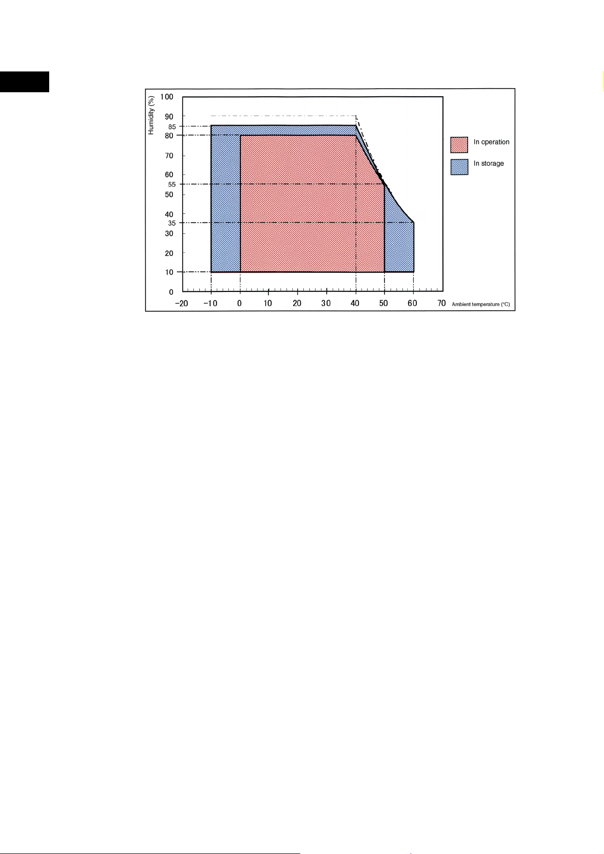
Ambient operating temperature 0 to 50°C (See notes 1 and 2.)
Ambient storage temperature −10 to 60°C (See note 2.)
Ambient operating humidity 10% to 80% with no condensation (See note 2.)
Ambient storage humidity 10% to 85% with no condensation (See note 2.)
Operating atmosphere
Noise resistance Conforms to IEC6100-4-4, power supply line: 2 kV
Vibration resistance (in
operation)
Shock resistance (in operation)
Dimensions (excluding
protrusions)
Weight NSA12: 5 kg max., NSA15: 7 kg max.
Degree of protection Front panel: IP65 or the equivalent (display side only) (See note 3.)
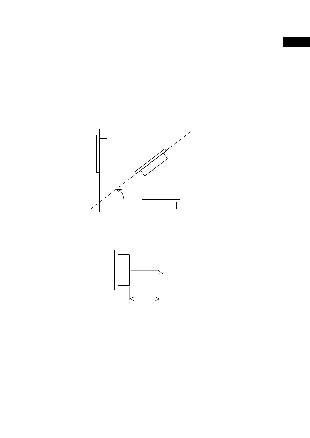
Note 1: The maximum surrounding air temperature rating is 50°C. The ambient operating
temperature may be restricted as described below depending on whether a PCI Board
is installed, the type of Board installed, and the mounting angle of the Unit.
■ Note 1-1: No PCI Board or One of Following Expansion Boards Installed
(1) The ambient operating temperature is 0 to 25°C when the installation angle is
(2) The ambient operating temperature is 0 to 30°C when the installation angle is
(3) The ambient operating temperature is 0 to 40°C when the installation angle is
(4) The ambient operating temperature is 0 to 50°C when the installation angle is
Must be free of corrosive gases.
Must be fairly dust free.
Conforms to JIS C0041, 0.05-mm amplitude at 10 to 55 Hz for 50 min each
in the X, Y, and Z directions
Conforms to JIS C0041, 196 m/s
directions
NSA12: 322 mm x 264 mm x 100 mm (W x H x D)
NSA15: 384 mm x 312 mm x 108 mm (W x H x D)
• 3G8F7-CLK21-V1 Controller Link Board (hereafter CLK Board)
• CS1PC-PCI01-DRM SYSMAC CS1 Board (hereafter CS1 Board)
greater than 0° and less than 15° off horizontal (excluding the memory card).
greater than 15° and less than 45° off horizontal (excluding the memory card).
greater than 45° and less than 75° off horizontal (excluding the memory card).
greater than 75° and less than 90° off horizontal (excluding the memory card).
2
three times each in the X, Y, and Z
1-4
Page 29
1-2 Specifications
1-2-2 General Specifications
■ Note 1-2: PCI Board Other Than a CLK Board or a CS1 Board Installed
The internal temperature of the PCI Board will rise 10°C at slot 1 and 15°C at slot 2.
This may place the ambient operating temperature at the high end of the range given
in *1-1 above. Therefore, set the ambient operating temperature according to the
ambient operating temperature of the PCI Board that is installed. Check prior to actual
use to make sure the PCI Board will operate properly at the selected ambient
operating temperature.
Example: If a PCI Board with an ambient operating temperature of 0 to 45°C will be
installed in slot 1 with the Unit installed at angle greater than 45° and less
than 75° off horizontal, then the ambient operating temperature selected
should be 0 to 35°C because of the 10°C rise in the internal temperature
of the Board at slot 1.
90°
1
Overview and Specifications
Installation angle
LCD display side
■ Note 1-3: Ambient Operating Temperature
The ambient operating temperature is the temperature at a point 50 mm from the
center of the back of the Unit, and it includes the heat generated by the Unit itself.
LCD
side
Back of the Unit
Ambient temperature
measuring point
50 mm
0°
1-5
Page 30
1-2 Specifications
1-2-2 General Specifications
1
Overview and Specifications
■ Note 2: Use the temperature and humidity ranges in the following diagram.
■ Note 3: The Unit may not operate properly in locations subjected to oil splashes for extended
periods of time.
1-6
Page 31

1-2 Specifications
1-2-3 Dimensions and External Appearance
1-2-3 Dimensions and External Appearance
1
Overview and Specifications
1-7
Page 32

1-2 Specifications
1-2-3 Dimensions and External Appearance
1
Overview and Specifications
1-8
Page 33

Section 2 Nomenclature
Page 34

2-1 Nomenclature
r
2-1-1 Front Panel
2-1 Nomenclature
2-1-1 Front Panel
2
Nomenclature
2-1-2 Rear Panel
Side Cover Fastening Screws
Loosen these three screws to remove the Side Cover.
POWER Indicator
Green lamp is lit when the power is ON.
Display Area
The entire display area is a touch panel and
input device.
Side Cover
Remove the Cover to install a PCI
Board or to set the DIP switch.
View with Side
Cover removed
Functional Ground Termin al
This terminal prevents noise-induced
This indicator is disabled during normal operation and enabled
malfunctions.
The red lamp is lit when a RAS failure occurs.
DIAG Indicator
only during RAS Board self-diagnosis.
ERR Indicato
PCI Board Connector
Use this Connector to install a PCI
Board.
RAS Board
Use this Board to monitor the
status of the Unit.
UPS Power Interrupt Signal Connector
This connector is used for the power interrupt signal from the UPS.
BATLOW Indicator
The red lamp is lit wh en t h e RAS Board backup batt er y is e xha usted.
RUN Indicator
The red lamp is flashing while the RAS Board is operating.
2-2
Page 35

COM Port 1 Connect or
r
r
r
r
A 9-pin RS-232C c o nn ector
2-1 Nomenclature
2-1-3 Connectors and Interfaces
COM Port 2 Connector
A 9-pin RS-232C c o nn ector.
Ethernet Connec t or
An Ethernet ca ble connector. It is an 8-p in 10 BASE-T/100
.
BASE-TX modular plug.
Mouse Connecto
A PS/2 mouse connector
Keyboard Connecto
A PS/2 keyboard connector.
USB Port 0 Connecto
A USB type A connector.
USB Port 1 Connecto
A USB type A connector.
.
Memory Card Cover
The cover that keeps the CF Card in place.
Memory Card Connect or
The CF Card connector.
PCI Board Slot 1
PCI Board Slot 2
Power Supply Input
The power supply input terminal.
2-1-3 Connectors and Interfaces
■ USB Connector (USB Ports 0 and 1)
NSA-series Industrial PC connector: Standard USB type A Connector
Pin No. Signal
1 V
2 D−
1 2 3 4
3 D+
4 GND
■ RS-232C Connector (COM Ports 1 and 2)
NSA-series Industrial PC connector: 9-pin male D-SUB Connector (See note
1.)
Pin No. Signal
1 CD Carrier Detect
2 RD Receive
3 TD Send
4 DTR Data Terminal Ready
5 GND Signal ground
6 DSR Data Set Ready
7 RTS Request To Send
8 CTS Clear To Send
9 RI Ring Indicator
Note 1: Use an SAE screw (4-40UNC) for the connector on
the NSA-series Industrial PC.
BUS
2
Nomenclature
2-3
Page 36

2
Nomenclature
2-1 Nomenclature
2-1-3 Connectors and Interfaces
■ Ethernet Connector
NSA-series Industrial PC connector: RJ45
100Mbps LINK Indicator
The green lamp is lit for 100-Mbps c onnection.
TX/RX ACT Indicator
The orange lamp is lit when
sending or receiving via Ethernet .
Pin No. Signal
1 TD+ Twisted pair send +
2 TD- Twisted pair send 3 RD+ Twisted pair receive +
4 NC Not used
5 NC Not used
6 RD- Twisted pair receive 7 NC Not used
8 NC Not used
Note
Confirm the safety of the system before turning the power ON or OFF.
■ PS/2 Keyboard Connector
NSA-series Industrial PC connector: 6-pin female Mini-DIN Connector
6 5
4 3
2 1
Pin No. Signal
1 DATA Keyboard data
2 NC Not used
3 GND Signal ground
4 +5V +5 V output
5 CLK Keyboard clock
6 NC Not used
■ PS/2 Mouse Connector
NSA-series Industrial PC connector: 6-pin female Mini-DIN Connector
6 5
4 3
2 1
Pin No. Signal
1 DATA Mouse data
2 NC Not used
3 GND Signal ground
4 +5V +5 V output
5 CLK Mouse clock
6 NC Not used
■ UPS Power Interrupt Signal Connector
NSA-series Industrial PC connector: S3B-PH-K-S (J.S.T. Mfg. Co., Ltd.)
Pin No. Signal
1 2 3
1 ACFAIL
2 NC
3 COM
Note: Set the ACFAIL input voltage to 24 V±10%.
2-4
Page 37

2-1 Nomenclature
2-1-3 Connectors and Interfaces
z Equivalent Input Circuit
The NSA-series Industrial PC can read a power interrupt detection signal from the
UPS by supplying power after an open condition occurs between the input
connector terminals or by creating an open condition between the input connector
terminals after power is supplied.
24 VDC (10 mA max.)
COM
UPS
Input connector
Pin 1
Pin 3
NSA
2
Nomenclature
Note
• Never use a chemically treated cloth or volatile solvents, such as benzene or
thinner, to clean the NSA-series Industrial PC.
• Input may fail if the touch panel is pressed continually at high speed. Confirm
each input before moving on to the next entry.
• If the same image is left on the screen for an extended period of time, that
image will be burned into the screen permanently. Use the burn-in prevention
function or periodically change the screen to prevent permanent damage to the
screen.
• The entire system may shut down depending on how the power is turned ON or
OFF. Follow the correct procedure for turning the power ON or OFF.
2-5
Page 38

2
Nomenclature
2-1 Nomenclature
2-1-3 Connectors and Interfaces
2-6
Page 39

Section 3
Installing the NSA-
series Industrial PC
and Connecting
Peripheral Devices
Page 40

3-1 Basic Operating Procedures
3-1 Basic Operating Procedures
3
Installing the NSA-series Industrial PC and Connecting Per ipher al Devices
This section describes the basic steps for operating the NSA-series Industrial PC.
Step 1 Install a PCI Board and set the DIP switch (using a PCI Board
and Special RAS Board monitoring functions).
In the following situations, remove the side cover and install the PCI Board or set
the DIP switch first before you install the NSA-series I ndustrial PC in an operating
panel.
• To install and use a PCI Board.
• To enable the RAS Board’s special Action on Error monitoring function
(forced shutdown or forced reboot)
• To set the ACFAIL signal input method for the external input port (UPS
power interrupt signal connector) to “Normally supplies 24 V; Open at
PWR-FAIL.”
Step 1 Remove the side cover.
↓
Step 2 Set the DIP Switch.
↓
Step 3 Install the PCI Board.
↓
Step 4 Reattach the side cover.
↓
Step 2 Install the NSA-series Industrial PC and wire it to the operating
panel.
↓
Step 3 Make PS/2 port connections.
If a PS/2 keyboard or PS/2 mouse will be used, connect these devices bef or e you
turn ON the NSA-series Industrial PC. Insert a memory card (CF Card) if needed
and make any USB, RS-232C, or Ethernet connections that may be required.
↓
Step 4 Turn ON the 24 V DC external power supply and start the
operating system.
Note
Connect a 24 V DC power supply.
Note: Never connect an AC power supply. Otherwise the NSA-series Industrial PC
will be damaged.
• The timer startup function available from the special RAS Board enables the
NSA-series Industrial PC to be turned ON at a specified time as long as the
external 24 V DC power supply is turned ON.
• The startup and shutdown monitoring functions available from the special RAS
Board enable operating system monitoring to determine whether or not the OS
started up a specified amount of time after the power was turned ON or a
specified amount of time after the system shutdown.
• The C: and D: drives are defined in the NSA-series Industrial PC. When a
Memory Card is being used, use a drive letter other than C: or D:.
↓
3-2
Page 41

3-1 Basic Operating Procedures
Step 5 Make non-PS/2 port connections and insert card.
A memory card (CF Card) can be inserted and USB, RS-232C, or Ethernet
connections can be made after the power is turned ON.
↓
Step 6 Adjust the touch panel and display.
Adjust (calibrate) the touch panel positioning as needed.
• Touch panel positioning adjustment (calibration): The pre-installed
universal pointer device driver (UPDD) program is used to calibrate the
touch panel.
↓
Step 7 Start up the application.
3
Installing the NSA-series Industrial PC and Connecting Per ipher al Devices
3-3
Page 42

3-2 Installing a PCI Board and Setting the DIP Switch
3-2 Installing a PCI Board and Setting
3
Installing the NSA-series Industrial PC and Connecting Per ipher al Devices
the DIP Switch
Follow the steps below to install a PCI Board or to change the default set t ing of
the DIP switch.
Removing the Side Cover
Note
Be sure to turn OFF the NSA-series Industrial PC power supply (external input power
supply) before you remove the side cover and set the DIP switch.
1. Turn OFF the NSA-series Industrial PC power supply (external input power
supply) and loosen the three screws securing the side cover.
Side cover
fastenin g sc r ews
3-4
Page 43

3-2 Installing a PCI Board and Setting the DIP Switch
2. Remove the side cover.
3
Installing the NSA-series Industrial PC and Connecting Per ipher al Devices
Setting the DIP Switch
Set the DIP switch only to enable the RAS Board’s special Action on Error
monitoring function or to set the ACFAIL signal input method for the ext ernal input
port (UPS power interrupt signal connector) to “Normally supplies 24 V; Open at
PWR-FAIL.”
• Setting the DIP Switch
RAS Function Settings (Hardware Settings)
Pin
No.
1 Not used (Default setting: OFF)
2 Not used (Default setting: OFF)
3
4 Not used (Default setting: OFF)
5 Not used (Default setting: OFF)
6
7 Always OFF
8 Enables and disables the Action on Error operation of the special RAS
Note: Select the appropriate input method for the system you are using.
Not used (Default setting: OFF)
Specifies the ACF AIL signal input method f or the external input port (UPS power
interrupt signal connector). (See note.)
ON: Normally supplies 24 V ; Open at PWR-FAIL.
OFF: Normally open; supplies 24 V at PWR-FAIL. (Recommended/default
setting.)
Board monitoring functions (alive, startup, and shutdown monitoring).
ON: Disables operation when there is an error.
OFF: Enables operation when there is an error (factory setting).
Function
3-5
Page 44

3-2 Installing a PCI Board and Setting the DIP Switch
y
3
Installing the NSA-series Industrial PC and Connecting Per ipher al Devices
Installing a PCI Board
1. Remove the single screw shown in the figure below to detach the metal plate cover for
the PCI slot.
Screw
Motherboard
batter
Metal plate cover for the
PCI slot
2. Insert the PCI Board into the PCI Board mounting connector.
RAS board
battery
PCI Board
3-6
Page 45

3-2 Installing a PCI Board and Setting the DIP Switch
3. Secure the PCI Board with the screw that was removed from the met al plate
cover in step 2.
Screw
3
Installing the NSA-series Industrial PC and Connecting Per ipher al Devices
Reattaching the Side Cover
Reattach the side cover and tighten the three screws that were loosened in step 1
to remove the cover.
Note
• Use a PCI Board that complies with the EMC Directive. If a PCI Board that does not
comply with the EMC Directive is used, there are certain measures that the user
must take.
• Be sure to turn OFF the NSA-series Industrial PC power supply (external power
supply) before you remove the side cover and install or remove a PCI Board.
• Refer to the following diagram for mountable board sizes.
• Check the PCI Board that will be used to make sure it operates properly prior to
actual operation.
• The maximum power available at the two PCI Board slots is 5 VDC/2.1 A and 3.3
VDC/1.0 A, respectively.
• There may be ambient operating temperature restrictions depending on the PCI
Board that is used. Make sure the Board is operating within the stipulated
temperature range.
3-7
Page 46

3-2 Installing a PCI Board and Setting the DIP Switch
3
Installing the NSA-series Industrial PC and Connecting Per ipher al Devices
Reference Diagram for PCI Board Size
174.63 mm
max.
106.68 mm max.
Dimensional Reference Diagram with PCI Board Mounted
RAS board
battery
Motherboard
battery
3-8
Note
Be sure to check the PCI Board in the actual equipment to make sure it will operate
properly after it is installed.
Page 47

3-3 Installing the NSA-series Industrial PC
3-3-1 Environment
3-3 Installing the NSA-series Industrial
PC
3-3-1 Environment
Observe the following points for panel mounting and other NSA-series Industrial PC
installations.
Note
Note
Do not install the Unit in the following places:
• Locations subject to severe temperature changes
• Locations subject to temperatures or humidity outside the range specified in the
specifications
• Locations subject to condensation as the result of severe changes in humidity
• Locations subject to exposure to chemicals and other harsh substances.
• Locations subject to intense exposure to oil
• Locations subject to corrosive or flammable gases
• Locations subject to shock or vibration
• Outdoor locations subject directly to wind and rain
• Locations subject to intense ultraviolet rays
Take appropriate and sufficient countermeasures when installing systems in the
following locations:
• Locations subject to static electricity or other forms of noise
• Locations subject to strong electromagnetic fields
• Locations close to power supplies
• Locations subject to possible exposure to radioactivity
When unpacking the product, check carefully for any external scratches or other
damage. Also, shake the product gently and check for any abnormal sound.
3
Installing the NSA-series Industrial PC and Connecting Peripheral Devices
3-9
Page 48

3-3 Installing the NSA-series Industrial PC
3-3-2 Installing the NSA-series Industrial PC in a Control Panel
3-3-2 Installing the NSA-series Industrial PC i n a Contr ol Panel
3
Installing the NSA-series Industrial PC and Connecting Peripheral Devices
The NSA-series Industrial PC is normally mounted in a panel. Follow the steps
below to mount the Unit.
1. Cut the mounting hole out from the panel.
Panel thickness: 1.6 to 4.0 mm
2. Insert the NSA-series Industrial PC into the hole from the front of the panel.
2. Use the Mounting Brackets provided to secure the NSA-series Industrial PC in
the panel. Tighten the Mounting Brackets evenly to the specified torque.
Failure to do so may cause the front sheet to buckle.
Tightening torque: 0.5 to 0.6 N·m
3-10
Page 49

Note
3-3 Installing the NSA-series Industrial PC
3-3-3 Connecting the Power Supply
3
Installing the NSA-series Industrial PC and Connecting Peripheral Devices
• The mounting panel must be between 1.6 and 4.0 mm thick.
• Tighten the Mounting Brackets evenly to a torque of between 0.5 and 0.6 N·m to
maintain water and dust resistance. Make sure the panel is not dirty or warped and
that it is strong enough to hold the product.
• Do not let metal particles enter the product when preparing the panel.
3-3-3 Connecting the Power Supply
Connect a 24 V DC power supply to the power terminals on the NSA-series
Industrial PC.
Note
• Do not connect an AC power supply to the power terminals.
• Do not perform a dielectric voltage test.
• Use a DC power supply with minimal fluctuation range
• Use an isolating source. Be sure to connect a DC power supply with reinforced
insulation to the NSA-series Industrial PC. The DC output side power supply should
not be grounded on one end.
3-11
Page 50

3-3 Installing the NSA-series Industrial PC
3-3-4 Connecting the Grounding Wire
3
Installing the NSA-series Industrial PC and Connecting Peripheral Devices
Power Supply
The following specifications are requirements for power supplies that can be
connected to the NSA-series Industrial PC. Select a power supply that sat isf ies
the capacity requirement.
Item Value
Supply voltage 24 V DC
Allowable power supply voltage range 20.4 to 27.6 V DC (24 V DC±15%)
Power supply capacity NSA12: 80 W min, NSA15: 100 W min.
Breaker
24 V DC power supply
Connecting Parts
Note
Connect to the power supply terminal block using a twisted-pair cable with copper wire
between AWG16 and AWG12, with a minimum temperature rating of 75°C. Tighten the
terminal screws to a torque of 0.5 to 0.6 N·m (5 to 7 lb·in). Be sure the screws are
properly tightened.
Prepare the connection wires as shown in the figure below. Make sure the bare
wires are twisted tightly together.
3-3-4 Connecting the Grounding Wire
The NSA-series Industrial PC has a functional grounding terminal ( ). Make sure
the terminal is properly grounded to prevent the Unit from malfunctioning due t o
electrical noise.
3-12
Functional
grounding
terminal
Attach a crimp terminal for an M4 screw to the grounding wire.
Page 51

Note
3-3 Installing the NSA-series Industrial PC
3-3-4 Connecting the Grounding Wire
8 mm max.
• Do not install the NSA-series Industrial PC in the same panel as a noise-
generating device like a motor or inverter.
• Make sure the NSA-series Industrial PC is properly grounded to prevent the
Unit from malfunctioning due to electrical noise.
3
Installing the NSA-series Industrial PC and Connecting Peripheral Devices
3-13
Page 52

3-4 Starting the Industrial PC and Procedure after Power Interruption
3-4-1 Operation
3-4 Starting the Industrial PC and
Procedure after Power Interruption
Make sure that the power supply connected to the NSA-series Industrial PC
satisfies the following specifications for NSA-series Industrial PC st art up and
power interruption.
3
Installing the NSA-series Industrial PC and Connecting Peripheral Devices
3-4-1 Operation
Starting the Operating System
If the external 24 V DC input voltage is turned OFF, the NSA-series Industrial PC
operating system will start up when the rat ed input volt age is supplied t o t he NSAseries Industrial PC. The input voltage must remain OFF for at least 10 s bef ore it
is turned back ON. (OFF/ON interval: 10 s min.)
Shutting Down the Operating System
The NSA-series Industrial PC shuts down the operating system when it receives a
shutdown request from a software application, or when the user executes a
shutdown operation. When the shutdown is completed, the NSA-series Indust rial
PC will turn OFF all DC outputs except the 5-Vs auxiliar y power supply.
Power Interruptions
If the 24 V DC input voltage from the exte rnal power supply is int errupted, all
NSA-series Industrial PC power supplies, including the 5-Vs auxiliary power
supply, will turn OFF. If th is occur s dur ing any oper at ion, including shutdown, that
operation may not be successfully completed. Be sure to turn OFF the external 24
V DC input voltage after the shut down is completed. The NSA-series Industrial
PC does not have UPS or other recovery functions for power outages or power
interruptions. These functions will have to be provided exter nally ( on t he syst em
side).
3-14
Page 53

3-4 Starting the Industrial PC and Procedure after Power Interruption
y
y
3-4-2 Operating Sequence for the External Power Supply
3-4-2 Operating Sequence for the External Power Supply
The following diagram shows the power supply control sequence under normal
operating conditions.
External input
Input voltage
held OFF for at
least 10 s.
Do not turn OFF the input
voltage while the NSA is
operating.
10 s min.
NSA built-in power suppl
(excluding the 5-Vs auxiliar
power supply)
NSA
Note
• If the external input voltage is interrupted, it must remain OFF for at least 10 s
• If the external input voltage is interrupted during any operation, including
• Make sure that the power supply connected to the NSA-series Industrial PC
• The entire system may shut down depending on how the power is turned ON
OS shutdown begins
NSA operating
NSA starts up
NSA starts up
OS shutdo wn ends
before it is turned back ON. (OFF/ON interval: 10 s min.)
shutdown, that operation may not be successfully completed. Shut down the
NSA-series Industrial PC and turn OFF the external 24 V DC input voltage.
The NSA-series Industrial PC does not have UPS or other recovery functions
for power outages or power interruptions. These functions will have to be
provided externally (on the system side).
satisfies the following specifications for NSA-series Industrial PC startup and
power outages.
or OFF. Follow the correct procedure for turning the power ON and OFF.
3
Installing the NSA-series Industrial PC and Connecting Peripheral Devices
3-15
Page 54

3-4 Starting the Industrial PC and Procedure after Power Interruption
3-4-3 Installation Procedure
3-4-3 Installation Procedure
3
Installing the NSA-series Industrial PC and Connecting Peripheral Devices
Follow the steps below to mount the memory card to the connector at the bot t om
of the NSA-series Industrial PC.
Install/Remove
Installed
Rear
Notch
Enlarged Memory Card Diagram
Back of
Memory Card
Side View
Notch
Insert the Memory Card with the backside facing
forward. The backside is the side with the notches
and protrusion.
Eject Button
Protrusion
Protrusion
3-16
1. Loosen the thumbscrew on the memory card cover, rotate the cover up to the
Install/Remove position, and secure the cover in place.
2. Push the memory card in firmly as far as it will go. The Eject Button will pop out
when the memory card is secured in place.
3. Loosen the thumbscrew on the memory card cover, rotate the cover down to
the Installed position, and secure the cover in place.
Page 55

3-4 Starting the Industrial PC and Procedure after Power Interruption
3-4-4 Removal Procedure
1. Loosen the thumbscrew on the memory card cover, rotate the cover up to the
Install/Remove position, and secure the cover in place.
2. Press the Eject Button. Use your middle finger to press the Eject Button and
place your index finger in front of the memory card to keep it from popping out
and falling on the floor.
Note
• Use only a CF (Compact Flash) Card that has CE Markings.
• Thoroughly test the memory card that will be used to confirm that it operates
properly before actually using it with the product. Some memory cards may not
be compatible. Also, use a memory card with an ambient operating
temperature range between –5 and 85
3-4-4 Removal Procedure
3
Installing the NSA-series Industrial PC and Connecting Peripheral Devices
°C.
3-17
Page 56

3-5 Adjusting the Touch Panel and Display
3-5-1 Calibrating the Touch Panel
3-5 Adjusting the Touch Panel and
3-5-1 Calibrating the Touch Panel
3
Installing the NSA-series Industrial PC and Connecting Peripheral Devices
Display
This section describes the procedure for calibrating the touch panel.
1. Connect a PS/2 keyboard and mouse or a USB keyboard and mouse to
the NSA-series Industrial PC to calibrate the touch panel whenever it deviat es
markedly from its coordinates. Make sure the keyboard and mouse are
properly connected.
Note
Shut down the NSA-series Industrial PC operating system and turn OFF the NSA-series
Industrial PC before you connect the PS/2 keyboard and mouse.
2. Start up the NSA-series Industrial PC and select Start – Programs – UPDD –
Settings from the bottom left corner of the screen to launch the settings
program.
3. Click the Calibration Tab on the Pointer Device Properties Menu, then click
the Calibrate Button.
Settings
3-18
Calibrate Button
Make sure the EEPROM
Calibration box is checked.
Page 57

3-5 Adjusting the Touch Panel and Display
3-5-1 Calibrating the Touch Panel
4. The calibration screen will appear. Touch the tip of the arrow on the touch panel
screen. When that calibration point is entered, an ar r ow will appear in anot her
location. Touch the tip of the each arrow that appears.
Touch the t ip of the arrow to input a cali bration point.
3
Installing the NSA-series Industrial PC and Connecting Peripheral Devices
Note
Note
5. After all the calibration points have been entered, the Check calibration dialog
box will appear. A message will be displayed prompting you to save the
calibration data. If there were no problems with the calibration points, press t he
OK Button or the Enter Key on the keyboard. If there was a problem with a
calibration point, do not touch anything for 10 seconds. The calibration data will
be discarded and will not be saved.
OK Button
The touch panel may deviate from its coordinates over time. We recommend that you recalibrate the touch panel whenever that occurs.
The calibration data is stored on the EEPROM in the NSA-series Industrial PC. If the
EEPROM calibration box is not checked, the calibration data will be stored in Windows.
3-19
Page 58

3-5 Adjusting the Touch Panel and Display
3
Installing the NSA-series Industrial PC and Connecting Peripheral Devices
3-20
Page 59

Section 4 RAS Functions
Page 60

4
RAS Functions
4-1 RAS Function Details
4-1-1 What Is the RAS Solution for OMRON Industrial PCs ?
4-1 RAS Function Details
NSA-series Industrial PCs are equipped with standard PC RAS functions and
other unique RAS functions that can be used to construct highly reliable systems.
4-1-1 What Is the RAS Solution for OMRON Industrial PCs ?
RAS functions have important roles in various business scenes using industrial
PCs, where high reliability of a PC is required, as well as advanced features and
high performance. The OMRON RAS Solution is a comprehensive capability to
constantly monitor the system status and send information on any detected error to
users and the system. RAS functions can shutdown and/or enable the system to
recover safely.
An OMRON Industrial PC embedded with a specific RAS Board can greatly
enhance reliability through a RAS system that combines RAS Middleware and a
RAS Utility. The RAS system in an OMRON Industrial PC provides main the
following functions:
• A Monitoring Function is provided to constantly monitor the hardware and
software of the industrial PC and provide the user failure notification when an
error is detected or a failure occurs.
• An Auto-recovery Function forcefully shuts down the system when a failure
occurs to prevent further faults and reboot the system for recovery.
• A Logging Function saves events in operating the industrial PC (such as
power supply ON/OFF events, OS startup/shutdown events, etc.), system
status when a failure occurs, and conditions of the motherboard (i.e., the
temperature and power supply) in RAS Board memory backed up by a battery.
• The Log Analysis Function analyzes the cause and/or tendency of failures
using large amounts of log data saved in memory.
4-1-2 Monitoring and Auto-recovery
Monitoring Functions
The RAS functions enable users to monitor operation status and detect failures.
The Industrial PC provides the following monitoring functions.
• Startup Monitoring: Provides notification of failures that occur while starting
(i.e., from turning ON the power supply until startup has been completed).
• Alive Monitoring: Provides notification of failures that occur while the OS is
running (i.e., from startup to shutdown).
4-2
Page 61

4-1-3 Logging Function and Log Analysis Function
• Shutdown Monitoring: Provides notification of failures that occur while shutting
down or rebooting.
• External Power Supply Undervoltage/Interruption Monitoring: Detects
abnormal power interruptions for the external power supply.
• Temperature Monitoring: Detects abnormal temperatures in the Motherboard.
• Voltage Monitoring: Detects abnormal power supply voltages in the
Motherboard.
• Cumulative Operating Time Monitoring: Detects excessive cumulative
operating time.
• RAS Board Monitoring: Detects errors in the RAS Board.
• LCD Monitoring: Detects errors in the LCD.
Action on Error (Forced Shutdown/Forced Reboot)
This function can enable systems to recover to improve the operation rate or
terminate the system to prevent further faults after detecting a failure.
OMRON Industrial PCs with RAS functions have the following capabilities:
• Rebooting the system automatically when the operating system freezes,
• Starting the system and restoring operation automatically after the Motherboard
stops because of a failure, such as overheating due to runaway operation,
• Repeating reboot attempts automatically until the system is successfully
activated, if the system hangs up at startup, and
• Forcefully terminating the system automatically when the system takes too much
time to shut down.
4-1 RAS Function Details
4
RAS Functions
Failure Notification
The Failure Notification function reports a failure when the failure occurs or after
the system recovers from the error. It notifies the user of a failure with a pop-up
message that allows the user to immediately identify the situation without fail.
• The user is notified of power failure that causes shutdown of the system.
• When the system goes down due to some failure, this function notifies the user
of the nature of the failure and the status of the Industrial PC after the system
recovers from the error.
• The user is immediately notified of any abnormal temperature or voltage in the
Motherboard.
• The user is notified that LCD Backlight lifetime is nearing its limit.
Status Monitor
The industrial PC’s operating status can be monitored from the RAS Utility. The
following RAS information can be monitored:
• Motherboard temperatures (CPU temperature and chipset temperature),
• Motherboard voltages (2.5 V, Vccp, VTR, 5 V, 12 V, HVCC, 1.5 V, and 1.8 V
values),
• Cumulative operating times (motherboard/LCD and RAS Board),
• RAS system settings,
• LCD operating status,
• RAS Board operating status,
• Number of errors that have occurred, and
• Failure status.
4-1-3 Logging Function and Log Analysis Function
The system keeps a log of operational events as well as of the status of the
Industrial PC (temperature, voltage, etc.) in memory. The logs are saved in the
RAS Board memory even if the Industrial PC cannot start due to a failure, so the
user can analyze the log based on the information stored in the RAS memory in
4-3
Page 62

4
RAS Functions
4-1 RAS Function Details
4-1-4 Architecture
order to identify the cause of the failure. The RAS Utility includes Filter and Find
functions to analyze logs. These functions allow the user to analyze the logs more
effectively by specifying events in a particular period or classifying events in
categories.
The RAS Utility allows the user to import/export log files. The user may export log
files to save logs to a file on a regular basis. The user may also import log files to
compare and analyze past logs with logs currently in the memory or to conduct log
analysis on another OMRON Industrial PC.
4-1-4 Architecture
An OMRON Industrial PC’s RAS system functions are achieved with the RAS
Board, RAS Middleware (RAS Service), and RAS Utility.
RAS Board: This is expansion hardware used to monitor failures that occur in the
software/hardware of an OMRON Industrial PC. The RAS Board can restart the
system to recover normal operation when it detects a failure. Additionally, it saves
power supply ON/OFF status, OS startup/shutdown status, and logs of various
failures in the memory backed-up by a battery. This enables the user to analyze
the conditions when failures occur and identify trends.
RAS Middleware: This software operates as part of Windows services. It
communicates with the RAS Board to allow the detection of failures in the
operating system. It also serves as an interface between the RAS Utility and RAS
Board.
RAS Utility: This is a resident application that is automatically activated when
Windows starts. When the RAS Utility detects a failure in the RAS Board, it
provides notification of the failure through a pop-up message that immediately
identifies the failure situation. The RAS Utility also provides functions to analyze
logs that are saved in the RAS Board memory, allowing efficient analysis of the
conditions when failures occur and trends. Additionally, the RAS Utility allows the
OMRON Industrial PC’s RAS functions to be set flexibly, including the RAS Board
settings.
RAS Utility periodically
reads the status of RAS
Board/Motherboard
• Hardware Monitoring
• Software Monitoring
• Recovery
(Power OFF/Reset)
Software
RAS Utility
RAS Middleware (RAS Service)
OS (Windows XP Embedded)
Hardware
Motherboard
LCD
RAS Board
Memory
• Shows a dialog to report errors
• Log Analysis
• Configuring RAS Syst em
RAS Board periodically
communicates with the RAS
Middleware to monitor the OS to
see if it is operating.
Monitoring results are
stored in the memory.
4-4
Page 63

4-2 Special RAS Board Functions
4-2-1 Special RAS Board Functions
4-2 Special RAS Board Functions
The following RAS functions are available when an NSA-series Industrial PC RAS
Board is installed.
4-2-1 Special RAS Board Functions
Function Description
Alive monitoring Provides notification of failures that occur while the OS is running (i.e.,
from startup to shutdown). The RAS Board periodically communicates
with the RAS Middleware on the Motherboard to monitor the OS status.
Startup monitoring Provides notification of failures that occur while starting (i.e., from
turning ON the power supply until startup has been complete d).
Monitors startup after the power supply is turned ON to see if startup is
completed within the set time.
Shutdown monitoring Provides notification of failures that occur while shutting down or
rebooting. Monitors shutdown after a command to shut down the OS
has been given to see if shutdown is completed within the set time.
Action on error
(forced shutdown or
forced reboot)
External power supply
monitor
Timer start Turns ON the power supply of the Industrial PC at the specified time.
Motherboard/LCD
operating time
measurement
Log function Enables saving and reading log data.
Recover processing will be automatically performed when there is
notification of a failure. If a forced shutdown is specified, the power
supply to the Industrial PC will be turned OFF. If a forced reboot is
specified, the power supply to the Industrial PC will be turned OFF and
then back on to reboot.
Monitors the external power supply for abnormal power interruptions.
Measures the operating time of the Motherboard and LCD backlight.
4
RAS Functions
4-2-2 Setting Procedure
The NSA-series Industrial PC DIP switch must be set to enable the special RAS
Board functions.
Setting the DIP Switch
Set the correct DIP switch settings for the operating environment before you use
the NSA-series Industrial PC for the first time. Remove the side cover to set the
DIP switch. Refer to 3-2 Installing a PCI Board and Setting the DIP Switch for
details on removing the side cover.
Note
Be sure to turn OFF the NSA-series Industrial PC power supply (external input power
supply) prior to removing the side cover and setting the DIP switch.
4-5
Page 64

4
RAS Functions
4-2 Special RAS Board Functions
4-2-2 Setting Procedure
z Setting the DIP Switch
RAS Function Settings (Hardware Settings)
Pin
No.
1 Not used (Default setting: OFF)
2 Not used (Default setting: OFF)
Not used (Default setting: OFF)
3
4 Not used (Default setting: OFF)
5 Not used (Default setting: OFF)
Specifies the ACFAIL signal input method for the external input port (UPS power interrupt
signal connector). (See note.)
6
ON: No rmally supplies 24 V ; Open at PWR-FAIL.
OFF: Normally open; supplies 24 V at PWR-FAIL. (Recommended/default setting.)
7 Always OFF
Enables and disables the Action on Error operation of the special RAS
Board monitoring functions (alive, startup, and shutdown monitoring).
8
ON: Disables operation when there is an error.
OFF: Enables operation when there is an error (factory setting).
Note: Select the appropriate input method for the system you are using.
Function
4-6
Page 65

4-3 Motherboard RAS Functions
4-3-1 Standard PC RAS Data
4-3 Motherboard RAS Functions
The NSA-series Industrial PC can read standard PC RAS data (voltage,
temperature, fan rpm). It also has additional unique RAS functions, such as POST
error logging, POST error retry, and CMOS data recovery.
4-3-1 Standard PC RAS Data
The NSA-series Industrial PC can read the following standard PC RAS data.
Note
No. Monitored
hardware data
CPU temperature
1
sensor
No. of fan rotations
2
(See note.)
3 Board voltage
4 POST error logs
Note: The NSA-series Industrial PC does not have a fan.
Temperature data read via the SMBus interface
(hardware monitor interface). (Not converted to degrees
centigrade)
Fan rpm (2 fans) and the fan log (per fan) re ad via the
SMBus interface (hardware monitor interface). (Not
converted to rotations per minute)
Voltages read via the SMBus interface (hardware monitor
interface). The following voltages can be read.
HVCC (3.3 V)
V12 (+12 V)
V5 (+5 V)
VTR (3.3 V)
V25 (+2.5 V)
Vccp
V18 (+1.8 V)
V15 (+1.5 V)
(Not converted to voltage)
BIOS startup log data (approximately 40 bytes for the 10
most recent errors) read from specified CMOS addresses
in the chipset.
Although the NSA-series Industrial PC will read RAS data from the super I/O chip
(SMSC LPC47M192) and the chipset (Intel 855GME+Intel 6300ESB) on the
motherboard, it does not do conversions, such as converting to degrees of temp erature.
Refer to respective datasheets for data processing (data conversion) details.
Description
4
RAS Functions
4-3-2 Unique RAS Functions
POST Error Log
When POST errors occur, the 4-byte POST error code, time, month, and date for
up to 32 errors are logged as individual POST error records. These records can be
read from the BIOS setup menu.
Error data can be retained indefinitely without relying on the internal battery for
backup because POST error logs are saved in the motherboard EEPROM. This
also means that error data can only be deleted from the BIOS setup menu.
Note: After 32 errors, the most recent error will overwrite the oldest error. Individual
error records cannot be deleted. If you delete one error record, they will all be
deleted.
4-7
Page 66

4
RAS Functions
4-3 Motherboard RAS Functions
4-3-2 Unique RAS Functions
POST Error Retry Function
z Normal Mode
The message Press the F1 Key to Resume, Press the F2 Key to Setup will be
displayed on the screen to abort the startup.
z Retry Mode
The message Press < F1> to Resume, <F2> to Setup will be displayed on the
screen for the amount of time specified at the timer setting. When that time has
elapsed, the system will attempt to restart and the process will repeat up to the
number of times specified in the retry counter setting. There are three options for
the next operation after the specified number of retries is exceeded: startup, stop,
or power OFF.
Function Setting Description
Retry Counter 1 to 15 Sets the number of retr ies.
Timer 1, 3, 5, 10, or 15 Sets the amount of time until the next retry.
Auto Resume
Power Off
z Auto Mode
The message Press < F1> to Resume, <F2> to Setup will be displayed on the
screen for the amount of time specified at the timer. Any errors will be ignored and
startup will resume.
Function Setting Operation
Timer 1, 3, 5, 10, or 15
Enabled
Disabled
Enabled
Disabled
Enables or disables whether to ignore the error
when the number of retries is exceeded and resume
startup.
Enables or disables power OFF when Auto Resume
is disabled.
Sets the amount of time until the next retry when an
error occurs.
NVRAM Function
The motherboard has a chipset with a 256-byte CMOS (banks 1 and 2) and a
512-byte EEPROM (bank 3) for CMOS expansion. Banks 1 and 2 must be backed
up by the internal battery and are used to store BIOS settings. Bank 3 does not
have to be backed up by the internal battery and is used to store backup BIOS
settings and POST error logs.
Bank Size Placement Occupied Size Application
Bank-1 128 bytes
Bank-2 128 bytes
Bank-3 512 bytes EEPROM
CMOS in
Chipset
CMOS in
Chipset
The EEPROM can only be initialized from the BIOS setup menu.
Function Setting Description
Clear EEPROM Press Enter
Note: Use with caution because initializing will also clear POST error log data.
128 bytes BIOS
88 bytes BIOS
40 bytes Reserved
256 bytes CMOS backup area
128 bytes POST error log storage area
128 bytes Reserved
Press the Enter Key to delete all data from the EEPROM
(0 clear).
4-8
Page 67

CMOS Data Recovery Function
BIOS can save BIOS settings to the CMOS and can restore those settings from the
CMOS.
Function Setting Description
Backup
CMOS
Restore
CMOS
Note: Clock data cannot be saved or restored.
Press Enter
Press Enter
4-3-3 Setting Procedure
BIOS Settings
The POST error retry, NVRAM, and CMOS data recovery functions can be set
from the BIOS setting screen.
4-3 Motherboard RAS Functions
4-3-3 Setting Procedure
Press the Enter Key to sa v e the current BIOS settings. The
message In progress, please wait will be displayed while
the settings are being saved.
Press the Enter Key to restore the last saved BIOS
settings. The message In progress, please wait will be
displayed while the settings are being restored.
4
RAS Functions
4-9
Page 68

4
RAS Functions
4-4 RAS Utility Functions
4-4-1 RAS Utility Functions
4-4 RAS Utility Functions
The RAS Utility software helps the user make the most of all of the RAS functions.
The RAS Utility is a resident application that is started automatically, and has the
following RAS functions.
4-4-1 RAS Utility Functions
Item Function
Failure Notification The Failure Notification function reports a failure when the failure
occurs or after system recovery. It notifies the user of a failure with a
pop-up message.
Status Monitor This function lists the industrial PC’s hardware and software status,
which is read periodically.
Log Analysis The causes of failures and failure trends can be analyzed efficiently
based on the log data stored in the RAS Board.
RAS Settings This function can be used to set the Industrial PC’s RAS settings,
including the RAS Board’s settings.
4-4-2 Setting the Failure Notification Function
The following procedure enables the Failure Notification Function.
1. The following window will be displayed just after the RAS Utility starts.
Click the RAS Utility Icon in the taskbar to display the pop-up menu and select Open to
open the window.
Click.
Select Open.
4-10
Page 69

4-4 RAS Utility Functions
4-4-2 Setting the Failure Notification Function
2. The followin g window will be displayed. Click the ON Button in the Failure Notification Area
to enable the Failure Notification Function.
Failure Notification
The icon shows the status of the Failure Notification Function.
4
RAS Functions
Failure Notification is enabled.
Failure Notification is disabled.
3. When Failure Notification is enabled, the following pop-up window will be displayed if a
failure occurs. The window will display details on the current failure.
Report
View More Detail
Button
Shutdown OS Button
Restart OS Button
Close this Window
Button
Note: For details on using this window, refer to the RAS Utility’s Help function.
4-11
Page 70

4
RAS Functions
4-4 RAS Utility Functions
4-4-3 Checking the PC’s Operating Status using the Status Monitor
4-4-3 Checking the PC’s Operating Status using the Status Monitor
Detailed information can be displayed on the Industrial PC.
• RAS Board: This tab page shows information on the occurrence of failures and the RAS
Board’s operating status.
• Motherboard: This tab page shows the Motherboard’s voltage and temperature information.
Note: For details on using this window, refer to the RAS Utility’s Help function.
4-12
Page 71

4-4 RAS Utility Functions
4-4-4 Log Viewer (Filter and Find)
4-4-4 Log Viewer (Filter and Find)
The RAS Utility obtains the log from the RAS Board and Motherboard. The log data can be
analyzed efficiently with the Filter and Find Functions.
Log List
4
RAS Functions
• Filter
Displays a list of the log data that meet the filter conditions.
• Find
Focuses on the log data that meets the search conditions.
Note: For details on using this window, refer to the RAS Utility’s Help function.
4-13
Page 72

4
RAS Functions
4-4 RAS Utility Functions
4-4-4 Log Viewer (Filter and Find)
4-14
Page 73

Section 5 Maintenance
Page 74

5
Maintenance
5-1 Maintenance
5-1-1 Data Backup
5-1 Maintenance
Perform all maintenance work stipulated here to ensure optimum performance of
the NSA-series Industrial PC.
WARNING
Do not disassemble, cut, modify, or burn the product, and do not touch
internal parts while the power is ON. Doing so may cause electric
shock or fire.
5-1-1 Data Backup
Always back up your data and keep the backup in a safe place because the
NSA-series Industrial PC may have to be sent out for repairs or replaced if a
malfunction should occur.
5-1-2 Spare Units
We recommend that you always keep spare Units on hand to get your system up
and running again as quickly as possible in case a malfunction should occur or the
screen becomes unreadable upon reaching the lifetime of the backlight.
5-1-3 Backlights
The LCD module will have to be replaced if the contrast on the display declines
and the screen becomes difficult to read.
Guidelines for Replacing the Backlight (LCD Module)
A period of 50,000 hours of operation at room temperature with normal humidity
can be considered as a guideline for replacing the backlight. The service life of the
backlight can vary significantly with the ambient temperature. It is shortened by
extremely high or low temperatures, falling off sharply under low-temperature
conditions. Be sure to replace the backlight if the screen darkens and becomes
difficult to read.
5-2
Page 75

5-1-4 Batteries
y
One lithium battery on the motherboard and another on the RAS board are used to
back up the calendar, clock, and log data. The service life of these batteries is
approximately five years in an operating environment maintained at 25°C and is
shorter in environments with a higher ambient temperature. Replace the batteries
periodically depending on the operating environment.
Motherboard battery: NSA-BAT01
RAS board battery: NSA-BAT01
Guidelines for Replacing Batteries
The guidelines for replacing lithium batteries are as follows:
• Five years have elapsed since a new battery was installed.
• The BATLOW indicator on the RAS Board is lit (the RAS Board battery
Note
Procedure for Replacing Batteries
• Dispose of any battery that has been dropped on the floor or otherwise subjected to
excessive shock, as this may cause the battery fluid to leak.
• Make sure you have the correct type of battery and that you install it properly.
5-1 Maintenance
5-1-4 Batteries
only).
5
Maintenance
Motherboard
batter
RAS board
battery
5-3
Page 76

5
Maintenance
5-2 Cleaning and Inspecting
5-2-1 Cleaning
5-2 Cleaning and Inspecting
Clean and inspect the NSA-series Industrial PC regularly to ensure optimal
performance.
5-2-1 Cleaning
The display becomes difficult to read when it gets dirty. Be sure to clean it regularly
as described below.
Use a soft, dry cloth to wipe off the display every day. Do not use excessive force
to clean a display that is very dirty because you may damage the front panel.
Instead, moisten the cloth first to remove the dirt.
• If wiping the display with a dry cloth fails to remove the dirt, moisten the cloth
with a highly diluted solution of mild detergent (2%) and then wring the cloth
well before using it to wipe off the display.
• Adhering rubber, vinyl, or tape to the Unit for extended periods of time will stain
the NSA-series Industrial PC. Remove these items from the Unit each time you
clean it.
Note
Never use chemically treated cloth or volatile solvents, such as benzene or thinner, to
clean the product.
5-2-2 Inspecting
Inspect the NSA-series Industrial PC once or twice a year. Shorten the interval
between inspections if the operating environment is extremely warm, moist, or
dusty.
Inspection Items
Inspect the following items to make sure they are within acceptable levels
according to the judgment criteria. If the inspection results fall outside these levels,
improve the operating environment and re-tighten screws or take other measures
to bring the results back within the acceptable range.
Inspection item Inspection details Judgement criteria
Supply voltage Power terminal voltage
Ambient operating
conditions
Mounting
conditions
Inspection
method
Allowable voltage fluctuation
fluctuation
Ambient temperature in the
operating panel and near the
LCD display
Ambient humidity in the
operating panel and near the
LCD display
Presence of dust No dust built up. Visual
Presence of oil build up No specks of oil between the
Loose Mounting Brackets Tightened to the specified
range (24 VDC±15%)
0 to 50°C (See 1-2-2.) Thermometer
10% to 85% (See 1-2-2.) Hygrometer
front panel and the molded
plastic.
torque
Circuit tester
Visual
Torque
screwdriver
5-4
Page 77

5-2 Cleaning and Inspecting
5-2-2 Inspecting
Inspection item Inspection details Judgement criteria
Cable connector status Connectors are fully inserted,
locked in place, and show no
signs of looseness.
Loose screws on external
wiring
External connecting cable
status
Backlight contrast Sufficient contrast
Batteries 5 years at room temperature
No looseness. Flat-blade
No problems such as cuts or
cracks.
Service life at room temperature
(25°C): Use 50,000 hours as a
guideline.
(25°C)
Note
• Do not attempt to disassemble, repair, or modify the product in any way.
• Dispose of the product and batteries according to local ordinances as they apply.
Have qualified specialists properly dispose of used b atteries as industrial waste.
Inspection
method
Phillips head
screwdriver
screwdriver
Visual, circuit
tester
Visual Consumables
Replace every 5
years.
5
Maintenance
5-5
Page 78

5-2 Cleaning and Inspecting
5-2-2 Inspecting
5
Maintenance
5-6
Page 79

Appendix
Page 80

Appendix 1 BIOS Setup
Appendix 1-1 Using the Setup Menu
Appendix 1 BIOS Setup
This section describes the procedure for using the BIOS setup menu of the
NSA-series Industrial PC. The screens shown in this document are only examples
and may differ slightly from the actual screens depending on the product.
Appendix 1-1 Using the Setup Menu
■ Starting Up and Exiting the BIOS Setup Menu
A message box like the one shown below will be displayed at the bottom of the
screen when the system power supply is turned ON.
Logo Displayed:
Appendix
Appendix
Logo Not Displayed:
Press <F2> to enter SETUP.
1. Press the F2 Key while the message box is displayed to launch the setup menu.
2. The Main Setting Screen will be displayed.
Note: You must enter a password if one has been set.
3. Use the Down, Left, or Right Arrow Key to go to the next item and use the Enter
Key to select the item.
Note: Refer to Appendix 1-5 Main Menu for details on individual screens.
Select the Exit Screen to exit from the setup menu.
Note: Refer to Appendix 1-11 Exit Menu for details on exit options.
Note
The RAS Board’s startup monitoring is performed even during BIOS setup. Disable the
startup monitoring function when making the BIOS settings. If the startup monitoring
function cannot be disabled, turn ON pin 8 of the DIP switch to disable the Action on
Error function.
Appendix-2
Page 81

pp
Appendix 1-2 Screen Configuration
Menu Bar
Displays menu items.
Appendix 1 BIOS Setup
Appendix 1-2 Screen Configuration
Help Field
Explains the item that is
currently selected.
Setting Field
Displays the items and settings available from each
menu. Use the Up, Down, Left, and Right Arrow
Keys to select an item. The item that is currently
selected will be highlighted in reverse.
Appendix 1-3 BIOS Setup Menu Keys
BIOS setup items can only be set from a keyboard. The following table lists the
keys that are available from the BIOS setup utility and what the keys mean.
Key Meaning
← → Switches menus.
↑ ↓ Selects the item that will be set.
-/+ Increases or decreases a value.
Tab Moves to the next field.
Shift+Tab Moves to the previous field.
F1 Displays the General Help Window for BIOS setup.
F9 Loads the default configuration value.
F10 Saves the settings to CMOS and exits the BIOS setup utility.
ESC Moves to the Exit Menu or moves to the Main Menu from a Submenu.
Enter Sets a value and moves to a submenu if one is available.
Key List
Displays a brief description
of available keys.
Appendix
A
endix
Appendix-3
Page 82

Appendix
Appendix
Appendix 1 BIOS Setup
Appendix 1-4 Menu Configuration
Appendix 1-4 Menu Configuration
The BIOS Menu lists the following selections. Submenus may be provided for more
specific settings.
Menu Description Reference
Main Sets the basic system configuration options. Appendix -1-5
Advanced Sets the Advanced Features available on your
system’s chipset.
Intel Sets the ECC and video function options for the
chipset.
Security Sets the user and supervisor passwords as well as the
backup and virus check options.
Power Sets the operation that will be executed after a power
failure.
Boot Sets the device startup order. Appendix -1-10
Exit Exits the setup menu and saves, restores, or deletes
EEPROM settings.
Main
IDE Channel 0 Master
IDE Channel 0 Slave
IDE Channel 1 Master
IDE Channel 1 Slave
IDE Channel 2 Master
IDE Channel 3 Master
Advanced
I/O Device Configuration
Hardware Monitor
Post Error Logging
Post Error Process
Keyboard Features
Intel
MCH Control
Appendix -1-6
Appendix -1-7
Appendix -1-8
Appendix -1-9
Appendix -1-11
Appendix-4
Video Control
Security
Power
Boot
Exit
Page 83

pp
Appendix 1-5 Main Menu
Main Menu: Basic System Configuration Settings
Appendix 1 BIOS Setup
Appendix 1-5 Main Menu
1
2
Function Setting Description
System Time HH:MM:SS Sets the system clock.
System Date MM/DD/YYYY Sets the system date.
IDE Channel 0
Master & Slave
IDE Channel 1
Master & Slave
IDE Channel 2 & 3
Master
System Memory N/A Displays the capacity of the
Extended Memory N/A Displays the capacity of the
Note: The settings shown in the tabl e are initial values.
Moves to submenu 1.
[None] Secondary IDE is not available.
Moves to submenu 2.
Appendix
A
endix
conventional memory detected at
startup.
extended memory detected at
startup.
Appendix-5
Page 84

Appendix 1 BIOS Setup
Appendix 1-5 Main Menu
(1) IDE Channel 0 Master Sub-Menu: IDE Settings
Appendix
Appendix
Function Setting Description
Type [Auto]
None
ATAPI Removable
CD-ROM
IDE Removable
Other A TAPI
User
Total Sectors N/A Displays the total number of sectors.
Maximum Capacity N/A Displays the total capacity.
Multi-Sector T ra nsfers
(Not available if the
Auto option is
selected.)
LBA Mode Control
(Not available if the
Auto option is
selected.)
32 Bit I/O [Disabled]
Transfer Mode
(Not available if the
Auto option is
selected.)
Ultra DMA Mod e
(Not available if the
Auto option is
selected.)
[16 Sectors] Sets the number of sectors sent per
[Enabled] Enables the LBA mode.
Enabled
[FPIO 4/ DMA 2] Selects the method used to transfer
[Disabled] Sets the ultra DMA mode f or transf erring
Sets the type of device that is
connected to the system. Normally
select the Auto option.
block.
Enables or disables 32-bit data transf ers
between the CPU and IDE.
data between the hard disk and system
memory.
data.
Note: The settings shown in the table are initial values.
The settings shown in the table above are values with an 80-Gbyte hard disk connected.
Appendix-6
Page 85

Appendix 1 BIOS Setup
pp
Appendix 1-5 Main Menu
(2) IDE Channel 2 & 3 Master Sub-Menu: IDE Settings
Function Setting Description
Type [Auto]
None
ATAPI Removable
CD-ROM
IDE Removable
Other A TAPI
User
Multi-Sector T ra nsfers
(Not available if the
Auto option is
selected)
LBA Mode Control
(Not available if the
Auto option is
selected)
32 Bit I/O [Disabled]
Transfer Mode
(Not available if the
Auto option is
selected)
Ultra DMA Mod e
(Not available if the
Auto option is
selected)
Note: The settings shown in the table are initial values.
The settings shown in the table above are values with a SATA hard disk connected.
[Disabled ] Sets the number of sectors sent per
[Disabled] Enables the LBA mode.
Enabled
[Standard]
[Disabled]
Sets the type of device that is
connected to the system.
Appendix
A
endix
block.
Enables or disables 32-bit data transf ers
between the CPU and IDE.
Selects the method used to transfer
data between the hard disk and system
memory.
Sets the ultra DMA mode f or transf erring
data.
Appendix-7
Page 86

Appendix 1 BIOS Setup
Appendix 1-6 Advanced Menu
Appendix 1-6 Advanced Menu
Advanced Menu: Chipset Expanded Function Settings
3
4
5
6
7
Appendix
Appendix
Function Setting Description
Installed O/S Other
Win2000
[WinXP]
Reset Configuration Data [No]
Yes
Large Disk Access Mode Other
[DOS]
Serial A TA [Disab led]
Enabled
SATA RAID En able
(Serial A TA: A v ailable only
when enabled is selected)
I/O Device Configuration Moves to submenu 3.
Hardware Monitor Moves to submenu 4.
Post Error Logging Moves to submenu 5.
Post Error Process Moves to submenu 6.
Keyboard Features Moves to submenu 7.
Legacy USB Support [Disabled]
Summary Screen Disab led
[Disabled]
Enabled
Enabled
[Enabled]
Selects the operating system that is
installed on your system.
Select Yes if you want to clear
Extended System Configuration Data
(ESCD) area.
Sets the large disk access mode.
Enables or disables the serial ATA
bus.
Enables or disables RAID functions
via serial ATA.
Enables or disables support for the
Legacy Universal Serial Bus. Normally
select the Disabled option.
Displays the System Summary
Screen.
Appendix-8
Page 87

Appendix 1 BIOS Setup
pp
↑ ↓
Appendix 1-6 Advanced Menu
Function Setting Description
Boot-time
Diagnostic Screen
Quick Boot Mode [Disabled]
Note: The settings in the table are initial values.
(3) I/O Device Configuration Settings
Disabled
[Enabled]
Enabled
Advanced
Displays the Self-diagnosis Screen. The
OMRON Logo is not displayed when
this function is enabled.
Selects the Quickboot Mode for startup.
PhoenixBIOS Setup Utility
I/O Device Configuration
COM Port 1: [Enabled]
Base I/O address: [3F8]
Interrupt: [IRQ 4]
COM Port 2: [Enabled]
Base I/O address: [2F8]
Interrupt: [IRQ 3]
COM Port 3: [Enabled]
Base I/O address: [3E8]
Interrupt: [IRQ 6]
COM Port 4: [Enabled]
Base I/O address: [2E8]
Interrupt: [IRQ 5]
F1 Help
Esc Exit
Select Item −/+ Change Values F9 Setup Defaults
Select Menu Enter Select Sub-Menu F10 Save and Exit
←→
Item Specific Help
Appendix
A
endix
Appendix-9
Page 88

Appendix
Appendix
Appendix 1 BIOS Setup
Appendix 1-6 Advanced Menu
Function Setting Description
COM Port 1 Disabled
Base I/O address [3F8]
Interrupt [IRQ 4]
COM Port 2 Disabled
Base I/O address 3F8
Interrupt IRQ 4
COM Port 3 Disabled
Base I/O address 3F8
Interrupt IRQ 5
COM Port 4 Disabled
Base I/O address 3F8
Interrupt [IRQ 5]
Note: The settings in the table are initial values.
[Enabled]
2FB
3E8
2E8
IRQ 3
[Enabled]
[2F8]
3E8
2E8
[IRQ 3]
[Enabled]
2FB
[3E8]
2E8
220
228
238
338
[IRQ 6]
[Enabled]
2FB
3E8
[2E8]
220
228
238
338
IRQ 6
Enables or disables COM port 1.
Selects the I/O address allocated to the
COM port.
Selects the IRQ allocated to the COM
port.
Enables or disables COM port 2.
Selects the I/O address allocated to the
COM port.
Selects the IRQ allocated to the COM
port.
Enables or disables COM port 3.
Selects the I/O address allocated to the
COM port.
Selects the IRQ allocated to the COM
port.
Enables or disables COM port 4.
Selects the I/O address allocated to the
COM port.
Selects the IRQ allocated to the COM
port.
Appendix-10
Page 89

Appendix 1 BIOS Setup
pp
Appendix 1-6 Advanced Menu
(4) Hardware Monitor Settings
Function Setting Description
V+12 Display only +12 V
V+1.5 Display only +1.5 V
V+1.8 Display only +1.8 V
V+2.5 Display only +2.5 V
V+3.3 Display only +3.3 V
V+5 Display only +5 V
Vccp Display only +1.05 V
VHVCC Display only +3.3 V
CPU T em p Display only CPU temperature
Ambient T emp Dis play only System temperature
FAN 1 speed Display only CPU fan rpm
FA N 2 speed Display only System fan rpm
Note: The settings in the table are initial values.
The display will show 0 RPM if no fan is connected.
Appendix
A
endix
Appendix-11
Page 90

Appendix 1 BIOS Setup
Appendix 1-6 Advanced Menu
(5) POST Error Logging : POST Error Log Settings
Appendix
Appendix
Function Setting Description
Post Error Logging Disabled
[Enabled]
Clear All Err o r N/A Deletes all POST error logs.
View Post Error Log [View Log]
Hide Log
Note: The settings in the table are initial values.
Enables or disables POST error
logging when an error occurs.
Displays the POST error logs. Up to
32 POST error log records can be
saved in the EEPROM.
Appendix-12
Page 91

Appendix 1 BIOS Setup
pp
Appendix 1-6 Advanced Menu
(6) POST Error Process Settings
Function Setting Description
Mode [Normal]
Retry
Auto
Retry Counter
(Mode: Available only when
Retry is selected.)
Timer
(Mode: Available only when
Retry or Auto is selected.)
Auto Resume
(Mode: Available only when
Retry is selected.)
Power Off
(Mode: Available only when
Retry is selected.)
1
2
[3]
4
.
.
14
15
1
[3]
5
10
15
[Enabled]
Disabled
Enabled
[Disabled]
Note: The settings in the table are initial values.
Selects the operation that will be
performed when a POST error occurs.
Normal: Shuts down after an error
occurs.
Retry: Shuts down when the number of
retries is exceeded or turns the power
OFF.
Auto: Ignores the error and resumes
startup.
Sets the number of retries from 1 to 15.
Sets the amount of time before the next
retry after a POST error occurs.
Selects whether to ignore the error
when the number retries for a POST
error is exceeded and resumes startup.
Selects whether to turn the power OFF
when the number of retries is exceeded
for a POST error.
Appendix
A
endix
Appendix-13
Page 92

Appendix 1 BIOS Setup
Appendix 1-6 Advanced Menu
(7) Keyboard Features
Appendix
Appendix
Function Setting Description
NumLock [Auto]
On
Off
Key Click [Disabled]
Enabled
Keyboard auto-repeat
rate
Keyboard auto-repeat
delay
KBC Error [Disabled]
Note: The settings in the table are initial values.
[30/sec]
26.7/sec
21.8/sec
18.5/sec
13.3/sec
10/sec
6/sec
2/sec
1/4 sec
[1/2 sec]
3/4 sec
1 sec
Enabled
Enables the NumLock Key on the
keyboard.
Enables or disables the audible beep
when a key is pressed on the keyboard.
Selects the number of times per second
to repeat a keystroke when you hold a
key down.
Selects the delay time after a key is held
down before it begins to repeat the
keystroke.
Enables or disables the k eyboard
connection check at startup. Normally
select the Disabled option.
Appendix-14
Page 93

pp
Appendix 1-7 Intel Menu
Appendix 1 BIOS Setup
Appendix 1-7 Intel Menu
8
9
Function Setting Description
MCH Control Moves to submenu 8.
Video Control Moves to submenu 9.
Appendix
A
endix
(8) MCH Control
Appendix-15
Page 94

Appendix 1 BIOS Setup
Appendix 1-7 Intel Menu
Function Setting Description
DDR ECC Operation
(Available only when
ECC memory is used)
Note: The settings in the table are initial values.
(9) Video Control
Disabled
[Enabled]
Enables or disables ECC functions.
It is disabled automatically when
non-ECC memory is used.
Appendix
Appendix
Function Setting Description
Default Primary
Video Adapter
IGD - Memory Size UMA = 1MB
IGD - Boot Type [VBIOS Default]
IGD – LCD Panel
Type
Note: The settings in the table are initial values.
The NSA-series Industrial PC does not have a connector for a CRT or DVI (EFP) monitor.
[PCI]
AGP
[UMA = 8MB]
UMA = 16MB
UMA = 32MB
CRT
LCD
CRT + LCD
EFP
CRT + EFP
640×480 LVDS
800×600 LVDS
[1024×768 LVDS]
1280×1024 LVDS
1400×1050 LVDS1
1400×1050 LVDS2
1600×1200 LVDS
8: Reserved …
16: Reserved
Selects the primary video adapter that will be
used.
Selects the size of memory that will be used
for graphics.
Selects the type of monitor output provided at
startup.
Selecting VBIOS default will provide either a
CRT or a DVI (EFP) monitor output.
Note that VBIOS cannot provide a VGA and
DVI monitor output at the same time . If a VGA
and a DVI monitor are connected at the same
time, the D VI monitor will be us ed.
Selects the type of LCD monitor that will be
used.
Appendix-16
Page 95

pp
Appendix 1-8 Security Menu
Security Menu: Supervisor Password, Backup and Virus Check Settings
Appendix 1 BIOS Setup
Appendix 1-8 Security Menu
Function Setting Description
FirstWare
Authentication
Level
Supervisor Password Display only
User Password Display only
Set Supervisor
Password
Set User Password Up to seven
Fixed disk boot sector [Normal]
Virus check reminder
System backup
Password o n boot [Disabled] Requires a password on startup if
Note: The settings in the table are initial values.
[High]
Medium
Low
(Clear/Set)
(Clear/Set)
Up to seven
alphanumeric
characters
alphanumeric
characters
Write Protect
[Disabled]
Daily
Weekly
Monthly
Sets the FirstWare authentication le vel.
This setting is not available if FirstWare
is not used.
Displays the supervisor password
status.
Displays the user password status.
Sets the supervisor password.
Sets the user password.
Sets the level of protection for the boot
sector.
Displays backup and virus check
reminders at startup. Enabled when a
password is set.
enabled.
Appendix
A
endix
Appendix-17
Page 96

Appendix 1 BIOS Setup
Appendix 1-9 Power Menu
Appendix 1-9 Power Menu
Power Menu: Power Management Settings
Appendix
Appendix
Function Setting Description
Note
After Power Failure Stay OFF
Last State
[Power ON]
Note: The settings in the table are initial values.
Normally, select the Power ON setting because the NSA-series Industrial PC does not
have a START switch.
Selects the operation ex ecuted
after a power failure.
Stay OFF: Always stay OFF
Last State: Return to the most
recent state.
Power ON: Always stay ON
Appendix-18
Page 97

pp
Appendix 1-10 Boot Menu
Boot Menu: Startup Device Settings
Appendix 1 BIOS Setup
Appendix 1-10 Boot Menu
Function Setting Description
Priority of the Boot
Device
Note: Press the Enter Key to show additional devices when a value has a plus (+) sign next to it.
Removable Device
Hard Drive
CD-ROM Drive
Network Boot
Specifies the priority in the search for a
startup device.
Appendix
A
endix
Appendix-19
Page 98

Appendix 1 BIOS Setup
Appendix 1-11 Exit Menu
Appendix 1-11 Exit Menu
Exit Menu: Exiting the Setup Menu
Appendix
Appendix
Function Setting Description
Exit Saving Changes N/A Saves changes and exits.
Exit Discarding Changes N/A Discards changes and exits.
Load Setup Defaults N/A Returns to default settings.
Discard Changes N/A Discards changes.
Save Changes N/A Saves changes.
Backup CMOS [Press Enter] Saves the current CMOS settings to
EEPROM.
Restore CMOS [Press Enter] Restores the CMOS settings in
EEPROM to the CMOS.
Clear EEP-ROM [Press Enter] Clears all CMOS settings and POST
error log data in EEPROM.
Note: The settings in the table are initial values.
Appendix-20
Page 99

Appendix 2 Using the EWF (Enhanced Write Filter) Function
Appendix 2-1 About the EWF Function
Appendix 2 Using the EWF (Enhanced
Write Filter) Function
This section describes the use of the Enhanced Write Filter function for increasing the reliability of the
NSA-series Industrial PC.
Appendix 2-1 About the EWF Function
To protect the OS and application software stored in the DiskOnModule (DOM)
storage drive of the NSA-series Industrial PC, it is possible to prohibit the writing of
data to the DOM. This is done by using the Enhanced Write Filter (EWF) function
of the Windows XP Embedded OS. By using this function, any data that is to be
written from the OS or application software is emulated in the main memory, so it
appears to the user that the data is written or settings are changed in the same
manner as in ordinary Windows operation, but in reality all data and settings
changes are deleted each time Windows is restarted or the power is turned OFF.
The EWF function is disabled when the NSA-series Industrial PC is shipped from
the factory. To use the EWF function, you must enable it (see Appendix 2-3).
When the EWF function is enabled and it is necessary to update data on the
DOM due to settings changes or file updates, the updated content can be reflected
as described in Appendix 2-4. Another way to do this is to disable the EWF function
and update the data to the DOM directly, as described in Appendix 2-5. When any
change is made to the EWF function, the Unit must be restarted for the change to
take effect.
Appendix 2-2 Confirming the Operating State of the EWF Function
Display the command prompt screen, then input the following command to confirm
the operating state of the EWF function.
Command: ewfmgr c:
Appendix
Appendix
Execution Example
Definition: State
Displays the operating state of the EWF function.
ENABLED – Indicates that the EWF function is enabled. The function will
emulate writing data to the DOM.
DISABLED – Indicates that the EWF function is disabled. Data will be
directly written to the DOM.
Appendix-21
Page 100

Appendix 2 Using the EWF (Enhanced Write Filter) Function
Appendix 2-3 Enabling the EWF Function
Appendix 2-3 Enabling the EWF Function
Display the command prompt screen, then input the following command to enable
the EWF function. After the Unit is normally restarted, the data on the DOM will not
be directly written, but will be emulated on the main memory.
Command: ewfmgr c: -enable
Execution example
Appendix
Appendix
Appendix 2-4 Updating Data on the DOM When the EWF Function Is
Enabled
Display the command prompt screen, then input the following command to update
the data on the DOM even when the EWF function is enabled. The next time that
the Unit is normally restarted or shut down, the data that was emulated on the main
memory will be reflected on the DOM.
Command: ewfmgr c: - commit
Execution example
Appendix-22
 Loading...