

Page 1

TUTORIAL MANUAL
NS-Series
Cat. No. V076-E1-02
Page 2

TABLE OF CONTENTS
NS series Tutorial Manual
TABLE OF CONTENTS
TABLE OF CONTENTS
・・・・・・・・・・・・・・・・・・・・・・・・・・・・・・・・・・・・・・・・
Section1 Outline of Sample Screen
1-1 Screen Configuration
1-2 Outline of Each Screen
・・・・・・・・・・・・・・・・・・・・・・・・・・・・・・・・・・・
・・・・・・・・・・・・・・・・・・・・・・・・・・・・・・・・・
Section2 Operation Flow
2-1 Operation Flow
・・・・・・・・・・・・・・・・・・・・・・・・・・・・・・・・・・・・・・・・・
Section3 Starting-up and Exiting the NS-Designer
3-1 Starting-up the NS-Designer
3-2 Exiting the NS-Designer
・・・・・・・・・・・・・・・・・・・・・・・・・・・・
・・・・・・・・・・・・・・・・・・・・・・・・・・・・・・・・
Section4 STEP1 Creating a Simple Screen
4-1 Outline of the Screen to be created in STEP1
Outline of screen 1
Outline of sheet 1
4-2 Creating a New Project
Opening a screen
・・・・・・・・・・・・・・・・・・・・・・・・・・・・・・・・・・・・・・・・・・・・・・・・・・・・
・・・・・・・・・・・・・・・・・・・・・・・・・・・・・・・・・・・・・・・・・・・・・・・・・・・・・・
・・・・・・・・・・・・・・・・・・・・・・・・・・・・・・・・・
・・・・・・・・・・・・・・・・・・・・・・・・・・・・・・・・・・・・・・・・・・・・・・・・・・・・・
・・・・・・・・・・・
i
1-1
1-2
2-1
3-1
3-2
4-1
4-1
4-2
4-3
4-6
4-3 System Setting
4-4 Host Registration
4-5 Screen Property Setting
4-6 Grid Setting
4-7 Creating Screen 1
Creating functional objects
Creating functional objects usuing a table
Creating a fixed objects
・・・・・・・・・・・・・・・・・・・・・・・・・・・・・・・・・・・・・・・・・
・・・・・・・・・・・・・・・・・・・・・・・・・・・・・・・・・・・・・・・
・・・・・・・・・・・・・・・・・・・・・・・・・・・・・・・・
・・・・・・・・・・・・・・・・・・・・・・・・・・・・・・・・・・・・・・・・・・・
・・・・・・・・・・・・・・・・・・・・・・・・・・・・・・・・・・・・・
・・・・・・・・・・・・・・・・・・・・・・・・・・・・・・・・・・・・・・・・・・・・
・・・・・・・・・・・・・・・・・・・・・・・・・・・・・・・・・・・・・・・・・・・・・・・
i
・・・・・・・・・・・・・・・・・・・・・・・・・・・・・
4-7
4-8
4-9
4-10
4-11
4-11
4-15
4-19
Page 3

TABLE OF CONTENTS
NS series Tutorial Manual
4-8 Saving a Screen
4-9 Creating Sheet1
Creating new sheet
Creating an object
Saving a sheet
・・・・・・・・・・・・・・・・・・・・・・・・・・・・・・・・・・・・・・・・・・・・・・・・・・・・・・・
4-10 Applying a Sheet
・・・・・・・・・・・・・・・・・・・・・・・・・・・・・・・・・・・・・・・
・・・・・・・・・・・・・・・・・・・・・・・・・・・・・・・・・・・・・・・
・・・・・・・・・・・・・・・・・・・・・・・・・・・・・・・・・・・・・・・・・・・・・・・・・・・
・・・・・・・・・・・・・・・・・・・・・・・・・・・・・・・・・・・・・・・・・・・・・・・・・・・・
・・・・・・・・・・・・・・・・・・・・・・・・・・・・・・・・・・・・・
Section5 STEP2 Debug
5-1 Test Function
Starting a test
Executing a test
5-2 Test Tool
5-3 Exiting a Test
・・・・・・・・・・・・・・・・・・・・・・・・・・・・・・・・・・・・・・・・・・・
・・・・・・・・・・・・・・・・・・・・・・・・・・・・・・・・・・・・・・・・・・・・・・・・・・・・・・・・・
・・・・・・・・・・・・・・・・・・・・・・・・・・・・・・・・・・・・・・・・・・・・・・・・・・・・・・・
・・・・・・・・・・・・・・・・・・・・・・・・・・・・・・・・・・・・・・・・・・・・・・・
・・・・・・・・・・・・・・・・・・・・・・・・・・・・・・・・・・・・・・・・・・・
Section6 STEP3 Useful Functions
6-1 Outline of Screen to be Created in STEP3
Outline of screen2
Outline of screen3
・・・・・・・・・・・・・・・・・・・・・・・・・・・・・・・・・・・・・・・・・・・・・・・・・・・・・
・・・・・・・・・・・・・・・・・・・・・・・・・・・・・・・・・・・・・・・・・・・・・・・・・・・・・
・・・・・・・・・・・・・・
4-20
4-21
4-21
4-23
4-23
4-24
5-1
5-1
5-2
5-3
5-5
6-1
6-1
6-3
Outline of a pop-up screen
6-2 Creating Screen 2
Creating a new screen
Alarm/Event setting
Creating a frame object
Editing a frame page
Creating a frame tab name
Creating functional objects an each frame
・・・・・・・・・・・・・・・・・・・・・・・・・・・・・・・・・・・・・・・・・・・・・・・・・・・・
・・・・・・・・・・・・・・・・・・・・・・・・・・・・・・・・・・・・・・・・・・・・・
・・・・・・・・・・・・・・・・・・・・・・・・・・・・・・・・・・・・・・
・・・・・・・・・・・・・・・・・・・・・・・・・・・・・・・・・・・・・・・・・・・・・・・・・
・・・・・・・・・・・・・・・・・・・・・・・・・・・・・・・・・・・・・・・・・・・・・・・・
・・・・・・・・・・・・・・・・・・・・・・・・・・・・・・・・・・・・・・・・・・・・・・・・・
・・・・・・・・・・・・・・・・・・・・・・・・・・・・・・・・・・・・・・・・・・・
ii
・・・・・・・・・・・・・・・・・・・・・・・・・・・・・
6-4
6-5
6-5
6-5
6-8
6-10
6-11
6-13
Page 4

TABLE OF CONTENTS
NS series Tutorial Manual
6-3 Creating Screen3
Creating an object
6-4 Creating a Pop-up Window Screen
Creating an object
・・・・・・・・・・・・・・・・・・・・・・・・・・・・・・・・・・・・・・
・・・・・・・・・・・・・・・・・・・・・・・・・・・・・・・・・・・・・・・・・・・・・・・・・・・・
・・・・・・・・・・・・・・・・・・・・
・・・・・・・・・・・・・・・・・・・・・・・・・・・・・・・・・・・・・・・・・・・・・・・・・・・・
Section7 STEP4 Creating Macro
7-1 Outline of Sample
Screen1
・・・・・・・・・・・・・・・・・・・・・・・・・・・・・・・・・・・・・・・・・・・・・・・・・・・・・・・・・・・・・・・
7-2 Registering a Macro
Registering a macro for set value
Registering a macro for a transfer button
・・・・・・・・・・・・・・・・・・・・・・・・・・・・・・・・・・・・・・
・・・・・・・・・・・・・・・・・・・・・・・・・・・・・・・・・・・・
・・・・・・・・・・・・・・・・・・・・・・・・・・・・・・・・・・・・・・
・・・・・・・・・・・・・・・・・・・・・・・・・・・・・・・
Section8 STEP5 Operation on the NS Hardware
8-1 Operation Procedure
・・・・・・・・・・・・・・・・・・・・・・・・・・・・・・・・・・・
8-2 Connecting NS Hardware and a Personal Computer
8-3 Transferring Data
・・・・・・・・・・・・・・・・・・・・・・・・・・・・・・・・・・・・・・・
8-4 Restarting NS Hardware and Personal Computer
8-5 Executing a Project
・・・・・・・・・・・・・・・・・・・・・・・・・・・・・・・・・・・・・
・・・・
・・・・・・・
6-22
6-22
6-23
6-23
7-1
7-1
7-2
7-2
7-4
8-1
8-2
8-3
8-5
8-5
Section9 Ethernet Connection
9-1 System Configuration
9-2 Setting FinsGateway
9-3 Setting an Ethernet Unit
Setting an IP address
Setting unit No.
Setting a node number
9-4 Setting a PLC
Creating an I/O table
Creating a routing table
・・・・・・・・・・・・・・・・・・・・・・・・・・・・・・・・・・・・・・・・・・・・・・・・・・
・・・・・・・・・・・・・・・・・・・・・・・・・・・・・・・・・・・・・・・・・・・・・・・・・・・・・・・・
・・・・・・・・・・・・・・・・・・・・・・・・・・・・・・・・・・・・・・・・・・
・・・・・・・・・・・・・・・・・・・・・・・・・・・・・・・・・・・・・・・・・・・・・・・・・・
・・・・・・・・・・・・・・・・・・・・・・・・・・・・・・・・・・・
・・・・・・・・・・・・・・・・・・・・・・・・・・・・・・・・・・・
・・・・・・・・・・・・・・・・・・・・・・・・・・・・・・・・
・・・・・・・・・・・・・・・・・・・・・・・・・・・・・・・・・・・・・・・・・・・・・・・・
・・・・・・・・・・・・・・・・・・・・・・・・・・・・・・・・・・・・・・・・・・・・・・・
iii
9-1
9-2
9-6
9-6
9-7
9-8
9-9
9-9
9-13
Page 5

TABLE OF CONTENTS
NS series Tutorial Manual
9-5 Setting at NS-Designer
・・・・・・・・・・・・・・・・・・・・・・・・・・・・・・・・
9-6 Connecting NS Hardware and a Personal Computer
9-7 Transferring Data
・・・・・・・・・・・・・・・・・・・・・・・・・・・・・・・・・・・・・・
・・・
9-16
9-20
9-21
iv
Page 6

Section1 Outline of Sample Screen
NS series Tutorial Manual
Section1 Outline of Sample Screen
This manual is intended to familiarize you with the operation of NS-Designer
through actual operation. The operational procedures and functions for creatin g
sample screens are explained step by step. In this section, the outline of
sample screens is described.
1-1 Screen Configuration
1-2 Outline of Each Screen
・・・・・・・・・・・・・・・・・・・・・・・・・・・・・・・・・・
・・・・・・・・・・・・・・・・・・・・・・・・・・・・・・・・
1 - 1
1 - 2
1 - 1
Page 7
Section1 Outline of Sample Screen
NS series Tutorial Manual
1-1 Screen Configuration
The project to be created in this manual consists of the following screens.
1 - 1
Page 8

Section1 Outline of Sample Screen
NS series Tutorial Manual
1-2 Outline of Each Screen
The outline of each screen is described below.
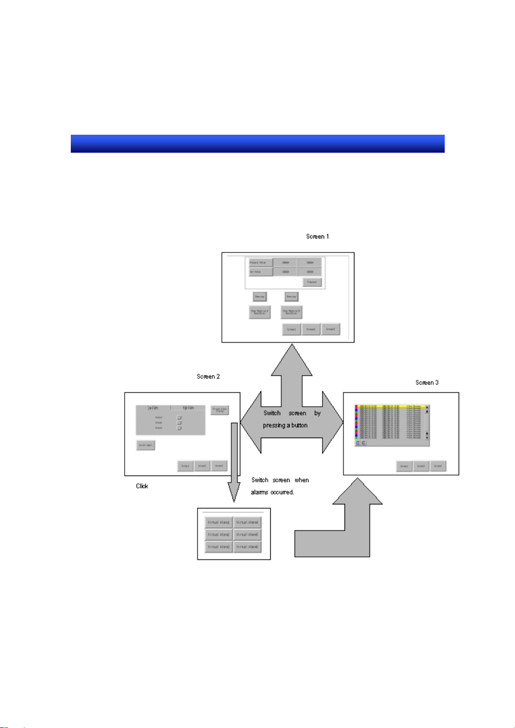
Screen1
This is a virtual operation screen. Instruction of operation start/stop and the
current value display of PLC are possible. Basic functional objects and fixed
objects are used in this screen. For details, refer to 4-1.
Screen2
This is a virtual alarm screen. When an error (alarm) occurs, correspondent
lamp will be turned ON.
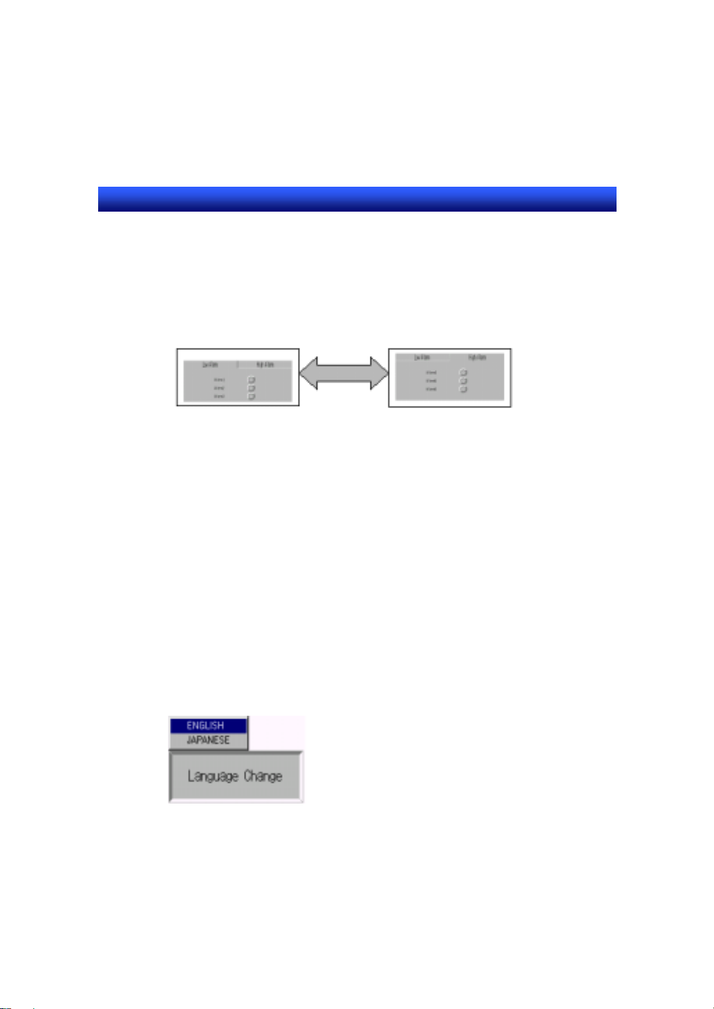
You can switch the label to other languages.
A frame object is used in this screen. When using a frame object, you can
switch a part of a screen by specifying an address. Here, display of the low
alarm list and the high alarm list can be switched. For details, refer to 6-2.
Screen3
This is a virtual alarm history screen. You can check the alarm histories, which
occurred in the past in a list format. When an alarm occurs, this screen will be
displayed automatically. For details, refer to 6-3.
Pop-up window screen
This screen will be displayed when you press the VIRTUAL ALARM OCCUR
button on screen2.
This screen has buttons, which cause virtual alarms. For details, refer to 6-4.
1 - 2
Page 9

Section2 Operation Flow
NS series Tutorial Manual
Section2 Operation Flow
The procedures to create sample screens are described in this section.
2-1 Operation Flow
・・・・・・・・・・・・・・・・・・・・・・・・・・・・・・・・・・・・・・・・
2 - 1
Page 10

Section2 Operation Flow
NS series Tutorial Manual
2-1 Operation Flow
Considering the contents
to be displayed on the
screen
|
Designing the screens
|
List the contents to be displayed on each screen
and investigate what behavior or process is to be
executed.
Design the each screen. (E.g. Configuration of
screens on which each display items are created,
common items to be displayed on multiple screens
(sheet screen) or screen switching method etc.)
Address allocation
Allocate addresses so that each function object can
work.
|
Creating each screen
Create each screen.
|
Checking the contents of
each screen
Use T est Function to check the movement of screen
switching behavior, function of each object, or
display contents.
|
Constructing the operation
Construct actual operation environment such as
connection to a PLC etc.
environment
|
System program/project data
Transfer the system data or project data which was
created with an NS-Designer to an NS hardware.
transfer to an NS hardware*
|
Checking the movement
Start up an NS hardware and check the movement
with a PLC.
of the entire system
* Installation of system program is needed only when the system in an NS
hardware is corrupted or when it should be replaced.
2 - 1
Page 11

Section3 Starting-up and Exiting the NS-Designer
NS series Tutorial Manual
Section3 Starting-up and Exiting the
NS-Designer
Before creating sample screens, the procedure for starting up and exiting the
NS-Designer is described here.
3-1 Starting up the NS-Desinger
3-2 Exiting the NS-Designer
・・・・・・・・・・・・・・・・・・・・・・・・・・・・・・・・
・・・・・・・・・・・・・・・・・・・・・・・・・・・
3 - 1
3 - 2
Page 12
Section3 Starting-up and Exiting the NS-Designer
NS series Tutorial Manual
3-1 Starting up the NS-Designer
1.Display the desktop screen of Windows NT or Windows 95/98/Me/2000/XP.
2.Select [Start] – [Programs] – [Omron] – [NS-Designer Ver.x] – [NS-Designer
Ver.x].
3.NS-Designer starts up.
3 - 1
Page 13

Section3 Starting-up and Exiting the NS-Designer
NS series Tutorial Manual
3-2 Exiting the NS-Designer
To exit the NS-Designer, use any of the operations shown below.
• In the menu, select [File] – [Exit].
• Click on button at the upper right corner in the main window.
• Double click the NS-Designer icon displayed at the upper left section in the main
window.
• Click the NS-Designer icon displayed at the upper left section in the main window ,
then select [Close] in the control menu box.
• Press F4 key while pressing down the Alt key.
If the currently opened project data is not saved yet, confirmation dialog will be
displayed.
After you exit the NS-Designer, the screen returns to the Windows screen.
3 - 2
Page 14

Section4 STEP1 Creating a Simple Screen
NS series Tutorial Manual
Section4 STEP1 Creating a Simple
Screen
This section describes the basic operation of NS-Designer including the
procedure to create new project/screen and the procedure to save project data.
4-1 Outline of the Screen to be Created in STEP1
4-2 Creating a New Project
4-3 System Setting
4-4 Host Registration
・・・・・・・・・・・・・・・・・・・・・・・・・・・・・・・・・・・・・・・
・・・・・・・・・・・・・・・・・・・・・・・・・・・・・・・・・・・・・
4-5 Screen Property Setting
4-6 Grid Setting
・・・・・・・・・・・・・・・・・・・・・・・・・・・・・・・・・・・・・・・・
4-7 Creating Screen1
4-8 Saving a Screen
4-9 Creating Sheet1
4-10 Applying a sheet
・・・・・・・・・・・・・・・・・・・・・・・・・・・・・・・・・・・
・・・・・・・・・・・・・・・・・・・・・・・・・・・・・・・・・・・・
・・・・・・・・・・・・・・・・・・・・・・・・・・・・・・・・・・・
・・・・・・・・・・・・・・・・・・・・・・・・・・・・・・・
・・・・・・・・・・・・・・・・・・・・・・・・・・・・・・
・・・・・・・・・・・・・・・・・・・・・・・・・・・・・・・・・・・
・・・・・・・・
4 - 1
4 - 3
4 - 7
4 - 8
4 - 9
4 - 10
4 - 11
4 - 20
4 - 21
4 - 24
Page 15
Section4 STEP1 Creating a Simple Screen
NS series Tutorial Manual
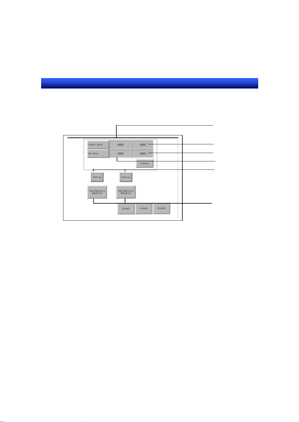
4-1 Outline of the Screen to be Created in STEP1
Operation Status
This section describes the outline of screen1 and sheet1.
Present Value(1)
Present Value(2)
Set Value(2)
Set Value(1)
Start/Stop button
Outline of screen1
Outline of screen1 is described below.
Function outline
1.Start/Stop button
Each time you press the button, it goes ON and OFF alternately.
2.Operation Status
“RUN” lamp turns ON when the Start/Stop button goes ON, and it turns OFF
when the Start/Stop button goes OFF.
3.Set Value (1)/(2) input/display Field
(a) Numeral value is displayed, or input from keypad.
(b) Set value (1) will be calculated and the result is displayed in set value (2).
This function is added in STEP4 using macro function.
4.Present value display field (1)/(2)
The value of PLC address is displayed in present value di splay field (1) and (2).
4 - 1
Page 16

Section4 STEP1 Creating a Simple Screen
NS series Tutorial Manual
Outline of sheet1
Sheet1 will be overlapped with other screens. Therefore, sheet1 itself will not
be displayed as an independent screen. Sheet1 will be overlapped with
screen1, 2 and 3 (screen2 and 3 will be created later).
Function outline
Screen switch button
When the button is pressed, the screen switches.
To screen1 To screen2 To screen3
When the sheet1 is overlapped with screen1, the screen will be as follows.
4 - 2
Page 17

Section4 STEP1 Creating a Simple Screen
NS series Tutorial Manual
4-2 Creating a New Project
Before creating screens, you need to create a project, which stores screens.
1. Create new project.
Select [File] – [New project].
2.Specify the PT model system version.
(1) Select NS12-TS0□(-V1).
(2) Select System Ver.4.0
(2) Click on [OK] button.
3.Select the screen creating procedure.
(1) Select [New Screen].
(2) Click on [OK] button.
4 - 3
Page 18
Section4 STEP1 Creating a Simple Screen
NS series Tutorial Manual
4.New screen opens.
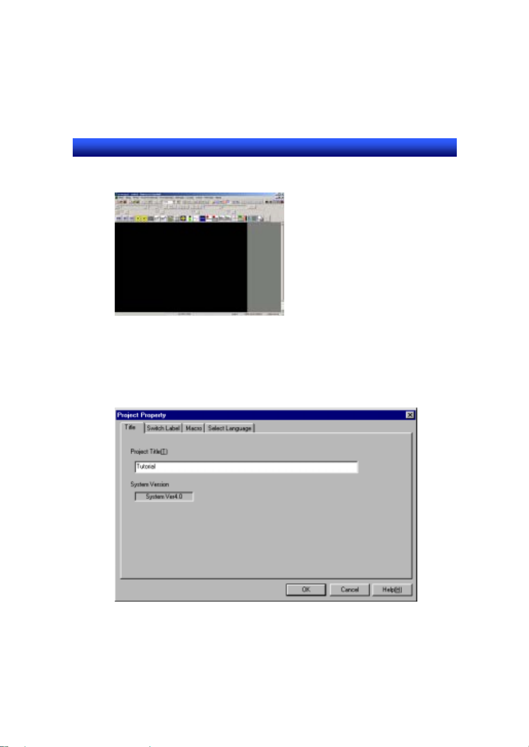
Make a parameter setting of a project.
1. Select - [Settings] - [Project properties].
2. Set a comment for a project.
(1) Click on [Title] tab.
(2) Input “Tutorial”.
4 - 4
Page 19
Section4 STEP1 Creating a Simple Screen
NS series Tutorial Manual
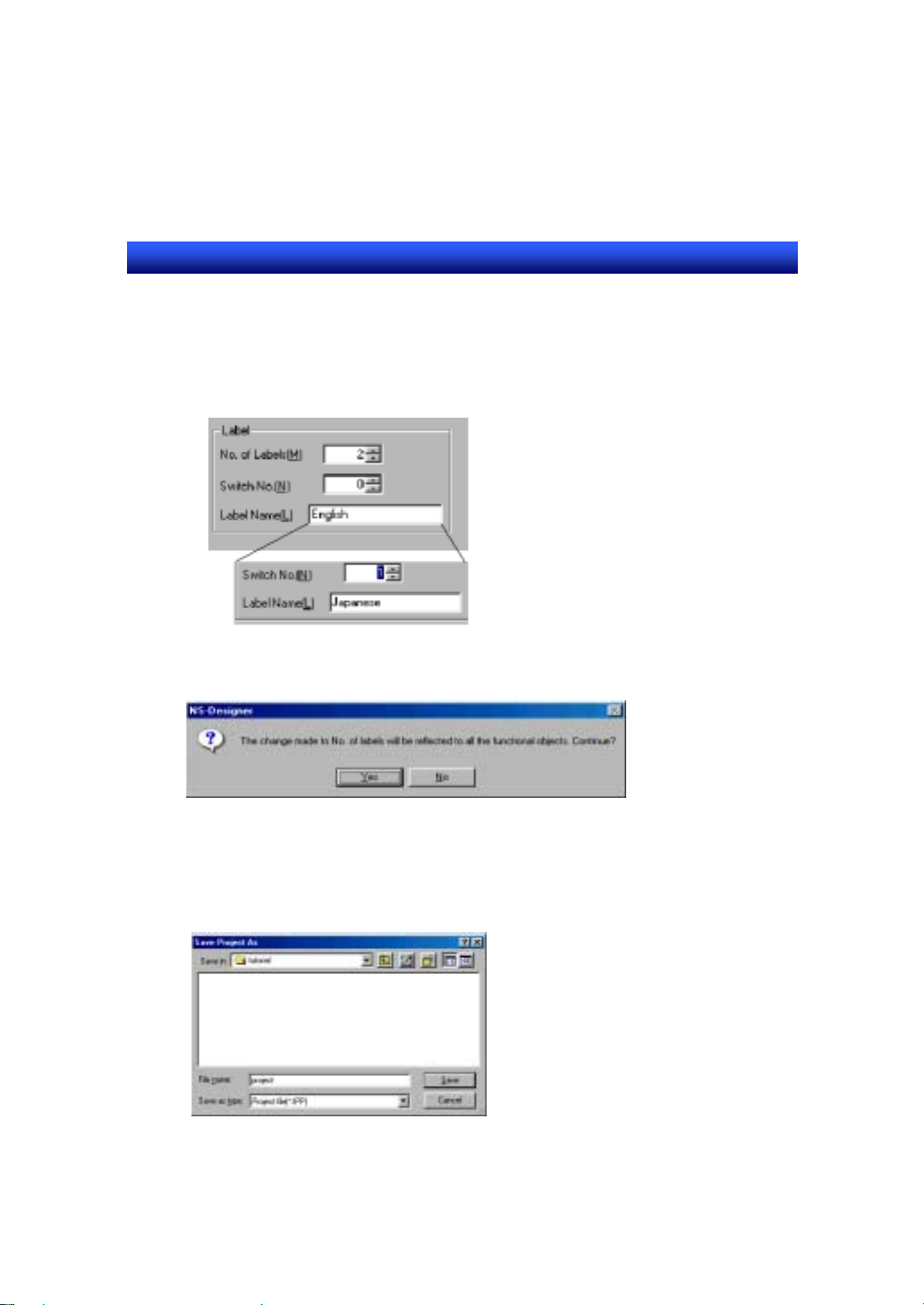
3. Set a number of labels.
(1) Click on of [Switch Label] tab.
(2) Set “2” for [No. of labels].
(3) Set “English” for [Label name] of [Switch No.0].
(4) Set “Japanese” for [Label name] of [Switch No.1].
4. Click on [OK] button.
Confirmation dialog will be displayed. Click on “Yes”.
5. Save a project.
Specify a folder and file name.
(1) Create the folder “Tutorial”.
(2) Input “Project” as a project name.
(3) Click on [Save] button.
Confirmation dialog will be displayed. Click on [Yes to all] button.
4 - 5
Page 20
Section4 STEP1 Creating a Simple Screen
NS series Tutorial Manual
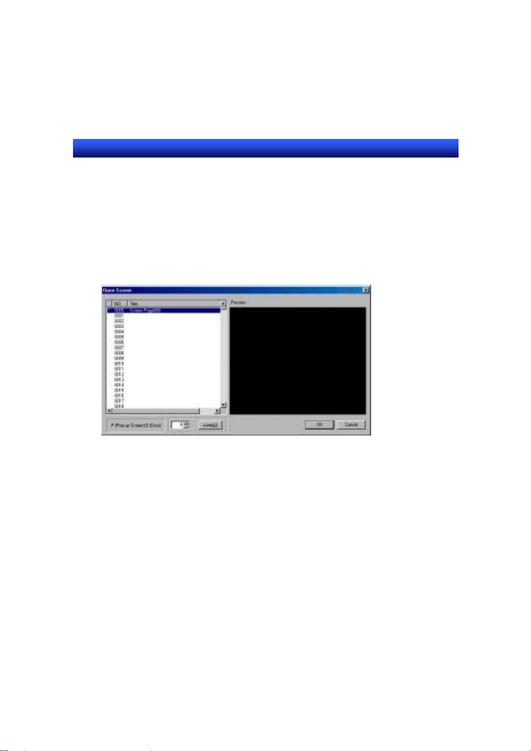
Opening a screen
The screen will be closed when saving a project. Open the screen again. Dialog
box to open a screen will be displayed automatically.
1.Select a screen No.
(1) Click on the screen page number [0000].
(2) Click on [OK] button.
2.Selected screen opens.
4 - 6
Page 21
Section4 STEP1 Creating a Simple Screen
NS series Tutorial Manual
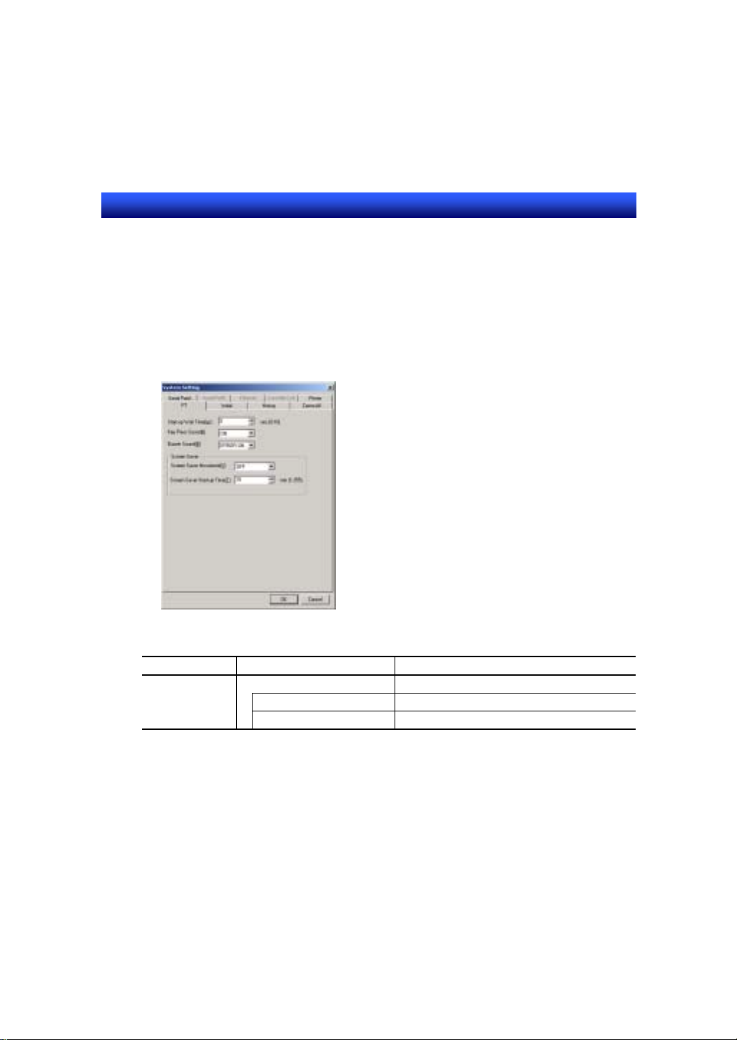
4-3 System Setting
The setting here assumes that you are going to use serial port A with NS
hardware.
1.Select [Settings]- [System Setting].
2. [System Setting] dialog is displayed.
3.Set as follows.
(For the settings not shown below, use default.)
Tab Item Contents
Initial System Memory
$SB allocation address $B1600
With the default setting, serial port A is used. Use the default setting here.
4. Click on [OK] button.
$SW allocation address $W1600
R
e
f
e
r
e
n
c
e
R
e
f
e
r
R
e
f
e
- To use Ethernet, refer to Section9 “Ethernet Connection”.
e
n
c
e
r
e
n
c
e
4 - 7
Page 22
Section4 STEP1 Creating a Simple Screen
NS series Tutorial Manual
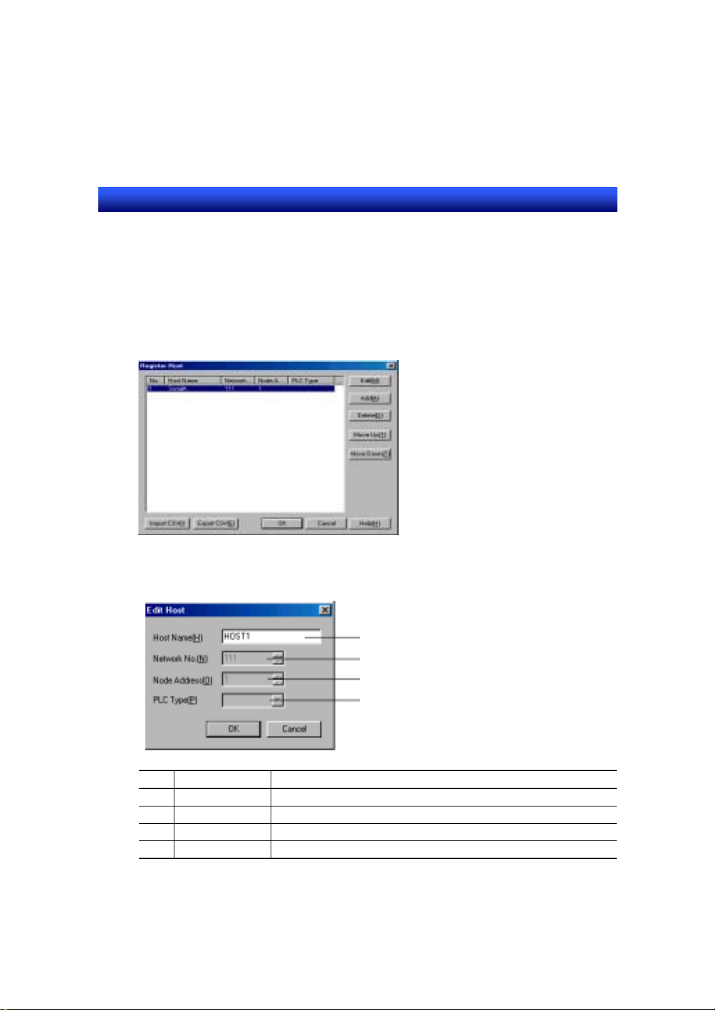
4-4 Host Registration
Register a host (PLC name of communication destination).
1. Select [Settings] – [Register Host].
2. Register a host.
Select the first line and click on [Edit].
With the default setting, “SerialA” is set. Change the host name.
3. Set as shown below.
1
2
3
4
No. Item Contents
1 Host Name HOST1(Default: Serial A)
2 Network No. 111(Fixed*)
3 Node Address 1 (Fixed*)
4 PLC Type No setting*
*: To use Serial Port A, setting is not possible.
4. Click on [OK] button and close the [Register Host] dialog.
4 - 8
Page 23
Section4 STEP1 Creating a Simple Screen
NS series Tutorial Manual
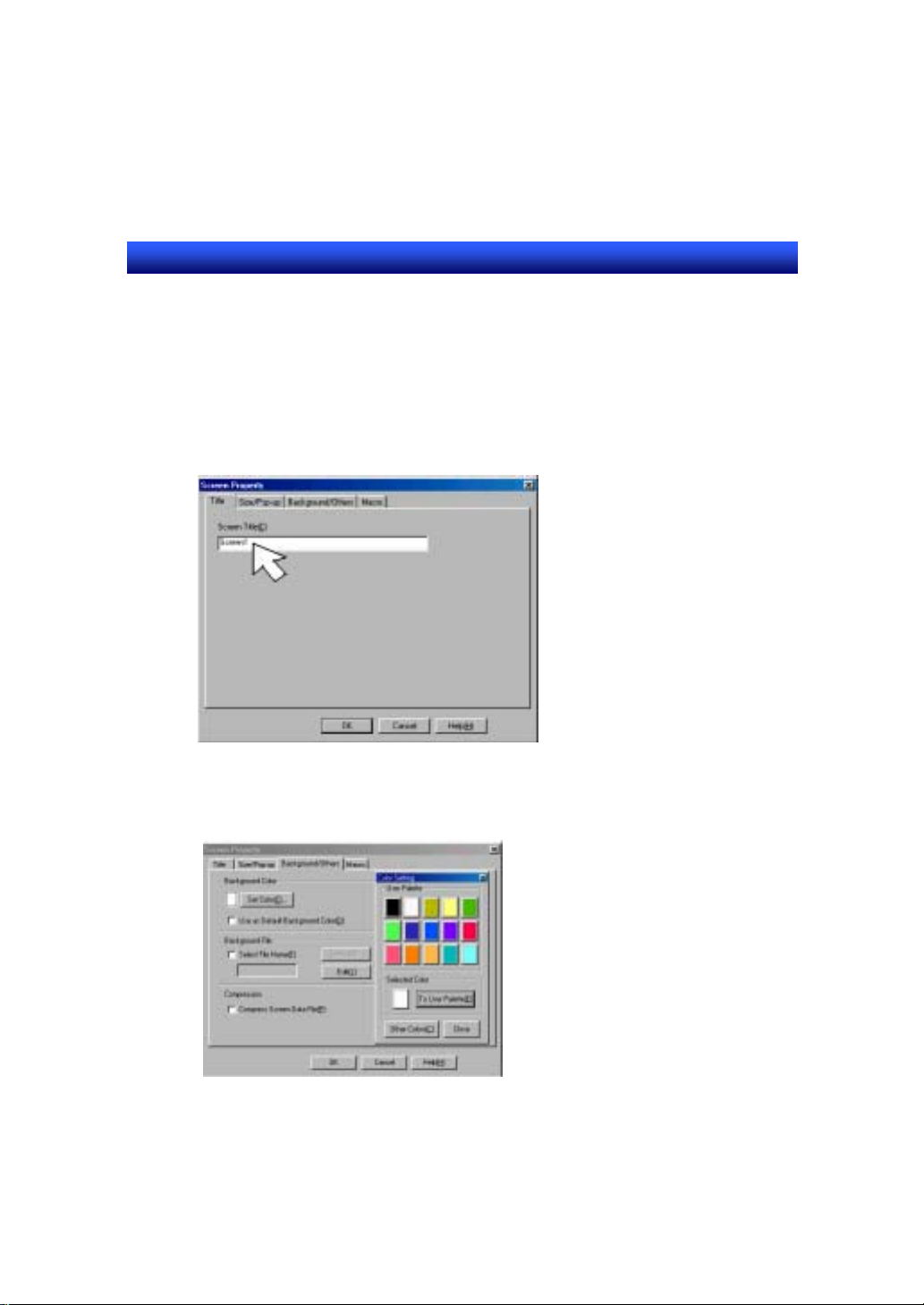
4-5 Screen Property Setting
The screen setting method is described in detail.
1. Select [Settings] – [Screen Properties].
2. Set a title.
(1) Select [Title] tab.
(2) Input “Screen1”.
3. Set a background color.
(1)Select [Background/Others] tab.
(2)Set “White” (color No: 015).
Use the default screen size.
Screen size: 800×600[Default]
4. Click on [OK] button.
4 - 9
Page 24
Section4 STEP1 Creating a Simple Screen
NS series Tutorial Manual
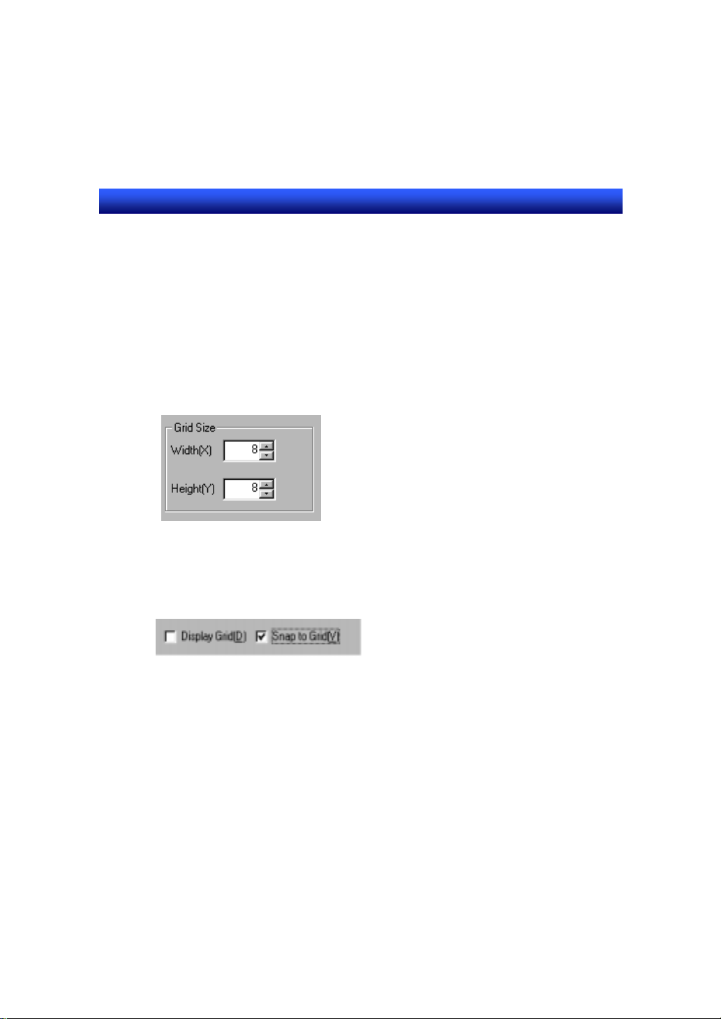
4-6 Grid Setting
Specify a grid before creating a screen. Once you set a grid, you can move an
object at fixed interval. So you do not have to adjust the position of an object
minutely.
1.Select [Layout] - [Grid].
2.Specify the grid space.
Set 8 for width and height.
3. Activate grid setting.
Check the [Snap to Grid] box.
T o display grid, check ON [Display Grid].
4. Click on [OK] button.
4 - 10
Page 25
Section4 STEP1 Creating a Simple Screen
NS series Tutorial Manual
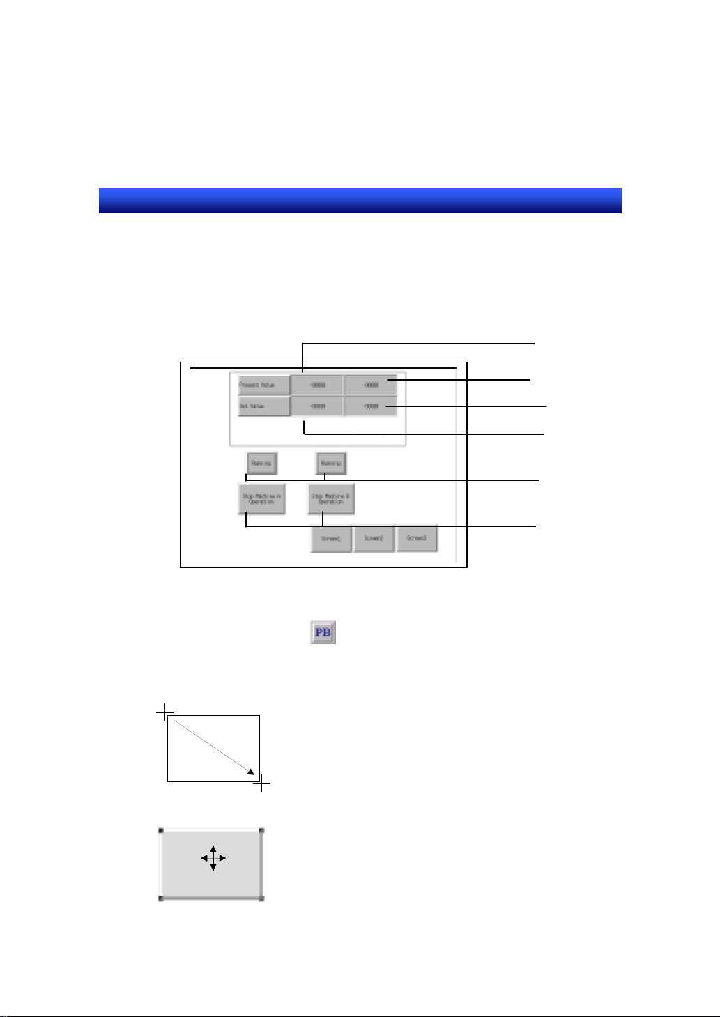
4-7 Creating Screen1
The procedures to create objects on the screen and set properties are
described.
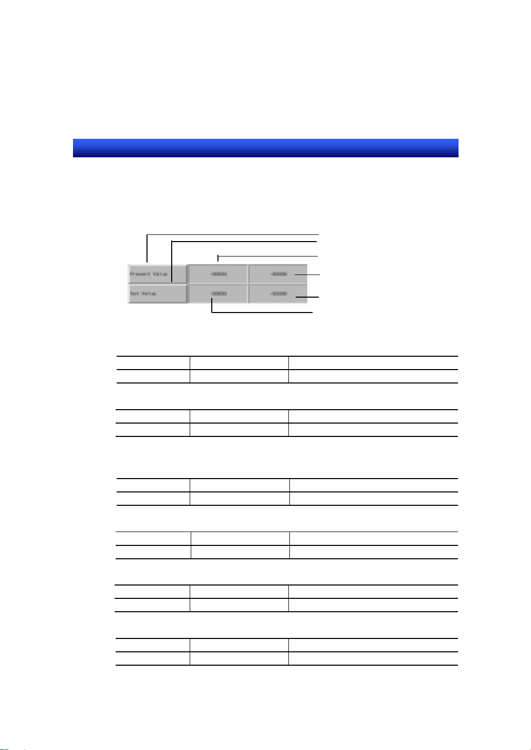
Present Value(1)
Present Value(2)
Set Value(2)
Set Value(1)
Operation Status
Start/Stop button
Creating functional objects
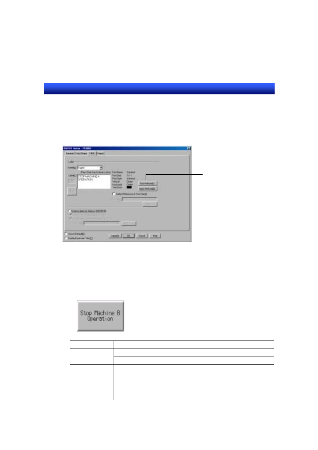
Create “Start/Stop Machine A Operation” button.
1.Click on [ON/OFF Button] from [Functional Objects] toolbar.
2.Create ON/OFF button on the screen.
(1) Click on a desired position on the screen with the “+” shaped mouse cursor.
(2) Drag the cursor until the object becomes to the desired size.
3. Open the property setting dialog box of ON/OFF button.
Place a cursor on the ON/OFF button and double-click on it.
Double-click
4 - 11
Page 26
Section4 STEP1 Creating a Simple Screen
NS series Tutorial Manual
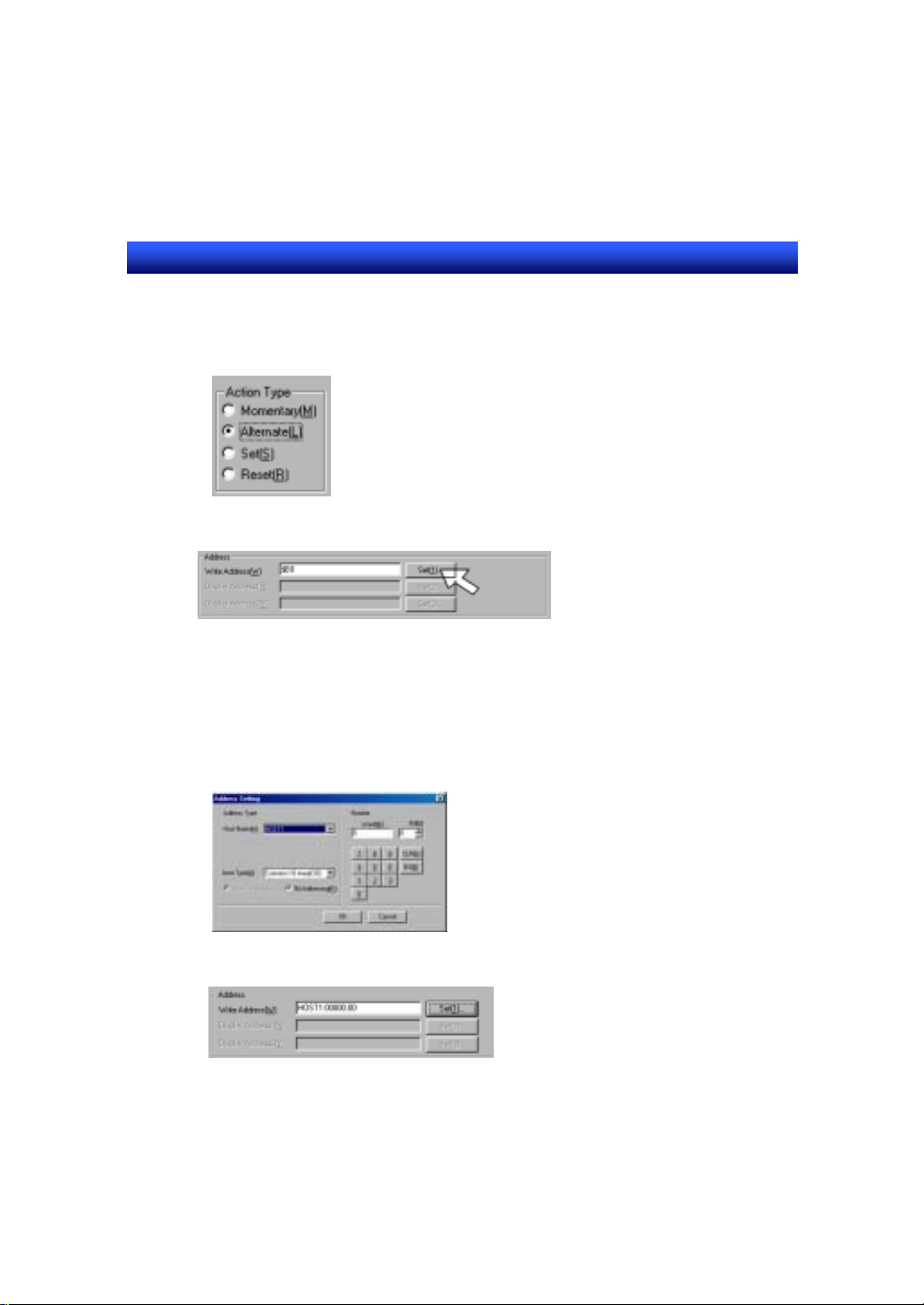
4. Choose Action Type
Select [Alternate]. When [Alternate] button is pressed, 1 and 0 are written to the specified
communication address alternately.
5. Input address from [Address Setting] dialog.
Click on [Set] button.
6. Set address.
Set CIO 00000.00.
(1) Set as shown below.
Host name: HOST1 (Hereafter, select HOST1 to set PLC address.)
Area Type : Select CIO, Bit Addressing
Word
Bit : 0
(2) Click on [OK] button.
: Input “0” using key button
7. ”HOST1:00000.00” is set in write address input field.
8. Set label for OFF status.
(1) Select [Label] tab.
(2) Input “Start Machine A Operation” as a label.
4 - 12
Page 27
Section4 STEP1 Creating a Simple Screen
NS series Tutorial Manual
9. Set label for ON status.
(1) Check ON “Switch Labels for Address ON/OFF” box.
(2) Check ON “Link with write address ON/OFF” box.
(3) Click on “ON/OFF” button.
(4) Input “Stop Machine A Operation” as a label.
10. Click on [OK] button.
Create the buttons shown below in the same manner.
*: The content in ( ) shows an object name to be used.
(1) Start/Stop Machine B operation button (ON/OFF button)
To change the next attribute,
click this button. Font size and
other setting can be changed.
Tab Item Contents
General Action type Alternate
Write address HOST1:00000.01
Label Switch labels for address ON/OFF Check ON
Label for OFF Start MachineB
operation
Label for ON Stop MachineB
operation
4 - 13
Page 28
Section4 STEP1 Creating a Simple Screen
NS series Tutorial Manual
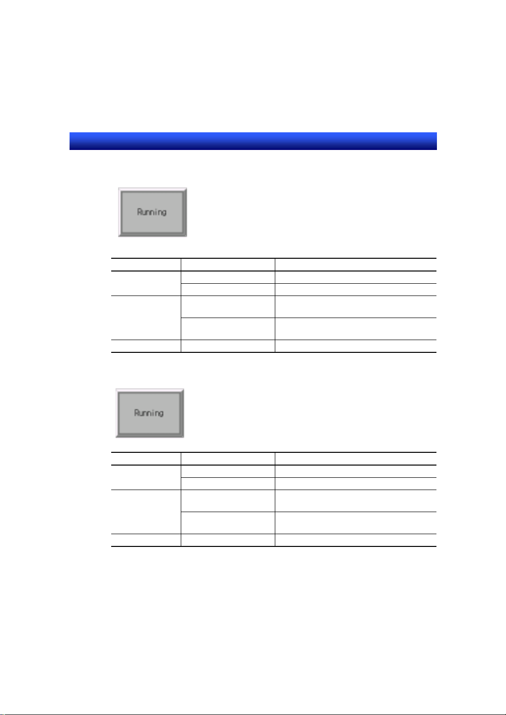
(2) Machine A running (bit lamp)
Tab Item Contents
General Lamp type Double-lined rectangle
Display address HOST1:00000.00
Color/Shape Color1 (Foreground color
Color2 (Foreground color
Label Label Running
(3) Machine B running (bit lamp)
Tab Item Contents
General Lamp type Double-lined rectangle
Display address HOST1:00000.00
Color/Shape Color1 (Foreground color
Color2 (Foreground color
Label Label Running
for OFF)
Grey (Color No: 007)
Yellow (Color NO: 014)
for ON)
Grey (Color No: 007)
for OFF)
Yellow (Color NO: 014)
for ON)
4 - 14
Page 29

Section4 STEP1 Creating a Simple Screen
NS series Tutorial Manual
Creating functional objects using a table
Create numeral display & input objects collectively (2x2, with 2 labels) using
“Table” function.
1. Click on [Table] from [Functional Objects] toolbar.
2. Create a table.
3. Open a property setting dialog of table.
Double-click on the area specified as a table.
Double-click
4. Select a functional object from a combo box.
Select “Numeral display&input”. (See the figure of 5)
5. Set Auto-allocation of communication address.
(1) Check ON “Allocate Addresses Automatically” box.
(2) Select “Horizontal” for allocate direction.
(3) Set “1” for Address Allocation Interval.
4 - 15
Page 30
Section4 STEP1 Creating a Simple Screen
NS series Tutorial Manual
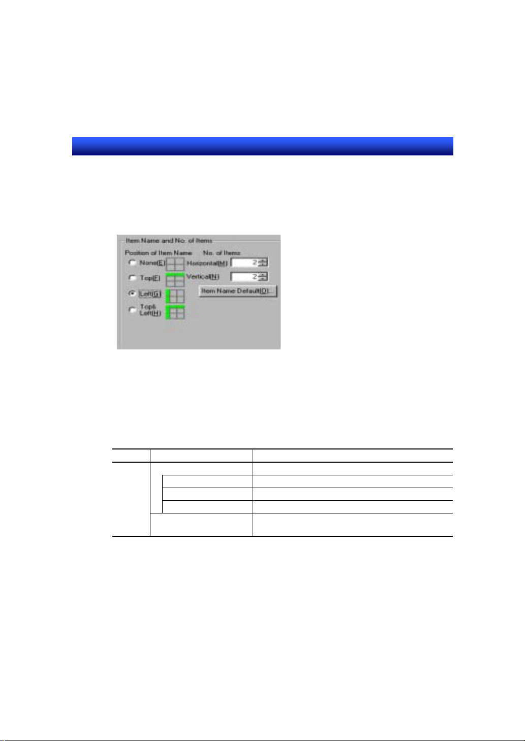
6. Set the number of rows and lines of table.
Set “2” for Horizontal and Vertical. (see the figure of 7)
7. Set the position of item name.
Select “Left”.
The property setting of a table is finished. Next, set the property setting of
numeral display & Input objects, which are displayed in a table collectively.
1. Click on [Functional object default] button in table setting dialog.
2. Set as shown below.
Tab Item Contents
General Numeral display type
Display type Decimal
Storage type INT(signed 1 word )
Format Integer: 5, Decimal: 0
Address HOST1:DM00000
3. Click on [OK] and close table setting dialog.
Specify a start address to be allocated.
4 - 16
Page 31
Section4 STEP1 Creating a Simple Screen
(4)
(6)
NS series Tutorial Manual
Set the property of each functional object in a table.
To open a property setting dialog of each object, double-click on the object.
Set the property of functional objects in a table as shown below.
(1)
(2)
(3)
(5)
(1) Item : Present value (label)
Tab Item Contents
Label Label Present value
(2) Item: Set value (label)
Tab Item Contents
Label Label Set value
(3) Present value1 (numeral display & input)
Check ON “Display expansion tabs” to display “Control flag” tab.
Tab Item Contents
Control Flag Input Disable
(4) Present value2 (numeral display & input)
Tab Item Contents
Control Flag Input Disable
(5) Set value1 (numeral display & input)
Tab Item Contents
General Address PT memory, $W0
(6) Set value2 (numeral display & input)
Tab Item Contents
General Address PT memory, $W1
4 - 17
Page 32

Section4 STEP1 Creating a Simple Screen
NS series Tutorial Manual
R
e
f
e
r
e
n
c
e
R
e
f
e
r
R
e
f
e
r
The size of functional objects in a table can be changed by line or row unit.
1. Place a cursor on the vertical/horizontal border of functional objects. The
shape of the cursor changes as follows.
e
n
c
e
e
n
c
e
2. Drag the cursor in the indicated direction to modify the size.
It is also possible to change the size of a table. When the table size is changed,
the functional objects in a table will be also resized.
1. Place a cursor on the outer frame of a table. The shape of the cursor changes
as follows.
2. Drag the cursor in the indicated direction to modify the size.
4 - 18
Page 33

Section4 STEP1 Creating a Simple Screen
NS series Tutorial Manual
Creating a fixed object
Create a rectangle which encloses the table.
1. Click on [Rectangle] from [Fixed Objects] toolbar.
2. Draw a rectangle.
(1) Click on a desired position on the screen with the “+” shaped mouse cursor.
(2) Drag the cursor until the object becomes to the desired size.
3. While selecting a rectangle, make a right click. Select [Order] – [Send To
Back] from pop-up menu.
4. Set a property of rectangle.
(1) Place a cursor on a rectangle and double click on it.
(2) Set as shown below.
Tab Item Contents
Tiling No tiling Check ON
Line Color Black (Color No: 000)
5. Click on [OK] button.
4 - 19
Page 34

Section4 STEP1 Creating a Simple Screen
NS series Tutorial Manual
4-8 Saving a Screen
Creation of screen1 is finished. Save screen1.
1.Click on [Save screen] from [Standard] toolbar.
4 - 20
Page 35

Section4 STEP1 Creating a Simple Screen
NS series Tutorial Manual
4-9 Creating Sheet1
Create a sheet, which is used to overlap with screen1, 2 and 3.
Creating new sheet
1. Select [File] – [Open Sheet].
2. Specify a sheet number.
(1)Select “0000”.
(2)Click on [OK] button.
3. Confirmation dialog is displayed.
Click on [Yes] button.
4 - 21
Page 36

Section4 STEP1 Creating a Simple Screen
NS series Tutorial Manual
4. Set a screen property. ([Settings] – [Screen Properties])
(1)Set as shown below.
Tab Item Contents
Title Screen Title Sheet1
Background/
Others
Use the default screen size.
Screen size: 800x600(Default)
(2)Click on [OK] button.
Background
Color
White (Color No: 015)
5. Sheet opens.
4 - 22
Page 37
Section4 STEP1 Creating a Simple Screen
NS series Tutorial Manual
Creating an object
Create the following objects on the sheet.
(1) Screen switch button to screen1 (command button)
Tab Item Contents
General Function 1.Switch screen
Label Label Screen1
(2) Screen switch button to screen2 (command button)
Tab Item Contents
General Function 1.Switch screen
Label Label Screen2
(3) Screen switch button to screen3 (command button)
Tab Item Contents
General Function 1.Switch screen
Label Label Screen3
Saving a sheet
2.Select [Specified screen]
3.Click on [Select] button and choose “0000:
Screen1”.
2.Select [Specified screen]
3.Click on [Select] button and choose “0001”.
2.Select [Specified screen]
3.Click on [Select] button and choose “0002”.
Creation of sheet1 is finished. Save sheet1.
1. Click on [Save Screen] from [Standard] toolbar.
4 - 23
Page 38

Section4 STEP1 Creating a Simple Screen
NS series Tutorial Manual
4-10 Applying a Sheet
Apply a sheet to other screens.
1. Select [File] – [Apply Sheet].
2. Apply sheet1 to screen1.
(1)Select “0000 Screen1”.
(2)Check ON “0” Selection of sheet1
(3)Click on [Apply] button.
3. Sheet1 is applied to screen1 and is displayed in a preview window.
4. Apply sheet1 to “0001” (it will be created later as screen2) and “0002” (it will
be created later as screen3) in the same manner.
5. Click on [OK] button.
4 - 24
Page 39

Section5 STEP2 Debug
NS series Tutorial Manual
Section5 STEP2 Debug
This section describes the procedure to debug the project you have created in
STEP1 on a personal computer.
5-1 Test Function
5-2 Test Tool
・・・・・・・・・・・・・・・・・・・・・・・・・・・・・・・・・・・・・・・・・・・・・・・
5-3 Exiting a Test
・・・・・・・・・・・・・・・・・・・・・・・・・・・・・・・・・・・・・・・・・・
・・・・・・・・・・・・・・・・・・・・・・・・・・・・・・・・・・・・・・・・・・
5 - 1
5 - 3
5 - 5
Page 40

Section5 STEP2 Debug
NS series Tutorial Manual
5-1 Test Function
NS-Designer has a test function. If you use this function, you can check the
movement of project data on a personal computer without connecting a PLC.
Check the movement by operating registered functional objects with a test
function.
Starting a test
Before executing a test, set the condition for start-up of a test.
1. Select screen1 from [Window] menu to bring this screen to front.
2. Select [Tools] - [Test].
3. Confirmation dialog to save project data is displayed. Press [Yes] button.
4. Set the condition for start-up of a test.
Check ON “Start test from the current screen”. (Screen1 will be displayed in a test screen.)
5. Start a test.
Click on [Start] button.
5 - 1
Page 41

Section5 STEP2 Debug
NS series Tutorial Manual
Executing a test
Test screen and test tool are started up.
1. Test screen is displayed in a window.
(Default size: 800dot×600dot)
Test Tool
2. Check the movement of objects by clicking a button or input numeral value to
a numeral display&input.
R
e
f
e
r
e
n
c
e
R
e
f
e
r
R
e
f
e
How to switch test screen to a screen with a title bar and menu bar:
Double-click on a screen where no object is registered, screen displa y styl e will
be changed to [With title bar and menu bar]->[With menu bar]->[With Title
bar]-->[Full screen].
When a test tool is displayed at the center of a screen, confirmation dialog to exit
a test may be hidden by a test tool. When a confirmation dialog is not found,
change the display position of a test tool to check if the dialog box is hidden.
e
n
c
e
r
e
n
c
e
5 - 2
Test Screen
Page 42
Section5 STEP2 Debug
NS series Tutorial Manual
5-2 Test Tool
Check the movement of functional objects by changing the value of address
with a test tool.
Check the online movement of functional objects by changing the address to
ON and OFF or writing a value.
1. Select the address you want to change value and double-click on it.
Select HOST1: 00000.00 and double-click on it.
2. Turn ON HOST1:00000.00.
Click on [SET] button.
Double-click
5 - 3
Page 43
Section5 STEP2 Debug
NS series Tutorial Manual
3. When the HOST1:00000.00 is turned ON, the display of a button change s as
follows. At the same time, the correspondednt lamp is lit.
Click on [RESET] button in [Change Val] dialog.
5. Write value to $W0.
(1)Select $W0 and double-click on it.
(2)Input “123” to [Change Value] dialog.
(3)Click on [OK] button.
6. ”123” is displayed in Set Value1.
5 - 4
Page 44

Section5 STEP2 Debug
NS series Tutorial Manual
5-3 Exiting a Test
Exit a test.
1.Click on button on a title bar.
2.Confirmation dialog to exit a test is displayed.
Click on [Yes] button.
R
e
f
e
r
e
n
c
e
R
e
f
e
R
e
f
e
r
e
n
c
e
r
e
n
c
e
Each time you double-click on a screen where no object is registered, window
style changes. When a menu bar is displayed, you can exit a test by selecting
[Quit] from [File] menu.
1. T o display a menu bar , ma ke a double-click three times. Window
style changes to [No title bar]->[Full screen]->[With title bar and
menu bar].
2.Display a menu bar and select [Quit] from [File] menu.
3.Confirmation dialog to exit a test is displayed. Click on [Yes] button
5 - 5
Page 45

Section6 STEP3 Useful Functions
NS series Tutorial Manual
Section6 STEP3 Useful Functions
This section describes the useful functions of NS-Designer. It is assumed that
you have basic knowledge of objects and the operation method of
NS-Designer.
6-1 Outline of Screens to be Created in STEP3
6-2 Creating Screen2
6-3 Creating Screen3
6-4 Creating a Pop-up Window Screen
・・・・・・・・・・・・・・・・・・・・・・・・・・・・・・・・・・・・・・
・・・・・・・・・・・・・・・・・・・・・・・・・・・・・・・・・・・・
・・・・・・・・・・・・・・・・・・・
・・・・・・・・・・・・
6 - 1
6 - 5
6 - 22
6 - 23
Page 46
Section6 STEP3 Useful Functions
NS series Tutorial Manual
6-1 Outline of Screens to be Created in STEP3
The outline of a screen2, 3 and a pop-up window screen which will be created
in STEP3 is shown below.
Outline of screen2
Outline of screen2 is shown below.
1.Alarm Display
3.Virtual Alarm
Display Button
2.Switch Label Button
Sheet Object
R
e
f
e
r
e
n
c
e
R
e
f
e
r
R
e
f
e
- If you switch frame page frequently, update of communication will be delayed.
e
n
c
e
r
e
n
c
e
6 - 1
Page 47
Section6 STEP3 Useful Functions
NS series Tutorial Manual
Function outline
1. Alarm display
Press the tab area to switch display.
Low alarm display
When you press any of the virtual alarm occur button1-3 in a pop-up window
screen, correspondent alarm lamp goes ON. When the alarm is cancelled,
correspondent lamp goes OFF.
High alarm display
When you press any of the virtual alarm occur button4-6 in a po p-up window
screen, correspondent alarm lamp goes ON. When the alarm is cancelled,
correspondent lamp goes OFF.
2. Switch label button
When you press this button, a pop-up menu to switch the language of label
(English/Japanese) is displayed. Selected label type is applied.
3. Virtual alarm display button
When you press this button, a pop-up window screen which has virtual
alarm display buttons is displayed.
6 - 2
Page 48

Section6 STEP3 Useful Functions
NS series Tutorial Manual
Outline of screen3
Outline of screen3 is shown below.
When an alarm occurs, this screen will be displayed automatically.
Function Outline
1. Virtual alarm occurrence history
Virtual alarm history which is occurred/cancelled on a pop-up window screen
is displayed.
Sheet Object
6 - 3
Page 49

Section6 STEP3 Useful Functions
NS series Tutorial Manual
Outline of a pop-up screen
Outline of a pop-up screen is shown below.
This screen is displayed when you press virtual alarm display button in
screen2.
Function outline
1. Virtual alarm occurrence button 1 to 6
Each time you press the button, each virtual alarm will be ON and OFF
alternately.
6 - 4
Page 50

Section6 STEP3 Useful Functions
NS series Tutorial Manual
6-2 Creating Screen2
Creating a new screen
1. Select [New screen] from [Standard] toolbar.
2. Set the screen property as shown below.
Tab Item Contents
Title Screen Title Screen2
Background/
Others
Use the default screen size.
Screen size: 800x600(Default)
Alarm/Event setting
Set the contents to be displayed as an alarm.
1. Select [Settings] - [Alarm/Event].
2. Register an alarm.
Click on [Add] button.
Background
color
White (Color No: 015)
3. Input alarm message.
Input “Alarm 1 occur” in [Message].
6 - 5
Page 51

Section6 STEP3 Useful Functions
NS series Tutorial Manual
4. Select display type.
Choose [Low alarm] for [Display type].
5. Set address.
Set “HOST1:00001.00” as an address.
When HOST1:00001.00 goes ON, the alarm is detected.
6. Set the screen to be displayed when an alarm occurs.
(1) Check ON “Switch screen when address ON”.
(2) Click on [Set (3)] button and select “0002” screen.
7. Click on [OK] button.
Set the following alarms in the same manner.
No. Message Display
type
2 Alarm2 occur Low alarm HOST1:00001.01 Check ON 0002
3 Alarm3 occur Low alarm HOST1:00001.02 Check ON 0002
4 Alarm4 occur High alarm HOST1:00001.03 Check ON 0002
5 Alarm5 occur High alarm HOST1:00001.04 Check ON 0002
6 Alarm6 occur High alarm HOST1:00001.05 Check ON 0002
Address Switch screen when
address ON
6 - 6
Switch
screen No.
Page 52

Section6 STEP3 Useful Functions
NS series Tutorial Manual
8. With the default setting, it is not possible to switch to other screen from the
specified screen unless the alarm is cancelled.
Change the setting so that the screen switches only the moment when an
alarm occurred.
Click on [Parameter] button.
9. Click ”Rise trigger detection” and press [OK] button.
10. Click on [OK] in [Alarm/Event Setting] dialog.
6 - 7
Page 53
Section6 STEP3 Useful Functions
NS series Tutorial Manual
Creating a frame object
Create a frame object to switch the low alarm screen and the high alarm screen.
With a frame object, specified area can be switched.
1. Create a frame object.
Click on [Frame] from [Functional objects] toolbar and place it on the screen.
2. Set a frame property.
While selecting a frame, choose [Setting] - [Object Properties].
3. Set the number of frame pages.
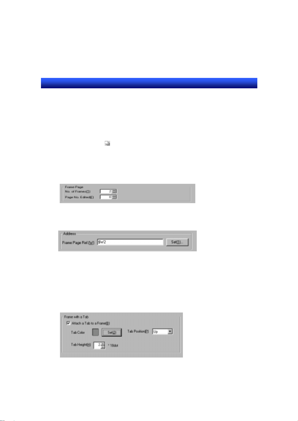
Set 2 for [No. of Frames].
4. Set the address.
Set “$W2” for [Frame Page Ref. ]. Frame page will be switched in accordance with the change
of value in $W2.
5. Set a tab which is used to switch a frame page on NS hardware.
(1) Check ON ”Attach a Tab to a Frame”.
(2) Set as shown below.
Tab Color: Gray (Color No: 007)
Tab Position: Up
Tab Height: 2
6 - 8
Page 54

Section6 STEP3 Useful Functions
NS series Tutorial Manual
6. Click on [OK] button.
7. A frame is created.
6 - 9
Page 55

Section6 STEP3 Useful Functions
NS series Tutorial Manual
Editing a frame page
To create objects inside a frame, enter the frame edit mode.
1. Double-click inside a frame.
2. Frame enters the edit mode, objects outside a frame will be invisible.
3. Click on [Previous frame page] or [Next frame page] to switch
the frame page to be edited.
4. To return to the normal edit mode, click the area outside of a frame.
6 - 10
Page 56

Section6 STEP3 Useful Functions
NS series Tutorial Manual
Creating a frame tab name
Create a title of frame tab using a text object. If a text is created in frame edit
mode, tab titles which are not in active statuses will be invisible on NS hardware.
Therefore, create tab titles in normal edit mode.
1. Click on [Text] from toolbar and paste a label so that it overlaps with the
frame tab position.
(1)
(2)
Reference
When a message to inform you that you can not create an object overlapping on the other
objects is displayed, cancel this restriction by following the procedure below.
1.Select [Options] from [Tools] menu.
2.Unmark the check box for “Prohibit functional objects from
overlapping” in [Edit/Disp] tab.
6 - 11
Page 57

Section6 STEP3 Useful Functions
NS series Tutorial Manual
2. Set the property of each text.
Double-click on the each text to display property setting di alog. Set each tab
as follows.
(1) Low alarm display (Text)
Tab Item Contents
Backgrou
nd
Label Label
English LOW ALARM
Japanese Keido alarm hyouji
Frame Three-dimensional
Draw Border Check OFF
(2) High alarm display (Text)
Tab Item Contents
Background Tile background Check OFF
Tile background Check OFF
Frame
After setting English label, select “Japanese”
from [Switch] combo box in [label] tab and input
label.
Check OFF
Label Label
English HIGH ALARM
Japanese Judo alarm hyouji
After setting English label, select “Japanese”
from [Switch] combo box in [label] tab and input
label.
Frame Three-dimensional
Check OFF
Frame
Draw Border Check OFF
6 - 12
Page 58
Section6 STEP3 Useful Functions
NS series Tutorial Manual
Creating function objects on each frame
Create functional objects on each frame.
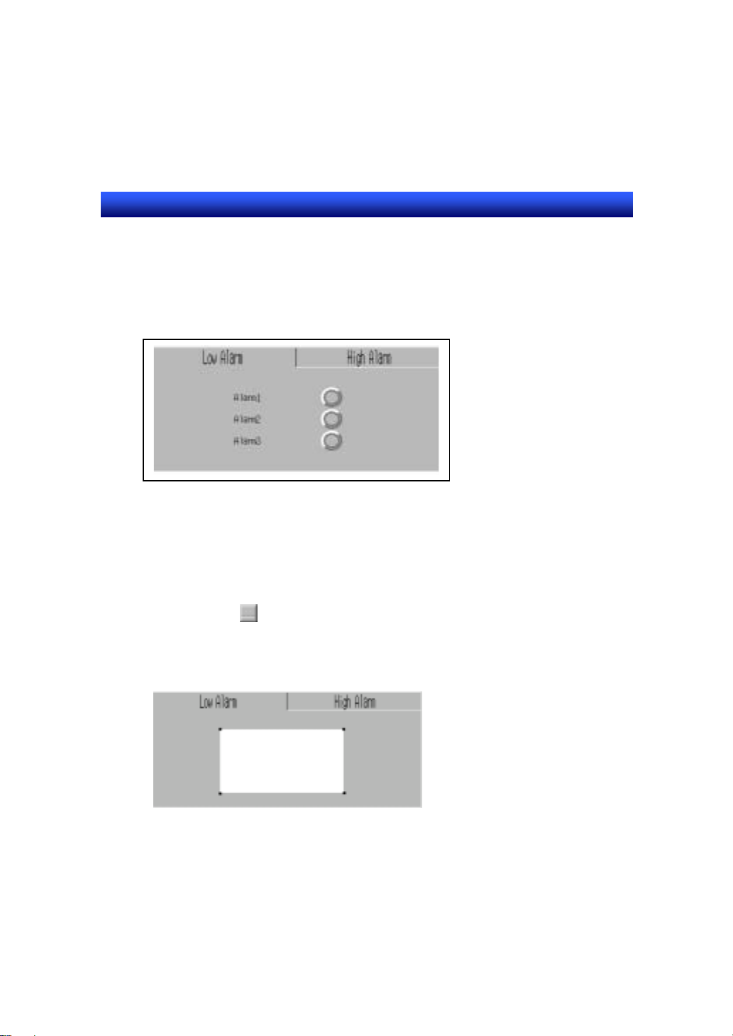
Low alarm display
1. Enter the frame edit mode.
Double-click on a frame.
2. Display low alarm display (frame page No: 0).
3. Paste a table object.
Click on [Table] from [Functional Objects] toolbar and place a table object.
6 - 13
Page 59
Section6 STEP3 Useful Functions
NS series Tutorial Manual
4. Set the table property as shown below.
Item Contents
Table type Bit lamp
Allocate Addresses Automatically Check ON
Direction Vertical
Address Allocation Interval 1
Position of item name Left
No. of items
Horizontal 1
Vertical 3
5. Click on [Functional object default] button and set as shown below.
Tab Item Contents
General Display address HOST1:00001.00
Lamp type Double-lined circle
6. Click on [OK] button to close [Bit lamp] dialog.
7. Click on [OK] button to close [Table setting] dialog.
8. Set the item name (text) of a table as shown below.
Double-click on an object to set each property.
(Settings not shown below do not have to be changed.)
(1) Alarm1
Tab Item Contents
label English ALARM 1
Text attribute
Horizontal
Japanese Ala-mu 1
Text attribute
Vertical
Backgro
und
Frame Three-dimensional
Draw Border Check OFF
position
position
Tile background Check OFF
frame
Center
Center
Check OFF
6 - 14
Page 60
Section6 STEP3 Useful Functions
NS series Tutorial Manual
(2) Alarm2
Tab Item Contents
label English ALARM 2
Text attribute
(3) Alarm3
Horizontal
Japanese Ala-mu 2
Text attribute
Horizontal
Backgro
und
Frame Three-dimensional
Draw Border Check OFF
Tab Item Contents
label English ALARM 3
Text attribute
Horizontal
Japanese Ala-mu 3
Text attribute
Horizontal
Backgro
und
Frame Three-dimensional
Draw Border Check OFF
position
position
Tile background Check OFF
frame
position
position
Tile background Check OFF
frame
Center
Center
Check OFF
Center
Center
Check OFF
6 - 15
Page 61
Section6 STEP3 Useful Functions
NS series Tutorial Manual
R
e
f
e
r
e
n
c
e
R
e
f
e
r
R
e
f
e
You can apply text attributes (font name, size, colors etc.) to other label. When
you click on [Apply attribute] button, [Apply attribute] dialog is displa yed. Check
ON the attributes to be applied and click on [OK] button.
Right after you crate a table, the size of each functional objects inside a tab le is
automatically adjusted so that they will be the same size. Therefore, the bit
lamps may be an oval shape depending on the table size. If you want to change
it to perfect circle shape, place a cursor on the vertical/horizontal side of bit
lamps and drag it.
For details of changing a table size, refer to P4-18.
e
n
c
e
r
e
n
c
e
Place a cursor on
the left edge of
bit lamps and
drag it to the right
side.
6 - 16
Page 62
Section6 STEP3 Useful Functions
NS series Tutorial Manual
High alarm display
Reuse the table object which is created in low alarm display page using copy
function and offset address function.
The operation procedure and setting contents are shown below.
1. After entering the frame edit mode, select a table in low alarm display page
by dragging around the table area.
2. Select [Copy] from [Edit] menu.
3. Click on [Next frame page] from [operation] toolbar to switch to high
alarm display page.
4. Select [Offset Paste] from [Edit] menu.
6 - 17
Page 63
Section6 STEP3 Useful Functions
NS series Tutorial Manual
5. Input “3” for [Offset] and click on [OK].
Addresses from HOST1:00001.03 to HOST1:00001.05 are allocated to pasted bit lamps.
6. Set the item name (Text) of a table as shown below.
(Settings not shown below do not have to be changed.)
It is also possible to set the labels of multiple functional objects collectively.
For details, refer to “MEMO”.
(1) Alarm1
Tab Item Contents
Label Label
English ALARM 4
Japanese Ala-mu 4
(2) Alarm2
Tab Item Contents
Label Label
English ALARM 5
Japanese Ala-mu 5
(3) Alarm3
Tab Item Contents
Label Label
English ALARM 6
Japanese Ala-mu 6
6 - 18
Page 64

Section6 STEP3 Useful Functions
NS series Tutorial Manual
R
e
f
e
r
e
n
c
e
R
e
f
e
r
R
e
f
e
How to set the labels of multiple functional objects?
It is possible to set the label collectively if the selected object type is the same.
Addresses and comments can be also edited.
E.g. The procedure to set labels of high alarm display collectively.
1. Enter the frame edit mode and select the item name (Text) at the top.
2. Select [Edit] – [Select all] – [Same functional object type].
3. Select [Settings] – [Change Settings at Once].
4. [Change Settings at Once] dialog is displayed.
5. Double-click on each cell and input label.
6. When the setting is finished, click on [OK] button.
For details of the setting, refer to NS-Designer operation manual “5-10 Setting
multiple functional objects”.
e
n
c
e
r
e
n
c
e
Creating switch label button
Create a word button which changes the label from English to Japanese,
or from Japanese to English.
The label No. currently used is stored in system memory $SW10.
When $SW10 is 0, English label is displayed, and when it is 1, Japanese
label is displayed.
6 - 19
Page 65

Section6 STEP3 Useful Functions
NS series Tutorial Manual
Word button
Tab Item Contents
General Action Type Select “Display Pop-up Menu ”.
Pop-up menu
(1) Click on [Edit Menu] button.
(2) [Pop-up Menu List] dialog is
displayed.
(3) Click on [Add] button and set as
follows.
Menu Name Set Value
English 0
Japanese 1
(4) Create a pop-up menu used when
label is Japanese.
Select Japanese from [Switch]
combo box.
(5) Select a line and click on [Edit]
button. Set as follows.
Menu Name Set Value
Eigo 0
Nihongo 1
Address (Write address) $SW10
Label Label
English Language Change
Japanese Meiban kirikae
6 - 20
Page 66

Section6 STEP3 Useful Functions
NS series Tutorial Manual
Set the virtual alarm display button as shown below.
Virtual alarm display button (command button)
Tab Item Contents
General Function 1. Switch screen
Label Label
English Virtual Alarm Display
Japanese Kasou alarm display
2. Select “To specified screen”.
3. Click on [OK] button and specify “0003”.
6 - 21
Page 67

Section6 STEP3 Useful Functions
NS series Tutorial Manual
6-3 Creating Screen3
Create a new screen and set the property as shown below.
Tab Item Contents
Title Screen title Screen3
Background/Oth
ers
Use the default screen size.
Screen size: 800x600(Default)
Creating an object
Create the following object on screen3.
Alarm history (Alarm/Event summary &history)
Background
color
White (Color No: 015)
Tab Item Contents
General Display data Alarm history
Date &Time Display Format Check ON
Date yyyy/mm/dd
Time hh:mm
Icon Icons
From new date &time Check ON
From old date &time Check ON
Icon size
Width 44
Height 44
6 - 22
Page 68

Section6 STEP3 Useful Functions
NS series Tutorial Manual
6-4 Creating a Pop-up Window Screen
Create a new screen.
To create a pop-up window screen which is displayed on the other screen, set
the screen properties as follows.
Tab Item Contents
Title Screen title Pop-up window screen
Size/Pop-up
Background/Oth
ers
Creating an object
Create an object shown below on a pop-up window screen.
Screen size Width: 320, Height: 240
Use as pop-up
screen
Pop-up Screen
Display Position
Background
color
Check ON
Bottom Left of Screen
White (Color No: 015)
Virtual alarm occur button from 1 to 6.
1. Use Table function to create them collectively.
2. Set the table property as follows.
Item Contents
Table type ON/OFF button
Allocate Addresses Automatically Check ON
Direction Vertical
Address Allocation Interval 1
Position of Item name None
No. of items
Horizontal 2
Vertical 3
6 - 23
Page 69

Section6 STEP3 Useful Functions
NS series Tutorial Manual
3. Click on [Function object default] button and set as follows.
Tab Item Contents
General Action Type Alternate
Write address HOST1:00001.00
4. Click on [OK] button and close [ON/OFF button] dialog.
5. Press [OK] button and close [Table setting] dialog.
6. Set each button as shown below.
(Settings not shown below do not have to be changed.)
(1) Virtual alarm1 occur button
Tab Item Contents
Label Label Virtual alarm1
(2) Virtual alarm2 occur button.
Tab Item Contents
Label Label Virtual alarm2
(3) Virtual alarm3 occur button
Tab Item Contents
Label Label Virtual alarm3
(4) Virtual alarm4 occur button
Tab Item Contents
Label Label Virtual alarm4
(5) Virtual alarm5 occur button
Tab Item Contents
Label Label Virtual alarm5
(6) Virtual alarm6 occur button
Tab Item Contents
Label Label Virtual alarm6
The creation of a pop-up window screen is finished, save a screen.
6 - 24
Page 70

Section7 STEP4 Creating Macro
NS series Tutorial Manual
Section7 STEP4 Creating Macro
In this section, the procedure to create a sample which uses macro function is
described. With a macro function, user’s original program can be added to a
project/functional objects/screen.
7-1 Outline of Sample
・・・・・・・・・・・・・・・・・・・・・・・・・・・・・・・・・・・・・・
7-2 Registering a Macro
・・・・・・・・・・・・・・・・・・・・・・・・・・・・・・・・・・・
7 - 1
7 - 2
Page 71

Section7 STEP4 Creating Macro
NS series Tutorial Manual
7-1 Outline of Sample
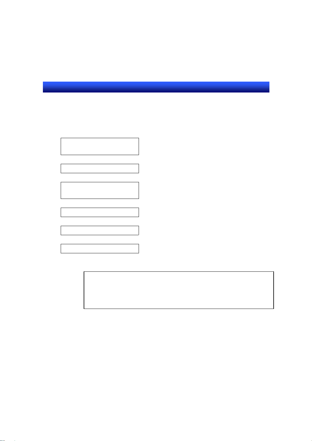
Present Value(1)
Screen1
Add a macro function to the object on screen1 which was created in Section4
STEP1.
Function Outline
1. Set value1
Add a macro function which sets the calculation result of set value1 to a set
value2.
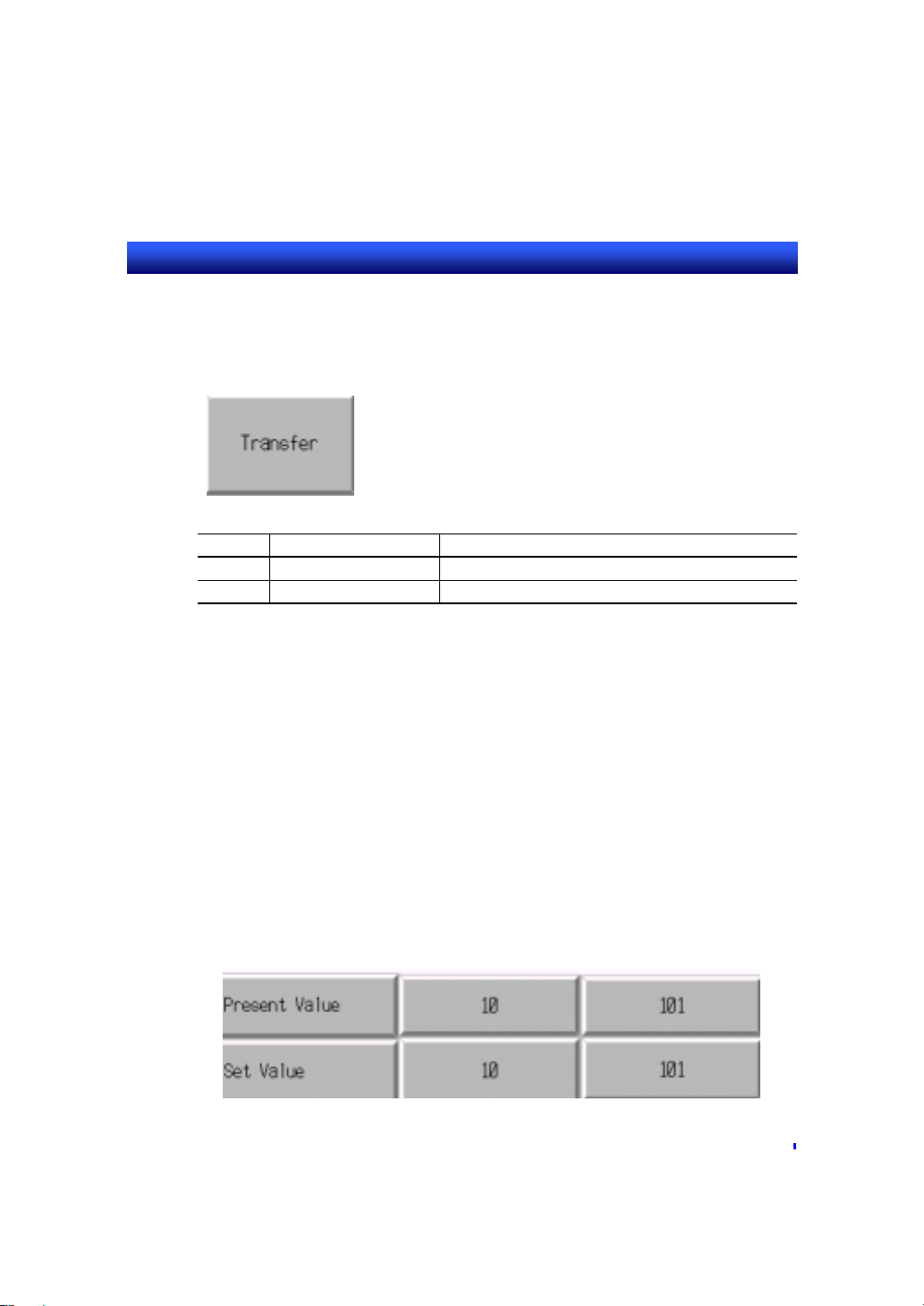
2. Transfer button
Add a function to transfer the set value1 and set value2 to PLC addresses.
Transmitted results will be displayed at present value1 and present value2.
Present Value(2)
Set Value(2)
Set Value(1)
Transfer Button
7 - 1
Page 72

Section7 STEP4 Creating Macro
NS series Tutorial Manual
7-2 Registering a Macro
The actual operations for registering and setting a macro function are
described.
Registering a macro for set value1
1. Open the property setting dialog of set value1.
2. Check ON “Display expansion tabs”.
3. Select [Macro] tab.
4. Choose the execution condition.
Check ON “When Changing Numeral”.
5. Edit a macro.
Click on [Edit macro] button.
6. Edit macro dialog is displayed.
7 - 2
Page 73

Section7 STEP4 Creating Macro
NS series Tutorial Manual
7. Input the description shown below in [program] field.
$W1=$W0*10+1;
‘The value of $W0 (set value1) is multiplyed by 10 and 1 is added. The result is set to
$W1 (set value2).
The description after “‘” is a comment. It is possible to omit this. In case you
include this, however, be sure to input this within 1 line. If the description is
interrupted by a return key, the description after it will not be regarded as a
comment (error occurs).
8. Click on [OK] button to close the property.
7 - 3
Page 74
Section7 STEP4 Creating Macro
NS series Tutorial Manual
Registering a macro for a transfer button
1. Create ON/OFF button and set the property as shown below.
Tab Item Contents
General Action Type Momentary
Label Label Transfer
2. Register a macro.
Choose “T ouch ON timing” for execution condition and input the description shown below in edit
macro dialog.
WRITECMEM([HOST1:DM00000],$W0,2);
‘The value $W0, $W1 is written to DM00000, DM00001 each.
The creation of macro function sample is finished. Save a screen and perform a
test.
R
e
f
e
r
e
n
c
e
R
e
f
e
r
R
e
f
e
In test mode, the behavior will be as follows.
If you input 10 to set value1, 101 (=10*10+1) is automatically set to set value2.
Then, when you click on the Transfer button, 10, 101 are input to present
value1,2 each (the value of set value1,2 is written to present value1,2).
e
n
c
e
r
e
n
c
e
7 - 4
Page 75

Section8 STEP5 Operation on the NS Hardware
NS series Tutorial Manual
Section8 STEP5 Operation on the NS
Hardware
This section describes the procedure to transmit the created data to NS
hardware to operate it.
Here, the data transfer procedure using RS-232C is described.
For details of the data transfer procedure using Ethernet, refer to section9.
8-1 Operation Procedure
・・・・・・・・・・・・・・・・・・・・・・・・・・・・・・・・・・・
8-2 Connecting NS Hardware and a Personal Computer
8-3 Transferring Data
8-4 Restarting NS Hardware and Connecting to PLC
8-5 Executing a Project
・・・・・・・・・・・・・・・・・・・・・・・・・・・・・・・・・・・・・・
・・・・・・・
・・・・・・・・・・・・・・・・・・・・・・・・・・・・・・・・・・・・
・・・
8 - 1
8 - 2
8 - 3
8 - 5
8 - 5
Page 76
Section8 STEP5 Operation on the NS Hardware
NS series Tutorial Manual
8-1 Operation Procedure
The procedures to transmit the created data to NS hardware and the operation
of NS hardware after transmission are described.
Connect NS hardware and
a personal computer
|
Transfer Data
|
Connect NS hardware and
Check the Dip switches
Restart NS hardware
Operate project data
a PLC
|
|
|
NOTE
Before restarting NS hardware, please be sure to check the setting of Dip
switches. Depending on the setting, data transfer may be
executed from a memory card. Set the Dip switches so that the
data transfer is not executed. For details, refer to set up manual
“3-5 Using a memory card”.
8 - 1
Page 77
Section8 STEP5 Operation on the NS Hardware
NS series Tutorial Manual
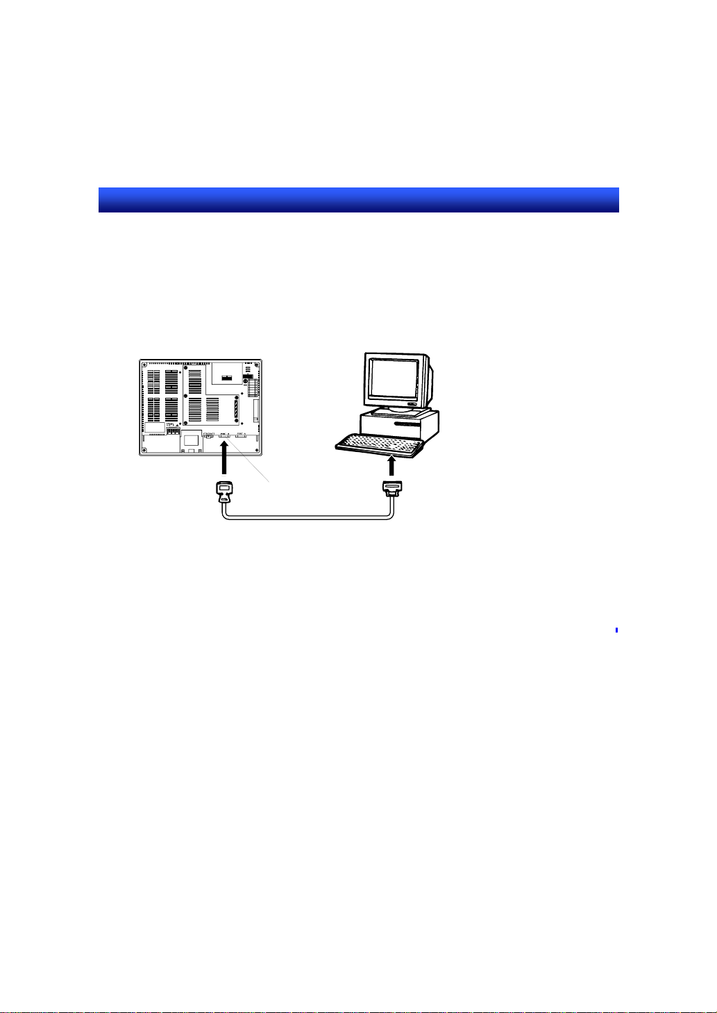
8-2 Connecting NS Hardware and a Personal Computer
To transfer the data, connect a personal computer (NS-Designer) and NS
hardware using RS-232C cable.
Connect a cable at serial port B on NS hardware side.
Serial port B
(RS-232C)
R
e
f
e
r
e
n
c
e
R
e
f
e
r
R
e
f
e
For details of the communication cable (RS-232C), refer to set up manual
“Section2 Preparation before connection” and “Appendix5 Creating a cable
connected to a personal computer”.
e
n
c
e
r
e
n
c
e
8 - 2
Page 78
Section8 STEP5 Operation on the NS Hardware
NS series Tutorial Manual
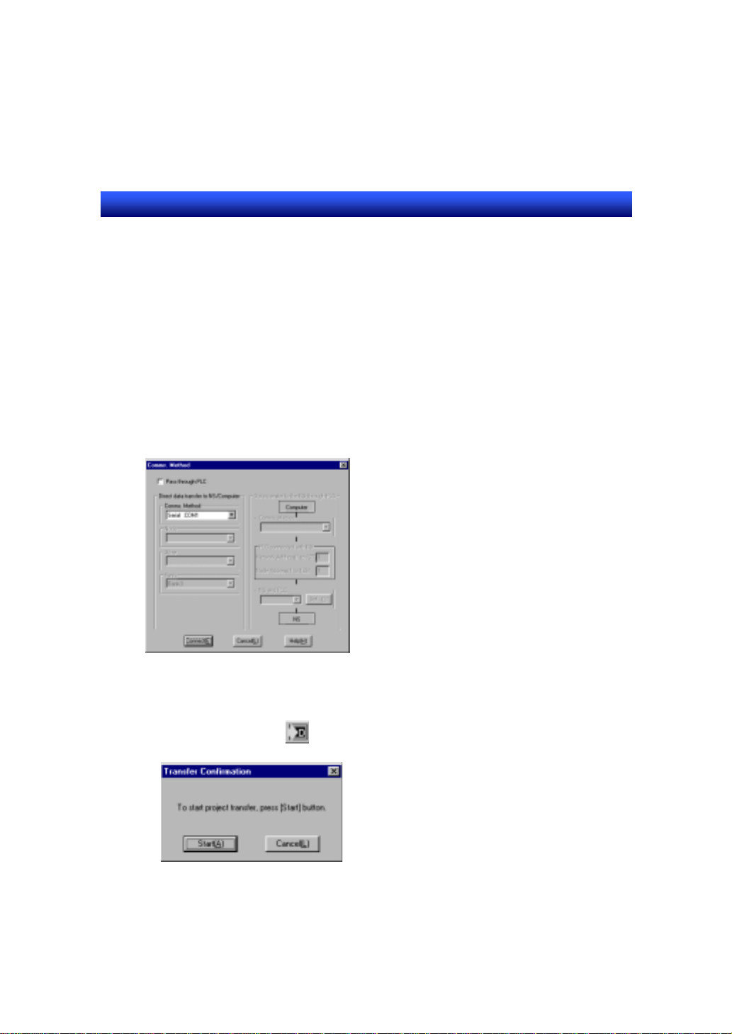
8-3 Transferring Data
Transfer the project data “Project” which you created with an NS-Designer to
NS hardware.
1. Select [Select project] under [Download Project].
2. Select the project to be transferred.
Select “Project” after clicking [Select Project] button.
3. Set communication method.
(1) Click on [Comms. Method] button.
(2) Set “Serial: COM1” as a communication method.
(3) Click on [Connect] button.
4. Select the data to be transferred.
Check ON “Select all”.
5. When you click on button, [Confirmation] dialog is displayed. Data
transfer starts after you click on [Start] button.
8 - 3
Page 79

Section8 STEP5 Operation on the NS Hardware
NS series Tutorial Manual
R
e
f
e
r
e
n
c
e
R
e
f
e
r
R
e
f
e
Data transfer program is an individual application. It can be also started without
starting up the NS-Designer.
To start up only the Transfer program, click on [Start] button of Windows and
select [Programs] – [Omron] – [[NS-Designer] - [Transfer Tool].
When data transfer is not possible, check the following points.
- Is the cable connected correctly?
- Is the power for NS hardware ON? Check if the starting message which is
displayed immediately after turning the power ON is shown?
e
n
c
e
r
e
n
c
e
8 - 4
Page 80
Section8 STEP5 Operation on the NS Hardware
NS series Tutorial Manual
8-4 Restarting NS Hardware and Connecting to PLC
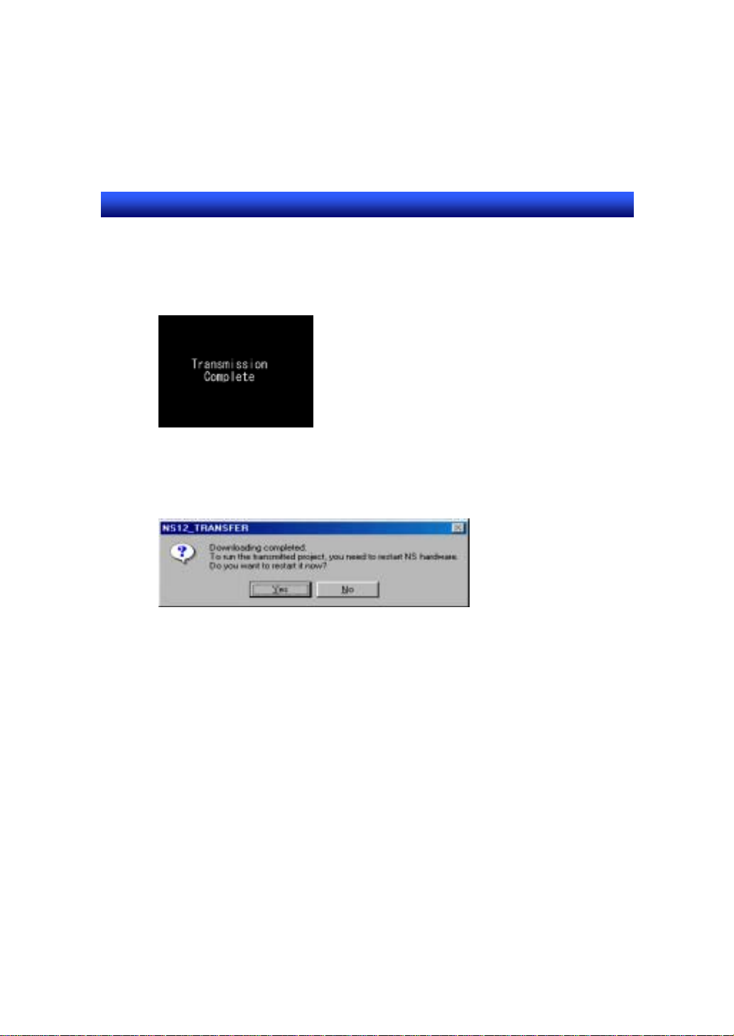
1. When the data transfer is completed, the screen shown below is displayed.
2. NS hardware sho uld be res et after transferring data. Click on [Yes] button in
the message dialog shown below which is displayed on a personal computer
after data transfer.
3. Connect PLC and NS hardware. Connect a cable to serial port A at the NS
hardware side.
8-5 Executing a Project
The project “Project” will be executed after turning ON the power for NS
hardware.
The created screen will be displayed in 10 seconds.
8 - 5
Page 81

Section9 Ethernet Connection
NS series Tutorial Manual
Section9 Ethernet Connection
This section describes the procedure to connect NS hardwa re and a PLC using
Ethernet.
9-1 System Configuration
9-2 Setting FinsGateway
9-3 Setting an Ethernet Unit
9-4 Setting a PLC
・・・・・・・・・・・・・・・・・・・・・・・・・・・・・・・・・・・・・・・・・・
9-5 Setting at NS-Designer
・・・・・・・・・・・・・・・・・・・・・・・・・・・・・・・・・・
・・・・・・・・・・・・・・・・・・・・・・・・・・・・・・・・・・・
・・・・・・・・・・・・・・・・・・・・・・・・・・・・・・・・
・・・・・・・・・・・・・・・・・・・・・・・・・・・・・・・
9-6 Conneting NS Hardware and a Personal Computer
9-7 Transferring data
・・・・・・・・・・・・・・・・・・・・・・・・・・・・・・・・・・・・・
・・・
9 - 1
9 - 2
9 - 6
9 - 9
9 - 16
9 - 20
9 - 21
Page 82

Section9 Ethernet Connection
NS12 チュートリアルマニュアル
NS series Tutorial Manual
9-1 System Configuration
System configuration is as shown below . One NS hardware is connected to two
PLCs using Ethernet.
Serial cable
Software : CX-Programmer
IP address : 10.3.65.4
Network No. : 1
Node No. : 4
Sub net mask : 255.255.255.0
-
NS-Designer
Peripheral port
Item Setting Page
Ethernet unit IP address
PLC I/O table
NS-Designer Network No.
FinsGateway Network No.
PLC1
Device Type : CS1H-CPU67
IP address : 10.3.65.1
Unit No. : 0
Node No. : 1
Conversion : Auto
Sub net mask : 255.255.255.0
NS hardware
10base -T
Twisted pair straight cable
Hub
Unit No.
Node No.
Routing table
Node No.
UPD port No.
IP address
Sub net mask
Conversion table
Host name
Local node No.
Conversion table
IP address : 10.3.65.3
Network No. : 1
Node No. : 3
Sub net mask : 255.255.255.0
PLC2
Device Type : CS1H-CPU67
IP address : 10.3.65.2
Unit No. : 1
Node No. : 2
Conversion : Auto
Sub net mask : 255.255.255.0
9-6
9-7
9-8
9-9
9-13
9-14
9-16
9-2
9 - 1
Page 83

Section9 Ethernet Connection
NS12 チュートリアルマニュアル
NS series Tutorial Manual
9-2 Setting FinsGateway
To connect NS hardware and a personal computer using Ethern et, you need to
make a setting of FinsGateway beforehand. For details of the operation of
FinsGateway, refer to the online help of FinsGateway. For details of the
Ethernet unit, refer to the manual.
1. Click on [Start] button of Windows and select [Programs] – [Fins Gateway] –
[Service Manager].
2. PLC icon is displayed at the lower right position on the screen. Right click the
icon and select [Setting].
3. Open the [Basic] tab and select [Services] from the left side of the window.
4. Select ”ETN_UNIT” from [Service Settings] and click on [Start]. (After you
click on [Start] button, the status changes to “Start” and the button name
changes to “Stop”.)
5. Select [Network] – [Network and Units] from the left side of the window.
6. Double click [Ethernet] under [Units] in [Network and Unit Settings] window
on the right. [ETN_UNIT Properties] dialog is displayed.
7. Click on [Network] tab and set [Network Number] and [Local Node Number]
as follows. Use default setting for [Communication unit Number].
9 - 2
Page 84

Section9 Ethernet Connection
NS12 チュートリアルマニュアル
NS series Tutorial Manual
Item Contents
Network Number 1
Local Node Number 4
R
e
f
e
r
e
n
c
e
R
e
f
e
r
R
e
f
e
For local node No., set the end number of IP address of a personal computer
you are using.
If IP address is 10.3.65.4, set 4.
8. Create a conversion table in [Node] tab. Select [IP address table ] at [FINS-IP
conversion] in [Communication Unit] tab. In [Nodes] tab, press [Add] button
to display [Ethernet Node Definition] dialog. Add “Node No.” and ”IP
address” of NS hardware and a personal computer. Click on [OK] button.
e
n
c
e
r
e
n
c
e
9 - 3
Page 85

Section9 Ethernet Connection
NS12 チュートリアルマニュアル
NS series Tutorial Manual
NS hardware
Item Contents
Node number 3
IP address 10.3.65.3
Personal computer
Item Contents
Node number 4
IP address 10.3.65.4
9. After you click on [OK] button, confirmation message to restart FinsGateway
is displayed. Click on [Yes].
10. After restarting FinsGateway, open [Nodes] tab again and confirm that the
“Model” is not “Unknown”. Press [OK] button.
9 - 4
Page 86

Section9 Ethernet Connection
NS12 チュートリアルマニュアル
NS series Tutorial Manual
R
e
f
e
r
e
n
c
e
R
e
f
e
r
R
e
f
e
With NS-Designer Ver. 2.X and earlier versions, data must be transferred via
♦
serial cable or Memory Card before transferring data via Ethernet. This is not
necessary with Ver. 3.X or later versions.
11. Select [Exit] from [File] menu.
e
n
c
e
r
e
n
c
e
9 - 5
Page 87

Section9 Ethernet Connection
NS12 チュートリアルマニュアル
NS series Tutorial Manual
9-3 Setting an Ethernet Unit
With an Ethernet unit, set IP address, unit No and node No.
For details of the Ethernet unit, refer to a manual.
Setting an IP address
1. Set an IP address using the rotary switches at the back of Ethernet unit. IP
address of PLC1 is 10.3.65.1. Convert this value to hexadecimal and set
each switch.
Item (SWNo.) Contents (hexadecimal) IP Address (decimal)
SW1 0
SW2 A
SW3 0
SW4 3
SW5 4
SW6 1
SW7 0
SW8 1
10
3
65
1
9 - 6
Page 88

Section9 Ethernet Connection
NS12 チュートリアルマニュアル
NS series Tutorial Manual
R
e
f
e
r
e
n
c
e
R
e
f
e
r
R
e
f
e
Rotary SW1 and SW2/SW3 and SW4/SW5 and SW6/SW7 and SW8 make a
pair.
SWNO. 1 2.3 4.5 6.7 8
Setting 0 A.0 3.4 1.0 1
IP address 1 0. 3 .6 5. 1
2. Set the IP address 10.3.65.2 of PLC2 in the same manner.
SW1 0
SW2 A
SW3 0
SW4 3
SW5 4
SW6 1
SW7 0
SW8 2
e
n
c
e
r
Item (SWNo.) Contents (hexadecimal) IP Address (decimal)
e
n
c
e
10
3
65
2
Setting unit No.
1. Set a unit number using the rotary switch at the front of Ethernet unit.
Unit No. of PLC1 is 0. Set “0” for “UNIT No.” rotary switch.
2. Set “1” for “UNIT No.” rotary switch of PLC2 in the same manner.
9 - 7
Page 89

Section9 Ethernet Connection
NS12 チュートリアルマニュアル
NS series Tutorial Manual
Setting a node number
1. Set a node number using the rotary switch at the front of Ethernet unit. Node
number at PLC1 side is 1. Set “1” for “NODE No.” rot ary switch “×16
set ”0” for “NODE No.” rotary switch ” ×16
R
e
f
e
r
e
n
e
c
R
e
f
e
r
R
e
f
e
When you select auto for conversion type at unit setting in Ethernet unit , set the
last digit (SW7,8) of IP address for node number.
2. Set “2” for “NODE No.” rotary switch “×160”, and set ”0” for “NODE No.”
rotary switch ” ×16
e
n
e
c
r
e
n
e
c
1
” for PLC2 in the same manner.
1
”.
0
”, and
9 - 8
Page 90
Section9 Ethernet Connection
NS12 チュートリアルマニュアル
NS series Tutorial Manual
9-4 Setting a PLC
Set an I/O table and routing table with PLC.
Use CX-Programmer to set these items. For details of the operation method of
CX-Programmer, refer to “CX-Programmer Operation Manual (SBCA-305□)”.
Creating an I/O table
1. Connect PLC1 and a personal computer via peripheral port.
If you are using a programming console, remove it.
2. Start up CX-Programmer.
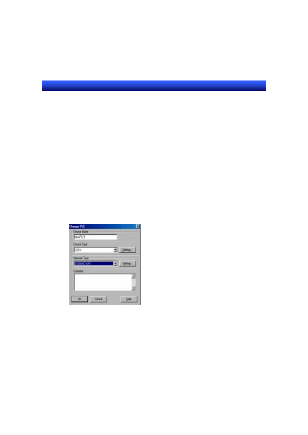
3. Select [New] from [File] menu.
In the displayed dialog, set “CS1H” for “Device Type” and set “SYSMAC W AY”
for “Network type”.
Click on [Setting] button at the right side of [Device Type] and set [CPU67] for
[CPU Type]. Use the default settings for others.
9 - 9
Page 91

Section9 Ethernet Connection
NS12 チュートリアルマニュアル
NS series Tutorial Manual
4. Click on [OK] button.
5. Select [Work Online] from [PLC] menu.
6. Select [PLC] – [Operating mode] – [Program].
7. Select [PLC] –[EDIT] – [I/O table] and click it.
8. Select [Options] – [Create] in the displayed [PLC I/O table] dialog.
9 - 10
Page 92
Section9 Ethernet Connection
NS12 チュートリアルマニュアル
NS series Tutorial Manual
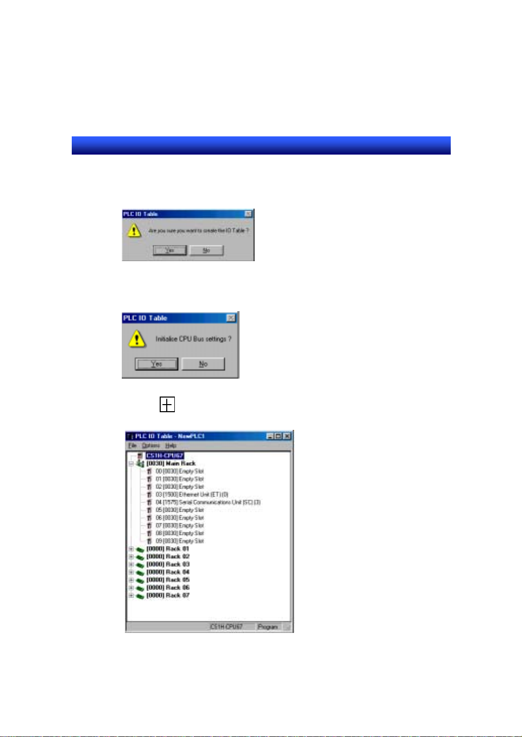
9. The message to confirm the creation of I/O table is displayed. Click on [Yes]
button.
The message to initialize the CPU bus setting is displayed. Click on [Yes]
button.
10. Click on button at the left side of [0030] Main Rack in [PC I/O table]
dialog. [Ethernet unit] is displayed.
9 - 11
Page 93
Section9 Ethernet Connection
NS12 チュートリアルマニュアル
NS series Tutorial Manual
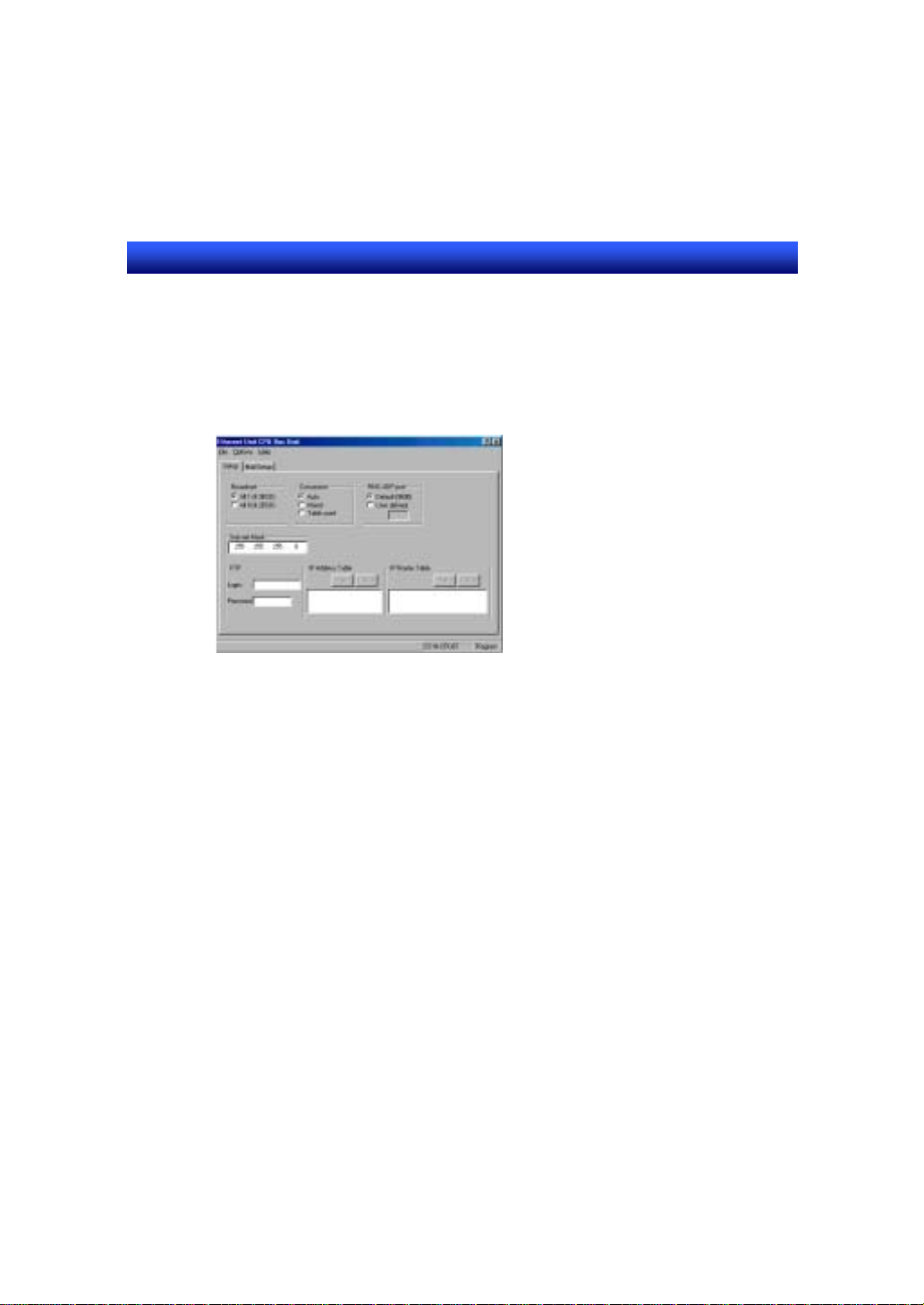
11. Select [Ethernet Unit] and specify [Unit Setup] from the pop-up menu
displayed by right clicking of a mouse.
12. Set “Auto” for “Conversion” and set “255.255.255.0” for “Sub-net mask” in
[Ethernet CPU Bus Unit] dialog. Use default settings for others.
13. Select [Transfer to PLC] from [Options] menu.
14. Select [Verify] from [Options] menu.
15.Click on [OK] button close [Ethernet CPU Bus Unit] dialog.
16. Select [Transfer to PLC] from [Options] menu in [PC I/O table] dialog.
17. Press [YES] button to close [PC I/O table] dialog.
18. Select [Work Online] from [PLC] menu to disconnect.
19. Perform the setting for PLC2 in the same manner.
9 - 12
Page 94
Section9 Ethernet Connection
NS12 チュートリアルマニュアル
NS series Tutorial Manual
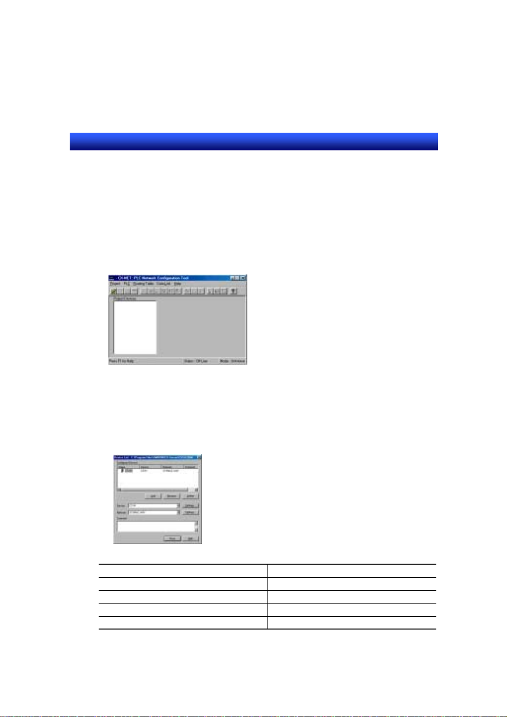
Creating a routing table
1. Select [Network Configuration Tool] from [Tools] menu using
CX-Programmer.
The description here is based on Network Configuration Tool Ver1.5. For
details of the setting method of prior version, refer to the manual of Network
Configuration Tool.
2. Select [New] from [Project] menu. Input CS1H_1.CDM as a file name.
3. Select [Edit] from [Project] menu.
4. Set [Device list] dialog as shown below.
Item Contents
[Add] button CS1H
Device CS1H
Set (Device) – CPU Type CPU67
Network SYSMAC WAY
9 - 13
Page 95
Section9 Ethernet Connection
NS12 チュートリアルマニュアル
NS series Tutorial Manual
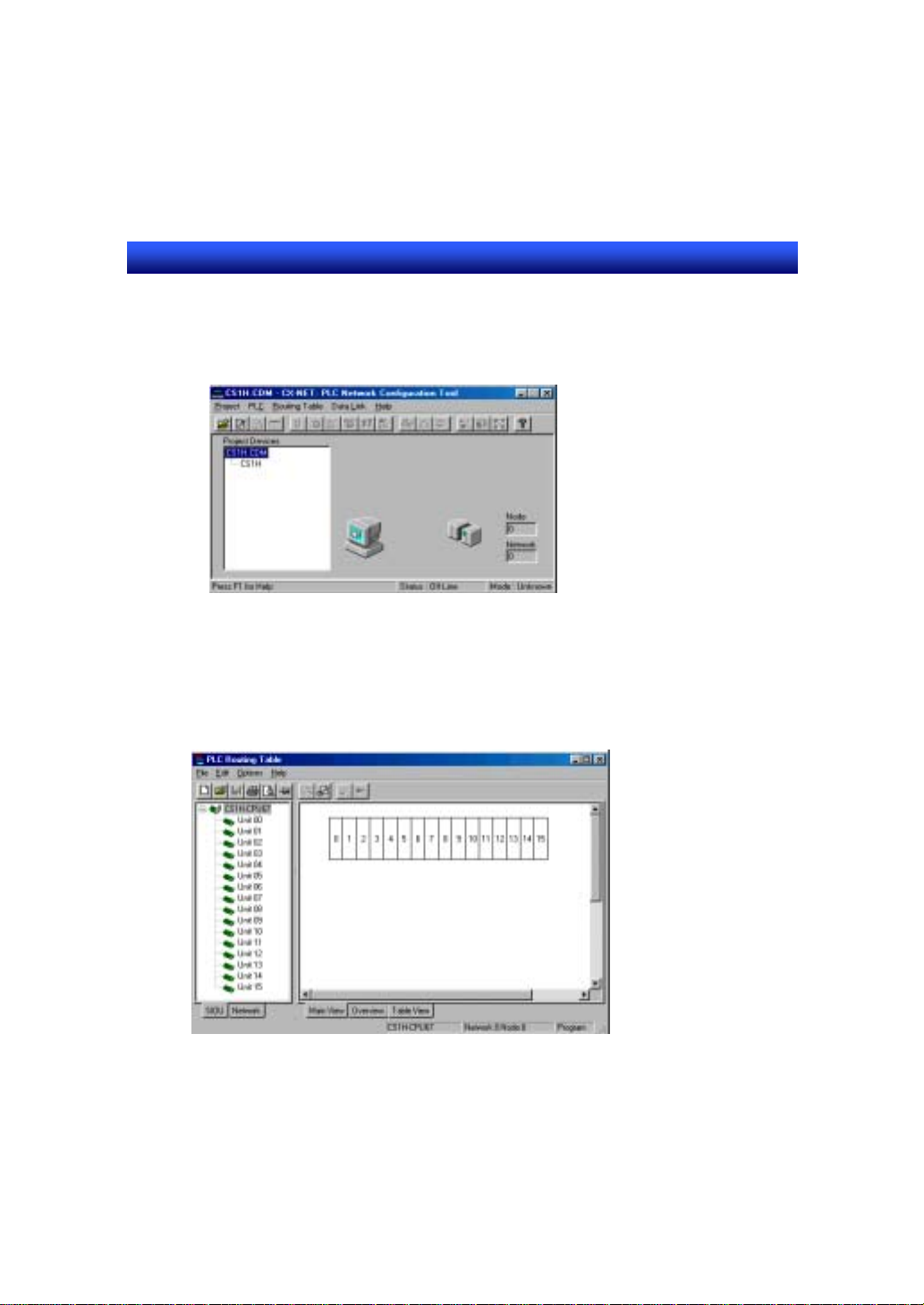
5. File name and added PLC are displayed in a main window of Network
Configuration Tool. Select PLC name and confirm that the figures of
personal computer and PLC at the right side of main window are connected
with a red line.
6. Focus on [CS1H] you edited below [CS1H.CDM] then select [Open] from
[PLC] menu. Confirm that the line displayed in 5 is changed to green.
7. Select [Set] from [Routing table] menu. PC routing table dialog opens.
8. Select [Add local network] from [Edit] menu.
9 - 14
Page 96

Section9 Ethernet Connection
NS12 チュートリアルマニュアル
NS series Tutorial Manual
9. Set [Enter SIOU Details] dialog as shown below.
Item Contents
CPU SIOU 0
Local network No. 1
Local network type ENT
10. Click on [OK] button to close [Enter SIOU Details] dialog.
11. Select [Transfer to PLC] from [Options] menu and transfer the setting
contents to a PLC.
12. Save the setting contents by selecting [File] – [Save local routing table file] if
needed.
13. Close [PLC routing table] dialog.
14. Exit Network Configuration Tool.
9 - 15
Page 97

Section9 Ethernet Connection
NS12 チュートリアルマニュアル
NS series Tutorial Manual
9-5 Setting at NS-Designer
Perform system settings and host registration with the NS-Designer. By
downloading the set data to NS hardware, the settings are overwritten to NS
hardware.
1. Start up an NS-Designer and open a project.
2. Select [System setting] from [Settings] menu.
3. Choose [Enable] for [Ethernet] in [Comm-All] tab.
4. Set [Ethernet] tab as shown below.
Item Contents
Network No. 1
Node No. 3
UDP Port No. 9600
IP Address 10.3.65.3
Sub-net Mask 255.255.255.0
5. Click on [Add] button to open [IP Address setting] dialog.
9 - 16
Page 98

Section9 Ethernet Connection
NS12 チュートリアルマニュアル
NS series Tutorial Manual
Set PLC1 as shown below.
Item Contents
Node No. 1
IP Address 10.3.65.1
6. Click on [OK] button to close the dialog.
7. Repeat the operations 5 and 6 three times to set PLC2, NS hardware and a
personal computer. Set as follows.
9 - 17
Page 99

Section9 Ethernet Connection
NS12 チュートリアルマニュアル
NS series Tutorial Manual
9 - 18
Page 100

Section9 Ethernet Connection
NS12 チュートリアルマニュアル
NS series Tutorial Manual
PLC2
Item Contents
Node No. 2
IP Address 10.3.65.2
NS hardware
Item Contents
Node No. 3
IP Address 10.3.65.3
Personal computer
Item Contents
Node No. 4
IP Address 10.3.65.4
8. Click on [OK] button to close [System Setting] dialog.
9. Select [Register host] from [Settings] menu.
10. Click [Add] button. [Edit host] dialog is displayed.
Set PLC1 as shown below.
Item Contents
Host Name CS1H_1
Network No. 1
Node Address 1
PLC Type SYSMAC-CS1
11. Click on [OK] button to close [Register host] dialog.
9 - 19
 Loading...