

Page 1

OPERATION MANUAL
RGB and Video Input Unit
NS-Series
Programmable Terminals
Cat.No. V086-E1-02
Page 2

Notice
OMRON products are manufactured for use according to proper procedures by a
qualified operator and only for the purposes described in this manual.
The following conventions are used to indicate and classify precautions in this manual.
Always heed the information provided with them. Failure to heed precautions can result
in injury to people or damage to property.
! DANGER Indicates an imminently hazardous situation which, if not avoided, will
result in death or serious injury.
! WARNING
! Caution
OMRON Product References
All OMRON products are capitalized in this manual. The word "Unit" is also capitalized
when it refers to an OMRON product, regardless of whether or not it appears in the
proper name of the product.
The abbreviation "Ch," which appears in some displays and on some OMRON products,
often means "word" and is abbreviated "Wd" in documentation in this sense.
The abbreviation "PLC" means Programmable Controller.
The abbreviation “host” means a controller , such as an IBM PC/A T or compatible
computer, that controls a PT (Programmable Terminal).
Indicates a potentially hazardous situation which, if not avoided, could
result in death or serious injury.
Indicates a potentially hazardous situation which, if not avoided, may
result in minor or moderate injury, or property damage.
Visual Aids
The following headings appear in the left column of the manual to help you locate
different types of information.
Note
Reference
1, 2, 3...
Indicates information of particular interest for efficient and
convenient operation of the product.
Indicates supplementary information on related topics that may be
of interest to the user.
Indicates lists of one sort or another, such as procedures,
checklists, etc.
Ó OMRON, 2004
All rights reserved. No part of this publication may be reproduced, stored in a retrieval system, or transmitted, in any form,
or by any means, mechanical, electron ic, photocopying, rec o rding, or otherwise, wit hout the prior written permission of
OMRON.
No patent l iability is ass um e d with respect to the use of t he information co ntained here in. Moreover, because OMRON is
constantly stri ving to improve its high-quality products, the information contained in this manual is subject to change
without notice. Every precaution has been taken in the preparation of this manual. Nevertheless, OMRON assumes no
responsibili ty for errors or omissions. Neither is any liability assumed for damages resulting from the use of the
information cont ained in this publication.
1
Page 3

Contents
Notice ........................................................................................................................1
About this Manual ......................................................................................................... 4
Related Manuals ............................................................................................................ 5
Terminology .................................................................................................................. 6
Introduction....................................................................................................................7
Precautions for Safe Use................................................................................................ 9
Precautions for Correct Use......................................................................................... 10
Section 1 Overview
1-1 RGB and Video Input Unit Features........................................................................... 1-2
1-2 System Configuration ................................................................................................. 1-3
Section 2 Installing the RGB and Video Input Unit
2-1 RGB and Video Input Unit Components.................................................................... 2-2
2-2 Nomenclature and Functions ......................................................................................2-3
2-3 Installing the RGB and Video Input Unit ...................................................................2-4
2-4 Connecting Video Input Connectors...........................................................................2-9
2-5 Connecting the RGB Input Connector ......................................................................2-11
2-6 Connecting the Console Port Connector ................................................................... 2-12
Section 3 RGB and Video Input Unit Functions
3-1 Display ..................................................................................................................... 3-2
3-1-1 Video Display.................................................................................................. 3-2
3-1-2 RGB Display ................................................................................................... 3-9
3-1-3 Changing the Video Board Field Setting....................................................... 3-12
3-2 Video Capture ........................................................................................................... 3-15
3-3 Console Connection .................................................................................................. 3-17
3-4 Settings and Adjustments.......................................................................................... 3-18
3-4-1 System Settings ............................................................................................. 3-18
3-4-2 Video Configuration...................................................................................... 3-19
3-4-3 Contrast Adjustor Settings.............................................................................3-22
3-4-4 RGB Configuration .......................................................................................3-23
2
3-4-5 Video Display Control................................................................................... 3-26
Page 4

Appendices
Appendix 1 Specifications ..............................................................................................A-2
Appendix 2 Pin Arrangement .........................................................................................A-3
Appendix 3 Dimensions .................................................................................................A-4
Appendix 4 Comparison to NS-CA001 Video Input Unit..............................................A-5
3
Page 5

About this Manual
Section 1 Overview
Provides an outline of the RGB and Video Input Unit, including its features and system
configuration.
Section 2 Installing the RGB and Video Input Unit
Describes the nomenclature and functions of each part, the procedure for installing the RGB and
Video Input Unit on a PT, and the procedure for connecting external devices to the Unit.
Section 3 RGB and Video Input Unit Functions
Describes the functions available when using an RGB and Video Input Unit along with the setting
and adjustment procedures required for its operation.
Appendices
Provides hardware specifications, dimensions, and NS-CA001 comparison information.
WARNING
Failure to read and understand the information provided in this
manual may result in personal injury or death, damage to the product,
or product failure. Please read each section in its entirety and be sure
you understand the infor mation provided in the s ection and related
sections before attempting any of the procedures or operations
given.
4
Page 6

Related Manuals
The following manuals are used for NS-series PTs. (The boxes at the end of the catalog
numbers indicate the revision code.)
l NS Series -V1 Setup Manual.....................................................V083-E1-¨
Provides information on NS-V1 Series models (i.e., the NS12-V1, NS10-V1,
NS8-V1, and NS5-V1).
Describes how to conn ect the PT to the host and perip heral devic es, m ethods to
set up communications and operation, and procedures for maintenance.
Refer to th e NS Series Programming Manual (SBSA-512¨) for information on PT
functions and specific operating procedures.
l NS Series Setup Manual............................................................V072-E1-¨
Provides information on NS Series models (i.e., the NS12, NS10, and NS7).
l NS Series Programming Manual..............................................V073-E1-¨
Describes the sc reen configur ations, objec t functions, and host c ommunic ations
for the PT.
l NS-Designer Operation Manual................................................V074-E1-¨
Describes operating pr oc ed ures f or the NS-D esig ner, which is used to c reate t he
screens displayed on the PT and transfer them to the PT. It includes screen
creation and transfer procedures.
5
Page 7
Terminology
The following terminology is used in this manual.
PT
NS Series
PLC
CS/CJ Series
In this manual, indicates a Pro grammable Terminal in OMRON’s
NS Series of Programmable Terminals.
Indicates products in OMRON’s NS¨¨ Series of
Programmable Terminals.
Unless otherwise specified, the information in this manual
applies to the NS¨¨ Series.
Indicates Programmable Con trollers in the OMRON’ s SY SMAC
CS/CJ, C, or CVM1/CV Series of Programmable Controllers.
Indicates Programmable Controllers in OMRON’s SYSMAC
CS/CJ Series of Programmable Controllers: CS1G, CS1H,
CS1G-H, CS1H-H, CJ1G, and CJ1M.
6
Page 8

Introduction
Thank you for purchasing an RGB and Video Input Unit for the NS-series PT.
The RGB and Video Input Unit is an Expansion Unit that is installed on an NS-series
Programmable Terminal (PT) to display RGB signals from analog signal output devices,
such as personal computers, or pictures from devices such as video cameras and Vision
Sensors.
Refer to the NS Series Setup Manual, the NS Series Programming Manual, and the
NS-Designer Operation Manual for details on the functions and performance of the PT.
l Intended Audience
This manual is intended for the following personnel, who must also have knowledge of
electrical systems (an electrical engineer or the equivalent).
Personnel in charge of introducing FA systems into production facilities
· Personnel in charge of designing FA systems
· Personnel in charge of installing and connecting FA systems
· Personnel in charge of managing FA systems and facilities
l Notice
This manual provides information for connecting and setting up an RGB and Video Input
Unit for the NS-series PT . Be sure to read this manual before attempting to use the Unit
and keep this manual close at hand for reference during installation and operation.
l General Precautions
· The user must operate the product according to the performance specifications
described in the operation m anuals .
· Do not use the PT touch switch input functions for applications where danger to
human life or serious property damage is possible, or for emergency switch
applications.
· Before using the product under conditions which are not described in the manual or
applying the product to nuclear control systems, railroad systems, aviation systems,
vehicles, combustion systems, medical equipment, amusement machines, safety
equipment, and other systems, machines and equipment that may have a serious
influence on lives and property if used improperly, consult your OMRON
representative.
· Make sure that the ratings and performance characteristics of the product are
sufficient for the systems, machines, and equipment, and be sure to provide the
systems, machines, and equipment with double safety mechanisms.
· This manual provides information for connecting and setting up an NS-series PT.
Be sure to read this manual before attempting to use the PT and keep this manual
close at hand for reference during installation and operation.
7
Page 9
l Safety Precautions
Do not attempt to take the Unit apart an d do not
touch any internal parts while the po wer is being
supplied. Doing either of these may result in
electrical shock.
8
Page 10

Precautions for Safe Use
· On unpacking the Unit and peripheral devices, check the external appearance and
confirm that there is no damage. Also, shake the Unit gently and be sure there are
no abnormal sounds.
· Be sure that metal scraps do not fall into the Unit when preparing the panel for
installation.
· The power supply must have re inforced insu lation to con form to the EC Low Voltage
Directive.
· Be sure to ground the Unit properly to prevent malfunction due to noise.
· Do not touch the surface of the circuit board or the components mounted to it with
our bare hands. Discharge static electricity from your body before handling the
board.
· Before inserting or removing connectors, make sure that the Unit and the PT are
turned OFF.
· After connecting the cables, always secure the cable connectors with screws.
· The cable’s tensile load is 30 N max. Do not subject it to loads greater that this.
· Before turning power ON and OFF or pressing the reset switch, check the system to
confirm that it is safe to do so.
· The entire system may shut down depending on how the power is turned ON and
OFF. Follow the proper procedures for turning power ON and OFF.
· Carefully check the screen data, macros, and host program to make sure they are
operating properly before actually using them.
· Do not perform the following while the Memory Card is being accessed.
· Turning the power OFF on the PT
· Pressing the reset switch on the PT
· Removing the Memory Card
(Always follow the proper procedure for removing the Memory Card.)
· To ensure that the system operates safely, add a procedure to the program at the
host that periodically reads operation signals from the PT to see if the PT is
operating properly.
· Do not use more than 30 N of force to press touch switches.
· Before pressing touch switches, check the system to confirm that it is safe to do so.
· Do not press a touch switch when the display is not backlit or is blank.
· Touch switch inputs may not be entered if the switches are pressed too quickly in
rapid succession. Confirm each input before moving on to the next one.
· Always make sure that screen data is backed up on the NS-Designer before you
initialize screen data.
· Never use chemical wipes or volatile solvents, such as benzene or thinner, to clean
the Unit.
· Do not disassemble, repair, or modify the Unit.
· The disposal of the Unit and discarded batteries may be regulated by national or
local authorities. Dispose of them in accordance with the laws and regulations of the
relevant country and local authority.
9
Page 11

Precautions for Correct Use
· Do not install the Unit at sites subject to the following conditions. Otherwise the
product may malfunction.
Severe temperature variations
Temperature or humidity outside the ranges stated in the specifications
High humidity and condensation
Splashing of chemical agents
Severe oil splashing
Corrosive or flammable gases
Strong vibration or shock
Direct exposure to wind and rain (outdoor sites)
Strong ultra-violet irradiation
· Take adequate measures to ensure shielding if the Unit is used at a site subject to
any of the following conditions. Otherwise, the product may malfunction.
Static electricity or noise from other equipment
Strong electromagnetic fields
Nearby power cables
Potential exposure to radioac tiv ity
10
Page 12

Section 1 Overview
This section provides an outline of the RGB and Video Input Unit, including its functions,
features, and connection types.
RGB and Video Input Unit Features ··················································· 1-2
1-1
1-2 System Configuration·········································································· 1-3
Page 13

1-1 RGB and Video Input Unit Features
1-1 RGB and Video Input Unit Features
Install the RGB and Video Input Unit (NS-CA002) on the PT Expansion Interface to
display external video images or analog RGB pictures on the PT. The Unit is an option
for NS-series PTs.
● Features
• Two video input ports (composite NTSC/PAL signal)
• One analog RGB input port
Display resolution 800 x 600 (mounted to an NS12 PT)
640 x 480 (mounted to an NS10 or NS8 PT)
Horizontal frequency 37.5 kHz (mounted to an NS12 PT)
31.5 kHz (mounted to an NS10 or NS8 PT)
Vertical frequency 60 Hz
• One port for console output to a Vision Sensor Controller (same function key
operations as the F160-KP)
• Selectable video display size (and positionable displays)
• Overlapping on video displays (Functional objects and pop-up screens can
overlap video displays.)
* The above features apply only to PTs on which the RGB and Video Input Unit (NS-CA002) can be
installed. Refer to 1-2 System Configuration for details.
1- 2
Page 14
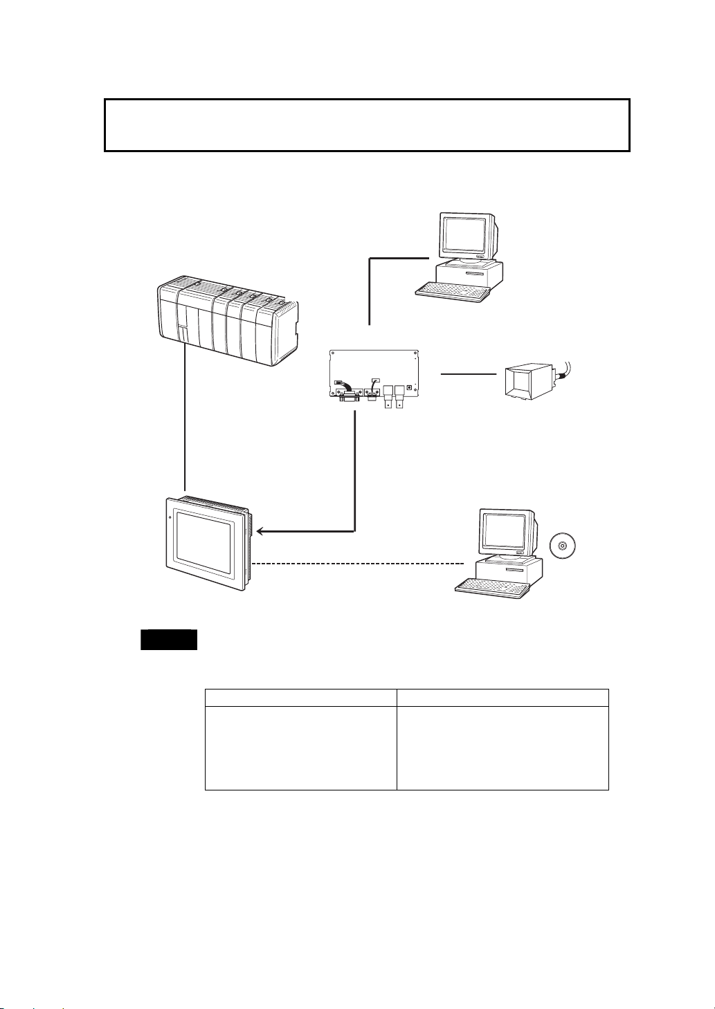
1-2 System Configuration
1-2 System Configuration
A system configuration using the RGB and Video Input Unit is shown below.
RGB cable
Host
Personal computer
Video camera or
Vision Sensor
NS-Designer
RS-232C cable
(15 m max.)
RS-422A cable
(500 m max.)
RS-232C/422A Adapter
Ethernet cable
RUN
RGB and Video Input Unit
NTSC/PAL
cable
Personal computer running
Windows 95, 98, NT, Me, 2000, or
XP
φ
NS-series PT
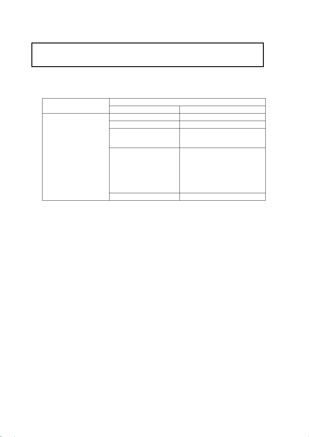
Note
The RGB and Video Input Unit (NS-CA002) operates only when installed on
the models in the Applicable column of the following table. Do not install it on
any other PT.
Applicable Not applicable
NS12-TS0@(B) -V1 NS12-TS0@ (B)
NS10-TV0@ (B) -V1 NS10-TV0@ (B)
NS8-TV@@ (B) -V1 NS7-SV0@ (B)
NS5-SQ0@ (B) -V1
1- 3
Page 15

Section 2 Installing the RGB and Video
Input Unit
This section describes the procedure for installing the RGB and Video Input Unit on an
NS-series PT and the procedure for connecting cables to the Unit.
2-1 RGB and Video Input Unit Components············································· 2-2
2-2 Nomenclature and Functions······························································· 2-3
2-3 Installing the RGB and Video Input Unit ············································ 2-4
2-4 Connecting Video Input Connectors···················································· 2-9
2-5 Connecting the RGB Input Connector ·············································· 2-11
2-6 Connecting the Console Port Connector ··········································· 2-12
Page 16
2-1 RGB and Video Input Unit Components
2-1 RGB and Video Input Unit Components
The following table shows the RGB and Video Input Unit model and product
configuration.
Model
RGB and video board (1) Allows video input and RGB input.
Cover (1) Protects the RGB and video board.
Cable (1) Connects the PT’s functional ground
RGB and Video Input Unit
NS-CA002
Operation manual Manual for the NS-CA002.
Screws (M3) (9) These screws are used for the
Name Contents
Components
terminal and the cover to prevent
noise.
following:
• Securing the RGB and video
board to the back of the PT.
• Securing the cover to the back of
the PT.
• Attaching the cable to the cover.
2- 2
Page 17
2-2 Nomenclature and Functions
2-2 Nomenclature and Functions
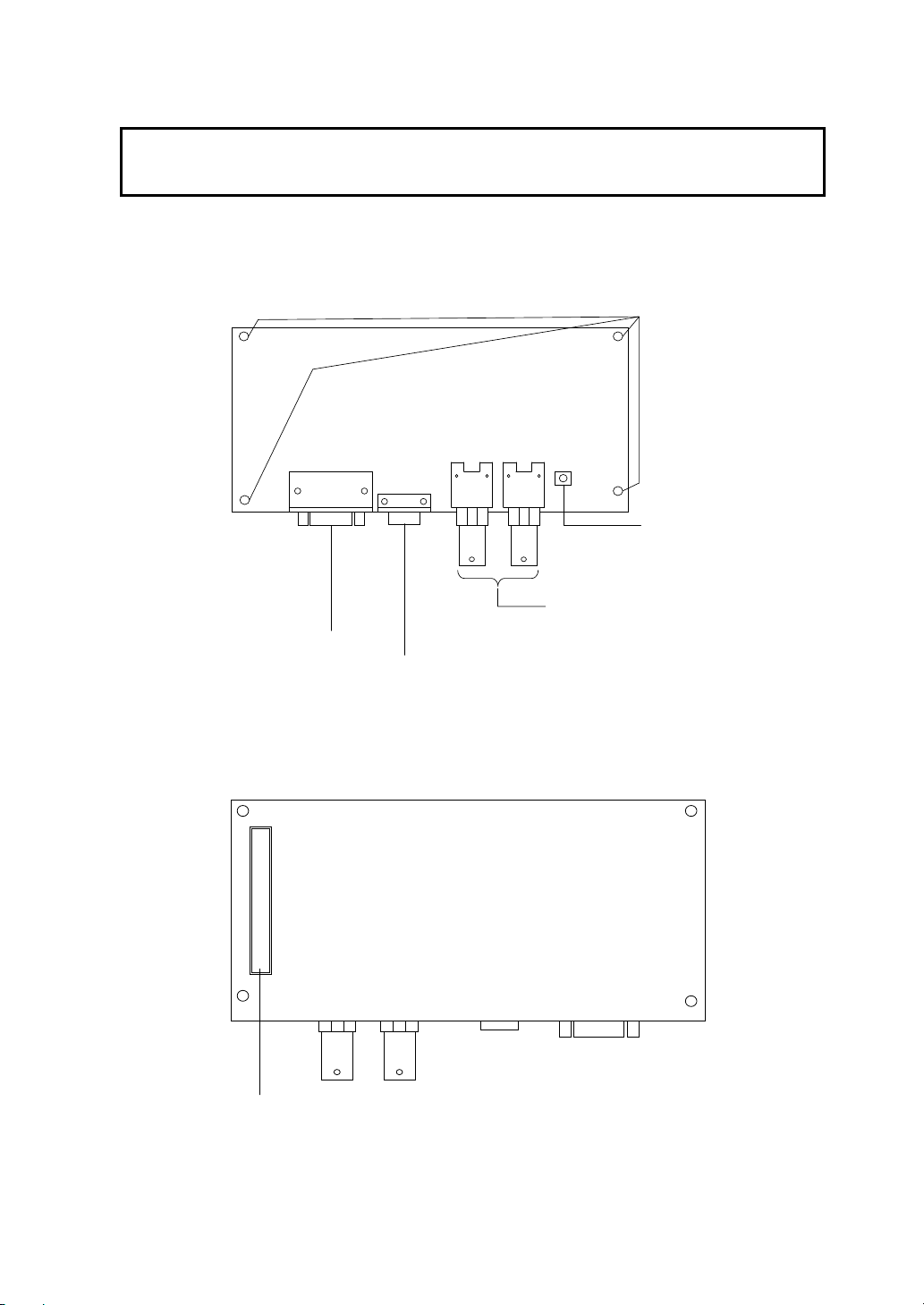
This section describes the names and functions of RGB and Video Input Unit parts.
z RGB and Video Board: Front View
Positions of screws for attaching
the board to the PT
Contrast Adjustor
Used to adjust the contrast of the
video input. Both channels are
adjusted together and cannot be
adjusted individually.
Analog RGB Input Connector
D-sub 15-pin connector
(Mini) used to connect a
device, such as a computer,
that outputs analog RGB
signals and allows displaying
pictures on the PT.
Console Port Connector
Connects to the console
connector of an OMRON Vision
Sensor and allows Vision
Sensor settings and other
operations to be performed from
the PT.
z RGB and Video Board: Rear View
Expansion Interface Connector
Connects to the PT’s expansion interface
connector when mounting the RGB and
video board.
Two Video Input Connectors
BNC-type connectors for inputting
NTSC/PAL signals.
2- 3
Page 18
2-3 Installing the RGB and Video Input Unit
p
2-3 Installing the RGB and Video Input Unit
This section describes the procedure for installing the RGB and Video Input Unit on
the PT.
Note
When complying with the EC Directive for the NS hardware with an RGB and Video
Input Unit mounted, make sure that the NS hardware is mounted on the control panel
and each cable is connected with a ferrite core.
Recommended Control Panel
Model Manufacturer
EC-SCF16-45 Nitto Electric Works, Ltd.
Recommended Ferrite Cores
Model Manufacturer Cable
ZCAT1518-0730 TDK Video Cable
ZCAT1518-0730 TDK Console Cable
ZCAT2035-0930 TDK RGB Monitor Cable
ZCAT1325-0530 TDK FG Cable
ZCAT-3035-1330 TDK AC Power Cable
ZCAT-2436-1330 TDK AC Power Cable
• Do not touch the surface of the circuit board or the components mounted to it with
your bare hands.
• After installing the Unit on the PT, always secure it with the screws provided. The
applicable mounting torque is 0.6 N·m.
• Before installing or removing the Unit, make sure that the Unit and the PT are turned
OFF. Make sure that installing or removing is carried out correctly as described in
Installing or Removing.
• When the Unit is installed, the depth of the PT increases by 24 mm. Make sure that
there is enough space in the control panel before installing the Unit.
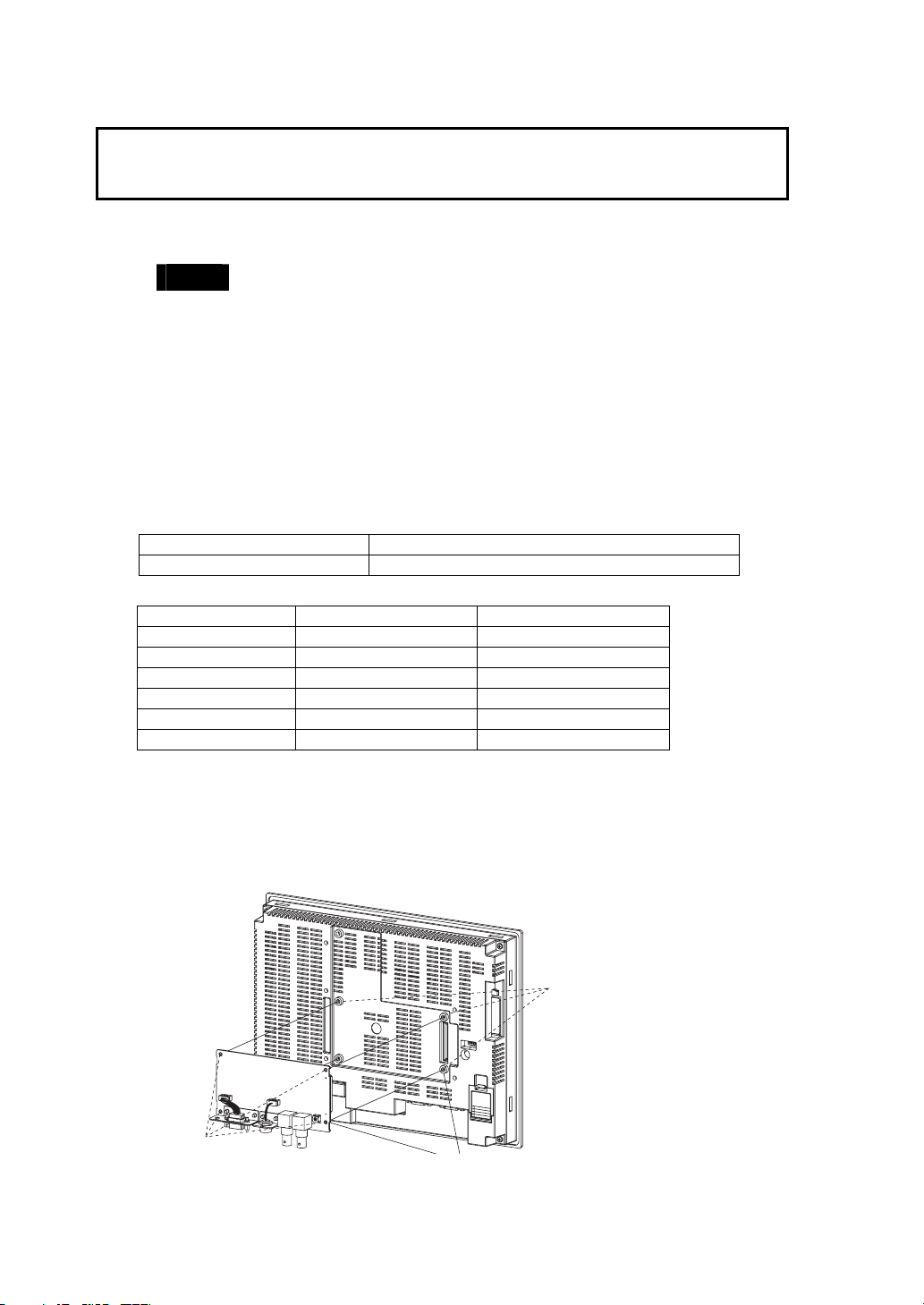
z Installing the RGB and Video Input Unit
(1) Install the RGB and video board so that its expansion interface connector is
inserted into the expansion interface connector on the back of the PT and the
respective screw holes are aligned. Hold the RGB and video board by the
corners, keeping it parallel to the back of the PT.
Screw holes for
attaching
ansion boards.
ex
Position of screws
for attaching the
board to the PT.
Align the positions of the
2- 4
Page 19
2-3 Installing the RGB and Video Input Unit
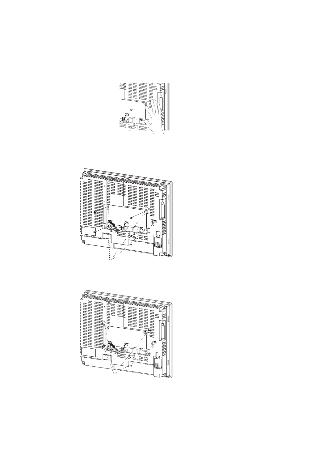
(2) Push firmly on the connector end of the board and make sure that it is inserted
sufficiently.
(3) Secure the four corners of the RGB and video board with screws.
Secure these four places with screws.
(4) Insert screws in the screw holes for attaching the cover and tighten them slightly.
Insert the screws first.
2- 5
Page 20

2-3 Installing the RGB and Video Input Unit
(5) Align the cover screw holes with the screws and mount the cover.
(6) Slide the cover downward and tighten the screws.
Mount the cover.
Slide the cover.
8
+
&
'
8
+
&
'
1
%
1
0
6
4
#
5
6
1
%
1
0
6
4
#
5
6
Tighten the screws.
2- 6
Page 21

2-3 Installing the RGB and Video Input Unit
z Connecting the Cable
Connect the functional ground terminal of the PT and the cover with the cable to
prevent malfunction due to noise.
㧿㨃
㨂㧵㧰㧱㧻
RESET
ޓ
㧼㧻㧾㨀
㧯㧻㧺㨀㧾㧭㧿㨀
㨂㧵㧰㧱㧻ޓ㧵㧛㧲
㧝㨏㨔㧞㨏㨔
PORT B PORT A
㨂㧵㧿㧵㧻㧺ޓ㧿㧱㧺㧿㧻㧾
ޓ
㧵㧛㧲
㧾㧳㧮
㧯㧻㧺㧿㧻㧸㧱
㧞㧠㨂
㧰㧯
㧴㧻㧿㨀 㧿㧸㧭㨂㧱
ETHERNET
Connect the functional ground terminal
and the cover with the cable.
z Removing the RGB and Video Input Unit
(1) Remove the cover from the back of the PT. Loosen the cover mounting screws
and slide the cover upward.
Slide the cover.
8
+
&
'1
%
1
06
4
#
56
Loosen the screws.
Remove the cover.
8
+
&
'
1
%
1
0
6
4
#
5
6
2- 7
Page 22

2-3 Installing the RGB and Video Input Unit
(2) Remove the cover and remove the screws securing the four corners of the RGB
and video board.
Remove the screws securing the four corners.
(3) Remove the RGB and video board from the expansion interface connector on
the back of the PT in the order shown in the following diagram.
(1) Hold the RGB and video board by the corners and remove it starting from the top.
(2) Pull the entire RGB and video board away from the PT.
2- 8
Page 23

2-4 Connecting Video Input Connectors
g
2-4 Connecting Video Input Connectors
This section describes the procedure for connecting cameras to the RGB and Video
Input Unit mounted on the PT.
Note
z Connecting Video Input Connectors
(1) Insert the BNC socket on the camera’s output cable into a video input
connector.
The cable’s tensile load is 30 N maximum. Do not subject it to loads greater
than this.
Insert the BNC socket so that the groove
ned with the protuberance.
is ali
Protuberance
BNC
socket
Video input connectors
(2) After inserting the BNC socket, twist it clockwise until it locks into place.
Twist clockwise
2- 9
Page 24

2-4 Connecting Video Input Connectors
g
z Disconnecting Video Input Connectors
(1) Unlock the BNC socket on the camera’s video output cable by pressing it in and
twisting it counterclockwise.
Push
Twist counterclockwise
(2) After unlocking the BNC socket, pull it out.
Pull out
(3) If the camera’s video output cable uses an RCA plug, connect it to the video
input connector using a BNC-RCA connector as way shown below.
Video input connector (BNC)
BNC-RCA connector (See note.)
RCA plu
* The BNC-RCA connector is not provided with the RGB and Video Input Unit (NS-CA002).
2- 10
Page 25

2-5 Connecting the RGB Input Connector
2-5 Connecting the RGB Input Connector
This section describes the procedure for connecting an analog RGB output device,
such as a computer, to the RGB and Video Input Unit installed on a PT.
Note
z Connecting the RGB Input Connector
(1) Insert the socket of the RGB cable into the RGB input connector on the RGB
and Video Input Unit.
(2) Tighten the screws firmly to secure the connector.
The cable’s tensile load is 30 N maximum. Do not subject it to loads
greater than this.
(1)
(2)
z Disconnecting the RGB Input Connector
(1) Loosen the screws of the connector.
(2) Carefully remove the RGB cable from the connector on the RGB and Video
Input Unit.
(2)
(1)
2- 11
Page 26

2-6 Connecting the Console Port Connector
p
r
)
)
2-6 Connecting the Console Port Connector
This section describes the procedure for connecting the console port connector of an
OMRON Vision Sensor (F150-C10V3, F160-C10V2, F180-C10, F400-C10V2,
F250-C10, or V530-R150V2) to the RGB and Video Input Unit installed on a PT. This
connection requires an OMRON Relay Cable (F150-VKP).
z Connecting the Console Port Connector
Insert the socket of the Relay Cable (F150-VKP) into the RGB and video board’s
console port connector.
RGB and video board’s
console
ort connecto
Align with groove and insert.
Relay Cable (F150-VKP
The socket locks into place when it is inserted.
z Disconnecting the Console Port Connector
Remove the Relay Cable by pulling the collar back on the connector as shown
below.
Console port connector
Pull here to unlock the cable and remove it.
Relay Cable (F150-VKP
2- 12
Page 27

Section 3 RGB and Video Input Unit
Functions
This section describes the functions available when using the RGB and Video Input
Unit along with the setting and adjustment procedures required for its operation.
3-1
Display ································································································ 3-2
3-2 Video Capture···················································································· 3-15
3-3 Console Connection ·········································································· 3-17
3-4 Settings and Adjustments ·································································· 3-18
Page 28

3-1 Display
3-1 Display
A PT screen can display images from devices connected to the RGB and Video Input
Unit. The type of devices that can be connected to the Unit range from video
cameras, Vision Sensors, and other video equipment to personal computers and
other analog RGB output devices.
3-1-1 Video Display
Install the NS-CA002 RGB and Video Input Unit on an NS12-V1, NS10-V1, or
NS8-V1 PT to display video images from video devices such as video cameras or
Vision Sensors on the PT.
No. of video input
connectors
Input methods NTSC or PAL
Max. simultaneous displays 1
Video display size Any size up to 640 x 480 dots (W x H)
On-screen positioning Selectable (Images must not extend off the screen.)
Positionable screens Normal (base) screens only
Functional object overlap In the order opened (an object can overlap a video
Reference
• The RGB and Video Input Unit has two video input connector ports
that enable up to two input devices (e.g. video cameras and Vision
Sensors) to be connected to the Unit at one time. With only one video
display possible per screen, images from a video camera and Vision
Sensor cannot be displayed at the same time. One screen cannot
display two RGB images either.
• The NTSC/PAL setting is the same for all video input ports. This
means that a video camera and Vision Sensor connected to the Unit
at the same time cannot be set individually to NTSC or PAL.
• Video displays cannot be performed on the NS5-SQ0-V1. The user
can create a video display with the NS5-SQ0-V1 selected as the PT
model, but do not transfer screen data containing video images to the
PT.
2
display)
3-2
Page 29

3-1 Display
● Procedure for Displaying Video Images
1. Mount the RGB and video board on an NS-V1 PT.
Follow the procedure for installing the RGB and Video Input Unit on the back of
the PT. Refer to 2-3 Installing the RGB and Video Input Unit for details.
2. Connect a video camera, Vision Sensor, or other input device to a video
input connector.
Connect the input device to the video input connector on the RGB and Video
Input Unit. Refer to 2-4 Connecting Video Input Connectors for details.
3. Create a project.
Use the NS-Designer to create the RGB and Video Input Unit project.
• Creating New Projects
Set the System Version field to System Ver. 5.1 or later in the New Project
Dialog Box.
• Opening Existing Projects
A project with screen data that was edited or saved using NS-Designer Ver. 5.0
or earlier must be converted to System Ver. 5.1 or later from the Settings Menu
on the NS-Designer.
Select Settings – Conversion – Project – To Ver 5.1.
4. Set system settings from NS-Designer.
(1) Select Settings – System Setting on the NS-Designer.
(2) Select the Video Tab from the System Setting Dialog Box.
(3) Set the Video Board field to RGB/Video Input Unit with 2 channels
(NS-CA002), and click the OK Button.
Reference
Observe the following precautions when changing the Video Board field
setting.
If the Video Board field is changed with a video display object already on
the screen, the control object on the screen will be converted or will be
deleted.
Check to see if all video display objects and Command Buttons in the
project operate correctly with the Video Input Unit you selected when you
changed the Video Board field setting.
Refer to 3-1-3 Changing the Video Board Field Setting for details.
3- 3
Page 30

3-1 Display
5. Set the video input method.
(1) Select Settings – System Setting on the NS-Designer.
(2) Select the Video Tab from the System Setting Dialog Box.
(3) Set the Video Input Method and click the OK Button.
Reference
The NTSC/PAL setting is the same for all video input ports. A video
camera and Vision Sensor connected to the Unit at the same time cannot
be set individually to NTSC or PAL.
6. Create a video display.
Create a video display object on the screen to display video images.
(1) Select Functional Objects – Video Display or select the
NS-Designer.
(2) Place the video display object on the screen. The size and position of the object
can be adjusted at this time, or they can be changed later from the Property
Setting Dialog Box.
(3) Select the channel of the video port that will be displayed.
Select the video input channel where a video camera, Vision Sensor, or other
input device is connected. Set the channel in the Select Input ch field in the
Properties Setting Dialog Box from the Video Display Window.
Reference
• When the RGB and Video Input Unit (NS-CA002) is selected, pop-up
screens and keypads may be displayed on the video display.
• The video display object and other functional objects are organized in the
order they were opened. This may place functional objects on top of the
video display object.
• A video display object can be any size up to 640 x 480 dots (W x H).
• A video display object cannot be placed with all or part of it off the screen.
• Video display objects can be placed on normal (base) screens only. They
cannot be placed on pop-up screens, sheets, or frames.
• Only one video display object can be placed on a screen at a time.
7. Transfer the newly created screen data to the PT.
Save the newly created screen data, and then transfer it to the PT. Refer to 10-1
Transferring Data in the NS-Designer Operation Manual for details.
Reference
Video displays cannot be performed on the NS5-SQ0-V1. The user
can create a video display with the NS5-SQ0-V1 selected as the PT
model, but do not transfer screen data containing video images to the PT.
Icon on the
3-4
Page 31

z Property Settings for Video Display Objects
This section describes video display items in the Functional Objects Properties
Dialog Box from the Video Display Window.
General Selects the input channel for the video signal displayed by the
video display object.
Frame Image Position Selects the video display frame start point and space line setting
for data input from a video camera or Vision Sensor.
Size/Position Sets the size of the video display object.
3-1 Display
(1)
(2)
No. Item Contents
(1) Comment Used to write descriptive comments about the video display
object (up to 32 characters long).
(2) Select Input ch Selects the input channel for the video signal displayed by the
video display object.
1 ch: Channel 1 video input connector
2 ch: Channel 2 video input connector
3- 5
Page 32

3-1 Display
No. Item Contents
(1) Start Point of
(2) Space line
Video Display
Frame
setting
(1)
(2)
Sets the start point for image data input from the video camera
or Vision Sensor at each channel. The setting range is as
follows:
Dot position: 0 to 66 (depending on size of video display)
Line position: 0 to 48 (depending on size of video display)
If the image input from a video camera or Vision Sensor is
smaller than the display area, the image can be displayed with
the difference filled in with black. This setting sets the size of the
black fill area.
The range is as follows:
0 to 479 (Video display height − 1 is the maximum value.)
3-6
Page 33

3-1 Display
(1)
(2)
(3)
No. Item Contents
(1) Size Sets the height and width of the video display object in dot
(2) Position from the
Upper Left of
Screen
(3) Aspect Ratio Used to lock or change the ratio of width to height for the
units. The range is as follows:
Height: 1 to 480
Width: 1 to 640
Sets the position of the video display object based on its
horizontal (X axis) and vertical (Y axis) position from the
upper left side of the screen. The range is as follows:
X coordinate: 0 to 639 (as long as non of the video display is
positioned off the screen)
Y coordinate: 0 to 479 (as long as non of the video display is
positioned off the screen)
video display object. When this setting is cleared, the height
and width of the object can be set individually.
3- 7
Page 34

3-1 Display
z Blank Channel Fill-in Color
The blank channel fill-in color is one that is replaced by an image to display video
images on a PT screen. The color is transparent to video images on the screen.
When a blank channel fill-in color is selected for functional and other objects
(excluding video display objects), the area with the blank channel fill-in color
becomes transparent and video images show through the color. The part above the
display area shows video images and the part outside the display area is black.
If a rectangle is placed on the screen and the blank channel fill-in color selected for
the rectangle is the transparent color for example, then video images are displayed in
part of the rectangle.
Video display object
Figure (rectangle)
Select the same
color for the
rectangle fill and
the transparent
color.
Video images show through
the part overlapping the
image. The area outside the
video image is black.
Select Settings - System Setting on the NS-Designer, and then set the Color which
fills blank channels field from the System Setting Dialog Box that is displayed.
3-8
Page 35

3-1 Display
3-1-2 RGB Display
Install the NS-CA002 RGB and Video Input Unit on an NS12-V1, NS10-V1, or
NS8-V1 PT to display an analog RGB signal from devices such as personal
computers on the PT.
No. of RGB input
connectors
Max. simultaneous
displays
RGB display size Mounted to the NS12 PT: 800 x 600 dots (W x H)
On-screen
positioning
Positionable
screens
Functional object
overlap
Reference
1
1
Mounted to the NS10 or NS8 PT: 640 x 480 dots (W x H)
(full-screen display only)
Fixed (full-screen display only)
Normal (base) screens only
No (RGB display is full screen)
• The RGB and Video Input Unit has one analog RGB input connector
port that enables only one device, such as a personal computer, to be
connected to the Unit at a time.
• The analog RGB signal input must conform to input specifications for
the Unit. Otherwise the image may not be displayed or may be
distorted on the PT screen.
• The RGB display fills the entire PT screen. The display size of the
analog RGB signal input must match the screen size (resolution) of
the mounted PT.
● RGB Display Procedure
1. Mount the RGB and video board on the NS-V1 PT.
Follow the procedure for installing the RGB and Video Input Unit on the back of
the PT. Refer to 2-3 Installing the RGB and Video Input Unit for details.
2. Connect a device such as a personal computer to the analog RGB input
connector.
Connect the device to the analog RGB input connector on the RGB and Video
Input Unit. Refer to 2-5 Connecting the RGB Input Connector for details.
3. Create a project.
Use the NS-Designer to create the RGB and Video Input Unit project.
• Creating New Projects
Set the System Version field to System Ver. 5.1 or later in the New Project Dialog
Box.
3- 9
Page 36

3-1 Display
• Opening Existing Projects
A project with screen data that was edited or saved using NS-Designer Ver. 5.0
or earlier must be converted to System Ver. 5.1 or later from the Settings Menu
on the NS-Designer.
Select Settings – Conversion – Project – To Ver 5.1.
4. Select the RGB and Video Input Unit.
(1) Select Settings – System Setting on the NS-Designer.
(2) Select the Video Tab from the System Setting Dialog Box.
(3) Set the Video Board field to RGB/Video Input Unit with 2 channels
(NS-CA002), and click the OK Button.
Reference
Observe the following precautions when changing the Video Board field
setting.
If the Video Board field is changed with a video display object already on
the screen, the control object on the screen will be converted or will be
deleted.
Check to see if all video display objects and Command Buttons in the
project operate correctly with the Video Input Unit you selected when you
changed the Video Board field setting.
Refer to 3-1-3 Changing the Video Board Field Setting for details.
5. Create an RGB display.
Create a video display object on the screen to display the RGB image.
(1) Select Functional Objects – Video Display or select the
NS-Designer.
(2) Place the video display object on the screen. The size and position of the
object is not important at this time.
(3) Select the input that will be displayed to RGB.
Set the Select Input ch field to RGB in the Properties Setting Dialog Box from
the Video Display Window.
Icon on the
3-10
Page 37

Reference
• Pop-up screens and keypads cannot be seen with an RGB image
displayed because the RGB image is a full-screen display at the top
layer on the PT.
• Do not create other functional objects with an RGB image displayed.
The objects cannot be seen because the RGB image is a full-screen
display at the top layer on the PT.
• The size of the video display object displaying an RGB image is fixed at
640 x 480 dots (W x H) when the board is mounted to an NS10 or NS8
PT and at 800 x 600 dots (W x H) when the board is mounted to an
NS12 PT.
• A video display object cannot be placed with all or part of it off the
screen.
• Video display objects can be placed on normal (base) screens only.
They cannot be placed on pop-up screens, sheets, or frames.
• Only one video display object can be placed on a screen at a time.
6. Transfer the newly created screen data to the PT.
Save the newly created screen data, and then transfer it to the PT. Refer to 10-1
Transferring Data in the NS-Designer Operation Manual for details.
Reference
Video displays cannot be performed on the NS5-SQ0-V1. The user
can create a video display with the NS5-SQ0-V1 selected as the PT
model, but do not transfer the screen data to the PT.
3-1 Display
z Property Settings for Video Display Objects
This section describes video display items in the Functional Objects Properties
Dialog Box from the RGB Display Window.
General Sets the video display object to display an RGB image.
Frame Image Position Size/Position -
3- 11
Page 38

3-1 Display
No. Item Contents
(1) Comment Used to write descriptive comments about the video display
(2) Select Input ch Selects analog RGB image display for the video display
(1)
(2)
object (up to 32 characters long).
object.
RGB: Analog RGB input
3-1-3 Changing the Video Board Field Setting
This field selects the type of Video Input Unit that will be used in the project. It must
be set when a project is first created because the functions available with each Unit
vary slightly. Changing this setting changes the current project. If you change the
setting while a project is being edited and then try to save the project, you will get a
dialog box telling you that the project has been changed and asking you where to
save it. Specify where to save the project.
3-12
Page 39

3-1 Display
z When the Video Board Field Setting Changes
The following changes will be made to screen data that is being edited when the
Video Board field is changed.
1. Switching from an NS-CA001 Video Input Unit to an NS-CA002 RGB and Video
Input Unit
Component Properties Changes
Video display
Command
Buttons
Comments No change.
Display size 800 x 600: Changes to 640 x 480.
Position from the upper left side of screen = Sets
to (0, 0).
• 640 x 480: No change.
• 320 x 240: Changes to 320 x 240 with
Split screen
designation
Select Input ch Channel 1 or 2: No change.
Frame Changes to no frame.
Start Point of
Video Display
Frame
Space line setting No change.
Position from the
Upper Left of
Screen
- No change.
Changes to no split screen.
Channel 3 or 4: Changes to channel 1
The following changes are made depending on
the display size after the setting was changed.
• 640 x 480: dot position = 33, line
• 320 x 240: dot position = 16, line
The following changes are made depending on
the display size before the setting was changed.
• 800 x 600: X coordinate = 0, Y
• 640 x 480: No change.
• 320 x 240: Changes the display
no split screen. Changes the display
position to that of the smallest input
channel number displayed.
position = 1
position = 1
coordinate = 0
position to that of the smallest input
channel number displayed.
2. Switching from an NS-CA002 RGB and Video Input Unit to an NS-CA001 Video
Input Unit
Component Property Change
Video display - Deletes all video display objects.
Command
Buttons
- No change.
3- 13
Page 40

3-1 Display
Reference
If Video Control – Video Capture is selected from the Function field in
Command Button properties, you can only select Upper left or No split
screen when the Video Board field setting is changed.
When you switch the Video Input Unit to the RGB and Video Input Unit
and try to use the Command button to capture an image, the capture
Command Button will not function with Lower left selected for example.
Review the Function field settings after you change the Video Board field
setting to ensure that all video control Command Buttons function
properly.
3-14
Page 41

3-2 Video Capture
)
3-2 Video Capture
Video images displayed on the PT can be captured and saved on a Memory Card in
BMP format. These images may be captured using a system memory bit or a
Command Button on the PT screen.
z Video Capture by System Memory Bit
$SB24 is used to capture an image when it turns ON. It turns OFF after the video
capture is completed. If an error occurs while an image is being captured, $SB47 will
turn ON.
A file is created in the log folder (¥LOG) under the Memory Card directory for the
captured BMP data, and is named according to the following rules. The normal
screen number and file number will be automatically added to the file name when the
video capture is executed.
3999_VideoLT_999.bmp
File Number
The files will be automatically numbered in order from
001 to 999. If all numbers are used, the oldest
numbered file will be deleted and the newest file will be
saved. (Same procedure as for the Command Button.)
VideoLT is a fixed character string.
Screen number
The normal screen number when the video capture
was executed will be automatically added (0000 to
3999
.
z Video Capture by Command Button
Select Video Control – Video Capture from the Function field in Command Button
properties. Specify the name of the BMP file that will be saved in the Save File field.
A file is created in the log folder (¥LOG) under the Memory Card directory for the
captured BMP data, and is named according to the following rules. The file number
will be automatically added to the file name when the video capture is executed.
Video999.bmp
File Number
The files will be automatically numbered in order from
001 to 999. If all numbers are used, the oldest
numbered file will be deleted and the newest file will be
saved.
Name of saved file
3- 15
Page 42

3-2 Video Capture
Reference
• When you change the Video Board field setting from System Settings,
the Command Button may not capture video images because the
video display settings have changed. Always review the Command
Button settings after you change the Video Board field setting.
• Operation will be as follows when the If Memory Card is full property is
set to Update and the Memory Card is full when you save a captured
video image:
1. The size of the current file is compared to the size of the oldest
file. If the current file is smaller, then the oldest file will be deleted
and the current file will be saved.
2. If the current file is larger than the oldest file, then the second
oldest file will be added and the size of the two files will be
compared to the current file. If the oldest and second oldest files
together are larger than the current file, then the two oldest files
will be deleted and the new file will be saved.
3. If space cannot be secured according to the rules above, the files
in the Memory Card will remain unchanged and an error message
will be displayed.
• RGB display images cannot be accepted
• When a video image is captured, a file with the same name as the
captured image file and an extension of .mng will be created in the log
folder (¥LOG) under the Memory Card directory. These files are used
to manage numbers for file names. Do not edit or delete these files.
3-16
Page 43

3-3 Console Connection
3-3 Console Connection
Connect the console connector of an OMRON Vision Sensor Controller to the RGB
and Video Input Unit to perform functions, such as setting the Vision Sensor, using
buttons on the PT screen.
z Using Console Connection Functions
Select Video Control – Vision Sensor Console Output from the Function field in
Command Button properties. Set the console button functions you want to use in the
Signal type field.
(1)
No. Item Contents
(1) Signal type Selects the type of signal that will be sent to the Vision
Sensor.
3- 17
Page 44

3-4 Settings and Adjustments
3-4 Settings and Adjustments
3-4-1 System Settings
Select the Video Tab from the System Setting Dialog Box.
(1)
(2)
(3)
(4)
No. Item Contents
(1) Video Board Selects the type of video board mounted on the PT. Changing
(2) Color which fills
blank channels
(3) Video Input
Method
(4) Save in a file Sets the action to perform if the Memory Card is full when you
this setting changes the current project.
Selects the color that is used to display video images with the
NS-CA002 RGB and Video Input Unit installed.
Selects the video signal input method. The setting is the
same for all video board inputs.
save a file with an image captured by system memory bit.
Update: Deletes the oldest file before saving the current
file.
Stop: File will not be saved.
3-18
Page 45

3-4 Settings and Adjustments
3-4-2 Video Configuration
Install the RGB and Video Input Unit on the PT to display video images on the PT
from video cameras or Vision Sensors connected to the Unit. Video Configuration
can be used to adjust the contrast of images and to output to the Vision Sensor
console.
z Opening the Video Configuration Window
The Video Configuration Window is accessed from the System Menu.
(1) Display the Special Screen Tab Page from the System Menu and select Video
Configuration from the Special Function field. Then, click the Start Button.
z Exiting Video Configuration
Click the Back Button on the bottom right side of the Video Configuration Window to
exit Video Configuration. The window will return to the System Menu.
3- 19
Page 46

3-4 Settings and Adjustments
z Image Quality Adjustments and Console Output Methods
Display area
Vision Sensor
Console Output
Image adjustments
Video Input
Method
Select input
channel
No. Item Contents
(1) Display area Displays images from a video camera or Vision Sensor
connected to the channel 1 or channel 2 video input connector
on the RGB and Video Input Unit.
Use the
Select Input ch field to switch the channel that is
displayed. The area turns blue if data is not input to the channel
currently being displayed.
(2) Image
adjustments
Adjusts the quality of the image from the selected video input
connector channel on the RGB and Video Input Unit. The
contrast, brightness, shade, and tone of the image can be
adjusted by clicking the buttons.
The adjustments are as follows:
<<: -10
<: -1
>: +1
>>: +10
(3) Video Input
Method
Selects the method used to input image signals from the video
input connectors on the RGB and Video Input Unit.
(4) Select Input ch Selects the input channel on the RGB and Video Input Unit that
will be adjusted.
1 ch: Video input connector channel 1
2 ch: Video input connector channel 2
RGB: Analog RGB input connector (RGB Configuration is
accessed.)
3-20
Page 47

3-4 Settings and Adjustments
No. Item Contents
(5) Vision Sensor
Console
Outputs
(6) Write Saves image quality adjustments. Previous
Click these buttons to send control signals to an
OMRON Vision Sensor connected to the console
output connector on the RGB and Video Input Unit.
Refer to the Vision Sensor manual for details on
individual button functions.
Function keys (F1 to F9) are available only with
Command Buttons.
settings will remain if the PT is restarted without
clicking the
Write Button.
z Video Configuration by Command Buttons
Image adjustments (contrast, brightness, shade, and tone) can be performed using
Command Buttons.
No. Item Contents
(1) Contrast Setting items: -10, -1, +1, +10
Adjustable in 64 steps.
(2) Brightness Setting items: -10, -1, +1, +10
Adjustable in 128 steps.
(3) Shade Setting items: -10, -1, +1, +10
Adjustable in 32 steps.
(4) Tone Setting items: -10, -1, +1, +10
Adjustable in 256 steps.
(1)
(2)
(3)
(4)
3- 21
Page 48

3-4 Settings and Adjustments
3-4-3 Contrast Adjustor Settings
The contrast must be adjusted if the image on the PT screen is too bright or too dark.
It is usually adjusted using the Video Configuration function. If the contrast is not
improved this way, then change the contrast adjustor setting on the RGB and video
board. Turn the contrast adjustor gradually using a small Phillips screwdriver while
checking the image displayed on the PT.
The slot between the two
black dots indicates the
setting.
Increase
Decrease
* The image may be distorted if the contrast adjustor is turned too far. When that happens, turn the
adjustor in the opposite direction until the distortion is eliminated.
3-22
Page 49

3-4 Settings and Adjustments
3-4-4 RGB Configuration
Install the RGB and Video Input Unit on the PT and connect a personal computer to
the Unit to display analog RGB images from the personal computer on the PT. RGB
Configuration can be used to adjust the quality of these images.
z Opening the RGB Configuration Window
Switch from Video Configuration to access RGB Configuration.
(1) Display the Special Screen Tab Page from the System Menu and select
Video Configuration from the Special Function field. Then, click the Start
Button.
(2) Click the RGB Button in the Select Input ch field.
(3) RGB Display is selected. Touch anywhere on the screen.
z Exiting RGB Configuration
Click the Back Button on the bottom right side of the RGB Configuration Window to
exit RGB Configuration. The window will return to the System Menu.
z RGB Image Quality Adjustments
RGB images are always displayed full screen. This means the display cannot be
checked while you are adjusting image quality. Click the RGB Button in the Select
Input ch field to select RGB display, and touch anywhere on the screen to go back to
adjusting the image. Switch back and forth between image adjustment and RGB
display this way until the RGB image is adjusted.
3- 23
Page 50

3-4 Settings and Adjustments
Gain adjustments
Phase level
Select input
channel
No. Item Contents
(1) RGB display
area
(2) Gain
adjustments
Does not display RGB images. Click the RGB Button in the
Select Input ch field to switch to full-screen RGB display.
Adjusts the gain of the individual R, G, and B signals in image
data from the RGB input connector on the RGB and Video
Input Unit.
The adjustments are as follows:
<<: -10
<: -1
>: +1
>>: +10
(3) Phase level Finely adjusts the image signal from the RGB input connector
on the RGB and Video Input Unit. Overall sharpness of the
RGB image may be improved by adjusting this level.
(4) Select Input ch Selects the input channel on the RGB and Video Input Unit
that will be adjusted.
1 ch: Video input connector channel 1 (
Video Configuration is
accessed.)
2 ch: Video input connector channel 2 (
Video Configuration is
accessed.)
RGB: Analog RGB input connector
(6) Write Saves image quality adjustments. Previous settings will
remain if the PT is restarted without clicking the
Write Button.
3-24
Page 51

z RGB Configuration by Command Buttons
RGB image gain can be adjusted using Command Buttons.
3-4 Settings and Adjustments
(1)
(2)
(3)
No. Item Contents
(1) Red Setting items: -10, -1, +1, +10
Adjustable in 256 steps.
(2) Green Setting items: -10, -1, +1, +10
Adjustable in 256 steps.
(3) Blue Setting items: -10, -1, +1, +10
Adjustable in 256 steps.
3- 25
Page 52

3-4 Settings and Adjustments
3-4-5 Video Display Control
Video and RGB displays can be turned ON and OFF using system memory bits.
When a system memory bit is used for video display control, the RGB display can be
turned OFF temporarily by host command.
Video display control is allocated to $SB15. $SB15 displays images when it turns ON
if there is a video display object on the current screen and there is video or RGB
input data available. The video or RGB image display stops when $SB15 turns OFF.
You know that $SB15 is ON if there is a video display object present and video starts
to play when the screen is switched. You know it is OFF if there is no video display
object present and video does not start to play when the screen is switched.
3-26
Page 53

Appendices
Appendix 1
Appendix 2 Pin Arrangement····································································A-3
Appendix 3
Appendix 4
Specifications ········································································A-2
Dimensions············································································A-4
Comparison to NS-CA001 Video Input Unit·························A-5
Page 54

Appendix 1 Specifications
Appendix 1 Specifications
A-1-1 General Specifications
Item Specifications
Dimensions 150 x 102 x 22 mm (W x H x D)
Weight 0.5 kg max.
Ambient operating temperature If the Unit is mounted at an angle between 0º and 30º to the
Ambient storage temperature −20 to 60°C
Ambient operating humidity 35% to 85% (with no condensation)
Rated power supply voltage Power supplied from the PT's expansion interface connector (5
Operating atmosphere No corrosive gases.
Vibration resistance Same as PT.
Shock resistance Same as PT.
horizontal: 0 to 40ºC
If the Unit is mounted at an angle between 30º and 90º to the
horizontal: 0 to 50ºC
V ±5%, 3.3 V ±5%)
A-1-2 General Specifications
z External Interface Specifications
Item Specification
Video input 2 ports
Analog RGB input 1 port
Console output 1 port
Expansion interface 1 port (for the PT’s expansion interface connector)
z Video Input Specifications
Item Specifications
Input method NTSC/PAL
Signal input connector BNC connector
Input signal Standard NTSC or PAL composite video signal
1.0 Vp-p, 75
z Analog RGB Input Specifications
Item Specification
Display resolution
(No. of dots)
Horizontal frequency 31.5 kHz 37.5 kHz
Vertical frequency 60 Hz
Signal input connector D-Sub,15-pin
Input synchronization signal Separate, TTL, positive/negative polarity
Input picture signal Analog, positive polarity (0.7 Vp-p/75 )
* Be sure to change the resolution and frequency to levels that can be displayed on the PT before
connecting the PT to a personal computer or other devices.
640 x 480
(Mounted to the NS10 or NS8)
800 x 600
(Mounted to the NS12)
A- 2
Page 55

Appendix 2 Pin Arrangement
z Analog RGB Input Connector
15
610
11 15
Pin No. Signal name Signal direction
1 Red
2 Green
3 Blue
4 NC
5
6
7
8
9 NC
10 GND
11
12
13 H SYNCH
14 V SYNCH
15
Connector
hood
GND
Input (personal computer or other external device) -> RGB
and Video Input Unit
NC
NC
Appendix 2 Pin Arrangement
A- 3
Page 56

Appendix 3 Dimensions
Appendix 3 Dimensions
A- 4
Page 57

Appendix 4 Comparison to NS-CA001 Video Input Unit
Appendix 4 Comparison to NS-CA001 Video
Input Unit
Item
Video input ports 2 ports 4 ports
Analog RGB input port 1 port None
Console output port 1 port 1 port
Video display size Selectable up to 640 x 480
Split screen video display Not supported Supported (4 screens
Video picture overlap Supported
RGB display size Fixed display
Simultaneous RGB and video
display
RGB picture overlap Not supported
Console button press and hold Supported
Video capture Supported Supported
Display control for RGB and
video pictures
Frame display Not supported Supported
dots
Functional objects, pop-up
screens, and other objects
can overlap a video display.
• 800 x 600 dots
• 640 x 480 dots
Not supported -
The RGB picture is always on
the top layer.
The external output signal
stays ON as long as the
command button is held
down.
Supported
Using $SB15
NS-CA002 NS-CA001
Specification
Fixed sizes
• 800 x 600 dots
• 640 x 480 dots
• 320 x 240 dots
max.)
Not supported
The video display is always
on the top layer.
-
-
Not supported
The external output signal
automatically turns OFF
even if the command
button is held down.
Not supported
A- 5
Page 58

Revision History
A manual revision cod e appears as a suffix to the catalog number on the cover of the
manual.
Man.No. V086-E1-02
Revision code
The following table outlines the changes made to the manual durin g each revision. Page
numbers refer to the previous version.
Revision code Date Revised content
01 April 2004 Original production
01 Jun 2004 Added a note about the EC Directive.
Page 59

OMRON CORPORATION
FA Systems Division H.Q.
66 Matsu moto
Mishima-c ity, Shizuoka 411-851 1
Japan
Tel: (81)55-977-9181/Fax: (81)55-977-9045
Regional Headquarters
OMRON EUROPE B.V.
Wegalaan 67-69, NL-2132 JD Hoofddorp
The Nether la n ds
Tel: (31)2356-81-300/Fax: (31)2356-81-388
OMRON ELECTRONICS LLC
1 East Commerce Drive, Schaumburg, IL 60173
U.S.A.
Tel: (1)847-843-7900/Fax: (1)847-843-8568
OMRON ASIA P A CIFI C P TE . LTD.
83 Clemenceau Avenue,
#11-01, UE Square,
Singapore 2 39 9 20
Tel: (65)6835-3011/Fax: (65)6835-2711
Page 60

Authorized Distributor:
Cat. No. V086-E1-02 Note: Specifications subject to change without notice.
Printe d in J a p an
Page 61

Cat. No. V086-E1-02 NS-Series Programmable Terminals RGB and Video Input Unit OPERATION MANUAL
 Loading...