

Page 1

Cat. No. V083-E1-09
Programmable Terminals
SETUP MANUAL
Page 2

Page 3

Notice
OMRON products are manufactured for use according to proper procedures by a
qualified operator and only for the purposes described in this manual.
The following conventions are used to indicate and classify precautions in this manual.
Always heed the information provided with them. Failure to heed precautions can result
in injury to people or damage to property.
! DANGER Indicates an imminently hazardous situation which, if not avoided, will result in death or
serious injury. Additionally, there may be severe property damage.
! WARNING Indicates a potentially hazardous situation which, if not avoided, could result in death or
serious injury. Additionally, there may be severe property damage.
! Caution Indicates a potentially hazardous situation which, if not avoided, may result in minor or
moderate injury, or property damage.
OMRON Product References
All OMRON products are capitalized in this manual. The word "Unit" is also capitalized when it
refers to an OMRON product, regardless of whether or not it appears in the proper name of
the product.
The abbreviation "Ch," which appears in some displays and on some OMRON products, often
means "word" and is abbreviated "Wd" in documentation in this sense.
The abbreviation "PLC" means Programmable Controller.
The abbreviation "host" means a controller, such as an IBM PC/AT or compatible computer,
that controls a PT (Programmable Terminal).
Visual Aids
The following headings appear in the left column of the manual to help you locate different
types of information.
Note
Reference
1, 2, 3...
CS1G-CPU@@-V1
OMRON, 2003
All rights reserved. No part of this publication may be reproduced, stored in a retrieval system, or transmitted, in any form, or
by any means, mechanical, electronic, photocopying, recording, or otherwise, without the prior written permission of
OMRON.
No patent liability is assumed with respect to the use of the information contained herein. Moreover, because OMRON is
constantly striving to improve its high-quality products, the information contained in this manual is subject to change without
notice. Every precaution has been taken in the preparation of this manual. Nevertheless, OMRON assumes no responsibility
for errors or omissions. Neither is any liability assumed for damages resulting from the use of the information contained in
this publication.
Indicates information of particular interest for efficient and convenient operation
of the product.
Indicates supplementary information on related topics that may be of interest to
the user.
1. Indicates lists of one sort or another, such as procedures, checklists, etc.
Boxes in model numbers indicate variable characters. For example,
"CS1G-CPU@@-EV1" indicates the following models: CS1G-CPU42-EV1,
CS1G-CPU43-EV1, CS1G-CPU44-EV1, and CS1G-CPU45-EV1.
1
Page 4

Contents
Notice ..............................................................................................................................................1
About this Manual...............................................................................................................................7
Related Manuals ..................................................................................................................................8
Terminology ........................................................................................................................................9
Introduction .......................................................................................................................................10
Section 1 Overview ................................................................................................. 1-1
1-1 NS-series PT Functions and Operation............................................................................................1-2
1-1-1 PT Functions for FA Manufacturing Sites ........................................................................... 1-2
1-1-2 NS-series PT Operating System........................................................................................... 1-3
1-2 Communications with the Host ....................................................................................................... 1-5
1-2-1 What is an NT Link?............................................................................................................ 1-6
1-2-2 Ethernet ................................................................................................................................ 1-6
1-2-3 Controller Link..................................................................................................................... 1-6
1-2-4 Host Link ............................................................................................................................. 1-6
1-2-5 Connecting to a Temperature Controller.............................................................................. 1-6
1-2-6 Memory Link Connections .................................................................................................. 1-7
1-2-7 Communicating with Other Devices.................................................................................... 1-7
1-2-8 EtherNet/IP .......................................................................................................................... 1-7
1-3 System Configuration...................................................................................................................... 1-8
1-3-1 Supported Peripheral Devices.............................................................................................. 1-8
1-4 Procedure for Running NS-series PTs........................................................................................... 1-10
Section 2 Before Connecting ................................................................................... 2-1
2-1 Connecting the Host ........................................................................................................................ 2-2
2-1-1 Communications Types and Connection Methods............................................................... 2-2
2-2 Part Names and Functions ............................................................................................................... 2-8
Section 3 Installing the PT and Connecting Peripheral Devices ........................ 3-1
3-1 Installing the PT .............................................................................................................................. 3-3
3-1-1 Installation Environment...................................................................................................... 3-3
3-1-2 Installing RS-232C/RS-422A Converters ............................................................................ 3-4
3-1-3 Mounting the PT to the Control Panel ................................................................................. 3-4
3-1-4 Connecting the Power Supply.............................................................................................. 3-6
3-1-5 Wiring the Ground Wire ...................................................................................................... 3-7
3-1-6 Peripheral Device Connection Limitations .......................................................................... 3-7
3-2 Starting the PT ................................................................................................................................. 3-8
3-2-1 Operation at Startup ............................................................................................................. 3-8
3-2-2 Starting the PT for the First Time ...................................................................................... 3-10
3-3 Connecting the CX-Designer......................................................................................................... 3-12
3-3-1 Connecting via RS-232C or Ethernet................................................................................. 3-12
3-3-2 Connecting via USB........................................................................................................... 3-12
3-3-3 Connecting via a Modem ................................................................................................... 3-14
3-4 Connecting to Bar Code Readers................................................................................................... 3-15
3-4-1 Connection Methods .......................................................................................................... 3-15
3-4-2 Setting Bar Code Readers .................................................................................................. 3-16
2
Page 5

3-4-3 Data Format ....................................................................................................................... 3-17
3-4-4 Bar Code Input................................................................................................................... 3-17
3-5 Connecting to Printers ................................................................................................................... 3-18
3-5-1 Connecting to a Printer Compatible with ESC/P Raster and BJ Raster ............................. 3-18
3-6 Using Memory Cards..................................................................................................................... 3-19
3-6-1 Installation.......................................................................................................................... 3-20
3-6-2 Replacing the System Program .......................................................................................... 3-21
3-6-3 Transferring Data with Memory Cards .............................................................................. 3-22
3-7 Installing the Video Input Unit ...................................................................................................... 3-28
3-7-1 Video Input Unit Components ........................................................................................... 3-28
3-7-2 Nomenclature and Functions.............................................................................................. 3-29
3-7-3 Installation Method for Video Input Unit .......................................................................... 3-30
3-7-4 Connecting to Video Input Connectors.............................................................................. 3-35
3-8 Installing the Controller Link Interface Unit ................................................................................. 3-40
3-8-1 Controller Link Interface Unit Components ...................................................................... 3-40
3-8-2 Nomenclature and Functions.............................................................................................. 3-41
3-8-3 Installation Method for Controller Link Interface Unit...................................................... 3-44
3-8-4 Wiring ................................................................................................................................ 3-51
Section 4 Connecting the Host to Serial Port........................................................ 4-1
4-1 1:1 Host Connection ........................................................................................................................ 4-2
4-1-1 Connection Methods ............................................................................................................ 4-2
4-1-2 Unit Setting Methods ........................................................................................................... 4-4
4-2 1:N Host Connection ....................................................................................................................... 4-7
4-2-1 Connection Methods ............................................................................................................ 4-7
4-2-2 Unit Setting Methods ........................................................................................................... 4-7
4-3 High-speed 1:N NT Link ............................................................................................................... 4-18
4-3-1 Unit Setting Methods ......................................................................................................... 4-19
4-4 Recommended Connector Cables.................................................................................................. 4-27
Section 5
5-1 Connecting to Host Via Ethernet..................................................................................................... 5-2
5-2 Connecting to the Host Using Controller Link.............................................................................. 5-17
5-3 Connecting to Host via EtherNet/IP ..............................................................................................5-26
Connecting to Host via Ethernet or Controller Link ............................... 5-1
5-1-1 Host Types and Settings....................................................................................................... 5-3
5-2-1 What Is a Controller Link Network?.................................................................................. 5-17
5-2-2 Data Links.......................................................................................................................... 5-18
5-2-3 Troubleshooting Using Indicators...................................................................................... 5-23
5-3-1 What is EtherNet/IP? ......................................................................................................... 5-26
5-3-2 Setting Individual Units ..................................................................................................... 5-27
Section 6 System Menu Operations ....................................................................... 6-1
6-1 Operating Modes and System Menu................................................................................................ 6-3
6-1-1 Mode Configuration............................................................................................................. 6-3
6-1-2 System Menu Configuration ................................................................................................ 6-3
6-1-3 Overview of Menu Items ..................................................................................................... 6-4
6-1-4 Using the System Menu ....................................................................................................... 6-7
6-2 Initializing and Saving Data and Removing the Memory Card..................................................... 6-10
3
Page 6

6-2-1 Screen Data Area Format ................................................................................................... 6-11
6-2-2 Initializing or Saving the Alarm/Event History ................................................................. 6-12
6-2-3 Initializing and Saving Data Log ....................................................................................... 6-13
6-2-4 Initializing and Saving the Operation Log ......................................................................... 6-14
6-2-5 Initializing and Saving the Error Log................................................................................. 6-16
6-2-6 Language Selection ............................................................................................................ 6-17
6-2-7 Removing the Memory Card.............................................................................................. 6-18
6-2-8 Initializing Internal Holding Memories ($HB/$HW)......................................................... 6-19
6-3 PT Settings .................................................................................................................................... 6-20
6-3-1 Start-up Wait Time............................................................................................................. 6-22
6-3-2 Screen Saver....................................................................................................................... 6-23
6-3-3 Key Press Sound ................................................................................................................ 6-23
6-3-4 Buzzer Sound ..................................................................................................................... 6-24
6-3-5 Backlight ............................................................................................................................ 6-24
6-3-6 Calendar Check ..................................................................................................................6-25
6-3-7 Printer Type ....................................................................................................................... 6-26
6-3-8 Printing Mode .................................................................................................................... 6-27
6-3-9 Orientation ......................................................................................................................... 6-27
6-3-10 Changing Values in Device Monitor Setting ..................................................................... 6-27
6-3-11 Contrast (NS5-SQ@@/NS5-MQ@@ Only) ....................................................................... 6-28
6-3-12 CJK Han Unification Priority............................................................................................. 6-28
6-3-13 Alarm Monitor Registration Procedure.............................................................................. 6-28
6-3-14 Starting the Ladder Monitor from Alarm/Event Summary and History
(NS12/10/8 Only)............................................................................................................... 6-29
6-3-15 Setting the Tag Update Notification Message.................................................................... 6-29
6-4 Project Settings .............................................................................................................................. 6-30
6-4-1 Project Title........................................................................................................................ 6-30
6-4-2 Number of Labels............................................................................................................... 6-31
6-4-3 Initial Screen ...................................................................................................................... 6-31
6-4-4 Initial Label........................................................................................................................ 6-31
6-4-5 Alarm/Event History Recording Method ........................................................................... 6-31
6-4-6 Data Log Recording Method.............................................................................................. 6-31
6-4-7 Operation Log Recording Method ..................................................................................... 6-32
6-4-8 Error Log Recording Method............................................................................................. 6-32
6-4-9 System Memory ................................................................................................................. 6-32
6-5 Setting Passwords .......................................................................................................................... 6-33
6-5-1 Changing the Password...................................................................................................... 6-33
6-5-2 Setting the Password Function ........................................................................................... 6-34
6-6 Communications Settings .............................................................................................................. 6-36
6-6-1 Communications Conditions.............................................................................................. 6-36
6-6-2 Setting 1:1 NT Link ........................................................................................................... 6-38
6-6-3 Setting High-speed 1:N NT Links (Standard, High-speed)................................................ 6-38
6-6-4 Setting Ethernet.................................................................................................................. 6-39
6-6-5 Setting the Controller Link Network.................................................................................. 6-42
6-6-6 Setting Bar Code Readers .................................................................................................. 6-43
6-6-7 Modem Settings ................................................................................................................. 6-44
4
Page 7

6-7 Screen Data Check ........................................................................................................................ 6-45
6-8 Special Screens .............................................................................................................................. 6-46
6-8-1 Alarm History .................................................................................................................... 6-47
6-8-2 Operation Log .................................................................................................................... 6-48
6-8-3 Error Log............................................................................................................................ 6-49
6-8-4 Device Monitor ..................................................................................................................6-50
6-8-5 Communication Test .......................................................................................................... 6-52
6-8-6 Video Configuration .......................................................................................................... 6-54
6-8-7 USB Device List ................................................................................................................ 6-56
6-8-8 Display Capture Data ......................................................................................................... 6-57
6-8-9 Memory Card Transfers ..................................................................................................... 6-58
6-8-10 External Application Startup.............................................................................................. 6-60
6-8-11 Version Display .................................................................................................................6-61
6-8-12 PLC Data Trace (NS12, NS10, and NS8 Only) ................................................................. 6-61
6-9 Hardware Check ............................................................................................................................ 6-63
6-9-1 LCD Check ........................................................................................................................ 6-63
6-9-2 Touch Switch Check .......................................................................................................... 6-64
6-10 Starting Operations ........................................................................................................................ 6-65
6-11 Verifying Tags............................................................................................................................... 6-67
Section 7 Maintenance and Troubleshooting........................................................ 7-1
7-1 Maintenance .................................................................................................................................... 7-2
7-1-1 Replacing the Battery...........................................................................................................7-2
7-2 Inspection and Cleaning .................................................................................................................. 7-4
7-3 Troubleshooting and Maintenance .................................................................................................. 7-6
7-4 Requesting a Replacement PT ....................................................................................................... 7-14
AAppendices .................................................................................................................. A-1
Appendix 1 Specifications .......................................................................................................................A-3
A-1-1 General Specifications .........................................................................................................A-3
A-1-2 Characteristics......................................................................................................................A-5
A-1-3 Communications Specifications...........................................................................................A-7
Appendix 2 Dimensions ........................................................................................................................A-10
Appendix 3 Using NS-AL002 Converters.............................................................................................A-17
A-3-1 Dimensions ........................................................................................................................A-17
A-3-2 Mounting and Removing ...................................................................................................A-18
A-3-3 Specifications.....................................................................................................................A-18
A-3-4 DIP Switch Settings ...........................................................................................................A-19
A-3-5 Pin Arrangement ................................................................................................................A-20
A-3-6 Handling the Shield on RS-422A/485 Cables....................................................................A-21
A-3-7 Connection Example ..........................................................................................................A-24
Appendix 4 Using NT-AL001 Converters.............................................................................................A-25
A-4-1 Dimensions ........................................................................................................................A-25
A-4-2 Methods for Mounting and Removal .................................................................................A-25
A-4-3 Specifications.....................................................................................................................A-27
A-4-4 DIP Switch Settings ...........................................................................................................A-28
A-4-5 Pin Arrangement ................................................................................................................A-29
5
Page 8

A-4-6 Block Diagram ...................................................................................................................A-30
Appendix 5 Preparing Connecting Cables.............................................................................................A-31
A-5-1 Cable Preparation...............................................................................................................A-31
A-5-2 Soldering............................................................................................................................A-32
A-5-3 Hood Assembly..................................................................................................................A-32
A-5-4 Preparing Connecting Cables for Host Connection ...........................................................A-33
Appendix 6 Preparing Cables for Computer Connection ......................................................................A-37
A-6-1 Connecting Cable Assembly..............................................................................................A-37
Appendix 7 Preparing Connecting Cables for Bar Code Readers .........................................................A-39
Appendix 8 Standard Models ................................................................................................................A-40
Appendix 9 List of Optional Products ...................................................................................................A-55
A-9-1 Anti-reflection Sheets: NS12-KBA04, NS7-KBA04, NT30-KBA04................................A-55
A-9-2 Protective Covers: NS12-KBA05(N), NS7-KBA05(N), NT31C-KBA05(N) ...................A-55
A-9-3 NT30-KBA01 Chemical-resistant Cover ...........................................................................A-56
A-9-4 Replacement Battery: CJ1W-BAT01.................................................................................A-57
A-9-5 Recommended Memory Cards...........................................................................................A-57
A-9-6 NS-CLK21 Controller Link Interface Unit ........................................................................A-58
A-9-7 NS-CA001/CA002 Video Input Unit.................................................................................A-58
A-9-8 Attachments: NS12-ATT01(B)/NS12-ATT02/NS8-ATT01/NS8-ATT02 ........................A-58
Appendix 10 System Memory List ......................................................................................................A-59
Appendix 11 Differences between "-V1"/"-V2" Models and Other Models .......................................A-62
Appendix 12 NS5 System Menu..........................................................................................................A-64
6
Page 9

About this Manual
Section 1 Overview
This section provides an overview of the NS-series PTs, including functions, features, connection types, and
communications methods.
Section 2 Before Connecting
This section provides information on methods for connecting NS-series PTs that must be understood before connecting
the host and peripheral devices.
Section 3 Installing the PT and Connecting Peripheral Devices
This section describes the methods used to install the PT and connect peripheral devices.
Section 4 Connecting Host to Serial Port
This section describes the methods for connecting the host to the serial port of the PT.
Section 5 Connecting to Host via Ethernet or Controller Link
This section describes the methods for connecting the PT to the host using the PT’s Ethernet interface and the
Controller Link Interface Unit.
Section 6 System Menu Operations
This section describes the methods for operating the System Menu. It also provides details on functions that are useful
for NS-series PT applications and for system maintenance.
Section 7 Maintenance and Troubleshooting
This section describes the maintenance and inspection methods for preventing errors occurring, and troubleshooting
measures when errors occur in the PT.
Appendices
Describe hardware specifications and methods for preparing connections cables, and provide lists of standard
products.
WARNING
Failure to read and understand the information provided in this manual may result in
personal injury or death, damage to the product, or product failure. Please read each
section in its entirety and be sure you understand the information provided in the section
and related sections before attempting any of the procedures or operations given.
7
Page 10

Related Manuals
The following manuals are used for NS-series PTs. (The boxes at the end of the catalog
numbers indicate the revision code.)
manual
This
NS Series -V1/-V2 Setup Manual ...............................................V083-E1-@
Provides information on NS Series V1 and V2 PTs (i.e., NS12, NS10, NS8, and NS5).
Describes how to connect the PT to the host and peripheral devices, methods to setup
communications and operation, and procedures for maintenance.
Refer to the NS Series Programming Manual (V073-E1functions and specific operating procedures.
NS Series Setup Manual ............................................................V072-E1-@
Provides information on NS Series PTs prior to V1 (i.e., NS12, NS10, and NS7).
Describes how to connect the PT to the host and peripheral devices, methods to setup
communications and operation, and procedures for maintenance.
Refer to the NS Series Programming Manual (V073-E1functions and specific operating procedures.
NS Series Programming Manual ................................................V073-E1-@
Describes the screen configurations, object functions, and host communications for the
PT.
CX-Designer User’s Manual .......................................................V099-E1-@
The screens displayed on the PT can be created in the CX-Designer and transferred
between the CX-Designer and PT. This manual describes the installation and features
of the CX-Designer. For details on CX-Designer operations, refer to the CX-Designer’s
Online Help.
@) for information on PT
@) for information on PT
8
Page 11

Terminology
PT In this manual, indicates an NS-series Programmable Terminal.
NS Series
PLC Indicates a Programmable Controller in the OMRON SYSMAC CS/CJ, C, or
CS/CJ Series Indicates Programmable Controllers in the OMRON SYSMAC CS/CJ Series of
C Series Indicates products in the OMRON SYSMAC C Series of Programmable Controllers:
CVM1/CV Series Indicates products in the OMRON SYSMAC CVM1/ CV Series of Programmable
Serial Communications Unit Indicates a Serial Communications Unit for an OMRON CS/CJ-series PLC.
Serial Communications Board Indicates a Serial Communications Board for an OMRON CS-series or CQM1H
Communications Board Indicates a Communications Board for an OMRON C200HX/HG/HE(-Z) PLC.
CPU Unit Indicates a CPU Unit in the OMRON SYSMAC CS/CJ, C, or CVM1/CV Series of
CX-Designer
The following terminology is used in this manual.
Indicates products in the OMRON NS@@ Series of Programmable Terminals.
CVM1/CV Series of Programmable Controllers.
Programmable Controllers: CS1G, CS1H, CS1G-H, CS1H-H, CJ1G, CJ1G-H,
CJ1H-H, CJ1M, CP1H, CP1L, CJ2H.
In this manual, “CJ1H-H” indicates the CJ1H-CPU@@H-R and CJ1H-CPU@@H
CPU Units. “CJ1H-H-R” is used to indicate only the CJ1H-CPU @@H-R CPU Units.
The “CP Series” is used to indicate only the CP1H and CP1L.
C200HS, C200HX(-Z), C200HG(-Z), C200HE(-Z), CQM1, CQM1H, CPM1A,
CPM2A, CPM2C.
Controllers: CV500, CV1000, CV2000, CVM1
PLC.
Programmable Controllers.
Indicates the OMRON CX-Designer (NS-CXDC1-V@).
Host Indicates the PLC, IBM PC/AT or compatible computer, or personal computer
functioning as the control device and interfaced with the NS-series PT.
Programming Manual
Indicates the NS Series Programming Manual (V073-E1-@).
9
Page 12

Introduction
• Intended Audience
This manual is intended for the following personnel, who must also have knowledge of
electrical systems (an electrical engineer or the equivalent).
• Personnel in charge of introducing FA systems into production facilities.
• Personnel in charge of designing FA systems.
• Personnel in charge of installing and connecting FA systems.
• Personnel in charge of managing FA systems and facilities.
• General Precautions
• The user must operate the product according to the performance specifications
described in the operation manuals.
• Do not use the PT touch switch input functions for applications where danger to human
life or serious property damage is possible, or for emergency switch applications.
• Before using the product under conditions which are not described in the manual or
applying the product to nuclear control systems, railroad systems, aviation systems,
vehicles, combustion systems, medical equipment, amusement machines, safety
equipment, and other systems, machines and equipment that may have a serious
influence on lives and property if used improperly, consult your OMRON representative.
• Make sure that the ratings and performance characteristics of the product are sufficient
for the systems, machines, and equipment, and be sure to provide the systems,
machines, and equipment with double safety mechanisms.
• This manual provides information for connecting and setting up an NS-series PT. Be
sure to read this manual before attempting to use the PT and keep this manual close at
hand for reference during installation and operation.
10
Page 13
Safety Precautions
Notation Used for Safety Information
The following notation is used in this manual to provide precautions required to ensure safe
usage of the product.
The safety precautions that are provided are extremely important to safety.
Always read and heed the information provided in all safety precautions.
The following notation is used.
! WARNING
Symbols
Prohibition
Indicates a general prohibition
Indicates a potentially hazardous situation which, if not avoided,
will result in minor or moderate injury, or may result in serious injury
or death. Additionally there may be significant property damage.
Caution
Indicates general cautionary, warning, or
danger level information
Always ensure that the personnel in charge confirm
that installation, inspection, and maintenance were
properly performed for the PT. “Personnel in charge”
refers to individuals qualified and responsible for
ensuring safety during machine design, installation,
operation, maintenance, and disposal.
Ensure that installation and post-installation checks
are performed by personnel in charge who possess
a thorough understanding of the machinery to be
installed.
Do not use the input functions of the PT, such as the
function switches or switches on the touch panel, in
applications that involve human life, in applications
that may result in serious injury, or for emergency
stop switches.
Do not attempt to disassemble, repair, or modify the
PT. Doing so may impair the safety functions.
Do not attempt to take the Unit apart and do not
touch any internal parts while the power is being
supplied. Doing either of these may result in
electrical shock.
11
Page 14

Precautions for Safe Use
1. When unpacking the Units, check carefully for any external scratches or other damage.
Also, shake the Units gently and check for any abnormal sound.
2. The PT must be installed in a control panel.
3. The mounting panel must be between 1.6 and 4.8 mm thick. Tighten the Mounting
Brackets evenly to a torque of between 0.5 and 0.6 N⋅m to maintain water and dust
resistance. Make sure the panel is not dirty or warped and that it is strong enough to hold
the Units.
4. Do not let metal particles enter the Units when preparing the panel.
5. Do not connect an AC power supply to the DC power input terminals.
6. Use a DC power supply with minimal voltage fluctuation that provides a stable output even
if the power supply input is interrupted for 10 ms. The DC power supply must also have
reinforced or double insulation.
Rated power supply voltage: 24 VDC (Allowable range: 20.4 to 27.6 VDC)
Capacity: 25 W min. (NS5: 15 W min.)
7. Do not perform a dielectric voltage test.
8. Use a twisted-pair cable with a cross-sectional area of at least 2 mm
power terminals and always use M3.5 crimp terminals. Tighten the terminal screws to a
torque of 0.8 N⋅m. Make sure the screws are properly tightened.
9. Ground the Unit correctly to prevent operational errors caused by noise.
10. Do not touch the surface of the circuit board or the components mounted on it with your
bare hands. Discharge any static electricity from your body before handling the board.
11. Confirm that the current capacity of the connected device is 250 mA or less before using
the 5-V power supply from pin 6 of the RS-232C connector. The 5-V output from the PT is
250 mA max. at 5 V ±5%.
12. Turn OFF the power supply before connecting or disconnecting cables.
13. Always tighten the connector screws after connecting communications cables.
14. The maximum tensile load for cables is 30 N. Do not apply loads greater than this.
15. Confirm the safety of the system before turning ON or OFF the power supply or before
pressing the reset button.
16. The whole system may stop depending on how the power supply is turned ON or OFF. Turn
ON or OFF the power supply according to the specified procedure.
17. After changing the settings of the DIP switch, always turn the power supply OFF and ON or
reset the PT.
18. Do not perform the following operations while the Memory Card is being accessed:
• Turning OFF the power supply to the PT
• Pressing the PT’s reset switch
• Removing the Memory Card
19. Do not remove the Memory Card while power is being supplied to it. Always follow the
specified procedure when removing the Memory Card.
20. To ensure system safety, incorporate a program that periodically calls PT operation bits
from the host side to check that the PT is properly operating.
21. Start actual system application only after sufficiently checking screen data, macros, and
the operation of the program in the host.
22. Do not press a touch switch with a force greater than 30 N.
23. Do not operate a touch switch using a screwdriver or other tool.
24. Confirm the safety of the system before pressing a touch switch. Do not press touch
switches consecutively without pausing in between. If touch switches are pressed
consecutively at high speed, the PT may not be able to detect the inputs. Confirm that the
PT has detected the input of a touch switch before pressing any other touch switch.
25. Do not accidentally press touch switches when the backlight is not lit or when the display
does not appear. Confirm the safety of the system before pressing touch switches.
26. To ensure safety when using numeral input functions, set the upper and lower limits for the
input value.
27. Before initializing screen data, confirm that existing data is backed up at the CX-Designer.
2
to connect to the
12
Page 15

28. When changing the password with the system menu, do not reset or turn OFF the power
supply until writing is finished.
29. When using the device monitor, confirm the safety of the system before performing the
following operations.
• Changing monitor data
• Changing operation modes
• Forced setting or resetting
• Changing present values or set values
30. Dispose of any battery that has been dropped on the floor or otherwise subjected to
excessive shock.
31. Do not connect an USB connector to any device that is not applicable.
32. Before connecting an USB connector to a device, make sure that the device is free of
damage.
33. Commercially available USB hubs and the recommended USB hub do not necessarily
have the same general specifications as the PT, and may not function properly if used in
environments subject to static electricity or other forms of noise. When using a USB hub,
take sufficient measures to prevent static electricity and other forms of noise, or do not
install the PT in an environment subject to such noise.
34. Do not perform the following operations while downloading or uploading screen data or
system program. Doing so may corrupt the screen data or system program.
• Turning OFF the power supply to the PT
• Pressing the PT’s reset switch
35. When mounting the Battery, be sure to use the correct Battery and mount it correctly.
36. Do not disassemble or short-circuit the battery.
37. Dispose of the Units and batteries according to local ordinances as they apply.
38. Never use volatile solvents, such as benzene or thinners, or chemical dusters to clean the
PT.
39. The backlight in the NS-series PT contains mercury. Do not dispose of the PT together with
waste to be processed at disposal plants. Dispose of the PT according to all local laws,
regulations, and ordinances.
40. The backlight in the PT cannot be replaced by the user. Contact your OMRON
representative for backlight replacement.
41. Periodically check the installation conditions in applications where the PT is subject to
contact with oil or water.
13
Page 16

Precautions for Correct Use
1. Do not install the Unit in the following places:
• Locations subject to severe changes in temperature.
• Locations subject to direct sunlight
• Locations subject to temperatures or humidity outside the range specified in the
specifications
• Locations subject to condensation as the result of high humidity
• Locations subject to corrosive or flammable gases
• Locations subject to shock or vibration
• Outdoor locations directly subject to wind or rain
• Locations subject to strong ultraviolet light
2. Take appropriate and sufficient countermeasures when installing systems in the following
locations:
• Locations subject to static electricity or other forms of noise
• Locations subject to strong electromagnetic fields
• Locations close to power supplies
• Locations subject to possible exposure to radioactivity
14
Page 17

Conformance to EC Directives
This product is EMC compliant.
• Concepts
OMRON products are electronic devices that are incorporated in machines and manufacturing
installations. OMRON PTs conform to the related EMC Directives (see note) so that the
devices and machines into which they are built can more easily conform to EMC directives.
However, customers may use a wide variety of equipment and manufacturing installations.
Therefore the customer must check whether the Directives are satisfied for the actual system.
EMC-related performance will vary depending on the configuration, wiring, and other
conditions of the equipment or control panel in which the PT is installed. The customer must,
therefore, perform final checks to confirm that the overall machine or device conforms to EMC
standards.
Note: Applicable EMC (Electromagnetic Compatibility) standards are as follows:
EMS (Electromagnetic Susceptibility): EN 61131-2
EMI (Electromagnetic Interference): EN 61131-2
(EN 61131-2 radiated emission: 10-m regulations)
• Conformance to EC Directives
NS-series PTs conform to EC Directives. To ensure that the machine or device in which the
NS-series PT is used complies with EC Directives, the PT must be installed as follows:
• The NS-series PT must be installed in a control panel.
• You must use reinforced insulation or double insulation for the DC power supply and the
DC power supply must have minimal voltage fluctuations and provide a stable output
even if the power supply input is interrupted for 10 ms.
• NS-series PTs complying with EC Directives also conform to the Common Emission
Standard (EN 61131-2). Radiated emission characteristics (10-m regulations) may vary
depending on the configuration of the control panel used, other devices connected to the
control panel, wiring, and other conditions. You must therefore confirm that the overall
machine or equipment complies with EC Directives.
• This is a class A product. It may cause radio interference in residential areas, in which
case the user may be required to take adequate measures to reduce interference.
15
Page 18

Conformance to Shipbuilding Standards
This product conforms to shipbuilding standards. The shipbuilding standards have conditions
that may make them unusable depending on the location in which the PT is installed. When
using a PT on a ship, be sure to contact your OMRON sales representative.
Shipping Standards (NK, LR, ABS, BV, DNV, KR, GL)
Conditions for Use in Locations Other Than the Bridge or Deck
• The NS-series PT must be installed in a control panel.
• The control panel must be equipped with an air conditioner.
• The entire surface of the NS-series PT must be covered with electromagnetic shielding
that is also grounded using conductive tape (e.g., copper tape).
• Gaps in the door of the control panel must be completely filled or covered with gaskets or
other material.
• Gaps between the PT and the panel cutout must be completely covered with conductive
tape, such as copper tape, and the PT must be secured using mounting brackets.
Conditions for Use on a Bridge (Class NK Certification Only)
• The NS-series PT must be installed in a control panel.
• The control panel must be equipped with an air conditioner.
• The entire surface of the NS-series PT must be covered with electromagnetic shielding
that is also grounded using conductive tape (e.g., copper tape).
• Gaps in the door of the control panel must be completely filled or covered with gaskets or
other material.
• Gaps between the PT and the panel cutout must be completely covered with conductive
tape, such as copper tape, and the PT must be secured using mounting brackets.
• The following noise filter must be connected to the 0 to 24 VDC power line.
Electromagnetic Shielding
Manufacturer SEIWA ELECTRIC MFG, Co., Ltd.
Model E09F-100, E09R13502P
* Electromagnetic shielding reduces the permeability by approximately 50%.
Noise Filter
Manufacturer Cosel
Model TAH-06-683
16
Page 19

Read and Understand this Manual
Please read and understand this manual before using the product. Please consult your OMRON
representative if you have any questions or comments.
Warranty and Limitations of Liability
WARRANTY
OMRON's exclusive warranty is that the products are free from defects in materials and workmanship for a
period of one year (or other period if specified) from date of sale by OMRON.
OMRON MAKES NO WARRANTY OR REPRESENTATION, EXPRESS OR IMPLIED, REGARDING
NON-INFRINGEMENT, MERCHANTABILITY, OR FITNESS FOR PARTICULAR PURPOSE OF THE
PRODUCTS. ANY BUYER OR USER ACKNOWLEDGES THAT THE BUYER OR USER ALONE HAS
DETERMINED THAT THE PRODUCTS WILL SUITABLY MEET THE REQUIREMENTS OF THEIR
INTENDED USE. OMRON DISCLAIMS ALL OTHER WARRANTIES, EXPRESS OR IMPLIED.
LIMITATIONS OF LIABILITY
OMRON SHALL NOT BE RESPONSIBLE FOR SPECIAL, INDIRECT, OR CONSEQUENTIAL DAMAGES,
LOSS OF PROFITS OR COMMERCIAL LOSS IN ANY WAY CONNECTED WITH THE PRODUCTS,
WHETHER SUCH CLAIM IS BASED ON CONTRACT, WARRANTY, NEGLIGENCE, OR STRICT
LIABILITY.
In no event shall the responsibility of OMRON for any act exceed the individual price of the product on
which liability is asserted.
IN NO EVENT SHALL OMRON BE RESPONSIBLE FOR WARRANTY, REPAIR, OR OTHER CLAIMS
REGARDING THE PRODUCTS UNLESS OMRON'S ANALYSIS CONFIRMS THAT THE PRODUCTS
WERE PROPERLY HANDLED, STORED, INSTALLED, AND MAINTAINED AND NOT SUBJECT TO
CONTAMINATION, ABUSE, MISUSE, OR INAPPROPRIATE MODIFICATION OR REPAIR.
17
Page 20

Application Considerations
SUITABILITY FOR USE
OMRON shall not be responsible for conformity with any standards, codes, or regulations that apply to the
combination of products in the customer's application or use of the products.
At the customer's request, OMRON will provide applicable third party certification documents identifying
ratings and limitations of use that apply to the products. This information by itself is not sufficient for a
complete determination of the suitability of the products in combination with the end product, machine,
system, or other application or use.
The following are some examples of applications for which particular attention must be given. This is not
intended to be an exhaustive list of all possible uses of the products, nor is it intended to imply that the uses
listed may be suitable for the products:
• Outdoor use, uses involving potential chemical contamination or electrical interference, or conditions or
uses not described in this manual.
• Nuclear energy control systems, combustion systems, railroad systems, aviation systems, medical
equipment, amusement machines, vehicles, safety equipment, and installations subject to separate
industry or government regulations.
• Systems, machines, and equipment that could present a risk to life or property.
Please know and observe all prohibitions of use applicable to the products.
NEVER USE THE PRODUCTS FOR AN APPLICATION INVOLVING SERIOUS RISK TO LIFE OR
PROPERTY WITHOUT ENSURING THAT THE SYSTEM AS A WHOLE HAS BEEN DESIGNED TO
ADDRESS THE RISKS, AND THAT THE OMRON PRODUCTS ARE PROPERLY RATED AND
INSTALLED FOR THE INTENDED USE WITHIN THE OVERALL EQUIPMENT OR SYSTEM.
PROGRAMMABLE PRODUCTS
OMRON shall not be responsible for the user's programming of a programmable product, or any
consequence thereof.
18
Page 21

Disclaimers
CHANGE IN SPECIFICATIONS
Product specifications and accessories may be changed at any time based on improvements and other
reasons.
It is our practice to change model numbers when published ratings or features are changed, or when
significant construction changes are made. However, some specifications of the products may be changed
without any notice. When in doubt, special model numbers may be assigned to fix or establish key
specifications for your application on your request. Please consult with your OMRON representative at any
time to confirm actual specifications of purchased products.
DIMENSIONS AND WEIGHTS
Dimensions and weights are nominal and are not to be used for manufacturing purposes, even when
tolerances are shown.
PERFORMANCE DATA
Performance data given in this manual is provided as a guide for the user in determining suitability and does
not constitute a warranty. It may represent the result of OMRON's test conditions, and the users must
correlate it to actual application requirements. Actual performance is subject to the OMRON Warranty and
Limitations of Liability.
ERRORS AND OMISSIONS
The information in this manual has been carefully checked and is believed to be accurate; however, no
responsibility is assumed for clerical, typographical, or proofreading errors, or omissions.
19
Page 22

Section 1
Overview
This section provides an overview of the NS-series PTs, including functions, features, connection
types, and communications methods.
1-1 NS-series PT Functions and Operation............................................................................ 1-2
1-1-1 PT Functions for FA Manufacturing Sites................................................................. 1-2
1-1-2 NS-series PT Operating System ................................................................................ 1-3
1-2 Communications with the Host........................................................................................ 1-5
1-2-1 What is an NT Link? ................................................................................................. 1-6
1-2-2 Ethernet ..................................................................................................................... 1-6
1-2-3 Controller Link .......................................................................................................... 1-6
1-2-4 Host Link................................................................................................................... 1-6
1-2-5 Connecting to a Temperature Controller ................................................................... 1-6
1-2-6 Memory Link Connections........................................................................................ 1-7
1-2-7 Communicating with Other Devices ......................................................................... 1-7
1-2-8 EtherNet/IP................................................................................................................ 1-7
1-3 System Configuration ...................................................................................................... 1-8
1-3-1 Supported Peripheral Devices ................................................................................... 1-8
1-4 Procedure for Running NS-series PTs ........................................................................... 1-10
Page 23
1-1 NS-series PT Functions and Operation
1-1 NS-series PT Functions and Operation
The NS Series offers advanced operator interfaces called Programmable Terminals that can
be used to display required information and provide operating capabilities for FA manufacturing sites. This section describes the role and functions of the NS-series PTs for first-time
users of Programmable Terminals.
1-1-1 PT Functions for FA Manufacturing Sites
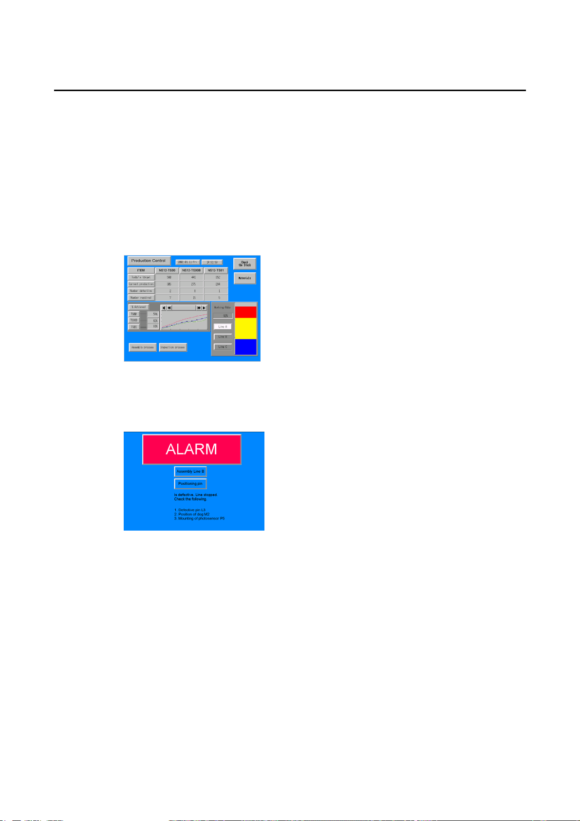
Line Operating Status Monitor Display
NS-series PTs can be used to display information such as the operating status of the system
and the devices. Graphs and other indicators can be used to better represent the information
and make it easy to understand.
Directions for FA Site Operators
The PTs can be used to inform the operators of system and device errors and assist them in
taking appropriate measures.
1-2
Page 24
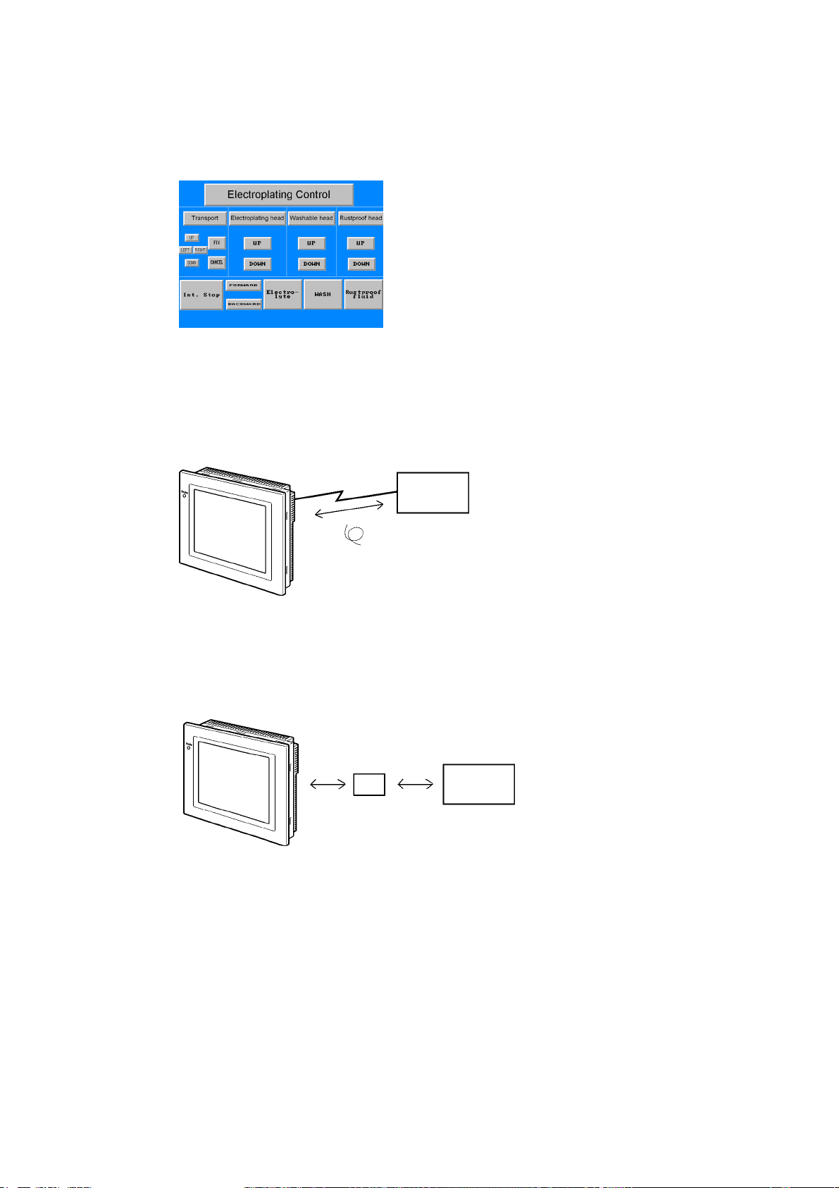
Control Panel Switches
The NS-series PTs allow the user to create various on-screen switches. By using touch
switch inputs, operating results can be sent to the host.
1-1-2 NS-series PT Operating System
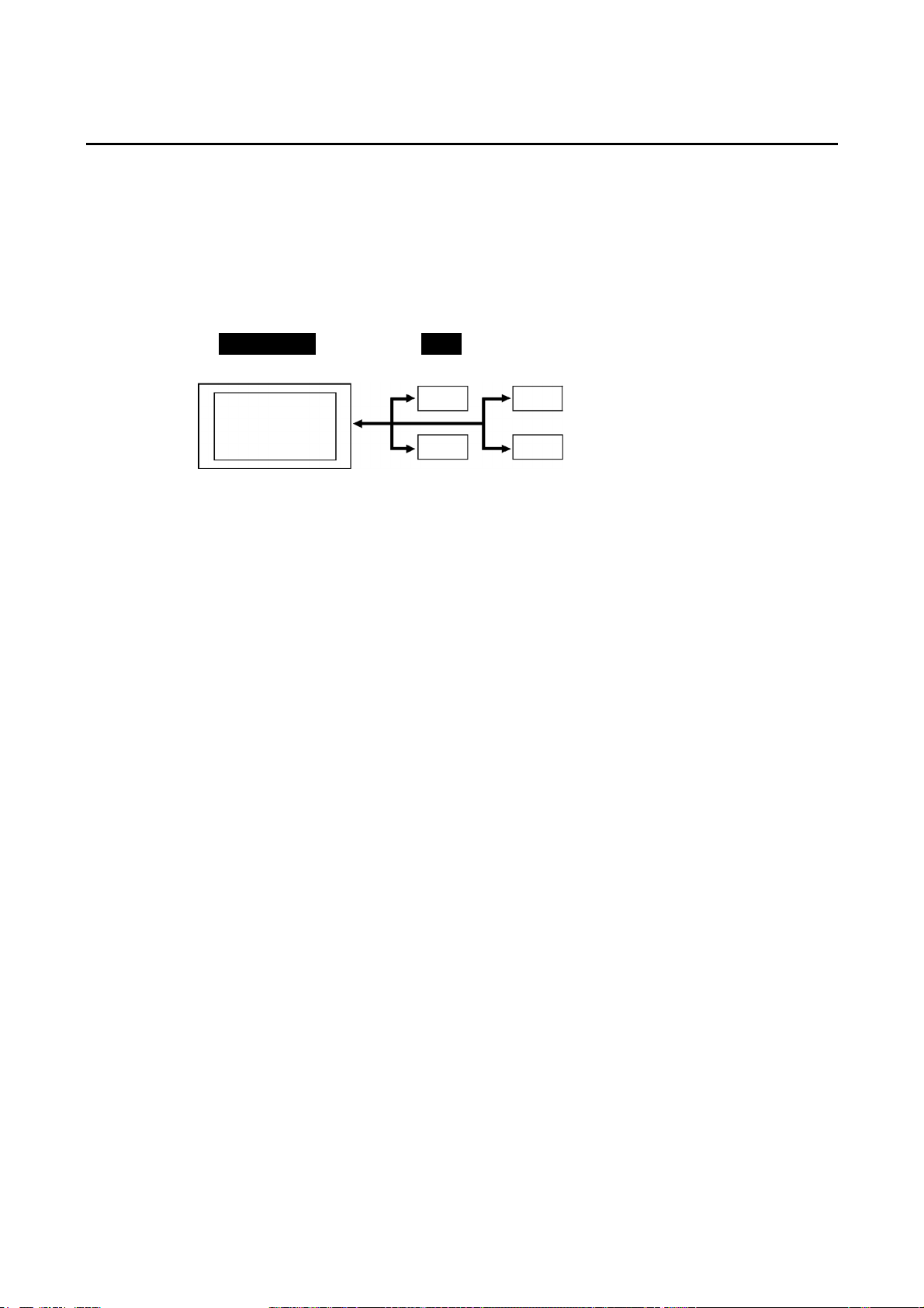
Transferring Screen Data
The screen data displayed on NS-series PTs is created using the CX-Designer on a computer and transferred to the PT through RS-232C, Ethernet, or USB communications.
RS-232C, Ethernet,
USB
Create screen data.
Computer
(CX-Designer)
1-1 NS-series PT Functions and Operation
Screen data
Connect the computer to the PT only
when transferring screen data to or from
the CX-Designer.
Note 1: Some models do not support Ethernet.
Note 2: USB data transfer is not supported for some PT lots and system program versions.
Note 3: If the serial port protocol is set to Allen-Bradley DF1, you cannot connect to the CX-Designer
through that port.
Screen data can also be transferred at high speed using a Memory Card.
Memory
Card
Computer
(CX-Designer)
1-3
Page 25
1-1 NS-series PT Functions and Operation
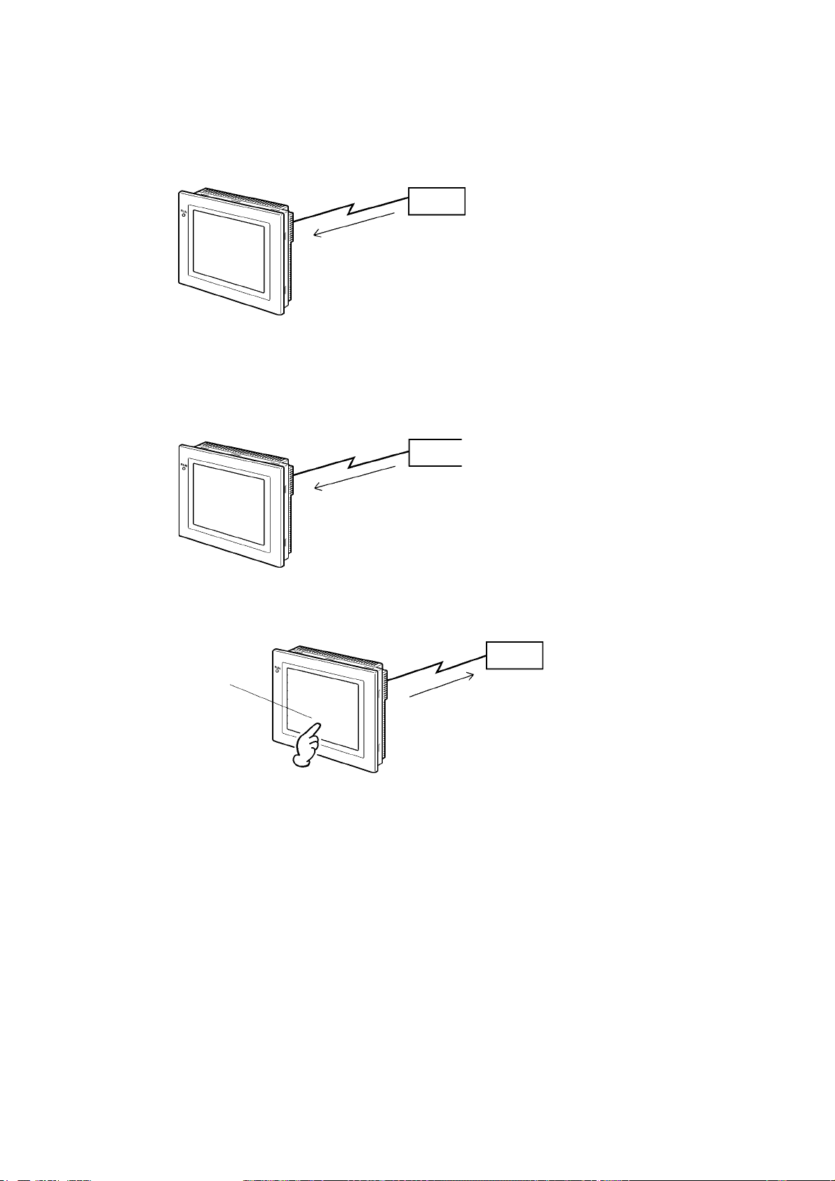
Displaying Screens
The information displayed on the screens is created using the CX-Designer on a computer
and transferred to the PT. The required screens can be displayed by using commands from
the host or touch switch operations.
Reading Data from the Host
A communications method such as NT Link Ethernet or Controller Link is used to connect the
host, and the required data is automatically read from the host.
Note: Some models do not support Ethernet or Controller Link.
NT Link or Ethernet,
Controller Link
Host
The required screens can
be displayed by using
commands from the host
or touch switch operations.
Host
Sending Data to the Host
Data input using touch switches (button ON/OFF status, numerals, and character strings) is
sent to the host.
Host
Touch panel
ON/OFF status,
numeric data, etc.
1-4
Page 26
1-2 Communications with the Host
NS-series PTs allow the user to allocate words and bits in any PLC area for use in accessing
the required display contents and storing input data.
Operations that can be performed include reading and writing allocated word contents and bit
status directly, changing the display status of functional objects on the PT screen, and controlling and notifying PT status.
The NS-series PTs also enable communications with more than one PLC. A host name is
registered for each PLC connected, allowing access to any PLC areas by specifying the host
name and address.
NS - Series PT PLC
DM Area I/O Area
Ti
m
Auxiliary Area
When using NS-series PTs, the host can be connected using any of the following methods.
• 1:1 NT Link
• 1:N NT Link (normal or high-speed)
• Ethernet
• Controller Link
• Host Link
• Other methods, such as temperature controller protocols
• EtherNet/IP
ers/counters
1-2 Communications with the Host
1-5
Page 27

1-2 Communications with the Host
1-2-1 What is an NT Link?
An NT Link is a method for high-speed communications between an OMRON PLC and an
OMRON Programmable Terminal (PT) using a special protocol. In addition to a 1:1 NT Link,
where a single PT is connected to a single PLC, NS-series PTs also support 1:N NT Links,
allowing up to eight PTs to be connected to a single PLC port.
CS- and CJ-series PLCs can also be connected using high-speed 1:N NT Link communications. For details on the PLCs that support high-speed 1:N NT Link communications, refer to
Appendix 8 Standard Models.
In the rest of this manual, "NT Link" refers to NT Link communications in general, "1:1 NT
Link" refers to an NT Link in a 1:1 configuration only, and "1:N NT Links" refers to NT Links in
a 1:N configuration only. Where necessary, "normal 1:N NT Links" and "high-speed 1:N NT
Links" are used. When "1:N NT Links" is used alone, it refers to both normal and high-speed
communications.
1-2-2 Ethernet
Ethernet Units in PLCs that are supported by the NS-series PTs can be used to read and
write data, word, and bit information simply. The use of FINS (Factory Interface Network Service) message communications, one of OMRON’s standard communications services, enables high-speed communications without the need to be aware of the protocol.
For details on connection methods, refer to Section 5 Connecting
Controller Link. For details on the PLCs that can be connected to the Ethernet, refer to Appendix 8 Standard Models.
to Host via Ethernet or
1-2-3 Controller Link
Controller Link is an FA network that can send and receive large data packets among
OMRON PLCs and FA computers. Controller Link Units for PLCs that are supported by the
NS-series PTs connected to NS-CLK21 Controller Link Interface Units can be used to read
and write data, word, and bit information simply.
The Controller Link supports data links that enable data sharing and a message service that
enables sending and receiving data when required.
For details on connection methods, refer to Section 5 Connecting
Controller Link. For details on the PLCs that can be connected using Controller Link, refer to
Appendix 8 Standard Models.
Note: Controller Link Interface Units are compatible only with the NS12 and NS10.
1-2-4 Host Link
Host Link is a serial communications protocol for connecting an OMRON PT 1:1 to a host (a
PLC) to read and write bits and words from the host. Host Link communications connect a PT
to many different PLCs. Refer to the Host Connection Manual (Host Links) for connection
methods and the PLCs for which Host Links can be used.
1-2-5 Connecting to a Temperature Controller
OMRON Temperature Controllers can be connected with an RS-485 connection.
Attach a CJ1W-CIF11 RS-422A Converter to serial port A or B to convert the communications
protocol to RS-485. For details, refer to the Host Connection Manual (Temp. Control, Mem-
Link).
to Host via Ethernet or
1-6
Page 28

1-2-6 Memory Link Connections
When the host is a computer instead of a PLC, the Memory Link protocol can be used to
connect with the computer. Use serial port A or B to connect to the host. For details, refer to
the Host Connection Manual (Tem.Control, MemLink).
1-2-7 Communicating with Other Devices
The NS-series PTs can communicate with the following devices.
• OMRON Trajexia Motion Controllers
• Mitsubishi FX-series, A-series, and Q-series PLCs
• Siemens S7-300-series PLCs
• Yaskawa MP-series Machine Controllers
• Yaskawa F7-series Varispeed and VS Mini V7-series Inverters
• Rockwell Automation (Allen-Bradley) SLC50, MicroLogix, PLC-5, CompactLogix,
CompactLogix, and ControlLogix Controllers
• Devices that support Modbus RTU
For details on connection methods, refer to the Host Connection Manual (Multivendor Connection).
1-2 Communications with the Host
1-2-8 EtherNet/IP
EtherNet/IP is a multi-vendor industrial network protocol that uses Ethernet. The specification is an open standard managed by the ODVA (Open DeviceNet Vendor Association), as is
DeviceNet, and it is used for a variety of industrial devices.
NS-series PTs can communicate with CS/CJ-series EtherNet/IP Units and CJ2H CPU Units,
which have a built-in EtherNet/IP port. Also, it is possible to perform tag message communications if an NS-series PT is connected to a CJ2H PLC. The CJ2H has a tag name server in
the CPU Unit, so if a tag name and address table is stored in advance, it is possible to
perform access from the NS-series PT using only the tag name.
1-7
Page 29
1-3 System Configuration
1-3 System Configuration
The following information describes the system configuration using NS-series PTs. Refer to
Appendix 8 Standard Models for details on available models.
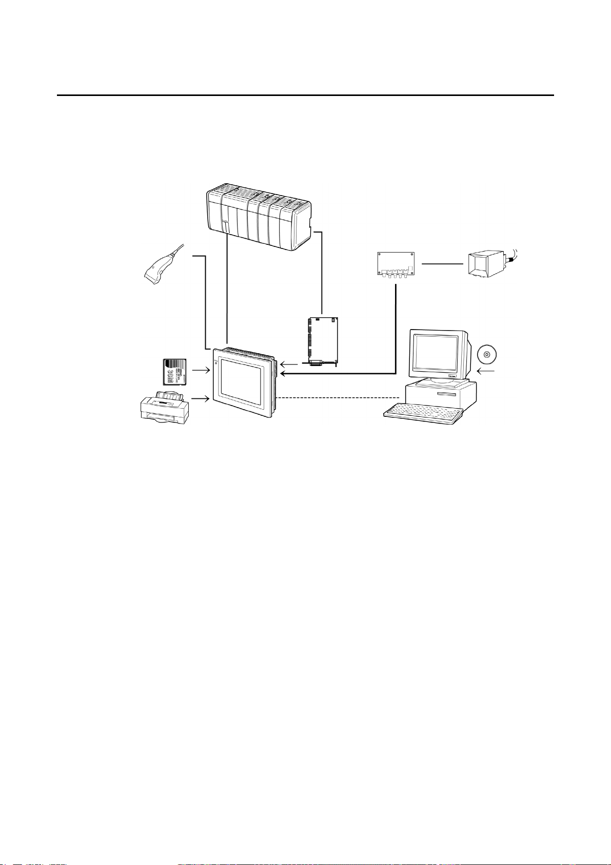
1-3-1 Supported Peripheral Devices
Host
Bar Code Reader
Read bar codes as
text string data.
Memory Card
Save screen data or
the system program or
automatically read data
at startup.
NS-series PT
Printer (See note 4.)
Connecting a general-purpose color
printer to the USB port on an
NS-series PT makes it possible to
print out the current PT display.
RS-232C cable (15 m max.)
RS-422A cable (500 m max.)
RS-232C/422A Adapter
Ethernet cable (See note 1.)
Twisted-pair cable
RS-232C cable
Ethernet cable
(See note 1.)
USB cable
(See note 5.)
Controller Link
Interface Unit
Enables
Controller Link
communications
with a host.
(See note 2.)
Video Input Unit
(See note 3.)
NTSC/PAL cable
Personal computer
Computer running Windows 2000
or XP
Video camera or
Vision Sensor
CX-Designer
Note 1: Only the following models support Ethernet: NS12-TS01(B)-V@, NS10-TV01(B)-V@,
NS8-TV@1(B)-V@, NS5-SQ@1(B)-V@, NS5-TQ@1(B)-V@, and VS5-MQ@1(B)-V@.
Note 2: Only the following models support the Controller Link Interface Unit: NS12-TS0@, NS10-TV0@.
(The NS8 and NS5 do not support the Controller Link Interface Unit.)
Note 3: The following models support the Video Input Unit: NS12-TS0@, NS10-TV0@, and
NS8-TV@@. (The NS5 does not support the Video Input Unit.)
Note 4: The NS5-SQ@@(B)-V@, NS5-TQ@@(B)-V@, and NS5-MQ@@(B)-V@ cannot be connected
directly to general-purpose printers.
Note 5: Refer to 3-3-2 Connecting via USB for information on connecting the PT and computer with a
USB cable.
1-8
• PTs (Refer to Appendix 8 Standard Models.)
• Recommended Bar Code Reader (Refer to page 3-14.)
OMRON V520-RH21-6
OMRON V400-H111
OMRON V400-H211
• RS-232C/422A Converters
OMRON NS-AL002 (non-insulated) (Refer to Appendix 3 Using NS-AL002 Converters.)
OMRON NT-AL001 (insulated) (Refer to Appendix 4 Using NT-AL001 Converters.)
OMRON CJ1W-CIF11
Page 30

1-3 System Configuration
• Recommended Memory Cards (Refer to 3-6 Using Memory Cards.)
Model Memory capacity Memory type
HMC-EF183 128 MB Flash memory
HMC-EF283 256 MB Flash memory
HMC-EF583 512 MB Flash memory
• CX-Designer (Refer to the CX-Designer Online Help.)
NS-CXDC1-V@ (CD-ROM version)
• Video Input Unit (Refer to 3-7 Installing the Video Input Unit.)
NS-CA001
NS-CA002: Refer to the NS Series RGB and Video Input Unit Operation Manual (Cat. No.
V086).
• Controller Link Interface Unit (Refer to 3-8 Installing the Controller Link Interface
Unit.)
NS-CLK21
• USB-compatible Printers (Refer to 3-5 Connecting to Printers.)
• Attachments (Refer to A-9-8 Attachments: NS12-ATT01(B)/
NS12-ATT02/NS8-ATT01/NS8-ATT02.)
Use an Attachment when replacing NT-series PTs.
NS12-ATT01(B)
NS12-ATT02
NS8-ATT01
NS8-ATT02
Reference
Transparent Protective Covers NS12-KBA05N (For NS12 and NS10)
Chemical-resistant Cover NT30-KBA01 (For NS5)
The following optional products are available. (Refer to Appendix 9 List of Optional
Products.)
Anti-reflection Sheets NS12-KBA04 (For NS12 and NS10)
(5 sheets) NS7-KBA04 (For NS8)
NT30-KBA04 (For NS5)
Protective Covers NS12-KBA05 (For NS12 and NS10)
(anti-reflection coating) NS7-KBA05 (For NS8)
(5 covers) NT31C-KBA05 (For NS5)
(5 covers) NS7-KBA05N (For NS8)
NT31C-KBA05N (For NS5)
(1 cover)
Replacement Battery CJ1W-BAT01 (For NS12, NS10, NS8 and NS5)
1-9
Page 31

1-4 Procedure for Running NS-series PTs
3-6
-
3-4
1-4 Procedure for Running NS-series PTs
Use the following procedure to start up the NS-series system.
Host
Host settings
Refer to following pages.
1:1 NT Link: 4-2 and A-8
1:N NT Link: 4-7 and A-9
High-speed 1:N NT Link:
4-15 and A-9
Ethernet: Section 5
EtherNet/IP: Section 5
Controller Link: Section 5
Host Link:
Refer to the Host Connection
Manual (Host Links).
Temperature Controllers:
Refer to the Host
Connection Manual
(Temp. Control, MemLink).
Memory Links:
Refer to the Host
Connection Manual:
(Temp. Control, MemLink).
Other Devices:
Refer to the Host
Connection Manual
(Multivendor Connection).
PT connections
Programming
PT
Panel installation
Refer to Page
Peripheral connections
Power connections
Refer to Page 3-5.
Power ON
System program
installation
Data initialization
Refer to 6-2-1 Screen
Data Area Form at.
System menu settings
Refer to Section 6-1 Operating
Modes and System Menu.
Host connections
RS-232C: Section 4
Ethernet: Section 5
Controller Link: Section 5
EtherNet/IP: Section 5
Settings/com check
Screen transfer
Refer to
.
3 Transferring Datawith Memory Cards.
See
note
1.
See
note
2.
See
note
3.
See note 4.
CX-Designer
Installation on the
computer
Refer to the CX-Designer
User’s Manual.
Screen creation
Refer to NS-series PT
Programming Manual
and the CX-Designer
User’s Manual.
Operation
System maintenance
See note 5.
Connecting to Other Devices
Note 1. RUN mode is entered automatically if screen data already exists.
An error message is displayed if screen data does not exist. Transfer screen data from either
the CX-Designer or a Memory Card.
2. The system program is installed in special situations only, such as when the system program
is being changed or recovered.
3. The system menu can be operated as required to initialize data saved in the PT.
4. The system menu can be displayed by pressing two of the four corners of the touch panel.
5. When errors occur during operation, check I/O and setting statuses as required.
1-10
Page 32

1-4 Procedure for Running NS-series PTs
The following table lists the device and software manuals used for reference.
Device/Software Manual name Catalog No.
NS-series PTs
Setup Manual
(Provides information on existing NS-series models, i.e.,
NS12, NS10, and NS7.)
Programming Manual V073
Macro Reference Provided with
CX-Designer User’s Manual V099 CX-Designer
CX-Designer Online Help Provided with the
NS-series Ladder
NS-series Ladder Monitor Operation Manual Provided with
Monitor
PLC
SYSMAC C200HS Installation Guide W236
SYSMAC C200HS Operation Manual W235
SYSMAC C200HX/HG/HE(-Z) Installation Guide W302
SYSMAC C200HX/HG/HE Operation Manual W303
SYSMAC C200HX/HG/HE(-ZE) Operation Manual W322
SYSMAC CQM1 Operation Manual W226
SYSMAC CQM1H Operation Manual W363
SYSMAC CV Series CV500/CV1000/CV2000/CVM1 Programming Manual: Ladder Diagrams
SYSMAC CPM1A Operation Manual W317
SYSMAC CPM2A Operation Manual W352
SYSMAC CPM1/CPM1A/CPM2A/CPM2C/SRM1(-V2)
Programming Manual
SYSMAC CPM2C Operation Manual W356
CP-series CP1H/CP1L CPU Unit Programming Manual W451
CP-series CP1L CPU Unit Operation Manual W462
CP-series CP1H CPU Unit Operation Manual W450
SYSMAC CJ Series Operation Manual W393
SYSMAC CS/CJ Series Serial Communications Unit and
Board Operation Manual
SYSMAC CS Series Operation Manual W339
SYSMAC CS/CJ Series Programming Manual W394
SYSMAC CS/CJ Series Instruction Reference Manual W340
SYSMAC CS/CJ Series Programming Console Operation
Manual
SYSMAC CS/CJ Series Communications Command Ref-
erence Manual
Programming
Devices/Software
SYSMAC Support Software Operation Manual: C-series
PLCs
SYSMAC Support Software Operation Manual: CVM1
PLCs
SYSMAC CPT Operation Manual W333
CX-Programmer User Manual W437
Ethernet Unit
SYSMAC CS/CJ Series Ethernet Unit Operation Manual W343
SYSMAC CVM1/CV Series Ethernet Unit System Manual W242
FINS Command Reference Manual W227
SYSMAC CS and CJ Series Ethernet Units Operation
Manual Construction of Networks
SYSMAC CS and CJ Series Ethernet Units Operation
Manual Construction of Applications
Controller Link Support Board Operation Manual W307 Controller Link Support Board
Controller Link Support Board for PCI Bus Operation
Manual
Controller Link Unit Controller Link Unit Operation Manual W309
EtherNet/IP SYSMAC CS/CJ/NE1S Series EtherNet/IP Unit Operation
Manual
V072
CX-Designer
CX-Designer.
NS-series Ladder
Monitor
W202
W353
W336
W341
W342
W248
W249
W420
W421
W383
Z909
1-11
Page 33

1-4 Procedure for Running NS-series PTs
1-12
Page 34

Section 2
Before Connecting
This section provides information on methods for connecting NS-series PTs that must be understood before connecting the host and peripheral devices.
For details on connecting through host link communications, refer to the Host Connection
Manual (Host Link). For details on Temperature Controller connections and Memory Link
communications, refer to the Host Connection Manual (Temp. Control, MemLink). For details
on connecting to other devices, refer to the Host Connection Manual (Multivendor Connection).
2-1 Connecting the Host ........................................................................................................ 2-2
2-1-1 Communications Types and Connection Methods ................................................... 2-2
2-2 Part Names and Functions ............................................................................................... 2-8
Page 35

2-1 Connecting the Host
2-1 Connecting the Host
This section provides details on the networks for hosts that can be used with NS-series PTs.
2-1-1 Communications Types and Connection Methods
• Communications Ports and Methods
All NS-series PTs have two serial ports each. The NS12-TS01(B)-V1/-V2, NS10-TV01(B)V1/-V2, NS8-TV@1(B)-V1/-V2, NS5-SQ01(B)-V1, NS5-SQ@1(B)-V2, NS5-TQ@1(B), and
NS5-MQ@1(B)-V2 each have one Ethernet interface.
A Controller Link Interface Unit can also be mounted to the NS12-TS0@(B)-V1 or NS10TV0@(B)-V1 to enable Controller Link communications. These communications ports and interfaces can be used for the communications methods shown in the following table.
Communications ports Supported communications methods
1:1 NT Link
Serial port A
Serial port B (See note 2.)
Ethernet interface
Controller Link Interface
Unit (See note 3.)
Note 1: A 1:N NT Link can be set for either normal or high-speed communications.
Note 2: With the NS5, EXP. (Expansion) I/F on the Comm Tab Page in the System Menu settings
can be set to use a communications port in the expansion interface connector. The expansion interface, however, is a future expansion, which cannot yet be used. Always use the serial port B connector. Communications will not be possible on serial port B if the expansion
interface is selected in the System Menu settings.
Note 3: Controller Link Interface Units are compatible only with the NS12 and NS10.
The following table shows the possible combinations of communications methods when serial
ports A and B are connected to the host at the same time.
Using serial ports A and B at the same time Supported/not supported
1:1 NT Link + 1:1 NT Link Supported
1:1 NT Link + 1:N NT Links Supported
1:N NT Links + 1:N NT Links Supported
1:N NT Links (See note 1.)
For connecting the CX-Designer and for Bar Code Reader input.
1:1 NT Link
1:N NT Links (See note 1.)
For connecting the CX-Designer and for Bar Code Reader input.
FINS communications
EtherNet/IP
For connecting the CX-Designer.
FINS communications
Data links
2-2
• Converting Communications Type Using RS-232C/RS-422A Converter
OMRON’s NS-AL002 RS-232C/RS-422A Converter can be used to convert the communications type between RS-232C and RS-422A.
• Communications Type and Connection Method Combinations
The following table shows the possible connection methods for each communications type.
Page 36

1:1 Connection
PT
commu-
nications
type
RS-232C
commu-
nications
RS-232C
RS-422A
Host
type
Supported connection methods
PT
RS-232C cable
PT
NS-AL002
Converter
RS-422A cable
Host
Host
2-1 Connecting the Host
Supported communications
methods
1:1
NT
Link
1:N
NT
Links
FINS
EtherNet/IP
Data
Links
Yes Yes No No No
Yes Yes No No No
Refer-
ence
page
P.4-2
P.4-10
P.4-2
P.4-10
PT
10Base-T/100Base-T twisted-pair cross
Ethernet
cable
Controller Link
PT
Inte rface Unit
Specified s hielded twisted-pair
cable
Host
No No No Yes No P.5-26
Host
No No Yes No Yes P. 5-15
Ethernet
Controller
Link (See
note.)
Ethernet No No Yes No No P.5-2
EtherNet/
IP
Controller
Link
Yes: Connection is possible. No: Connection is not possible.
Note: Only when a Controller Link Interface Unit (NS-CLK21) is mounted.
2-3
Page 37

2-1 Connecting the Host
1:N Connection (Connecting Multiple PTs to a Single Host)
PT
commu-
nications
type
RS-232C RS-422A
Ethernet
nications
Ethernet No No Yes No No P.5-2
Host
commu-
type
Supported connection methods
PTs
NS-AL002
Adapter
RS-422A cable
PTs
Ethernet
10Base-T/100Base-T
twisted-pair straight cable
HUB
Host
Host
Supported communications
1:1
NT
Link
1:N
NT
Links
methods
Ether-
FINS
Net/IP
Data
Links
Refer-
ence
page
No Yes No No No P.4-10
EtherNet/
IP
No No No Yes No P.5-26
Controller
Link (See
note.)
PTs
Controller
Link
Controller Link
Interface Unit
Specified shielded
twisted-pai r cable
Host
No No Yes No Yes P. 5-15
Yes: Connection is possible. No: Connection is not possible.
Note: Only when a Controller Link Interface Unit (NS-CLK21) is mounted.
2-4
Page 38

N:1 Connection (Connecting Multiple Hosts to a Single PT)
p
NS-
series
PT
commu-
nications
RS-232C RS-232C
Host
commu-
Supported connection methods
nications
PT
Host
Serial port A
RS-232C cable
Host
Serial port B
RS-232C cable
Ethernet No No Yes No No P.5-2
PT
Host
2-1 Connecting the Host
Supported communications
methods
1:1
NT
Link
1:N
NT
Links
FINS
EtherNet/IP
Data
Links
Yes Yes No No No
Refer-
ence
page
P.4-2
P.4-10
HUB
Ethernet
EtherNet/
IP
Ethernet
10Base-T/100Base-T
twisted-
air straight cable
Host
No No No Yes No P.5-26
PT
Controller
Link (See
note.)
Controller
Link
Controller Link
Interface Unit
Specifi ed shielded
twisted-p air cable
Host
No No Yes No Yes P. 5-15
Host
Yes: Connection is possible. No: Connection is not possible.
Note: Only when a Controller Link Interface Unit (NS-CLK21) is mounted.
2-5
Page 39

2-1 Connecting the Host
NS-
series
PT
commu-
nications
RS-232C
Ethernet,
RS-232C
Host
communi-
cations
RS-232C,
RS-422A
Ethernet,
EtherNet/IP,
RS-232C
Supported connection methods
PT
Host
Serial port A
NS-AL002
RS-232 C/
RS-422 A
Convert er
RS-232C cable
Host
Serial port B
RS-422A cable
An RS-422A line can be connected to
serial port A at the same time that an RS232C line is connected to serial port B.
PT
Ethernet
10Base-T/100Base-T
twisted-pair cross c able
Host
Host
Supported communica-
tions methods
1:1 NT
Link
1:N NT
Links
FINS
EtherNet/IP
Yes Yes No No
Yes Yes Yes Yes
Refer-
ence
page
P.4-2
P.4-10
P.4-2
P.4-10
P.5-2
RS-232C cable
Yes: Connection is possible. No: Connection is not possible.
Note: Only when a Controller Link Interface Unit (NS-CLK21) is mounted.
• The NS-AL002 is connected directly to the serial port of the PT and power is supplied
from pin 6 of the port.
• When there are multiple serial ports and Ethernet Units for a single host, each port can
be used to communicate with separate PTs. This type of communications method,
however, will reduce the communications performance at the host.
2-6
Page 40

k
NS-
series
PT
commu-
nications
Host
commu-
nications
Supported connection methods
PT
2-1 Connecting the Host
Supported communications
methods
1:1
NT
Link
1:N
NT
Links
FINS
EtherNet/IP
Data
Links
Refer-
ence
page
RS-232C,
Controller
Link
Ethernet,
Controller
Link
RS-232C,
Controller
Link
Ethernet,
EtherNet/
IP,
Controller
Link
Serial port A
Controller Link
Interface Unit
Specified shielded twis ted-pair cable
PT
Controller Link
Specified shielded twisted-pair cable
RS-232C cable
Controller Link
Ethernet
10BASE-T/ 100BASE-T
Twisted-pair cross cable
Controller Lin
Host
Host
Host
Host
Yes Yes Yes Yes Yes
No No Yes Yes Yes
Yes: Connection is possible. No: Connection is not possible.
Note: Only when a Controller Link Interface Unit (NS-CLK21) is mounted.
• The NS-AL002 is connected directly to the serial port of the PT and power is supplied
from pin 6 of the port.
• When there are multiple serial ports and Ethernet Units for a single host, each port can
be used to communicate with separate PTs. This type of communications method,
however, will reduce the communications performance at the host.
P.4-2
P.4-10
P.5-26
P.5-2
P.5-15
P.5-26
2-7
Page 41

2-2 Part Names and Functions
2-2 Part Names and Functions
The part names and functions of the PT are described here.
NS12/NS10
Front Panel
RUN Indicator
Status
RUN indicator
Lights or flashes to indicate
the status of the PT.
Indicator Green Orange Red
Lit PT is operating normally. • The file system check that is per-
Flashing Memory Card transfer ended
normally.
A backlight error occurred
immediately after power was
turned ON.
Not lit • Power is not being supplied to the PT.
• The fuse is broken.
• The system program is damaged and the system cannot be booted.
Display
NS12: 12.1-inch TFT high-luminance LCD
NS10: 10.4-inch TFT high-luminance LCD
The entire display is a touch panel that serves as
an input device.
formed immediately after the power
is turned ON is in progress.
• The battery power is low, or the bat-
tery is not connected and the PT is
operating normally.
Memory Card transfer in progress. Memory Card
An error occurred at
startup.
transfer ended
abnormally.
2-8
Page 42

2-2 Part Names and Functions
r
r
r
r
r
r
r
NS12/NS10 Rear Panel Switches
Expansion Interface Connecto
Used to mount the Video Input
Unit or the Controller Link
Interface Unit.
Memory Card Connecto
Used to connect the
memory card for storing
and transmitting screen
data, log data, and system
programs.
DIP Switch
Used to set the settings for
transmitting data using the
Memory Card.
Reset Switch
Used to initialize the PT.
The status of screen data,
other registered data, and
the system menu, however,
will not change.
Main Circuit DC
Input Terminals
Used to connect
the power supply.
FG Terminal
Used to prevent
malfunctions due to
noise interference.
USB Host Connecto
Used to connect to printers. It is a
USB Type A connector.
Refer to 3-5-1 Connecting to a
Printer Compatible with ESC/P
Raster or BJ Raster.
Power Input Terminal Block Cove
Covers the power input terminal block.
Note
Battery Cove
The battery is installed
underneath the cover.
Serial Port B Connector
Used to connect the host, CXDesigner, and Bar Code Reader.
Uses an RS-232C 9-pin
connector.
USB Slave Connecto
This is a USB Type B connector. It can be used to connect to the
CX-Designer. Refer to 3-3-2 Connecting via USB.
Serial Port A Connector
Used to connect the host, CX-Designer, and
Bar Code Reader. Uses an RS-232C 9-pin
connector.
Ethernet Connecto
Used to connect the Ethernet cable. Uses a
10Base-T/100Base-T 8-pin modular plug.
Confirm system safety before turning the power ON/OFF or restarting. Otherwise the system
may operate unpredictably.
2-9
Page 43

2-2 Part Names and Functions
NS8 Front Panel
Display
NS8-TV@@-V2: P8.4-inch TFT high-
luminance color LCD
NS8-TV@@-V1: P8.0-inch TFT high-
luminance color LCD
The entire display is a touch panel that
serves as an input device.
RUN indicator
Lights or flashes to indicate the
status of the PT.
RUN Indicator Status
Indicator Green Orange Red
Lit PT is operating normally. • The file system check that is
performed immediately after the
power is turned ON is in
progress.
• The battery power is low, or the
battery is not connected and the
PT is operating normally.
Flashing Memory Card transfer ended
normally.
Not lit • Power is not being supplied to the PT.
• The fuse is broken.
• The system program is damaged and the system cannot be booted.
Memory Card transfer in progress. Memory Card
An error
occurred at
startup.
transfer ended
abnormally.
2-10
Page 44

NS8 Rear Panel
p
Expansion Interface Connector
Used to mount the Video Input
Unit or the Controller Link
Interface Unit.
2-2 Part Names and Functions
Memory Card Connector
Used to connect the
memory card for storing
and transmitting screen
data, log data, and system
programs.
DIP Switch
Used to set the settings for
transmitting data using the
Memory Card.
Reset Switch
Used to initialize the PT.
The status of screen data,
other registered data, and
the system menu, however,
will not change.
Battery Cover
The battery is installed
underneath the cover.
Main Circuit DC
Input Terminals
Used to connect
the
ower supply.
FG Terminal
Used to prevent
malfunctions due to
noise interference.
USB Host Connector
Used to connect to printers.
It is a USB Type A connector.
Refer to 3-5-1 Connecting to
a Printer Compatible with
ESC/P Raster or BJ Raster.
Power Input Terminal Block Cover
Covers the power input terminal
block.
USB Slave Connector
This is a USB Type B connector.
Refer to 3-3-2 Connecting via USB. It is used to connect to CX-Designer.
Serial Port B Connector
Used to connect the host, CXDesigner, and Bar Code Reader.
Uses an RS-232C 9-pin
connector.
Ethernet Connector
Used to c onnect the Ether net cable. Uses a
10Base-T/100Base-T 8-pin modular plug.
Serial Port A Connector
Used to connect the host, CX-Designer, and
Bar Code Reader. Uses an RS-232C 9-pin
connector.
Confirm system safety before turning the power ON/OFF or restarting. Otherwise the system
Note
may operate unpredictably.
2-11
Page 45

2-2 Part Names and Functions
NS5 Front Panel
RUN indicator
Lights or flashes to indicate
the status of the PT.
Display
5.7-inch STN color LCD
The entire display is a touch panel that
serves as an input device.
Colors may be lighter toward the edge
of the screen.
This is characteristic of STN displays
and not an error.
RUN Indicator Status
Indicator Green Orange Red
Lit PT is operating normally. • The file system check that is
performed immediately after the
power is turned ON is in
An error
occurred at
startup.
progress.
• The battery power is low, or the
battery is not connected and the
PT is operating normally.
Flashing Memory Card transfer ended
normally.
Memory Card transfer in progress. Memory Card
transfer ended
abnormally.
Not lit • Power is not being supplied to the PT.
• The fuse is broken.
• The system program is damaged and the system cannot be booted.
2-12
Page 46

NS5 Rear Panel
r
2-2 Part Names and Functions
Local Bus Interface Connector
Used to connect to an Expansion Interface Unit.
(Applicable with NS Ver. 6 or higher systems.) Current
Expansion Interface Units (NS-CA001, NS-CA002, and
NCCKL21) cannot be connected.
FG Terminal
Used to prevent malfunctions
due to noise interference.
Main Circuit DC Input Terminals
Used to connect the power supply.
DIP Switch
Used to set the settings for
transmitting data using the
Memory Card.
Reset Switch
Used to initialize the PT. The status
of screen data, other registered data,
and the system menu, however, will
not change.
Serial Port B Connector
Used to connect the host, CXDesigner, and Bar Code Reader.
Uses an RS-232C 9-pin connector.
Confirm system safety before turning the power ON/OFF or restarting. Otherwise the system
Note
may operate unpredictably.
Battery Cove
The battery is installed
underneath the cover.
Serial Port A Connector
Used to connect the host, CXDesigner, and Bar Code Reader.
Uses an RS-232C 9-pin connector.
Ethernet Connector
Used to connect the Ethernet cable.
Uses a 10Base-T/100Base-T 8-pin
modular plug.
USB Slave Connector
This is a USB Type B connector.
Refer to 3-3-2 Connecting via
USB.
USB Slave Connector
This is a USB Type B connector.
Refer to 3-3-2 Connecting via USB.
2-13
Page 47

2-2 Part Names and Functions
Touch Panel
The touch switches on the front panel of the PT are used to perform input operations. Press
the touch switches to perform operations such as switching screens and sending bit status to
the host.
Function
performed
To ensure correct input operations, create touch switches so that they consist of at least two
switches horizontally and vertically.
• Press the touch switches with a pressure of 30 N max.
Note
• Do not press the touch switches when the backlight is not lit or when there is no display.
• Check system safety before pressing the touch switches.
• Inputs may not be recognized if the touch switches are pressed in rapid succession. Check
that one input operation has finished before performing the next one.
Minimum Switch Size
NS12: 16 dots (4.92 mm)
NS10: 16 dots (5.3 mm)
NS8-V1: 20 dots (4.78 mm) × 20 dots (4.78 mm)
NS8-V2: 20 dots (4.86 mm)
NS5: 16 dots (5.8 mm) × 16 dots (5.8 mm)
Functional objects can be created combining
minimum size switches.
When a functional object is pressed, its function is performed.
× 16 dots (4.92 mm)
× 16 dots (5.3 mm)
× 20 dots (4.86 mm)
Reference
• Pressing Three Switches Simultaneously
When the positions of multiple touch switches are set as shown in the example and
three switches are pressed simultaneously, the touch switches will malfunction due to
structural characteristics.
Position the touch switches carefully. In the example shown below, switches have
been created in positions A and B, and at points C and D, where the vertical and horizontal lines through A and B intersect.
A C
• If touch switches A, B, and C are turned
ON simultaneously, switch D may also
turn ON due to the structure of the touch
panel.
• In the same way, if touch switches A, B,
Minimum touch switch frame
D B
and D are turned ON simultaneously,
switch C may also turn ON.
2-14
Page 48

2-2 Part Names and Functions
Connector Pin Arrangement of Serial Ports A and B
Pin number Signal name Name
1 NC Not connected.
2 SD Send data
3 RD Receive data
4 RS Request to send
5 CS Clear to send
6 +5V 5-V output (250 mA max.)
7 NC Not connected.
8 NC Not connected.
9 SG Signal ground
Make sure that the total current capacity of devices being supplied power is 250 mA max. be-
Note
fore using the 5-V power supply from pin 6. The capacity of the PT's 5-V output is 250 mA
max. at 5 V ±5%.
Ethernet Connector Pin Arrangement
Pin number Signal name Name
1 TD+ Twisted-pair output (differential output)
2 TD− Twisted-pair output (differential output)
3 RD+ Twisted-pair input (differential input)
4 BI_D+ Protection circuit
5 BI_D− Protection circuit
6 RD− Twisted-pair input (differential input)
7 BI_D+ Protection circuit
8 BI_D− Protection circuit
When using a cable with a hood (or boot), make sure that the length for connection is at least
15 mm, as shown in the following diagram.
15 mm min.
2-15
Page 49

2-2 Part Names and Functions
2-16
Page 50

Section 3
Installing the PT and Connecting
Peripheral Devices
This section describes the methods used to install the PT and connect peripheral devices.
For details on methods for connecting the host, refer to Section 4 Connecting the Host to the
Serial Port or Section 5 Connecting to Host via Ethernet or Controller Link.
3-1 Installing the PT.............................................................................................................. 3-3
3-1-1 Installation Environment........................................................................................... 3-3
3-1-2 Installing RS-232C/RS-422A Converters................................................................. 3-4
3-1-3 Mounting the PT to the Control Panel...................................................................... 3-4
3-1-4 Connecting the Power Supply................................................................................... 3-6
3-1-5 Wiring the Ground Wire........................................................................................... 3-7
3-1-6 Peripheral Device Connection Limitations............................................................... 3-7
3-2 Starting the PT ................................................................................................................ 3-8
3-2-1 Operation at Startup.................................................................................................. 3-8
3-2-2 Starting the PT for the First Time........................................................................... 3-10
3-3 Connecting the CX-Designer ........................................................................................ 3-12
3-3-1 Connecting via RS-232C or Ethernet ..................................................................... 3-12
3-3-2 Connecting via USB ............................................................................................... 3-12
3-3-3 Connecting via a Modem........................................................................................ 3-14
3-4 Connecting to Bar Code Readers .................................................................................. 3-15
3-4-1 Connection Methods............................................................................................... 3-15
3-4-2 Setting Bar Code Readers....................................................................................... 3-16
3-4-3 Data Format ............................................................................................................ 3-17
3-4-4 Bar Code Input ....................................................................................................... 3-17
3-5 Connecting to Printers................................................................................................... 3-18
3-5-1 Connecting to a Printer Compatible with ESC/P Raster and BJ Raster.................. 3-18
3-6 Using Memory Cards.................................................................................................... 3-19
3-6-1 Installation .............................................................................................................. 3-20
3-6-2 Replacing the System Program............................................................................... 3-21
3-6-3 Transferring Data with Memory Cards................................................................... 3-22
Page 51

3-7 Installing the Video Input Unit ..................................................................................... 3-28
3-7-1 Video Input Unit Components................................................................................ 3-28
3-7-2 Nomenclature and Functions .................................................................................. 3-29
3-7-3 Installation Method for Video Input Unit............................................................... 3-30
3-7-4 Connecting to Video Input Connectors................................................................... 3-35
3-8 Installing the Controller Link Interface Unit................................................................. 3-40
3-8-1 Controller Link Interface Unit Components ........................................................... 3-40
3-8-2 Nomenclature and Functions .................................................................................. 3-41
3-8-3 Installation Method for Controller Link Interface Unit .......................................... 3-44
3-8-4 Wiring..................................................................................................................... 3-51
Page 52

3-1 Installing the PT
The methods used to mount the PT to the control panel and connect the power supply are
described here.
3-1-1 Installation Environment
Always mount the PT to the control panel and perform other installation procedures according
to the following precautions.
Note Do not install the PT in any of the following locations:
• Locations subject to extreme temperature changes.
• Locations subject to temperatures or humidity outside the ranges in the specifications.
• Locations subject to high humidity that may result in condensation.
• Locations that would subject the PT to chemicals.
• Locations that would subject the PT to oil.
• Locations subject to corrosive or flammable gases.
• Locations that would subject the PT to direct shock or vibration.
• Locations that would directly expose the PT to wind or rain.
• Locations subject to strong ultraviolet light.
Provide proper shielding measures when installing in the following locations:
• Locations subject to static electricity or other sources of noise.
• Locations subject to strong electromagnetic fields.
• Locations near to power supply lines.
• Locations subject to possible exposure to radiation.
3-1 Installing the PT
When unpacking the PT and peripheral devices, check for any external damage. Shake the
Note
product gently and check for any abnormal sounds.
3-3
Page 53

3-1 Installing the PT
3-1-2 Installing RS-232C/RS-422A Converters
When using RS-232C/RS-422A Converters, mount the PT to the control panel before installing these Units.
For details on installing and removing RS-232C/RS-422A Converters, refer to Appendix 3 Us-
ing NS-AL002 Converters.
3-1-3 Mounting the PT to the Control Panel
The PT is flush-mounted to the control panel.
The PT is mounted using the panel mounting brackets provided with the PT, and tools, such
as a Phillips screwdriver.
Use the following procedure to mount the PT to the control panel.
1. Make a hole in the panel for flush mounting according to the following dimensions and insert the PT from the front of the panel.
Height
Width
Recommended panel thickness:
1.6 to 4.8 mm
Model Dimensions
NS12
NS10
NS8
NS5
Width 302
Width 302
Width 220.5
Width 184
+1
× Height 228
0
+1
× Height 228
0
+0.5
× Height 165.5
0
+0.5
× Height 131
0
+1
+1
+0.5
mm
0
mm
0
+0.5
0
mm
0
mm
3-4
Page 54

3-1 Installing the PT
2. Secure the panel mounting brackets from the back of the panel, as shown in the following
diagram.
Insert the catch on each bracket into the square hole on the PT, and secure the PT to the
panel by tightening the screws with a Phillips screwdriver while gently pulling in the PT.
Note Do not allow metal particles to enter the PT while work is being performed on the panel.
• The allowable thickness of the panel for mounting is between 1.6 and 4.8 mm.
Secure the mounting bracket with a uniform tightening torque of between 0.5 and 0.6 N⋅m
to keep the PT waterproof and dustproof.
The front sheet may become distorted if the tightening torque is more than the specified
limit or not uniform. Always use a panel that is clean, undistorted, and strong enough to
adequately withstand mounting the PT.
Note This product conforms to shipbuilding standards. The shipbuilding standards have conditions
that may make them unusable depending on the location in which the PT is installed. When
using a PT on a ship, be sure to contact your OMRON sales representative.
Shipping Standards (NK, LR, ABS, BV, DNV, KR, GL)
The conditions for use in locations other than the bridge or deck are as follows:
• The NS-series PT must be installed in a control panel.
• The control panel must be equipped with an air conditioner.
• The entire surface of the NS-series PT must be covered with electromagnetic shielding
(specified below) that is also grounded using conductive tape (e.g., copper tape).
• Gaps in the door of the control panel must be completely filled or covered with gaskets or
other material.
• Gaps between the PT and the panel cutout must be completely covered with conductive
tape, such as copper tape, and the PT must be secured using mounting brackets.
The conditions for use on a bridge (Class NK certification only) are as follows:
• The NS-series PT must be installed in a control panel.
• The control panel must be equipped with an air conditioner.
• The entire surface of the NS-series PT must be covered with electromagnetic shielding that
is also grounded using conductive tape (e.g., copper tape).
• Gaps in the door of the control panel must be completely filled or covered with gaskets or
other material.
• Gaps between the PT and the panel cutout must be completely covered with conductive
tape, such as copper tape, and the PT must be secured using mounting brackets.
• The following noise filter must be connected to the 0 to 24 VDC power line.
Electromagnetic Shielding
* Electromagnetic shielding reduces the permeability by approximately 50%.
Noise Filter
Manufacturer SEIWA ELECTRIC MFG, Co., Ltd.
Model E09F-100, E09R13502P
Manufacturer Cosel
Model TAH-06-683
3-5
Page 55

3-1 Installing the PT
3-1-4 Connecting the Power Supply
Connect a 24-VDC power supply to the power input terminals.
Note • Do not connect an AC power supply to the power terminals.
• Use a DC power supply with low voltage fluctuation.
• Do not perform a dielectric strength test.
• To conform to EC Directives, use a DC power supply that will provide a stable output even
if the input is momentarily interrupted for 10 ms, and that has reinforced or double insulation.
• Power Supply
The following table shows the specifications for the power supply that can be connected. Determine power supply specifications that meet the power supply capacity requirements.
Item Value
Power supply voltage 24 VDC
Allowable voltage range 20.4 to 27.6 VDC (24 VDC ±15%)
Power supply capacity 25 W min. (NS5: 15 W min.)
Functional
NS12, 10, 8 NS5
24 VDC
Functional ground
24 VDC
ground
Breaker
24 VDC
power
supply
24 VDC power supply
Breaker
• Parts Used to Connect the Power Supply
Note Connect power to the power terminal block using twisted-pair power lines with a cross-
sectional area of at least 2 mm
The correct tightening torque for the terminal block is 0.8 N⋅m. Tighten terminal block screws
properly.
Forked type Round type
7 mm max.
• Recommended Products
Manufacturer
J.S.T. Mfg. Co., Ltd. 2-YS3A 2-3.5
Fuji Terminal Industry Co., Ltd. 2-YAS3.5 V2-S3.5
Nichifu Terminal Industries Co., Ltd. 2Y-3.5 2-3.5
7 mm max.
2
and always using M3.5 crimp terminals.
Model number of
forked terminals
Model number of
round terminals
Applicable power
lines (twisted-pair)
2.0 to 2.63 mm
2
3-6
Page 56

Note When surge noise occurs in the DC power supply, connect a Transistor Voltage Suppressor
(TVS) between the 24-V and 0-V DC terminals.
Recommended TVS model: 1.5KE33CA
Manufacturers: Vishay Intertechnology Inc, ST Microelectronics
3-1-5 Wiring the Ground Wire
The PT is provided with a functional ground (FG: ) terminal.
Wire the FG terminal according to the following conditions.
1. Ground according to Figure when there is difference in potential between the PT and host.
Do not ground the functional ground of the PT if it is far from the host and one-point
grounding is difficult.
2. Do not ground the functional ground (FG: ) of the PT if it is mounted to the same panel
as devices that generate noise, such as motors and inverters.
PT Host
One-point
grounding
Note Ground correctly to prevent malfunctions caused by noise.
3-1 Installing the PT
3-1-6 Peripheral Device Connection Limitations
Select one of the following combinations when devices requiring power supply are connected
to port A, port B, and an Expansion Interface Unit on the PT. Use a 5-V Bar Code Reader with
a current consumption of 250 mA or the equivalent.
Port A and B connection combinations Expansion Interface Unit
When a Bar Code Reader and the NS-AL002 are connected to ports
A and B at the same time
When a Bar Code Reader and the CJ1W-CIF11 are connected to
ports A and B at the same time
When a Bar Code Reader and the NT-AL001 are connected to ports
A and B at the same time
When the CJ1W-CIF11 and C1W-CIF11 are connected to ports A
and B at the same time
When the CJ1W-CIF11 and NS-AL002 are connected to ports A and
B at the same time
When the CJ1W-CIF11 and NT-AL001 are connected to ports A and
B at the same time
When two NT-AL001s are connected to ports A and B at the same
time
When a Bar Code Reader is connected to port A or B Can be used
When the CJ1W-CIF11 is connected to port A or B Can be used
When the NS-AL002 is connected to port A or B Can be used
When the NT-AL001 is connected to port A or B Can be used
When Bar Code Readers are connected to ports A and B at the
same time
When the NT-AL001 and NT-AL002 are connected to port A or B at
the same time
(NS-CA001, NS-CA002,
NS-CLK21)
Cannot be used
Cannot be used
Cannot be used
Can be used
Can be used
Cannot be used
Cannot be used
Cannot be used
Cannot be used
3-7
Page 57

3-2 Starting the PT
3-2 Starting the PT
Check that the hardware is connected properly, turn ON the power to the PT, and then start
the PT.
3-2-1 Operation at Startup
Use the following procedure to start the PT.
Indicator lights orange.
Immediately after the power is turned ON, the indicator will light orange.
The file system will be checked and the system recovered if the power was turned OFF
while a file was being written in previous operation, or if the battery capacity was low and
drive safety information from the system program area screen data area could not be saved.
↓
When the power is ON or the PT is reset, the PT will operate as follows:
Indicator lights green.
When the system starts properly, the indicator will light green.
If the indicator does not light green, the system programs may be damaged. Contact your
nearest OMRON representative.
↓
Startup message is displayed.
A message about the startup status will be displayed.
If an error occurs, the PT will stop startup procedures and display a message. (Refer to Sec-
tion 5 Troubleshooting in the Programming Manual.)
If an error occurs that allows startup to continue, a warning will be displayed. When a warning is displayed, the PT will enter standby state and wait for touch input. Check the message
and then touch the screen. The PT will continue with startup procedures.
3-8
Page 58

3-2 Starting the PT
↓
PT starts operating
The PT goes into RUN mode and starts operating according to the screen data in the PT.
When the PT is connected using communications conditions other than the set conditions, a
message "Connecting…" will be displayed at the bottom right of the screen, and the PT will
be in standby status until normal connection is established.
To change the communications settings, display the System Menu and change the settings.
Note Confirm the safety of the system before turning the power ON and OFF or pressing the reset
switch.
Reference
If tags are used in the screen data in the NS-series PT, tags will be verified before opera-
tion is started. Refer to 6-11 Verifying Tags for details.
3-9
Page 59

3-2 Starting the PT
3-2-2 Starting the PT for the First Time
Always perform the following operations when turning ON the PT for the first time after purchase.
1. Language selection.
2. Set the date and time.
Operate according to the following conditions.
a) When the power is turned ON to the PT, the following error message will be displayed. Press the
OK Button.
b) The System Menu will be displayed. Press the Initialize Tab. The dialog boxes and System Menu
are set for English-language displays at the factory. The language can be changed to Japanese at
this point if desired. To change to Japanese, select it and then press the Write Button. The following message will be displayed. Press the Yes Button. Do not turn OFF the power supply until the
language change process has been completed.
c) Next, select the PT Settings Tab. Set the time and date.
3-10
d) Press the date display area under the heading Calendar Check. A dialog box will be displayed. In-
put the date in yyyy/mm/dd format.
Page 60

3-2 Starting the PT
Example: Input March 15, 2002 as 2002.3.15.
e) Press the time display area under the heading Calendar Check. A dialog box will be displayed. In-
put the time using a 24-hour clock in hours/minutes/seconds format.
Example: Input 06:01:01 p.m. as 18.1.1.
The Write Button will be displayed, but the time and date settings will be enabled immediately after
they have been input in the dialog box.
This completes the procedure required to start the PT for the first time. Now transfer the project
data. Refer to 3-6 Using Memory Cards and Transferring Data to the PT in the CX-Designer’s
Online Help.
3-11
Page 61

3-3 Connecting the CX-Designer
3-3 Connecting the CX-Designer
Use an RS-232C, Ethernet, or USB cable to connect the PT and computer so that screen
data that has been created with the CX-Designer can be transferred to the PT. A modem can
also be used.
3-3-1 Connecting via RS-232C or Ethernet
Connect the RS-232C cable from the computer to serial port A or B. The cable can be connected to either serial port A or B, but cables cannot be connected to both ports at the same
time. Use either serial port A or B.
To use Ethernet, connect the Ethernet port on the computer to the Ethernet port on the PT.
Reference
In the following cases, you cannot connect to the CX-Designer using RS-232C.
• Connection is made to both serial ports A and B at the same time.
• The serial port protocol is set to Allen-Bradley DF1.
• Communications Conditions
The communications conditions are set with the CX-Server. For details, refer to Transferring
Data to the PT in the CX-Designer’s Online Help.
• Recommended Connecting Cables
The following cables are recommended when connecting via RS-232C.
XW2Z-S002 (OMRON, cable length: 2 m)
(D-Sub male 9-pin and D-Sub female 9-pin, for IBM PC/AT or compatible computers
and NX computers in the PC-9800 Series)
For details on preparing connecting cables, refer to Appendix 5 Preparing Connecting Cables.
3-3-2 Connecting via USB
Connect the USB port on the computer to the USB slave connector on the PT. Some preparations are required and some restrictions exist, as described below. Be sure to connect USB
correctly.
24V
DC
HOST SLAVE
SW
RESET
PORT @A
PORT @B
ETHERNET
3-12
Page 62

3-3 Connecting the CX-Designer
p
System Program Version
The system program version installed in the PT must be version 6.2 or higher. Update to version 6.2 or higher if the current version is 6.1 or lower.
USB Driver for PTs
To transfer screens using USB communications, a USB driver for the PT must be installed in
the computer. For details on installing the USB drivers, refer to 2-4 Installing USB Drivers for
NS-series PTs in the CX-Designer User’s Manual.
PT Hardware Restrictions
NS-V1 PTs with lot number 0325 (manufactured February 3, 2005) or later support USB data
transfers. A commercially available USB cable can be used.
The manufacturing date can be checked using the 4-digit lot number given on the back of the
PT.
Lot No.
Use a USB cable that is 2 m or shorter. If a distance of longer than 2 m is required for a USB
connection, use a commercially available USB Hub.
Up to 2 m
0 3 2 5 Manufactured February 3, 2005
Rightmost digit of the year, e.g.,
2005 in this example
Month: 1 to 9 = January to
September, X to Z = October to
December, e.g., February in this
le
exam
Day of month, e.g., the 3rd in
this example
2 m max.
NS-V1 Series PT
Longer than 2 m
NS-V1 Series PT
2 m max.
Personal
computer
USB
Hub
5 m max.
Personal
computer
Recommended USB Hubs
Model Manufacturer
USB-HUB203 (USB 2.0-compatible standard 4-port hub) Sanwa Supply
Note Commercially available and recommended USB Hubs do not have the same specifications as
the NS-series PT. Normal operation may not be possible in environments subject to noise or
static electricity. When using USB Hubs, be sure to provide sufficient measures to prevent
noise and static electricity, or install in a location that is not subject to noise or static electricity.
All models in the NS-V2 Series support USB communications. Use a commercially available
USB cable to connect the PT to the USB port.
3-13
Page 63

3-3 Connecting the CX-Designer
3-3-3 Connecting via a Modem
A modem can be used to connect the computer and a serial port on the PT. For details on
connection methods and communications conditions, refer to Transferring Data to the PT in
the CX-Designer’s Online Help.
3-14
Page 64

3-4 Connecting to Bar Code Readers
Connecting a Bar Code Reader to the PT allows bar code data to be read as character
strings in the character string input areas.
For details on methods for inputting character strings from a Bar Code Reader, refer to 3-6
Inputting Numeral and Character Strings in the Programming Manual.
3-4-1 Connection Methods
Connect the Bar Code Reader to either serial port A or B of the PT as shown in the following
diagram.
PT
Bar Code Reader
3-4 Connecting to Bar Code Readers
9-pin connector
Serial port A or B
(RS-232C, 9-pin)
Connecting cable Bar Code Reader cable
Note Always turn OFF the power to the Bar Code Reader and the PT before connecting or discon-
necting cables.
Prepare the connecting cables, referring to Appendix 8 Preparing Connecting Cables for Bar
Code Readers.
Reference
Bar Code Readers cannot be connected to both serial ports A and B at the same time.
3-15
Page 65

3-4 Connecting to Bar Code Readers
3-4-2 Setting Bar Code Readers
The Bar Code Reader’s communications conditions and other settings can be set from either
the CX-Designer or the PT.
Setting from the CX-Designer
Use the CX-Designer to set PT settings, such as the conditions for communications with the
Bar Code Reader, according to the following table. Set the communications conditions supported by the Bar Code Reader to suit the application environment.
Item Settings Default
Data bits 7 or 8 bits 7 bits
Stop bits 1 or 2 bits 2 bits
Parity None, odd, or even Even
Communications
Speed
Input method Manual or Auto Auto
Setting from the PT
4,800, 9,600, or 19,200 bps 9,600 bps
Set the communications conditions from the System Menu.
For details on specific methods for operating the System Menu, refer to 6-6-6 Setting Bar
Code Readers.
Bar Code Reader Settings
Set the settings for the Bar Code Reader according to the following table. Make sure, however,
that the communications conditions settings for the communications speed, parity, stop bits,
and data bits, match those set for the PT. For details on setting methods, refer to the operation manual of the Bar Code Reader being used.
Item Settings
Communications Speed 4,800, 9,600, or 19,200 bps
Parity Even, odd, or none.
Stop bits 1 or 2 bits
Data bits 7 or 8 bits
Preamble STX
Postamble ETX
RS/CS control Invalid
Communications protocol No protocol mode
Bar code label digit transfer Transfer prohibited.
ID character transfer Transfer prohibited.
Bar code types Multi-read (reads everything)
Trigger switch setting Automatic read mode
3-16
Page 66

3-4-3 Data Format
Use the following data format for communications using the PT’s bar code input function.
STX Data Data Data ETX
(02H) (03H)
The supported data characters are 20H to 7FH hexadecimal and the maximum data length is
254 bytes.
All data that does not follow the specified data format will be discarded as invalid.
3-4-4 Bar Code Input
Use the following procedure to input bar codes using the PT.
1. Touch a Numeral Display & Input or String Display & Input object.
2. The Numeral Display & Input or String Display & Input object will become highlighted.
3. Read the bar code data from the Bar Code Reader.
4. Touch the command button set to either RET (Return) or ENT (Enter) to confirm the input.
For details on the methods for setting Numeral Display & Input, String Display & Input, and
Command Button objects, refer to 2-9 Buttons and 2-12 Display and Input Objects in the Pro-
gramming Manual.
Reference
To input bar codes for Numeral Display & Input and String Display & Input objects, se-
lect Other Input Method (command buttons, etc.) for the input method. When Other In-
put Method (command button, etc.) is selected, the input pad cannot be opened.
3-4 Connecting to Bar Code Readers
3-17
Page 67

3-5 Connecting to Printers
3-5 Connecting to Printers
Connecting a printer to an NS8, NS10, or NS12 PT makes it possible to obtain hard copy of
the contents displayed on the PT screen. Connect printers to the PT’s USB port. For details
on how to obtain hard copy of the PT display, refer to the Programming Manual.
NS-series PTs support the following printer standards.
• ESC/P raster
• BJ raster
3-5-1 Connecting to a Printer Compatible with ESC/P Raster and BJ
Raster
Connect the printer to the PT’s USB port with a USB cable as shown below.
Note • Connecting or disconnecting the cable with power to the printer or the PT turned ON may
cause the PT to malfunction. Always turn OFF the power to the printer and the PT before
connecting or disconnecting cables.
• Do not connect an USB connector to any device that is not applicable.
• Before connecting an USB connector to a device, make sure that the device is free of dam-
age.
• Printing devices do not have the same general specifications as the PT. Printers may not
operate normally in locations subject to noise. When using a printing device, either install it
in a location that is not subject to noise or provide shielding.
Reference
Connect the printer directly to the PT with a cable. Connection via a USB hub is not
possible.
Note • Use the following OMRON cables to connect USB devices with an NS-series PT. Using
non-OMRON cables may result in incorrect operation.
• Connecting Cables
Use one of the following cables.
NS-US22 (2 m, lock)
NS-US52 (5 m, lock)
3-18
• Recommended Printers
Operation checks have been performed for the following printers.
Manufacturer Model
EPSON PM-2200C, PM-930C, PM-870C, PM-740C, PM-A970, PM-T990, PM-D870, PM-
G720
PX-5500, PX-A720, PX-G5100, PX-G930
CANON BJ-M70
PIXUS 550i, 50i, 80i, iP2000, iP3100, iP4100, iP4100R, iP90, iP3300
Page 68

3-6 Using Memory Cards
1. Memory Cards can be used with the PT. History files can be stored in Memory Cards as
CSV files. There are four different types of history file, as follows:
Alarm/event history: Stores alarm/event history data that has been registered by CX-Designer.
Data log: Stores trend data.
Operation log: Stores screen operation log data.
Error log: Stores error history data for when macros are executed.
The history data is normally saved in internal memory that is backed up in the PT, but can
also be saved in CSV file format. When history data is saved as a CSV file, it is stored in
the Memory Card.
The CSV files containing history data are saved in a user-specified folder in the log folder
created in the Memory Card.
2. The following data can be transferred to the Memory Card.
• System programs (the programs required to operate the PT, such as for communica-
tions and fonts)
• Screen data (data used in the PT display)
There are three methods for transferring data, as follows:
• Automatic download (Transfers data from the Memory Card to the PT.)
• Automatic upload (Transfers data from the PT to the Memory Card.)
• Manual transfer (Direction for data transfer is selected manually.)
3-6 Using Memory Cards
Note • Use a Memory Card recommended by OMRON. Incorrect operation may occur if a non-
recommended memory card is used.
Reference Recommended Memory Card
Model Memory capacity Memory type
HMC-EF183 128 Mbytes
HMC-EF283 256 Mbytes
HMC-EF583 512 Mbytes
The Memory Card can be overwritten approximately 100,000 times.
When using the PC card socket in devices such as laptop computers, use the HMCAP001 Memory Card Adapter.
Flash memory
Flash memory
Flash memory
For details on transferring data with the computer (CX-Designer), refer to Transferring Data to
the PT in the CX-Designer’s Online Help.
3. The data created in Data Block Tables can be saved as CSV files in DBLK folder on a
Memory Card.
4. The contents of the PT’s internal memory can be saved to Memory Cards using macros.
The contents of Memory Cards can also be written to the PT’s internal memory.
3-19
Page 69

3-6 Using Memory Cards
3-6-1 Installation
The Memory Card is installed in the memory card interface on the side of the PT.
Eject button
Front surface
Push the Memory Card firmly into the back of the slot. (The eject button will be pushed out
when the Memory Card is installed properly.)
• Removing the Memory Card
Press the eject button.
To stop the Memory Card from springing out and falling, place your middle finger on the eject
button, and hold the Memory Card with your index finger.
3-20
Page 70

3-6-2 Replacing the System Program
The system program in the PT can be replaced or upgraded to a higher version. There are
two methods that can be used to replace the system program.
• Using a recovery/upgrade program
• Transferring system program data
Using a Recovery/Upgrade Program
Use the following procedure to replace the system program if the system program becomes
corrupted and the PT will not start or to upgrade the system program in the PT.
1. Copy all of the files and folders in the RecoverUpdate_7_0 folder inside the CX-Designer
installation folder (default: C:\ProgramFiles\Omron\CX-One\CX-Designer) to a Memory
Card. This program can be selected when installing the CX-Designer.
2. Insert the Memory Card into the PT and turn ON the power supply. The recovery/update
program will start automatically.
Reference
Transferring System Program Data
When System Program Ver. 8.0 is selected and loaded with the CX-Designer, it is stored under the CX-Designer’s install folder (default location is C:\Program Files\Omron\CX-One\CXDesigner) in folders that are created for each type and version, as follows:
\SystemBackup\NS12_V1_V2\V8_0\bank1: Ver. 8.0 for NS12
\NS10_V1_V2\V8_0\bank1: Ver. 8.0 for NS10
\NS8_V1_V2\V8_0\bank1: Ver. 8.0 for NS8
\NS5_V1_V2\V8_0\bank1: Ver. 8.0 for NS5
To replace a system program, use Windows Explorer or another method to copy each of the
folders for the required system program under \bank1 to the route directory of the Memory
Card.
For details on methods for transferring data from the Memory Card to the PT, refer to 3-6-3
Transferring Data with Memory Cards.
The system backup folder can be created only if CX-Designer is installed from the standalone CD-ROM. If the CX-Designer is installed from CX-One, reinstall the system program by
following the procedure for using a recovery/update program described above.
For details on the recovery/update program, select Start - Program - OMRON - CX-One
- CX-Designer - How to recover the system prog Ver. 7.0.
3-6 Using Memory Cards
Restrictions on System Program Replacement
Starting the PT may become impossible if the system program replacement procedure is not
performed correctly. Observe the following precautions.
• When upgrading the system program (or replacing it with a previous version), use the re-
covery/update program at least the first time.
• System program version 6.2 or higher must be used to replace the system program in the
NS5-SQ0@-V2, NS5-TQ0@-V2, or NS5-MQ0@-V2. If an earlier system program version is
used, screens may not be displayed properly. If an earlier version is installed by mistake,
use the recovery/update program and upgrade to system program version 6.2 or higher.
• System program version 8.0 or higher must be used to replace the system program in the
NS5-SQ1@-V2, NS5-TQ1@-V2, or NS5-MQ1@-V2. Earlier versions cannot be used.
3-21
Page 71

3-6 Using Memory Cards
3-6-3 Transferring Data with Memory Cards
Using a Memory Card with the PT allows system programs (programs that are required to
operate the PT, such as those for communications and fonts) and screen data to be transferred to and from the PT.
There are two ways to transfer the data. The data can be transferred using the system menu
or by setting the DIP Switch on the back of the NS-series PT.
When screen data is transferred and modified frequently, it is convenient to transfer the data
from the System Menu. Use the DIP Switch on the back of the PT instead of the screen operation to save screen data when the display screen is damaged. For details on the System
Menu’s Memory Card Transfer operation, refer to 6-8-9 Memory Card Transfers.
This manual focuses on the PT’s rear-panel DIP switch settings. Three data-transfer operations can be set on the DIP switch: automatic download (transfers data from the Memory
Card to the PT), automatic upload (transfers data from the PT to the Memory Card), or manual transfer (user selects whether to download or upload).
Note • Before transferring data, check that the system programs and screen data types match
those in the PT.
• Always reset the PT or turn ON the power again after changing the DIP switch setting.
• Do not perform the following operations while accessing the Memory Card. The data may
be damaged and the Memory Card may need to be formatted.
• Turn OFF the power to the PT.
• Press the PT reset switch.
• Remove the Memory Card.
• Do not remove the Memory Card while power is being supplied to it.
If the PT system is damaged due to the power being turned OFF while a file is being written,
or other reason, using normal downloading to replace the system programs may not be possible. For details on troubleshooting, refer to page 3-25.
DIP Switch
The Memory Card can be divided into up to four areas, which are called banks. The DIP
switch on the rear panel of the PT has six pins. The ON/OFF combination of these pins specifies which transfer method is used.
Pin No. Function
1 Specifies bank 1 when transferring. (ON: Specifies bank 1.)
2 Specifies bank 2 when transferring. (ON: Specifies bank 2.)
3 Specifies bank 3 when transferring. (ON: Specifies bank 3.)
4 Specifies bank 4 when transferring. (ON: Specifies bank 4.)
5 Specifies upload or download. (ON: Upload, OFF: Download)
6 Specifies manual or automatic transfer. (ON: Manual, OFF: Automatic)
Banks are automatically created under the following conditions.
• When data is transferred to the Memory Card using the CX-Designer.
• When data is transferred (uploaded) from the PT.
Reference • When transferring data, only one bank can be specified. Set only one of pins 1 to 4 to
ON.
• The PT will operate normally when the DIP switch is set to a combination other than
one specifying automatic upload, download, or manual transfer.
• When data has already been stored in the banks of the Memory Card and uploading
is executed, the previous data in the specified bank will be deleted. Always check the
data stored in the banks before uploading.
3-22
Page 72

3-6 Using Memory Cards
• If the \BANK@\DATA and \BANK@\SYSTEM are created manually in the Memory Card,
and used for purposes other than transferring data, when uploading is performed, the
data in the folders will be deleted, and the data in the PT will be copied to the folders.
Therefore, do not use \BANK@\DATA or \BANK@\SYSTEM when creating folders in
the Memory Card.
• Set all pins to OFF when using the PT for normal operations.
Note Use the following technique when changing DIP-switch settings.
Back of the PT’s case
The DIP switch may bend or break if the tool is incorrectly levered against the PT’s case as
shown in the diagram.
Correct technique
DIP switch
Incorrect technique
Automatic Download
An automatic download transfers system programs and screen data from the Memory Card
to the PT.
Set the DIP switch for automatic download, as shown below.
The Memory Card cannot be used to transfer data when the DIP switch pins are set to com-
binations other than those specified here.
DIP switch pin and status
1 2 3 4 5 6
ON
OFF OFF OFF OFF OFF
ON
OFF OFF OFF OFF OFF
ON
OFF OFF OFF OFF OFF
ON
OFF OFF OFF OFF OFF
Automatically downloads bank 1 system programs and screen data.
Automatically downloads bank 2 system programs and screen data.
Automatically downloads bank 3 system programs and screen data.
Automatically downloads bank 4 system programs and screen data.
Use the following procedure to automatically download data.
1. Turn OFF the power to the PT.
2. Set the DIP switch.
3. Insert the Memory Card with the specified banks stored in it into the PT.
4. Turn ON the power to the PT.
The system programs and screen data will be written to the PT.
5. The status of the PT indicators during data transfer is as shown below.
Do not remove the Memory Card during data transfer.
Operation
3-23
Page 73

3-6 Using Memory Cards
Transferring data: Indicator flashes orange.
Transferring completed: Indicator flashes green.
Error occurred: Indicator flashes red.
Refer to page 3-25 if an error occurs.
6. Turn OFF the power.
7. Remove the Memory Card.
8. Turn OFF all the DIP switch pins.
9. Turn ON the power.
A warning message will not be displayed when automatic download is executed even if the
PT model, version, and language for the system programs and screen data that are stored in
the PT are different from those that are stored in the Memory Card.
Always check carefully that the PT model and Memory Card details match before transferring
data automatically.
When data transfer security has been set for the project data stored in the PT to protect the
project data from unauthorized data transfers, an automatic download will not be performed.
To download the data, use the manual transfer procedure described in Manual Transfer, be-
low.
• Automatic Upload
An automatic upload transfers system programs and screen data from the PT to the Memory
Card.
Set the DIP switch for automatic upload, as shown below.
The Memory Card cannot be used to transfer data when the DIP switch pins are set to com-
binations other than those specified here.
1 2 3 4 5 6
ON ON
OFF OFF OFF OFF
ON ON
OFF OFF OFF OFF
ON ON
OFF OFF OFF OFF
ON ON
OFF OFF OFF OFF
Use the following procedure to automatically upload data.
1. Turn OFF the power to the PT.
2. Set the DIP switch.
3. Insert the Memory Card into the PT.
4. Turn ON the power to the PT.
The system programs and screen data will be written to the Memory Card.
5. The status of the PT indicator during data transfer is as shown below.
Do not remove the Memory Card during data transfer.
Transferring data: Indicator flashes orange.
Transferring completed: Indicator flashes green.
Error occurred: Indicator flashes red.
Refer to page 3-25 if an error occurs.
6. Turn OFF the power.
DIP switch pin and status
Operation
Automatically uploads system programs and
screen data to bank 1.
Automatically uploads system programs and
screen data to bank 2.
Automatically uploads system programs and
screen data to bank 3.
Automatically uploads system programs and
screen data to bank 4.
3-24
Page 74

3-6 Using Memory Cards
7. Remove the Memory Card.
8. Turn OFF all the DIP switch pins.
9. Turn ON the power.
A warning message will not be displayed when automatic upload is executed even if the PT
model, version, and language for the system programs and screen data that are stored in the
PT are different from those that are stored in the Memory Card.
Always check carefully that the PT model and Memory Card details match before transferring
data automatically.
When data transfer security has been set for the project data stored in the PT to protect the
project data from unauthorized data transfers, an automatic upload will not be performed. To
upload the data, use the manual transfer procedure described in Manual Transfer, below.
•
Manual Transfer
Use screen operations to select the direction (download or upload), contents (Project, Project
& System, or System), and banks.
Use one of the following procedures to manually transfer data.
1. Turn OFF the power to the PT, turn ON pin 6 of the DIP switch, and turn ON the power to
the PT.
DIP switch pin and status
1 2 3 4 5 6
ON
OFF OFF OFF OFF OFF
Enables manually downloading or uploading
the system program and screen data.
Operation
2. Execute Memory Card Transfer from the Special Screen Tab Page of the System Menu.
Refer to 6-8-9 Memory Card Transfers for details.
Use the following procedure to manually transfer data mentioned above in step 1.
1. Turn OFF the power to the PT.
2. Turn ON pin 6 of the DIP switch.
3. Insert the Memory Card into the PT.
4. Turn ON the power.
5. The following screen will be displayed on the PT.
6. Specify the direction of the transfer (download or upload), the transfer contents (project,
project and system program, or system program), and bank. The IPP file name and system version that are stored in both the specified bank of the Memory Card and the PT will
be displayed in the Project File and System Version fields. After confirming the details,
press the
Go Button.
7. When data transfer security has been set for the project data stored in the PT to protect
the project data from unauthorized data transfers, the following password-entry screen
will be displayed. Input the password and press the
ENTER Button.
3-25
Page 75

3-6 Using Memory Cards
8. A message confirming the transfer will be displayed. Press the
specified data transfer operation. When downloading, the screen data previously stored in
the PT will be deleted. Also, specify whether or not to delete the log data.
Note Always clear the log data for the following.
9. A warning message will be displayed if the PT model, system program/screen data versions, or language stored in the PT do not match the corresponding data stored in the
Memory Card. Press the
10. The uploading/downloading screen will be displayed while data is being transferred. A
screen indicating that the transfer has completed will be displayed when the transfer has
finished. (If an error occurs, a transfer error screen will be displayed. Refer to Errors on
page 3-26 if an error occurs.)
11. The indicator will flash green when transferring has finished.
12. Turn OFF pin 6 of the DIP switch and reset the PT.
A warning message is not displayed at the PT when the PT model, version, and language are
different if the system programs used are version 1.0@.
Therefore, if the wrong data is downloaded, execute the transfer operation again using automatic download.
The system settings cannot be changed for the upload operation.
OK Button to execute the
• When changing settings related to alarms, events, or the data logs.
• When transferring a different project to the PT.
Yes Button to continue transferring the data.
•
Errors
• During Automatic Transfer
The indicator on the front panel will flash red if an error occurs during data transfer.
Check the following items if an error occurs.
• Is the Memory Card inserted into the PT?
• Do the banks set with the DIP switch exist in the Memory Card?
(During Download)
• Is the size of the transfer data greater than the free space in the PT or Memory Card?
Check these items before transferring data again.
Reference
An error message will not be displayed if an error occurs.
• During Manual Transfer
If an error occurs during data transfer, a transfer error screen will be displayed.
Check the following items for each message displayed.
3-26
Page 76

3-6 Using Memory Cards
Error Messages Requiring Checking
Error message Check item
Memory Card Error
Could not recognize a Memory Card.
Check the Memory Card and reset the NS
Hardware.
Project Transmission Error
Transmission Failed.
Check the Memory Card and reset the NS
Hardware.
System Transmission Error
Transmission Failed.
Check the Memory Card and reset the NS
Hardware.
Cannot find source data.
Are you sure to continue Downloading/Uploading?
The password is incorrect. Check the password. Reset the PT.
• Is the Memory Card inserted into the PT?
• Is the Memory Card damaged?
• Was the Memory Card removed during data trans-
fer?
• Is the free space on the Memory Card insufficient?
• Is the Memory Card damaged?
• Does the screen data volume exceed the memory
capacity of the PT?
• Does the transfer source directory or file exist?
(Note: If the Yes Button is pressed and data is
transferred, the previous data at the transfer destination will be deleted.)
• Check whether the password is correct.
After checking the message, reset the PT, and transfer the data again.
•
System Program Recovery/Update
It may not be possible to replace the system program using a normal download if the PT system has been damaged, e.g., if the power was turned OFF while a file was being written. Use
the following procedure to operate the PT if system program replacement is not possible or
the system program is damaged and the PT does not start.
1. Copy RecoveUpdate_8_0 to a Memory Card. This program can be installed with CX-
Designer Ver. 3.0 by specifying it in the set up wizard.
2. Place the Memory Card into the PT and turn ON the power. The recovery program will
start automatically.
Refer to the How to recover Ver. 8.0 pdf for details on recovery operations. This can be
started from Windows Start – Programs – Omron – CX-One – CX-Designer – How to
recover the system prog Ver. 8.0.
3. The system will start automatically downloading data to the PT.
4. The indicator will flash green when the download has finished.
3-27
Page 77

3-7 Installing the Video Input Unit
3-7 Installing the Video Input Unit
A Video Input Unit (NS-CA001 or NS-CA002) can be mounted to an NS-series PT. Mounting
a Video Input Unit allows images from a video camera or vision sensor to be displayed on the
PT screen. This section explains how to connect a Video Input Unit to the PT with a cable using the NS-CA001 as an example.
It can be connected to an NS8, NS10, or NS12 PT. The Video Input Unit cannot be connected
to an NS5 PT.
Reference
3-7-1 Video Input Unit Components
The following table shows the Video Input Unit's product configuration.
Model Components
Video Input Unit
Cable (1) Connects the PT's functional
Screw (M3) (9) These screws are used for the
Instruction sheet Instruction sheet for NS-CA001.
Note To comply with EC Directives (Low Voltage Directive) when mounting the Video Input Unit on
the PT, attach the PT to a control panel that has been cut to fit the size. (Refer to 3-1-3 Mount-
ing the PT to the Control Panel for panel cutout dimensions.)
Refer to the NS Series RGB and Video Input Unit Operation Manual (Cat. No. V086)
for information on NS-CA002 installation methods.
Name Contents
Video Board (1) Allows video input. NS-CA001
Cover (1) Protects Video Board.
ground terminal and the cover to
prevent noise.
following:
• Securing the Video Board to
the back of the PT.
• Securing the cover to the
back of the PT.
• Attaching the cable to the
cover.
3-28
Page 78

3-7-2 Nomenclature and Functions
Familiarize yourself with the nomenclature and functions of the Video Board before using the
Video Input Unit.
Video Board: Front View
Four Video Input Connectors
Console Port Connector
Connects to the console connector
of OMRON Vision Sensors and
allows Vision Sensor settings
to be performed from the PT.
BNC connectors for inputting NTSC/PAL
signals.
3-7 Installing the Video Input Unit
Positions of screws for
attaching Video Board to PT
Contrast Adjuster
Used to adjust the contrast for video
input. All 4 channels are adjusted
together. They cannot be adjusted
individually.
Video Board: Rear View
Expansion Interface Connector
Connects to the PT's expansion interface connector
when mounting the Video Board.
3-29
Page 79

3-7 Installing the Video Input Unit
3-7-3 Installation Method for Video Input Unit
This section describes the method for mounting the Video Input Unit to the PT.
Note • Do not touch the surface of the substrate or mounted devices with your bare hands. Also,
discharge static electricity from your body in advance.
• After mounting the Video Input Unit to the PT, all fittings must be tightened with the pro-
vided screws. Tighten the screws to a torque of 0.6 N·m.
• Always turn OFF the power to PT before mounting or removing the Unit. Follow the proce-
dures and install the Unit correctly.
• When the Video Input Unit is installed, the depth of the PT will increase by 24 mm.
Installing the Video Input Unit
1. Mount the Video Board onto the back of the PT so that its expansion interface connector
To install the Video Input Unit, secure sufficient space inside the control panel beforehand.
is inserted into the expansion interface connector on the back of the PT and the respective screw holes are aligned. Hold the Video Board by the corners keeping it parallel to
back of the PT.
Screw holes for
attaching expansion
boards
Position of screws for
attaching Board to PT
Align the positions of the holes.
Push firmly on the connector end of the board to ensure that it is inserted sufficiently.
Press here to insert the
Video Board.
3-30
Page 80

2. Secure the four corners of the Video Board with screws.
3-7 Installing the Video Input Unit
3. Insert screws in the screw holes for attaching the cover and tighten them slightly.
Align the cover’s screw holes with the screws and mount the cover.
3-31
Page 81

3-7 Installing the Video Input Unit
Slide the cover downward and tighten the screws.
Connecting the Cable
Connect the functional ground terminal of the PT and the cover with the cable to prevent malfunction due to noise.
3-32
Connect with the cable provided.
Page 82

3-7 Installing the Video Input Unit
Removing the Video Input Unit
1. Remove the cover from the PT as follows:
Loosen the screws.
Lift up on the cover and remove it.
2. Remove the screws from the four corners.
3-33
Page 83

3-7 Installing the Video Input Unit
3. Remove the Video Board from the expansion interface connector of PT.
Follow the procedure shown below.
3-34
Page 84

3-7-4 Connecting to Video Input Connectors
Use the following method to connect cameras to the Video Input Unit mounted to the PT.
Note The tensile load of the cable is 30 N maximum. Do not exceed maximum load
Connecting to Video Input Connectors
1. Insert the BNC socket on the camera’s video output cable into a video input connector.
2. After inserting the BNC socket, twist it clockwise until it locks into place.
3-7 Installing the Video Input Unit
Twist clockwise.
3-35
Page 85

3-7 Installing the Video Input Unit
Removing the Video Input Connector
1. Unlock the BNC socket on the camera’s video output cable by twisting it counterclockwise
while pushing it.
Push
Twist counterclockwise
2. After unlocking the BNC socket, pull it out.
Pull out
3-36
Page 86

3-7 Installing the Video Input Unit
If the camera’s video output cable uses an RCA plug, connect it to the video input connector using a BNC-RCA connector in the way shown below.
Video input connector
(BNC type)
BNC - RCA connector (See note.)
RCA plug
Note A BNC-RCA connector is provided with the Monitor Cable (F150-VM) for OMRON Vision
Sensors. It is not provided with the Video Input Unit (NS-CA001).
3-37
Page 87

3-7 Installing the Video Input Unit
Connecting to the Console Port Connector
Use the following method to connect the Video Board’s console port connector to the console
connector of an OMRON Vision Sensor (F150-C10V3, F160-C10, F180-C10, F400-C10V2,
F250-C10, V530-R150V2).
1. Insert the socket of the Relay Cable (F150-VKP; see note) into the Video Board’s console
port connector.
Note The Relay Cable (F150-VKP) is the cable used to connect the Video Board’s console connec-
tor to the console connector of an OMRON Vision Sensor.
Removing the Console Port Connector
Use the following method to remove the Relay Cable from the Video Board’s console port
connector.
1. Remove the Relay Cable by pulling on the connector as shown below.
3-38
Page 88

3-7 Installing the Video Input Unit
Setting the Contrast
If the picture displayed on the PT screen is too bright or dark, contrast adjustment is required.
Contrast adjustment is usually performed using one of the following procedures.
• Select Video Configuration from the Special Screen Tab Page in the System Menu. (Refer
Video Configuration under 2-20 Special Functions in the NS-series Programmable Ter-
to
minals Programming Manual
• Select the Contrast Adjustment function for Command Buttons. (Refer to Command Buttons
2-9 Buttons in the NS-series Programmable Terminals Programming Manual).
under
If the contrast is not improved using the above methods, change the contrast with the Video
Board’s contrast adjustor using the following method.
Turn the contrast adjustor gradually using a small screwdriver while checking the picture displayed on the PT screen.
.)
If turning the contrast adjustor too much, the image may be distorted. Turn the contrast adjustor in the opposite direction to remove the noise.
3-39
Page 89

3-8 Installing the Controller Link Interface Unit
3-8 Installing the Controller Link Interface Unit
This section describes the method for installing and wiring the Controller Link Interface Unit,
which can be mounted to an NS10 or NS12 PT. The Controller Link Interface Unit cannot be
mounted to an NS8 or NS5 PT.
3-8-1 Controller Link Interface Unit Components
The following table shows the Controller Link Interface Unit’s product configuration.
Model
NS-CLK21
Controller Link
Interface Unit
NS-CLK01 Con-
Connector (1) Connects the communications cable
Cover (1) Protects the connector and the Con-
Cable (1) Connects the cover and the PT’s func-
Screw (M3) (10) These screws are used for:
Instruction sheet Instruction sheet for NS-CLK21
Name Contents
NS-CLK001 Connector Conversion Board (1)
troller Link Support Board (1)
Reference NS-CLK21 Units with lot number 12Y2 or later (manufactured on November 12, 2002
or later) comply with EC Directives.
Note To comply with EC Directives (Low Voltage Directive) when mounting the Controller Link Inter-
face Unit on the PT, attach the PT to a control panel that has been cut to fit to size. (Refer to
3-1-3 Mounting the PT to the Control Panel for cutout dimensions.)
Components
Used for mounting the Controller Link
Support Board to the PT.
Connects the PT to the Controller Link
Network.
and Controller Link Support Board.
troller Link Support Board.
tional ground terminal to prevent
noise.
• Securing the Connector Conversion
Board to the back of the PT.
• Securing the cover to the back of
the PT.
• Attaching the cable to the cover.
3-40
Page 90

3-8-2 Nomenclature and Functions
Familiarize yourself with the nomenclature and functions of the Controller Link Support Board
before operation.
Interrupt shorting Pin
Set at the factory. Do not
change the factory setting.
Card Edge Connector
Connects to the connector of
the Connector Conversion
Board.
3-8 Installing the Controller Link Interface Unit
Memory Allocation Switch
Set at the factory. Do not change
the factory setting.
Communications Connector
Connects to Controller Link Network
communications cable using the cable
connector provided
Plate
Attaches to the cover.
.
Terminating Resistance Switch
This is a slide switch. Turn ON the
terminating resistance if the Board is
at the end node in a Controller Link
Network. The switch must be set to
OFF at other nodes.
Indicators
Display the status of the
Board and Network.
Reference To identify nonconforming Controller Link Boards, check the Model printed on the
Plate.
This will tell you whether it conforms with EC Directives.
Model 3G8F5-CLK21: Does not conform with EC Directives
Model NS-CLK01: Conforms with EC Directives
3-41
Page 91

3-8 Installing the Controller Link Interface Unit
Indicators
Indicator Name Color status Meaning
RUN Operating Green Lit Normal operation.
Not lit A Board operating error (watchdog timer error) oc-
ERC Communica-
tions error
Not lit Normal operation
ERH EEPROM error Red Lit One of the following errors occurred.
Not lit No EEPROM error.
INS Network par-
ticipation
Not lit The Board is not participating in the network.
SD Send Yellow Lit Sending data.
Not lit Not sending data.
RD Receive Yellow Lit Receiving data.
Not lit Not receiving data.
LNK Data link Yellow Lit Participating in data link.
Flash-
Not lit Not participating in data link or data link inactive.
Red Lit One of the following errors occurred.
Yellow Lit The Board is participating in the network.
curred.
• Communications error
• Same node address used twice (i.e., address dupli-
cation error)
• Hardware error
• EEPROM error
• EEPROM data link table error
• EEPROM routing table error
• EEPROM network parameter error
Error in data link table setting.
ing
3-42
Page 92

3-8 Installing the Controller Link Interface Unit
Switch Settings
The following settings are made at the factory. Do not change these settings.
Item Switch Setting
Memory address Memory allocation switch SW1: ON
SW2: ON
SW3: OFF
SW4: ON
Interrupt level Interrupt shorting pin Set to IRQ10.
Setting Terminating Resistance
Turn the built-in terminating resistance ON or OFF using the terminating resistance switch
(slide switch). Terminating resistance is required at the both ends of a wired network to absorb unnecessary signals and reduce the noise. The Controller Link Support Board has builtin terminating resistance, which can be connected simply by setting the slide switch to ON.
Set the switch to ON to connect the terminating resistance at both end nodes in wired networks and set the switch to OFF at all other nodes.
ON
Setting Terminating resistance
OFF (factory setting) Not connected
ON Connected
Note This switch can be set after the Controller Link Interface Unit is installed on the PT.
Turn OFF the power of the PT before changing the setting.
Reference This switch is set to OFF by default (terminating resistance disconnected).
3-43
Page 93

3-8 Installing the Controller Link Interface Unit
3-8-3 Installation Method for Controller Link Interface Unit
This section explains the method for mounting a Controller Link Interface Unit to the PT.
The Controller Link Interface Unit can be mounted to NS12 and NS10 PTs only. It cannot be
mounted to an NS8 or NS5 PT.
Note • Do not touch the surface of the substrate or mounted devices with your bare hands. Also,
discharge static electricity from your body in advance.
• After mounting the Controller Link Interface Unit to the PT, all fittings must be tightened
with the provided screws. Tighten the screws to a torque of 0.6 N⋅m.
• Always turn OFF the power to PT before mounting or removing the Unit. Follow the proce-
dures and install the Unit correctly.
• When the Controller Link Interface Unit is installed, the depth of the PT will increase by
35 mm.
• To install the Controller Link Interface Unit, secure sufficient space inside the control panel
beforehand.
3-44
Page 94

3-8 Installing the Controller Link Interface Unit
Connecting and Disconnecting
1. Mount the Connector Conversion Board onto the back of the PT so that its expansion interface connector is inserted into the expansion interface connector on the back of the PT
and the respective screw holes are aligned. Hold the Board by the corners keeping it
parallel to back of the PT.
PT’s expansion
interface connector
Align the positions of the holes
Connector Conversion
Board
2. Secure the four corners of the Connector Conversion Board with screws.
Connector Conversion Board’s
expansion interface connector
Hold the four corners and insert straight
to the expansion interface connector on
the PT.
3-45
Page 95

3-8 Installing the Controller Link Interface Unit
3. Insert the Controller Link Support Board’s card edge connector into the Connector Conversion Board’s connector.
Reference Follow the steps given below if it is hard to insert the card edge connector to the con-
nector on the connector conversion board.
3-46
Page 96

3-8 Installing the Controller Link Interface Unit
4. Mount the cover to the PT.
5. Secure the five places shown below with screws.
Cover
Controller Link
Support Board
(Underside view)
3-47
Page 97

3-8 Installing the Controller Link Interface Unit
Connecting the Cable
Connect the functional ground terminal of the PT and the cover with the cable to prevent malfunction due to noise.
Connect with the cable provided.
Removing Controller Link Interface Unit
1. Remove the cover.
Remove these screws and
remove the cover.
Controller Link
Support
Cover
Board
3-48
Page 98

3-8 Installing the Controller Link Interface Unit
2. Disconnect the Controller Link Support Board from the connector conversion board. Hold
both ends of the Controller Link Support Board and pull out straight.
3. Remove the screws from the Connector Conversion Board.
3-49
Page 99

3-8 Installing the Controller Link Interface Unit
4. Disconnect the Connector Conversion Board from the PT. To do this, follow the steps
given below.
Hold the four corners of the
Board and detach upper side
first.
Then, pull out the Board
completely.
3-50
Page 100

3-8-4 Wiring
This section describes the method for wiring the network communications cable to the Controller Link Support Board.
Wiring the Communications Cable
Wire the communications cable to connect identical signals.
Note • Use the cable specified for the communications cable.
• Keep communications cables separated from power lines or high-tension lines to prevent
3-8 Installing the Controller Link Interface Unit
influences from electronic noise.
• Ground the shield of the communications cable at one end of the network. Do not ground
the shield at both ends.
• Do not connect the shield cable of the communications cable to a ground that is also being
used for power-system devices, such as inverters.
• Do not run wiring outdoors. If outdoor wiring is necessary, take protective measures against
lightening, such as underground wiring or wiring inside pipes.
• Always turn OFF the power to PT before connecting the communications cable or install-
ing/removing the connector.
• Use the connector attached to the Controller Link Support Board.
Connecting the Communications Cable
Connect the communications cable to the Controller Link Support Board after first connecting
it to the cable connector provided.
Use one of the twisted-pair cables listed below as the communications cable.
Model Manufacturer Remarks
Li2Y-FCY2x0.56qmm KROMBERG & SHUBERT, De-
partment KOMTEC
1x2xAWG-20PE+Tr.
CUSN+PVC
#9207 BELDEN American company
ESVC0.5x2C Bando Densen Co. Japanese company
ESNC0.5×2C-99087B
DRAKA CABLES INDUSTRIAL Spanish company
Nihon Electric Wire & Cable Co. Japanese company
German company
Note • Use the cables listed above.
• Normal communications may not be possible if a communications cable other than those
listed above is used.
Reference • Terminals for the same signal on the Controller Link Support Board’s connector are
connected internally.
• The thickness of the ground wire connected to the Controller Link Support Board’s
connector must be less than 2.5 mm2.
• Connect to the network using the special connector provided with the Controller Link
Interface Unit.
3-51
 Loading...