

Page 1
Machine Automation Controller
NJ-series
Troubleshooting Manual
NJ501-15@@
NJ501-14@@
NJ501-13@@
NJ301-12@@
NJ301-11@@
W503-E1-08
Page 2

© OMRON, 2011
All rights reserved. No part of this publication may be reproduced, stored in a retrieval system, or transmitted, in any form, or
by any means, mechanical, electronic, photocopying, recording, or otherwise, without the prior written permission of
OMRON.
No patent liability is assumed with respect to the use of the information contained herein. Moreover, because OMRON is
constantly striving to improve its high-quality products, the information contained in this manual is subject to change without
notice. Every precaution has been taken in the preparation of this manual. Nevertheless, OMRON assumes no responsibility
for errors or omissions. Neither is any liability assumed for damages resulting from the use of the information contained in
this publication.
Trademarks
• Sysmac and SYSMAC are trademarks or registered trademarks of OMRON Corporation in Japan and other
countries for OMRON factory automation products.
• Windows, Windows 98, Windows XP, Windows Vista, and Windows 7 are registered trademarks of Microsoft
Corporation in the USA and other countries.
• EtherCAT® is registered trademark and patented technology, licensed by Beckhoff Automation GmbH, Germany.
• ODVA, CIP, CompoNet, DeviceNet, and EtherNet/IP are trademarks of ODVA.
• The SD and SDHC logos are trademarks of SD-3C, LLC.
Other company names and product names in this document are the trademarks or registered trademarks of their
respective companies.
Page 3

Introduction
Thank you for purchasing an NJ-series CPU Unit.
This manual contains information that is necessary to use the NJ-series CPU Unit. Please read this
manual and make sure you understand the functionality and perfor mance of the NJ-series CPU Unit
before you attempt to use it in a control system.
Keep this manual in a safe place where it will be available for reference during operation.
Intended Audience
This manual is intended for the following personnel, who must also have knowledge of electrical systems (an electrical engineer or the equivalent).
• Personnel in charge of introducing FA systems.
• Personnel in charge of designing FA systems.
• Personnel in charge of installing and maintaining FA systems.
• Personnel in charge of managing FA systems and facilities.
For programming, this manual is intended for personnel who understand the programming language
specifications in international standard IEC 61131-3 or Japanese standard JIS B3503.
Introduction
Applicable Products
This manual covers the following products.
• NJ-series CPU Units
• NJ501-15@@
• NJ501-14@@
• NJ501-13@@
• NJ301-12@@
• NJ301-11@@
Part of the specifications of the CPU Units are given in other manuals. Refer to Relevant Manuals on
page 2 and Related Manuals on page 21.
NJ-series Troubleshooting Manual (W503)
1
Page 4
Relevant Manuals
Relevant Manuals
There are three manuals that pr o vide b asic information on the NJ-series CPU Units: the NJ-series CPU
Unit Hardware User’s Manual, the NJ-series CPU Unit Software User’s Manual, and the NJ-series
Instructions Reference Manual.
Most operations are perf ormed from the Sysmac Studio A ut omation Softw are . Ref er t o the Sysmac Studio Ver sio n 1 Op eratio n Ma nual (Cat. No. W504) for information on the Sysmac Studio.
Other manuals are necessary for specific system configurations and applications.
Read all of the manuals that are relevant to your system configuration and application to make the most
of the NJ-series CPU Unit.
Basic informa-
tion
NJ-series CPU Unit
Hardware User’s Manual
NJ-series CPU Unit
Software User’s Manual
Reference Manual
Manual
NJ Series NX Series
NJ-series Instructions
NJ-series CPU Unit Motion
Control User’s Manual
NJ-series CPU Unit Built-in
EtherCAT Port User’s Manual
NJ-series Motion Control
Instructions Reference Manual
NJ-series CPU Unit Built-in
EtherNet/IP Port User’s Manual
NJ-series Database Connection
CPU Unit User’s Manual
NJ-series Troubleshooting
Manual
NX-series EtherCAT Coupler Unit
User’s Manual
User’s Manuals
NX-series NX Units
NX-series Safety Control Unit
User’s Manual
NX-series Safety Control Unit
Instructions Reference Manual
Reference Manual
NX-series Data
CJ-series Special Unit Operation
Manuals for NJ-series CPU Unit
Purpose of use
Introduction to NJ-series Controllers ●
Setting devices and hardware
Using motion control ●●
Using EtherCAT ●
Using EtherNet/IP ●
Using the database connection
service
Using the NX Series ●● ●
Performing safety controls ●●
Using CJ-series Units ●
Software settings
Using motion control ●●
Using EtherCAT ●
Using EtherNet/IP ●
Using the database connection
service
Using the NX Series ●● ●
Performing safety controls ●●●
Writing the user program
Using motion control ●● ●
Using EtherCAT ●
Using the database connection
service
Using the NX Series ●●
Performing safety controls ●●
Using CJ-series Units ●
Programming error processing ●
●
●
●●
●
●
●
2
NJ-series Troubleshooting Manual (W503)
Page 5
Relev ant Manuals
Manual
NJ Series NX Series
Basic informa-
tion
NJ-series CPU Unit
Hardware User’s Manual
Purpose of use
Testing operation and debugging
Using motion control ●●
Using EtherCAT ●
Using EtherNet/IP ●
Using the database connection
service
Using the NX Series ●●
Performing safety controls ●
Learning about error management
and corrections
Maintenance
Using motion control ●●
Using EtherCAT ●
Using EtherNet/IP ●
Using the NX Series ●●
Performing safety controls ●
Using CJ-series Units ●
*1
▲▲ ▲▲ ▲▲● ▲▲ ▲
●
*1 The NJ-series Troubleshooting Manual introduces the error management concepts and error items. Refer to the manuals
that are indicated with triangles for details on errors for the corresponding Units.
NJ-series CPU Unit
Software User’s Manual
●
Reference Manual
NJ-series Instructions
NJ-series CPU Unit Motion
Control User’s Manual
EtherCAT Port User’s Manual
NJ-series CPU Unit Built-in
NJ-series Motion Control
Instructions Reference Manual
NJ-series CPU Unit Built-in
EtherNet/IP Port User’s Manual
NJ-series Database Connection
CPU Unit User’s Manual
●
NJ-series Troubleshooting
Manual
NX-series EtherCAT Coupler Unit
User’s Manual
User’s Manuals
NX-series NX Units
User’s Manual
NX-series Safety Control Unit
NX-series Safety Control Unit
Instructions Reference Manual
NX-series Data
Reference Manual
CJ-series Special Unit Operation
Manuals for NJ-series CPU Unit
NJ-series Troubleshooting Manual (W503)
3
Page 6
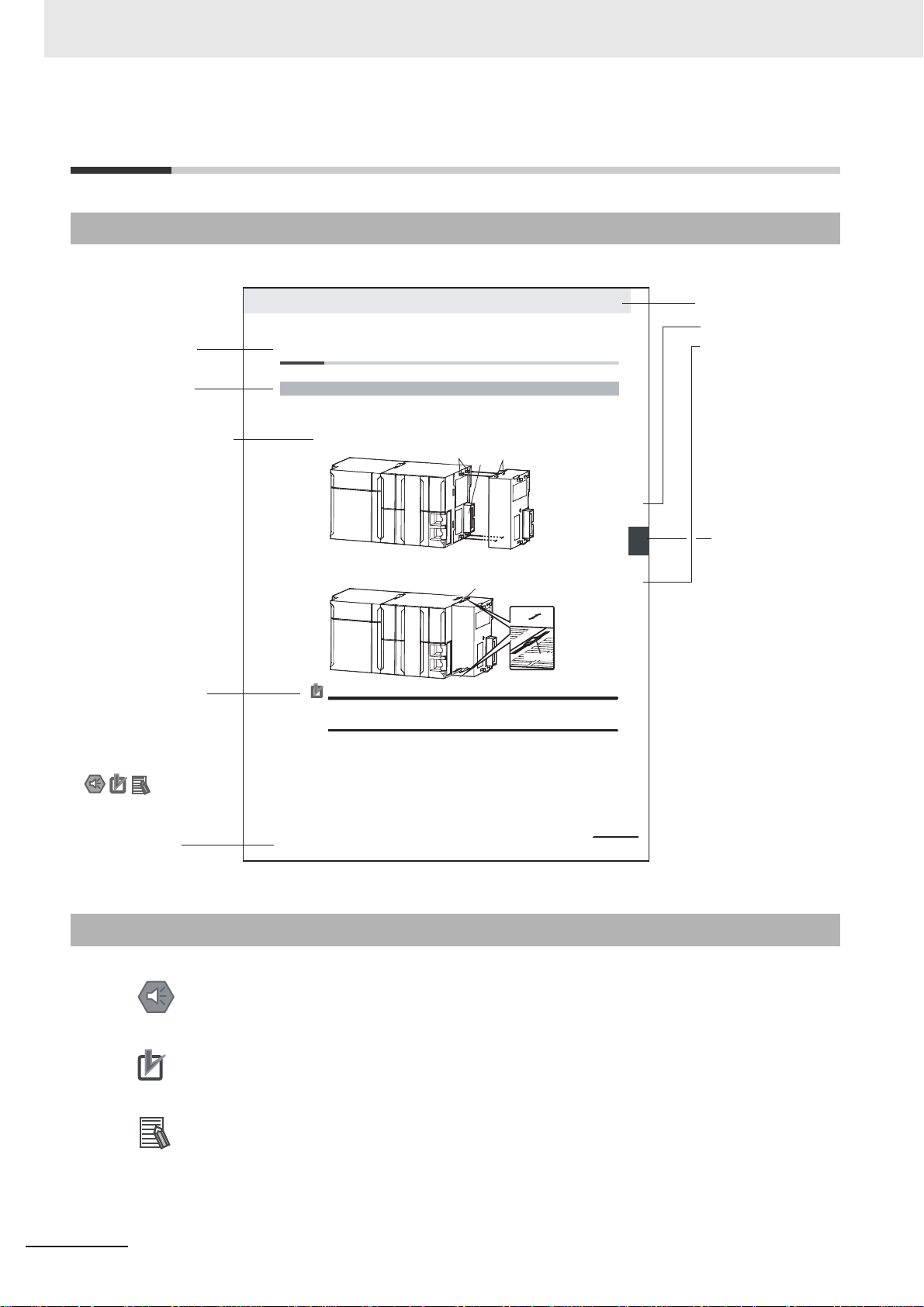
Manual Structure
4-9
4 Installation and Wiring
NJ-series CPU Unit Hardware User’s Manual (W500)
stinU gnitnuoM 3-4
4
stnenopmoC rellortnoC gnitcennoC 1-3-4
4-3 Mounting Units
The Units that make up an NJ-series Controller can be connected simply by pressing the Units together
and locking the sliders by moving them toward the back of the Units. The End Cover is connected in the
same way to the Unit on the far right side of the Controller.
1 Join the Units so that the connectors fit exactly.
2 The yellow sliders at the top and bottom of each Unit lock the Units together. Move the sliders
toward the back of the Units as shown below until they click into place.
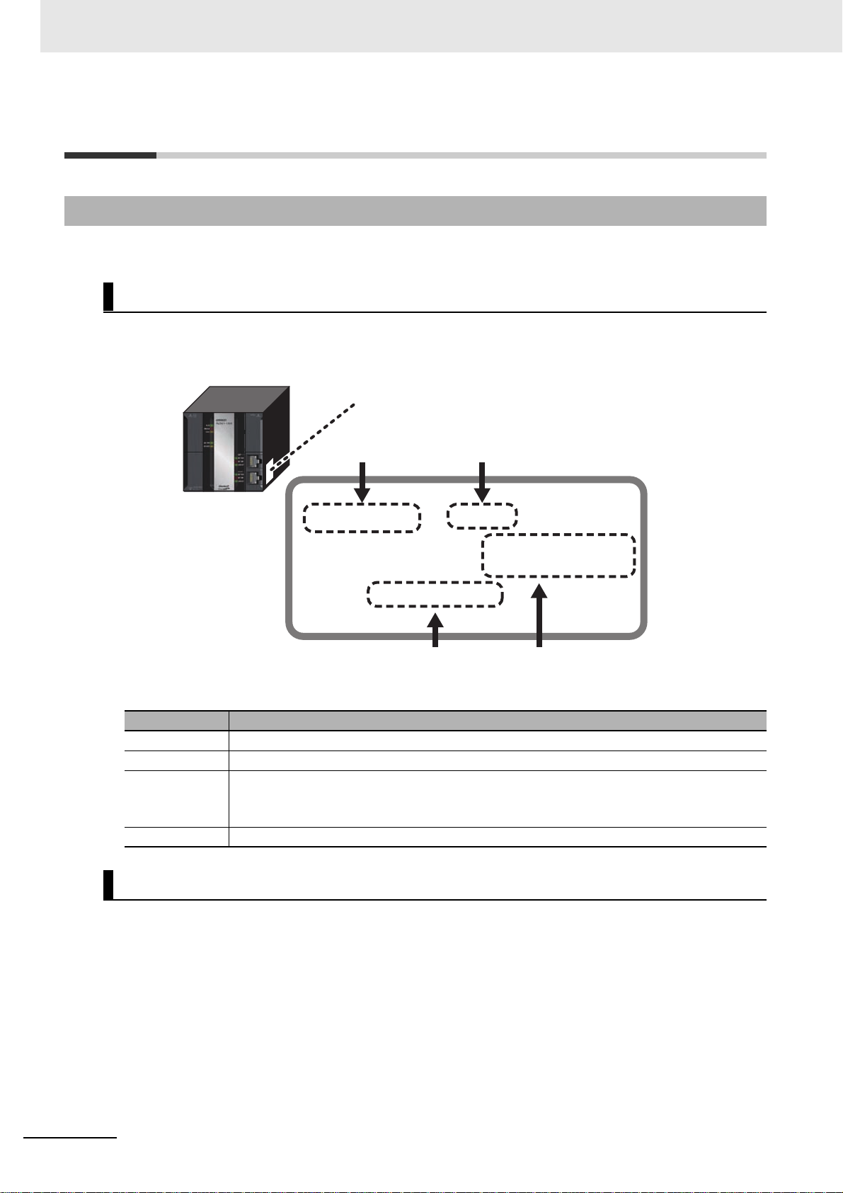
Precautions for Correct UsePrecautions for Correct Use
4-3-1 Connecting Controller Components
Connector
Hook
Hook holes
Slider
Lock
Release
Move the sliders toward the back
until they lock into place.
Level 1 heading
Level 2 heading
Level 3 heading
Level 2 heading
A step in a procedure
Manual name
Special information
Level 3 heading
Page tab
Gives the current
headings.
Indicates a procedure.
Icons indicate
precautions, additional
information, or reference
information.
Gives the number
of the main section.
This illustration is provided only as a sample. It may not literally appear in this manual.
The sliders on the tops and bottoms of the Power Supply Unit, CPU Unit, I/O Units, Special I/O
Units, and CPU Bus Units must be completely locked (until they click into place) after connecting
the adjacent Unit connectors.
Manual Structure
Page Structure
The following page structure is used in this manual.
Special Information
Special information in this manual is classified as follows:
Precautions for Safe Use
Precautions on what to do and what not to do to ensure safe usage of the product.
Precautions for Correct Use
Precautions on what to do and what not to do to ensure proper operation and performance.
Additional Information
Additional information to read as required.
This information is provided to increase understanding or make operation easier.
4
Note References are provided to more detailed or related information.
NJ-series Troubleshooting Manual (W503)
Page 7

Precaution on Terminology
In this manual, “download” refers to transferring data from the Sysmac Studio to the physical Controller
and “upload” refers to transferring data from the physical Controller to the Sysmac Studio.
For the Sysmac Studio, synchronization is used to both upload and download data. Here, “synchronize”
means to automatically compare the data for the Sysmac Studio on the computer with the data in the
physical Controller and tra nsfer the data in the direction that is specified by the user.
Manual Structure
NJ-series Troubleshooting Manual (W503)
5
Page 8

Manual Structure
6
NJ-series Troubleshooting Manual (W503)
Page 9
Sections in this Manual
1
2
3
1
2
3
I
Overview of Errors
Error Troubleshooting Methods
Error Tables
I
Index
Sections in this Manual
NJ-series Troubleshooting Manual (W503)
7
Page 10

Sections in this Manual
8
NJ-series Troubleshooting Manual (W503)
Page 11

CONTENTS
CONTENTS
Introduction............................................................................................................... 1
Relevant Manuals...................................................................................................... 2
Manual Structure ...................................................................................................... 4
Sections in this Manual............................................................................................ 7
Terms and Conditions Agreement........................................................................ 11
Safety Precautions ................................................................................................. 13
Precautions for Safe Use....................................................................................... 14
Precautions for Correct Use.................................................................................. 15
Regulations and Standards................................................................................... 16
Unit Versions........................................................................................................... 18
Related Manuals ..................................................................................................... 21
Revision History ..................................................................................................... 24
Section 1 Overview of Errors
1-1 Overview of NJ-series Errors .................................................................................................1-2
1-1-1 Types of Errors............................................................................................................................ 1-2
1-1-2 CPU Unit Status.......................................................................................................................... 1-3
1-2 Fatal Errors............................................................................................................................... 1-4
1-2-1 Types of Fatal Errors................................................................................................................... 1-4
1-2-2 Checking for Fatal Errors............................................................................................................ 1-4
1-3 Non-fatal Errors .............................................................. .... ... ... ... ............................................ 1-5
1-3-1 Types of Non-fatal Errors............................................................................................................1-5
1-3-2 Checking for Non-fatal Errors ...................................................................................................1-12
1-3-3 Resetting Non-fatal Errors........................................................................................................ 1-14
Section 2 Error Troubleshooting Methods
2-1 Troubleshooting Flowcharts................ .... ... ... ....................................... ..................................2-2
2-1-1 Checking to See If the CPU Unit Is Operating............................................................................ 2-2
2-1-2 Troubleshooting Flowchart for Non-fatal Errors.......................................................................... 2-3
2-2 Troubleshooting Fatal Errors......... ... ... .... ...................................... .... ..................................... 2-4
2-3 Troubleshooting Non-fatal Errors ........................................ ... ....................................... ........ 2-5
2-3-1 Identifying and Resetting Errors with the Sysmac Studio...........................................................2-5
2-3-2 Identifying and Resetting Errors with an NS-series PT .............................................................. 2-9
2-3-3 Identifying and Resetting Errors from the User Program..........................................................2-11
2-3-4 Checking for Errors with System-defined Variables.................................................................. 2-13
2-4 Troubleshooting When You Cannot Go Online from the Sysmac Studio......................... 2-14
2-4-1 Causes and Correction When You Cannot Go Online from the Sysmac Studio.......................2-14
2-4-2 Troubleshooting for Each Cause............................................................................................... 2-15
NJ-series Troubleshooting Manual (W503)
9
Page 12

CONTENTS
Section 3 Error Tables
3-1 Errors by Source...................................................................................................................... 3-2
3-1-1 Interpreting Error Descriptions....................................................................................................3-2
3-1-2 Errors in the PLC Function Module.............................................................................................3-2
3-1-3 Errors in the Motion Control Function Module...........................................................................3-46
3-1-4 Errors in the EtherNet/IP Function Module ...............................................................................3-74
3-1-5 Errors in the EtherCAT Master Function Module.......................................................................3-78
3-1-6 Errors in the DB Connection Service Function .........................................................................3-82
3-1-7 Errors in Slave Terminals..........................................................................................................3-87
3-1-8 Errors in EtherCAT Slaves.......................................................................................................3-108
3-1-9 Errors in CJ-series Units.........................................................................................................3-129
3-2 Events in Order of Event Codes.........................................................................................3-149
3-2-1 Interpreting Error Descriptions................................................................................................3-149
3-2-2 Error Table...............................................................................................................................3-150
3-3 Instruction Error Table ........................................................................................................ 3-182
Index
10
NJ-series Troubleshooting Manual (W503)
Page 13

Terms and Conditions Agreement
Terms and Conditions Agreement
Read and understand this Manual
Please read and understand this cat alog before pur chasin g the produ ct s. Please con sult your OMRON
representative if you have any questions or comments.
Warranty, Limitations of Liability
Warranties
Exclusive Warranty
Omron’s exclusive warranty is that the Products will be free from defects in materials and workmanship for a period of twelve months from the date of sale by Omron (or such other period expressed in
writing by Omron). Omron disclaims all other warranties, express or implied.
Limitations
OMRON MAKES NO WARRANTY OR REPRESENTATION, EXPRESS OR IMPLIED, ABOUT
NON-INFRINGEMENT, MERCHANTABILITY OR FITNESS FOR A PARTICULAR PURPOSE OF
THE PRODUCTS. BUYER ACKNOWLEDGES THAT IT ALONE HAS DETERMINED THAT THE
PRODUCTS WILL SUITABLY MEET THE REQUIREMENTS OF THEIR INTENDED USE.
Omron further disclaims all warranties and responsibility of any type for claims or expenses based
on infringement by the Products or otherwise of any intellectual prop erty right.
Buyer Remedy
Omron’s sole obligation hereunder sh all b e, at Omron ’s election, to (i) replace (in the form originally
shipped with Buyer responsible for labor charges for removal or replacement thereof) the non-complying Product, (ii) repair the non-complying Product, or (iii) repay or credit Buyer an amount equal
to the purchase price of the non-complying Product; provided that in no event shall Omron be
responsible for warranty, repair, indemnity or any other claims or expenses regarding the Products
unless Omron’s analysis confirms that the Products were properly handled, stored, installed and
maintained and not subject to contam ination, abuse, misuse or inappropriate modification. Retur n of
any Products by Buyer must be approved in writing by Omron before shipment. Omron Companies
shall not be liable for the suitability or unsuitability or the results from the use of Products in combination with any electrical or electronic components, circuits, system assemblies or any other materials or substances or environments. Any advice, recommendations or information given orally or in
writing, are not to be construed as an amendment or addition to the above warranty.
See http://www.omron.com/global/ or contact your Omron representative for published information.
Limitation on Liability; Etc
OMRON COMPANIES SHALL NOT BE LIABLE FOR SPECIAL, INDIRECT, INCIDENTAL, OR CONSEQUENTIAL DAMAGES, LOSS OF PROFITS OR PRODUCTION OR COMMERCIAL LOSS IN ANY
WAY CONNECTED WITH THE PRODUCTS, WHETHER SUCH CLAIM IS BASED IN CONTRACT,
WARRANTY, NEGLIGENCE OR STRICT LIABILITY.
Further, in no event shall liability of Omron Companies exceed the individual price of the Product on
which liability is asserted.
NJ-series Troubleshooting Manual (W503)
11
Page 14

Terms and Conditions Agreement
Application Considerations
Suitability of Use
Omron Companies shall not be responsible for conformity with any standards, codes or regulations
which apply to the combination of the Product in the Buyer’s application or use of the Product. At
Buyer’s request, Omron will provide applicable third party certification documents identifying ratings
and limitations of use which apply to the Product. This information by itself is not sufficient for a complete determination of the suitability of the Product in combination with the end product, machine, system, or other application or use. Buyer shall be solely responsible for determining appropriateness of
the particular Product with respect to Buyer’s application, product or system. Buyer shall take application responsibility in all cases.
NEVER USE THE PRODUCT FOR AN APPLICATION INVOLVING SERIOUS RISK TO LIFE OR
PROPERTY WITHOUT ENSURING THAT THE SYSTEM AS A WHOLE HAS BEEN DESIGNED TO
ADDRESS THE RISKS, AND THAT THE OMRON PRODUCT(S) IS PROPERLY RATED AND
INSTALLED FOR THE INTENDED USE WITHIN THE OVERALL EQUIPMENT OR SYSTEM.
Programmable Products
Omron Companies shall not be responsible for the user’s programming of a programmable Product, or
any consequence thereof.
Disclaimers
Performance Data
Data presented in Omron Company websites, catalogs and other materials is provided as a guide for
the user in determining suitability and does not constitute a warranty. It may represent the result of
Omron’s test conditions, and the user must correlate it to actual application req uirement s. Actual perfor mance is subject to the Omron’s Warranty and Limitations of Liability.
Change in Specifications
Product specifications and accessories may be changed at a ny time based on improvem ents and other
reasons. It is our practice to change part numbers when published ratings or features are changed, or
when significant construction changes are made. However, some specifications of the Product may be
changed without any notice. When in doubt, special part numbers may be assigned to fix or establish
key specifications for your application. Please consult with your Omron’s representative at any time to
confirm actual specifications of purchased Product.
12
Errors and Omissions
Information presented by Omron Companies has been checked and is believed to be accurate; however, no responsibility is assumed for clerical, typographical or proofreading errors or omissions.
NJ-series Troubleshooting Manual (W503)
Page 15

Safety Precautions
Refer to the following manuals for safety precaution s.
• NJ-series CPU Unit Hardware User’s Manu al (Cat No. W500)
• NJ-series CPU Unit Software User’s Manual (Cat No. W501)
Safety Precautions
NJ-series Troubleshooting Manual (W503)
13
Page 16

Precautions for Safe Use
Precautions for Saf e Use
Refer to the following manuals for precautions for the safe use of the NJ-series Controller.
Installation precautions are also provided for the NJ-series CPU Unit and the NJ-series Controller system.
• NJ-series CPU Unit Hardware User’s Manual (W500)
• NJ-series CPU Unit Software User’s Manual (W501)
14
NJ-series Troubleshooting Manual (W503)
Page 17

Precautions for Correct Use
Refer to the following manuals for pr ec au tio ns for the correct use of the NJ- se ries Controller.
Installation precautions are als o provided for the NJ-series CPU Unit and the NJ-series Controller sy stem.
• NJ-series CPU Unit Hardware User’s Manu al (W500)
• NJ-series CPU Unit Software User’s Manual (W501)
Precautions for Correct Use
NJ-series Troubleshooting Manual (W503)
15
Page 18

Regulations and Standards
Regulations and Standards
Conformance to EC Directives
Applicable Directives
• EMC Directives
• Low Voltage Directive
Concepts
EMC Directive
OMRON devices that comply with EC Directives also conform to the related EMC standards so that
they can be more easily built into other devices or the overall machine. The actual products have
been checked for conformity to EMC standards.*
Whether the products conform to the standards in the system used by the customer, however, must
be checked by the customer. EMC-related performance of the OMRON devices that com ply with EC
Directives will vary depending on the configuration, wiring, and other conditions of the equipment or
control panel on which the OMRON de vices are installed. The customer must, ther ef ore , perf orm the
final check to confirm that devices and the overall machine conform to EMC standards.
* Applicable EMC (Electromagnetic Compatibility) standards are as follows:
EMS (Electromagnetic Susceptibility): EN 61131-2 and EN 61000-6-2
EMI (Electromagnetic Interference): EN 61131-2 and EN 61000-6-4 (Radiated emission: 10-m regulations)
Low Voltage Directive
Always ensure that devices operating at voltages of 50 to 1,000 VAC and 75 to 1,500 VDC meet the
required safety standards. The applicable directive is EN 61131-2.
Conformance to EC Directives
The NJ-series Controllers comply with EC Directives. To ensure that the machine or device in which
the NJ-series Controller is used complies with EC Directives, the Controller must be installed as follows:
• The NJ-series Controller must be installed within a cont rol panel.
• You must use reinforced insulation or double insulation for the DC power supplies connected to
DC Power Supply Units and I/O Units.
• NJ-series Controllers that comply with EC Directiv es al so conform to the Common Emission Standard (EN 61000-6-4). Radiated emission characteristics (10-m regulations) may var y depending
on the configuration of the control panel used, other devices connected to the control panel, wiring, and other conditions.
You must therefore confirm that the overall machine or equipment complies with EC Directives.
16
NJ-series Troubleshooting Manual (W503)
Page 19
Conformance to KC Standards
Observe the following precaution if you use NX-series Units in Korea.
Class A Device (Broadcasting Communications Device for Office Use)
This device obtained EMC registration for office use (Class A), and it is intended to be used in places
other than homes.
Sellers and/or users need to take note of this.
Conformance to Shipbuilding Standards
Regulations and Standards
The NJ-series Controllers comply with the following shipbuilding standards. Applicability to the shipbuilding standards is based on certain usage conditions . I t may not be possible to use the product in
some locations. Contact your OMRON representative before attempting to use a Contro ller on a
ship.
Usage Conditions for NK and LR Shipbuilding Standards
• The NJ-series Controller must be installed within a control panel.
• Gaps in the door to the control panel must be completely filled or covered with gaskets or other
material.
• The following noise filter must be connected to the power supply line.
Noise Filter
Manufacturer Model
Cosel Co., Ltd. TAH-06-683
Software Licenses and Copyrights
This product incorporates certain third party software. The license and copyright information associated with this software is available at http://www.fa.omron.co.jp/nj_info_e/.
NJ-series Troubleshooting Manual (W503)
17
Page 20
Unit Versions
Unit Versions
Unit Versions
A “unit version” has been introduced to manage CPU Units in the NJ Series according to differences in
functionality accompanying Unit upgrades.
Notation of Unit Versions on Products
The unit version is given on the ID information label of the products for which unit versions are managed, as shown below.
Example for NJ-series NJ501-@@@@ CPU Unit:
ID information label
Unit model
NJ501 -1500 Ver.1.@@
PORT1 MAC ADDRESS: @@@@@@@@@@@@
PORT2 MAC ADDRESS: @@@@@@@@@@@@
Lot No. DDMYY@ xxxx
Unit version
Lot number and serial number MAC address
The following information is provided on the ID information label.
Item Description
Unit model Gives the model of the Unit.
Unit version Gives the unit version of the Unit.
Lot number and
serial number
MAC address Gives the MAC address of the built-in port on the Unit.
Gives the lot number and serial number of the Unit.
DDMYY: Lot number, @: For use by OMRON, xxxx: Serial number
“M” gives the month (1 to 9: January to September, X: October, Y: November, Z: December)
18
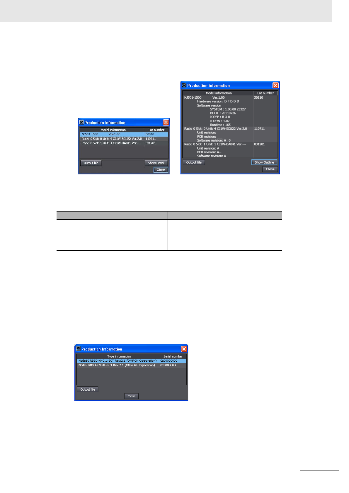
Confirming Unit Versions with Sysmac Studio
You can use the Unit Production Information on the Sysmac Studio to check the unit version of the CPU
Unit, CJ-series Special I/O Units, CJ-series CPU Bus Units, and EtherCAT slaves. The unit ve rsions of
CJ-series Basic I/O Units cannot be checked from the Sysmac Studio.
CPU Unit and CJ-series Units
1 Double-click CPU/Expansion Racks under Configurations and Setup in the Multiview
Explorer. Or, right-click CPU/Expansion Racks under Configurations and Setup and select
Edit from the menu.
The Unit Editor is displayed for the Controller Configurations and Setup layer.
NJ-series Troubleshooting Manual (W503)
Page 21
Unit Versions
2 Right-click any open space in the Unit Editor and select Production Information.
The Production Information Dialog Box is displayed.
Simple Display Detailed Display
In this example, “Ver.1.00” is displayed next to the unit model.
The following items are displayed.
CPU Unit CJ-series Units
Unit model
Unit version
Lot number
Unit model
Unit version
Lot number
Rack number, slot number, and unit number
EtherCAT Slaves
1 Double-click EtherCAT under Configurations and Setup in the Multiview Explorer. Or, right-
click EtherCAT under Configurations and Setup and select Edit from the menu.
The EtherCAT Configuration Tab Page is displayed for the Controller Configurations and Setup
layer.
2 Right-click the master in the EtherCAT Configurations Editing Pane and select Display Produc-
tion Information.
The Production Information Dialog Box is displayed.
The following items are displayed.
Node address
Type information*
Serial number
* If the model number cannot be determined (such as when there is no ESI file), the vendor ID, product
code, and revision number are displayed.
NJ-series Troubleshooting Manual (W503)
19
Page 22

Unit Versions
Additional Information
Refer to the manual for the specific Unit for the unit versions of the CPU Units, Communications
Coupler Units, NX Units, and Safety Control Units to which the database connection service and
other functions were added.
Unit Versions and Sysmac Studio Versions
The events that can occur depend on the unit versions of the NJ-series CPU Unit and the EtherCAT
slaves . You must use the corresponding v ersion of Sysm ac Studio to display events that were added for
version upgrades when troubleshooting from the Sysmac Studio or from the Troubleshooter on an NSseries PT. Refer to the product manuals for information on the unit versions of the CPU Unit and EtherCAT slaves, and for the relationship with the version of the Sysmac Studio.
Unit Version Notation
In this manual, unit versions are specified as shown in the following table.
Product nameplate Notation in this manual Remarks
“Ver.1.0” or later to the right of
the lot number
Unit version 1.0 or later Unless unit versions are specified, the information in this manual
applies to all unit versions.
20
NJ-series Troubleshooting Manual (W503)
Page 23

Related Manuals
The following manuals are related to the NJ-series Controllers. Use these manuals for reference.
Manual name Cat. No. Model numbers Application Description
NJ-series CPU Unit
Hardware User’s Manual
NJ-series CPU Unit Software User’s Manual
NJ-series CPU Unit
Motion Control User’s
Manual
NJ-series Instructions
Reference Manual
NJ-series Motion Control
Instructions Reference
Manual
NJ-series CPU Unit Builtin EtherCA T® P ort User’s
Manual
NJ-series CPU Unit Builtin EtherNet/IP
User’s Manual
TM
Port
W500 NJ501-@@@@
NJ301-@@@@
W501 NJ501-@@@@
NJ301-@@@@
W507 NJ501-@@@@
NJ301-@@@@
W502 NJ501-@@@@
NJ301-@@@@
W508 NJ501-@@@@
NJ301-@@@@
W505 NJ501-@@@@
NJ301-@@@@
W506 NJ501-@@@@
NJ301-@@@@
Learning the basic
specifications of the NJseries CPU Units,
including introductory
information, designing,
installation, and maintenance. Mainly hardware
information is provided.
Learning how to program and set up an NJseries CPU Unit. Mainly
software information is
provided.
Learning about motion
control settings and programming concepts.
Learning detailed specifications on the basic
instructions of an NJseries CPU Unit.
Learning about the
specifications of the
motion control instructions that are provided
by OMRON.
Using the built-in EtherCAT port on an NJseries CPU Unit.
Using the built-in EtherNet/IP port on an NJseries CPU Unit.
An introduction to the entire NJ-series system is
provided along with the following information on the
CPU Unit.
• Features and system configuration
• Introduction
• Part names and functions
• General specifications
• Installation and wiring
• Maintenance and inspection
Use this manual together with the NJ-series CPU
Unit Software User’s Manual (Cat. No. W501).
The following information is provided on a Control-
ler built with an NJ501 CPU Unit.
• CPU Unit operation
• CPU Unit features
• Initial settings
• Programming based on IEC 61131-3 language
specifications
Use this manual together with the NJ-series CPU
Unit Hardware User’s Manual (Cat. No. W500).
The settings and operation of the CPU Unit and
programming concepts for motion control are
described. Use this manual together with the NJ-
series CPU Unit Hardware User’s Manual (Cat. No .
W500) and NJ-series CPU Unit Software User’s
Manual (Cat. No. W501).
The instructions in the instruction set (IEC 61131-3
specifications) are described. When programming,
use this manual together with the NJ-series CPU
Unit Hardware User’s Manual (Cat. No. W500) and
NJ-series CPU Unit Software User’s Manual (Cat.
No. W501).
The motion control instructions are described.
When programming, use this manual together with
the NJ-series CPU Unit Hardware User’s Manual
(Cat. No. W500), NJ-series CPU Unit Software
User’s Manual (Cat. No
Unit Motion Control User’s Manual (Cat. No.
W507).
Information on the built-in EtherCAT port is pro-
vided. This manual provides an introduction and
provides information on the configuration, features,
and setup.
Use this manual together with the NJ-series CPU
Unit Hardware User’s Manual (Cat. No. W500) and
NJ-series CPU Unit Software User’s Manual (Cat.
No. W501).
Information on the built-in EtherNet/IP port is pro-
vided. Information is provided on the basic setup,
tag data links, and other features.
Use this manual together with the NJ-series CPU
Unit Hardware User’s Manual (Cat. No. W500) and
NJ-series CPU Unit Software User’s Manual (Cat.
No. W501).
Related Manuals
. W501) and NJ-ser
ies CPU
NJ-series Troubleshooting Manual (W503)
21
Page 24

Related Manuals
Manual name Cat. No. Model numbers Application Description
NJ-series Troubleshooting Manual
NJ-series Database Connection CPU Units User’s
Manual
NX-series Communications Coupler Unit User’s
Manual
NX-series NX Units
User’s Manuals
NX-series Safety Control
Unit User’s Manual
NX-series Safety Control
Unit Instructions Reference Manual
CJ-series Special Unit
Manuals for NJ-series
CPU Unit
Sysmac Studio V ersion 1
Operation Manual
CX-Integrator
CS/CJ/CP/NSJ/NJ-series
Network Configuration
Tool Operation Manual
CX-Designer User’s
Manual
W503 NJ501-@@@@
NJ301-@@@@
W527 NJ501-1@20 Using the database con-
W519 NX-ECC@@@ Leaning how to use an
W521
W522
W523
W524
W525
Z930 NX-SL@@@@
Z931 NX-SL@@@@ Learning about the
W490
W498
W491
Z317
W492
W494
W497
W495
W493
W504 SYSMAC-
W464 Learning how to config-
V099 Learning to create
NX-ID@@@@
NX-OC@@@@
NX-OD@@@@
NX-AD@@@@
NX-DA@@@@
NX-TS@@@@
NX-PD1@@@
NX-PF0@@@
NX-TBX@@
NX-EC0@@@
NX-ECS@@@
NX-PG0@@@
NX-
@@@@@@
NX-SI@@@@
NX-SO
@@@@
CJ1W-@@@@ Learning how to use CJ-
SE2@@@
Learning about the
errors that may be
detected in an NJ-series
Controller.
nection service with NJseries Controllers
NX-series Communications Coupler Unit and
Slave Terminals
Learning how to use NX
Units
Learning how to use
NX-series Safety Control Units
specifications of instructions for the Safety CPU
Unit.
series Units with an NJseries CPU Unit.
Learning about the
operating procedures
and functions of the
Sysmac Studio.
ure networks (data links,
routing tables, Communications Unit settings,
etc.).
screen data for NSseries Programmable
Terminals.
Concepts on managing errors that may be detected
in an NJ-series Controller and information on individual errors are described.
Use this manual together with the NJ-series CPU
Unit Hardware User’s Manual (Cat. No. W500) and
NJ-series CPU Unit Software User’s Manual (Cat.
No. W501).
Describes the database connection service.
Introduces the system, configuration methods, Unit
hardware, setting methods, and functions of Slave
Terminals that consist of a Communications Coupler Unit and NX Units. A manual is available f or the
following Unit.
EtherCAT Coupler Unit
Describe the hardware, setup methods, and functions of the NX Units.
Manuals are available for the following Units.
Digital I/O Units, Analog I/O Units, System Units,
and Position Interface Units
Describes the hardware, setup methods, and functions of the NX-series Safety Control Units.
Describes the instructions for the Safety CPU Unit.
When programming, use this manual together with
the NX-series Safety Control Unit User’s Manual
(Cat. No. Z930).
The methods and precautions for using CJ-series
Units with an NJ501 CPU Unit are described,
including access methods and programming interfaces. Manuals are available for the following Units.
Analog I/O Units, Insulated-type Analog I/O Units,
Temperature Control Units, ID Sensor Units, Highspeed Counter Units, Serial Communications Units,
DeviceNet Units, EtherNet/IP Units, and CompoNet
Master Units.
Use these manuals together with the NJ-series
CPU Unit Hardware User’s Manual (Cat. No . W500)
and NJ-series CPU Unit Software User’s Manual
(Cat. No. W501).
Describes the operating procedures of the Sysmac
Studio.
Describes operating procedures for the CX-Integrator.
Describes operating procedures for the CXDesigner.
22
NJ-series Troubleshooting Manual (W503)
Page 25

Manual name Cat. No. Model numbers Application Description
CX-Protocol Operation
Manual
GX-series EtherCAT
Slave Unit User’s Manual
MX2/RX Series Inverter
EtherCAT Communication Unit User’s Manual
G5-series AC Servomotors/Servo Drives with
Built-in EtherCAT Communications User’s Manual
G5-series Linear
Motors/Drives with Builtin EtherCAT Communications Linear Motor Type
User’s Manual
FH/FZ5 Vision System
FH/FZ5 Series User’s
Manual for Communications Settings
FQ-M-series Specialized
Vision Sensor for Positioning User’s Manual
EtherCAT Digital-type
Sensor Communication
Unit Operation Manual
E3NW-ECT EtherCAT
Digital Sensor Communications Unit Operation
Manual
ZW-CE1@T Confocal
Fiber Type Displacement
Sensor User’s Manual
W344 Creating data transfer
protocols for generalpurpose devices connected to CJ-series
Serial Communications
Units.
W488 GX-ID@@@@
GX-OD@@@@
GX-OC@@@@
GX-MD@@@@
GX-AD@@@@
GX-DA@@@@
GX-EC@@@@
XWT-ID@@
XWT-OD@@
I574 3G3AX-MX2-ECT
3G3AX-RX-ECT
I576 R88D-KN@-ECT
R88M-K@
I577 R88D-KN@-ECT-L
R88L-EC-@W-@
R88L-EC-@M-@
Z342 FH-3@@@@
FH-1@@@@
Z314 FQ-MS12@ Leaning how to connect
E413 E3X-ECT Leaning how to connect
E429 E3NW-ECT Leaning how to connect
Z332 ZW-CE1@T Leaning how to connect
Leaning how to connect
GX-series EtherCAT
Slave Units.
Leaning how to connect
a 3G3AX-MX2-ECT or
3G3AX-RX-ECT EtherCAT Communications
Unit for MX2/RX-series
Inverters.
Leaning how to connect
G5-series AC Servomotors/Servo Drives with
Built-in EtherCAT Communications.
Leaning how to connect
G5-series Linear
Motors/Drives with Builtin EtherCAT Communications Linear Motor
Type.
Leaning how to connect
FH/FZ5-series Vision
Systems
FQ-M-series Specialized Vision Sensor for
Positioning.
E3X-series EtherCAT
Slave Units.
E3NW EtherCAT Slave
Units.
ZW-CE1@T EtherCAT
Slave Units.
Describes operating procedures for the CX-Protocol.
Provides the specifications of and describes application methods for GX-series EtherCAT Slave
Units.
Describes the following information for the 3G3AXMX2-ECT and 3G3AX-RX-ECT EtherCAT Communications Unit for MX2/RX-series Inverters: installation, parameter settings required for operation,
troubleshooting, and inspection methods.
Describes the following information for the G5series AC Servomotors/Servo Drives with EtherCAT Communications: installation, wiring methods,
parameter settings required for operation, troubleshooting, and inspection methods.
Describes the following information for the G5series Linear Motors/Drives with EtherCAT Communications Linear Motor Type: installation, wiring
methods, parameter settings required for operation,
troubleshooting, and inspection methods.
The functions, settings, and communications methods to communicate with FH/FZ5-series Vision
Systems fro
described.
Describes the following information for the FQ-Mseries Specialized Vision Sensor for Positioning:
installation, wiring methods, parameter settings
required for operation, troubleshooting, and inspection methods.
Provides the specifications of and describes application methods for E3X-series EtherCAT Slave
Units.
Provides the specifications of and describes application methods for E3NW EtherCAT Slave Units
are provided.
Provides the specifications of and describes application methods for ZW-CE1@T EtherCAT Slave
Units are provided.
m a PLC or other ex
Related Manuals
ternal device are
NJ-series Troubleshooting Manual (W503)
23
Page 26
Revision History
W503-E1-08
Revision code
Cat. No.
Revision History
A manual revision code appears as a suffix to the catalog number on the front and back covers of the
manual.
Revision code Date Revised content
01 July 2011 Original production
02 March 2012 Added information related to the upgrade to unit version 1.01,
03 May 20 12 Added information related to the upgrade to unit version 1.02,
04 August 2012 Made additions to events and changes to the contents related
05 February 2013 Made additions to events and changes to the contents related
06 April 2013 Made additions to ev ents and changes to the contents related
07 J une 2013 Made additions to events and changes to the contents related
08 September 2013 Made additions to events and changes to the contents related
made additions and changes to events related to the addition
of devices that can be connected, and corrected mistakes.
made additions and changes to events related to the addition
of devices that can be connected, and corrected mistakes.
to the upgrade to unit version 1.03, and corrected mistakes.
to the upgrade to unit version 1.04, and corrected mistakes.
to the upgrade to unit version 1.05, and corrected mistakes.
to the upgrade to unit version 1.06, and corrected mistakes.
to the upgrade to unit version 1.07, and corrected mistakes.
24
NJ-series Troubleshooting Manual (W503)
Page 27

Overview of Errors
This section provides information that is required to troubleshoot errors. It introduces
the types of errors that can occur on an NJ-series Controller, the operation that occurs
in response to errors, and the methods you can use to check for errors. Refer to Sec-
tion 2 Error Troubleshooting Methods for information on troubleshooting errors.
1-1 Overview of NJ-series Errors . . . . . . . . . . . . . . . . . . . . . . . . . . . . . . . . . . . . 1-2
1-1-1 Types of Errors . . . . . . . . . . . . . . . . . . . . . . . . . . . . . . . . . . . . . . . . . . . . . . . . . 1-2
1-1-2 CPU Unit Status . . . . . . . . . . . . . . . . . . . . . . . . . . . . . . . . . . . . . . . . . . . . . . . . 1-3
1-2 Fatal Errors . . . . . . . . . . . . . . . . . . . . . . . . . . . . . . . . . . . . . . . . . . . . . . . . . . . 1-4
1-2-1 Types of Fatal Errors . . . . . . . . . . . . . . . . . . . . . . . . . . . . . . . . . . . . . . . . . . . . 1-4
1-2-2 Checking for Fatal Errors . . . . . . . . . . . . . . . . . . . . . . . . . . . . . . . . . . . . . . . . . 1-4
1-3 Non-fatal Errors . . . . . . . . . . . . . . . . . . . . . . . . . . . . . . . . . . . . . . . . . . . . . . . 1-5
1-3-1 Types of Non-fatal Errors . . . . . . . . . . . . . . . . . . . . . . . . . . . . . . . . . . . . . . . . . 1-5
1-3-2 Checking for Non-fatal Errors . . . . . . . . . . . . . . . . . . . . . . . . . . . . . . . . . . . . 1-12
1-3-3 Resetting Non-fatal Errors . . . . . . . . . . . . . . . . . . . . . . . . . . . . . . . . . . . . . . . 1-14
1
NJ-series Troubleshooting Manual (W503)
1-1
Page 28
1 Overview of Errors
NS-series PT
Host computer
Built-in EtherCAT port
Built-in EtherNet/IP
port
Troubleshooting functions
Troubleshooter
EtherNet/IP
EtherCAT
Sysmac Studio
CJ-series Units
NJ-series
CPU Unit
Error management range for
NJ-series Controller
EtherCAT
slaves
1-1 Overview of NJ-series Errors
You manage all of the errors that occur on the NJ-series Controller as events. The same methods are
used for all events. This allows you to see what errors have occurred and find corrections for them with
the same methods for t he entire ran ge of er rors that is ma naged (i.e ., CPU Unit, NX-series Sla ve T erminals, EtherCAT slaves,* and CJ-series Units).
* Only Sysmac devices are supported. For information on EtherCAT slaves that are Sysmac devices, refer to the
NJ-series CPU Unit Built-in EtherCAT Port User’s Manual (Cat. No. W505).
1-1-1 Types of Errors
1-2
You can use the troubleshooting functions of the Sysmac Studio or the Troubleshooter on an NS-series
PT to quickly check for errors that have occurred and find corrections for them.
To perform troubleshooting from an NS-series PT, connect the PT to the built-in EtherNet/IP port on the
CPU Unit.
There are two main types of errors (events) depending on whether the NJ-series Con troller can manage them or not.
Fatal Errors
These errors are not detected by the event management function of the NJ-series Controller
because the CPU Unit stops operation. You cannot identify or reset these errors with the Sysmac
Studio or an NS-series PT.
Refer to 1-2 Fatal Errors for error types and confirmation methods for fatal errors.
NJ-series Troubleshooting Manual (W503)
Page 29
Non-fatal Errors
PWR indicator
RUN indicator
ERROR indicator
Power Supply Unit CPU Unit
These errors are detected and managed with the event management function of the NJ-series Controller. You can confirm these errors with the Sysmac Studio or an NS-series PT.
Refer to 1-3 Non-fatal Errors for error types and confirmation methods for non-fatal errors.
1-1-2 CPU Unit Status
1 Overview of Errors
1-1 Overview of NJ-series Errors
You can check the operating status of the CPU Unit with the PWR, RUN, and ERROR indicators on the
front panels of the Power Supply Unit and CPU Unit.
The following table shows the status of the front-panel indicators, the status of user program execution,
and the ability to make a software connection to the Sysmac Studio or an NS-series PT during startup,
during normal operation, and when there are errors in the Controller.
Power
Supply
CPU Unit operating status
During startup
During normal
operation
Fatal errors
Non-fatal errors
*1 Refer to 1-2 Fatal Errors for information on individual errors.
*2 Refer to 1-3 Non-fatal Errors for information on individual errors.
*3 The function module where the error occurred stops.
RUN mode Lit Lit Not lit Continues. Possible.
PROGRAM mode Lit Not lit Not lit Stops.
Power Supply Error
CPU Unit Reset
Incorrect Power Supply Unit Connected
CPU Unit Watchdog
Timer Error
Major fault
Partial fault
Minor fault
Observation
*1
*2
*2
*2
*2
*1
*1
*1
Unit
PWR
(green)
Lit Flashing
Not lit Not lit Not lit Stops. Not possible.
Lit Not lit Not lit Stops.
Lit Flashing
Lit Not lit Lit Stops.
Lit Not lit Lit Stops. Possible. (CommuniLit Lit Flashing
Lit Lit Flashing
Lit Lit Not lit Continues.
RUN
(green)
(1-s inter-
vals).
(3-s inter-
vals).
CPU Unit
ERROR
(1-s inter-
(1-s inter-
User pro-
gram execu-
tion status
(red)
Not lit Stop s. Not possible.
Lit Stops.
Continues.
vals).
Continues.
vals).
Software connection to Sysmac Studio or NS-series PT
cations can be con-
*3
nected from an NS-
series PT if Ether-
Net/IP is operating
normally.)
1
1-1-2 CPU Unit Status
NJ-series Troubleshooting Manual (W503)
1-3
Page 30

1 Overview of Errors
1-2 Fatal Errors
1-2-1 Types of Fatal Errors
This section describes the errors that cause the operation of the NJ-series CPU Unit to stop.
Software connections to the Sysmac Studio or an NS-series PT cannot be made if there is a fatal error
in the Controller.
Power Supply Error
Po wer is not supplied, the voltage is outside of the allowed range, or the Power Supply Unit is faulty.
CPU Unit Reset
The CPU Unit stopped operation because of a hardware error. Other than hardware failures, this
error also occurs at the following times.
• The power supply to an Expansion Rac k is OFF.
• The I/O Connecting Cable is incorrectly installed.
• The IN and OUT connectors are reversed.
• The connectors are not mated properly.
• There is more than one I/O Control Unit on the CPU Rack or there is an I/O Control Unit on an
Expansion Rack.
Incorrect Power Supply Unit Connected
There is a CJ-series Power Supply Unit connected to the CPU Rack. The operation of the Con trolle r
is stopped.
CPU Unit W atchdog Timer Error
This error occurs in the CPU Unit. This error occurs when the watchdog timer times out because a
hardware failure or when temporary data corruption causes the CPU Unit to hang.
1-2-2 Checking for Fatal Errors
You can identify fat al err or s ba sed o n t he sta tus of t he PWR in dicator on t he Power Supply Unit and the
RUN and ERROR indicators on the CPU Unit, as we ll as by the ability to go online with the CPU Unit
from the Sysmac Studio. Refer to Section 2 Error Troubleshooting Methods for information on identify-
ing errors and corrections.
Indicators
PWR (green) RUN (green) ERROR (red)
Not lit Not lit Not lit Not possible.* Power Supply Error
Lit Not lit Not lit CPU Unit Reset
Lit Flashing (3-s
intervals).
Lit Not lit Lit CPU Unit Watchdog Timer
* Power Supply Errors and Incorrect Power Supply Unit Connected errors can be differentiated with the indicators.
There is no need to see if you can go online with the CPU Unit from the Sysmac Studio.
Going online from
the Sysmac Studio
Lit Incorrect Power Supply Unit
CPU Unit operating status
Connected
Error
1-4
NJ-series Troubleshooting Manual (W503)
Page 31

1-3 Non-fatal Errors
Non-fatal errors that occur are managed as events in the NJ-series Controller. You can check the event
to find out what type of error occurred.
1 Overview of Errors
1-3 Non-fatal Errors
1-3-1 Types of Non-fatal Errors
Overview of Controller Events (Errors and Information)
You use the same methods to manage all of the events that occur on the NJ-series Controller. The
events that occur are saved in battery-backup memory in the CPU Unit and NX-series Slave Terminals.
You can use the Sysmac Studio or an NS-ser ies PT to confir m current Co ntroller events and the log of
events that occurred before. This log is called an event log.
To use an NS-series PT to check events, connect the PT to the built-in EtherNet/IP port on the CPU
Unit.
Check current Controller
events and the event log
of past events.
Sysmac Studio
NS-series PT
Event source
Or
PLC Function
Module
NJ-series CPU Unit
Motion Control
Function Module
Event logs
EtherCAT Master
Function Module
EtherNet/IP
Function Module
User program
Create User-defined
Error instruction:
Create User-defined
instruction: SetInfo
SetAlarm
Information
CJ-series
Units
Errors in
Special Units
1
1-3-1 Types of Non-fatal Errors
Check current Controller
events and the event log
of past events.
Backup battery
EtherCAT
Slave
Terminal
EtherCAT
slave
Note Refer to the manual for the Communications Coupler Unit for details on the event log in a Slave Terminal.
The following events can occur.
Controller Events
The Controller automatically detects thes e events. Controller events include events for the function
modules in the CPU Unit, NX-series Slave Terminal, EtherCAT slaves, and CJ-series Units.
The error logs from within the EtherCAT slaves and the CJ-series Special Units are not included.
Refer to the manuals for the slaves or Special Units for the procedures to read their error logs. You
can check the error logs from CJ-series Special Units on the Controller Event Log Tab Page of the
Sysmac Studio.
User-defined Events
These are events that occur in applications that the user developed.
Refer to the NJ-series CPU Unit Software User’s Manual (Cat. No. W501) for information on user-
defined events.
Non-fatal errors are managed as Controlle r events. This section describes mainly the Controller events.
NJ-series Troubleshooting Manual (W503)
1-5
Page 32

1 Overview of Errors
Details on Controller Events (Errors and Information)
Sources of Controller Events
The Event source information indicates the location where an event occurred. The event source
identifies the particular function module in the CPU Unit in which the ev ent occurred . F or some function modules, there is more detailed information about the event source. This information is called
the Source details. The following information is provided as the event source details.
Event source Source details
PLC Function Module Instructions, I/O bus master, or CJ-series Unit
Motion Control Function Module Common, axis, or axes group
EtherCAT Master Function Module Communications port, EtherCAT master, EtherCAT Coupler
EtherNet/IP Function Module Communications por t , C I P, F T P, N T P, o r S N M P
The event source is displayed on the Sysmac Studio or NS-series PT.
Levels of Controller Events (Errors and Information)
Unit, NX Unit, or EtherCAT slave
The following table classifies the levels of Controller events according to the effect that the errors
have on control.
No. Level Classification Level name
1 High Controller errors Major fault lev el
2 Partial fault level
3Minor fault level
4 Observation
5 Low Controller informa-
tion
Information
Errors with a higher level have a greater impact on the fu nctions that the NJ-series Controller provides, and are more difficult to recover from. When an event occurs, the Sysmac Studio or PT will
display the level.
Event Levels
• Major Fault Level
These errors prevent control operations for the entire Controller. When the CPU Unit detects a
major fault, it immediately stops the execution of the user program and turns OFF the load s of all
slave, including remote I/O. With EtherCAT slaves and some CJ-series Special Units, you can set
the slave settings or Unit settings to select whether outputs will go OFF or retain their previous
status. You cannot reset major fault level errors from the user program, the Sysmac Studio or an
NS-series PT. To recover from a major fault level error, remove the cause of the error, and either
cycle the power supply to the Controller, or reset the Controller from the Sysmac Studio.
• Partial Fault Level
These errors prevent control operations in a certain function module in the Controller. The NJseries CPU Unit continues to execute the user program even after a partial fa ult level error occurs.
You can include error processing in the user program in order to stop eq uipment safely. After you
remove the cause of the error, execute one of the following to return to normal status.
• Reset the error from the user program, the Sysmac Studio, or an NS-series PT.
• Cycle the power supply.
• Reset the Controller from the Sysmac Studio.
• Minor Fault Level
These errors prevent par t of the control operations in a certain function module in the Controller.
The troubleshooting for minor fault level errors is the same as the processing for partial fault level
errors.
1-6
NJ-series Troubleshooting Manual (W503)
Page 33

1 Overview of Errors
• Observations
These errors do not affect the control operations of the Controller. The observation notifies you of
potential problems before they deve lo p into a minor fault level error or worse.
• Information
Events that are classified as information provide information that do not indicate errors.
You can change the event level for some events. Refer to the NJ-series CPU Unit Software User’s Man-
ual (Cat. No. W501) for details on changing event le vels. Refer to 3-1 Errors by Source in this man ual to
see the events for which you can change the event level.
Operation for Each Level
The way that the Controller operates when an event occurs depends on the level of the Controller
event.
Event level
Item
Definition
Event examples
(Only a few e x a mples are provided
here. Refer to Sec-
tion 3 Error Tables
for a list of all of
the errors.
PWR
*1
(green)
RUN
(green)
ERROR
(red)
Frontpanel
indica-
tors
Controller errors
Major fault
level
These errors
are serious
errors that prevent control
operations for
the entire Controller.
• I/O Bus
Check Error
(PLC Function Module)
Lit Lit Lit Lit Lit
Not lit Lit Lit Lit Lit
Lit Flashes at 1-s
Partial fault
level
These errors
prevent all of
the control in a
function module other than
PLC Function
Module.
• Motion Control Period
Exceeded
(Motion Control Function
Module)
• Communications Controller Failure
(EtherCAT
Master Function Module)
intervals.
Minor fault
level
These errors
preven t pa rt of
the control
operations in a
certain function module.
• Positive Limit
Input
Detected
(Motion Control Function
Module)
• Analog Input
Disconnection Detected
(CJ-series
Unit)
• Low Battery
V oltage (PLC
Function
Module)
Flashes at 1-s
intervals.
Observation Information
These errors
do not affect
system control
operations.
• Packet Discarded Due
to Full
Reception
Buffer (EtherNet/IP
Function
Module)
Not lit Not lit
Controller
information
These are not
errors, but
appear in the
event log to
notify the user
of specific
information.
• Power
Turned ON
• Power Interrupted
• Memory All
Cleared
1-3 Non-fatal Errors
1
1-3-1 Types of Non-fatal Errors
NJ-series Troubleshooting Manual (W503)
1-7
Page 34

1 Overview of Errors
Event level
Item
RUN output on
Power
Supply
Unit
User program
NJseries
CPU
Unit
operation
Outputs from
EtherCAT slaves
and Basic Output
Units
Sysmac Studio display (when online)
*1 If multiple Controller errors have occurred, the indicators show the error with the highest event level.
*2 Operation stops in the function module (Motion Control Function Module, EtherCAT Master Function Module,
or EtherNet/IP Function Module) in which the error occurred.
execution status
Outputs
turned
OFF
Error
reset
Event
logs
Controller errors
Major fault
level
OFF ON ON ON ON
Stops.
Yes No No No No
Not possible. Depends on
Recorded.
(Some errors
are not
recorded.)
Refer to I/O
Operation for
Major Fault
Level Controller Errors on
page 1-9.
Error messages are automatically displayed in the
Controller Status Pane.
The user can display detailed information in the
Troubleshooting Dialog Box.
Partial fault
level
Continues.
the nature of
the error.
Recorded. Recorded. Recorded. Recorded.
• Errors in
EtherCAT
Master Function Module:
Depends on
settings in
the slave.
• Errors in
other function modules:
According to
user program.
Minor fault
level
*2
Continues. Continues. Continues.
Depends on
the nature of
the error.
According to
user program.
Observation Information
--- ---
According to
user program.
These errors and events are not
shown on the display of Controller errors.
Controller
information
According to
user program.
1-8
NJ-series Troubleshooting Manual (W503)
Page 35

1 Overview of Errors
Operation in the Function Module Where an Error Event Occurred
Event level
Major fault level Partial fault level Minor fault level Observation
Function
module
PLC Function
Module
Motion Control
Function Module
EtherCAT Master
Function Module
EtherNet/IP Function Module
User program execution
stops.
All axes stop. (The stop
method depends on the
error.)
I/O refreshing for EtherCAT
communications stops. (The
slaves operate according to
the settings in the slaves.)
Part of the EtherNet/IP
communications stop.
(Online connections to the
Sysmac Studio and communications connections with
NS-series PTs are possible.
(Output (produce) tags in
the tag data links operate
according to the tag set settings.)
--- Operation continues.
All axes stop. (The
stop method depends
on the error.)
EtherCAT communications stop. (The
slaves operate
according to the settings in the slaves.)
EtherNet/IP communications stop. (A
software connection
from the Sysmac Studio or an NS-series
PT is not possible.)
• The affected
axes/axes group
stops. (The stop
method depends on
the settings.)
• The motion control
instruction is not executed (for instructions
related to axis operation.)
I/O refreshing for EtherCAT communications
stops or continues
according to the fail-soft
operation settings in the
master. (If I/O refreshing
stops, the slaves operate according to the settings in the slaves.)
Part of the EtherNet/IP
communications stop.
(A software connection
from the Sysmac Studio
or an NS-series PT is
possible if the communications connection is
not the cause of the
error.)
• Axis operation
continues.
• The motion control instruction is
not executed (for
instructions not
related to axis
operation).
I/O refreshing for
EtherCAT communications continues.
EtherNet/IP communications continue.
1-3 Non-fatal Errors
1
1-3-1 Types of Non-fatal Errors
I/O Operation for Major Fault Level Controller Errors
The following table give s the operation of th e CPU Unit and the I/O devices for the following errors.
• Unsupported Unit Detected
• I/O Bus Check Error
• End Cover Missing
• Incorrect Unit/Expansion Rack Connection
• Duplicate Unit Number
• Too Many I/O Points
• I/O Setting Check Error
Unit CPU Unit operation Unit or slave operation
NX-series Slave Terminal The NX-series Slave Term inal
moves to Safe-Operational state.
EtherCAT slave
*1
The slave is placed in the SafeOperational state.
Servo Drive or NX Unit assigned to
an axis
Updating the command values is
stopped.
Depends on the NX Unit settings.
Depends on the slave settings.
All axes stop immediately.
*2
NJ-series Troubleshooting Manual (W503)
1-9
Page 36

1 Overview of Errors
Unit CPU Unit operation Unit or slave operation
CJ-series Basic I/O Unit Refreshing is stopped. • All outputs are turned OFF.
CJ-series Special Unit Refreshing is stopped. Depends on the Unit operating
Devices connected with EtherNet/IP • For the originators of tag data
*1 Excluding Servo Drives assigned to an axis.
*2 Settings and setting methods depend on the slave. Refer to the manual for the slave. F o r a Servo Drive, opera-
tion depends on the setting of object 605E hex (Fault Reaction Option Code).
*3 You can set whether to clear output or maintain the data from before the error occurred. Refer to the NJ-series
CPU Unit Built-in EtherNet/IP Port User’s Manual (Cat. No. W506) for details.
The following table gives the operation of the CPU Unit and the I/O devices for the errors that are not
listed above.
links, the variables and I/O memory addresses for input (consume) tags are not refreshed.
• For the targets of tag data links,
operation depends on the settings of the tags sets for the out-
put (produce) tags.
*3
• All inputs are turned OFF.
specifications (the ERH indicator
lights).
Depends on the specifications of
the connected devices.
Unit CPU Unit operation Unit or slave operation
NX-series Slave Terminal The NX-series Slave Terminal
moves to Safe-Operational state.
EtherCAT slave
Servo Drive or NX Unit assigned to
an axis
CJ-series Basic I/O Unit • The values of all outputs are
CJ-series Special Unit Refreshing continues. Depends on the Unit operating
Devices connected with EtherNet/IP • For the originators of tag data
*1 Excluding Servo Drives assigned to an axis.
*2 Settings and setting methods depend on the slave. Refer to the manual for the slave. F o r a Servo Drive, opera-
tion depends on the setting of object 605E hex (Fault Reaction Option Code).
*3 You can set whether to clear output or maintain the data from before the error occurred. Refer to the NJ-series
CPU Unit Built-in EtherNet/IP Port User’s Manual (Cat. No. W506) for details.
*1
The slave is placed in the SafeOperational state.
Updating the command values is
stopped.
cleared to zero.
• Input refreshing continues.
links, the variables and I/O memory addresses for input (consume) tags are not refreshed.
• For the targets of tag data links,
operation depends on the settings of the tags sets for the out-
put (produce) tags.
*3
Depends on the NX Unit settings.
Depends on the slave settings.
All axes stop immediately.
• All outputs are turned OFF.
• External inputs are refreshed.
specifications.
Depends on the specifications of
the connected devices.
*2
1-10
Event Code
Events that occur in a Controller have an event code. When an even t occurs, the Sysm ac Studio or
PT will display the event code. You can use the instr uctions that get error status to read the error
codes of current errors from the user program.
The event codes are 8-digit hexadecimal values. The first digit of a Controller event represents its
category. These categories are listed in the table below.
NJ-series Troubleshooting Manual (W503)
Page 37

First digit of the
code (hex)
0 Hardware errors An error caused by a hardware problem such as an inter-
1 Data errors An error caused by incorrectly saved data or data cor-
2 Hardware setting errors An error caused by incorrect handling of hardware set-
3 Configuration errors An error caused by incorrect parameter values, parame-
4 Software errors An error caused by Controller software.
5 User software errors An error that is caused by the user program. (For exam-
6 Observation errors An error that was detected in monitoring operation that
7 Control errors An error caused by a control process. (For example, if
8 Communications errors An error caused by communications with an external
9 Information Events that are classified as information and provide
1 Overview of Errors
Classification Meaning
nal part malfunction, contact failure, temperature error,
undervoltage, overvoltage, or overcurrent.
ruption in the Controller.
tings (e.g., hardware switches) or restrictions (e.g., Unit
assignment locations).
ters and hardware configurations that do not match, or
configurations set by the user.
ple, an input value to an instruction that is out of range.)
occurs due to user settings in the Controller. (For example, if the task period is exceeded or if a position outside
of the motion range is detected.)
the operating status does not meet the required conditions or if the timing is incorrect.)
device or host system.
information that do not indicate errors.
1-3 Non-fatal Errors
1
1-3-1 Types of Non-fatal Errors
Relationship between Event Codes and Error Codes
In addition to the event codes that indicate errors, the function modules and Units have their own
error codes. If there are corresponding event and error codes, you can tell what the other code is if
you know either one of them. This allows you to know when the same error is being given when you
check errors with more than one met hod.
The following table shows the relationship between the error codes and event codes.
Error code (4-digit hexadecimal)
Classification Used in Upper 4 digits Lower 4 digits
Error codes in the
Motion Control
Function Module
Error codes for basic
instructions
Error codes in CJseries Special Units
* The following are system-defined variables for motion control:
• ErrorID output
variable for motion
control instructions
• System-defined
variables for
motion control*
ErrorID output variable for basic
instructions
Error logs from CJseries Special Units
Corresponding event code
(8-digit hexadecimal)
Error code 0000 hex A1230000 hex
5401 hex Error code 5401A123 hex
0000 hex Error code 0000A123 hex
Example: Event
code for an error
code of A123 hex
Variable Name
_MC_COM.PFaultLvl.Code MC Common Partial Fault Code
_MC_COM.MFaultLvl.Code MC Common Minor Fault Code
_MC_COM.Obsr.Code MC Common Observation Code
_MC_AX[0..63].MFaultLvl.Code Axis Minor Fault Code
NJ-series Troubleshooting Manual (W503)
1-11
Page 38

1 Overview of Errors
_MC_AX[0..63].Obsr.Code Axis Observation Code
_MC_GRP[0..31].MFaultLvl.Code Axes Group Minor Fault Code
_MC_GRP[0..31].Obsr.Code Axes Group Observation Code
For descriptions of the error codes for the Motion Control Function Module or basic instructions,
refer to the descriptions of the corresponding event codes. Refer to the NJ-series CPU Unit
Motion Control User’s Manual (Cat. No. W507) and NJ-series Motion Control Instructions Reference Manual (Cat. No. W508) f or error information on the Motion Control Function Module, and to
the NJ-series Instructions Reference Manual (Cat. No. W502) for error information on basic
instructions. For error information on a CJ-series Special Unit, refer to the manual for the relevant
Unit. For the corresponding event codes, refer to the descriptions of the error codes.
Exporting the Error Log
You can use the Sysmac Studio or an NS-s erie s PT to expor t th e displayed event log to a CSV file.
Refer to the NJ-series CPU Unit Software User’s Manual (Cat. No. W501) for information on export-
ing event logs
Variable Name
1-3-2 Checking for Non-fatal Errors
Checking Methods
Use the following methods to check for non-fatal errors.
Checking method What you can check
Checking the indicators You can use the indicators to confirm the Controller error level, the error
status of the EtherCAT Master Function Module, and the error status of
the EtherNet/IP Function Module.
Checking with the Troubleshooting
Function of Sysmac Studio
Checking with the Troubleshooter of
an NS-series PT
Instructions that read function mod-
ule error status
Checking with system-defined vari-
ables
*1 Detailed information, such as error causes and corrections, is not displayed.
*2 To perform troubleshooting from an NS-series PT, connect the PT to the built-in EtherNet/IP port on the CPU
Unit.
*2
This section describes the above checking methods.
You can check for current Controller errors, a log of past Controller errors,
error sources, error causes, and corrections. You can also check error
logs from CJ-series Special Units.
You can check for current Controller errors, a log of past Controller errors,
error sources, error causes, and corrections.
You can check the highest-level status and highest-level e vent code in the
current Controller errors.
You can check the current Controller error status for each function mod-
ule.
*1
1-12
Checking the Indicators
Checking the Level of a Controller Error
You can use the PWR indicator on the Power Supply Unit and the RUN and ERROR indicators on
the CPU Unit to determine the level of an error. The following table shows the relationship between
the Controller’s indicators and the event level.
Indicators
PWR (green) RUN (green) ERROR (red)
Lit Not lit Lit Major fault level
Lit Lit Flashing
(1-s intervals).
NJ-series Troubleshooting Manual (W503)
Event level
Partial fault level
Minor fault level
Page 39

1 Overview of Errors
Indicators
PWR (green) RUN (green) ERROR (red)
Lit Lit Not lit Observation
Event level
Checking Errors in the EtherCAT Master Function Module and EtherNet/IP
Function Module
For the EtherCAT Master Function Module and EtherNet/IP Function Module, use the EtherCAT and
EtherNet/IP NET ERR indicators t o deter mine whether an error th at affects process data co mmunications has occurred and whether a minor fault level error or higher-level error has occurred. The
indicators let you check the status given in the following table.
Indicators Indicated status
EtherCAT
NET ERR
EtherNet/IP
NET ERR
EtherCAT Master Function Module Status
• Lit: Errors for which normal status cannot be recovered through user actions (i.e., errors
for which you must replace the CPU Unit or contact your OMRON representative).
• Flashing: Errors for which normal status can be recovered through user actions.
• Not lit: An error that affects process data communications has not occurred.
EtherNet/IP Function Module Status
• Lit: Errors for which normal status cannot be recovered through user actions (i.e., errors
for which you must replace the CPU Unit or contact your OMRON representative).
• Flashing: Errors for which normal status can be recovered through user actions.
• No lit: There are no minor fault level or higher-level errors.
1-3 Non-fatal Errors
1
1-3-2 Checking for Non-fatal Errors
Checking with the Troubleshooting Function of Sysmac Studio
When an error occurs, you can connect the Sysmac Studio online to the Controller to check current
Controller errors and the log of past Controller errors.
Current Errors
Open the Sysmac Studio’s Controller Error Tab Page to check the current error’s level, source,
source details, event name, event code, details, attached information 1 to 4, actions, and corrections. Errors are not displayed for observations.
Log of Past Errors
Open the Sysmac Studio’s Controller Event Log Tab Page to check the times, levels, sources,
source details, event names, event codes, details, attached infor mation 1 to 4, actions, and corrections for previous errors.
Error logs from CJ-series Special Units are displayed on the Controller Event Log Tab Page.
Detailed information is not displayed. To check detailed infor mation, use the event codes that are
displayed and r efer to the error codes that are given in the manual for the relevant Unit. The relationship between error codes and event codes is described in Details on Controller Events (Errors and
Information) under 1-3-1 Types of Non-fatal Errors.
Refer to the NJ-Series Sysmac Studio Version 1 Operation Manual (Cat. No. W504) for details on
troubleshooting with the Sysmac Studio.
Checking with the Troubleshooter of an NS-series PT
When an error occurs, if you can connect communications between an NS-series PT and the Controller, you can check current Controller errors and the log of past Controller errors.
To perform troubleshooting from an NS-series PT, connect the PT to the built-in EtherNet/IP port on the
CPU Unit.
NJ-series Troubleshooting Manual (W503)
1-13
Page 40

1 Overview of Errors
Precautions for Safe Use
Current Errors
Open the Controller Error Tab Page on the NS-series PT’s Troubleshooter to check the current
error’s event name, event code, level, source, source details, time, details, and attached information
1 to 4. However, for some NX Units, you cannot check the event names, event codes, details, and
attached information for current errors. Also, observations are not displayed as errors.
Log of Past Errors
Open the Controller Event Log Tab Page on the NS-series PT’s Troubleshooter to check the time,
level, source, event name, event code, details, and attached information 1 to 4 for previous errors.
However, you cannot check the log of previous errors for the Communications Coupler Units, NX
Units, EtherCAT slaves, and CJ-series Units.
Refer to the NS-series Programmable Terminals Programming Manual (Cat. No. V073) for details on
the NS-series PT’s Troubleshooter.
Instructions That Read Function Module Error Status
You can determine the error status with the instructions that get error status provided for each function
module from the user program. These instructions get the status and the event code of the error with
the highest level.
Applicable function module Instruction name Instruction
PLC Function Module Get PLC Controller Error Status GetPLCError
Get I/O Bus Error Status GetCJBError
Motion Control Function Module Get Motion Control Error Status GetMCError
EtherCAT Master Function Mod-
ule
EtherNet/IP Function Module Get EtherNet/IP Error Status GetEIPError
For details on the instructions that get error status, refer to the NJ-series Instructions Reference Manual
(Cat. No. W502).
Get EtherCAT Error Status GetECError
Checking with System-defined Variables
You can check the Error Status variable in the system-defined variables to determine the status of
errors in a Controller . You can read the Error Status variab le from an external device by using communications. Refer to the NJ-series CPU Unit Software User’s Manual (Cat. No. W501) for infor mation on
system-defined variables.
1-3-3 Resetting Non-fatal Errors
Unless you reset an error, the CPU Unit will retain the error status until you turn OFF the power supply
to the Controller or reset the Controller.
To reset a Controller error, it is necessary to eliminate the cause of the error. The same error will occur
again if you reset the error, but do not eliminate the cause of the error.
Always confirm safety at the connected equipment before you reset Controller errors with an
event level of partial fault or higher for the EtherCAT Master Function Module. When the error is
reset, all slaves that were in any state other than Operational state (in which outputs are disabled) due to the Controller error with an event level of partial fault or higher will go to Operational state and the outputs will be enabled. Before you reset all errors , confirm that no Controller
errors with an event level of partial fault ha v e o ccurred for the EtherCAT Master Function Module.
1-14
NJ-series Troubleshooting Manual (W503)
Page 41

1 Overview of Errors
Precautions for Correct UsePrecautions for Correct Use
Always confirm safety at the connected equipment before you reset Controller errors for a CJseries Special Unit. When the Controller error is reset, the Unit where the Controller error with an
event level of observation or higher will be restar ted. Before you reset all errors, confirm that no
Controller errors with an event level of observation or higher have occurred for the CJ-series
Special Unit. Observation level events do not appear on the Controller Error Tab Page, so it is
possible that you may restart the CJ-series Special Unit without intending to do so. You can
check the status of the _CJB_UnitErrSta[0,0] to _CJB_UnitErrSta[3,9] Error Status variables on
a Watch Tab Page to see if an observation level Controller error has occurred.
Resetting an error is not the same as eliminating the cause of the error. Always eliminate the
cause of an error before you perform the procedure to reset the error.
Error Resetting Methods
Method Operation
Commands from
Sysmac Studio
Commands from an
NS-series PT
*2
Resetting Controller
errors
Downloading Resetting all errors
Clear All Memory Resetting all errors
Controller reset After the causes of the Controller errors are
Clear All Memory
operation for Slave
Terminal
Restarting the Slave
Terminal
Resetting Controller
errors
Errors that are
reset
Resetting all errors
in the entire Controller
Resetting all Slave
Terminal errors
Resetting errors for
individually specified NX Units
for a specific function module
for all function modules
Resetting all Slave
Terminal errors
Resetting all errors
in the entire Controller
Description
Reset the Controller errors from the Sysmac Studio’s Troubleshooting Dialog Box.
Refer to the manual for the Communications Coupler Unit for details on resetting
errors in a Slave Terminal.
After the causes of the Controller errors are
removed, all Controller errors in the relevant
function module are reset as a result. Errors
are not reset when you download the Controller Configurations and Setup.
After the causes of the Controller errors are
removed, all Controller errors in all function
modules are reset as a result. Errors for
Slave Terminals are not reset.
removed, all Controller errors in all function
modules are reset as a result. Errors for
Slave Terminals are not reset.
If the causes for the Controller errors are
removed, all Controller errors in the Slave
Terminals are reset.
Reset Controller errors from the T r oubleshooter of an NS-series PT that is compatible with NJ-series Controllers.
You can reset errors from a PT that is not
directly compatible with the NJ-series Controller or another company’s HMI if you use
the PT/HMI in combination with the reset
error instruction for the function module in
the user program.
*1
*1
1-3 Non-fatal Errors
1
1-3-3 Resetting Non-fatal Errors
NJ-series Troubleshooting Manual (W503)
1-15
Page 42

1 Overview of Errors
Method Operation
Commands from the
user program
Commands from a
host computer
Cycling the Controller’s power supply
Cycling the power
supply to the Slave
Terminal
*1 Some errors are reset when the EtherCAT communications link is established rather than when the reset oper-
ation is performed.
*2 To reset errors from an NS-series PT, connect the PT to the built-in EtherNet/IP port on the CPU Unit.
Resetting Controller
errors
Resetting Controller
errors with CIP messages
--- Resets all errors. After the causes of the Controller errors are
--- Resetting all Slave
Errors that are
reset
Resetting errors for
individual function
modules
Resetting all errors
for all function modules
Terminal errors
Description
Execute the reset error instruction for the
function module in the user program.
• For the Motion Control Function Module,
you can reset all errors, errors for a particular axis, or errors for a particular axes
group.
• For the I/O bus, you can reset all errors or
just the errors for a particular Unit.
Use a CIP message from a host computer
to reset errors.
removed, all Controller errors in all function
modules are reset as a result.
If the causes for the Controller errors are
removed, all Controller errors in the Slave
Terminals are reset.
1-16
NJ-series Troubleshooting Manual (W503)
Page 43

Error Troubleshooting Methods
This section describes troubleshooting methods for specific errors.
2-1 Troubleshooting Flowcharts . . . . . . . . . . . . . . . . . . . . . . . . . . . . . . . . . . . . . 2-2
2-1-1 Checking to See If the CPU Unit Is Operating . . . . . . . . . . . . . . . . . . . . . . . . . 2-2
2-1-2 Troubleshooting Flowchart for Non-fatal Errors . . . . . . . . . . . . . . . . . . . . . . . . 2-3
2-2 Troubleshooting Fatal Errors . . . . . . . . . . . . . . . . . . . . . . . . . . . . . . . . . . . . 2-4
2-3 Troubleshooting Non-fatal Errors . . . . . . . . . . . . . . . . . . . . . . . . . . . . . . . . . 2-5
2-3-1 Identifying and Resetting Errors with the Sysmac Studio . . . . . . . . . . . . . . . . 2-5
2-3-2 Identifying and Resetting Errors with an NS-series PT . . . . . . . . . . . . . . . . . . 2-9
2-3-3 Identifying and Resetting Errors from the User Program . . . . . . . . . . . . . . . . 2-11
2-3-4 Checking for Errors with System-defined Variables . . . . . . . . . . . . . . . . . . . . 2-13
2-4 Troubleshooting When You Cannot Go Online from the Sysmac Studio 2-14
2-4-1 Causes and Correction When You Cannot Go Online from the
Sysmac Studio . . . . . . . . . . . . . . . . . . . . . . . . . . . . . . . . . . . . . . . . . . . . . . . . 2-14
2-4-2 Troubleshooting for Each Cause . . . . . . . . . . . . . . . . . . . . . . . . . . . . . . . . . . 2-15
2
NJ-series Troubleshooting Manual (W503)
2-1
Page 44

2 Error Troubleshooting Methods
A fatal error occurred. Refer to 2-2
Troubleshooting Fatal Errors.
A non-fatal error occurred. Refer to 2-1-2
Troubleshooting Flowchart for Non-fatal
Errors.
2-1 Troubleshooting Flowcharts
This section provides basic error identif ica tion a nd tr ou bleshooting flowcharts. Use them when an e rr or
occurs in the NJ-series Controller.
2-1-1 Checking to See If the CPU Unit Is Operating
When an error occurs in the NJ-series Controller, use the following flowchart to determine whether the
error is a fatal error or a non-fatal error.
Whenever possible, set the Sysmac Studio’s software connection method in the flowchart to a direct
USB connection. If you use Ethernet, there are many reasons that prevent a software connection from
the Sysmac Studio, so time is required to determine if a fatal or non-fatal error has occurred. If you cannot go online from the Sysmac Studio, perform 2-4 Troubleshooting When You Cannot Go Online from
the Sysmac Studio before you assume that the error is a fatal error.
Error occurs.
PWR indicator
(green)?
Lit.
ERROR indicator
(red)?
Lit.
RUN indicator (green)?
Not lit.
Going online from the
Sysmac Studio?
Not lit.
Not lit.
Flashing.
Not possible.
Going online from the
Sysmac Studio?
Possible.
Not
possible.
Power Supply Error
CPU Unit Reset
Incorrect Power Supply Unit Connected
CPU Unit Watchdog Timer Error
Possible.
A
2-2
NJ-series Troubleshooting Manual (W503)
Page 45

2 Error Troubleshooting Methods
A
Lit.
Not lit.
Flashing.
Lit.Lit.
Flashing.Flashing.
Check all of the following branches that correspond to the
status of the EtherNet/IP NET ERR and EtherCAT NET
ERR indicators.
EtherNet/IP NET ERR indicator is lit or flashing.
EtherCAT NET ERR indicator is
lit or flashing.
Major fault
level
Observation
Error in the
EtherNet/IP Function
Module for which you
cannot restore normal
status by yourself.
Error in the
EtherNet/IP Function
Module for which you
can restore normal
status by yourself.
Error in the
EtherCAT Master
Function Module for
which you cannot
restore normal
status by yourself.
Error in the
EtherCAT Master
Function Module for
which you can
restore normal
status by yourself.
Error in PLC
Function Module or
MC Function
Module
To immediately check the
specific error
Non-fatal error
To check error status with the indicators
Both indicators are not lit.
Partial fault level or
minor fault level
ERROR indicator (red)?
EtherCAT NET ERR
indicator (red)?
EtherNet/IP NET ERR
indicator (red)?
Troubleshoot the error with the Sysmac Studio or NS-series PT.
Refer to 2-3 Troubleshooting Non-fatal Errors.
2-1-2 Troubleshooting Flowchart for Non-fatal Errors
For a non-fatal error, use the Sysmac Studio or an NS-series PT to troubleshoot the error with the following flowchart. You can use the indicators to check the following:
• Level
• Whether the error is in the EtherNet/IP Function Module or the EtherCAT Master Function Module
• If the sources of the error is the EtherNet/IP Function Module or the EtherCAT Master Function Mod-
ule, whether you can restore normal status yourself
2-1 Troubleshooting Flowcharts
2
2-1-2 Troubleshooting Flowchart for Non-fatal Errors
NJ-series Troubleshooting Manual (W503)
2-3
Page 46

2 Error Troubleshooting Methods
2-2 Troubleshooting Fatal Errors
The section describes the procedure to troubleshoot fatal errors.
Power Supply Error
Cause Correction
Power is not being input. Turn ON the power.
The voltage is outside of the allowable
range for the power supply.
Power supply system error caused by
mounted Unit
Power Supply Unit failure If the error persists even after you make the above corrections,
CPU Unit Reset
Check the Controller’s po w er supply system, and correct it so that the
voltage is within the allowable range.
Remove the Units from the CPU Rack one by one. If the error is eliminated, replace that Unit.
replace the Power Supply Unit.
Cause Correction
A conductive object has gotten inside. If there is conductive material nearby, blow out the CPU Unit with air.
The power supply to an Expansion Rack
is OFF.
The I/O Connecting Cable is incorrectly
installed.
Noise If the error did not result from the above causes, cycle the power to
CPU Unit failure If the error persists even after you make the above corrections,
Supply the correct voltage to the Power Supply Unit on the Expansion
Rack.
Correct the connection of the I/O Connecting Cable.
the Controller and see if that resets the error. If the error occurs frequently, check the FG and power supply lines to see if noise is entering on them. Implement noise countermeasures as required.
replace the CPU Unit.
Incorrect Power Supply Unit Connected
Cause Correction
A CJ-series Power Supply Unit is connected to the CPU Rack.
Connect an NJ-series Power Supply Unit to the CPU Rack .
CPU Unit W atchdog Timer Error
Cause Correction
A conductive object has gotten inside. If there is conductive material nearby, blow out the CPU Unit with air.
Noise If the error did not result from the above causes, cycle the power to
the Controller and see if that resets the error. If the error occurs frequently, check the FG and power supply lines to see if noise is entering on them. Implement noise countermeasures as required.
CPU Unit failure If the error persists even after you make the above corrections,
replace the CPU Unit.
2-4
NJ-series Troubleshooting Manual (W503)
Page 47

2 Error Troubleshooting Methods
2-3 Troubleshooting Non-fatal Errors
2-3-1 Identifying and Resetting Errors with the Sysmac Studio
Troubleshooting functions are provided by the Sysmac Studio. You can use the troubleshooting functions to identify errors that occur in a Controller, and reset the errors.
Displaying Errors on the Sysmac Studio
If an error occurs while the Sysmac Studio is online with the CPU Unit, the Sysmac Studio notifies the
user of the error in the Controller Sta tus Pane. From there, y ou ca n open the Troubleshooting and Event
Logs Window to read detailed error information and troubleshooting methods.
Click the Troubleshooting Button in the toolbar, or select Troubleshooting from the Tools Menu.
2-3 Troubleshooting Non-fatal Errors
2
2-3-1 Identifying and Resetting Errors with the Sysmac Studio
The Sysmac Studio automatically collects the Controller’s error information, and opens the Troubleshooting Window.
NJ-series Troubleshooting Manual (W503)
2-5
Page 48

2 Error Troubleshooting Methods
Checking Current Errors and the Event Logs with the Sysmac
Studio
Checking Current Errors with the Sysmac Studio
You can click the Controll er Erro rs Tab in the Troubleshooting Window to read informat ion on current errors in the Controller.
The Controller Errors Tab Page lists the current errors in order of their levels.
Display item Description
Level This is the event level of the error.
Source and Source Details This is the physical location and functional location of the error.
Event Name Error name
Event Code This is the code of the error.
You can click the column he adings in th e Control ler error list , such as the Level or Source, to reorder
the table rows according to that heading. For example, the following change occurs when you click
the Source heading.
Before Source heading is clicked.
↓
After Source heading is clicked.
2-6
NJ-series Troubleshooting Manual (W503)
Page 49

2 Error Troubleshooting Methods
Displaying Event Logs with the Sysmac Studio
With Sysmac Studio, you can check a log of the Controller events that previously occurred on the
Controller Event Log Tab Page.
You can select the event logs and levels to display in the Display Settings Area. Information on the
events that you specify are displayed in the detailed information area.
2-3 Troubleshooting Non-fatal Errors
2
2-3-1 Identifying and Resetting Errors with the Sysmac Studio
Error logs from CJ-series Special Units are displayed on the Controller Event Log Tab Page.
Detailed information is not displayed. To check detailed infor mation, use the event codes that are
displayed and r efer to the error codes that are given in the manual for the relevant Unit. The relationship between error codes and event codes is described in Details on Controller Events (Errors and
Information) under 1-3-1 Types of Non-fatal Errors.
Resetting Errors with the Sysmac Studio
You can use the Sysmac Studio to reset errors that occur in a Controller. With a CPU Unit with unit version 1.05 or later and Sysmac Studio version 1.06 or higher you can also reset errors for individual
Units.
Before you attempt to reset a Controller error, isolate and remove the cause of th e error.
The Troubleshooting Dialog Box displays the cause, source, and corrections for the error. You can
select any of the items from the error list to display the following information about that error. Click the
Display Switch Button to switch between displaying details and attached information and displaying
actions and corrections.
Display item Description
Details Detailed information on the error is displayed, such as the probable causes.
Attached information 1
through 4
Action and Correction Methods to correct the probable causes of the error are displayed.
After confirming the cause of the displayed error and the conditions in which it occurred, perform the
displayed error corrections to eliminate the cause of the error.
Detailed information about the source of the error is displayed.
NJ-series Troubleshooting Manual (W503)
2-7
Page 50

2 Error Troubleshooting Methods
To eliminate the cause of the error, first select the item to perform from the Action and Correction list.
When you select the appropriate step in the Action and Correction list, either the Ju mp to Er ror or
Error Help Button is enabled, depending on the contents. In some cases, neither button will operate.
Click the enabled button, and proceed with the displayed troubleshooting steps.
After you complete all of the troubleshooting steps for the current errors, click the Reset (Selected
Units) or Reset All Button to reset all of the current errors. If the cause of the error is not removed, or if
the power supply is not cycled or the Controller is not reset as required after resetting the error, the
error will occur again.
Button Description
Jump to Error This button is enabled when the error correction involves a change in the Sysmac Studio
settings. When you click the button, the Sysmac Studio will automatically switch to the
Editing Pane.
Error Help The correction methods or the attached information is displayed if it is not possible to jump
to the settings display.
Reset
(Selected Units)
Reset All This button resets all of the current errors, and reads errors again.
This button resets the current errors in the selected Unit.
It is necessary to synchronize the data between the Sysmac St udio and th e connected CPU Un it before
you use the Jump to Error Button.
For details on synchronization, refer to the Sysmac Studio Version 1 Operation Manual (Cat. No. W504)
If you have enabled the verification of operation authority, it is necessary to confirm your authority
before you can reset Controller errors.
The Operator, Maintainer, Planning Engineer, and Administrator have the authority to reset errors. For
an Operator, however, verification is required each time.
Refer to the NJ-series CPU Unit Software User’s Manual (Cat. No. W501) for infor mation on operation
authority.
2-8
The Controller errors in all function modules are reset when you reset the Controller from the Sysmac
Studio. If the cause of the error is not removed, the error will occur again.
NJ-series Troubleshooting Manual (W503)
Page 51

2 Error Troubleshooting Methods
2-3-2 Identifying and Resetting Errors with an NS-series PT
You can connect one of the f ollo wing OMRON NS-series PTs to an NJ-series CPU Unit through an EtherNet/IP network, and use it to read and reset errors that occurred in the Controller. (The Troubleshooter of the PT is used.)
To perform troubleshooting from an NS-series PT, connect the PT to the built-in EtherNet/IP port on the
CPU Unit.
• NS8, NS10, NS12, and NS15
NS@-T@01-V2 (The V2 versions have an Ethernet port.)
• NS5
NS5-@Q11-V2 (These models have expanded memory and an Ethernet port.)
• NSJ8, NSJ10, and NSJ12
All models
• NSJ5
NSJ5-@Q11-@ (These models have expanded memory and an Ethernet port.)
The above models of NS-series PTs with system version 8.5 or higher are compatible with the NJseries Controllers.
2-3 Troubleshooting Non-fatal Errors
2
2-3-2 Identifying and Resetting Errors with an NS-series PT
Checking for Current Errors with an NS-series PT
You can check for errors in the Controller using the Troubleshooter of an NS-series PT that is compatible with NJ-series Controllers. You can also use the Troubleshooter to read detailed error infor mation
and corrections for current errors. However, for some NX Units, you cannot check the event name,
event code, details, and attached information for current errors.
Refer to the NS-series Programmable Terminals Programming Manual (Cat. No. V073) for details on
the NS-series PT’s Troubleshooter.
The following example demonstrates the procedure used to check for errors with an NS8, NS10, NS12,
or NS15 PT.
You can check the event source in the Function Module View of the Troubleshooter. If you click the
Select Button for a function module in the Event source Table, you can display the Source details for
events for that function module. You can select the list in the Source details Table to display the List
View.
The List View displa ys a list of the er rors produced b y the e v ent sour ce that y ou select ed in the Functi on
Module View.
NJ-series Troubleshooting Manual (W503)
2-9
Page 52

2 Error Troubleshooting Methods
Resetting Errors with an NS-series PT
You can use the Troubleshooter in an NS-series PT to reset errors that occur in the Controller. Before
you attempt to reset a Controller error, isolate and remove the cause of the error.
Click the Select Button in the List View to display information such as the error’s causes and corrections. If you selected the Detail View for the error, the display shows the error’s cause and corrections.
After you confirm the cause of the displayed error and the conditions in which it occurred, perform the
steps in the displayed correction.
2-10
After you complete all of the cor recti on st ep s for the current errors, click the Reset error Button to reset
all of the current errors. If the cause of the error is not removed, or if the power supply is not cycled or
the Controller is not reset as required after resetting the error, the error will occur again.
NJ-series Troubleshooting Manual (W503)
Page 53

2 Error Troubleshooting Methods
In order to reset the Controller errors, it is necessar y to confirm your rights according to the operation
authority settings for the Troubleshooter. Refer to the NS-series Programmable Terminals Programming
Manual (Cat. No. V073) for details on the operation authority.
2-3 Troubleshooting Non-fatal Errors
2
2-3-3 Identifying and Resetting Errors from the User Program
2-3-3 Identifying and Resetting Errors from the User Program
In an NJ-series Controller, y ou ca n check for errors that have occurred from th e user prog r am. This feature allows you to prog r am oper ations in the user prog ra m according to t he error stat us. Special inst ructions are provided for this purpose. These include instructions to get Controller error information and
instructions to reset Controller errors.
Instructions That Get Controller Error Information
Determine the error status with the instruction to get error info rmation that is provided for each function
module. The following table lists the instruction that are used to get error infor mation for each function
module.
Instruction name Instruction Function
Get PLC Controller Error Status GetPLCError Gets the status and the event code of the error with the
highest level of the Controller errors in the PLC Function
Module.
Get I/O Bus Error Status GetCJBError Gets the status and the event code of the error with the
highest level of the Controller errors in the I/O bus.
Get Motion Control Error Status GetMCError Gets the status and the event code of the error with the
highest level of the Controller errors in the Motion Control
Function Module.
Get EtherCAT Error Status GetECError Gets the status and the event code of the error with the
highest level of the communications port errors and master errors detected by the EtherCAT Master Function Module.
Get EtherNet/IP Error Status GetEIPError Gets the status and the event code of the error with the
highest level of the Controller errors in the EtherNet/IP
Function Module.
Refer to the NJ-series Instructions Reference Man ual (Cat. No. W502) for details on these instructions.
NJ-series Troubleshooting Manual (W503)
2-11
Page 54

2 Error Troubleshooting Methods
GetECError
EN
Level
Code
EC_Error
Trigger
Example of Error Detection for t he EtherCAT Master Function Module
Name Data type Initial value Comment
Trigger BOOL FALSE Get Condition
EC_Error BOOL FALSE EtherCAT Master Error Flag
Resetting Controller Errors with Instructions
You can use the instruct ions that are provided to reset error s in the user program to reset errors that
occur in the Controller. Before you attempt to reset a Controller error, isolate and remove the cause of
the error. Reset the errors with the instruction provided to reset errors for each function module.
Instruction name Instruction Function
Reset PLC Controller Error ResetPLCError Resets current Controller errors from the PLC Function
Module.
Reset I/O Bus Controller Error ResetCJBError Resets current Controller errors from the I/O bus.
Reset Motion Control Error ResetMCError Resets current Controller errors from the Motion Control
Function Module.
Reset EtherCAT Error ResetECError Resets current Controller errors from the EtherCAT Mas-
ter Function Module.
Refer to the NJ-series Instructions Reference Manual (Cat. No. W502) for details on these instructions.
2-12
NJ-series Troubleshooting Manual (W503)
Page 55

2 Error Troubleshooting Methods
_ErrSta
_PLC_ErrSta
_CJB_ErrSta
_CJB_UnitErrSta
Level 1
Level 2 Level 3 Level 4
Error status variable for PLC Function Module
Error Status variable (for the entire Controller)
Error status variable for I/O bus
Error status variable for master
Error status variable for Units
Error status variable for Motion Control Function Module
Common error status variable
Axis error status variable
Axes group error status variable
_MC_ErrSta
_MC_ComErrSta
_MC_AX_ErrSta
_MC_GRP_ErrSta
_CJB_MstrErrSta
_EIP_ErrSta
_EIP_PortErr
_EIP_CipErr
_EIP_TcpAppErr
Error status variable for EtherNet/IP Function Module
Error status variable for communications ports
Error status variable for CIP communications
Error status variable of the TCP application function
_EC_ErrSta
_EC_PortErr
_EC_MstrErr
_EC_SlavErr
_EC_SlavErrTbl
Error status variable for EtherCAT Master Function Module
Error status variable for communications ports
Error status variable for master
Summary error status variable for all slaves
Error status variable for slaves
2-3-4 Checking for Errors with System-defined Variables
The system-defined variables include an Error Status variable, which shows the error status. The following diagram shows the structure of this variable. The system deter mines the error status of each
level by logically ORing the error status information of the next lower level. You can read the Error Status variable from an exter nal device through communications. Refer to the NJ-series CPU Unit Soft-
ware User’s Manual (Cat. No. W501) for information on system-defined variables.
2-3 Troubleshooting Non-fatal Errors
2
2-3-4 Checking for Errors with System-defined Variables
NJ-series Troubleshooting Manual (W503)
2-13
Page 56

2 Error Troubleshooting Methods
2-4 Troubleshooting When You Cannot
Go Online from the Sysmac Studio
The section describes the procedure to troubleshoot when y ou cannot go online with the CPU Unit from
the Sysmac Studio.
2-4-1 Causes and Correction When You Cannot Go Online from the
Sysmac Studio
The following table lists the possible causes when you cannot go online with the NJ-series CPU Unit
from the Sysmac Studio.
Cause Description Correction
Incorrect settings or
faulty communica tions path
Fatal e rror in the CPU
Unit
High system service
load
There is a mistake in
the settings that the
Sysmac Studio uses
to go online with the
CPU Unit. Or, the
communications path
is faulty.
A fatal error occurred
in the CPU Unit.
The system service
load on the CPU Unit
is too high and time
cannot be obtained to
connect with the Sysmac Studio.
Refer to Troubleshooting Incorrect Settings and Faulty Communi-
cations Path on page 2-15.
Refer to 2-1-1 Checking to See If the CPU Unit Is Operating.
Start in Safe Mode. Refer to Troubleshooting a High System Ser-
vice Load on page 2-19.
Note If the EtherNet/IP NET ERR indicator on the CPU Unit is lit or flashing, it is possible that you cannot go online
through an EtherNet/IP route because of an error in the EtherNet/IP Function Module. See if you can go
online with a direct USB connection.
You can use the status of the RUN indicator on the CPU Unit to isolate the cause. Implement the troubleshooting for the applicable cause.
Causes
RUN indicator
No lit. Cause Cause --Flashing at 3-s intervals. --- Cause (Incorrect Power
Lit. Cause --- Cause
Incorrect settings or
faulty communications
path
Fatal error in the CPU
Unit
Supply Unit connected.)
High system service
load
---
2-14
NJ-series Troubleshooting Manual (W503)
Page 57

2-4-2 Troubleshooting for Each Cause
Yes
Is the USB driver installed correctly?
Replace the USB cable.
End
No
No
No
No
No
No
No
No
Insert the USB cable connectors all the way
at the computer and Controller.
Turn ON the power supply to the Controller.
Is the USB cable connected properly?
Is power supplied to the Controller?
Yes
Can the Sysmac Studio
go online with CPU Unit?
Can the Sysmac Studio
go online with CPU Unit?
Can the Sysmac Studio
go online with CPU Unit?
Sysmac Studio cannot
connect to CPU Unit.
Yes
Yes
Yes
Yes
Yes
Yes
Can the Sysmac Studio
go online with CPU Unit?
Is the connection method set to a
direct USB connection in the
Communications Setup of the
Sysmac Studio?
Set the connection method to a direct USB connection
in the Communications Setup of the Sysmac Studio.
Install the USB driver.
Refer to the appendices of Sysmac Studio
Version 1 Operation Manual (Cat. No. W504)
for the installation procedure for the USB
driver.
This section provides troubleshooting methods for incorrect settings, fault communications paths, and
high system service loads.
Troubleshooting Incorrect Settings and Faulty Communications
Path
If the Sysmac Studio cannot go online with the CPU Unit, troubleshoot the problem with the following
flowchart.
Direct Connection to Peripheral USB Port
2 Error Troubleshooting Methods
2-4 Troubleshooting When You Cannot Go
Online from the Sysmac Studio
2
2-4-2 Troubleshooting for Each Cause
NJ-series Troubleshooting Manual (W503)
2-15
Page 58

2 Error Troubleshooting Methods
Remote Connection to Peripheral USB Port
Sysmac Studio cannot
connect to CPU Unit.
Is power supplied to the Controller?
Yes
Are the USB cable and
Ethernet cables
connected properly?
Yes
Is the connection method set
to a remote USB connection
in the Communications Setup
of the Sysmac Studio?
Yes
No
No
No
No
No
Turn ON the power supply to the Controller.
Can the Sysmac Studio
go online with CPU Unit?
Insert the cable connectors all the way
at the computer and Controller.
Can the Sysmac Studio
go online with CPU Unit?
Set the connection method to a remote USB
connection in the Communications Setup of
the Sysmac Studio. Set the destination IP
No
address for a remote USB connection or
Ethernet-hub connection in the Communications Setup of the Sysmac Studio.
Can the Sysmac Studio
go online with CPU Unit?
Yes
Yes
End
Yes
Is the destination
IP address for a remote USB
connection or Ethernet-hub connection
in the Communications Setup of the
Sysmac Studio set correctly and is the
IP address set correctly in the
destination Controller?
Yes
Is the USB driver installed
correctly?
Yes
Replace the USB cable
and Ether
net switches between the computer
and the Controller.
, or the Ethernet cables
Correct the destination IP address for a
No
remote USB connection or Ethernet-hub
connection in the Communications Setup of
the Sysmac Studio. Correct the IP address
setting in the destination Controller.
No
No
No
Can the Sysmac Studio
go online with CPU Unit?
Install the USB driver. Refer to the
appendices of Sysmac Studio Version 1
Operation Manual (Cat. No. W504) for the
installation procedu
re for the USB driver.
Can the Sysmac Studio
go online with CPU Unit?
Yes
Yes
2-16
NJ-series Troubleshooting Manual (W503)
Page 59

2 Error Troubleshooting Methods
End
No
No
No
No
No
No
No
No
Turn ON the power supply to the Controller.
Is the Ethernet cable
connected properly?
Is power supplied to the Controller?
Yes
Can the Sysmac Studio
connect to CPU Unit?
Sysmac Studio cannot
connect to CPU Unit.
Yes
Yes
Yes
Yes
Yes
Yes
Yes
No
Yes
Yes
No
Can the Sysmac Studio
connect to CPU Unit?
Can the Sysmac Studio
connect to CPU Unit?
Can the Sysmac Studio
connect to CPU Unit?
Can the Sysmac Studio
connect to CPU Unit?
Is the connection method set to
a direct Ethernet connection in
the Communications Setup of
the Sysmac Studio?
Set the connection method to a direct
Ethernet connection in the Communications
Setup of the Sysmac Studio.
Is the same IP address set
for more than one node
(computer or Controller) in
the same domain?
Set the IP address for the personal
computer. Use the default IP address for
the Controller or connect the Sysmac
Studio to the Controller with a USB cable
and set the required IP address.
Is the Ethernet cable
connected to the Ethernet
interface card that is specified
to use to connect to the
Controller in the Sysmac
Studio?
Change the Ethernet interface card
specification on the Sysmac Studio or
connect the Ethernet cable to the specified
interface card. Refer to the appendices of
Sysmac Studio Version 1 Operation Manual
(Cat. No. W504) for the procedure to specify
the Ethernet interface card.
Replace the Ethernet cable.
Insert the cable connectors at the personal
computer
, Ethernet switches, and the
Controller
until they lock into place. Verify
that the link indicator is lit at the computer
and Ethernet switches, and the LINK/ACT
indicator is lit at the Controller.
End
No
No
No
No
No
No
No
No
Turn ON the power supply to the Controller.
Is the Ethernet cable
connected properly?
Is power supplied to the Controller?
Yes
Can the Sysmac Studio
go online with CPU Unit?
Sysmac Studio cannot
connect to CPU Unit.
Yes
Yes
Yes
Yes
Yes
Yes
Yes
No
Yes
Yes
No
Can the Sysmac Studio
go online with CPU Unit?
Can the Sysmac Studio
go online with CPU Unit?
Can the Sysmac Studio
go online with CPU Unit?
Can the Sysmac Studio
go online with CPU Unit?
Is the connection method set to
a direct Ethernet connection in
the Communications Setup of
the Sysmac Studio?
Set the connection method to a direct
Ethernet connection in the Communications
Setup of the Sysmac Studio.
Is the same IP address set
for more than one node
(computer or Controller) in
the same domain?
Set the IP address for the personal
computer. Use the default IP address for
the Controller or connect the Sysmac
Studio to the Controller with a USB cable
and set the required IP address.
Is the Ethernet cable
connected to the Ethernet
interface card that is specified
to use to connect to the
Controller in the Sysmac
Studio?
Replace the Ethernet cable.
2-4 Troubleshooting When You Cannot Go
Direct Connection with EtherNet/IP Port
Online from the Sysmac Studio
2
2-4-2 Troubleshooting for Each Cause
NJ-series Troubleshooting Manual (W503)
2-17
Page 60

2 Error Troubleshooting Methods
End
No
YesNo
No
No
No
No
No
Turn ON the power supply to the Controller.
Is power supplied to the Controller?
Yes
Sysmac Studio cannot
connect to CPU Unit.
Yes
No
Yes
Yes
Yes
Yes
Yes
A
Can the Sysmac Studio
go online with CPU Unit?
Can the Sysmac Studio
go online with CPU Unit?
Can the Sysmac Studio
go online with CPU Unit?
Can the Sysmac Studio
go online with CPU Unit?
Is the Ethernet cable
connected properly?
Insert the cable connectors at the personal
computer,Ethernet switches, and the
Controller until they lock into place. Verify that
the link indicator is lit at the computer and
Ethernet switches, and the LINK/ACT
indicator is lit at the Controller.
Is the connection method
set to an Ethernet hub
connection in the
Communications Setup of
the Sysmac Studio?
Set the connection method to an Ethernet hub
connection in the Communications Setup of the
Sysmac Studio. Set the destination IP address
for a remote USB connection or Ethernet-hub
connection in the Communications Setup.
Is the destination
IP address for a remote USB
connection or Ethernet-hub
connection set correctly in the
Communications Setup of the
Sysmac Studio?
Correct the destination IP address for a remote
USB connection or Ethernet-hub connection in
the Communications Setup of the Sysmac Studio.
Ethernet Hub Connection
2-18
NJ-series Troubleshooting Manual (W503)
Page 61

2 Error Troubleshooting Methods
End
Yes
Yes
A
NoYes
No
No
No
Yes
Is the same IP address set for
more than one node (computer
or Controller) in the same
domain?
Set the IP address for the personal computer.
Use the default IP address for the Controller or
connect the Sysmac Studio to the Controller
with a USB cable and set the required IP
address.
Can the Sysmac Studio go
online with CPU Unit?
Can the Sysmac Studio go
online with CPU Unit?
Is the Ethernet cable connected
to the Ethernet interface card
that is specified to use to
connect to the Controller in the
Sysmac Studio?
Change the Ethernet interface card
specification on the Sysmac Studio or
connect the Ethernet cable to the specified
interface card. Refer to the appendices of
Sysmac Studio Version 1 Operation Manual
(Cat. No. W504) for the procedure to specify
the Ethernet interface card.
Replace the Ethernet cable or
Ethernet switch.
ONON
1
2
3
4
Turn OFF.
Turn ON.
2-4 Troubleshooting When You Cannot Go
Online from the Sysmac Studio
2
2-4-2 Troubleshooting for Each Cause
Troubleshooting a High System Service Load
If a high system service load is the problem, you will be able to go online with the CPU Unit from the
Sysmac Studio if you start in Safe Mode. Use the following procedure.
1
Set on the DIP switch on the CPU Unit as shown below and then cycle the power supply to the
Controller.
The CPU Unit will start in Safe Mode.
2
Go online with the CPU Unit from the Sysmac Studio and perform the required operation.
Ensure that there is sufficient system service time to enable the Sysmac Studio to go online with
the CPU Unit. To do so, either increase the per iod of the primary periodic task or decrease the
sizes of the programs in the primary periodic task. Refer to NJ-series CPU Unit Software User’s
Manual (Cat. No. W501) for information on setting the primary periodic task.
3
Turn OFF all DIP switch pins and then cycle the pow er supp ly to t he Contr oller to rest ore no rmal
CPU Unit operation.
NJ-series Troubleshooting Manual (W503)
2-19
Page 62

2 Error Troubleshooting Methods
Additional Information
Safe Mode Operation
If the Controller is started when the CPU Unit is in Safe Mode, the CPU Unit will start in PROGRAM
mode even if the startup mode is set to RUN mode. This increases the ratio of system service processing that is performed by the CPU Unit, which makes it easier for the Sysmac Studio to go online
with the CPU Unit. You can also use Safe Mode when you do not want to execute the user program.
The CPU Unit will generate an observation level Controller event and record a Safe Mode event in
the event log.
Operation in Safe Mode depends on the unit version of the CPU Unit.
Item
Operating mode The CPU Unit operates accord-
Changing the operating mode Not possible. Possible.
Controller event level Major fault level Observation level
Unit version of CPU Unit
1.02 or lower 1.03 or later
ing to the setting of the startup
mode.
The CPU Unit ignores the setting
of the startup mode and operates
in PROGRAM mode.
2-20
NJ-series Troubleshooting Manual (W503)
Page 63

Error Tables
This section lists all of the errors (events) that can occur on NJ-series Controllers.
3-1 Errors by Source . . . . . . . . . . . . . . . . . . . . . . . . . . . . . . . . . . . . . . . . . . . . . . 3-2
3-1-1 Interpreting Error Descriptions . . . . . . . . . . . . . . . . . . . . . . . . . . . . . . . . . . . . . 3-2
3-1-2 Errors in the PLC Function Module . . . . . . . . . . . . . . . . . . . . . . . . . . . . . . . . . 3-2
3-1-3 Errors in the Motion Control Function Module . . . . . . . . . . . . . . . . . . . . . . . . 3-46
3-1-4 Errors in the EtherNet/IP Function Module . . . . . . . . . . . . . . . . . . . . . . . . . . 3-74
3-1-5 Errors in the EtherCAT Master Function Module . . . . . . . . . . . . . . . . . . . . . . 3-78
3-1-6 Errors in the DB Connection Service Function . . . . . . . . . . . . . . . . . . . . . . . 3-82
3-1-7 Errors in Slave Terminals . . . . . . . . . . . . . . . . . . . . . . . . . . . . . . . . . . . . . . . . 3-87
3-1-8 Errors in EtherCAT Slaves . . . . . . . . . . . . . . . . . . . . . . . . . . . . . . . . . . . . . . 3-108
3-1-9 Errors in CJ-series Units . . . . . . . . . . . . . . . . . . . . . . . . . . . . . . . . . . . . . . . 3-129
3-2 Events in Order of Event Codes . . . . . . . . . . . . . . . . . . . . . . . . . . . . . . . . 3-149
3-2-1 Interpreting Error Descriptions . . . . . . . . . . . . . . . . . . . . . . . . . . . . . . . . . . . 3-149
3-2-2 Error Table . . . . . . . . . . . . . . . . . . . . . . . . . . . . . . . . . . . . . . . . . . . . . . . . . . 3-150
3-3 Instruction Error Table . . . . . . . . . . . . . . . . . . . . . . . . . . . . . . . . . . . . . . . . 3-182
3
NJ-series Troubleshooting Manual (W503)
3-1
Page 64

3 Error Tables
Additional Information
3-1 Errors by Source
This section provides tables of errors (events) by source. With in each source, errors are given by functional classifications. Events that are not errors are also given in the t ables.
3-1-1 Interpreting Error Descriptions
The contents of the error tables are described below.
Item Description
Event code The event code of the error in the NJ-series Controller is given. The codes are
given in eight hexadecimal digits.
Event name The name of the error is given
Meaning A short description of the error is given.
Assumed cause The assumed cause of the error is given
Level The level of influence on control is given. The abbreviations have the following
meanings.
Maj: Major fault level
Prt: Partial fault level
Min: Minor fault level
Obs: Observation
Info: Information
The symbols have the following meanings.
S: Event levels that are defined by the system.
U: Event levels that can be changed by the user. (See note.)
Reference The name and catalog number of the manual that provides details on the event
are given.
Note This symbol appears only for events for which the user can change the event level.
3-1-2 Errors in the PLC Function Module
The section provides tables of the events that can occur in the PLC Function Module. They are divide d
into the following funct ional classifications.
• Self-diagnosis
• Unit configuration
• Tasks
• Controller operation
• FINS communications
• Instructions
• Instruction events are supp orted by CPU Units with unit version 1.02 or later.
• To create instruction events, you must select Use for Event Log Settings
Output on the Controller Setup. With the default setting, instructions events are not output.
Sysmac Studio version 1.03 or higher is required to use the Event Log Settings.
−
Instruction Error
3-2
NJ-series Troubleshooting Manual (W503)
Page 65

Errors for Self Diagnosis
3 Error Tables
Event code Event name Meaning Assumed cause
00090000 hex DIP Switch
Setting Error
000D0000 hex Internal NJ-
000E0000 hex Non-volatile
10010000 hex Non-volatile
10020000 hex Non-volatile
10080000 hex Main Memory
100C0000 hex
(Ver. 1.03)
00070000 hex Real-Time
series Bus
Check Error
Memory Life
Exceeded
Memory
Restored or
Formatted
Memory Data
Corrupted
Check Error
Event Level
Setting Error
Clock
Stopped
An error was
detected in the DIP
switch setting.
A fatal error was
detected on the
internal bus.
The specified number of deletions for
non-volatile memory was exceeded.
Or, the number of
bad blocks in memory exceeded the
specified value.
An error was
detected in the nonvolatile memory
check and file system recovery or formatting was
executed. Previous
files may have been
deleted.
A file that must be
in non-volatile
memory is missing
or corrupted.
An error was
detected in the
memory check of
the main memory in
the CPU Unit.
e settings in the
Th
ent level setting
ev
file are not correct.
The oscillation of
the real-time clock
stopped. The realtime clock is set to
an illegal time.
• There is an error in the DIP
switch setting.
• Conductive material has gotten
inside.
• Noise
• The CPU Unit has failed.
• Non-volatile memory life
expired.
• The Controller power supply
was turned OFF while the
BUSY indicator was lit.
• The power supply to the Controller was interrupted momentarily while the BUSY indicator
was lit.
• The Controller power supply
was turned OFF while the
BUSY indicator was lit.
• The power supply to the Controller was interrupted momentarily while the BUSY indicator
was lit.
• The CPU Unit has failed.
• Conductive material has gotten
inside.
• Noise
• There is a software error.
• The CPU Unit has failed.
• The event level settings are not
correct because the power supply to the Controller was interrupted or communications with
the Sysmac Studio were disconnected during a download
of the event level settings.
• The event level settings are not
correct because the power supply to the Controller was interrupted during a Clear All
Memory operation.
• Non-volatile memory failed.
• The battery voltage is low.
• The battery connector has
come loose.
• The Battery is missing.
Level
Maj Prt Min Obs Info
S NJ-series
S Same as
S Same as
S Same as
S Same as
S Same as
S Same as
SU Same as
Reference
CPU Unit
Hardware
User’s Manual
(Cat. No.
W500)
above.
above.
above.
above.
above.
above.
above.
3-1 Errors by Source
3
3-1-2 Errors in the PLC Function Module
NJ-series Troubleshooting Manual (W503)
3-3
Page 66

3 Error Tables
Event code Event name Meaning Assumed cause
00080000 hex Real-Time
Clock Failed
000B0000 hex Low Battery
Voltage
000C0000 hex CPU Unit
Overheat
10090000 hex Battery-
backup Memory Check
Error
000F0000 hex SD Memory
Card Invalid
Type
00100000 hex SD Memory
Card Life
Exceeded
10030000 hex SD Memory
Card Invalid
Format
10040000 hex SD Memory
Card
Restored or
Formatted
10060000 hex SD Memory
Card Data
Corrupted
The real-time clock
in the CPU Unit
failed.
The voltage of the
Battery has
dropped.
The temperature
inside the CPU Unit
exceeded the specified value.
An error was
detected in the
memory check of
the battery-backup
memory in the CPU
Unit.
The current SD
Memory Card is not
supported.
The specified number of deletions for
the SD Memory
Card was
exceeded. Or, the
number of bad
blocks exceeded
the specified value.
The file format of
the SD Memory
Card is not FAT16
or FAT32.
An error was
detected during the
file system check
and the file system
was restored. Files
may have been
deleted.
A file that must be
in the SD Memory
Card is missing or
corrupted.
• The CPU Unit clock has failed. S NJ-series
• The battery voltage is low.
• The battery connector has
come loose.
• The Battery is missing.
• The ambient operating temper-
ature is too high.
• The battery voltage is low.
• The battery connector has
come loose.
• The Battery is missing.
• An SD Memory Card that is not
supported was inserted into the
CPU Unit.
• The service life of the SD Memory Card was exceeded.
• The file format of the SD Memory Card inserted in the CPU
Unit is not FAT16 or FAT32.
• The Controller power supply
was turned OFF while the SD
BUSY indicator was lit.
•
The power supply to the Con-
as interrupted momen-
troller w
ily while the SD BUSY
tar
indicator was lit.
• The SD Memory Card was
removed while the SD PWR
indicator was lit.
• The SD Memory Card is damaged.
• The Controller power supply
was turned OFF while the SD
BUSY indicator was lit.
• The power supply to the Controller was interrupted momentarily while the SD BUSY
indicator was lit.
• The SD Memory Card was
removed while the SD PWR
indicator was lit.
• The SD Memory Card is damaged.
Level
Maj Prt Min Obs Info
SU Same as
S Same as
SU Same as
S Same as
US Same as
S Same as
US Same as
US Same as
Reference
CPU Unit
Hardware
User’s Manual
(Cat. No.
W500)
above.
above.
above.
above.
above.
above.
above.
above.
3-4
NJ-series Troubleshooting Manual (W503)
Page 67

3 Error Tables
Event code Event name Meaning Assumed cause
10070000 hex SD Memory
10310000 hex
(Ver. 1.02)
Card Access
Power OFF
Error
Incorrect SD
Memory Card
Removal
The power supply
to the Controller
was interrupted
during access to
the SD Memory
Card.
SD Memory Card
removal processing failed.
• The Controller power supply
was turned OFF while the SD
BUSY indicator was lit.
• The power supply to the Controller was interrupted momentarily while the SD BUSY
indicator was lit.
• The SD Memory Card was
removed while the SD PWR
indicator was lit.
Errors Related to Unit Configuration
Event code Event name Meaning Assumed cause
04010000 hex I/O Bus
Check Error
24010000 hex Unsupported
Unit Detected
24020000 hex T oo Man y I/O
Points
24030000 hex End Cover
Missing
24040000 hex Incorrect
Unit/Expansion Rack
Connection
An error occurred in
a bus line transmission between the
CPU Unit and the
Units in the rack
slots. Or, detection
of all Special I/O
Units and CPU Bus
Units was not completed when the
power supply to the
Controller was
turned ON.
An unsupported
CJ-series Unit or
Power Supply Unit
is mounted.
The total number of
I/O points in the
connected CJseries Units
exceeds the maximum specified
value of the CPU
Unit.
The End Cover is
not connected to
right end of the
CPU Rack or an
Expansion Rack.
The number of
Units or Expansion
Racks exceeds the
maximum value
specified for the
CPU Unit. Or, an
Interrupt Input Unit
was mounted to a
unsupported slot or
to an Expansion
Rack.
• The I/O Connecting Cable is
disconnected or wires inside it
are broken.
• Conductive material has gotten
inside.
• The connector contact is faulty
due to foreign material in the
connector.
• Noise
• A Unit has failed.
• An unsupported CJ-series Unit
or Power Supply Unit was
detected.
• The total number of I/O points
in the connected CJ-series
Basic I/O Units exceeds 2,560.
• The End Cover is not connected to right end of the CPU
Rack or an Expansion Rack.
• The End Cover is not connected properly.
• More than 10 Units are connected to one Rack.
• More than three Expansion
Racks are connected.
• More than two Interrupt Input
Units are mounted.
• An Interrupt Input Unit was
mounted to a unsupported slot
or to an Expansion Rack.
Level
Maj Prt Min Obs Info
S NJ-series
S Same as
Level
Maj Prt Min Obs Info
S NJ-series
S Same as
S Same as
S Same as
S Same as
Reference
CPU Unit
Hardware
User’s Manual
(Cat. No.
W500)
above.
Reference
CPU Unit
Hardware
User’s Manual
(Cat. No.
W500)
above.
above.
above.
above.
3-1 Errors by Source
3
3-1-2 Errors in the PLC Function Module
NJ-series Troubleshooting Manual (W503)
3-5
Page 68

3 Error Tables
Event code Event name Meaning Assumed cause
24050000 hex Duplicate
34010000 hex I/O Setting
64010000 hex Impossible to
102D0000 hex
(Ver. 1.03)
102E0000 hex
(Ver. 1.03)
30200000 hex
(Ver. 1.02)
Unit Number
Check Error
Access Special Unit
CJ-series
Unit Backup
Failed
CJ-series
Unit Restore
Operation
Failed
Unsupported
Unit Setting
The same unit number is set for more
than one Special
I/O Unit or more
than one CPU Bus
Unit.
There is an inconsistency between a
Unit model in the
Unit Configuration
in the CPU Unit and
the Unit model that
is mounted in the
Controller.
An error occurred in
data exchange
between the CPU
Unit and a Special
Unit.
The backup operation for a CJ-series
Unit ended in an
error.
The restore operation for a CJ-series
Unit ended in an
error.
A setting in the
Special Unit is not
supported.
• The same unit number is set for
more than one Special I/O Unit
or more than one CPU Bus
Unit.
• The same unit number is
assigned to a Special I/O Unit
that uses more than one unit
number and another Special
I/O Unit.
• A Unit model or Special Unit
unit number in the Unit Configuration in the CPU Unit is different from the Unit model or the
Special Unit unit number of the
Unit that is mounted in the Controller.
• The setting of the rotary
switches or a DIP switch pin on
a Special Unit is not correct.
• An error occurred in the Special
Unit.
• The Unit connection is faulty.
• Noise
• A Unit has failed.
• An error occurred in the Unit
Configuration.
• An error occurred for a Special
Unit.
• A restart is in progress for the
Special Unit.
• A Unit model or Special Unit
unit number in the Unit Configuration in the CPU Unit is different from the Unit model or the
Special Unit unit number of the
Unit that is mounted in the Controller.
• The CPU Unit or CJ-series Unit
has failed.
• An error occurred in the Unit
Configuration.
•
An error occurred for a Special
Unit.
• The Un
• A restart is in progress for the
• The restore conditions that are
• The backup files are corrupted.
• The CPU Unit or CJ-series Unit
• A setting in the Special Unit is
it Configura
backup file does not agree with
the physical Unit configuration.
Special Unit.
required by the Special Unit are
not met.
has failed.
not supported by the CPU Unit.
tion in the
Level
Maj Prt Min Obs Info
S NJ-series
S Same as
S Same as
S Same as
S Same as
S Same as
Reference
CPU Unit
Hardware
User’s Manual
(Cat. No.
W500)
above.
above.
above.
above.
above.
3-6
NJ-series Troubleshooting Manual (W503)
Page 69

3 Error Tables
Event code Event name Meaning Assumed cause
80010000 hex Illegal Packet
Discarded
An illegal packet
was received during
message communications. The illegal
packet was discarded.
• Noise S NJ-series
Errors Related to Tasks
Event code Event name Meaning Assumed cause
60020000 hex Task Execu-
tion Timeout
60030000 hex I/O Refresh-
ing Timeout
Error
60040000 hex Insufficient
System Service Time
Error
60010000 hex Task Period
Exceeded
60050000 hex Task Period
Exceeded
Task execution
exceeded the timeout detection time.
Consecutive I/O
refresh failures
occurred during the
primary periodic
task or periodic task
period.
The specified system service execution time could not
be obtained.
Task execution was
not completed during the set task
period for the primary periodic task
or a periodic task.
Task execution was
not completed during the set task
period for the primary periodic task
or fixed periodic
task.
• The timeout detection time setting is too short.
• The task period setting is too
short.
• A user program is too large.
• The number of times that pro-
cessing is repeated is larger
than expected.
• Task Priority Error
• Frequent Event Task Execution
• The task period setting is too
short.
• Task Priority Error for Periodic
Tasks and Event Tasks
• There are too many Units and
slaves that perform I/O refresh
in the task period.
• Frequent Event Task Execution
• There was not sufficient time to
execute the tasks and tag data
link service.
• The system service execution
interval is too short or the system service execution time ratio
is too long in the System Service Monitoring Settings.
• The task period setting is too
short.
• A user program is too large.
• The number of times that pro-
cessing is repeated is larger
than expected.
• Task Priority Error for Periodic
Tasks and Event Tasks
• Frequent Event Task Execution
• The task period setting is too
short.
• A user program is too large.
• The number of times that pro-
cessing is repeated is larger
than expected.
• Task Priority Error for Periodic
Tasks and Event Tasks
requent Event T
• F
ask Execution
Level
Maj Prt Min Obs Info
Level
Maj Prt Min Obs Info
S NJ-series
S Same as
S Same as
S Same as
S Same as
Reference
CPU Unit
Hardware
User’s Manual
(Cat. No.
W500)
Reference
CPU Unit Software User’s
Manual (Cat.
No. W501)
above.
above.
above.
above.
3-1 Errors by Source
3
3-1-2 Errors in the PLC Function Module
NJ-series Troubleshooting Manual (W503)
3-7
Page 70

3 Error Tables
Errors Related to Controller Operation
Event code Event name Meaning Assumed cause
10200000 hex User Pro-
gram/Controller
Configurations and
Setup Transfer Error
10210000 hex Illegal User
Program
Execution ID
10240000 hex Illegal User
Program
10250000 hex Illegal User
Program/Controller
Configurations and
Setup
The user program
or Controller Configurations and
Setup were not
transferred correctly.
The user program
execution IDs set in
the user program
and in the CPU Unit
do not match.
The user program
is not correct.
The upper limit of
the usable memory
was exceeded or
the user program or
Controller Configurations and Setup is
corrupted.
• The user program or Controller
Configurations and Setup are
not correct because the power
supply to the Controller was
interrupted during a download
of the user program or the Controller Configurations and
Setup.
• The user program or Controller
Configurations and Setup are
not correct because the power
supply to the Controller was
interrupted during online editing.
• The user program or Controller
Configurations and Setup are
not correct because the power
supply to the Controller was
interrupted during a Clear All
Memory operation.
• The user program or Controller
Configurations and Setup are
not correct because the power
supply to the Controller was
interrupted during a restore
operation.
• Non-volatile memory failed.
• The user program execution
IDs set in the user program and
in the CPU Unit do not match.
• A user program execution ID is
set in the CPU Unit but not in
the user program.
• There are more than 8 nesting
levels for functions or function
blocks.
• The upper limit of the data size
was exceeded.
• The main memory capacity was
exceeded.
• Non-volatile memory is deteriorating or has failed.
Level
Maj Prt Min Obs Info
S NJ-series
S Same as
S Same as
S Same as
Reference
CPU Unit
Hardware
User’s Manual
(Cat. No.
W500)
NJ-series
CPU Unit Software User’s
Manual (Cat.
No. W501)
above.
above.
above.
3-8
NJ-series Troubleshooting Manual (W503)
Page 71

3 Error Tables
Event code Event name Meaning Assumed cause
10270000 hex
(Ver. 1.03)
10280000 hex
(Ver. 1.03)
40160000 hex Safe Mode The Controller
10230000 hex Event Log
Error in Starting Automatic
Transfer
Error in Executing Automatic
Transfer
Restoration
Error
An error was
detected in pre-execution checks for
automatic transfer.
The automatic
transfer ended in an
error.
started in Safe
Mode.
Restoring the event
log failed.
• An SD Memory Card is not
inserted.
• The SD Memory Card type is
not correct.
• The format of the SD Memory
Card is not correct.
• There is no autoload folder on
the SD Memory Card.
• There are no backup files in the
autoload folder on the SD Memory Card.
• Either the backup files in the
autoload folder on the SD Memory Card are corrupted or
required data is not in the
backup files on the SD Memory
Card.
• The unit version of the CPU
Unit to which to transfer the files
is older than the unit version of
the backup files on the SD
Memory Card.
• The model of the CPU Unit to
which to transfer the files is not
the same as the model of the
CPU Unit of the backup files on
the SD Memory Card.
• Recovery was executed for the
SD Memory Card.
• The CPU Unit is write-protected.
• The settings in the automatic
transfer command file (AutoloadCommand.ini) are not correct.
• Reading the data for automatic
transfer failed because the SD
Memory Card is faulty or not
formatted correctly.
• The SD Memory Card is damaged.
• It was not possible to read the
data for automatic transfer.
• The SD Memory Card was
removed during an automatic
transfer.
• There are no backup files in the
autoload folder on the SD Memory Card.
• The backup files in the autoload
folder on the SD Memory Card
are corrupted.
• The SD Memory Card is damaged.
• The power supply was turned
ON to the Controller when Safe
Mode was set on the DIP switch
on the CPU Unit.
• A low battery voltage prevented
retention of memory during a
power interruption.
Level
Maj Prt Min Obs Info
S NJ-series
S Same as
S
S Same as
Reference
CPU Unit
Hardware
User’s Manual
(Cat. No.
W500)
NJ-series
CPU Unit Software User’s
Manual (Cat.
No. W501)
above.
Same as
above.
above.
3-1 Errors by Source
3
3-1-2 Errors in the PLC Function Module
NJ-series Troubleshooting Manual (W503)
3-9
Page 72

3 Error Tables
Event code Event name Meaning Assumed cause
10260000 hex Trace Setting
10290000 hex
(Ver. 1.03)
102A0000 hex
(Ver. 1.03)
Transfer Failure
Backup
Failed to
Start
Backup
Failed
The power supply
was interrupted
while transferring
the trace settings.
An error was
detected in pre-execution checks for a
backup operation.
The backup operation ended in an
error.
• The power supply was interrupted while transferring the
trace settings.
• An SD Memory Card is not
inserted.
• The SD Memory Card type is
not correct.
• The format of the SD Memory
Card is not correct.
• The SD Memory Card is write
protected.
• The Prohibiting backing up data
to the SD Memory Card param-
eter is set to prohibit backing up
data to an SD Memory Card.
• Another backup operation is in
progress.
• Synchronization, online editing, or the Clear All Memory
operation is in progress.
• The backup was canceled by
the user.
• The online connection with the
Sysmac Studio was disconnected.
• The SD Memory Card is damaged.
• The capacity of the SD Memory
Card is insufficient.
• It was not possible to save the
data that was specified for
backup.
• The SD Memory Card was
removed during a backup operation.
• Failed to back up Unit or slave.
• The backup was canceled by
the user.
• Execution of the Save Cam
Table instruction or changing
the CPU Unit name is in progress.
• The online connection with the
Sysmac Studio was disconnected.
• It was not possible to save the
data that was specified for
backup to the computer.
•
The SD Memory Card is dam-
d.
age
Level
Maj Prt Min Obs Info
S NJ-series
S Same as
S Same as
Reference
CPU Unit
Hardware
User’s Manual
(Cat. No.
W500)
NJ-series
CPU Unit Software User’s
Manual (Cat.
No. W501)
above.
ve.
abo
3-10
NJ-series Troubleshooting Manual (W503)
Page 73

3 Error Tables
Event code Event name Meaning Assumed cause
102B0000 hex
(Ver. 1.03)
102C0000 hex
(Ver. 1.03)
40170000 hex
(Ver. 1.03)
80230000 hex
(Ver. 1.05)
Restore
Operation
Failed to
Start
Restore
Operation
Failed
Safe Mode The Controller
NX Message
Communications Error
An error was
detected in pre-execution checks for a
restore operation.
The restore operation ended in an
error.
started in Safe
Mode.
An error has
occurred in message communications.
• An SD Memory Card is not
inserted.
• The SD Memory Card type is
not correct.
• The format of the SD Memory
Card is not correct.
• There are no backup files on
the SD Memory Card.
• Either the backup files on the
SD Memory Card are corrupted
or required data is not in the
backup files on the SD Memory
Card.
• The unit version of the CPU
Unit to which to restore the files
is older than the unit version of
the backup files on the SD
Memory Card.
• The model of the CPU Unit to
which to restore the files is not
the same as the model of the
CPU Unit of the backup files on
the SD Memory Card.
• Recovery was executed for the
SD Memory Card.
• The CPU Unit is write-protected.
• The settings in the restore command file (RestoreCommand.ini) are not correct.
• A backup operation is in progress.
• Synchronization, online editing, or the Clear All Memory
operation is in progress.
• The online connection with the
Sysmac Studio was disconnected.
• Reading the data for restoration
failed because the SD Memory
Card is faulty or not formatted
correctly.
• The SD Memory Card is damaged.
• It was not possible to read the
data to restore.
• The SD Memory Card was
removed during a restore operation.
• Failed to restore Unit or slave.
• The SD Memory Card is dam-
aged.
• The power supply was turned
ON to the Controller when Safe
Mode was set on the DIP switch
on the CPU Unit.
• The communications cable is
broken.
• The communications cable connector is disconnected.
• The NX message communications load is high.
Level
Maj Prt Min Obs Info
S NJ-series
S Same as
S
S Same as
Reference
CPU Unit
Hardware
User’s Manual
(Cat. No.
W500)
NJ-series
CPU Unit Software User’s
Manual (Cat.
No. W501)
above.
Same as
above.
above.
3-1 Errors by Source
3
3-1-2 Errors in the PLC Function Module
NJ-series Troubleshooting Manual (W503)
3-11
Page 74

3 Error Tables
Event code Event name Meaning Assumed cause
90010000 hex Clock
90020000 hex Time Zone
90080000 hex Variable
90090000 hex Variable
900A0000 hex All Forced
900B0000 hex Memory All
900C0000 hex Event Log
900F0000 hex
(Ver. 1.03)
90110000 hex Power
90120000 hex Power Inter-
90130000 hex Operation
90140000 hex Operation
90150000 hex Reset Exe-
90160000 hex User Pro-
90180000 hex All Controller
90190000 hex Forced
901A0000 hex
(Ver. 1.03)
Changed
Changed
Changed to
TRUE with
Forced
Refreshing
Changed to
FALSE with
Forced
Refreshing
Refreshing
Cleared
Cleared
Cleared
Automatic
Transfer
Completed
Turned ON
rupted
Started
Stopped
cuted
gram Execution ID Write
Errors
Cleared
Refreshing
Cleared
Backup
Started
The clock time was
changed.
The time zone was
changed.
Changing a variable
to TRUE with forced
refreshing was
specified.
Changing a variable
to FA LSE with
forced refreshing
was specified.
Clearing all forced
refreshing values
was specified.
All of memory was
cleared.
The event log was
cleared.
The automatic
transfer was completed.
The power supply
was turned ON.
The power supply
was interrupted.
Operation was
started.
Operation was
stopped.
A reset was executed.
The user program
execution ID was
set or changed in
the CPU Unit.
All current errors
were cleared.
Clearing a forced
refreshing value
was specified.
A backup operation
was started.
• The clock time was changed. S NJ-series
• The time zone was changed. S Same as
• Changing a variable to TRUE
with forced refreshing was
specified by the user.
• Changing a variable to FALSE
with forced refreshing was
specified by the user.
• Clearing all forced refreshing
values was specified by the
user.
• A user with Administrator rights
cleared all of the memory.
• The event log was cleared by
the user.
• The automatic transfer was
completed.
• The power supply was turned
ON.
he power
• T
rupted.
• A command to start operation
was received.
• A command to stop operation
was received.
• A reset command was
received.
• A user with Administrator rights
changed the user program execution ID that is set in the CPU
Unit.
• The user cleared all current
errors.
• Clearing a forced refreshing
value was specified by the user.
• A backup operation was
started.
supply was inter-
Level
Maj Prt Min Obs Info
S Same as
S Same as
S Same as
S Same as
S Same as
S Same as
S Same as
S Same as
S Same as
S Same as
S Same as
S Same as
S Same as
S Same as
S Same as
Reference
CPU Unit
Hardware
User’s Manual
(Cat. No.
W500)
NJ-series
CPU Unit Software User’s
Manual (Cat.
No. W501)
above.
above.
above.
above.
above.
above.
above.
above.
above.
above.
above.
above.
above.
above.
above.
above.
3-12
NJ-series Troubleshooting Manual (W503)
Page 75

3 Error Tables
Event code Event name Meaning Assumed cause
901B0000 hex
(Ver. 1.03)
901C0000 hex
(Ver. 1.03)
901D0000 hex
(Ver. 1.03)
Backup Completed
Restore
Operation
Started
Restore
Operation
Completed
The backup operation ended normally.
A restore operation
started.
The restore operation ended normally.
• The backup operation ended
normally.
• A restore operation started. S Same as
• The restore operation ended
normally.
Errors Related to FINS Communications
Event code Event name Meaning Assumed cause
14010000 hex CPU Bus
Unit Setup
Area Error
34100000 hex IP Address
Table Setting
Error
34130000 hex FINS/TCP
Connection
Table Setting
Error
34110000 hex Unknown
Destination
Node
80100000 hex Packet Dis-
carded
An error was
detected in the
memory check of
the Setup Area for
CPU Bus Units.
The IP address
table settings are
incorrect.
The FINS/TCP connection table is
incorrect.
The send destination node is not
known.
One or more packets were discarded.
• The power supply to the Controller was interrupted or communications with the Sysmac
Studio were disconnected while
downloading the CPU Bus Unit
Settings.
• The IP address conversion
method is set to the combined
method or the IP address table
method, but the IP address
table settings are incorrect.
• The power supply to the Controller was interrupted or communications with the Sysmac
Studio were disconnected while
downloading the FINS/TCP
connection table.
• The send destination node was
not found when a FINS message was sent.
• A FINS response addressed to
the CPU Unit was received.
• The send designation Unit for
the FINS response does not
exist.
Level
Maj Prt Min Obs Info
S NJ-series
S Same as
Level
Maj Prt Min Obs Info
S NJ-series
S Same as
S Same as
S Same as
S Same as
Reference
CPU Unit
Hardware
User’s Manual
(Cat. No.
W500)
NJ-series
CPU Unit Software User’s
Manual (Cat.
No. W501)
above.
above.
Reference
CPU Unit Software User’s
Manual (Cat.
No. W501)
above.
above.
above.
above.
3-1 Errors by Source
3
3-1-2 Errors in the PLC Function Module
NJ-series Troubleshooting Manual (W503)
3-13
Page 76

3 Error Tables
Event code Event name Meaning Assumed cause
80110000 hex Packet Dis-
carded
One or more packets were discarded.
• An attempt was made to send a
FINS response with over 2002
bytes.
• An attempt was made to route a
FINS response with over 2002
bytes.
• Packet was received with a No
Such Unit routing error.
• Packet was received with a
Routing Error routing error.
• Packet was received with a No
Routing Table routing error.
• Packet was received with an
Event Area Size Over Limit
routing error.
• There is insufficient space in
the internal buffer.
• FINS message routing failed
because the communications
load is too high.
Level
Maj Prt Min Obs Info
S NJ-series
Reference
CPU Unit Software User’s
Manual (Cat.
No. W501)
3-14
NJ-series Troubleshooting Manual (W503)
Page 77

3 Error Tables
Event code Event name Meaning Assumed cause
80120000 hex Packet Dis-
carded
One or more packets were discarded.
• A FINS response was received
with the destination network
address (DNA) set to the local
network and the destination
node address (DA1) not set to
the local node.
• A FINS command or response
was received with a hub network address specification for
which the destination network
address (DNA) was greater
than or equal to 80 hex.
• There is insufficient space in
the internal buffer.
• A FINS command that does not
have the minimum command
length was received.
• A FINS command that
exceeded the maximum command length was received.
• Sending packets failed.
• FINS message routing failed
because the communications
load is too high. Or a command
that was addressed to the builtin EtherNet/IP port was
received with the source network address (SNA) set to 0.
• A FINS response that was
addressed to the built-in EtherNet/IP port was received.
• A FINS response or a command for which a response is
not required was received when
the routing tables were not registered.
• A FINS response or a command for which a response is
not required was received when
there was an error in the routing
tables.
• A FINS response or a command for which a response is
not required was received that
exceeded the number of relay
points.
• Transmission is not possible
because the destination
address is not set in the routing
tables.
• Routing is not possible because
the FINS node address setting
in the Built-in EtherNet/IP Port
Settings is set to 0 or 255.
Level
Maj Prt Min Obs Info
S NJ-series
Reference
CPU Unit Software User’s
Manual (Cat.
No. W501)
3-1 Errors by Source
3
3-1-2 Errors in the PLC Function Module
NJ-series Troubleshooting Manual (W503)
3-15
Page 78

3 Error Tables
Instructions
A version in parentheses in the Event code column is the unit version of the CPU Unit when the event
code was added.
Event code Event name Meaning Assumed cause
54010400 hex Input Value Out of
Range
54010401 hex Input Mismatch The relationship for the
5401 0402 hex Floating-point
Error
54010403 hex BCD Error A value that was not BCD
54010404 hex Signed BCD Error An illegal value was input
5401 0405 hex Illegal Bit Position
Specified
An input parameter for an
instruction exceeded the
valid range for an input v ariable. Or , division b y an integer of 0 occurred in division
or remainder calculations.
instruction input parameters did not meet required
conditions. Or, a numeric
value during or after
instruction execution did
not meet conditions.
Non-numeric data was
input for a floating-point
number input parameter to
an instruction.
was input for a BCD input
parameter to an instruction.
for the most significant digit
for a signed BCD input
parameter to an instruction.
The bit position specified
for an instruction was illegal.
• An input parameter for
an instruction
exceeded the valid
range for an input variable. Or , division by an
integer of 0 occurred
in division or remainder calculations.
• The relationship for an
input parameter did
not meet required conditions.
• A value when processing an instruction or in
the result does not
meet the conditions.
• Non-numeric data was
input for a floatingpoint number input
parameter to an
instruction.
• A hexadecimal digit of
A, B, C, D, E, or F was
input for a BCD input
parameter to an
instruction.
• An illegal value was
input for the most significant digit for a
signed BCD input
parameter to an
instruction.
• The most-signifi-
cant digit was 2 to F
when _BCD0 was
specified as the
BCD format.
• The most-signifi-
cant digit was A, B,
C, D, or E when
_BCD2 was specified as the BCD format.
• The most-signifi-
cant digit was B, C,
D, or E when _BCD3
was specified as the
BCD format.
• The bit position specified for an instruction
exceeds the data
range.
Level
Maj Prt Min Obs Info
S NJ-series
S Same as
S Same as
S Same as
S Same as
S Same as
Refer-
ence
Instructions Reference
Manual
(Cat. No.
W502)
above.
above.
above.
above.
above.
3-16
NJ-series Troubleshooting Manual (W503)
Page 79

3 Error Tables
Event code Event name Meaning Assumed cause
54010406 hex Illegal Data Posi-
tion Specified
5401 0407 hex Data Range
Exceeded
54010409 hex No Errors to Clear An instruction to clear a
5401040B hex No User Errors to
Clear
5401040C hex Limit Exceeded for
User-defined
Errors
5401040D hex Illegal Unit Speci-
fied
5401040F hex Unit Restart Failed Restarting a Special I/O
5401 0410 hex Text String Format
Error
5401 0411 hex Illegal Program
Specified
A memory address or data
size that was specified for
the instruction is not suitable.
The results of instruction
processing exceeded the
data area range of the output parameter.
Controller error was executed when there was no
error in the Controller.
An instruction to clear userdefined errors was executed when there was no
user-defined error.
An attempt was made to
use the Create Userdefined Error instruction to
create more than the maximum number of userdefined errors.
The Unit specified for an
instruction does not exist.
Unit or CPU Bus Unit failed.
The text string input to an
instruction is not correct.
The program specified for
an instruction does not
exist.
• A memory address
that was specified for
an instruction was outside the valid range.
The data size that was
specified for an
instruction exceeded
the valid range. For
example, the data type
of a variable and the
data size may not
agree.
• The results of instruction processing, such
as the number of array
elements, exceeded
the data area range of
the output parameter.
• An instruction to clear
a Controller error was
executed when there
was no error in the
Controller.
• An instruction to clear
user-defined errors
was executed w hen
there was no userdefined error.
• An attempt was made
to use the Create
User-defined Error
instruction to create
more than the maximum number of userdefined errors.
• A Unit that does not
exist in the Unit configuration information
was specified.
• A Unit that is in the
Unit configuration
information was specified, but the Units
does not actually exist
in the Controller.
• The Special I/O Unit or
CPU Bus Unit is processing data.
• The text string that is
input to the instruction
or conversion
f
number does not represent a number or it
does not represent a
positive number.
• The input text string
does not end in NULL.
• The program specified by the function
does not exist (e.g., it
was deleted).
to a
Level
Maj Prt Min Obs Info
S NJ-series
S Same as
S Same as
S Same as
S Same as
S Same as
S Same as
S Same as
S Same as
Refer-
ence
Instructions Reference
Manual
(Cat. No.
W502)
above.
above.
above.
above.
above.
above.
above.
above.
3-1 Errors by Source
3
3-1-2 Errors in the PLC Function Module
NJ-series Troubleshooting Manual (W503)
3-17
Page 80

3 Error Tables
Event code Event name Meaning Assumed cause
5401 0413 hex Undefined CJ-
54010414 hex Stack Underflow There is no data in a stack. • An attempt was made
5401 0416 hex Illegal Number of
5401 0417 hex Specified Task
5401 0418 hex Unallowed Task
5401 0419 hex Incorrect Data
5401 041A hex Multi-execution of
5401 041B hex
(Ver. 1.02)
5401041C hex
(Ver. 1.04)
5401041D hex
(Ver. 1.05)
54010800 hex FINS Error An error occurred when a
54010801 hex FINS Port Already
series Memory
Address
Array Elements or
Dimensions
Does Not Exist
Specification
Type
Instructions
Data Capacity
Exceeded
Different Data
Sizes
Exceeded Simultaneous Instruction
Executed
Resources
in Use
The required specification
is missing for a variable for
which CJ-series Unit memory must be specified.
The valid range was
exceeded for the number of
array elements or dimensions in an array I/O parameter for an instruction.
The task specified for the
instruction does not exist.
An unallowed task was
specified for an instruction.
A data type that cannot be
used for an instruction is
specified for an input or inout variable.
Multi-execution was specified for an instruction that
does not support it.
Processing was not possible because the data that
was passed to the instruction was too large.
The size of the data specified for instruction input or
in-out data is different from
e of the target
the siz
paramete
The maximum resources
that you can use for the relevant instruction group at
the same time was
exceeded.
FINS command was sent
or received.
The FINS port is being
used.
r.
• The required AT specification is missing for a
variable for which CJseries Unit memory
must be specified.
to read data from a
stack that contains no
data.
• The valid range was
exceeded for the number of array elements
or dimensions in an
array I/O parameter for
an instruction.
• The specified task
does not exist.
• The local task, the primary periodic task, or
a periodic task was
specified.
• A data type that cannot be used for an
instruction is specified
for an input or in-out
variable.
• Execution of an
instruction that does
not support multi-execution of instructions
was specified more
than once.
• Data that exceeded
the size that can be
processed was
passed to an instruction.
• Data of a size that is
different from the size
of the target parameter was specified for
the input or in-out data
of an instruction.
• More than the maximum number of relevant instructions were
executed at the same
time. The maximum
number of instructions for the relevant
instruction group is as
follows:
• DB connection
instructions: 32
• An error occurred
when a FINS command was sent or
received.
• The FINS port is being
used.
Level
Maj Prt Min Obs Info
S NJ-series
S Same as
S Same as
S Same as
S Same as
S Same as
S Same as
S Same as
S Same as
S Same as
S Same as
S Same as
Refer-
ence
Instructions Reference
Manual
(Cat. No.
W502)
above.
above.
above.
above.
above.
above.
above.
above.
above.
above.
above.
3-18
NJ-series Troubleshooting Manual (W503)
Page 81

3 Error Tables
Event code Event name Meaning Assumed cause
54010C00 hex Illegal Serial Com-
munications Mode
5401 0C02 hex Port Setup Already
Busy
5401 1400 hex SD Memory Card
Access Failure
5401 1401 hex SD Memory Card
Write-protected
5401 1402 hex SD Memory Card
Insufficient Capacity
54011403 hex File Does Not Exist The file specified for an
54011404 hex Too Many Files/
Directories
54011405 hex File Already in Use A file specified for an
54011406 hex Open Mode Mis-
match
54011407 hex Offset Out of
Range
5401 1408 hex Director y Not
Empty
The Serial Communications Unit is not in the serial
communications mode
required to execute an
instruction.
A Change Port Setup
instruction was executed
during execution of another
Change Port Setup instruction.
SD Memory Card access
failed when an instruction
was executed.
An attempt was made to
write to a write-protected
SD Memory Card when an
instruction was executed.
The capacity of the SD
Memory Card was insufficient when writing to the
SD Memory Card for an
instruction.
instruction does not exist.
The maximum number of
files/directories was
exceeded when creating a
file/directory for an instruction.
instruction cannot be
accessed because it is
already being used.
A file oper
instr
with the open mode of the
file.
Access to the address is
not possible for the offset
specified for an instruction.
A directory was not empty
when the Delete Directory
instruction was executed or
when an attempt was made
to change the directory
name.
ation for an
uction was inconsistent
• The serial communications port for the
Serial Communications Unit is not set to
the mode expected by
the instruction.
• A Change Port Setup
instruction was executed during execution
of another Change
Port Setup instruction.
• An SD Memory Card
is either not inserted
or is not inserted properly.
• The SD Memory Card
is broken.
• The SD Memory Card
slot is broken.
• An attempt was made
to write to a write-protected SD Memory
Card.
• The SD Memory Card
has run out of free
space.
• The specified file does
not exist.
• The number of files or
directories exceeded
the maximum number.
• An instruction
attempted to read or
write a file already
being accessed by
another instruction.
• The file open mode
specified by the Open
File instruction does
not match the file
operation attempted
by a subsequent SD
Memory Card instruction.
• An attempt was made
to access beyond the
size of the file.
• A directory was not
empty when the
Delete Directory
instruction was executed.
• A directory contained
another directory
when an attempt was
made to change the
directory name.
Level
Maj Prt Min Obs Info
S NJ-series
S Same as
S Same as
S Same as
S Same as
S Same as
S Same as
S Same as
S Same as
S Same as
S Same as
Refer-
ence
Instructions Reference
Manual
(Cat. No.
W502)
above.
above.
above.
above.
above.
above.
above.
above.
above.
above.
3-1 Errors by Source
3
3-1-2 Errors in the PLC Function Module
NJ-series Troubleshooting Manual (W503)
3-19
Page 82

3 Error Tables
Event code Event name Meaning Assumed cause
54011409 hex That File Name
Already Exists
5401 140A hex Write Access
Denied
5401140B hex Too Many Files
Open
5401140C hex Directory Does Not
Exist
5401140D hex File or Directory
Name Is Too Long
5401 140E hex SD Memory Card
Access Failed
5401 1800 hex EtherCAT Commu-
nications Error
5401 1801 hex EtherCAT Slave
Does Not Respond
54011802 hex EtherCAT Timeout A timeout occurred while
5401 1803 hex Reception Buffer
Overflow
54011804 hex SDO Abort Error An SDO abort error was
5401 1805 hex Saving Packet
Monitor File
5401 1806 hex Packet Monitoring
Function Not
Started
An instruction could not be
executed because the file
name specified for the
instruction already exists.
An attempt was made to
write to a write-protected
file or directory when an
instruction was executed.
The maximum number of
open files was exceeded
when opening a file for an
instruction.
The directory specified for
an instruction does not
exist.
The file name or directory
name that was specified for
an instruction is too long.
SD Memory Card access
failed.
Accessing the EtherCAT
network failed when an
instruction was executed.
Accessing the target slave
failed when an instruction
was executed.
trying to access an EtherCAT slave when an instruction was executed.
The receive data from an
EtherCAT slave overflowed
the receive buffer when an
instruction was executed.
received from an EtherCAT
slave when an instruction
was executed.
An instruction for packet
monitoring was executed
while saving an EtherCAT
packet monitor file.
A Stop EtherCAT Packet
Monitor instruction was
executed when EtherCAT
packet monitoring was
stopped.
• A file already exists
with the same name
as the name specified
for the instruction to
create.
• The file or directory
specified for the
instruction to write is
write-protected.
• The maximum number
of open files was
exceeded when opening a file for an instruction.
• The directory specified for an instruction
does not exist.
• The file name or directory name that was
specified for the
instruction to create is
too long.
• The SD Memory Card
is broken.
• The SD Memory Card
slot is broken.
• The EtherCA T network
is not in a usable status.
• The target slave does
not exist.
• The target slave is not
in an operating condition.
• Comm
• The receive data from
• Depends on the speci-
• An instruction for
• A Stop EtherCAT
unications with
the target slave timed
out.
the slave overflowed
the receive buffer.
fications of the slave.
packet monitoring was
executed while saving
an EtherCAT packet
monitor file.
Packet Monitor
instruction was executed when EtherCAT
packet monitoring was
stopped.
Level
Maj Prt Min Obs Info
S NJ-series
S Same as
S Same as
S Same as
S Same as
S Same as
S Same as
S Same as
S
S Same as
S Same as
S Same as
S Same as
Refer-
ence
Instructions Reference
Manual
(Cat. No.
W502)
above.
above.
above.
above.
above.
above.
above.
Same as
above.
above.
above.
above.
above.
3-20
NJ-series Troubleshooting Manual (W503)
Page 83

3 Error Tables
Event code Event name Meaning Assumed cause
5401 1807 hex Packet Monitoring
5401 1808 hex Communications
5401 1809 hex
(Ver. 1.01)
5401 1C00 hex Explicit Message
5401 1C01 hex Incorrect Route
54011C02 hex CIP Handle Out of
5401 1C03 hex CIP Communica-
Function in Operation
Resource Overflow
Packet Monitoring
Function Not Supported
Error
Path
Range
tions Resource
Overflow
A Start EtherCAT Packet
Monitor instruction was
executed when EtherCAT
packet monitoring was
already being executed.
More than 32 EtherCAT
communications instructions were executed at the
same time.
Packets cannot be monitored.
An error response code
was returned for an explicit
message that was sent with
a CIP communications
instruction.
The format of the route
path that is specified for a
CIP communications
instruction is not correct.
The handle that is specified
for the CIP communications
instruction is not correct.
The maximum resources
that you can use for CIP
communications instructions at the same time was
exceeded.
• The Start EtherCAT
Packet Monitor
instruction was executed again while the
EtherCAT packet monitoring function was
already in operation.
• More than 32 EtherCAT communications
instructions were executed at the same
time. The EtherCAT
communications
instructions are listed
below.
• EC_CoESDOWrite
instruction
• EC_CoESDORead
instruction
• EC_ConnectSlave
instruction
• EC_DisconnectSlave
instruction
• EC_StartMon
instruction
• EC_SaveMon
instruction
• EC_StopMon
instruction
• EC_CopyMon
instruction
• An instruction for
packet monitoring was
executed for a CPU
Unit that does not support packet monitoring.
• Depends on the
nature of the error.
• The format of the
route path that is
specified for a CIP
communications
instruction is not correct.
• The handle that is
specified for the CIP
communications
uction is not cor-
instr
rect
.
• More than 32 CIP
communications
instructions were executed at the same
time.
• An attempt was made
to use more than 32
handles at the same
time.
Level
Maj Prt Min Obs Info
S NJ-series
S Same as
S Same as
S Same as
S Same as
S Same as
S Same as
Refer-
ence
Instructions Reference
Manual
(Cat. No.
W502)
above.
above.
above.
above.
above.
above.
3-1 Errors by Source
3
3-1-2 Errors in the PLC Function Module
NJ-series Troubleshooting Manual (W503)
3-21
Page 84

3 Error Tables
Event code Event name Meaning Assumed cause
54011C04 hex CIP Timeout A CIP timeout occurred
54011C05 hex
(Ver. 1.06)
54011C06 hex
(Ver. 1.06)
54012000 hex Local IP Address
5401 2001 hex TCP/UDP Port
5401 2002 hex Address Resolu-
Class-3 Connection Not Established
CIP Communications Data Size
Exceeded
Setting Error
Already in Use
tion Failed
during execution of a CIP
communications instruction.
Establishing a class-3 connection failed for a CIP
communications instruction.
An attempt was made to
send a class-3 explicit message with a data size that is
larger than the sendable
size with a CIP comm unica tions instruction.
An instruction was executed when there was a
setting error in the local IP
address.
The UDP or TCP port was
already in use when the
instruction was executed.
Address resolution failed
for a remote node with the
domain name that was
specified in the instruction.
• A device does not
exist for the specified
IP address.
• The CIP connection
for the specified handle timed out and was
closed.
• Power to the remote
device is OFF.
• Communications are
stopped at the remote
device.
• The Ethernet cable
connector for EtherNet/IP is disconnected.
• The Ethernet cable for
EtherNet/IP is disconnected.
• Noise
• The CIPOpen instruc-
tion was executed for
a device that does not
support class 3
(Large_Forward_Ope
n).
• The CIPOpenWithDataSize instruction was
executed with a specified data size of 510
bytes or larger for a
device that does not
support class 3
(Large_Forward_Ope
n).
• The data size that was
specified for the input
variable to the
CIPRead, CIPWrite, or
CIPSend instruction
exceeded the data
size that was specified
with the CIPOpenWithData-Size instruction.
• An instruction was
executed when there
was a setting error in
the local IP address.
•
The UDP or TCP port
is already in use
• The domain name
specified for the
instruction is not correct.
• The hosts and DNS
settings in the Controller are incorrect.
• The DNS server settings are incorrect.
Level
Maj Prt Min Obs Info
S NJ-series
S Same as
S Same as
S Same as
S Same as
.
S Same as
Refer-
ence
Instructions Reference
Manual
(Cat. No.
W502)
above.
above.
above.
abo
ve.
above.
3-22
NJ-series Troubleshooting Manual (W503)
Page 85

3 Error Tables
Event code Event name Meaning Assumed cause
54012003 hex Status Error The status was not suit-
54012004 hex Local IP Address
Not Set
able for execution of the
instruction.
The local IP address was
not set when a socket service instruction was executed.
• SktUDPRcv Instruction
• The socket is receiv-
ing data.
• The socket is not
open.
• SktUDPSend Instruction
• The socket is send-
ing data.
• The socket is not
open.
• SktTCPAccept Instruction
The specified TCP
port is in one of the
following states.
• The port is being
opened.
• The port is being
closed.
• A connection is
already established
for this instruction
for the same IP
address and TCP
port.
• SktTCPConnect
Instruction
• The TCP port that is
specified with the
SrcTcpPort input
variable is already
open.
• The remote node
that is specified with
DstAdr input variable does not exist.
• The remote node
that is specified with
DstAdr and DstTcpPort input variables
is not waiting for a
connection.
• SktTCPRcv Instruction
• The specified socket
is receiving data.
• The specified socket
is not connected.
• SktTCPSend Instruction
• The specified socket
is sending data.
• The specified socket
is not connected.
• There is a BOOTP
server setting error.
• The BOOTP server
does not exist.
• The local IP address is
not set because operation just started.
Level
Maj Prt Min Obs Info
S NJ-series
S Same as
Refer-
ence
Instructions Reference
Manual
(Cat. No.
W502)
ve.
abo
3-1 Errors by Source
3
3-1-2 Errors in the PLC Function Module
NJ-series Troubleshooting Manual (W503)
3-23
Page 86

3 Error Tables
Event code Event name Meaning Assumed cause
54012006 hex Socket Timeout A timeout occurred for a
5401 2007 hex Socket Handle Out
of Range
5401 2008 hex Socket Communi-
cations Resource
Overflow
socket service instruction.
The handle that is specified
for the socket service
instruction is not correct.
The maximum resources
that you can use for socket
service instructions at the
same time was exceeded.
• SktTCPAccept instruction: There was no
request for a connection from the remote
node during the userset timeout time.
• SktTCPRcv or SktUDPRcv instruction: Data
was not received from
the remote node during the user-set timeout time.
• The handle that is
specified for the
socket service instruction is not correct.
• More than 32 socket
service instructions
were executed at the
same time.
• More than 30 socket
handles were used at
the same time. (For
CPU Units with unit
version 1.02 or earlier, more than 16
socket handles were
used at the same
time.)
Level
Maj Prt Min Obs Info
S NJ-series
S Same as
S Same as
Refer-
ence
Instructions Reference
Manual
(Cat. No.
W502)
above.
above.
3-24
NJ-series Troubleshooting Manual (W503)
Page 87

3 Error Tables
Event code Event name Meaning Assumed cause
5401 2400 hex
(Ver. 1.02)
5401 2401 hex
(Ver. 1.02)
5401 2402 hex
(Ver. 1.02)
54012C00 hex
(Ver. 1.05)
54012C01 hex
(Ver. 1.05)
No Execution Right An instruction to change
Settings Update
Failed
Too Many Simultaneous Instruction
Executions
NX Message Error An error response code
NX Message
Resource Overflow
the settings of an EtherNet/IP port was executed
when execution was not
possible.
It was not possible to
update the settings of the
CJ-series EtherNet/IP Unit
that were changed.
Too many instructions to
change the communications setup of the Controller
were executed at the same
time.
was returned for an NX
message.
The maximum resources
that you can use for NX
message instructions at the
same time was exceeded.
• An instruction to
change the settings of
the built-in EtherNet/IP
port or a CJ-series
EtherNet/IP Unit was
executed when restart
processing was in
progress for the builtin EtherNet/IP port.
• An instruction to
change the settings of
a CJ-series EtherNet/IP Unit was executed when restart
processing was in
progress for the Unit.
• An instruction to
change the settings of
the built-in EtherNet/IP
port or a CJ-series
EtherNet/IP Unit was
executed when changing settings was in
progress for an
instruction or CIP
message for the builtin EtherNet/IP port.
• An instruction to
change the settings of
a CJ-series EtherNet/IP Unit was executed when changing
settings was in progress for an instruction
or CIP message for
the Unit.
• The unit number that
was specified for the
instruction is not for a
built-in EtherNet/IP
port or a CJ-series
EtherNet/IP Unit.
• Restart processing for
a Unit or built-in EtherNet/IP port was
started during execution of an instruction to
change the settings of
a CJ-series EtherNet/IP Unit.
• Two or more instructions to change the
communications setup
of the Controller were
executed at the same
time.
• Depends on the
nature of the error.
• More than 32 NX message instructions were
xecuted at the same
e
time
.
Level
Maj Prt Min Obs Info
S NJ-series
S Same as
S Same as
S Same as
S Same as
Refer-
ence
Instructions Reference
Manual
(Cat. No.
W502)
above.
above.
above.
above.
3-1 Errors by Source
3
3-1-2 Errors in the PLC Function Module
NJ-series Troubleshooting Manual (W503)
3-25
Page 88

3 Error Tables
Event code Event name Meaning Assumed cause
54012C02 hex
(Ver. 1.05)
54012C03 hex
(Ver. 1.05)
54012C05 hex
(Ver. 1.05)
54012C06 hex
(Ver. 1.05)
54012C07 hex
(Ver. 1.05)
54013461 hex Process Data
54015420 hex Electronic Gear
NX Message
Timeout
Incorrect NX Message Length
NX Message
EtherCAT Network
Error
External Restart
Already Executed
for Specified NX
Units
Unapplicable Unit
Specified for
Instruction
Object Setting
Missing
Ratio Numerator
Setting Out of
Range
A timeout occurred during
execution of an NX message.
The length of the NX message is not correct.
An error occurred in EtherCAT communications on
the NX message path.
A restart was already in
execution from the Sysmac
Studio when the instruction
was executed.
A slave that cannot be
specified for the instruction
was connected at the slave
node address of the specified Unit.
The PDO mapping is not
correct.
The parameter specified for
the RatioNumerator input
variable to a motion control
instruction is out of range.
• The specified NX Unit
does not exist.
• The NX message was
closed because it
timed out.
• Power to the remote
Unit is OFF.
• Communications are
stopped at the remote
Unit.
• The communications
cable connector is disconnected.
• The communications
cable is broken.
• Noise
• The size that is speci-
fied for WriteDat or
Path is too long.
• An error occurred in
EtherCAT communications on the NX message path.
• A restart was already
in execution from the
Sysmac Studio when
the instruction was
executed.
• A slave that cannot be
specified for the
instruction was connected to the slave
node address of the
specified Unit.
• The PDOs that are
required for the motion
ntrol instruction are
co
not mapped.
• The rele
• A motion control
• Instruction input
vant instruction was executed for
a device that does not
have an object that
supports the instruction.
instruction that specifies phase Z
(_mcEncoderMark) as
the trigger conditions
was executed for an
axis that is mapped to
an OMRON GXEC02@@ EtherCAT
Encoder slave.
parameter exceeded
the valid range of the
input variable.
Level
Maj Prt Min Obs Info
S NJ-series
S Same as
S Same as
S Same as
S Same as
S Same as
S Same as
Refer-
ence
Instructions Reference
Manual
(Cat. No.
W502)
above.
above.
above.
above.
above.
above.
54015421 hex Electronic Gear
Ratio Denominator Setting Out of
Range
3-26
The parameter specified for
the RatioDenominator input
variable to a motion control
instruction is out of range.
• Instruction input
parameter exceeded
the valid range of the
input variable.
S Same as
above.
NJ-series Troubleshooting Manual (W503)
Page 89

3 Error Tables
Event code Event name Meaning Assumed cause
54015422 hex Target Velocity
54015423 hex Acceleration Set-
54015424 hex Deceleration Set-
54015425 hex Jerk Setting Out of
54015427 hex Torque Ramp Set-
54015428 hex Master Coefficient
54015429 hex Slave Coefficient
542A hex F
5401
5401542B hex Buffer Mode Selec-
5401542C hex Coordinate System
5401542D hex Circular Interpola-
5401542E hex Direction Selec-
5401542F hex Path Selection Out
54015430 hex Position Type
Setting Out of
Range
ting Out of Range
ting Out of Range
Range
ting Out of Range
Scaling Out of
Range
Scaling Out of
Range
eeding Velocity
Setting Out of
Range
tion Out of Range
Selection Out of
Range
tion Mode Selection Out of Range
tion Out of Range
of Range
Selection Out of
Range
The parameter specified for
the Velocity input variable
to a motion control instruction is out of range.
The parameter specified for
the Acceleration input variable to a motion control
instruction is out of range.
The parameter specified for
the Deceleration input variable to a motion control
instruction is out of range.
The parameter specified for
the Jerk input variable to a
motion control instruction is
out of range.
The parameter specified for
the TorqueRamp input vari-
able to a motion control
instruction is out of range.
The parameter specified for
the MasterScaling input
variable to a motion control
instruction is out of range.
The parameter specified for
the SlaveScaling input variable to a motion control
instruction is out of range.
The parameter specified for
the FeedVelocity input vari-
able to a motion control
instruction is out of range.
The parameter specified for
the BufferMode input variable to a motion control
instruction is out of range.
The parameter specified for
the CoordSystem input
variable to a motion control
instruction is out of range.
The parameter specified for
the CircMode input variable
to a motion control instruction is out of range.
The parameter specified for
the Direction input variable
to a motion control instruction is out of range.
The parameter specified for
the PathChoice input variable to a motion control
instruction is out of range.
The parameter specified for
the ReferenceType input
variable to a motion control
instruction is out of range.
• Instruction input
parameter exceeded
the valid range of the
input variable.
• Instruction input
parameter exceeded
the valid range of the
input variable.
• Instruction input
parameter exceeded
the valid range of the
input variable.
• Instruction input
parameter exceeded
the valid range of the
input variable.
• Instruction input
parameter exceeded
the valid range of the
input variable.
• Instruction input
parameter exceeded
the valid range of the
input variable.
• Instruction input
parameter exceeded
the valid range of the
input variable.
• The Feed Velocity
(input variable Feed-
Velocity) is still at the
default (0).
• Instruction input
parameter exceeded
the valid range of the
input variable.
• Instruction input
parameter exceeded
the valid range of the
input variable.
• Instruction input
parameter exceeded
the valid range of the
input variable.
• Instruction input
parameter exceeded
the valid range of the
input variable.
• Instruction input
parameter exceeded
the valid range of the
input variable.
• Instruction input
parameter exceeded
the valid range of the
ariab
input v
le.
Level
Maj Prt Min Obs Info
S NJ-series
S Same as
S Same as
S Same as
S Same as
S Same as
S Same as
S Same as
S Same as
S Same as
S Same as
S Same as
S Same as
S Same as
Refer-
ence
Instructions Reference
Manual
(Cat. No.
W502)
above.
above.
above.
above.
above.
above.
above.
above.
above.
above.
above.
above.
above.
3-1 Errors by Source
3
3-1-2 Errors in the PLC Function Module
NJ-series Troubleshooting Manual (W503)
3-27
Page 90

3 Error Tables
Event code Event name Meaning Assumed cause
54015431 hex Travel Mode Selec-
tion Out of Range
54015432 hex Transition Mode
Selection Out of
Range
54015433 hex Continue Method
Selection Out of
Range
54015434 hex Combine Mode
Selection Out of
Range
54015435 hex Synchronization
Start Condition
Selection Out of
Range
54015436 hex Master and Slave
Defined as Same
Axis
54015437 hex Master and Auxil-
iary Defined as
Same Axis
54015438 hex Master/Slave Axis
Numbers Not in
Ascending Order
54015439 hex Incorrect Cam
Table Specification
The parameter specified for
the MoveMode input variable to a motion control
instruction is out of range.
The parameter specified for
the TransitionMode input
variable to a motion control
instruction is out of range.
The value of the reserved
input variable Continuous
to a motion control instruction changed.
The parameter specified for
the CombineMode input
variable to a motion control
instruction is out of range.
The parameter specified for
the LinkOption input variable to a motion control
instruction is out of range.
The same axis is specified
for the Master and
ariab
input v
control instruction.
The same axis is specified
for the Master and Auxiliary
input variables to a motion
control instruction.
The axis numbers specified
for the Master and Slave
input variables to a motion
control instruction are not in
ascending order.
The parameter specified for
the CamTable input vari-
able to a motion control
instruction is out of range.
Slave
les to a motion
• Instruction input
parameter exceeded
the valid range of the
input variable.
• Instruction input
parameter exceeded
the valid range of the
input variable.
• _mcAborting or
_mcBuffered was
specified for BufferMode and
_mcTMCornerSuperi
mposed was speci-
fied for TransitionMode.
• The value of the
reserved input variable Continuous
changed.
• Instruction input
parameter exceeded
the valid range of the
input variable.
• Instruction input
parameter exceeded
the valid range of the
input variable.
• The parameter is the
same for the Master
and Slave input variables to the instruction.
• The parameter is the
same for the Master
and Auxiliary input
variables to the
instruction.
• The parameters for
the Master and Slave
input variables to the
instruction were not in
ascending order when
_mcLatestCommand
was specified for the
ReferenceType input
variable to the instruction.
• Something other than
a cam data variable
was specified for the
CamTable input variable to the instruction.
Level
Maj Prt Min Obs Info
S NJ-series
S Same as
S Same as
S Same as
S Same as
S Same as
S Same as
S Same as
S Same as
Refer-
ence
Instructions Reference
Manual
(Cat. No.
W502)
above.
above.
above.
above.
above.
above.
above.
above.
3-28
NJ-series Troubleshooting Manual (W503)
Page 91

3 Error Tables
Event code Event name Meaning Assumed cause
5401543A hex Synchronization
Stopped
5401543B hex Motion Control
Instruction Re-execution Disabled
5401543C hex Motion Control
Instruction Multiexecution Disabled
5401543D hex Instruction Not
Allowed for
Encoder Axis Type
5401543E hex Instruction Cannot
Be Executed during Multi-axes
Coordinated Control
5401543F hex Multi-axes Coordi-
nated Control
Instruction Executed for Disabled
Axes Group
A synchronized control
motion control instruction
was executed, but conditions required for execution
were not met.
An attempt was made to reexecute a motion control
instruction that cannot be
re-executed.
Multiple functions that cannot be executed simultaneously were ex ecuted for the
same target (MC common,
axis, or axes group).
An operation instruction
was executed for an
encoder axis.
An operation instruction
was ex ecuted f or an axis or
an axes group that was in a
coordinated multi-axes
motion.
A multi-axes coordinated
control instruction was executed for an axes group
that was in the Axes Group
Disabled state.
• The MC_CamOut
(End Cam Operation)
instruction was executed even though the
MC_CamIn (Start
Cam Operation)
instruction is not being
executed.
• The MC_GearOut
(End Gear Operation)
instruction was executed even though the
MC_GearIn (Start
Gear Operation) or the
MC_GearInPos (Positioning Gear Operation) instruction is not
being executed.
• The MC_Phasing
(Shift Master Axis
Phase) instruction was
executed even though
the MC_CamIn (Start
Cam Operation),
MC_GearIn (Start
Gear Operation),
MC_GearInPos (Start
Gear Operation), or
MC_MoveLink (Synchronous Positioning)
instruction is not being
executed.
• A motion control
instruction that cannot
be re-executed was
re-executed.
• Multiple functions that
cannot be executed
simultaneously were
executed f or the same
target (MC common or
axis).
• An operation instruction was executed for
an encoder axis.
• An operation instruction was executed for
an axis or an axes
group that was in a
coordinated multi-axes
motion.
• A multi-axes coordinated control instruction was executed for
es gro
an ax
was in the Axes Group
Disabled state.
up that
Level
Maj Prt Min Obs Info
S NJ-series
S Same as
S Same as
S Same as
S Same as
S Same as
Refer-
ence
Instructions Reference
Manual
(Cat. No.
W502)
above.
above.
above.
above.
above.
3-1 Errors by Source
3
3-1-2 Errors in the PLC Function Module
NJ-series Troubleshooting Manual (W503)
3-29
Page 92

3 Error Tables
Event code Event name Meaning Assumed cause
54015440 hex Axes Group Can-
not Be Enabled
54015441 hex Impossible Axis
Operation Specified when the
Servo is OFF
54015442 hex Composition Axis
Stopped Error
54015443 hex Motion Control
Instruction Multiexecution Buffer
Limit Exceeded
54015444 hex Insufficient Travel
Distance
Execution of the
MC_GroupEnable (Enable
Axes Group) instruction
failed.
An operation instruction
was executed f or an axis for
which the Servo is OFF.
A motion instruction was
executed fo r an ax es g roup
while the MC_Stop instruction was being executed f or
a composition axis.
The number of motion control instructions that is buffered for Buffered or
Blending Buffer Modes
exceeded the buffer limit.
The specified motion cannot be executed for the
deceleration rate or acceleration rate that was specified for multi-execution or
re-execution of a positioning instruction.
• When the
MC_GroupEnable
(Enable Axes Group)
instruction was executed, there was a
composition axis that
was not stopped.
• When the
MC_GroupEnable
(Enable Axes Group)
instruction was executed, there was a
composition axis for
which the
MC_TouchProbe
(Enable External
Latch) instruction was
being executed.
• An operation instruction was executed for
an axis for which the
Servo is OFF.
• Home was preset with
the MC_Home or
MC_HomeWithParam
eter instruction for an
axis for which EtherCAT process data
communications are
not established.
• A motion instruction
was executed for an
axes group while the
MC_Stop instruction
was being executed
for a composition axis.
• An axis instruction
was executed when
there was already a
current instruction and
a buffered instruction
for the same axis.
• An axes group instruction was executed
when there was
already eight current
instructions and buffered instructions for
the same axis.
• Stopping at the target
position was not possible for the specified
acceleration/deceleration rate for multi-execution or re-execution
of a positioning
instruction when the
Acceleration/Deceleration Over parameter
was set to generate a
minor fault and stop.
Level
Maj Prt Min Obs Info
S NJ-series
S Same as
S Same as
S Same as
S Same as
Refer-
ence
Instructions Reference
Manual
(Cat. No.
W502)
above.
above.
above.
above.
3-30
NJ-series Troubleshooting Manual (W503)
Page 93

3 Error Tables
Event code Event name Meaning Assumed cause
54015445 hex Insufficient Travel
Distance to
Achieve Blending
Transit Velocity
54015446 hex Move Link Con-
stant Velocity
Insufficient Travel
Distance
54015447 hex Positioning Gear
Operation Insufficient Target Velocity
54015448 hex Same Start Point
and End Point for
Circular Interpolation
54015449 hex Circular Interpola-
tion Center Specification Position Out
of Range
There is not sufficient travel
distance to accelerate or
decelerate to the transit
velocity.
The constant-velocity travel
distance of the master axis
is less than zero.
For the MC_GearInPos
(Positioning Gear Operation) instruction, the target
velocity of the slave axis is
too small to achieve the
required velocity.
The start point and end
point were the same when
the radius method was
specified for the
MC_MoveCircular2D (Circular 2D Interpolation)
instruction. Or, the start
point, end point, and border
point were the same when
the border point method
was specified.
The position specified for
the center point exceeded
the allowed range when the
center method was specified for the
MC_MoveCircular2D (Circular 2D Interpolation)
instruction.
• There was not sufficient travel distance to
accelerate the current
command to the transit velocity when the
Acceleration/Deceleration Over parameter
was set to generate a
minor fault and stop.
• The constant velocity
travel distance of the
master axis is below 0
for the MC_MoveLink
(Synchronous Positioning) instruction.
• For the
MC_GearInPos (Positioning Gear Operation) instruction, the
value of the Velocity
(Target Velocity) input
variable is smaller
than the master axis
velocity multiplied by
the gear ratio when
the instruction was
executed.
• The start point and
end point were the
same when the radius
method was specified
for the
MC_MoveCircular2D
(Circular 2D Interpolation) instruction.
• The start point, end
point, and border point
were the same when
the border point
method was specified
for the
MC_MoveCircular2D
(Circular 2D Interpolation) instruction.
• The difference
between the distance
from the start point to
the center point and
the distance between
the end point to the
center point exceeded
the permitted value
specified for the correction allowance ratio
in the axes group settings when the center
designation method
was specified for the
MC_MoveCircular2D
(Circular 2D Interpolation) instruction.
Level
Maj Prt Min Obs Info
S NJ-series
S Same as
S Same as
S Same as
S
Refer-
ence
Instructions Reference
Manual
(Cat. No.
W502)
above.
above.
above.
Same as
e.
abov
3-1 Errors by Source
3
3-1-2 Errors in the PLC Function Module
NJ-series Troubleshooting Manual (W503)
3-31
Page 94

3 Error Tables
Event code Event name Meaning Assumed cause
5401544A hex Instruction Execu-
5401544C hex Parameter Selec-
5401544D hex Stop Method
5401544E hex Latch ID Selection
5401544F hex Setting Out of
54015450 hex Trigger Input Con-
54015451 hex Drive Trigger Sig-
54015453 hex Motion Control
54015454 hex Motion Control
54015455 hex Motion Control
tion Error Caused
by Count Mode
Setting
tion Out of Range
Selection Out of
Range
Out of Range for
Trigger Input Condition
Range for Writing
MC Setting
dition Mode Selection Out of Range
nal Selection Out
of Range for Trig-
r Input Condition
ge
Instruction Re-execution Disabled
(Axis Specification)
Instruction Re-execution Disabled
(Buffer Mode
Selection)
Instruction Re-execution Disabled
(Direction Selection)
An instruction that cannot
be used when the Count
Mode is set to Rotary Mode
was executed for an axis
that was set to Rotary
Mode.
The parameter specified for
the ParameterNumber
input variable to a motion
control instruction is out of
range.
The parameter specified for
the StopMode input variable to a motion control
instruction is out of range.
The parameter specified for
the TriggerInput::LatchID
input variable to a motion
control instruction is out of
range.
The parameter specified for
the SettingValue input variable to a motion control
instruction is out of range.
The parameter specified for
the TriggerInput:: Mode
input variable to a motion
control instruction is out of
range.
The par
ameter specified for
the TriggerInput::Input-
Drive input variable to a
motion control instruction is
out of range.
An attempt was made to
change the parameter for
the Axis input variable
when re-executing a motion
control instruction. (This
input variable cannot be
changed when re-executing
an instruction.)
An attempt was made to
change the parameter for
the BufferMode input variable when re-executing a
motion control instruction.
(This input variable cannot
be changed when re-executing an instruction.)
An attempt was made to
change the parameter for
the Direction input variable
when re-executing a motion
control instruction. (This
input variable cannot be
changed when re-executing
an instruction.)
• An instruction that
cannot be used when
the Count Mode is set
to Rotary Mode was
executed for an axis
that was set to Rotary
Mode.
• Instruction input
parameter exceeded
the valid range of the
input variable.
• Instruction input
parameter exceeded
the valid range of the
input variable.
• Instruction input
parameter exceeded
the valid range of the
input variable.
• Instruction input
parameter exceeded
the valid range of the
input variable.
• The parameter specification and the data
type of the setting
value do not agree.
• Instruction input
parameter exceeded
the valid range of the
input variable.
• Instruction input
parameter exceeded
the valid range of the
input variable.
• A parameter for an
input variable that cannot be changed for reexecution was
changed.
• A parameter for an
input variable that cannot be changed for reexecution was
changed.
• An input variable that
cannot be changed for
re-execution was
changed.
Level
Maj Prt Min Obs Info
S NJ-series
S Same as
S Same as
S Same as
S Same as
S Same as
S Same as
S Same as
S Same as
S Same as
Refer-
ence
Instructions Reference
Manual
(Cat. No.
W502)
above.
above.
above.
above.
above.
above.
above.
above.
above.
3-32
NJ-series Troubleshooting Manual (W503)
Page 95

3 Error Tables
Event code Event name Meaning Assumed cause
54015456 hex Motion Control
Instruction Re-execution Disabled
(Execution Mode)
54015457 hex Motion Control
Instruction Re-execution Disabled
(Axes Group Specification)
54015458 hex Motion Control
Instruction Re-execution Disabled
(Jerk Setting)
54015459 hex Motion Control
Instruction Re-execution Disabled
(Master Axis)
5401545A hex Motion Control
Instruction Re-execution Disabled
(MasterOffset)
5401545B hex Motion Control
Instruction Re-execution Disabled
(MasterScaling)
5401545C hex Motion Control
Instruction Re-execution Disabled
(MasterStartDistance)
5401545D hex Motion Control
Instruction Re-execution Disabled
(Continuous)
An attempt was made to
change the parameter for
the Periodic input variable
when re-executing a motion
control instruction. (This
input variable cannot be
changed when re-executing
an instruction.)
An attempt was made to
change the parameter for
the AxesGroup input variable when re-executing a
motion control instruction.
(This input variable cannot
be changed when re-executing an instruction.)
An attempt was made to
change the parameter for
the Jerk input variable
when re-executing a motion
control instruction. (This
input variable cannot be
changed when re-executing
an instruction.)
An attempt was made to
change the parameter for
the Master input variable
when re-executing a motion
control instruction. (This
input variable cannot be
changed when re-executing
an instruction.)
An attempt was made to
change the parameter for
the MasterOffset input variable when re-executing a
motion control instruction.
(This input variable cannot
be changed when re-executing an instruction.)
An attempt was made to
nge the parameter f
cha
the MasterScaling input
variable when re-executing
a motion control instruction.
(This input variable cannot
be changed when re-executing an instruction.)
An attempt was made to
change the parameter for
the MasterStartDistance
input variable when re-executing a motion control
instruction. (This input variable cannot be changed
when re-executing an
instruction.)
An attempt was made to
change the parameter for
the Continuous input variable when re-executing a
motion control instruction.
(This input variable cannot
be changed when re-executing an instruction.)
or
• A parameter for an
input variable that cannot be changed for reexecution was
changed.
• A parameter for an
input variable that cannot be changed for reexecution was
changed.
• A parameter for an
input variable that cannot be changed for reexecution was
changed.
• A parameter for an
input variable that cannot be changed for reexecution was
changed.
• A parameter for an
input variable that cannot be changed for reexecution was
changed.
• A parameter for an
input variable that cannot be changed for reexecution was
changed.
• A parameter for an
input variable that cannot be changed for reexecution was
changed.
• A parameter for an
input variable that cannot be changed for reexecution was
changed.
Level
Maj Prt Min Obs Info
S NJ-series
S Same as
S Same as
S Same as
S Same as
S Same as
S Same as
S Same as
Refer-
ence
Instructions Reference
Manual
(Cat. No.
W502)
above.
above.
above.
above.
above.
above.
above.
3-1 Errors by Source
3
3-1-2 Errors in the PLC Function Module
NJ-series Troubleshooting Manual (W503)
3-33
Page 96

3 Error Tables
Event code Event name Meaning Assumed cause
5401545E hex Motion Control
Instruction Re-execution Disabled
(MoveMode)
5401545F hex Illegal Auxiliary
Axis Specification
54015460 hex Illegal Axis Specifi-
cation
54015461 hex Illegal Axes Group
Specification
54015462 hex Illegal Master Axis
Specification
54015463 hex Motion Control
Instruction Re-execution Disabled
(SlaveOffset)
54015464 hex Motion Control
Instruction Re-execution Disabled
(SlaveScaling)
54015465 hex Motion Control
Instruction Re-execution Disabled
(StartPosition)
An attempt was made to
change the parameter for
the MoveMode input vari-
able when re-executing a
motion control instruction.
(This input variable cannot
be changed when re-executing an instruction.)
The axis specified for the
Auxiliary input variable to a
motion control instruction
does not exist.
The axis specified for the
Axis input variable to a
motion control instruction
does not exist.
The axes group specified
for the AxesGroup input
variable to a motion control
instruction does not exist or
is not a used group.
The axis specified for the
Master input variable to a
motion control instruction
does not exist or is not a
sync master axis.
An attempt was made to
change the SlaveOffset
input variable when re-executing a motion control
instruction. (This input variable cannot be changed
when re-executing an
instruction.)
An attempt was made to
change the SlaveScaling
input variable when re-executing a motion control
instruction. (This input variable cannot be changed
when re-executing an
instruction.)
An attempt was made to
change the StartPosition
input variable when re-executing a motion control
instruction. (This input variable cannot be changed
when re-executing an
instruction.)
• A parameter for an
input variable that cannot be changed for reexecution was
changed.
• An axis does not exist
for the variable specified for the Auxiliary
input variable to the
instruction.
• An axis does not exist
for the variable specified for the Axis input
variable to the instruction.
• An axes group does
not exist for the variable specified for the
AxesGroup input variable to the instruction.
• The axes group specified for the AxesGroup
input variable to the
instruction is not specified as a used group.
• An axis does not exist
for the variable specified for the Master
input variable to the
instruction.
• The axis that was
specified for the Mas-
ter input variable to
the
MC_Phasing (Shift
Master Axis Phase)
uction is not the
instr
master axis fo
ing.
• A parameter for an
input variable that cannot be changed for reexecution was
changed.
• A parameter for an
input variable that cannot be changed for reexecution was
changed.
• A parameter for an
input variable that cannot be changed for reexecution was
changed.
r sync-
Level
Maj Prt Min Obs Info
S NJ-series
S Same as
S Same as
S Same as
S Same as
S Same as
S Same as
S Same as
Refer-
ence
Instructions Reference
Manual
(Cat. No.
W502)
above.
above.
above.
above.
above.
above.
above.
3-34
NJ-series Troubleshooting Manual (W503)
Page 97

3 Error Tables
Event code Event name Meaning Assumed cause
54015466 hex Instruction Execu-
tion Error with
Undefined Home
54015467 hex Motion Control
Instruction Re-execution Disabled
(Position Type)
54015468 hex Unused Axis Spec-
ification for Master
Axis
54015469 hex First Position Set-
ting Out of Range
5401546A hex Last Position Set-
ting Out of Range
5401546B hex Illegal First/Last
Position Size Relationship (Linear
Mode)
5401546C hex Master Sync Start
Position Setting
Out of Range
5401546D hex Slave Sync Start
Position Setting
Out of Range
High-speed homing or an
interpolation instruction
was executed when home
was undefined.
An attempt was made to
change the ReferenceType
input variable when re-executing a motion control
instruction. (This input variable cannot be changed
when re-executing an
instruction.)
The master axis specified
for a motion control instruction is an unused axis.
The parameter specified for
the FirstPosition input variable to a motion control
instruction is out of range.
The parameter specified for
the LastPosition input variable to a motion control
instruction is out of range.
The parameter specified for
the LastPosition input variable to a motion control
instruction is smaller than
the parameter specified for
the FirstPosition input variable.
The parameter specified for
the MasterSyncPosition
input variable to a motion
control instruction is out of
range.
The parameter specified for
the SlaveSyncPosition
input variable to a motion
control instruction is out of
range.
• High-speed homing
was executed w hen
home was undefined.
• An interpolation
instruction was executed for an axes
group that includes an
axis with no defined
home.
• A parameter for an
input variable that cannot be changed for reexecution was
changed.
• The master axis specified for a motion control instruction is an
unused axis.
• Instruction input
parameter exceeded
the valid range of the
input variable.
• Instruction input
parameter exceeded
the valid range of the
input variable.
• The value of the LastPosition input parame-
ter is less than the
value of the FirstPosi-
tion
input variable for
struction whe
the in
the Count Mode is set
to Linear Mode.
• Instruction input
parameter exceeded
the valid range of the
input variable.
• Instruction input
parameter exceeded
the valid range of the
input variable.
Level
Maj Prt Min Obs Info
n
Refer-
ence
S NJ-series
Instructions Reference
Manual
(Cat. No.
W502)
S Same as
above.
S Same as
above.
S Same as
above.
S Same as
above.
S Same as
above.
S Same as
above.
S Same as
above.
3-1 Errors by Source
3
3-1-2 Errors in the PLC Function Module
NJ-series Troubleshooting Manual (W503)
3-35
Page 98

3 Error Tables
Event code Event name Meaning Assumed cause
5401546E hex Duplicate Latch ID
for Trigger Input
Condition
5401546F hex Jerk Override Fac-
tor Out of Range
54015470 hex Accelera-
tion/Deceleration
Override Factor
Out of Range
54015471 hex First Position
Method Specification Out of Range
54015472 hex Motion Control
Instruction Re-execution Disabled
(First Position
Method)
54015474 hex Unused Axis Spec-
ification for Auxiliary Axis
54015475 hex Position Gear
Value Error
54015476 hex P osition Gear Mas-
ter Axis Zero
Velocity
The same latch ID was
specified for more than one
motion control instruction.
The parameter specified for
the JerkFactor input variable to a motion control
instruction is out of range.
The parameter specified for
the AccFactor input variable to a motion control
instruction is out of range.
The parameter specified for
the StartMode input variable to a motion control
instruction is out of range.
An attempt was made to
change the StartMode
input variable when re-executing a motion control
instruction. (This input variable cannot be changed
when re-executing an
instruction.)
The axis specified for the
Auxiliary input variable to a
motion control instruction is
an unused axis.
Synchronized motion is not
possible for the velocity,
acceleration rate, and
deceleration rate that were
input to a motion control
instruction.
The velocity of the master
axis was zero when a
motion control instruction
was started.
• The same latch ID is
used simultaneously
for more than one of
the following instructions:
MC_TouchProbe
(Enable External
Latch) instruction,
MC_MoveLink (Synchronous Positioning)
instruction, and
MC_MoveFeed (Interrupt Feeding) instruction.
• The MC_AbortTrigger
(Disable External
Latch) instruction was
executed to cancel a
latch that was used by
an instruction other
than the
MC_TouchProbe
(Enable External
Latch) instruction.
• Instruction input
parameter exceeded
the valid range of the
input variable.
• Instruction input
parameter exceeded
the valid range of the
input variable.
• Instruction input
parameter exceeded
the valid range of the
input variable.
• A parameter for an
input variable that cannot be changed for reexecution was
changed.
xis specified fo
• The a
the Auxiliary input
variable to the instruction is an unused axis.
• The specified synchronized motion cannot
be performed at the
velocity, acceleration
rate, or deceleration
rate that is input to the
instruction.
• The velocity of the
master axis was 0
when the instruction
was started.
Level
Maj Prt Min Obs Info
r
Refer-
ence
S NJ-series
Instructions Reference
Manual
(Cat. No.
W502)
S Same as
above.
S Same as
above.
S Same as
above.
S Same as
above.
S Same as
above.
S Same as
above.
S Same as
above.
3-36
NJ-series Troubleshooting Manual (W503)
Page 99

3 Error Tables
Event code Event name Meaning Assumed cause
54015478 hex Target Position
Setting Out of
Range
54015479 hex Travel Distance
Out of Range
5401547A hex Cam Table Start
Point Setting Out
of Range
5401547B hex Cam Master Axis
Following First
Position Setting
Out of Range
5401547C hex Circular Interpola-
tion Radius Setting Error
5401547D hex Circular Interpola-
tion Radius Overflow
5401547E hex Circular Interpola-
tion Setting Out of
Range
The parameter specified for
the Position input variable
to a motion control instruction is out of range.
The parameter that was
specified for the Distance
input variable to a motion
control instruction is out of
range or the target position
with the value of Distance
added is out of range.
The parameter specified for
the StartPosition input variable to a motion control
instruction is out of range.
The parameter specified for
the MasterStartDistance
input variable to a motion
control instruction is out of
range.
It was not possible to create a circular path for the
specified radius when the
radius method was specified for the
MC_MoveCircular2D (Circular 2D Interpolation)
instruction.
For the
MC_MoveCircular2D (Circular 2D Interpolation)
instruction, the radius of the
circle exceeded the maximum value for the border
t or
center specification
poin
method.
The parameter specified for
the CircAxes input variable
to a motion control instruction is out of range.
• Instruction input
parameter exceeded
the valid range of the
input variable.
• The target position of
a Rotary Mode axis is
not within the ring setting range.
• The absolute value of
the instruction input
parameter exceeded
the range of 40-bit
data when it is converted to pulses.
• For a Linear Mode
axis, the target position with the travel distance added
exceeded signed 40bit data when the
absolute value is converted to pulses.
• Instruction input
parameter exceeded
the valid range of the
input variable.
• Instruction input
parameter exceeded
the valid range of the
input variable.
• For the
MC_MoveCircular2D
(Circular 2D Interpolation) instruction, it was
not possible to create
a circular path for the
specified radius when
the radius method was
specified for circular
interpolation.
• For the
MC_MoveCircular2D
(Circular 2D Interpolation) instruction, the
radius of the circle
exceeded 40-bit data
when converted to
pulses for the border
point or center specification method.
• Instruction input
parameter exceeded
the valid range of the
input variable.
• The axes that were
specified in CircAxes
are not included in the
composition axes in
the Axes Group Settings.
• The same axis was
specified for both axes
of CircAxes.
Level
Maj Prt Min Obs Info
S NJ-series
S Same as
S Same as
S Same as
S Same as
S Same as
S Same as
Refer-
ence
Instructions Reference
Manual
(Cat. No.
W502)
above.
above.
above.
above.
above.
above.
3-1 Errors by Source
3
3-1-2 Errors in the PLC Function Module
NJ-series Troubleshooting Manual (W503)
3-37
Page 100

3 Error Tables
Event code Event name Meaning Assumed cause
5401547F hex Auxiliary/Slave
Axis Numbers Not
in Ascending
Order
54015480 hex Cam Table Prop-
erty Ascending
Data Error at
Update
54015481 hex MC_Write Target
Out of Range
54015482 hex Master Travel Dis-
tance Specification Out of Range
54015483 hex Master Distance in
Acceleration Specification Out of
Range
54015484 hex Master Distance in
Deceleration Specification Out of
Range
54015487 hex Execution Mode
Selection Out of
Range
54015488 hex Permitted Follow-
ing Error Out of
Range
54015489 hex Border Point/Cen-
ter Position/Radius
Specification Out
of Range
5401548A hex End Point Specifi-
cation Out of
Range
The values of the parameters for the Auxiliary and
Slave input variables to a
motion control instruction
are not in ascending order.
A phase that was not in
ascending order was found
during calculating the number of valid data. Or, after
calculations, the number of
valid data is 0.
The parameter specified for
the Target input variable to
a motion control instruction
is out of range.
The parameter specified for
the MasterDistance input
variable to a motion control
instruction is out of range.
The parameter specified for
the MasterDistanceACC
input variable to a motion
control instruction is out of
range.
The parameter specified for
the MasterDistanceDEC
input variable to a motion
control instruction is out of
ange.
r
The parameter specified for
the ExecutionMode input
variable to a motion control
instruction is out of range.
The parameter specified for
the PermittedDeviation
input variable to a motion
control instruction is out of
range.
The parameter specified for
the AuxPoint input variable
to a motion control instruction is out of range.
The parameter specified for
the EndPoint input variable
to a motion control instruction is out of range.
• The parameters for
the Auxiliary and
Slave input variables
to the instruction are
not in ascending
order.
• A phase that was not
in ascending order
was found when calculating the number of
valid data.
• After calculations, the
number of valid data is
0.
• Instruction input
parameter exceeded
the valid range of the
input variable.
• Instruction input
parameter exceeded
the valid range of the
input variable.
• Instruction input
parameter exceeded
the valid range of the
input variable.
• Instruction
parameter exceeded
the valid range of the
input variable.
• Instruction input
parameter exceeded
the valid range of the
input variable.
• Instruction input
parameter exceeded
the valid range of the
input variable.
• The value of AutPoint
exceeded signed 40bit data when converted to pulses for
the border point or
center specification
method.
• For a radius specifications, the absolute
value of AuxPoint[0]
exceeded 40-bit data
when converted to
pulses.
• The instruction input
parameter exceeded
the range of signed
40-bit data when it is
converted to pulses.
input
Level
Maj Prt Min Obs Info
S NJ-series
S Same as
S Same as
S Same as
S Same as
S Same as
S Same as
S Same as
S Same as
S Same as
Refer-
ence
Instructions Reference
Manual
(Cat. No.
W502)
above.
above.
above.
above.
above.
above.
above.
above.
above.
3-38
NJ-series Troubleshooting Manual (W503)
 Loading...