

Page 1
Machine Automation Controller
NJ-series
SECS/GEM
CPU Units
User’s Manual
NJ501-1340
CPU Unit
W528-E1-01
Page 2

© OMRON, 2014
All rights reserved. No part of this publication may be reproduced, stored in a retrieval system, or transmitted, in
any form, or by any means, mechanical, electronic, photocopying, recording, or otherwise, without the prior written
permission of OMRON.
No patent liability is assumed with respect to the use of the information contained herein. Moreover, because
OMRON is constantly striving to improve its high-quality products, the information contained in this manual is
subject to change without notice. Every precaution has been taken in the preparation of this manual. Nevertheless, OMRON assumes no responsibility for errors or omissions. Neither is any liability assumed for damages
resulting from the use of the information contained in this publication.
Trademarks
• Sysmac and SYSMAC are trademarks or registered trademarks of OMRON Corporation in Japan and other
countries for OMRON factory automation products.
• Windows, Windows XP, Windows Vista, Windows 7, Windows 8, and Excel are either registered trademarks or
trademarks of Microsoft Corporation in the USA and other countries.
• EtherCAT® is registered trademark and patented technology, licensed by Beckhoff Automation GmbH, Germany.
• ODVA, CIP, CompoNet, DeviceNet, and EtherNet/IP are trademarks of ODVA.
• The SD and SDHC logos are trademarks of SD-3C, LLC.
Other company names and product names in this document are the trademarks or registered trademarks of their
respective companies.
Page 3

Introduction
Thank you for purchasing an NJ-series CPU Unit.
This manual contains information that is necessary to use the NJ-series CPU Unit. Please read this
manual and ma
before you attempt to use it in a control system.
Keep this manual in a safe place where it will be available for
Intended Audience
ke sure you understand the functionality and performance of the NJ-series CPU Unit
Introduction
reference during operation.
This ma
tems (an electrical engineer or the equivalent).
• Personnel in charge of introducing FA systems.
•
• Personnel in charge of installing and maintaining FA s
• Personnel in charge of managing FA systems and facilities.
This
• For programming, the programming language specifications in intern
• The contents of the SEMI E5, SEMI E30, and SEMI E37 documents
nual is intended for the following personnel, who must also have kno
Personnel in charge of designing FA systems.
manual is intended also for personnel with the following knowledge.
Japanese standard JIS B 3503
Applicable Products
manual covers the following products.
This
J-series SECS/GEM CPU Unit
• N
• NJ501-1340
• Sysmac Studio Automation Software
• SYSMAC-SE2 version 1.10
• GEM Setting Tools, SECS/GEM Configurator
•WS02-GCTL1
wledge of electrical sys-
ystems.
ational standard IEC 61131-3 or
or higher
Part of the specifications and restriction
vant Manuals on pag
NJ-series SECS/GEM CPU Units User’s Manual (W528)
e 2 and Related Manuals on page 22.
s for the CPU Units are given in other manuals. Refer to Rele-
1
Page 4
Relevant Manuals
Relevant Manuals
The following table provides the relevant manuals for the NJ-series CPU Units.
Read all of the manuals that are relevant to your system configuratio
the NJ-series CPU Unit.
Most operations are performed from the Sysmac Stud
dio Version 1 Operation Manual (Cat. No.
Basic information
Hardware User’s
Purpose of use
Introduction to NJ-series Controllers
Setting devices and hardware
Using motion control
Using EtherCAT
Using EtherNet/IP
Using the database connection se
Using GEM Services
tware settings
Sof
Using motion control
Using EtherCAT
Using EtherNet/IP
Using the database connection se
Using GEM Services
riting the user program
W
Using motion control
Using EtherCAT
Using EtherNet/IP
Using the database connection service
Using GEM Services
amming error processing
Progr
Testing operation and debugging
Using motion control
Using EtherCAT
Using EtherNet/IP
Using the database connection se
Using GEM Services
Le
arning about error management and
corrections
Maintenance
*1
Using motion control
Using EtherCAT
Using EtherNet/IP
rvice
rvice
rvice
*1. Refer to the NJ-series Troubleshooting Manual (Cat. No. W503) for the error management concepts and an overview of
the error items. Refer to the manuals that are indicated with triangles for details on errors for the corresponding Units.
Manual
W504) for information on the Sysmac Studio.
NJ-series CPU Unit
NJ-series CPU Unit
Software User’s
Manual
io Automation Software. Refer to the Sysmac Stu-
NJ-series Instructions
Mot
Reference Manual
i
on
C
Manual
o
ntrol User’s
NJ-series CPU
Reference Manu
Unit
al
n and application before you use
Manual
Control I
nstructions
Built-in EtherCA
NJ-series Motion
User’s Manual
T Port
Built-in EtherNet/IP
NJ-series CPU Unit
Port User’s Manu
al
Connection
NJ-series CPU Unit
NJ-series Database
User’s Manual
CPU Unit
NJ-series SECS/GEM
User's Manual
shooting Manual
CPU Unit
NJ-series T
rouble-
2
NJ-series SECS/GEM CPU Units User’s Manual (W528)
Page 5
Manual Structure
4-9
4 Installation and Wiring
NJ-series CPU Unit Hardware User’s Manual (W500)
stinU gnitnuoM 3-4
4
stnenopmoC rellortnoC gnitcennoC 1-3-4
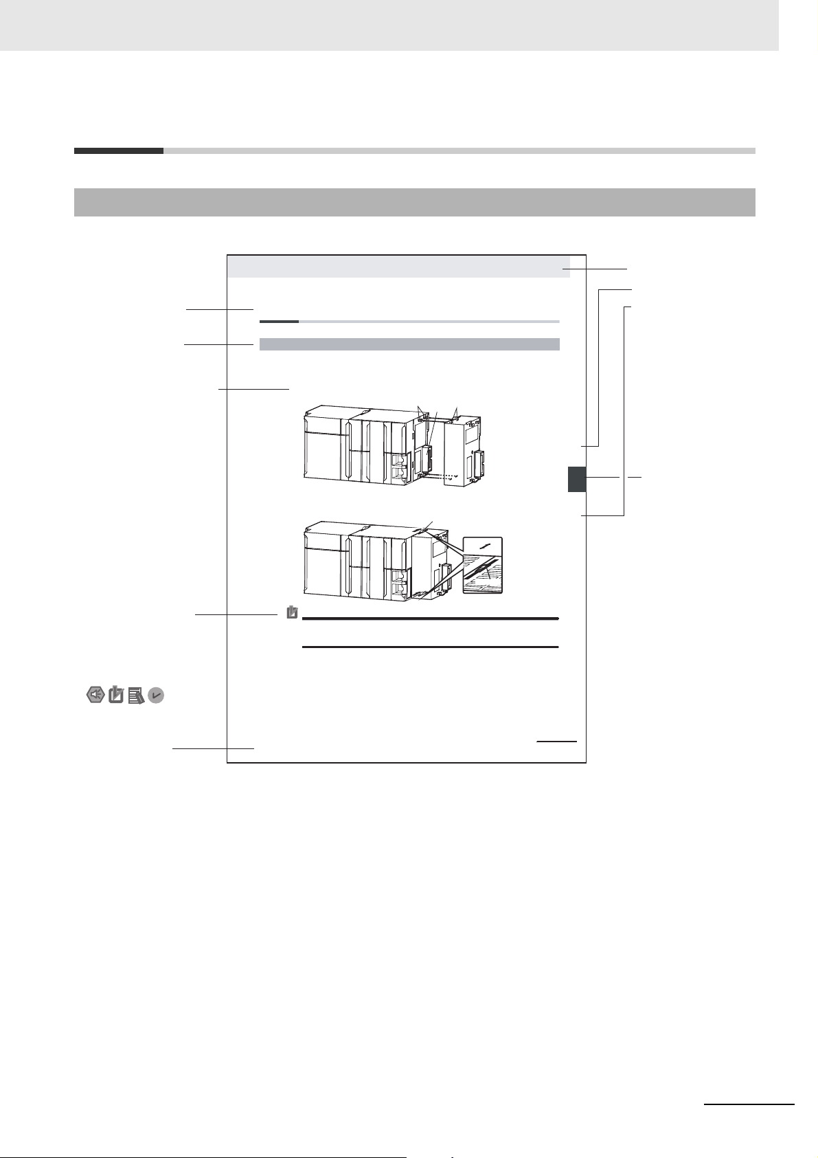
4-3 Mounting Units
The Units that make up an NJ-series Controller can be connected simply by pressing the Units together
and locking the sliders by moving them toward the back of the Units. The End Cover is connected in the
same way to the Unit on the far right side of the Controller.
1 Join the Units so that the connectors fit exactly.
2 The yellow sliders at the top and bottom of each Unit lock the Units together. Move the sliders
toward the back of the Units as shown below until they click into place.
Precautions for Correct UsePrecautions for Correct Use
4-3-1 Connecting Controller Components
Connector
Hook
Hook holes
Slider
Lock
Release
Move the sliders toward the back
until they lock into place.
Level 1 heading
Level 2 heading
Level 3 heading
Level 2 heading
A step in a procedure
Manual name
Special information
Level 3 heading
Page tab
Gives the current
headings.
Indicates a procedure.
Icons indicate
precautions, additional
information, or reference
information.
Gives the number
of the main section.
This illustration is provided only as a sample. It may not literally appear in this manual.
The sliders on the tops and bottoms of the Power Supply Unit, CPU Unit, I/O Units, Special I/O
Units, and CPU Bus Units must be completely locked (until they click into place) after connecting
the adjacent Unit connectors.
Page Structure
The following page structure is used in this manual.
Manual Structure
NJ-series SECS/GEM CPU Units User’s Manual (W528)
3
Page 6

Manual Structure
Special Information
Special information in this manual is classified as follows:
Precautions for Safe Use
Precautions on what to do and what not to do to ensure safe usage of the product.
Precautions for Correct Use
Precautions on what to do and what not to do to ensure proper operation and performance.
Additional Information
Additional information to read as required.
This information is provided to increase understanding or make operation easier.
Version Information
Information on differences in specifications and functionality for
and for different versions of the Sysmac Studio is given.
CPU Units with different unit versions
Note References are provided to more detailed or related information.
Precaution on Terminology
In this manual, “download” refers to transferring data from the Sysmac Studio to the physical Controller
and “upload” refers to transferring data from the physical Controller to the Sysmac Studio.
For the Sysmac Studio, synchronization is used to both upload and download data. Here, “synchronize”
means to au
physical Controller and transfer the data in the direction that is specified by the user.
The streams and functions that are defined in SEMI E5-0707 (SEM
dard 2 Message Content (SECS-II)) are given as
Function_name (Sstream_number
Example: Abort Transaction (S1,F0)
tomatically compare the data for the Sysmac Studio on the computer with the data in the
follows:
,Ffunction number)
I Equipme
nt Communications Stan-
4
NJ-series SECS/GEM CPU Units User’s Manual (W528)
Page 7
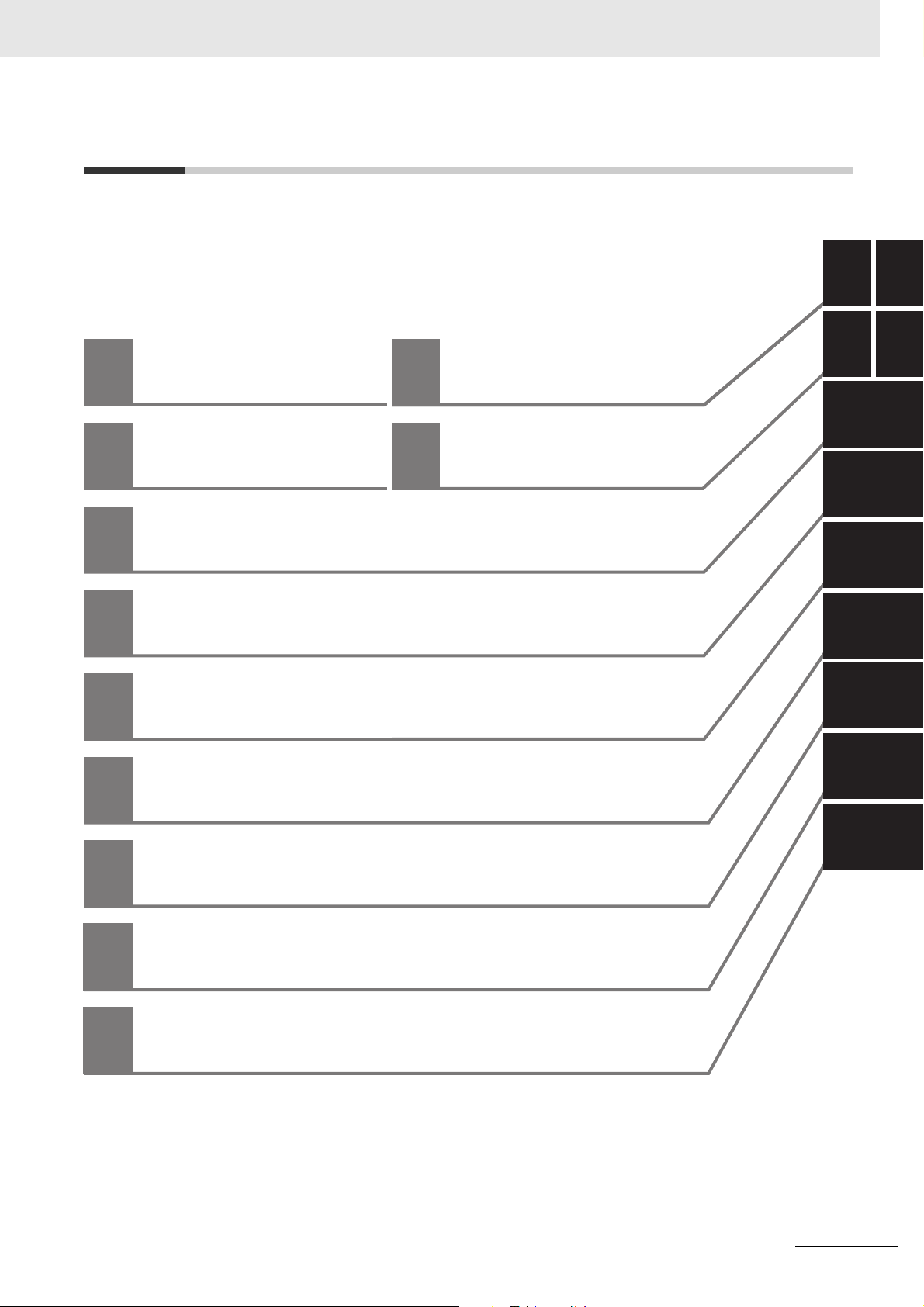
Sections in this Manual
Appendices
Index
SECS/GEM CPU Unit
Capabilities
1
2
3
4
5
6
7
8
9
1
A
6
5
4
3
7
8
9
I
I
A
2
I
System Configuration and
Functional Configuration
GEM Service Design Procedure
Functions Related to All GEM Services
Host Connection Function
GEM Service Logs
Functionality Other Than the GEM Services
SECS/GEM Configurator
Troubleshooting
Sections in this Manual
NJ-series SECS/GEM CPU Units User’s Manual (W528)
5
Page 8

CONTENTS
CONTENTS
Introduction ..............................................................................................................1
Intended Audience....................................................................................................................................... 1
Applicable Products..................................................................................................................................... 1
Relevant Manuals .....................................................................................................2
Manual Structure ......................................................................................................3
Special Information...................................................................................................................................... 4
Sections in this Manual ...........................................................................................5
Terms and Conditions Agreement........................................................................12
Warranty, Limitations of Liability ................................................................................................................ 12
Application Considerations ........................................................................................................................ 13
Disclaimers ................................................................................................................................................ 13
Safety Precautions .................................................................................................14
Precautions for Safe Use....................................................................................... 15
Precautions for Correct Use.................................................................................. 16
Regulations and Standards................................................................................... 18
Conformance to EC Directives .................................................................................................................. 18
Conformance to KC Standards.................................................................................................................. 19
Conformance to Shipbuilding Standards ................................................................................................... 19
Software Licenses and Copyrights ............................................................................................................ 19
Versions ..................................................................................................................20
Types of Versions ......................................................................................................................................20
Checking Versions..................................................................................................................................... 20
Unit Versions of CPU Units and Sysmac Studio Versions ......................................................................... 21
Related Manuals .....................................................................................................22
Terminology ............................................................................................................24
Revision History .....................................................................................................26
Section 1 SECS/GEM CPU Unit Capabilities
1-1 SECS/GEM CPU Unit Features ............................................................................................. 1-2
1-2 Standard Compliance of the SECS/GEM CPU Unit ............................................................ 1-4
1-2-1 SEMI Standard Compliance........................................................................................................1-4
1-2-2 SECS/GEM Standard Compliance..............................................................................................1-4
1-2-3 Supported SECS Messages ....................................................................................................... 1-5
Section 2 System Configuration and Functional Configuration
2-1 System Configuration ........................................................................................................... 2-2
2-2 Functional Configuration of SECS/GEM CPU Unit............................................................. 2-5
6
NJ-series SECS/GEM CPU Units User’s Manual (W528)
Page 9

2-3 Overview of GEM Service Operation ................................................................................... 2-7
2-3-1 SECS Messages When Host Sends the Primary Message........................................................ 2-7
2-3-2 SECS Messages When Equipment Sends the Primary Message.............................................2-11
2-3-3 Link Variables .....................................................................................................................
Section 3 GEM Service Design Procedure
3-1 Overview of GEM Service Design Procedure ..................................................................... 3-2
3-2 Using the SECS/GEM Configurator to Create the GEM Setting Data ...
CONTENTS
...... 2-15
............................ 3-4
3-3 Using the Sysmac Studio to Create the SECS/GEM Operation Programming
3-3-1 Starting the Sysmac Studio and Creating a Project .................................................................... 3-6
3-3-2 FTP Settings..........................................................................................................................
3-3-3 Creating the SECS/GEM Operation Programming..................................................................... 3-7
3-3-4 Restrictions When Defining Link Variables for User-defined Variables ...................................... 3-8
3-4 Debugging.............................................................................................................................. 3-9
Section 4 Functions Related to All GEM Services
4-1 Starting the GEM Services....................................................................................................4-2
4-1-1 Procedure to Change the GEM Service Status to Run............................................................... 4-2
4-1-2 Conditions That Prevent the GEM Service Status from Entering Run.
4-2 Ending the GEM Services ..................................................................................................... 4-3
4-2-1 Executing a Shutdown................................................................................................................ 4-3
4-2-2 Operation When Shutdown Processing Is Completed...........
..................................................... 4-3
4-3 GEM Service Status............................................................................................................... 4-4
4-3-1 GEM Service Status.................................................................................................................... 4-4
4-3-2 Changes in the GEM Service Status ..........................................................................................4-5
4-3-3 C
4-3-4 Relation between GEM Service Status and GEM Instructions .........
hecking the GEM Service Status.............................................................................................. 4-6
Section 5 Host Connection Function
................ 3-6
..... 3-7
....................................... 4-2
.......................................... 4-7
5-1 Basic Processing of the Host Connection Function.......................................................... 5-3
5-1-1 Starting and Pausing the Host Connection Function .................................................................. 5-3
5-1-2 Interlocks ............................................................................................................................
5-1-3 Transaction Processing ..............................................
5-1-4 Checking the Number of Buffered SECS Messages ................................................................ 5-12
................................................................ 5-6
........ 5-5
5-2 HSMS Communications ...................................................................................................... 5-13
5-2-1 Setting HSMS Conditions ......................................................................................................... 5-13
5-2-2 HSMS Communications Connection States ............................................................................. 5-14
5-2-3 Checking the HSMS Communications State ............................................................................ 5-15
5-3 Item Definitions.................................................................................................................... 5-16
5-4 Variable Data Definitions ....................................................................................................5-20
5-4-1 Types of Variable Data.............................................................................................................. 5-20
5-4-2 Variable Data Attributes and Initialization ................................................................................. 5-20
5-4-3 Variable Data List Structure and Link Variable Assignment Settings........................................ 5-21
5-4-4 Standard Variable Data............................................................................................................. 5-23
5-5 GEM Capabilities ................................................................................................................. 5-25
5-5-1 Communications State Model................................................................................................... 5-26
5-5-2 Control State Model.................................................................................................................. 5-30
3 Equipment Processing States................................................................................................... 5-36
5-5-
5-5-4 Event Notification...................................................................................................................... 5-39
5-5-5 Error Messages ........................................................................................................................ 5-42
6 Documentation.......................................................................................................................... 5-43
5-5-
5-5-7 Dynamic Event Report Configuration ....................................................................................... 5-44
NJ-series SECS/GEM CPU Units User’s Manual (W528)
7
Page 10

CONTENTS
5-5-8 Variable Data Collection............................................................................................................5-47
5-5-9 Trace Data Collection................................................................................................................5-48
5-5-10 Status Data Collection...............................................................................................................5-50
5-5-11 Alarm Management...................................................................................................................5-52
5-5-12 Host Commands ....................................................................................................................... 5-55
-5-13 Enhanced Remote Commands ................................................................................................. 5-59
5
5-5-14 Equipment Constants................................................................................................................5-61
5-5-15 Process Program Management ................................................................................................5-65
5-5-16
5-5-17 Equipment Terminal Service .....................................................................................................5-87
5-5-18 Clock ...................................................................................................................................
5-5-19 Limit Monitoring.........................................................................................................................5-92
5-5-20 Spooling ....................................................................................................................................5-95
Material Movement....................................................................................................................5-86
5-6 Message Settings .............................................................................................................. 5-101
5-6-1 GEM Standard Messages .......................................................................................................5-101
5-6-2 User-defined Messages ..........................................................................................................5-103
Section 6 GEM Service Logs
...... 5-90
6-1 GEM Service Logs ................................................................................................................. 6-2
6-1-1 Types of GEM Service Logs........................................................................................................6-2
6-1-2 Saving Destinations for GEM Service Logs ................................................................................6-2
6-1-3 Restrictions on GEM Service Logs .............................................................................................6-2
6-2 Application Procedures for the GEM Service Logs ........................................................... 6-4
6-2-1 Setting the Numbers of Records Saved in the GEM Service Logs .............................................6-4
6-2-2 Displaying the Contents of the GEM Service Logs .....................................................................6-4
6-3 Log Viewer Operations.......................................................................................................... 6-6
6-3-1 Installation of GEM Setting Tools ................................................................................................6-6
6-3-2 Starting and Stopping the Log Viewer ......................................................................................... 6-6
6-3-3 Configuration of the Main Window ..............................................................................................6-7
6-3-4 Procedure to Display a GEM Service Log...........................
6-3-5 Displaying the SECS Message Log ..........................................................................................6-12
6-3-6 Displaying the HSMS Communications Log .............................................................................6-15
6-3-7 Displaying the Execution Log....................................................................................................6-17
6-3-8 Filters
6-3-9 Saving the Current Settings ......................................................................................................6-18
6-3-10
6-3-11 Windows....................................................................................................................................6-22
6-3-12 Help.....................................................................................................................................
...............................................................................................................................
Outputting Logs to Files ........................................
.................................................................... 6-19
........................................................6-8
Section 7 Functionality Other Than the GEM Services
7-1 SD Memory Cards.................................................................................................................. 7-2
7-1-1 Directory Structure of the SD Memory Card................................................................................7-2
7-1-2 Restrictions When No SD Memory Card Is Inserted...................................................................7-2
7-1-3 Operation When Data Cannot Be Saved in the SD Memory Card..........
7-1-4 Operation When the SD Memory Card Is Replaced ................................................................... 7-3
7-2 Backup Functions ................................................................................................................. 7-5
7-2-1 Data That Is Backed Up..............................................................................................................7-5
7-2-2 Data That Is Not Backed Up .......................................................................................................7-5
7-2-3 Backup Functions for GEM Setting Data .................................................................................... 7-5
7-2-4 Compatibility between CPU Unit Models ....................................................................................
7-2-5 Compatibility between Versions of CPU Units ............................................................................7-6
7-2-6 Restrictions for Backup Function Execution................................................................................7-7
....................................7-2
......... 6-18
...... 6-22
7-6
8
NJ-series SECS/GEM CPU Units User’s Manual (W528)
Page 11

Section 8 SECS/GEM Configurator
8-1 Installing and Uninstalling the GEM Setting Tools............................................................. 8-3
8-1-1 Installation Precautions............................................................................................................... 8-3
8-1-2 Applicable Operating Systems for the GEM Setting Tools.....
8-1-3 Installed Application Software..................................................................................................... 8-3
8-1-4 Installation Procedure for the GEM Setting Tools ....................................................................... 8-4
8-1-5 Uninstallation Procedure for the GEM Setting Tools................................................................... 8-7
8-2 Starting and Exiting the SECS/GEM Configurator.............................................................. 8-8
8-2-1 Starting the SECS/GEM Configurator.........................................................................................8-8
8-2-2 Exiting the SECS/GEM Configurator ..........................................................................................8-9
8-3 Configuration of the SECS/GEM Configurator ................................................................. 8-10
8-3-1 Window Configuration............................................................................................................... 8-10
8-3-2 Menu Structure .........................................................................................................................
8-3-3 Operating Buttons..................................................................................................................... 8-14
8-4 Menu Bar Functions ............................................................................................................ 8-15
8-4-1 File............................................................................................................................................ 8-15
8-4-2 Build.......................................................................................................................................... 8-19
8-4-3 Controller .................................................................................................................................. 8-21
8-4-4 Tool ..................................................................................................................................
8-4-5 Documentation.......................................................................................................................... 8-30
8-4-6 Window..................................................................................................................................... 8-34
8-4-7 Help .................................................................................................................................
8-5 Toolbar Configuration ......................................................................................................... 8-36
8-6 Basic Operations on the List Menus ..............................
8-6-1 List Menu Dialog Boxes ............................................................................................................ 8-37
8-6-2 Setting Dialog Boxes ................................................................................................................ 8-38
8-6-3 Variable Dialog Boxes............................................................................................................... 8-40
8-7 Configuration ....................................................................................................................... 8-42
8-7-1 GEM Service Log...................................................................................................................... 8-42
8-8 HSMS Settings ..................................................................................................................... 8-43
8-8-1 HSMS Condition ....................................................................................................................... 8-43
8-9 Data Definition ..................................................................................................................... 8-45
8-9-1 Item........................................................................................................................................... 8-45
8-9-2 Equipment Constant (EC)......................................................................................................... 8-47
8-9-3 Status Variable (SV).................................................................................................................. 8-50
8-9-
4 Discrete Variable (DV) .............................................
8-9-5 List Structure Definitions........................................................................................................... 8-56
8-10 Model Settings ..................................................................................................................... 8-58
8-10-1 Communications State Model ................................................................................................... 8-58
8-10-2 Control State Model .................................................................................................................. 8-59
8-11 GEM Capability Settings .....................................................................................................8-60
8-11-1 Event Notification ...................................................................................................................... 8-61
8-11-2 Alarm Management .................................................................................................................. 8-69
-3 Host Command ......................................................................................................................... 8-72
8-11
8-1
1-4 Enhanced Remote Command .................................................................................................. 8-76
8-11-5 Equipment Constants ............................................................................................................... 8-80
-6 Process Program Management ................................................................................................8-81
8-11
8-11-7 Equipment Terminal Service.......................................
8-11-8 Limit Monitoring ..................................................................................................................
8-11-9 Spooling ..............................................................................................................................
8-12 Message Settings ................................................................................................................ 8-95
8-12-1 GEM Standard Messages......................................................................................................... 8-95
8-12-2 User-defined Messages............................................................................................................ 8-96
CONTENTS
..................................................... 8-3
.8-11
......... 8-26
......... 8-35
................................................... 8-37
................................................................. 8-53
.............................................................. 8-90
...... 8-92
...... 8-93
NJ-series SECS/GEM CPU Units User’s Manual (W528)
9
Page 12

CONTENTS
8-13 Confirm Settings................................................................................................................ 8-101
8-13-1 Item List...................................................................................................................................8-101
8-13-2 Message List...................................
8-13-3 Event List ................................................................................................................................8-102
8-13-4 Report List...............................................................................................................................8-103
8-13-5 Alarm List ............................................................................................................................
Section 9 Troubleshooting
9-1 Operation for Errors and Error Confirmation Methods...................................................... 9-2
9-2 Errors Related to SECS/GEM ............................................................................................... 9-3
9-2-1 Error Table...................................................................................................................................9-3
9-2-2 Error Descriptions .......................................................................................................................9-5
Appendices
A-1 GEM Instructions...................................................................................................................A-3
A-1-1 Table of GEM Instructions ...........................................................................................................A-3
A-1-2 Common Variables in GEM Instructions .............................
A-1-3 Common Precautions for Correct Use of GEM Instructions........................................................A-4
A-1-4 Error Codes That Occur for GEM Instruction Execution .............................................................A-5
A-1-5 Global Variables Used in the Sample Programming for GEM Instructions ...
A-1-6 Specifications of Individual GEM Instructions .............................................................................A-9
A-1-7 Events That Occur for GEM Instruction Execution..................................................................A-185
A-2 System-defined Variables.................................................................................................A-209
A-2-1 Package Version .....................................................................................................................A-210
A-2-2 Equipment Information............................................................................................................A-210
A-2-3 GEM Service Status................................................................................................................A
A-2-4 SECS Communications...........................................................................................................A-211
A-2-5 Interlocks.............................................................................................................................
A-2-6 HSMS Communications..........................................................................................................A-213
A-2-7 Communications State Model .................................................................................................A-216
A-2-8 Equipment Processing State.................
A-2-9 Control State Model.................................................................................................................A-216
A-2-10 Remote Control .......................................................................................................................A-217
A-2-11 Equipment Constants...............................................
A-2-12 Process Program Management ..............................................................................................A-218
A-2-13 Equipment Terminal Services......................................
A-2-14 Error Messages .......................................................................................................................
A-2-15 Clock ...................................................................................................................................
A-2-16 Spooling ..................................................................................................................................A-225
A-2-17 User-defined Messages ..........................................................................................................A-226
A-3 Correspondence between Formats and Data Types ......................................................A-228
........................................................................................8-102
.... 8-103
........................................................A-4
..............................A-6
-210
....A-213
..................................................................................A-216
...............................................................A-218
............................................................A-222
A-224
....A-225
Index
10
A-4 Designing Tasks to Use the GEM Services.......................
A-4-1 GEM Service Startup Time......................................................................................................A-229
A-4-2 Communications Performance of GEM Instructions ...............................................................A-230
A-4-3 Checking the Task Execution Time Ratio................................................................................A-232
..............................................A-229
A-5 Basic Specifications, Performance Specifications, and Functional Specifications ...A-233
A-6 Version Information...........................................................................................................A-234
A-6-1 Unit Version and GEM Service Version...................................................................................A-234
A-6-2 Unit Versions and Sysmac Studio Versions ............................................................................A-234
NJ-series SECS/GEM CPU Units User’s Manual (W528)
Page 13

CONTENTS
NJ-series SECS/GEM CPU Units User’s Manual (W528)
11
Page 14

Terms and Conditions Agreement
Terms and Conditions Agreement
Warranty, Limitations of Liability
Warranties
Exclusive Warranty
Omron’s exclusive warranty is that the Products will be free from defects in materials and workmanship for a period of twelve months from the date of sale by Omron (or such other period expressed in
writing by Omron). Omron disclaims all other warranties, express or implied.
Limitations
OMRON MAKES NO WARRANTY OR REPRESENTATION, EXPRESS OR IMPLIED, ABOUT
NON-INFRINGEMENT, MERCHANTABILITY OR FITNESS FOR A PARTICULAR PURPOSE OF
THE PRODUCTS. BUYER ACKNOWLEDGES THAT IT ALONE HAS DETERMINED THAT THE
PRODUCTS WILL SUITABLY MEET THE REQUIREMENTS OF THEIR INTENDED USE.
Omron further disclaims all warranties and responsibility of any type for claims or expenses based
on infringement by the Products or otherwise of any intellectual property right.
Buyer Remedy
Omron’s sole obligation hereunder shall be, at Omron’s election, to (i) replace (in the form originally
shipped with Buyer responsible for labor charges for removal or replacement thereof) the non-complying Product, (ii) repair the non-complying Product, or (iii) repay or credit Buyer an amount equal
to the purchase price of the non-complying Product; provided that in no event shall Omron be
responsible for warranty, repair, indemnity or any other claims or expenses regarding the Products
unless Omron’s analysis confirms that the Products were properly handled, stored, installed and
maintained and not subject to contamination, abuse, misuse or inappropriate modification. Return of
any Products by Buyer must be approved in writing by Omron before shipment. Omron Companies
shall not be liable for the suitability or unsuitability or the results from the use of Products in combination with any electrical or electronic components, circuits, system assemblies or any other materials or substances or environments. Any advice, recommendations or information given orally or in
writing, are not to be construed as an amendment or addition to the above warranty.
See http://www.omron.com/global/ or contact your Omron representative for published information.
Limitation on Liability; Etc
OMRON COMPANIES SHALL NOT BE LIABLE FOR SPECIAL, INDIRECT, INCIDENTAL, OR CONSEQUENTIAL DAMAGES, LOSS OF PROFITS OR PRODUCTION OR COMMERCIAL LOSS IN ANY
WAY CONNECTED WITH THE PRODUCTS, WHETHER SUCH CLAIM IS BASED IN CONTRACT,
WARRANTY, NEGLIGENCE OR STRICT LIABILITY.
Further, in no event shall liability of Omron Companies exceed the individual price of the Product on
which liability is asserted.
12
NJ-series SECS/GEM CPU Units User’s Manual (W528)
Page 15

Application Considerations
Suitability of Use
Omron Companies shall not be responsible for conformity with any standards, codes or regulations
which apply to the combination of the Product in the Buyer’s application or use of the Product. At
Buyer’s request, Omron will provide applicable third party certification documents identifying ratings
and limitations of use which apply to the Product. This information by itself is not sufficient for a complete determination of the suitability of the Product in combination with the end product, machine, system, or other application or use. Buyer shall be solely responsible for determining appropriateness of
the particular Product with respect to Buyer’s application, product or system. Buyer shall take application responsibility in all cases.
NEVER USE THE PRODUCT FOR AN APPLICATION INVOLVING SERIOUS RISK TO LIFE OR
PROPERTY WITHOUT ENSURING THAT THE SYSTEM AS A WHOLE HAS BEEN DESIGNED TO
ADDRESS THE RISKS, AND THAT THE OMRON PRODUCT(S) IS PROPERLY RATED AND
INSTALLED FOR THE INTENDED USE WITHIN THE OVERALL EQUIPMENT OR SYSTEM.
Terms and Conditions Agreement
Programmable Products
Omron Companies shall not be responsible for the user’s programming of a programmable Product, or
any consequence thereof.
Disclaimers
Performance Data
Data presented in Omron Company websites, catalogs and other materials is provided as a guide for
the user in determining suitability and does not constitute a warranty. It may represent the result of
Omron’s test conditions, and the user must correlate it to actual application requirements. Actual performance is subject to the Omron’s Warranty and Limitations of Liability.
Change in Specifications
Product specifications and accessories may be changed at any time based on improvements and other
reasons. It is our practice to change part numbers when published ratings or features are changed, or
when significant construction changes are made. However, some specifications of the Product may be
changed without any notice. When in doubt, special part numbers may be assigned to fix or establish
key specifications for your application. Please consult with your Omron’s representative at any time to
confirm actual specifications of purchased Product.
Errors and Omissions
Information presented by Omron Companies has been checked and is believed to be accurate; however, no responsibility is assumed for clerical, typographical or proofreading errors or omissions.
NJ-series SECS/GEM CPU Units User’s Manual (W528)
13
Page 16

Safety Precautions
Safety Precautions
Refer to the following manuals for safety precautions.
• NJ-series CPU Unit Hardware User’s Man
• NJ-series CPU Unit Software User’s
ual (Cat No. W500)
Manual (Cat No. W501)
14
NJ-series SECS/GEM CPU Units User’s Manual (W528)
Page 17

Precautions for Safe Use
Refer to the following manuals for precautions for safe use.
• NJ-series CPU Unit Hardware User’s
• NJ-series CPU Unit Software User’s Manual (Cat No. W501)
Manual (Cat No. W500)
Precautions for Safe Use
NJ-series SECS/GEM CPU Units User’s Manual (W528)
15
Page 18

Precautions for Correct Use
Precautions for Correct Use
Refer to the following manuals for safety precautions.
• NJ-series CPU Unit Hardware User’s Manual (Cat No. W500)
• NJ-series CPU Unit Software User’s Manual (Cat No. W501)
Host Connection Function
• Normal communications with the host may not be possible if incorrect settings are made for the host
connection function. Also, if you specify an incorrect host address, you may communicate with the
wrong host.
Make all settings carefully when you transfer the GEM setting data to the Controller.
• The host connection function will not operate if the variables assigned to the host connection function
do not exist in the Controller. Also, the host connection function may not operate normally if the data
types of the variables are not correct.
Confirm that the variables assigned to the host connection function agree with the variables in the
Controller before you transfer the GEM setting data to the controller.
• If you delete a variable used for the host connection function or change a variable name or data type,
make the same change in the variable assigned in the host connection function.
Testing Operation
• If you cannot connect to the host, check the value of the _GEM_HSMSState (HSMS Communications Status) system-defined variable. If the value of _GEM_HSMSState is FALSE, check the EtherNet/IP settings and cable wiring to see if they are correct.
• If you operate the system while connected to the host, use the Host Simulator to sufficiently check
functionality.
Operation
• If there are network problems during operation, the host will be disconnected and message communications will not be performed. Do not replace network devices or disconnect the LAN cable during
operation.
• If an SD Memory Card is not inserted, the GEM Service logs and spool data will not be recorded.
Also, it will not be possible to upload or download the GEM setting data between the SECS/GEM
Configurator and the CPU Unit.
Inset an SD Memory Card to use the host connection function.
• Stop the GEM Services before you replace the SD Memory Card. Do not upload or download the
GEM setting data between the SECS/GEM Configurator and the CPU Unit while you are replacing
the SD Memory Card.
• Before you turn OFF the power supply to the Controller, execute the GEM_Shutdown instruction and
save the GEM Service logs and spool data to the SD Memory Card.
If you do not execute the GEM_Shutdown instruction before you turn OFF the power supply to the
Controller, the GEM Service logs and spool data may be corrupted.
• To prevent loosing data for unexpected power interruptions, we recommend that you implement
countermeasures for power interruptions, such as installing an uninterruptible power supply.
16
Unit Replacement
• The GEM Service logs and spool data in the SD Memory Card are not backed up. If you replace the
CPU Unit, you cannot continue to use the previous GEM Service logs and spool data.
NJ-series SECS/GEM CPU Units User’s Manual (W528)
Page 19

Precautions for Correct Use
SD Memory Card Replacement
• If you replace the SD Memory Card, any existing GEM Service logs and spool data are deleted. If
necessary, use the Log Viewer to back up the GEM Service logs to a computer.
• Do not replace the SD Memory Card when the value of the _GEM_Spoo
system-defined variable is SPOOL ACTIVE. If you do, the sppl data will be deleted.
• We recommend that you use a new SD Memory Card when you re
replace the SD Memory Card with one that was previously used, format it to delete any old files.
lingState (Spooling State)
place the SD Memory Card. If you
NJ-series SECS/GEM CPU Units User’s Manual (W528)
17
Page 20

Regulations and Standards
Regulations and Standards
Conformance to EC Directives
Applicable Directives
• EMC Directives
• Low Voltage Directive
Concepts
EMC Directive
OMRON devices that comply with EC Directives also conform to the related EMC standards so that
they can be more easily built into other devices or the overall machine. The actual products have
been checked for conformity to EMC standards.*
Whether the products conform to the standards in the system used by the customer, however, must
be checked by the customer. EMC-related performance of the OMRON devices that comply with EC
Directives will vary depending on the configuration, wiring, and other conditions of the equipment or
control panel on which the OMRON devices are installed. The customer must, therefore, perform
the final check to confirm that devices and the overall machine conform to EMC standards.
* Applicable EMC (Electromagnetic Compatibility) standards are as follows:
EMS (Electromagnetic Susceptibility): EN 61131-2
EMI (Electromagnetic Interference): EN 61131-2
(Radiated emission: 10-m regulations).
Low Voltage Directive
Always ensure that devices operating at voltages of 50 to 1,000 VAC and 75 to 1,500 VDC meet the
required safety standards. The applicable directive is EN 61131-2.
Conformance to EC Directives
The NJ-series Controllers comply with EC Directives. To ensure that the machine or device in which
the NJ-series Controller is used complies with EC Directives, the Controller must be installed as follows:
• The NJ-series Controller must be installed within a control panel.
• You must use reinforced insulation or double insulation for the DC power supplies connected to
DC Power Supply Units and I/O Units.
• NJ-series Controllers that comply with EC Directives also conform to the Common Emission Standard (EN 61000-6-4). Radiated emission characteristics (10-m regulations) may vary depending
on the configuration of the control panel used, other devices connected to the control panel, wiring, and other conditions.
You must therefore confirm that the overall machine or equipment complies with EC Directives.
18
NJ-series SECS/GEM CPU Units User’s Manual (W528)
Page 21
Conformance to KC Standards
Observe the following precaution if you use NX-series Units in Korea.
Class A Device (Broadcasting Communications Device for Office Use)
This device obtained EMC registration for office use (Class A), and it is intended to be used in places
other than homes.
Sellers and/or users need to take note of this.
Conformance to Shipbuilding Standards
Regulations and Standards
The NJ-series Controllers comply with the following shipbuilding standards. Applicability to the shipbuilding standards is based on certain usage conditions. It may not be possible to use the product in
some locations. Contact your OMRON representative before attempting to use a Controller on a
ship.
Usage Conditions for NK and LR Shipbuilding Standards
• The NJ-series Controller must be installed within a control panel.
• Gaps in the door to the control panel must be completely filled or covered with gaskets or other
material.
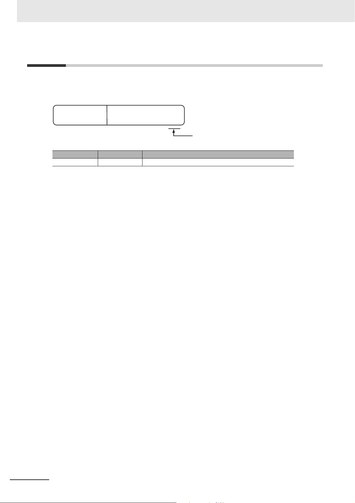
• The following noise filter must be connected to the power supply line.
Noise Filter
Manufacturer Model
Cosel Co., Ltd. TAH-06-683
Software Licenses and Copyrights
This product incorporates certain third party software. The license and copyright information associated with this software is available at http://www.fa.omron.co.jp/nj_info_e/.
NJ-series SECS/GEM CPU Units User’s Manual (W528)
19
Page 22
Versions
ID information label
NJ501
- 1340 Ver.1.00
PORT1 MAC ADDRESS:
GEM Ver.1.00
PORT2 MAC ADDRESS:
Lot No. 10513 A 1234
Model number
GEM Service
version
Lot number
Serial number MAC address
Unit version
Versions
Hardware and software versions are used to manage NJ-series Units. You can check versions on the
ID information labels attached to the Units or with the Sysmac Studio or a system-defined variable.
Types of Versions
There are two types of versions: the unit version and the GEM Service version. These versions are
managed separately, so either version can be updated without updating the other version.
Unit Version
The unit version applies to the hardware and software in the Unit. The unit version is updated each
time there is a change in hardware or software specifications. Even when two Units have the same
model number, they will have functional or capability differences if they have different unit versions.
GEM Service Version
The GEM Service version gives the version of the GEM Services that are implemented in the
SECS/GEM CPU Unit. The GEM Service version is updated when there are changes to the specifications for the GEM Services.
Checking Versions
You can check versions on the ID information labels or with the Sysmac Studio or a system-defined
variable.
Checking Versions on ID Information Labels
The version is given on the ID information label on the side of the product.
The ID information label on the NJ-series NJ501-1340 CPU Unit is shown below.
20
NJ-series SECS/GEM CPU Units User’s Manual (W528)
Page 23
Versions
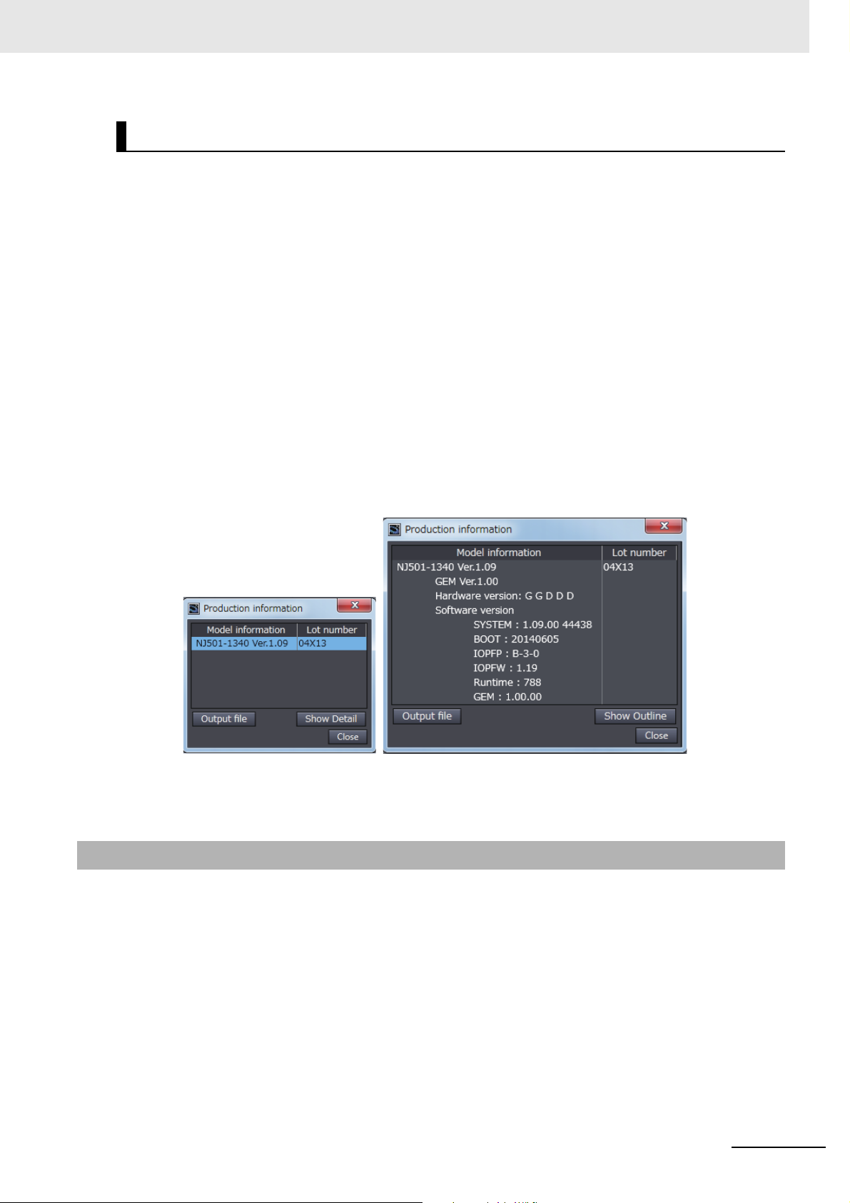
Outline View Detail View
Confirming Versions with the Sysmac Studio
You can use the Sysmac Studio to check versions.
Checking the Unit Version of a Unit
You can use the Unit Production Information while the Sysmac Studio is online to check the unit version of a Unit. You can do this for the CPU Unit, CJ-series Special I/O Units, and CJ-series CPU Bus
Units. You cannot check the unit versions of CJ-series Basic I/O Units with the Sysmac Studio.
Use the following procedure to check the unit version.
1 Double-click CPU/Expansion Racks under Configurations and Setup in the Multiview
Explorer. Or, right-click CPU/Expansion Racks under Configurations and Setup and select
Edit from the menu.
The Unit Editor is displayed.
2 Right-click any open space in the Unit Editor and select Production Information.
The Production Information Dialog Box is displayed.
3 Click the Show Detail or Show Outline Button at the lower right of the Production Information
Dialog Box.
The view will change between the production information details and outline.
The information that is displayed is different for the Outline View and Detail View. The Detail View
displays the unit version and GEM Service version. The Outline View displays only the unit version.
Unit Versions of CPU Units and Sysmac Studio Versions
The functions that are supported depend on the unit version of the NJ-series CPU Unit. The version
of Sysmac Studio that supports the functions that were added for an upgrade is also required to use
those functions.
For functions that are shared with the NJ-series CPU Units, refer to the NJ-series CPU Unit Soft-
ware User’s Manual (Cat. No. W501) for the relationship between the unit versions of the CPU Units
and the Sysmac Studio versions, and for the functions that are supported by each unit version.
Refer to A-6-2 Unit Versions and Sysmac Studio Versions for the relationship between the unit ver-
sions of the SECS/GEM CPU Unit and the Sysmac Studio versions.
NJ-series SECS/GEM CPU Units User’s Manual (W528)
21
Page 24

Related Manuals
Related Manuals
The followings are the manuals related to this manual. Use these manuals for reference.
Manual name Cat. No. Model numbers Application Description
NJ-series CPU Unit
Hardware User’s Manual
NJ-series CPU Unit Software User’s Manual
NJ-series Instructions
Reference Manual
NJ-series CPU Unit
Motion Control User’s
Manual
NJ-series Motion Control
Instructions Reference
Manual
NJ-series CPU Unit Builtin EtherCAT® Port
ser’
Manual
s
U
NJ-series CPU Unit Built-
in EtherNet/IP
User’s Manual
NJ-series Database Connection CPU Units User’s
Manual
TM
Port
W500 NJ501-
NJ301-
W501 NJ501-
NJ301-
W502 NJ501-
NJ301-
W507 NJ501-
NJ301-
W508 NJ501-
NJ301-
W505 NJ501-
NJ301-
W506 NJ501-
NJ301-
W527 NJ501-120 Using the database connec-
Learning the basic specifications of the NJ-series
CPU Units, including introductory information, designing, installation, and
maintenance. Mainly hardware information is provided.
Learning how to program
and set up an NJ-series
CPU Unit. Mainly software
information is provided.
Learning detailed specifications on the basic instructions of an NJ-series CPU
Unit.
Learning about motion control settings and programming concepts.
Learning about the specifications of the motion control
instructions that are provided by OMRON.
Using the built-in EtherCAT
port on an NJ-series CPU
Unit.
Using the built-in EtherNet/IP port on an NJ-series
CPU Unit.
tion service with NJ-series
Controllers
An introduction to the entire NJ-series system is
provided along with the following information on
the CPU Unit.
• Features and system configuration
• Introduction
• Part names and functions
• General specifications
• Installation and wiring
• Maintenance and inspection
Use this manual together with the NJ-series CPU
Unit Software User’s Manual (Cat. No. W501).
The following information is provided on a Controller built with an NJ501 CPU Unit.
• CPU Unit operation
• CPU Unit features
• Initial settings
• Programming based on IEC 61131-3 language
specifications
Use this manual together with the NJ-series CPU
Unit Hardware User’s Manual (Cat. No. W500).
The instructions in the instruction set (IEC 61131-3
specifications) are described. When programming, use this manual together with the NJ-series
CPU Unit Hardware User’s Manual (Cat. No.
W500) and NJ-series CPU Unit Software User’s
Manual (Cat. No. W501).
The settings and operation of the CPU Unit and
programming concepts for motion control are
described. Use this manual together with the NJ-
series CPU Unit Hardware User’s Manual (Cat.
No. W500) and NJ-series CPU Unit Software
User’s Manual (Cat. No. W501).
The motion control instructions are described.
When programming, use this manual together with
the NJ-series CPU Unit Hardware User’s Manual
(Cat. No. W500), NJ-series CPU Unit Software
User’s Manual (Cat. No. W501) and NJ-series
CPU Unit Motion Control User’s Manual (Cat. No.
W507).
Information on the built-in EtherCAT port is provided. This manual provides an introduction and
provides information on the configuration, features,
and setup.
Use this manual together with the NJ-series CPU
Unit Hardware User’s Manual (Cat. No. W500) and
NJ-series CPU Unit Software User’s Manual (Cat.
No. W501).
Information on the built-in EtherNet/IP port is provided. Information is provided on the basic setup,
tag data links, and other features.
Use this manual together with the NJ-series CPU
Unit Hardware User’s Manual (Cat. No. W500) and
NJ-series CPU Unit Software User’s Manual (Cat.
No. W501).
Describes the database connection service.
22
NJ-series SECS/GEM CPU Units User’s Manual (W528)
Page 25

Manual name Cat. No. Model numbers Application Description
NJ-series SECS Connection CPU Units User’s
Manual
NJ-series Troubleshooting Manual
Sysmac Studio Version 1
Operation Manual
W528 NJ501-1340 Using the GEM Services
with NJ-series Controllers
W503 NJ501-
NJ301-
W504 SYSMAC-
SE2
Learning about the errors
that may be detected in an
NJ-series Controller.
Learning about the operating procedures and functions of the Sysmac Studio.
Information is provided on the GEM Services.
Concepts on managing errors that may be
detected in an NJ-series Controller and information
on individual errors are described.
Use this manual together with the NJ-series CPU
Unit Hardware User’s Manual (Cat. No. W500) and
NJ-series CPU Unit Software User’s Manual (Cat.
No. W501).
Describes the operating procedures of the Sysmac
Studio.
Related Manuals
NJ-series SECS/GEM CPU Units User’s Manual (W528)
23
Page 26

Terminology
Terminology
Term Description
controller variable A variable that is registered on the SECS/GEM Configurator and can be imported
and exported between the SECS/GEM Co
GEM An acronym for Generic Equipment Model.
GEM capability An operation that is executed by the equipment and spe
ations are executed using SECS-II message sequences and sce
communications interface.
GEM instruction An instruction that is related to the GEM Services. GEM instructions are used in the
user program in the same way as other instructions.
GEM Service logs Functionality to record the operation of the GEM Services. The following logs are
recorded: a SECS message log, an HSMS communications log, and an execution
log. All of the logs are recorded on an SD Memory Card.
GEM Services Functionality based on SECS/GEM standard for host communications, GEM capa-
bility execution, communications logging, etc.
GEM setting data Data required for the GEM Services to operate.
GEM Setting Tool A generic name for Support Software for the SECS/GEM CPU Unit. The Log
Viewer and SECS/GEM Configurator are included.
host A computer that performs communications with SECS-compliant equipment, col-
lects equipment data, and sends equipment commands.
A system consisting of ERP, MES, etc., in a semiconductor manufacturing system.
The overall system consists of the host and manufacturing equipment.
host connection function A function to connect to a host based on SECS/GEM standards.
HSMS An acronym for High-speed SECS Message Services. This communications proto-
col uses Ethernet as the physical layer and TCP/IP as the transport layer.
link variable A variable that is used to pass data between a host connection function item and
the user program.
Log Vie
primary message A SECS message with an odd-number function code. A primary message is sent at
secondary message A SECS message with an even-number function code. A secondary message is
SECS An acronym for Semiconductor Equipment Communications Standard. A communi-
SECS-II SEMI standard E5. The same as SEMI Equipment Communications Standard 2
SECS/GEM An industry standard for communications b
SECS/GEM Conf
wer A Support Software application that is used to view logs recorded in the
SECS/GEM CPU Unit on a computer screen.
the beginning of a transaction.
sent in response to a primary message.
cations standard that was created for communications between semiconductor
manufacturi
Message Content (SECS-II).
This standard defines the formats and meanings of the messages that are sent
between the host and equipment. Messages are organized functionally by streams
and assigned codes. Functions are assigned within each stream. The combination
of the stream and function identifies a message.
ment in a semiconductor manufacturing system.
igurator A Support Software application that is used to set GEM setting data and
upload/downl
ng equipment and a host.
oad data to/from a SECS/GEM CPU Unit.
nfigurator and the Sysmac Studio.
cified in the GEM. All oper-
narios through the
etween a host
and manufacturing equip-
24
NJ-series SECS/GEM CPU Units User’s Manual (W528)
Page 27

Terminology
Term Description
SEMI An acronym for Semiconductor Equipment and Materials International. SEMI is an
international trade association that provides manufacturing equipment, materials,
and related services to the semiconductor, FPD, nanotechnology, MEMS, solar
power, and other industries.
stream and function
Note This manual uses terminology defined in SEMI standards. Refer to the SEMI standards for details on the
above terms and for information on terms that are not given above.
Identifiers of the contents of messages between host and equipment defined by
SECS-II.
NJ-series SECS/GEM CPU Units User’s Manual (W528)
25
Page 28
Revision History
Revision History
A manual revision code appears as a suffix to the catalog number on the front and back covers of the
manual.
Cat. No.
Revision code Date Revised content
01 September 2014 Original production
W528-E1-01
Revision code
26
NJ-series SECS/GEM CPU Units User’s Manual (W528)
Page 29

SECS/GEM CPU Unit Capabilities
A SECS/GEM CPU Unit is an NJ-series Standard CPU Unit that provides GEM Services. This section describes the capabilities that are provided by the GEM Services.
1-1 SECS/GEM CPU Unit Features . . . . . . . . . . . . . . . . . . . . . . . . . . . . . . . . . . . 1-2
1-2 Standard Compliance of the SECS/GEM CPU Unit . . . . . . . . . . . . . . . . . . . 1-4
1-2-1 SEMI Standard Compliance . . . . . . . . . . . . . . . . . . . . . . . . . . . . . . . . . . . . . . . 1-4
1-2-2 SECS/GEM Standard Compliance . . . . . . . . . . . . . . . . . . . . . . . . . . . . . . . . . . 1-4
1-2-3 Supported SECS Messages . . . . . . . . . . . . . . . . . . . . . . . . . . . . . . . . . . . . . . . 1-5
1
NJ-series SECS/GEM CPU Units User’s Manual (W528)
1 - 1
Page 30
1 SECS/GEM CPU Unit Capabilities
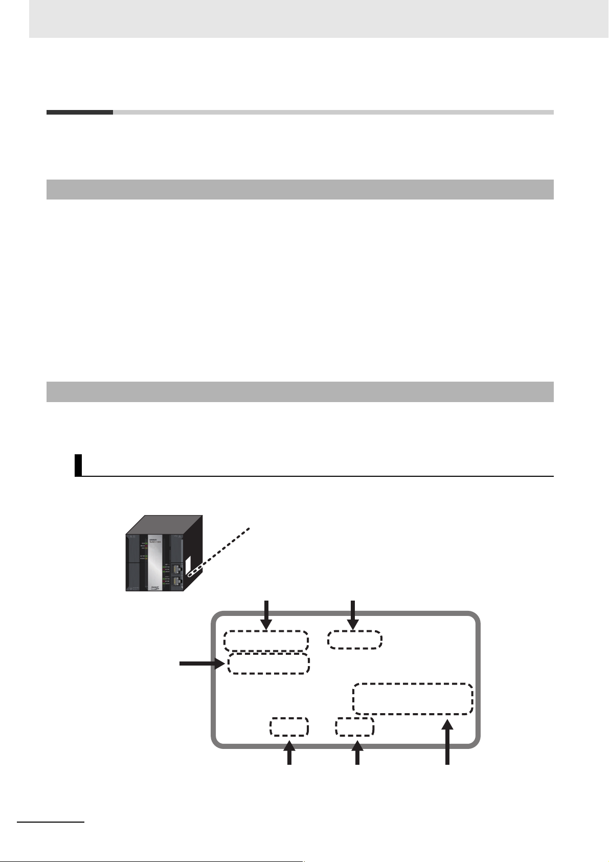
SECS/GEM CPU Unit
Semiconductor manufacturing equipment
SECS messages
Host
BS+
BD H
DB L
BS
-
1-1 SECS/GEM CPU Unit Features
The SYSMAC NJ-series Controllers are next-generation machine automation controllers that provide
the functionality and high-speed performance that are required for machine control.
They provide the safety, reliability, and maintainability that are required of indust
The NJ-series Controllers provide the functionality of previous OMRON PLCs, and they also provide
e functionality that is required for motion control. Synchronized control of I/O devices on high-speed
th
EtherCAT can be applied to safety devices, vision systems, motion equipment, discrete I/O, and more.
OMRON offers the new Sysmac Series of control de
vices design
fications and user interface specifications. The NJ-series Machine
ed with unified communications speci-
Automation Controllers are part of
the Sysmac Series. You can use them together with EtherCAT slaves, other Sysmac products, and the
Sysmac Studio Automation Software to achieve optimum functionality and ease of operation. With a
system that is created from Sysmac products, you can connect components and operate the system
through unified concepts and usability.
rial controllers.
In the same way as the NJ-series Standard CPU Unit
s, the SECS/GEM CPU Unit support
gramming languages defined in IEC 61131-3. It also provides GEM Se
rvices that can implement
s the pro-
streams and functions defined in the SEMI SECS/GEM standard.
Processing Communications between Semiconductor Equipment Control
Processes and a Host
The SECS/GEM CPU Unit provides both the functionality of an NJ-series Standard CPU Unit and
functionality compliant with the SECS/GEM standard to enable processing communications
between semiconductor equipment control processes and a host with just one Controller.
1 - 2
Programming without Worrying about SECS Message Formats
A host connection function handles SECS messages between the host and equipment so you do
not have to handle it directly in the user program. The host connection function is one of the GEM
Services. It is located between the host and user program and transmits commands sent from the
host to the user program and transmits commands from the user program to the host.
Therefore, the user does not need to interpret SECS
messages sent
from the host or prepare SECS
message formats to send to the host.
For example, the following procedure is used to exe
cute a host command using the remote com-
mand GEM capability.
1 The host sends Host Command Send (S2,F41).
2 The host connection function interprets the SECS message and informs the user program that a
host command was received.
3 The user processes the host command.
NJ-series SECS/GEM CPU Units User’s Manual (W528)
Page 31

1 SECS/GEM CPU Unit Capabilities
SECS/GEM CPU Unit
Communications
with host
User program
Instructions
Variables
Host connection function
4 When processing is completed, the user executes the Acknowledge Host Command
(GEM_AckHostCmd) GEM instruction.
5 The host connection function returns Host Command Acknowledge (S2,F42).
Commands from the user program to the host connection function ar
instructions. Information between the user program and host connection function is passed using
special variables called link variables.
e performed with special GEM
1-1 SECS/GEM CPU Unit Fea-
tures
1
User-defined Messages to Expand GEM Capabilities
In addition to the SECS messages defined in the SECS/GEM standard, the SECS/GEM CPU Unit
supports user-defined messages that are uniquely set by the user. This allows you to flexibly implement functions for unique user semiconductor
equipment.
Setting GEM Setting Data with the SECS/GEM Configurator
To use a SECS/GEM CPU Unit, you use the standard Sysmac Studio Support Software for
NJ-series Controllers, but you also use special Support Software called the SECS/GEM Configurator to make settings related to the GEM. You create the GEM setting data
figurator and then transfer it to the SECS/GEM CPU Unit.
with the SECS/GEM Con-
Work Separation for Host Communications Design and Control Sequence
Design
To execute an application with a SECS/GEM CPU Unit, you must design communications with the
host and you must design the control sequences, including I/O controls. Both of these can be performed in parallel because settings for host communications are performed on the SECS/GEM Configurator and control sequence programming is performed on the Sysmac Studio.
Complete Logging Functions
The SECS/GEM CPU Unit records three different logs on an SD Memory Card. You can check
these logs from the Log Viewer or from the user program. Checking the logs simplifies troubleshooting when unintended operation occurs when building or operating the system.
• The SECS message log records the SECS messages sent between
• The HSMS communications log records HSMS communications executed between the host and
equipment.
•
The execution log records GEM instruction execution in the user program and the writing of
shared va
riables by the host connection function.
the host and equipment.
NJ-series SECS/GEM CPU Units User’s Manual (W528)
1 - 3
Page 32

1 SECS/GEM CPU Unit Capabilities
1-2 Standard Compliance of the
SECS/GEM CPU Unit
The SECS/GEM CPU Unit complies with SEMI and SECS/GEM standards.
1-2-1 SEMI Standard Compliance
The SECS/GEM CPU Unit complies with the following SEMI standards.
Standard number Standard name
E37-0303 High-speed SECS Message Services (HSMS) Generic Services
E37.1-0
E5-0707 SEMI Equipment Communicati
E30-0307 Generic Model for Communications and Control of Manufacturing Equip-
*1. E42 recipes, large process programs, and E139 recipes are not supported.
702 High-speed SECS Message Services Single-session Mode (HSMS-SS
or HSMS-SSS)
(SECS-II)
ment (GEM)
ons Standard 2 Message
*1
Content
1-2-2 SECS/GEM Standard Compliance
The
SECS/GEM CPU Unit complies with the following SECS/GEM
GEM compliance
Fundamental GEM requirement Implemented GEM compliant
State models Yes No Ye s No
Equipment processing states Yes No
Host-initiated S1,F13/F
Event notification Yes No
On-line identifica
Error messages Ye
Control (o
Documentation Yes
Establish communications Yes No Ye s No
Dynamic event report configuration Yes No Yes No
Variab
Trace dat
Stat
Alarm management Yes No Ye
Remote control Yes No Ye s No
Equ
Process recipe management Yes No Process programs
Material movement Yes
Equipment termi
Clock Yes No Ye
Limits
perator-initiated) Yes No
Additional capabilities Implemented GEM compliant
le data collection Yes No Ye s No
a collection Yes No Yes No
us data collection Yes No Ye s No
ipment constant
monitoring Yes No Ye s No
14 scenario Yes No
tion Yes No
s No
No
s Yes No Ye s No
No Yes No
nal services Yes No Ye s No
standards.
s No
No
Yes
E42 recipes
Ye
s
No
E139 recipes
Ye
No
s
s No
1 - 4
NJ-series SECS/GEM CPU Units User’s Manual (W528)
Page 33

1 SECS/GEM CPU Unit Capabilities
1-2 Standard Compliance of the
GEM compliance
Fundamental GEM requirement Implemented GEM compliant
Spooling Ye s No Yes No
Control (host-initiated) Yes No Ye s No
1-2-3 Supported SECS Messages
The SECS messages that are supported by the SECS/GEM CPU Unit are listed in the following table.
In addition to these SECS messages, the use of user-defined messages is also supported.
Communica-
Stream Function
Sx F0 H↔E Abort Transaction
S1:
Equipment Status
F1 H↔E Are You There Request
F2 H↔E On Line Data
F3 H→E Selected Equipment Status Request
F4 H←E Selected Equipment Status Data
F11 H→E Status Variable Namelist Request
F12 H←E Status Variable Namelist Reply
F13 H↔E Establish Communications Request
F14 H↔E Establish Communications Request Acknowledge
F15 H→E Request OFF-LINE
F16 H←E OFF-LINE Acknowledge
F17 H→E Request ON-LINE
F18 H←E ON-LINE Acknowledge
tions direction
H: Host
E: Equipment
SECS/GEM CPU Unit
1
1-2-3 Supported SECS Messages
Function name
NJ-series SECS/GEM CPU Units User’s Manual (W528)
1 - 5
Page 34

1 SECS/GEM CPU Unit Capabilities
Stream Function
S2:
Equipment Control
and Diagnostics
S5:
Exception Handling
S6:
Data Collection
F13 H→E Equi
F14 H←E Equipment Constant Data
F15 H→E New Equipment Constant Send
F16 H←E New Equipment Constant Acknowledge
F17 H↔E Date and Time Request
F18 H↔E Date and Time Data
F23 H→E Trace Initialize Send
F24 H←E Trace Initialize Acknowledge
F25 H→E Loopback Diagnostic Request
F26 H←E Loopback Diagnostic Data
F29 H→E Equipment Constant Namelist Request
F30 H←E Equipment Constant Namelist
F31 H→E Date and Time Set Request
F32 H←E Date and Time Set Acknowledge
F33 H→E Define Report
F34 H←E Define Report Acknowledge
F35 H→E Link Event Report
F36 H←E Link Event Report Acknowledge
F37 H→E Enable/Disable Event Report
F38 H←E Enable/Disable Event Report Acknowledge
F39 H→E Multi-block Inquire
F40 H←E Multi-block Grant
F41 H→E Host Command Send
F42 H←E Host Command Acknowledge
F43 H→E Reset Spooling Streams and Functions
F44 H←E Reset Spooling Acknowledge
F45 H→E Define Variable Limit Attributes
F46 H←E Variable Limit Attribute Acknowledge
F47 H→E Variable Limit Attribute Request
F48 H←E Variable Limit Attributes Send
F49 H→E Enhanced Remote Command
F50 H←E Enhanced Remote Command Acknowledge
F1 H←E Alarm Report Send
F2 H→E Alarm Report Acknowledge
F3 H→E Enable/Disable Alarm Send
F4 H←E Enable/Disable Alarm Acknowledge
F5 H→E List Alarms Request
F6 H←E List Alarms Data
F7 H→E List Enabled Alarm Request
F8 H←E List Enabled Alarm Data
F1 H←E Trace Data Send
F2 H→E Trace Data Acknowledge
F11 H←E Event Report Send
F12 H→E Event Report Acknowledge
F15 H→E Event Report Request
F16 H←E Event Report Data
F19 H→E Individual Report Request
F20 H←E Individual Report Data
F23 H→E Request Spooled Data
F24 H←E
Communica-
tions direction
H: Host
E: Equipment
Function name
pment Constant Request
Request Spooled Data Acknowledgement Send
1 - 6
NJ-series SECS/GEM CPU Units User’s Manual (W528)
Page 35

1 SECS/GEM CPU Unit Capabilities
1-2 Standard Compliance of the
Stream Function
S7:
Process Program
Management
S9:
System Errors
S10:
Terminal Services
Communica-
tions direction
H: Host
E: Equipment
F1 H↔E Process Program L
F2 H↔E Process Program Load Grant
F3 H↔E Process Program Send
F4 H↔E Process Program Acknowledge
F5 H↔E Process Program Request
F6 H↔E Process Program Data
F17 H→E Delete Process Program Send
F18 H←E Delete Process Program Acknowledge
F19 H→E Current EPPD Request
F20 H←E Current EPPD Data
F23 H↔E Formatted Process Program Send
F24 H↔E Formatted Process Program Acknowledge
F25 H↔E Formatted Process Program Request
F26 H↔E Formatted Process Program Data
F27 H←E Process Program Verification Send
F28 H→E Process Program Verification Acknowledge
F1 H←E Unrecognized Device ID
F3 H←E Unrecognized Stream Type
F5 H←E Unrecognized Function Type
F7 H←E Illegal Data
F9 H←E Transaction Timer Timeout
F11 H←E Data Too Long
F13 H←E Conversation Timeout
F1 H←E Terminal Request
F2 H→E Terminal Request Acknowledge
F3 H→E Terminal Display, Single
F4 H←E Terminal Display, Single Acknowledge
F5 H→E Terminal Display, Multi-block
F6 H←E Terminal Display, Multi-block Acknowledge
F7 H←E
Multi-block Not Allowed
Function name
oad Inquire
SECS/GEM CPU Unit
1
1-2-3 Supported SECS Messages
NJ-series SECS/GEM CPU Units User’s Manual (W528)
1 - 7
Page 36

1 SECS/GEM CPU Unit Capabilities
1 - 8
NJ-series SECS/GEM CPU Units User’s Manual (W528)
Page 37

System Configuration and Functional Configuration
This section describes the system configuration of an NJ-series Controller in which a
SECS/GEM CPU Unit is connected and the functional configuration of the SECS/GEM
CPU Unit. It also introduces the GEM Services, which are the most characteristic functional configuration element of the SECS/GEM CPU Unit.
2-1 System Configuration . . . . . . . . . . . . . . . . . . . . . . . . . . . . . . . . . . . . . . . . . . 2-2
2-2 Functional Configuration of SECS/GEM CPU Unit . . . . . . . . . . . . . . . . . . . 2-5
2
2-3 Overview of GEM Service Operation . . . . .
2-3-1 SECS Messages When Host Sends the Primary Message . . . . . . . . . . . . . . . 2-7
2-3-2 SECS Messages When Equipment Sends the Primary Message . . . . . . . . . .2-11
2-3-3 Link Variables . . . . . . . . . . . . . . . . . . . . . . . . . . . . . . . . . . . . . . . . . . . . . . . . . 2-15
. . . . . . . . . . . . . . . . . . . . . . . . . 2-7
NJ-series SECS/GEM CPU Units User’s Manual (W528)
2 - 1
Page 38

2 System Configuration and Functional Configuration
Equipment
Host
SECS/GEM CPU Unit
Ethernet network
EtherCAT
Built-in EtherCAT port
Built-in EtherNet/IP port
Peripheral USB port
HUB
UPS (uninterruptible
power supply)
SD Memory
Card
EtherCAT slaves
HMI
Computer (GEM
Setting Tools)
Computer
(Sysmac Studio)
SECS/G
t
y)
2-1 System Configuration
The I/O ports of a SECS/GEM CPU Unit are the same as the I/O ports of an NJ-series Standard CPU
Unit. Therefore, the connection methods for EtherCAT slaves and HMIs are the same as an NJ-series
Controller in which a Standard CPU Unit is connected.
A typical system configuration for an NJ-series Control
is shown below.
UB
EM CPU Unit
eripheral USB port
Built-in EtherNet/IP port
ler in whic
h a SECS/GEM CPU Unit is connected
MI
D Memory
Card
UPS (uninterruptible
power suppl
Host
The host computer performs communications with the equipment, collects data from the equipment,
and sends commands to the equipment.
Equipment
The equipment manufacturers semiconductors, FPDs, etc. It performs communications with the
host. The NJ-series Controller in which a SECS/GEM CPU Unit is connected is mounted in the
equipment.
SECS/GEM CPU Unit
The SECS/GEM CPU Unit is an NJ-series NJ501-1300 Standard CPU Unit to which GEM Services
were added. The GEM Services provide functionality defined in the SECS/GEM standard. Therefore, the dimensions, power consumption, operating enviro
capabilities of the SECS/GEM CPU Unit are the same as the NJ501-1300 except for the specifications for the SECS/GEM standard. There is no NJ501-1300 functionality that is n
NJ501-1340.
For NJ501-1300 specifications, refer to the NJ-series CPU Unit Hardware User
W500) and NJ-series CPU Unit Software User’s Manual (Cat. No. W501).
Built-in EtherCAT por
therCAT
therCAT slaves
nment, I/O ports, functions, and other
ot supported by the
’s Manual (Cat. No.
2 - 2
NJ-series SECS/GEM CPU Units User’s Manual (W528)
Page 39

2 System Configuration and Functional Configuration
Precautions for Correct Use
The unique specifications of the SECS/GEM CPU Unit are introduced below.
Item Description
Model number NJ501-1340
Versions
GEM Services Functionality based on SECS/GEM standard for host communica-
SECS message
communications
*1. Refer to Versions on page 20 for the methods to check the versions.
*2. The maximum length of a SECS message for process program management is 257 Kbytes.
Applicable port Built-in EtherNet/IP port
Communications pro-
tocol
Applicable standards HSMS-SS
Number of connected
hosts
Maximum message
[Kbytes]
length
Both a unit version and a GEM Service version are managed.
tions, GEM Service logging, etc.
TCP/IP
1
*2
256
*1
2-1 System Configuration
2
SD Memory Cards
The SECS/GEM CPU Unit supports the same SD Memory Cards as the NJ-series Standard CPU
Units. The GEM Service logs and spool data used in the GEM Services are stored on an SD Memory Card. You can insert an SD Memory Card in the SECS/GEM C
PU Unit.
Built-in EtherNet/IP Port
The SECS/GEM CPU Unit has the same built-in EtherNet/IP port as on an NJ-series Standard CPU
Unit. It is used to perform communications with the host. Host communications for the GEM Services operate as one TCP/IP function of the built-in EtherNet/IP. You can use the other functions of
the built-in Eth
erNet/IP, such as tag data links, at the same time as the GEM Services.
If you use the Network Configurator with the SECS/GEM CPU Unit, set the CPU Unit model on
the Network Configurator to the NJ501-1300.
Built-in EtherCAT Port
The SECS/GEM CPU Unit has the same built-in EtherCAT port as on an NJ-series Standard CPU
Unit. It is not directly related to the GEM Services.
GEM Setting Tools
“GEM Setting Tools” is a generic name that includes the SECS/GEM Configurator that you use to
create the setting data for the GEM Services and the Log Viewer that you use to display the GEM
Service logs. The GEM Setting Tool Support Software is independent of the Sysmac Studio Support
Software. The computer in which the GEM Setting Tools are installed is connected to the built-in
EtherNet/IP port on the SECS/GEM CPU Unit.
You can install the SECS/GEM Configurator and the Sysmac Studio on the same computer.
The basic specifications of the GEM Setting
Item Specification
Name SECS/GEM Configurator
Model number WS02-GCTL1
NJ-series SECS/GEM CPU Units User’s Manual (W528)
ls are given in the following table.
Too
2 - 3
Page 40

2 System Configuration and Functional Configuration
Precautions for Correct Use
Item Specification
Connection port on SECS/GEM CPU Unit Built-in EtherNet/IP port or peripheral USB port
Number of connected Units 1
Communications protocol TCP/IP
Communications port Always 9700.
Data transfer method
The SECS/GEM Configurator provides the following functionality.
• Creating, editing, and saving GEM setting data
• Uploading and downloading GEM setting data
• Importing and exporting controller variables
• Creating SML files
The contents of the GEM setting data that is uploaded with the SECS/GEM Configurator is the
same as the contents of the GEM setting data that was previously downloaded with the
SECS/GEM Configurator. Even if the settings in the downloaded GEM setting data were
changed by the user program or host, the changes will not be reflected in the uploaded GEM
setting data.
FTP
The Log Viewer provides the following functionality.
• Uploading GEM Service logs
• Displaying GEM Service logs
• Outputting GEM Service log files
Sysmac Studio
You use the same Sysmac Studio Support Software with the SECS/GEM CPU Unit as you do with
an NJ-series Standard CPU Unit. The computer in which the Sysmac Studio is installed is connec
to the peripheral USB port or built-in EtherNet/IP port on the SECS/GEM CPU Unit.
The SECS/GEM CPU Unit is supported by Sysmac Studio ve
rsion 1.10 or higher. The following
functionality is enabled if you select the model number of the SECS/GEM CPU Unit (NJ501-1340) in
Select Device Area of Project Properties Dialog Box.
• Using system-defined variables re
lated to GEM
• Using GEM instructions
• Adding GEM setting data in the data to back up
UPS
A UPS is an uninterruptible power supply. It provides power to the SECS/GEM CPU Unit during
power interruptions until the power supply to the SECS/GEM CPU Unit can be turned OFF safely.
ted
2 - 4
NJ-series SECS/GEM CPU Units User’s Manual (W528)
Page 41

2 System Configuration and Functional Configuration
Host
Log Viewer
SECS/GEM
Configurator
Sysmac Studio
Importing and
exporting variables
User program variable definitions and algorithms
Ethernet network
(8)
(9)
(10)
GEM setting
data
(15)
Spool
file
(7)
GEM Service
logs
(6)
User
program
Link variables
(1)
(11)
(12)
(13)
(14)
Interlock variables
GEM instructions
Transaction
Processing Flag
(2)
Host connection function
GEM Services
SECS/GEM CPU Unit
GEM
capabilities
SECS message
communications processing
HSMS communications
processing
(3)
(4)
(5)
2-2 Functional Configuration of
SECS/GEM CPU Unit
2-2 Functional Configuration of SECS/GEM
The functional configuration of the SECS/GEM CPU Unit is shown in the following figure.
CPU Unit
2
The elements in the above figure are described in the following table. Refer to the reference pages for
detailed infor
No. Element Description Reference
(1) User program The user program is the same as for an
(2) Host connection function This software handles SECS messages with
(3) GEM capabilities This software processes the GEM capabili-
(4) SECS message commu-
NJ-series SECS/GEM CPU Units User’s Manual (W528)
(5) HSMS communi
(6) GEM Service logs This i
(7) Spool file The spool file contains SECS messages that
(8) Log
(9) SECS/GEM Configurator This Support Software is used to set the
mation on the elements.
nications processing
processing
Viewer This Support Software displays the contents
cations
NJ-series Standard CPU Unit
the host and exchanges data with the user
program.
ties.
This software processes SECS message
communications.
This software processes HSMS communications.
s a generic name for the HSMS communications log, SECS message log, and
execution log.
were qu
ity while communications were not being
performed b
of the GEM Service logs.
GEM setting data.
eued for the GEM spooling capabil-
etween the
.
host and equipment.
---
5-1 Basic Processing of the
Host Connection Function
on page 5-3
5-5 GEM Capabilities on
page 5-
---
5-2 HSMS Communications on page 5-13
Section 6 GEM Service
Logs
5-5-20 Spooling on page
5-95
6-3 Log Viewer Operations
on page 6-6
Section 8 SECS/GEM Configurator
25
2 - 5
Page 42

2 System Configuration and Functional Configuration
No. Element Description Reference
(10) Sysmac Studio This Support Software is used to perform
settings and programming for NJ-series
CPU Units. You can import and export user
program variable definitions to share them
between the Sysmac Studio and the
SECS/GEM Configurator.
(11) Link variables These variables are used to share informa-
tion between the user program and host
conn
ection function.
(12) Transaction processing
flag
(13) Interlock variables These variables are used
(14) GEM instructions These special instructions are used
(15) GEM setting data This setting data is related to the GEM Ser-
This variable is used by the host connection
function
SECS message was received from the host.
tion of commands output to the host connection function from the host.
GEM Services.
vices.
to tell the user program
that a
to prohibit execu-
for the
---
2-15
page 5-6
page 5-12
ariables on
2-3-3 Link V
page
5-1-3 Transaction Processing on
5-1-4 Checking the Number of Buffered SECS Messages on
A-1 GEM Instructions on
e A-3
pag
---
2 - 6
NJ-series SECS/GEM CPU Units User’s Manual (W528)
Page 43

2 System Configuration and Functional Configuration
2-3 Overview of GEM Service Operation
The GEM Services perform SECS message communications with the host according to the
SECS/GEM standard. There are the following two types of SECS messages exchanged between the
host and equipment.
• SECS messages when host sends the primary message
• SECS messages when equipment sends the primary message
From the viewpoint of the processing performed by the equipment, there are the following two types of
SECS messages.
• SECS messages processed by the GEM services alone
• SECS messages processed jointly by the GEM services and user program
If processing is performed jointly by the GEM Services
pass data between the GEM Services and the user program are called link variables.
and user pr
2-3-1 SECS Messages When Host Sends the Primary Message
ogram, the variables that are used to
2-3 Overview of GEM Service Operation
2
2-3-1 SECS Messages When Host Sends the Primary Message
When the host sends the primary message, the GEM Services r
Some SECS messages are processed just by the GEM Services and some are processed jointly by the
GEM Services and user program.
SECS Messages Processed by the GEM Services Alo
After the GEM Services receive the SECS message from the host, the me
ically without notifying the user program. Therefore, you do not have
user program.
eceive the message and interpret it.
ne
ssage is processed automat-
to perform any processing in the
SECS Messages Processed Jointly by the GEM Services and User
Program
The processing performed by the GEM Services and use
r program is as follows:
1 The GEM Services receive the primary message from the host.
2 The GEM Services use the transaction processing flag to notify the user program that a SECS
message was received.
3 The user program performs the required processing for the SECS message.
4 The user program uses a GEM instruction to notify the GEM Services that it performed the pro-
cessing.
5 The GEM Services return a secondary message.
If an interlock variable is used to prohibit the execution
the user program. The GEM Services automatically return a secondary message saying that the execution of processing is not permitted.
The primary SECS messages that the host can send are listed in the following table. The table also tells
proc
essing is performed by the GEM Services alone or jointly by the GEM Services and user pro-
if
gram, and the table gives any related transaction processing flag and
is performed jointly by the GEM Services and user program, the GEM instructions that are executed in
the user program are given in the Processing column.
NJ-series SECS/GEM CPU Units User’s Manual (W528)
of processing, the GEM Services do not notify
interlock variables. If processing
2 - 7
Page 44

2 System Configuration and Functional Configuration
Stream Function Function name Processing
S1: Equipment Status
F1 Are You There Request GEM Services --- --F2 On Line Data
F3 Selected Equipment Sta-
tus Request
F4 Selected Equipment Sta-
tus Data
F11 Status Variable Namel-
ist Request
F12 Status Variable Namel-
ist Reply
F13 Establish Communica-
tions Request
F14 Establish Communica-
tions Request Acknowl-
edge
F15 Request OFF-LINE GEM Services --- --F16 OFF-LINE Acknowledge
F17 Request ON-LINE GEM Services --- _GEM
F18 ON-LINE Acknowledge
GEM Services --- ---
GEM Services --- ---
GEM Services --- ---
Transaction
processing flag
Interlock vari-
able
_Interlock
_ControlState
2 - 8
NJ-series SECS/GEM CPU Units User’s Manual (W528)
Page 45

2 System Configuration and Functional Configuration
2-3 Overview of GEM Service Operation
Stream Function Function name Processing
S2: Equipment Control and
Diag
nos-
tics
F13 Equip
F14 Equipm
F15 New Equipment Con-
F16 New Equipment Con-
F17 Date and Time Request GEM Services --- _GEM
F18 Date and Time Data
F23 Trace Initialize Send GEM Services --- --F24 Trace Initialize Acknowl-
F29 Equipment Constant
F30 Eq
F31 Date and Time Set
F32 Date an
F33 Define Report GEM Services --- --F34 Define Report Acknowl-
F35 Link Event Report GEM Services --- --F36 Link Event Report
F37 Enabl
F38 Enable
F39 Multi-block Inquire GEM Services --- --F40 Multi-block Grant
F41 Host Command Send Jointly:
F42 Host Command
F43 Reset Spoo
F44 Re
F45 Define Variable Limit
F46 Variable Limit Attribute
F47 Varia
F48 Variab
F49 Enhanced Remote Com-
F50 Enhanced Remote Com-
ment Constant
Request
ent Constant
Data
stant Send
stant Acknowledge
edge
Na
melist Request
uipment Constant
Namelist
Request
d Time Set
Acknowledge
edge
Acknowledge
e/Disable Event
Report
/Disable Event
Report Acknowledge
Acknow
and Functions
Acknowledge
Attributes
Acknowledge
Request
Send
mand
mand Acknowledge
ledge
ling Streams
set Spooling
ble Limit Attribute
le Limit Attributes
GEM Services --- ---
GEM Services --- ---
GEM Services --- ---
GEM Services --- ---
GEM Services --- ---
GEM_AckHost
Cmd
GEM Services --- ---
GEM Services --- ---
GEM Services --- ---
Jointly:
GEM_AckEnha
ncedCmd
Transaction
processing flag
_GEM_Busy
HostCmd
_G
EM_Busy
EnhancedRmt
Cmd
Interlock vari-
able
_Interlock
_Time
_GEM
_Interlock
_HostCmd
_GEM
_Interlock_
EnhancedRmt
Cmd
2
2-3-1 SECS Messages When Host Sends the Primary Message
NJ-series SECS/GEM CPU Units User’s Manual (W528)
2 - 9
Page 46

2 System Configuration and Functional Configuration
Stream Function Function name Processing
S5: Exception Handling
S6: Data
Collection
S7: Process Pr
ogram
Mana
ge-
ment
S9: System Errors
F3 Enable/Disable Alarm
Send
F4 Enable/Disable Alarm
Acknowledge
F5 List Alarms Request GEM Services --- --F6 List Alarms Data
F7 List Enabled Alarm
R
equest
F8 Li
F15 Event Report Request GEM Services --- --F16 Event Report Data
F19 Individual Report
0 Individual Report Data
F2
F23 Request Spooled Data GEM Services --- --F24 Request Spooled Data
F1 Process Program Load
F2 Process Program Load
F3 Process Program Send Jointly:
F4 Process Program
F5 Process Program
F6 Process Program Data
F17 Delete Process Pro-
F18 Delete Process Pro-
F19 Current EPPD Request GEM Services --- --F20 Current EPPD Data
F23 Formatted Process Pro-
F24 Formatted Process Pro-
F25 Formatted Process Pro-
F26 Formatted Process Pro-
F1 Unrecognized Device ID GEM Services --- --F3 Unrecognized Stream
F5 Unrecognized Function
F7 Illegal Data GEM Services --- --F9 Transaction Timer Time-
F11 Data Too Long GEM Services --- --F13 Conversation Timeout GEM Services ---
st Enabled Alarm Data
Request
wledgement Send
Ackno
Inquire
Grant
Acknowledge
Request
gram Send
gram Acknowledge
gram Send
gram Acknowledge
gram Request
gram Data
Ty
pe
Type
out
GEM Services --- ---
GEM Services --- ---
GEM Services --- ---
GEM Services --- _GEM
GEM_AckPPDo
wnlo
ad
Jointly:
GEM_RespPP
Upload
Jointly:
GEM_AckPPDe
lete
Jointly:
GEM_AckForm
atted
PPDown-
load
Jointly:
GEM_Re
matt
edPPUp-
load
GEM Services --- ---
GEM Services --- ---
GEM Services --- ---
spFor
Transaction
processing flag
_GEM
_Busy
HostPPDownload
_GEM_Busy
HostPPUpload
_GEM_Busy
HostPPDelete
_Busy
_GEM
HostFormatted
PPDownload
_GEM_Busy
HostFormatted
PPUpload
Interlock vari-
able
_Interlock_PP
_GEM
_Interlock_PP
_GEM
_Interlock_PP
_GEM
_Interlock_PP
_GEM
_Interlock_PP
_GEM
_Interlock_PP
---
2 - 10
NJ-series SECS/GEM CPU Units User’s Manual (W528)
Page 47

2 System Configuration and Functional Configuration
2-3 Overview of GEM Service Operation
Stream Function Function name Processing
S10: Terminal Services
F3 Terminal Display, Single Jointly:
F4 Terminal Display, Single
Acknow
F5 Termin
Multi-block
F6 Terminal Display,
Multi-b
F7 Multi-block Not Allowed GEM Services --- ---
ledge
al Display,
lock Acknowledge
GEM_AckT
nalMsgSB
Jointly:
GEM_AckTermi
na
lMsgMB
ermi
_GEM_Busy
HostTerminal
MsgSB
_GEM_Busy
HostTerminal
MsgMB
Transaction
processing flag
Interlock vari-
able
---
---
2-3-2 SECS Messages When Equipment Sends the Primary Message
When the equipment sends the primary message, the host returns a secondary message. For the secondary SECS message from the host, some messages are processe
some are processed jointly by the GEM Services and user program.
SECS Messages Processed by the GEM Services Alo
After the GEM Services receive the secondary message from the
matically without notifying the user progr
the user program.
am. Therefore, you do not have to perform any processing in
d just by the GEM Services and
ne
host, the message is processed auto-
2
2-3-2 SECS Messages When Equipment Sends the Primary Message
SECS Messages Processed Jointly by the GEM Services and User
Program
The processing performed by the GEM Services and use
r program is as follows:
1 The user program executes a GEM instruction to tell the GEM Services to send a primary mes-
sage to the host.
2 The GEM Services send a primary message.
3 The GEM Services receive the secondary message from the host.
4 The GEM Services use the Transaction Processing Flag to notify the user program that a sec-
ondary message was received.
5 The user program checks the values of the Transaction Processing Result Variables.
6 The user program performs the required processing according to the values of the Transaction
Processing Result Variables.
nd are
The primary SECS messages that the equipment can se
also tells if processing of the secondary message from the host is performed by the GEM Services
alone or jointly by the GEM Services and user program, and the table gives the GEM instructions executed by the user program along with any related tran
ing result variables.
saction processing
listed in the following table. The table
flags and transaction process-
NJ-series SECS/GEM CPU Units User’s Manual (W528)
2 - 11
Page 48

2 System Configuration and Functional Configuration
Stream Function Function name
S1: Equipment Status
F1 Are You There
R
equest
F2 On Line Data
F13 Establish Com-
munications
Request
F14 Establish Com-
munications
R
equest
Acknowledge
S2: Equipment Control and
Dia
gnos-
F17 Da
F18 Date and Time
te and Time
Request
Da
ta
tics
S5: Exception Handling
F1 Al
F2 Alarm Report
arm Report
Send
Acknowledge
S6: Data
Collection
F1 Trace Data Send GEM
F2 Trace Data
Acknowledge
F11 Event Report
Send
F12 Event Report
Acknowledge
Pro-
cessing
GEM
Serv
ices
GEM
Se
rvices
Jointl
y GEM
GEM
Se
rvices
Services
GEM
Services
GEM instruc-
tion
GEM_Change
ControlState
GEM_Change
CommState
_Request
ChangeTime
GEM_Report
Alarm
*1
---
GEM_Report
*2
Event
Transaction
processing flag
--- ---
--- ---
_GEM_Busy
EquipChange
Time
_GEM_Equip
ChangeTime
Rslt
--- ---
--- ---
--- ---
Transaction
processing
result variable
2 - 12
NJ-series SECS/GEM CPU Units User’s Manual (W528)
Page 49

2 System Configuration and Functional Configuration
2-3 Overview of GEM Service Operation
Stream Function Function name
S7: Process Program
Manag
ment
F1 Process Pro-
e-
F2 Process Pro-
gram Load
Inqu
ire
gram Load
Grant
F3 Process Pro-
gram Send
F4 Process Pro-
gram Acknowledge
F5 Process Pro-
gram Request
F6 Process Pro-
gram Data
F23 Formatted Pro-
cess Program
Send
F24 Formatted Pro-
cess Program
Acknow
ledge
F25 Formatted Pro-
cess Program
Request
F26 Formatted Pro-
cess Program
Da
ta
F29 Process Pro-
gram Ve
rifica-
tion Inquire
F30 Process Pro-
gram Verifica-
tion Grant
S9: Sys
tem Errors
-
F1 Unrecognized
Device ID
F3 Unrecognized
Stream Ty
pe
F5 Unrecognized
Function Type
F7 Illegal Data GEM
F9 Transaction
Timer Timeout
F11 Data Too Long GEM
F13 Conversation
S10: Terminal Services
Timeou
F1 Terminal
Re
F2 Terminal
Re
t
quest
quest
Acknowledge
F7 Multi-bl
ock Not
Allowed
Pro-
cessing
GEM
Servic
GEM instruc-
GEM_Upl
PP,
es
tion
Transaction
processing flag
--- ---
oad
GEM_Upload
FormattedPP
Jointly GEM_Upload PP_GEM_Busy
EquipPPUpload
Jointly GEM
_RequestPP
Download
Jointly GEM_Upload
FormattedPP
_GEM_Busy
EquipPP
Download
_GEM_Busy
EquipFormatted
PPUpload
Jointly GEM
_Requ
FormattedPP
Dow
GEM
Servic
GEM
GEM_Send
es
PPVerify
---
*3
est
nload
_GEM_Busy
EquipFormatted
PPDownload
--- ---
--- ---
Services
GEM
---
*3
--- ---
Services
GEM
---
*3
--- ---
Services
---
*3
--- ---
Services
GEM
---
*3
--- ---
Services
---
*3
--- --Services
GEM
---
*3
--- --Services
Jointly GEM_Send
TerminalMsg
_GEM_Busy
erminal
EquipT
Msg
es
---
*4
--- ---
GEM
Servic
Transaction
processing
result variable
_GEM_EquipPP
UploadRslt
_GEM_EquipPP
DownloadRslt
_GEM_Equip
FormattedPP
UploadRslt
_GEM_Equip
ForamattedPP
DownloadRslt
_GEM_Equip
TerminalMsg
Rslt
2
2-3-2 SECS Messages When Equipment Sends the Primary Message
NJ-series SECS/GEM CPU Units User’s Manual (W528)
2 - 13
Page 50

2 System Configuration and Functional Configuration
*1. After Trace Initialize Send (S2,F23) is received from the host, the GEM Services automatically send Trace
Data Send (S6,F1). It is not necessary for the user program to execute a GEM instruction.
*2. The GEM_ChangeControlState instruction or GEM_ReportAlarm instruction is sometimes executed instead of
the GEM_ReportEvent instruction. The GEM Services sometimes automatically send Event Report Send
(S6,F11) depending on the GEM capability.
*3. The GEM Services automatically send a SECS message for an illegal primary message from the host. It is not
necessary for the user program to execute a GEM instruction.
*4. If processing is not permitted for Terminal Display, Multi-block (S10,F5) from the host, the GEM Services au-
tomatically send a SECS message. It is not necessary for the user program to execute a GEM instruction.
2 - 14
NJ-series SECS/GEM CPU Units User’s Manual (W528)
Page 51

2-3-3 Link Variables
Link variables are used to pass data between the GEM Services and the user program. Link variables
include system-defined variables and user-defined variables. User-defined link variables are set on the
SECS/GEM Configurator and then transferred to the CPU Unit.
2 System Configuration and Functional Configuration
2-3 Overview of GEM Service Operation
The link variables and their applicable streams, functions, and
items ar
e given in the following table.
Link Variables for Equipment Constants
The link variables for equipment constants are given in the following table along with the equipment
consta
*1. Gives the R/W attribute of the variable. R: Read only, RW: Read/write.
*2. Gives the Retain attribute of the variable. Either “Retained” or “Not retained” is given.
nt names (ECNAMEs).
Applicable
streams
and func-
tions
S2F14,
S2F15, and
S6F11
_GEM_Establish
Communications
Timeout
_GEM_SpoolParam.
EnableSpooling
_GEM_SpoolParam.
MaxSpoolTransmit
_GEM_SpoolParam.
OverWriteSpool
_GEM_TimeFormat EC TimeFormat
Equipment constants
(ECs)
Link variable
Applicable item
EC Establish
EC EnableSpooling
EC MaxSpoolTransmit
EC OverWriteSpool
EC Any BYTE, BOOL,
Equipment con-
stant name
(ECNAME)
Communications
Timeout
Data type
A-2 System-defined Variables on
A-209
STRING, SINT, INT,
DINT, USINT, UINT,
UDINT, REAL,or
LREAL
RW
Retain
*1
page
R Retained
2
2-3-3 Link Variables
*2
NJ-series SECS/GEM CPU Units User’s Manual (W528)
2 - 15
Page 52

2 System Configuration and Functional Configuration
Link Variables for Status Variables
The link variables for status variables are given in the following table along with the status variable
names (SVNAMEs).
Applicable
streams and
functions
S1F4, S6F1,
and S6F11
*1. Gives the R/W attribute of the variable. R: Read only, RW: Read/write.
*2. Gives the Retain attribute of the variable. Either “Retained” or “Not retained” is given.
Link variable
_GEM_ControlState SV ControlState A-2 System-defined Variables on
_GEM_PPExecName SV PPExecName
_GEM_PPFormat SV PPFormat
_GEM_ProcessState SV ProcessState
_GEM_Previous
ProcessState
_GEM_SpoolCondition.S
poolCountActual
_GEM_SpoolCondition.S
poolCountTot
_GEM_SpoolCondition.S
poolFullTime
_GEM_SpoolCondition.S
poolStar
Status variables (SVs) SV Any BYTE, BOOL,
al
tTime
Applicable item
SV PreviousProcess
SV Spoo
SV SpoolCountTotal
SV SpoolFullTime
SV SpoolStartTime
Status variable
name (SVNAME)
State
lCountActual
Data type
page A-209
STRING, SINT,
INT, DINT,
USINT, UINT,
UDINT, REAL,
or LREAL
RW
Retain
*1
R/W Not
ret
*2
ained.
Link Variables for Discrete Variables
The link variables for discrete var
iables ar
(DVNAMEs).
Applicable
streams and
functions
S6F11 _GEM_Operator
*1. Gives the R/W attribute of the variable. R: Read only, RW: Read/write.
*2. Gives the Retain attribute of the variable. Either “Retained” or “Not retained” is given.
Link variable
Commnd
_GEM_PPChangeInfo.
PPChangeName
_GEM_PPChangeInfo.
PPChangeStatus
Discrete variables (DVs) DV Any BYTE, BOOL,
e given in the following table along with the data value names
Applica-
ble item
DV OperatorCommnd A-2 System-defined Variables on
DV PPChangeName
DV PPChangeStatus
Data value name
(DVNAME)
Data type
page A-209
STRING, SINT,
INT, DINT, USINT,
UINT, UDINT,
REAL, or LREAL
RW
Retain
*1
R/W Not
ret
*2
ained.
2 - 16
NJ-series SECS/GEM CPU Units User’s Manual (W528)
Page 53

2 System Configuration and Functional Configuration
Other Link Variables
The following table lists link variables other than those for equipment constants, status variables, and
discrete variables.
2-3 Overview of GEM Service Operation
Applicable
streams and
functions
S1F2, S1F13,
and S1F14
S2F41 S2F41: RCMD RCMD STRING R/W Not
S2F42 S2F42: Error CPNAME
S2F49 S2F49: OBJSPEC OBJSPEC STRING R/W Not
S2F50 S2F50: Error CPNAME
S7F3 Host-initiated Download,
S7F4 _GEM_EquipPPUploadRslt
S7F5 Host-initiated Upload, PPID
Link variable
_GEM_EquipInfo.MDLN MDLN A-2 System-defined Variables on page A-209
_GEM_EquipInfo.SOFT-
REV
S2F41: CPNAME Count Received
S2F41: CPNAME Table CPNAME STRING array R/W Not
S2F41: CPVAL CPVAL BYTE, BOOL, STRING,
Table
S2F42: CPACK Table CPACK BYTE array R/W Not
S2F49: RCMD RCMD STRING R/W Not
S2F49: C
S2F49: CPNAME Table CPNAME STRING array R/W Not
S2F49: CEPVAL CEPVAL BYTE, BOOL, STRING,
Table
S2F50: CEPACK Table CEPACK BYTE array R/W Not
PPID
Host-ini
LENGTH
Host-initiated Download,
PPBODY
Equipment-initiated Upload,
PPBODY
.RsltCode
of Upload
PNAME Count Received
tiated Download,
Request
Applicable
item
SOFTREV
UINT R/W Not
CPNAME count
SINT, INT,
UINT, or UDINT
CPNAME STRING array R/W Not
UINT R/W Not
CPNAME count
SINT, INT,
UINT, or UDINT
CPNAME STRING array R/W Not
PPID STRING R/W Not
PPBODY size UINT R/W Not
PPBODY BYTE, STRING, SINT, INT,
DINT, USINT, UINT, or
UDINT array
PPBODY BYTE, STRING, SINT, INT,
DINT
UDINT array
*3
ACKC7
PPID STRING R/W Not
A-2 System-defined Variables on page A-209
Data type
DINT, USINT,
DINT, USINT,
, USINT, UINT,
or
RW
Retain
*1
retained.
retained.
retained.
R/W Not
re
tained.
ret
retained.
retained.
retained.
retained.
retained.
R/W Not
re
tained.
ret
retained.
retained.
retained.
R/W Not
re
tained.
R/W Not
re
tained.
retained.
*2
2
2-3-3 Link Variables
ained.
ained.
NJ-series SECS/GEM CPU Units User’s Manual (W528)
2 - 17
Page 54

2 System Configuration and Functional Configuration
Applicable
streams and
Link variable
functions
S7F6 Equipment-initiated Down-
load, PPID
Equipment-initiated Down-
load, LENGTH
Equipment-initiated Download, PPBODY
Applicable
item
Data type
PPID STRING R/W Not
PPBODY size UINT R/W Not
PPBODY BYTE, STRING, SINT, INT,
DINT, USINT, UINT, or
RW
Retain
*1
retained.
retained.
R/W Not
retained.
UDINT array
Host-initiated Upload,
PPBODY
PPBODY BYTE, STRING, SINT, INT,
DINT, USINT, UINT, or
R/W Not
retained.
UDINT array
S7F17 Deletion Requested PPID
List, PPID Count
Deletion Requested PPID
List, PPID Table
PPID element
count
UINT R/W Not
retained.
PPID STRING array R/W Not
retained.
S7F20 PPID Management Table PPID STRING array R/W Retain
S7F23 Equipment-initiated Format-
ted Upload, CCODE Table
Equipment-initiated Format-
ted Upload, PPARM Table
CCODE table STRING, INT, DINT, UINT,
or UDINT array
PPARM table BOOL, STRING, SINT,
INT, DINT, USINT, UINT,
R/W Not
retained.
R/W Not
retained.
UDINT, REAL, or LREAL
array
Equipment-initiated Formatted Upload, PPARM Count
Host-initiated Formatted
Download, PPID
Host-initiated Formatted
Download, MDLN
Host-initiated Formatted
Download, SOFTREV
Host-initiated Formatted
Download, CCODE Count
Host-initiated Formatted
Download, CCODE Table
Host-initiated Formatted
Download, PPARM Table
Number of
PPARMs sent
UINT R/W Not
retained.
PPID STRING R/W Not
retained.
MDLN STRING R/W Not
retained.
SOFTREV STRING R/W Not
retained.
Received
CCODE count
CCODE table STRING, INT, DINT, UINT,
PPARM table BOOL, STRING, SINT,
UINT R/W Not
retained.
R/W Not
or UDINT array
retained.
R/W Not
INT, DINT, USINT, UINT,
retained.
UDINT, REAL, or LREAL
array
Host-initiated Formatted
Download, PPARM Count
S7F24 _GEM_EquipFormatted
PPUploadRslt
.Rslt
S7F25 Host-initiated Formatted
Upload, PPID of Upload
Request
Number of
UINT R/W Not
PPARMs sent
ACKC7
*1
A-2 System-defined Variables on page A-209
PPID BOOL, STRING, SINT,
INT, DINT, USINT, UINT,
UDINT, REAL, or LREAL
retained.
R/W Not
retained.
array
*2
2 - 18
NJ-series SECS/GEM CPU Units User’s Manual (W528)
Page 55

2 System Configuration and Functional Configuration
2-3 Overview of GEM Service Operation
Applicable
streams and
functions
S7F26 Host-initiated Formatted
S7F27 Validity Check Result,
S10F2 _GEM_EquipTerminal
S10F3 Displayed TEXT of sin-
S10F5 Displayed TEXT of
Link variable
Upload, CCODE Table
Host-initiated Formatted
Upload, PPARM Table
Host-initiated Formatted
Upload, PPARM Count
Equipment-initiated Formatted Download, PPID
Equipment-initiated Formatted Download, MDLN
Equipment-initiated Formatted Download, SOFTREV
Equi
pment-initiated Formatted Download, CCODE
Count
Equipment-initiated Formatted Download, CCODE
T
able
pment-initiated Format-
Equi
ted Download, PPARM
T
able
Equipment-initiated Formatted Download, PPARM
Count
ACKC7A Table
Validity Check Result, SEQ-
NUM Table
Validity Check Result,
ERRW7 Table
MsgRslt.RsltCode
gle-block terminal messages − Disp
_GEM_
SB_TID
multi-bl
sage
Count
Displayed TEXT of
multi-bl
sage
Table
_GEM_
MB_TID
HostTerminalMsg
ock terminal mes-
s − Disp
ock terminal mes-
s − Disp
HostTerminalMsg
layed T
layed T
layed T
EXT
EXT
EXT
Applicable
item
CCODE table STRING, INT, DINT, UINT,
or UDINT array
PPARM table BOOL, STRING, SINT,
INT, DINT, USINT, UINT,
UDINT, REAL, or LREAL
array
Number of
PPARMs sent
PPID STRING R/W Not
MDLN STRING R/W Not
SOFTREV STRING R/W Not
Received
CCODE co
CCODE tab
PPARM table BO
Number of
PP
ARMs sent
ACKC7A BYTE R/W Not
SEQNUM UINT R/W Not
ERRW
7 STRING R/W Not
ACKC10 A-2 System-defined Variables on page A-209
TEXT STRING R/W Not
TID A-2 System-defined Variables on page A-209
Received TEXT
count
TEXT STRING array R/W Not
TID A-2 System-defined Variables on page A-209
UINT R/W Not
UINT R/W Not
unt
le STRING, INT, DINT, UINT,
or UDINT array
INT
UDINT, REAL, or LREAL
array
UINT R/W Not
UINT R/W Not
Data type
OL, STRING, SINT,
, DINT, USINT,
UINT,
RW
Retain
*1
R/W Not
retained.
R/W Not
re
tained.
retained.
retained.
retained.
retained.
reta
R/W Not
re
tained.
R/W Not
re
tained.
ret
ret
retained.
retained.
retained.
reta
retained.
ined.
ained.
ained.
ined.
*2
2
2-3-3 Link Variables
NJ-series SECS/GEM CPU Units User’s Manual (W528)
2 - 19
Page 56

2 System Configuration and Functional Configuration
Applicable
streams and
Link variable
functions
SxFy User-defined message
send/receive parameter values
Applicable
item
Link variable
a
ssigned to
user-defined
Data type
--- R/W Not
message item
_GEM_HostUserMsgNo Received mes-
A-2 System-defined Variables on page A-209
sage number
for host-initiated
us
er-def
ined
message
SxFy+1 User-defined message
send/r
eceive parame
ter val-
ues
Link variable
a
ssigned to
user-defined
--- R/W Not
message item
_GEM_EquipUserMsgNo Received mes-
A-2 System-defined Variables on page A-209
sage number
for equ
ipment-ini
us
er-def
tiated
ined
message
*1. Gives the R/W attribute of the variable. R: Read only, RW: Read/write.
*2. Gives the Retain attribute of the variable. Either “Retained” or “Not retained” is given.
*3. S2F2 PPGNT is included.
RW
*1
Retain
re
tained.
re
tained.
*2
2 - 20
NJ-series SECS/GEM CPU Units User’s Manual (W528)
Page 57

GEM Service Design Procedure
To use the SECS/GEM CPU Unit, you must design the system to use the GEM Services. This section describes the procedure to design a system to use the
vices.
3-1 Overview of GEM Service Design Procedure . . . . . . . . . . . . . . . . . . . . . . . 3-2
3-2 Using the SECS/GEM Configurator to Create the GEM Setting Data
3-3 Using the Sysmac Studio to Create the SECS/GEM Operation
Programming . . . . .
3-3-1 Starting the Sysmac Studio and Creating a Project . . . . . . . . . . . . . . . . . . . . . 3-6
3-3-2 FTP Settings . . . . . . . . . . . . . . . . . . . . . . . . . . . . . . . . . . . . . . . . . . . . . . . . . . . 3-7
3-3-3 Creating the SECS/GEM Operation Programming . . . . . . . . . . . . . . . . . . . . . . 3-7
3-4 Debugging . . . . . . . . . . . . . . . . . . . . . . . . . . . . . . . . . . . . . . . . . . . . . . . . . . . 3-9
. . . . . . . . . . . . . . . . . . . . . . . . . . . . . . . . . . . . . . . . . . . . 3-6
GEM Ser-
3
. . . . 3-4
NJ-series SECS/GEM CPU Units User’s Manual (W528)
3 - 1
Page 58

3 GEM Service Design Procedure
SECS/GEM communications designer
Debugger
Control sequence designer
GEM setting data
1
2
4
3
SECS/GEM operation programming
Equipment control programming
Host communications specifications
SECS/GEM Configurator
Host Simulator
SECS/GEM CPU Unit
Importing and exporting
controller variables
SML file
Sysmac Studio
BS+
BD H
DB L
BS
-
L[2]
A[4] MDLN
A[3] REV
Host communications designer
Host
3-1 Overview of GEM Service Design
Procedure
The following diagram shows how to design a system to use the GEM Services.
1 Creating the Host Communications Specifications
The host communications designer creates the host communi
2 Creating the GEM Setting Data
Based on the host communications specifications, the SECS/GEM communi
uses the SECS/GEM Configurator to create the GEM setting data.
3 Creating the SECS/GEM Operation Programming
Based on the host communications specifications, the co
mac Studio to create the SECS/GEM operation programming.
cations specifications.
cations designer
ntrol sequence designer uses the Sys-
3 - 2
4 Debugging
The debugger uses the host or a Host Simulator to
SECS/GEM operation programming.
debug the GEM setting data and
NJ-series SECS/GEM CPU Units User’s Manual (W528)
Page 59

3 GEM Service Design Procedure
SECS/GEM Operation Programming
The SECS/GEM operation programming is the programming in the user program to perform SECS
message communications with the host jointly with the GEM Services. Some SECS messages are
processed automatically by the GEM Services and therefore do not require the user program and
some SECS messages must be processed jointly by the GEM Services and the user program. Refer
to 2-3 Overview of GEM Service Operation on
processed jointly by the GEM Services and the user program.
page 2
-7 for details on SECS messages that must be
Equipment Control Programming
Equipment control programming is the programming to control the equipment in the user program.
The control sequence designer designs the equipment control programming. The procedures and
methods for control programming, task design, and wiring are the same as for an NJ-series Standard CPU Unit. Refer to the N
detailed operating procedures for an NJ-series Standard CPU Unit.
J-series CPU
Unit Software User’s Manual (Cat. No. W501) for
3-1 Overview of GEM Service Design Procedure
This section provides details on above steps 2 (creating the GEM setting data), 3 (creating the
SECS/GEM
operation
programming), and 4 (debugging).
3
NJ-series SECS/GEM CPU Units User’s Manual (W528)
3 - 3
Page 60

3 GEM Service Design Procedure
3-2 Using the SECS/GEM Configurator to
Create the GEM Setting Data
You use the SECS/GEM Configurator to create the GEM setting data and transfer it to the Controller.
Use the following procedure to create the GEM setting data. The meaning of each setting and reference pages are also given.
Step No. Setting Description Reference
1 Folder Setting You set the computer folder in which to
save the project data.
2 Project Creation You create a new project.
You set the project name.
3 Importing Con-
troller Variables
4 HSMS Commu-
nications Settings
5 Item Definitions You set the item definitions.
6 Variable Data
Definitions
7 State Model Set-
tings
8 GEM Capability
Settings
9 Message Set-
tings
10 GEM Service
Log Settings
11 Building You check the set data for errors and
12 Controller Con-
nection Settings
13 Transferring the
GEM Setting
Data
You use the Sysmac Studio to import
previously defined global varia
you need to use them as controller variables.
You set the conditions for HSMS communications.
You set th
constants, status variables, and discrete
variables.
You make settings for the communications stat
model.
You make settings for the GEM capabilities.
You make settings for GEM messages
and use
You set the numbers of
the GEM Service logs.
create the GEM setting
You set the conditions for connections
between the host a
You transfer the GEM setting data to the
Con
e definitions for equipment
e model and control state
r-defined messages.
nd Controller.
troller.
bles if
records saved in
data.
Folder Settings on page 8-26
Project Creation on page 8-8
Controller Variable on page 8-27
8-8-1 HSMS Condition on page 8-43
8-9-1 Item on page 8-45
8-9-2 Equipment Constant (EC) on
page 8-47
8-9-3 Status Variable (SV)
8-50
8-9-4 Discrete Variable (DV)
page 8-53
on page
on
8-10-1 Communications State
Model
on page 8-58
8-10-2 Control State Model
8-59
on page
8-11 GEM Capability Settings on
page 8-60
8-12-1 GEM Standard Messages
on page 8-95
8-12-2 User-defined Messages
page 8-96
on
8-7-1 GEM Service Log on page
8-42
Build on page 8-19
Connection Settings on page 8-21
Transfer to Controller on page 8-22
3 - 4
NJ-series SECS/GEM CPU Units User’s Manual (W528)
Page 61

3 GEM Service Design Procedure
Precautions for Correct Use
Transfer Settings
You must make FTP settings on the Controller to transfer the GEM setting data from the
SECS/GEM Configurator to the Controller. Set the FTP settings on the Controller to enable
using the FTP server.
3-2 Using the SECS/GEM Configurator to Create the
Refer to the NJ-series CPU
Unit Software User
’s Manual (Cat. No. W501) for the procedure to
set the Controller FTP settings from the Sysmac Studio.
Setting Sequence
The conditions for the GEM capability settings that are related
mat
s, data sizes, and other item attributes set in the item d
urator. In addition, the link variable data types depend on the
to the items depend on the for-
efinitions on the SECS/GEM Config-
item attributes and GEM
capability settings. Therefore, make the settings in the following order. If you use any other
order, link variables may not be assigned correctly and errors may occur when you build the
project.
ariab
1. Item definitions → 2. V
le data definitions → 3. GEM capability settings
GEM Setting Data
3
NJ-series SECS/GEM CPU Units User’s Manual (W528)
3 - 5
Page 62

3 GEM Service Design Procedure
3-3 Using the Sysmac Studio to Create
the SECS/GEM Operation Programming
You use the Sysmac Studio to create the SECS/GEM programming. Use the following procedure to create the programming.
1 Start the Sysmac Studio and create a project.
2 Make the FTP settings.
3 Create the SECS/GEM operation programming.
Details for each step in the procedure are provided below.
3-3-1 Starting the Sysmac Studio and Creating a Project
To start the Sysmac Studio, use the Windows Start Menu or d
icon on your desktop.
Enter the project name in the Project Window. Set the device to
Click the Create Button. A new project is created.
ouble-click the Sysmac Studio shortcut
NJ501-134
0 in the Select Device Area.
3 - 6
NJ-series SECS/GEM CPU Units User’s Manual (W528)
Page 63

3-3-2 FTP Settings
FTP is used to transfer the GEM setting data from the SECS/GEM Configurator to the SECS/GEM CPU
Unit. You must therefore make the FTP settings on the Sysmac Studio.
3 GEM Service Design Procedure
3-3 Using the Sysmac Studio to Create the SECS/GEM
Use the following procedure to make the FTP settings.
1 Double-click Built-in EtherNet/IP Port Settings under Configurations and Setup - Controller
Setup in the Multiview Explorer and select Edit.
2 Make the FTP settings on the Built-in EtherNet/IP Port Setting Tab Page.
Refer to the NJ-series CPU Unit Soft
tings on the Sysmac Studio.
3-3-3 Creating the SECS/GEM Operation Programming
The basic programming operations performed on
Standard CPU Unit.
ware User’s Manual (Cat. No. W501) for details on the FTP set-
the Sysmac Studio are the same as for an NJ-series
Operation Programming
3
3-3-2 FTP Settings
This section describes the processing procedures for SECS/G
EM operation programming. Write the
user program so that it performs the following processing.
Step No. Processing Meaning Reference
1 Starting the GEM Ser-
vices
2 Ending the GEM Ser-
vices
3 Operation processing
the host connection
nction
fu
4 GEM ca
ing
*1. When you create the SECS/GEM operation programming and the link variables are already registered on the
SECS/GEM Configurator, export the link variables from the SECS/GEM Configurator and import them to the
Sysmac Studio.
pability process-
You use the GEM instructions to create the SECS/GEM program
programs given in A-1 GEM Instructions on page
--- 4-1 Starting the GEM Ser-
vices on page 4-2
Executing a shutdown. 4-2 Ending the GEM Ser-
vices on page 4-3
The operation conditions are set for the
of
GEM Services and
function is operated.
Processing is performed for the GEM capa-
*1
bilities.
the host connection
5-1-1 Starting and Pausing the Host Connection
Function on p
5-5 GEM Capabilities on
page 5-25
ming. For details, refer to the sample
A-3.
age 5-3
NJ-series SECS/GEM CPU Units User’s Manual (W528)
3 - 7
Page 64

3 GEM Service Design Procedure
The GEM instructions are displayed in the SECS/GEM instruction category in the Toolbox on the Sysmac Studio.
3-3-4 Restrictions When Defining Link Variables for User-defined
Variables
The following restrictions apply when you define link variables for user
• You cannot use the prohibited characters in the variable names. Refer to the NJ-series CPU Unit
So
ftware User’s Manual (Cat. No. W501) for details on the prohibited characters.
• You cannot use the multi-byte characters in the var
• You cannot use _ (an underline) as the first character in a variable name.
• The maximum size of a variable name is 127 bytes excluding the NULL character.
• You cannot use the following data types: LINT, ULINT, TIME, DA
DATE_AND_TIME, structures, unions, and enumerations.
• Refer to 2-3-3 Link Variables on page 2-
15 for the specified link variable attributes.
iable names.
-defined variables.
TE, TIME_OF_DAY,
3 - 8
NJ-series SECS/GEM CPU Units User’s Manual (W528)
Page 65

3-4 Debugging
Precautions for Correct Use
Additional Information
You connect to the host or a Host Simulator to debug the GEM setting data and SECS/GEM operation
programming.
The following debugging is performed when designing and commissioning the system.
3 GEM Service Design Procedure
Stage Connection Description
During design work Host Simulator You check to see if the GEM Services respond to test messages
correctly according to host communications specifications.
When commissioning the system
*1. Refer to Section 9 Troubleshooting for details.
*2. Refer to Section 6 GEM Service Logs for details.
*3. Refer to A-2 System-defined Variables on page A-2
Host
You check the event logs,
in system-defined variables
09 for details.
*1
GEM Service logs,*2 and status given
*3
to see if they are correct.
You can use the simulations on the Sysmac Studio to check the operation of the SECS/GEM
operation programming. However, the GEM Services will not operate during simulation execu
tion. Therefore, the following precautions apply.
• The system-defined variables that are related to GEM will not change from the default
initial
values for the data types.
• The user-defined variables that are related to GEM will not change from the initial values
in the variable table.
• If a GEM instruction is executed, only an input variable check
ation of the GEM Service status of the settings made on the
is made without any consider-
SECS/GEM Configurator. If no
problems are found, the instruction will end normally.
3-4 Debugging
3
-
set
Use the following procedure to use the Host Simulator.
Step No. Meaning Reference
1 Output an SML file from the SECS/GEM Configurator. Create SML Fil
2 Read the SML file from the Host Simulator. --3 Check the operation of the SECS messages on the
Host Simu
lator.
---
Ask where you purchased the Host Simulator for details on the Host Simulator.
e on page 8-18
NJ-series SECS/GEM CPU Units User’s Manual (W528)
3 - 9
Page 66

3 GEM Service Design Procedure
3 - 10
NJ-series SECS/GEM CPU Units User’s Manual (W528)
Page 67

Functions Related to All GEM Services
This section describes functions that are related to all GEM Services, such as starting
and stopping the GEM Services and the GEM Service status.
4-1 Starting the GEM Services . . . . . . . . . . . . . . . . . . . . . . . . . . . . . . . . . . . . . . 4-2
4-1-1 Procedure to Change the GEM Service Status to Run . . . . . . . . . . . . . . . . . . . 4-2
4-1-2 Conditions That Prevent the GEM Service Status from Entering Run . . . . . . . 4-2
4-2 Ending the GEM Services . . . . . . . . . . . . . . . . . . . . . . . . . . . . . . . . . . . . . . . 4-3
4-2-1 Executing a Shutdown . . . . . . . . . . . . . . . . . . . . . . . . . . . . . . . . . . . . . . . . . . . 4-3
4-2-2 Operation When Shutdown Processing Is Completed . . . . .
4-3 GEM Service Status . . . . . . . . . . . . . . . . . . . . . . . . . . . . . . . . . . . . . . . . . . . . 4-4
4-3-1 GEM Service Status . . . . . . . . . . . . . . . . . . . . . . . . . . . . . . . . . . . . . . . . . . . . . 4-4
4-3-2 Changes in the GEM Service Status . . . . . . . . . . . . . . . . . . . . . . . . . . . . . . . . . 4-5
4-3-3 Checking the GEM Service Status . . . . . . . . . . . . . . . . . . . . . . . . . . . . . . . . . . 4-6
4-3-4 Relation between GEM Service Status and G
EM Instructions
. . . . . . . . . . . . . . 4-3
. . . . . . . . . . . . . 4-7
4
NJ-series SECS/GEM CPU Units User’s Manual (W528)
4 - 1
Page 68

4 Functions Related to All GEM Services
4-1 Starting the GEM Services
To start the GEM Services, you must change the GEM Service status to Run. Refer to 4-3 GEM Service
Status on page 4-
status.
4-1-1 Procedure to Change the GEM Service Status to Run
Use the following procedure to change the GEM Service status to Run.
1 Turn ON the power supply to the Controller.
The GEM Service status is Idle.
2 Change the operating mode of the CPU Unit to RUN mode.
The GEM Service status changes to Initializing and then to Run.
When the GEM Services start, the following e
Event code Event name Level
95420000 hex GEM Service Started Information
4 for the GEM Service status and the procedure to check the current GEM Service
vent is registered.
4-1-2 Conditions That Prevent the GEM Service Status from Entering
Run
The causes, corrections, and registered events when the GEM Service st
are given in the following table.
Cause Correction Registered event
The GEM setting data is corrupted.
The link variables used by the GEM Services are not registered as global variables for the user program. Or, the
regi
he GEM Service status is Stop. Release Stop from the
T
A major fault has occurred. Use the Troubleshooter to identify
*1. The GEM Service status changes to Error.
*2. The following five attributes are included: variable name, data type, constant, number of array dimensions, and
attributes*2 are not the same.
stered
number of array elements.
*1
9-2 Errors Related to SECS/GEM
on page 9-3
9-2 Errors Related to SECS/GEM
on page 9-3
*1
SECS/GEM Configurator
the cause and remove the cause.
.
atus does not change to Run
Invalid GEM Setting Data
(14E00000 hex)
Illegal Variable Allocation
(35400000 hex)
No event i
T
he registered event depends on
the cause of the error.
s registered.
4 - 2
NJ-series SECS/GEM CPU Units User’s Manual (W528)
Page 69

4 Functions Related to All GEM Services
Precautions for Correct Use
4-2 Ending the GEM Services
If you turn OFF the power supply to the CPU Unit while the GEM Services are in operation, the GEM
setting data, GEM Service logs, or spool data may be corrupted. To prevent corruption, you must
always end the GEM Services before you turn OFF the power supply to the CPU Unit.
You can use the following two methods to end the GEM Services.
• Execute a shutdown.
• Change the operating mode of the
4-2-1 Executing a Shutdown
You c
an use the following two ways to execute a shutdown.
• Execute the Shutdown GEM Service (GEM_Shutdown) instruction.
• Execute a shutdown from the SECS/GEM Configurator.
CPU Unit to PROGRAM mode.
4-2 Ending the GEM Services
4
Executing the Shutdown GEM Service (GEM_Shutdown) Instruction
Use the following procedure to use the GEM_Shutdown instructio
n to execute a shutdown.
1 Execute the GEM_Shutdown instruction.
2 Confirm that the value of the _GEM_ServiceStatus.Shutdown system-defined variable changes
to TRUE and then turn OFF the power supply to the CPU Unit.
Executing a Shutdown from the SECS/GEM Configurator
Select GEM Service Operat
Refer to GEM Service Operation on pag
• When you execute a shutdown, the GEM Service status changes to Shutdown. To change
the GEM Service status from Shutdown back to Run, you must cycle the power supply to the
CPU Unit.
• We recommend that you use a UPS (uninterruptible power supply) to prevent loosing file due
to power interruptions. The capacity of the NJ-series NJ-P3001 Power Supply Unit is not
sufficient to maintain the power supply to the CPU Unit from when the power supply is interrupted until the GEM Services are shut down.
ion − Shutdown from Controller Menu of the SECS/GEM Configurator.
e 8-25 for details.
4-2-1 Executing a Shutdown
4-2-2 Operation When Shutdown Processing Is Completed
The following event is registered when shutdown processing is completed after you execute a shutdown.
Event code Event name Level
95430000 hex Shutdown Completed Information
NJ-series SECS/GEM CPU Units User’s Manual (W528)
4 - 3
Page 70

4 Functions Related to All GEM Services
4-3 GEM Service Status
There are different operating status for the GEM Services. The functions that you can use depend on
the operating status. Therefore, to use the GEM Services you must be aware of the current operating
status.
4-3-1 GEM Service Status
The following table describes the GEM Service status. The tabl
e gives the definition of each status and
the system-defined variables that can be used.
Operating status Definition
Idle The GEM Services are not started.
CPU Unit is in PROGRAM mode.
Initializing The GEM Services are reading the GEM setting data and checking
the data.
*2
Run
EQStarting The GEM Services are started but not yet initialized. Can be used.
EQInitializing Initialization of the host connection function, such as homing, i
EQRun Host communications are possible. Can be used.
Stop The GEM Services are stopped, but not due to an error.
Error The GEM Services are stopped due to an error. *1
ShuttingDown Processing to shut down the GEM Services is in progress. *1
Shutdown The GEM Services are shut down.
*1. You can use only the _GEM_ServiceStatus system-defined variable. The values of all other GEM system-de-
fined variables are undefined.
*2. Refer to 5-1-1 Starting and Pausing the Host Connection Function on page 5-3 for details on Run.
The GEM Services are operating. ---
progress.
This status is used to download the GEM setting data from the
SECS/GEM Co
You can turn OFF the power supply to the Controller in this status.
nfigurator.
System-defined
*1
*1
s in
Can be used.
*1
*1
variables
4 - 4
NJ-series SECS/GEM CPU Units User’s Manual (W528)
Page 71

4 Functions Related to All GEM Services
Idle
Initializing
Run
Stop
EQStarting
Error
EQInitializing
ShuttingDown
Shutdown
EQRun
Power turned
ON.
Power OFF
Operating mode
changed to PROGRAM mode.
Operating mode
changed to
PROGRAM mode.
Operating mode
changed to
PROGRAM
mode.
Operating
mode
changed to
RUN mode.
GEM Services stopped from
SECS/GEM Configurator.
GEM Services
stopped from
SECS/GEM
Configurator.
GEM Services
stopped from
SECS/GEM
Configurator.
Illegal setting information detected.
Initialization
completed.
Error detected in GEM
communications module.
GEM_ControlService instruction:
_GEM_CMD_EQINIT
GEM_ControlService instruction:
_GEM_CMD_EQRUN
GEM_Shutdown
instruction executed.
Shutdown completed.
GEM Services shutdown executed
from SECS/GEM Configurator.
GEM Services shutdown executed
from SECS/GEM Configurator.
GEM Services shutdown
executed from SECS/GEM
Configurator.
Major fault
GEM_ControlService instruction:
_GEM_CMD_EQINIT
GEM Services released from Stop
from SECS/GEM Configurator.
4-3-2 Changes in the GEM Service Status
You can change the GEM Service status with SECS/GEM Configurator operations or with instruction
execution. The changes in the GEM Service status are shown in the following diagram.
4-3 GEM Service Status
4
4-3-2 Changes in the GEM Service Status
NJ-series SECS/GEM CPU Units User’s Manual (W528)
4 - 5
Page 72

4 Functions Related to All GEM Services
4-3-3 Checking the GEM Service Status
There are the following two ways to confirm the current GEM Service status.
• _GEM_ServiceStatus system-defined va
riable
• GEM Service operations from the SECS/GEM Configurator
Checking with _GEM_ServiceStatus
The _GEM_ServiceStatus system-defined va
riable is a structure with ten members that give the operating status. The members with a value of TRUE indicate the current GEM Service status. The members
of _GEM_ServiceS
_GEM_ServiceStatus member Name
Idle Idle
Initializing Initializing
*1
Run
EQStarting EQStarting
EQInitializing EQInitializing
EQRun EQRun
Stop Stop
Error Error
ShuttingDown ShuttingDown
Shutdown Shutdown
*1. The value of _GEM_ServiceStatus.Run will be TRUE for any of the following status: EQStarting, EQInitializing,
or EQRun.
tatus are given in the following table.
Run
Confirming with the SECS/GEM Configurator
Use the GEM Service Operation Menu in the menu bar
on the SECS/GEM Configur
the GEM Service Operation Menu, refer to GEM Service Operation on page 8-
ator. For details on
25.
4 - 6
NJ-series SECS/GEM CPU Units User’s Manual (W528)
Page 73

4 Functions Related to All GEM Services
4-3-4 Relation between GEM Service Status and GEM Instructions
The GEM instructions that you can use depend on the GEM Service status. The following table shows
the GEM instructions and the GEM Service status in which you can use them.
GEM Service Status
Run
GEM instruction
GEM_Control
Service
GEM_Shutdown Usable Usable Usable Usable Usable
GEM_GetComm
Log
GEM_SetHSMS
Param
GEM_Change
CommState
GEM_Change
ControlState
GEM_InitEvent Usable
GEM_Report
Event
GEM_Report
Alarm
GEM_AckHost
Cmd
GEM_Ack
EnhancedRmt
Cmd
GEM_Change
ECV
GEM_Ack
ChangeECV
GEM_AckPP
Delete
GEM_Resp
FormattedPP
Upload
GEM_RespPP
Upload
GEM_Upload
FormattedPP
GEM_UploadPP Usable
GEM_Ack
FormattedPP
Download
GEM_AckPP
Download
GEM_Request
FormattedPP
Download
GEM_RequestPP
Download
Idle
Initial-
izing
EQStart
ing
Usable*1Usable*2Usable
EQIni-
tializ-
ing
Usable Usable
Usable Usable
Usable Usable
EQRun
*1
Usable
Usable
Usable
Usable
Usable
Usable
Usable
Usable
Usable
Usable
Usable
Usable
Usable
Usable
Usable
Stop Error
Shut-
tingDo
wn
Shutdown
4-3 GEM Service Status
4
4-3-4 Relation between GEM Service Status and GEM Instructions
NJ-series SECS/GEM CPU Units User’s Manual (W528)
4 - 7
Page 74

4 Functions Related to All GEM Services
GEM instruction
GEM_SendPP
Verify
GEM_Send
TerminalMsg
GEM_Ack
TerminalMsgSB
GEM_Ack
TerminalMsgMB
GEM_Request
ChangeTime
GEM_SendEquip
UserMsg
GEM_RespHostU
serMsg
*1. Usage is possible if _GEM_CMD_EQINIT is specified for the Cmd input variable.
*2. Usage is possible if _GEM_CMD_EQRUN is specified for the Cmd input variable.
Idle
Initial-
izing
EQStart
ing
GEM Service Status
Run
EQIni-
tializ-
ing
EQRun
Usable
Usable
Usable
Usable
Usable
Usable
Usable
Stop Error
Shut-
tingDo
wn
Shutdown
4 - 8
NJ-series SECS/GEM CPU Units User’s Manual (W528)
Page 75

Host Connection Function
The host connection function is located between the host and the user program. This
software handles SECS messages with the host and exchanges data with the user program. This section provides detailed information on the host connection function.
5-1 Basic Processing of the Host Connection Function . . . . . . . . . . . . . . . . . 5-3
5-1-1 Starting and Pausing the Host Connection Function . . . . . . . . . . . . . . . . . . . . 5-3
5-1-2 Interlocks . . . . . . . . . . . . . . . . . . . . . . . . . . . . . . . . . . . . . . . . . . . . . . . . . . . . . 5-5
5-1-3 Transaction Processing . . . . . . . . . . . . . . . . . . . . . . . . . . . . . . . . . . . . . . . . . . 5-6
5-1-4 Checking the Number of Buffered SECS Messages . . . . . . . . . . . . . . . . . . . 5-12
5-2 HSMS Communications . . . . . . . . . . . . . . . . . . . . . . . . . . . . . . . . . . . . . . . . 5-13
5-2-1 Setting HSMS Conditions . . . . . . . . . . . . . . . . . . . . . . . . . . . . . . . . . . . . . . . . 5-13
5-2-2 HSMS Communications Connection States . . . . . . . . . . . . . . . . . . . . . . . . . . 5-14
. . . . .
5-2-3 Checking the HSMS Communications State . . . .
. . . . . . . . . . . . . . . . . 5-15
5-3 Item Definitions . . . . . . . . . . . . . . . . . . . . . . . . . . . . . . . . . . . . . . . . . . . . . . 5-16
5-4 Variable Data Definitions . . . . . . . . . . . . . . . . . . . . . . . . . . . . . . . . . . . . . . . 5-20
5-4-1 Types of Variable Data . . . . . . . . . . . . . . . . . . . . . . . . . . . . . . . . . . . . . . . . . . 5-20
5-4-2 Variable Data Attributes and Initialization . . . . . . . .
5-4-3 Variable Data List Structure and Link Variable Assignment Settings . . . . . . . 5-21
5-4-4 Standard Variable Data . . . . . . . . . . . . . . . . . . . . . . . . . . . . . . . . . . . . . . . . . . 5-23
. . . . . . . . . . . . . . . . . . . . 5-20
5-5 GEM Capabilities . . . . . . . . . . . . . . . . . . . . . . . . . . . . . . . . . . . . . . . . . . . . . 5-25
5-5-1 Communications State Model . . . . . . . . . . . . . . . . . . . . . . . . . . . . . . . . . . . . . 5-26
5-5-2 Control State Model . . . . . . . . . . . . . . . . . . . . . . . . . . . . . . . . . . . . . . . . . . . . 5-30
5-5-3 Equipment Processing States . . . . . . . . . . . . . . . . . . . . . . . . . . . . . . . . . . . . . 5-36
. . . . . .
5-5-4 Event Notification . . . . . . . .
5-5-5 Error Messages . . . . . . . . . . . . . . . . . . . . . . . . . . . . . . . . . . . . . . . . . . . . . . . 5-42
5-5-6 Documentation . . . . . . . . . . . . . . . . . . . . . . . . . . . . . . . . . . . . . . . . . . . . . . . . 5-43
5-5-7 Dynamic Event Report Configuration . . . . . .
5-5-8 Variable Data Collection . . . . . . . . . . . . . . . . . . . . . . . . . . . . . . . . . . . . . . . . . 5-47
5-5-9 Trace Data Collection . . . . . . . . . . . . . . . . . . . . . . . . . . . . . . . . . . . . . . . . . . . 5-48
5-5-10 Status Data Collection . . . . . . . . . . . . . . . . . . . . . . . . . . . . . . . . . . . . . . . . . . . 5-50
5-5-11 Alarm Management . . . . . . . . . . . . . . . . . . . . . . . . . . . . . . . . . . . . . . . . . . . . 5-52
5-5-12 Host Commands . . . . . . . . . . . . . . . . . . . . . . . . . . . . . . . . . . . . . . . . . . . . . . . 5-55
5-5-13 Enhanced Remote Commands . . . . . . . . . . .
5-5-14 Equipment Constants . . . . . . . . . . . . . . . . . . . . . . . . . . . . . . . . . . . . . . . . . . . 5-61
5-5-15 Process Program Management . . . . . . . . . . . . . . . . . . . . . . . . . . . . . . . . . . . 5-65
. . . . . . . . . . . . . . . . . . . . . . . . . . . . . . . . 5-39
. . . . .
. . . . . . . . . . . . . . . . . . . . 5-44
. . . . . . . . . . . . . . . . . . . . 5-59
. . . . .
5
NJ-series SECS/GEM CPU Units User’s Manual (W528)
5 - 1
Page 76

5 Host Connection Function
5-5-16 Material Movement . . . . . . . . . . . . . . . . . . . . . . . . . . . . . . . . . . . . . . . . . . . . . .5-86
5-5-17 Equipment Terminal Service . . . . . . . . . . . . . . . . . .
5-5-18 Clock . . . . . . . . . . . . . . . . . . . . . . . . . . . . . . . . . . . . . . . . . . . . . . . . . . . . . . . .5-90
5-5-19 Limit Monitoring . . . . . . . . . . . . . . .
5-5-20 Spooling . . . . . . . . . . . . . . . . . . . . . . . . . . . . . . . . . . . . . . . . . . . . . . . . . . . . . .5-95
5-6 Message Settings . . . . . . . . . . . . . . . . . . . . . . . . . . . . . . . . . . . . . . . . . . . . 5-101
5-6-1 GEM Standard Messages . . . . . . . . . . . . . . . . . . . . . . . . . . . . . . . . . . . . . . .5-101
5-6-2 User-defined Messages . . . . . . . . . . . . . . . . . . . . . . . . . . . . . . . . . . . . . . . . .5-103
. . . . . . . . . . . . . . . . . . . .5-87
. . . . . . . . . . . . . . . . . . . . . . . . . . . . . . . . .5-92
5 - 2
NJ-series SECS/GEM CPU Units User’s Manual (W528)
Page 77

5 Host Connection Function
Precautions for Correct Use
5-1 Basic Processing of the Host Con-
nection Function
The host connection function must be started separately from the GEM Services. You can also temporarily stop the host connection function.
The basic processing performed by the host connection function includes the following.
• Interlocks
• Transaction processing
• Checking the number of buffered SECS messages
5-1-1 Starting and Pausing the Host Connection Function
5-1 Basic Processing of the Host Connection Function
You can use the following methods to start and temporarily stop the host conn
ection function.
Starting the Host Connection Function
The host connection function can be used when the GEM Service st
start the host connection function is given below.
atus is EQRun. The procedure to
1 Specify EQInitializing and execute the GEM Service Control (GEM_ControlService) instruction.
The GEM Service status changes to EQInitializing.
Non-ret
tem-defined variables are set to their default settings
ained status variables, non-retained discrete variables, and non-retained sys-
.
2 Perform initial settings for the following items as required.
Item Reference
HSMS conditions 5-2 HSMS Communications on page 5
Equipment constants 5-4 Variable Data Definitions on page 5-20
Status variables 5-4 Variable Data Definitions on page 5-20
Communications state model 5-5-1 Communications State Model on page
5-26
Control state model 5-5-2 Control State Model on page 5-30
Interlock variables 5-1-2 Interlocks on page 5-5
Initialize event reports that are dynamically set by the
host.
Initialize the GEM capabilities. 5-5 GEM Capabilities on page 5-25
GEM_InitEvent on page A-38
-13
5
5-1-1 Starting and Pausing the Host Connection Function
3 Specify EQRun and execute the GEM_ControlService instruction.
The GEM Service state will change to EQRun.
The contents of the GEM setting data that is uploaded with the SECS/GEM Configurator is the
same as the contents of the GEM setting data that was previously downloaded with the
SECS/GEM Configurator. Even if the settings in the downloaded GEM setting data were
changed by the user program or host, the changes will not be reflected in the uploaded GEM
setting data.
NJ-series SECS/GEM CPU Units User’s Manual (W528)
5 - 3
Page 78

5 Host Connection Function
Pausing the Host Connection Function
When the GEM Service status changes from EQRun to EQInitializing, the host connection function is
temporarily stopped. The status is as follows while the host connection function is temporarily stopped:
• Communications with the host stop.
• Non-retained status variables and non-retained discrete variables are initialized.
To temporarily stop the host connection function, specify EQInitializing and execute the GEM Service
Control (GEM_
To restart the host connection function, execute steps 2 and 3 in the procedur
tion function.
ControlService) instruction.
e to start the host connec-
5 - 4
NJ-series SECS/GEM CPU Units User’s Manual (W528)
Page 79

Precautions for Correct Use
5-1-2 Interlocks
5 Host Connection Function
Interlocks prevent the equipment from executing processing requested by the host. An interlock is
enabled by changing the value of the interlock variable for the relevant processing to TRUE in the user
program. It is disabled when the value is changed to FALSE.
When an interlock is in effect, the host connectio
n function r
eturns a secondary message saying that
processing is not possible for the primary message from the host.
The interlock variables and the processing that is perfor
med when
an interlock is in effect are given in
the following table.
Interlock variable Processing
_GEM_Interlock_ControlState Going online is denied even if Request ON-LINE (S1,F17) is received
from the host.
_Interlock_ECV Changing an equipment constant is denied even
_GEM
Constant Send (S2,F15) is received from the host.
_GEM_Interlock_HostCmd The host command is denied even if Host Command Send (S2,F41) is
received from the host.
_GEM_Interlock_EnhancedRmtCmd The enhanced host command is denied even if Enhanced Remote
Command (S2,F49) is received from the host.
_GEM_Interlock_PP Processing is denied even if the following SECS messages are
received from the host.
• P
rocess Program Request (S7,F5)
• Formatted Process Program Request (S7,F25)
• Process Program Load Inquire (S7,F1)
• Process Program Send (S7,F3)
• Formatted Process Program Send (S7,F23)
• Delete Process Program Send (S7,F17)
_GEM_Interlock_Time Changing the equipment clock is denied even if Date and Time Set
Req
uest (S2,F31) is received
from the host.
if New Equipment
5-1 Basic Processing of the Host Connection Function
5
5-1-2 Interlocks
The requested processing may be performed for processing requests received from the host
immediately after the value of the interlock variable changes to TRUE. Set interlock variables
as soon as possible.
NJ-series SECS/GEM CPU Units User’s Manual (W528)
5 - 5
Page 80

5 Host Connection Function
5-1-3 Transaction Processing
The series of processing that is performed by the SECS/GEM CPU Unit for a SECS message is called
transaction processing. Some transactions are processed jointly by the host connection function and
the user program, and others are processed only by the host connection function. For the transactions
that are processed jointly by the host connection function and user program, you can use the following
variables in the user program to check the transaction processing state, processing result, and processing result factor. The values of these varia
Variable type Meaning Data type Meanings of values
Transaction processing flag Transaction process-
ing state
Transaction processing
result variable
The members of the transaction processing result variable are given in the following table.
Transaction processing result and result
fa
ctor
bles are up
BOOL TRUE: Transaction processing is in progress.
Structure Refer to the follo
dated by the host connection function.
FALSE: Transaction processing is not in prog-
ress.
wing table.
Mem-
ber
Rslt Processing
Rslt
Code
*1. The host connection function sends Transaction Timer Timeout (S9,F9).
*2. The host connection function sends Data Too Long (S9,F11).
*3. The host connection function sends Illegal Data
Meaning
result
Processing
result
factor
Data
type
BOOL TRUE: Successful
WORD 16#0000: Successful
Meanings of values Description
FALSE: Failed
16#0100: Transmission error
16#0200: Reception
error
16#0300 or higher:
Specific errors
(S9,F7).
• The communications state was DISABLED or
NOT COMMUN
sage was received.
• The control state was OFF-LINE when the primary
message was received.
• The spool status was SPOOL ACTIVE when the
pri
mary
message was received.
• A T3 timeout occurred while reception of the sec-
ondary message is awaited.
• The communications state changed to DISABLED
while reception of the secondary message is
awaited.
• The control status changed to OFF-LINE while the
secon
dary message is awaited.
he received secondary message exceeded the
• T
maximum size of
• The message structure of the received secondary
message was not correct.
This depends on the transaction result processing
variable. Refer to A-2 System-defined Variables on
page A-209 for detail
ICATING when
*1
a SECS message.
*3
s.
the primary mes-
*2
5 - 6
NJ-series SECS/GEM CPU Units User’s Manual (W528)
Page 81

5 Host Connection Function
Transaction processing is different when the host sends the primary message in comparison with when
the equipment sends the primary message.
When Host Sends the Primary Message
5-1 Basic Processing of the Host Connection Function
Transaction processing is as described below when the host se
nds the primary message.
1 The host sends the primary message.
2 The host connection function determines if the received primary message is normal.
The normal/error results and factors, and the host connection fu
given in the following table.
Result Factor Host connection function processing
Normal --- Changes the transaction processing flag to
TRUE.
*1
Error
*1. The same error determination is executed for all primary messages from the host.
*2. Settings to enable and disable primary messages are checked for GEM standard messages and us-
er-defined messages.
The message structure of the primary message
from the host is nonstandard.
The communications state was DISABLED
when the primar
the host.
The control state was OFF-LINE when the
primary
The stream number in the primary message
from the host is not supported by the GEM
Services.
The function number in the primary message
from th
Services.
The W bit setting in the primary message from
the host
The primary message from the host was dis-
abled on the SECS/GEM Configurator.
The message structure or format of the primary
message from the host is different from the
structure or format set in the SECS/GEM Configurator.
SECS message-specific factors Refer to information on individual GEM
message was received
e host is
is OFF.
y message was received from
from the host.
not supported by the GEM
*2
Sends Unrecognized Function Type
(S9,F5) to the host.
The primary message is discarded.
Sends Abort Transaction (S7,F0) to the
host.
Sends Unrecognized Stream Type (S9,F3)
to th
Sends Unrecognized Function Type
(S9,F5
Sends Unrecognized Function Type
(S9,F5) to the host.
Sends Unrecognized Function Type
(S9,F5) to the host.
Sends Illegal Data (S9,F7) to the host.
cap
nction processing for each, are
e host.
) to the host.
abilities.
5
5-1-3 Transaction Processing
3 The host connection function changes the value of the transaction processing flag for the
received primary message.
4 The user program detects that the value of the transaction processing flag is TRUE.
5 The user program processes the primary message and executes a GEM instruction.
6 The host connection function changes the value of the transaction processing flag to FALSE.
7 The host connection function returns a secondary message.
NJ-series SECS/GEM CPU Units User’s Manual (W528)
5 - 7
Page 82

5 Host Connection Function
Precautions for Correct Use
Transaction processing flag
GEM instruction
User program processing
Host connection function processing
Primary message received.
Execute
Busy
TRUE
FALSE
TRUE
FALSE
TRUE
FALSE
TRUE
FALSE
Done
Secondary message sent.
The following figure shows a timing chart.
If the next primary message is received after the equipment receives a primary message but
before it returns the secondary message, the user program detects reception of the second pri
mary message only after the secondary message is returned for the first primary message.
-
5 - 8
NJ-series SECS/GEM CPU Units User’s Manual (W528)
Page 83

5 Host Connection Function
The transaction processing flags that are used when the host sends the primary message are given in
the following table. Both the SECS messages that change the values of the transaction processing
flags to TRUE and the GEM instructions that change the values of the transaction processing flags to
FALSE are given.
5-1 Basic Processing of the Host Connection Function
Transaction Processing Flag
Var iable Name
_GEM_BusyHost
ChangeECV
_GEM_BusyHostCmd Host Command Host Command Send
_GEM_BusyEnhanced
RmtCmd
_GEM_BusyHostPP
Delete
_GEM_BusyHost
FormattedPPUpload
_GEM_BusyHostPP
Upload
_GEM_BusyHost
FormattedPP
Download
_GEM_BusyHost
PPDownload
_GEM_BusyHost
TerminalMsgSB
_GEM_BusyHost
TerminalMsgMB
_GEM_BusyHostUser
Msg
Host-initiated Equipment
nt Change
Consta
Enhanced Remote
Command
Host-initiated Process
Program Deletion
Host-initiated Formatted
Process Program Upload
Host-initiated Process
Program Upload
Host-initiated Formatted
Process P
Download
Host-initiated Process
Program Down
Host-initiated Single-block
Terminal Message
Host-initiated Multi-block
Terminal Message
Host-initiated
User-defined Message
rogram
load
SECS message GEM instruction
New Equipment Constant
Send (S2,F15)
(S2,F41)
Enhanced Remote Com-
mand (S2,F49)
Delete Proce
Send (S7,F17)
Format
gram Request (S7,F25)
Process Program Requ
(S7,F5)
Formatted Process Program Send (S7,F23)
Process Program Se
(S7,F3)
Termina
(S10,F3)
Terminal Display,
Multi-block (S10F5)
Host-initiated
User-defined Message
(Sx,Fy)
ss Program
ted Process Pro-
l Display, Single
nd
GEM_AckChangeECV
GEM_AckHostCmd
GEM_AckEnhanced
RmdCmd
GEM_AckPPDelete
GEM_Resp
FormattedPPUpload
est
GEM_RespPPUpload
GEM_Ack
FormattedPP
Download
GEM_AckPP
Download
GEM_AckTerminalMsg
SB
GEM_AckTerminalMsg
MB
GEM_SendHostUser
Msg
5
5-1-3 Transaction Processing
NJ-series SECS/GEM CPU Units User’s Manual (W528)
5 - 9
Page 84

5 Host Connection Function
Transaction processing flag
GEM instruction
Host connection function processing
Primary message sent.
Execute
Busy
TRUE
FALSE
TRUE
FALSE
TRUE
FALSE
TRUE
FALSE
Done
Secondary message received.
When Equipment Sends the Primary Message
Transaction processing is as described below when the equipment sends the primary message.
1 A GEM instruction is executed in the user program.
2 When execution of the GEM instruction is completed, the GEM Service changes the value of the
transaction processing flag for the GEM instruction to TRUE.
3 The host connection function sends the primary message.
4 The host returns the secondary message.
5 The host connection function receives the secondary message.
6 The host connection function changes the value of the transaction processing flag to FALSE.
7 The user program detects that the value of the transaction processing flag is FALSE.
8 The user program uses the transaction processing result variable to check the results of trans-
action processing.
The following figure shows a timing chart.
The value of the transaction processing flag changes to F
cessing ends normally or end in an error.
ALSE r
egardless of whether transaction pro-
5 - 10
NJ-series SECS/GEM CPU Units User’s Manual (W528)
Page 85

5 Host Connection Function
The transaction processing flags and the transaction processing result variables that are used when the
equipment sends the primary message are given in the following table. Both the GEM instructions that
change the values of the transaction processing flags to TRUE and the SECS messages that change
the values of the transaction processing flags to FALSE are given.
5-1 Basic Processing of the Host Connection Function
Transaction processing flag
Var iable Name Vari able Name
_GEM_Busy
EquipChange
Time
_GEM_Busy
Equip
rmattedPP
Fo
Upload
_GEM_Busy
EquipPP
Upload
_GEM_Busy
Equip
FormattedPP
Download
_GEM_Busy
EquipPP
Download
_GEM_Busy
Equip
TerminalMsg
_GEM_Busy
EquipUser
Msg
Equipmentinitiated Time
Chan
Equipmentinitiated
Formatted
Pr
Program
Upload
Equipmentinitiated
Pr
Program
Upload
Equipmentinitiated
Formatted
Pr
Program
Download
Equipmentinitiated
Pr
Program
Download
Equipmentinitiated
T
erminal
Message
Equipmentinitiated
User-defin
Message
ge
ocess
ocess
ocess
ocess
ed
Transaction processing result
variable
_GEM_Equip
ChangeTime
Rslt
_GEM_Equ
FormattedPP
UploadRslt
_GEM_Equ
PPUploadRslt
_GEM_Equ
FormattedPP
DownloadRslt
_GEM_Equip
PPDownload
Rslt
_GEM_Equip
TerminalMsg
Rslt
_GEM_Equip
UserMs
gRslt
Equipmentinitiated Time
C
Results
Equipment-
ip
initiated
Formatted
Proc
Program
Upload Results
ip
EquipmentInitiated
Proc
Program
Upload Results
Equipment-
ip
initiated
Formatted
Proc
Program
Download
Results
Equipmentinitiated
Proc
Program
Download
Results
Equipmentinitiated
T
erminal
Message
Results
Send
Eq
in
U
Message
Results
hange
itiated
ser-defined
ess
ess
ess
ess
uipment-
GEM instruction SECS message
GEM_Request
ChangeTime
GEM_Upload
FormattedPP
GEM_UploadPP Process Program
GEM_Request
FormattedPP
Download
GEM_Request
PPDownload
GEM_Send
Te rm i na l Ms g
GEM_Send
EquipUserMsg
Date and Time Data
(S2,F1
Formatted Process
Program Acknowledge (S7,F24
Acknow
(S7,F4)
Formatted Process
Progra
(S7,F26)
Process Program
Da
ta (S7,F6)
Terminal Request
Acknowledge
(S10,F2)
Equipment- initiated
User-d
Message (Sx,Fy+1)
8)
ledge
m Data
efined
)
5
5-1-3 Transaction Processing
NJ-series SECS/GEM CPU Units User’s Manual (W528)
5 - 11
Page 86

5 Host Connection Function
5-1-4 Checking the Number of Buffered SECS Messages
Processing of GEM Services is performed in the system services of the SECS/GEM CPU Unit. The
execution priority of the system services is lower than the execution priority of the primary periodic task
and priority-16 periodic task. Other than processing for the GEM Services, the system services also
provide the USB port service, built-in EtherNet/IP port service, and other services. Therefore, transmission delays will occur if a lot of SECS messages are
there are delays are buffered until they are sent.
sent and received. SECS mess
ages for which
Refer to the NJ-series CPU Unit Software
User’s Manual (Cat. No. W501) for details on system
services and the execution priority of processes.
System-defined Variables for Number of Buffered SECS Messages
You can check the number of buffered SECS messages with the fo
Variable Meaning
_GEM_EquipMsgBuf Equipment-initiated Message Bufferings USINT 0 to 32
_GEM_HostMsgBuf Host-initiated Message Bufferings USINT 0 to 16
llowing system-defined variables.
Data
type
Range of values
Operation When Number of Buffered Messages Exceeds Allowed
Value
Operation when the number of buffered equipment-initiated messages exceed
described in the following table.
Item Operation
Event log The Send Transaction Queue Overrun (66000000 hex) observation is
recorded in the event log.
Instruction execution The instruction ends in an error with error code 16#381B (Insufficient
Transaction Re
Sending SECS messages to the host The messages are not sent.
Receiving SECS messages from the
host
The messa
sources).
ges are received normally.
s the allowed value is
5 - 12
Operation when the number of buffered host-initiated messages exceeds the allowed valu
e is
described in the following table.
Item Operation
Event log The Receive Transaction Queue Overrun (66010000 hex) observation
is recorded in the event log.
Instruction execution The instruction is executed normally.
Receiving SECS messages from the
host
User program notification The user program is not notified that the allowable number of buffered
*1. The stream number is the same as the stream number of the SECS message received from the host.
After the messa
*1
reply.
transactions was exceeded.
ge is received, Abort Transaction (Sx,F0) is sent in
NJ-series SECS/GEM CPU Units User’s Manual (W528)
Page 87

5-2 HSMS Communications
HSMS communications conforms to SEMI E37.10702 (High-speed SECS Message Service Single
Selected-Session Mode) (HSMS-SS or HSMS-SSS).
5-2-1 Setting HSMS Conditions
There are the following two modes for establishing a TCP/IP connection between the host and equipment.
• Passive Mode: The host sends a connection request.
• Active Mode: The equipment sends a connection request.
The HSMS condition settings are different for Passive
Mode and Active Mode.
5 Host Connection Function
5-2 HSMS Communications
You can use either the SECS/GEM Configurator or the Set HSMS Com
(GEM_SetHSMSParam) instruction to set the HSMS conditions.
munications Parameters
Setting with the SECS/GEM Configurator
You can set the HSMS conditions with the SECS/GEM Configurator. Refer to 8-8-1 HSMS Condition on
page 8-
43 for details on the settings.
Executing the GEM_SetHSMSParam Instruction
You can execute the GEM_SetHSMSParam instruction to set the HSMS conditions. Th
instruction are applied when the GEM Service status changes to EQRun. Refer to A-1 GEM Instruc-
tions on page A-3 for information on the instruction.
e settings in the
5
5-2-1 Setting HSMS Conditions
NJ-series SECS/GEM CPU Units User’s Manual (W528)
5 - 13
Page 88

5 Host Connection Function
TCP/IP
Not
Connected
HSMS
Not
Selected
HSMS
Selected
TCP/IP Connected
(1) (2)
(3)
(4)
(6)
(5)
5-2-2 HSMS Communications Connection States
The HSMS communications connection states operate according to the following HSMS state machine.
The state transition triggers and equipment operation in Pa
ssive Mode are described in the following
table. The numbers in the table correspond to the numbers in the figure.
No. Current state Trigger New state Operation
(1) --- The GEM Service status
changed to EQRun.
(2) TCP/IP NOT
CONNECTED
(3) HSMS NOT
SELECTED
(4) HSMS NOT
SELECTED
(5) HSMS
SELECTED
(6) HSMS
SELECTED
TCP/IP successfully
accepted.
Select.req is received and
accepted.
HSMS selection failed. The
GEM Service status
changed to a status other
than EQRun.
TCP/IP communications
end. The GEM Service
us changed to a status
stat
other than EQRun.
T3 timeout occurs. HSMS
TCP/IP NOT
CONNECTED
HSMS NOT
SELECTED
HSMS
SELECTED
TCP/IP NOT
CO
NNECTED
TCP/IP NOT
CO
NNECTED
SELECTED
None
T7 timeout timer is started.
T7 timeout is canceled and Select.rep
with a Selected Status of 0 is sent.
The TCP/IP connection is closed.
The TCP/IP connection is closed.
• The data transaction is canceled
while the TCP/IP connection is not
ended.
• For a primary message, Transaction
T
imer Timeout (S9,F9) is sent.
5 - 14
NJ-series SECS/GEM CPU Units User’s Manual (W528)
Page 89

5 Host Connection Function
The state transition triggers and equipment operation in Active Mode are described in the following
table.
No. Current state Trigger New state Operation
(1) --- Initialization TCP/IP NOT
CONNECTED
(2) TCP/IP NOT
CONNECTED
(3) HSMS NOT
SELECTED
(4) HSMS NOT
SELECTED
(5) HSMS
SELECTED
(6) HSMS
SELECTED
A connection is
determined.
Select.rep with a Selected
Status of 0 is received.
HSMS selection failed. The
GEM Service status
changed to a status other
than EQRun.
TCP/IP communications
end.
The GEM Servic
status changed to a status
other than EQRun.
T3 timeout occurs. HSMS
e
HSMS NOT
SELECTED
HSMS
SELECTED
TCP/IP NOT
CONNECTED
TCP/IP NOT
CONNECTED
SELECTED
None
• TCP/IP Connect
• Selec
• T6
T6 timeout is canceled.
• The TCP/IP connection is closed.
• T5 timeout timer is started.
The TCP/IP connection is closed.
• The data transaction is canceled
• For a primary message, Transaction
t.req is sent.
timeout timer is started.
whil
e the TC
ended.
T
imer Timeout (S9,F
P/IP connection is not
9) is sent.
5-2 HSMS Communications
5
5-2-3 Checking the HSMS Communications State
To check the connection status in HSMS SELECTED state, the GEM Service periodically sends a link
request control message (Linktes
t.req).
If the GEM Service status is not EQRun, the HSMS communications st
CONNECTED.
5-2-3 Checking the HSMS Communications State
Use the following system-defined variables to check the HSMS communications state.
System-defined Variables on pa
Variable Name Function
_GEM_HSMSState HSMS Communications
State
_GEM_HSMSError HSMS Communications
Error
_GEM_HSMSParam HSMS Communications
Parame
ge A-209 for details on system-defined variables.
Gives the HSMS communi
connection state.
Indicates errors detected by the
HSMS.
Gives the active HSMS
ters
communications settings.
ate is always TCP/IP NOT
Refer to A-2
cations
NJ-series SECS/GEM CPU Units User’s Manual (W528)
5 - 15
Page 90

5 Host Connection Function
5-3 Item Definitions
An item is a data element in a SECS message. You can check item definitions with Data Definition Item Definition on the Tools Menu of the SECS/GEM Configurator. You can change the format or data
size of some of the items on the SECS/GEM Configurator.
The names, meanings, formats, and data sizes of the
items are given
in the following table along with
whether the values can be changed. The data size is given in the Data size column only when it is not
implicit from the format. Refer to A-3 Correspondence between Formats and Data Types on page
for the format codes and meanings, and the corresponding dat
a types handled by the NJ-series CPU
A-228
Units.
Item name Meaning
ABS Any binary string Not allowed. B 1,024 max.
ACKC5 Acknowledge code Not allowed. B 1
ACKC6 Acknowledge code Not allowed. B 1
ACKC7 Acknowledge code Not allowed. B 1
ACKC7A Acknowledge code Not allowed. U1 1
ACKC10 Acknowledge code Not allowed. B 1
ALCD Alarm code Not allowed. B 1
ALED Alarm enable/disable code Not allowed. B 1
ALID Alarm identification Allowed.
ALTX Alarm text Allowed. A 120 max.
CCODE Command code Allowed. A, I2, I4, U2, or U4 4 max. when the
CEED Collection event or
enable/disable code
CEID Co
CEPACK Command Enhanced
CEPVAL Command Enhanced
COMMACK Establish Communications
CPACK Command Parameter
CPNAME Command Parameter Name Allowed. A 60 max.
CPVAL Command Parameter Value Not allowed. B, BOOLEAN, A, I1,
DATAID Data ID Allowed.
DATALENGTH Total bytes to be sent Allowed.
DRACK Define Report Acknowledge
DSPER Data sample period Not allowed. A 6,8
EAC Equipment acknowledge
ECDEF Equipment constant default
ECID Equipment constant ID Not allowed. Same as format of
llection event ID Allowed.
Parameter Acknowledge
Parameter Value
Acknowledge Code
Acknowledge Code
Code
code
value
trace
Value
changes
Not allowed. BOOLEAN
Not allowed.
Not allowed. B, BOOLEAN, A, I1,
Not allowed. B 1
Not allowed. B 1
Not allowed. B 1
Not allowed. B 1
Not allowed. Same as format for
Format Data size [bytes]
U1, U2, or U4
U1, U2, or U4
*2
U1
I2, I4, F8, U1, U2, or
*1*2*3*4*5
U4
I2, I4, U1, U2, or
*1*3*4*5
U4
U1, U2, or U4
U1, U2, or U4
target ECV.
VID.
*1
*1
*1
*1
format is A
5 - 16
NJ-series SECS/GEM CPU Units User’s Manual (W528)
Page 91

5 Host Connection Function
Item name Meaning
ECMAX Equipment constant maxi-
mum value
ECMIN Equipment constant mini-
mum value
ECNAME Equipment constant name Allowed. --- 60
ECV Equipment constant value Not allowed. B, BOOLEAN, A, I1,
EDID Expected data identification Not allowed. Same as format of
ERACK Enable/Disable Event Report
Acknowledge Code
ERR
W7 Text string describing error
found in process program
FCNID Function Identification Not allowed. U1
GRANT Grant code Not allowed. B 1
HCACK Host Command Parameter
Acknowledge Code
LENGTH Le
LIMITACK Acknowledgement code for
LIMITID The identifier of a specific
LIMITMAX The maximum allowed value
LIMITMIN The minimum allowed value
LOWERDB A variable limit attribute
LRACK Link Report Acknowledge
LVACK Variable limit definition
MDLN Equ
MEXP Message expected in the
MHEAD SECS message block
OBJSPEC A text string that has an
OFLACK Acknowledge code for
ngth of the service program or process program in
bytes
variable limit attribute set
limit in the set of
variable to which the corresponding limit attributes refer
for
the limit values of a spe-
cific variable
for the limit values of a specific variable
wh
ich defines the lo
boundary of the deadband of
a limit
code
ackno
wledge code
ipment Model Type Allowed. --- 20
from Sxx,Fyy where x is
stream and y is function
he
ader associated with me
sage block in error
in
ternal format and th
used to point to a specific
object instance
OFF
-LINE req
limits for a
wer
s-
at is
uest
Val ue
changes
Not allowed. Same as format for
Not allowed. Same as format for
Not allowed. B 1
Allowed. A 80
Not allowed. B 1
Allowed.
Not allowed. B 1
Not allowed. B 1
llowed. Same as format for
Not a
Not a
llowed. Same as format for
Not allowed. Same as format for
Not allowed. B 1
Not allowed. B 1
Not allowed. A 6
Not allowed. B 10
Allowed. A 80
Not allowed. B 1
Format Data size [bytes]
target ECV.
target ECV.
I2, I4, F4, F8, U1, U2,
*1*3*4*6
or U4
PPID.
U1, U2, or U4
monitoring t
monitoring t
monitoring t
*1
arget SV.
arget SV.
arget SV.
5-3 Item Definitions
5
NJ-series SECS/GEM CPU Units User’s Manual (W528)
5 - 17
Page 92

5 Host Connection Function
Item name Meaning
ONLACK Acknowledge code for
Value
changes
Format Data size [bytes]
Not allowed. B 1
ON-LINE request
PPARM Process Parameters Not allowed. BOOLEAN, A, I1, I2,
I4, F4, F8, U1, U2, or
*1*4*7
U4
PPBODY Process program body Not allowed. B, A, I1, I2, I4, U1,
*1*4*7
PPGNT Process program grant sta-
U2, or U4
Not allowed. B 1
tus
PPID Process program ID Allowed. A 120
RCMD Remote command code or
Allowed. A 20
string
REPGSZ Reporting group size Allowed.
RPTID Report ID Allowed.
RSDA Request Spool Data
Not allowed. B 1
U1, U2, or U4
U1, U2, or U4
*1
*1
Acknowledge
RSDC Request Spool Data Code Not allowed. U1
RSPACK Reset Spooling Acknowl-
Not allowed. B 1
edge
SEQNUM The value which indicates
the position in
the list of pro-
Not allowed. U2
cessing commands
SHEAD Stored header related to the
tra
nsacti
on timer
SMPLN Sample Number Allowed.
Not allowed. B 10
U1, U2, or U4
*1
SOFTREV Software revision code Allowed. A 20
STIME Sample time Not allowed. A 12 or 16
STRACK Spool Stream Acknowledge Not allowed. B 1
STRID Stream Identification Not allowed. U1
SV Status variable value Not allowed. L, B, BOOLEAN, A,
1, I2, I4,
I
U2, or U4
F4, F8, U1,
*1*3*4*6
SVID Status variable ID Not allowed. Same as format of
VID.
SVNAME Status Variable Name Allowed. A 60
TEXT A single line of characters Allowed.
TIAACK Equipment acknowledge-
Not allowed. B 1
*1*3
A
240
ment code
TIACK Time Acknowledge Code Not allowed. B 1
TID Terminal number Not allowed.
B 1
TIME Time of day Not allowed. A 12 or 16
TOTSMP Total samples to be made Allowed.
TRID Trace request ID Allowed.
U1, U2, or U4
U1, U2, or U4
*1
*1
UNITS Unit Identifier Allowed. A 20
UPPERDB A variable limit attribute
which defines the u
pper
boundary of the deadband of
Not allowed. L, B, BOOLEAN, A,
I
1, I2, I4, F4, F8, U1,
U2, or U4
a limit
V Variable data Not allowed. L, B, BOOLEAN, A,
I
1, I2, I4, F4, F8, U1,
*1*3*4*6
*1
VID Variable ID Allowed.
U2, or U4
U1, U2, or U4
5 - 18
NJ-series SECS/GEM CPU Units User’s Manual (W528)
Page 93

5 Host Connection Function
Item name Meaning
VLAACK Variable Limit Attribute
Acknowledge Code
*1. The U8 format specified in the SECS/GEM standard is not supported.
*2. The list format specified in the SECS/GEM standard is not supported.
*3. The JIS-8 format specified in the SECS/GEM standard is not supported
*4. The I8 format specified in the SECS/GEM standard is not supported.
*5. With remote control, you can specify a different format for each variable.
*6. With the data definitions, you can specify a different format for each variable.
*7. With process program management, you can specify
Val ue
changes
Not allowed. B 1
a different format for each variable.
Format Data size [bytes]
.
5-3 Item Definitions
5
NJ-series SECS/GEM CPU Units User’s Manual (W528)
5 - 19
Page 94

5 Host Connection Function
5-4 Variable Data Definitions
Variable data indicates the settings for the host connection function and the operating status. You can
check the contents of variable data with Data Definition on the Tools Menu of the SECS/GEM Configurator.
5-4-1 Types of Variable Data
The following table lists the three types of variable data.
Variable data Meaning
Equipment constants (EC) These variables are changed by the host.
Status variables (SV) These variables always hold valid information. They can-
not be changed from the host.
Discrete variables (DV) These variables are valid only when specific events
occur.
*1. You can register a total of 1,024 equipment constants (EC), status variables (SV), and discrete variables
(DV).
There are also two types of variable data depending on who defines the variables: standard variables
user-d
and
Standard variables These variables are defined by the host connection function as st
User-defined variables You define the formats and data sizes on the SECS/GEM Configurator.
efined variables.
Definition Meaning
5-4-2 Variable Data Attributes and Initialization
The specifications for variable data attributes
Link variables for standard variable data are registered as system-defined variables. For user-defined
variables, you must
register link variables as user-defined variables.
and initialization are described in the following table.
Maximum number
registered
*1
512
*1
---
*1
---
andard features.
5 - 20
Variable data Definition
Equipment
constants
Status variables
Discrete variables
*1. This depends on the variable data.
Standard
variables
User-defined
variables
Standard
variables
User-defined
variables
Standard
variables
User-defined
variables
Retain Constant
Yes Yes • The variables are initialized when the GEM Services
No
No No You must initialize these variables in the user program
Attributes
*1
No
Initialization
are started after the variables are transferred from
the SECS/GEM Configurator.
• To initialize the variables while the host connection
function
ment Constant (GEM_Cha
while the GEM Service status is EQInitializing.
The system-defined status variables that have a Constant attribute are initialized by the GEM Services. You
must
at startup.
as requ
is operating, execute the Change Equ
ngeECV) instruction
initialize the other variables in the user program
ired.
NJ-series SECS/GEM CPU Units User’s Manual (W528)
ip-
Page 95

5 Host Connection Function
Message structure
<L,4>
<B Item1>
<U1 Item2>
<U2 Item3>
<L, 2>
<B Item4>
<L, 2>
<I1 Item5>
<I2 Item6>
Number of lists Item name Link variable assigned to item
5-4-3 Variable Data List Structure and Link Variable Assignment
Settings
You can define the list structure format for user-defined status variables and discrete variables. The
specifications of list structures are given in the following table.
Item Specification
Maximum number of list structures that can be defined 64
Maximum number of items register
Maximum size of variable data in a list structure [Kbytes] 2
ed in one list structur
e 64
5-4 Variable Data Definitions
You use the SECS/GEM Configurator to assign link variables to va
riable data. The assignment method
is different for the list of fixed length data and the list of length-variable data.
Link Variable Assignment Settings for List of Fixed Length Data
For a list of fixed length data, you set the items for each list. Number of lists indicates the nu
items in the level that is directly below a list structure level. For example, if the structure of a level that is
a list of fixed length data is <L,4>, there are four items in the level that is immediately below it, so the
number of lists is given as 4. You can set a different format for each item in a list. The specifications for
a list of fixed length data are given in the following table. You can nest lists within lists.
Item Specification
Number of lists 0 to 64
Maximum nesting levels 3
The following example shows a message structure on the
SECS/GEM Configurator
for a list of fixed
length data with three nesting levels and link variables assigned for each item.
mber of
5
5-4-3 Variable Data List Structure and Link Variable Assignment Settings
NJ-series SECS/GEM CPU Units User’s Manual (W528)
5 - 21
Page 96

5 Host Connection Function
Message structure
<L,n> (Max. value of n: 5)
<I2 Item1>
<I2 Item2>
<I2 Item3>
The data type is ARRAY[0..4] OF INT.
Link Variable Assignment Settings for List of Length-variable Data
For the list of length-variable data, you set changeable items. All items in the list have the same format.
The specifications for a list of length-variable data are given in the following table.
Item Specification
Number of lists 1 to 64
Maximum nesting levels 1
The following example shows a message structure on the SECS/GEM Config
urator for an item in the
list of length-variable data and link variables assignments. A link variable that is assigned in the list of
length-variable data stores the number of items in the list of length-variable data. In this example, there
are three items, so 3 is stored in VIDm_List1. An array link variable is assigned to the items in a list of
length-variable data. The number of array elements is set to the maximum number of items. The data
type of the array elements is aligned to the data type of the items. In this example, the data type of
VIDm_Item1 is ARRAY[0..4] OF INT.
5 - 22
NJ-series SECS/GEM CPU Units User’s Manual (W528)
Page 97

5-4-4 Standard Variable Data
The names, meanings, formats, and data sizes of the standard variable data are given in the following
tables along with whether the values can be changed.
5 Host Connection Function
The data size is given in the Data size column only when it is not
Refer to A-3 Correspondence between Formats and Data Types on page
implicit from the format.
A-228 for the format codes
and meanings, and the corresponding data types handled by the NJ-series CPU Units.
Equipment Constant (EC) Definitions
The names, meanings, and formats of the standard variable data are given in the following table along
with whether th
Equipment constant name Meaning
EnableSpooling Enable/Disable spooling Not allowed. BOOLEAN
EstablishCommunicationsTimeout The interval between attempts to send
MaxSpoolTransmit The maximum number of messages to
OverWriteSpool Indicates whether to overwrite data or to
TimeFormat Time format Allowed. U1, U2, U4
e values can be changed from the SECS/GEM Configurator.
13 when establi
S1F
communications
be
sent from the spo
stop spooling whenever the spool area
limits are exceeded.
shing
ol
Val ue
changes
Not allowed. U2
Not allowed. U4
Not allowed. BOOLEAN
Format
Status Variable (SV) Definitions
5-4 Variable Data Definitions
5
5-4-4 Standard Variable Data
The names, meanings, formats, and data sizes of the standard status va
lowing table along with whether the values can be chang
Status variable name Meaning
AlarmsEnabled The list of alarms (ALIDs)
enabled for reporting
AlarmsSet The list of alarms (ALIDs)
currently occur
CLOCK Present clock time Not allowed. A
ControlState The current control state of
the equipment
EventsEnabled The list of events (CEIDs)
enabled for reporting
PPExecName The PPID(s) of the currently
selected Process
Pr
ogram(s).
PPFormat The type(s) of supported
process programs
ProcessState The current processing state
of the equipment
PreviousProcessState The previous processing
state of the equipment
SpoolCountActual A count of the messages
actually contained in the
spool area
ed from the SECS/GEM Configurator.
Value
changes
Not allowed. Same as format of
ALID.
Not allowed
Not allowed. U1
Not allo
Not allowed. Same as format of
Not allowed
Not all
Not allowed. U1
Allowed. U1, U2, or U4
. Same as format of
ALID.
wed. Same as format of
CEID.
PPID.
. U1
owed. U1
riable data are given in the fol-
Format
Data size
[bytes]
12 or 16
*1
NJ-series SECS/GEM CPU Units User’s Manual (W528)
5 - 23
Page 98

5 Host Connection Function
Status variable name Meaning
SpoolCountTotal The total number of
messages that can be saved
in the spool area
SpoolFullTime The timestamp from the time
the spool last became full
SpoolStartTime The timestamp from the time
spooling last became active
*1. The data length is determined by the value of the TimeFormat equipment constant.
*2. The total number of messages that can be saved in the spool area depends on the format. If the format is U1,
255 messages can be saved. If the format is U2 or U4, 1,000 messages can be saved.
Value
changes
Allowed.
Not allowed. A
Not allowed. A
Format
U1, U2, or U4
*2
Data size
[bytes]
12 or 16
12 or 16
*1
*1
Discrete Variable (DV) Definitions
The names, meanings, formats, and data sizes of the standard discrete variable data are given in the
following table along with whether the values can be changed from the SECS/GEM Configurator.
Discrete variable
name
AlarmID The current alarm identification Not allowed. Same as format of ALID.
EventLimit A list of LIMITIDs whose limits are
reached or
LimitVariable The VID for the variable whose value
exceeded limit monitoring zones
OperatorCommand A command issued by the operator Allowed. U1, U2, or U4
PPChangeName The PPID which was affected by a
creation, editing, or deletion of a
Process Program by an operator
PPChangeStatus The action taken on the Process
Program
TransitionType The direction of the zone transition
w
hich has occurred
Meaning
crossed
Value
changes
Not allowed. Same as format of LIMITID.
Not allowed. Same as format of VID.
Not allowed. Same as format of PPID.
Not allowed. U1
Not allowe
d. B
Format
5 - 24
NJ-series SECS/GEM CPU Units User’s Manual (W528)
Page 99

5-5 GEM Capabilities
The GEM capabilities achieve functions specified in the SECS/GEM standards. Except for the
automatic processing that is performed by the host connection function, you must use GEM instructions
to intentionally perform processing to achieve GEM capabilities. Some GEM capabilities require that
you set items on the SECS/GEM Configurator.
The following functions are implemented
• Communications State Model
• Control State Model
• Equipment Processing States
• Event Notification
• Error Messages
• Documentation
• Dynamic Event Report Configuration
• Variable Data Collection
• Trace Data Collection
• Status Data Collection
• Alarm Management
• Host Commands
• Enhanced Remote Commands
• Equipment Constants
• Process Program Management
• Material Movement
• Equipment Terminal Services
•Clock
• Limit Monitoring
• Spooling
in the SECS/GEM CPU Unit to ac
5 Host Connection Function
hieve GEM capabilities.
5-5 GEM Capabilities
5
NJ-series SECS/GEM CPU Units User’s Manual (W528)
5 - 25
Page 100

5 Host Connection Function
5-5-1 Communications State Model
The communications state model is based on the Host-Initiated S1,F13/F14 Scenario fundamental
GEM requirement and on the Establish Communications additional GEM capability.
The design items required to achieve this function are given
Item Requirement Reference
Settings on the SECS/GEM Configurator Required. 8-10-1 Communications State Model on
Creating the user program on the Sysmac
Studio
uired. This section
Req
in the following table a
page 8-58
long with references.
Communications State Model
The GEM Service communications states operate according to the following commu
model. The host connection function manages state transitions in the communications state model. You
do not need to manage state transitions for the communications state model.
State transitions in the communications state model occur whe
n the GEM Serv
the GEM Service status is not EQRun, the communications model state is always DISABLED.
(1)
C
ENABLED
DISABLED
(2) (3)
(4)
COMMUNICATIONS
nications state
ice status is EQRun. If
HOST-INITIATED
CONNECT
(10)
WAIT CR
FROM HOST
NOT COMMUNICATING
EQUIPMENT-INITIATED
(5)
(14)(15)
COMMUNICATING
CONNECT
WAIT DELAY
(8)
WAIT CRA
(6)(7)
(9)
5 - 26
NJ-series SECS/GEM CPU Units User’s Manual (W528)
 Loading...