

Omron JX, JXAB002, JXAB004, JXAB007, JXAB015 System Configuration Manual
...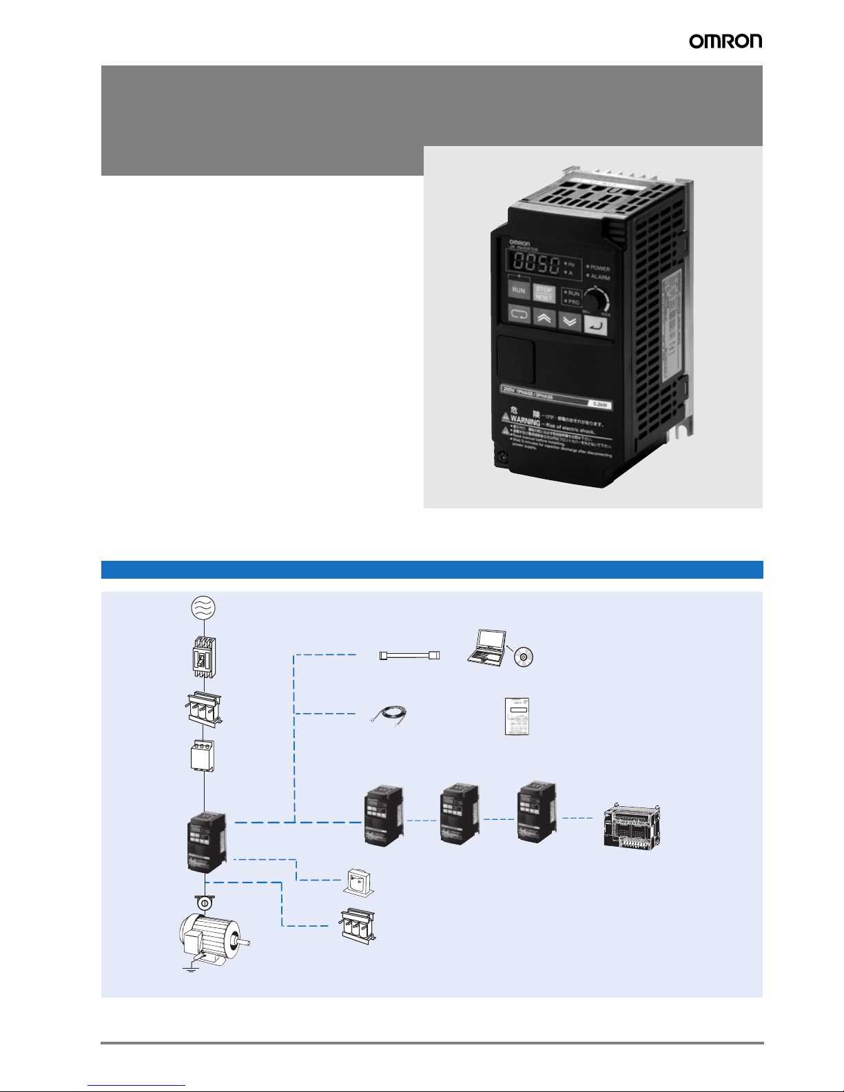
JX
Compact & Complete
• V/f controlled inverter
• Side by side mounting
• Built-in EMC filter
• Built-in RS-485 Modbus
• Overload detection function (150% during 60s)
•PID
• Micro-surge voltage suppression
• Automatic energy saving
• Emergency shut-off
• Second motor setting
• Auto carrier-frequency reduction
• PTC thermistor input
• Cooling fan switch control
• PC configuration tool: CX-Drive
• CE, UL, cUL, RoHS
Ratings
• 200 V Class single-phase 0.2 to 2.2 kW
• 200 V Class three-phase 0.2 to 7.5 kW
• 400 V Class three-phase 0.4 to 7.5 kW
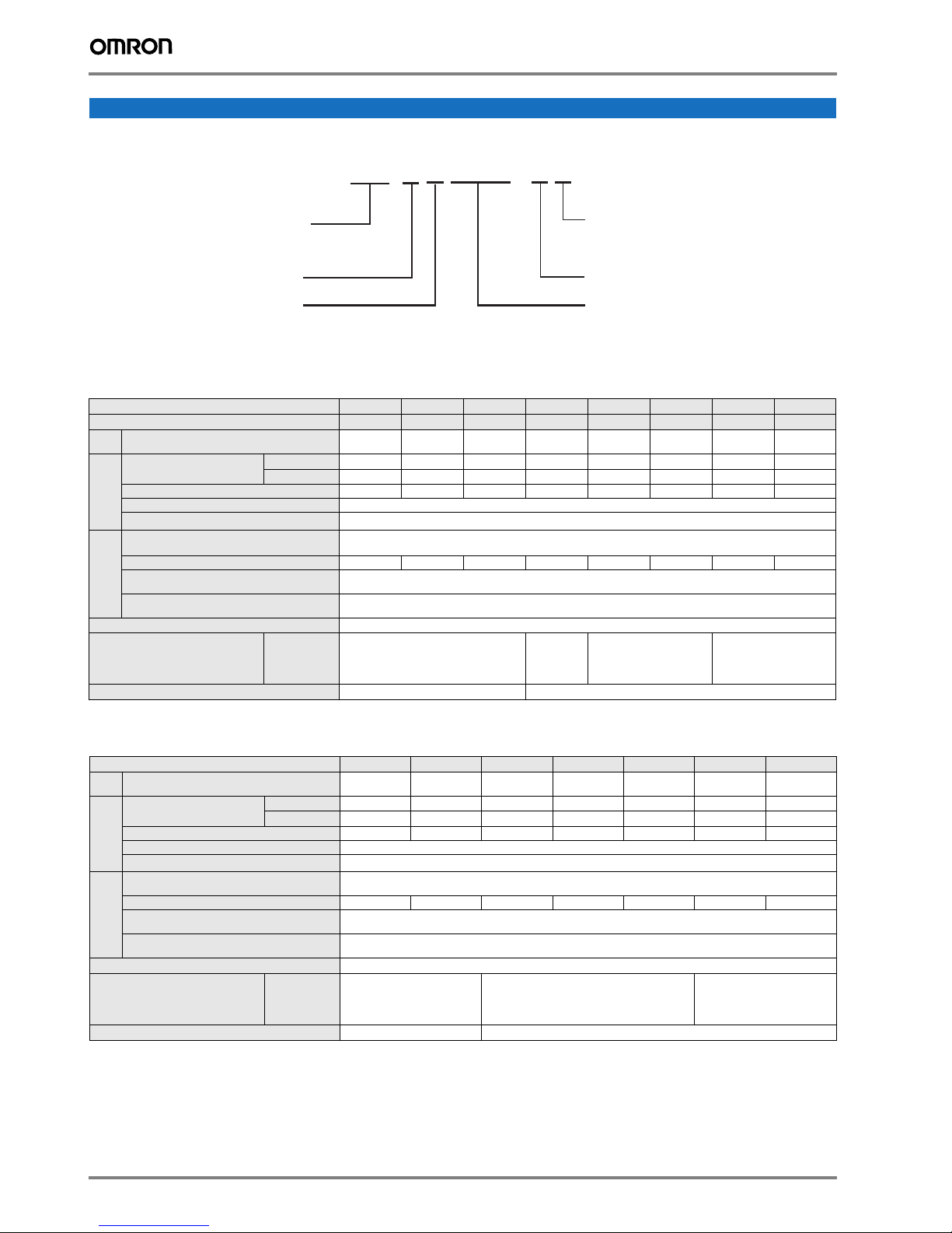
System configuration
Power
Supply
MCCB
AC Reactor
Filter
JX
Choke
Motor
Ground
*
RJ45 - USB Cable
Remote Operator
Extansion Cable
DC Reactor
Output Reactor
CX-Drive
CX-One
LCD 2 lines
Remote Operator
* Only needed for 3 phase 200V or to comply C1 on 3 phase 400V models
1JX
Specifications
JX series
A: Standard specs
JXAB002-EF
Vol tage:
B: Single-phase 200 VAC
2: Three-phase 200 VAC
4: Three-phase 400 VAC
Max. applicable motor output
002: 0,2 kW
~
075: 7,5 kW
F: Built-in EMC Filter
E: Europe standard
Type designation
200 V class
Single-phase: JX@ AB002 AB004 AB007 AB015 AB022 - - -
Motor
1
kW
Rated output current (A) 1.4 2.6 4.0 7.1 10.0 15.9 24.0 32.0
Output
Max. output voltage Proportional to input voltage: 0…240 V
Max. output frequency
characteristics
Rated input voltage
and frequency
Rated input current (A) 1.8 3.4 5.2 9.3 13.0 20.0 30.0 40.0
Allowable voltage
Power
fluctuation
supply
Allowable frequency
fluctuation
1. Based on a standard 3-Phase standard motor.
Three-phase: JX@ A2002 A2004 A2007 A2015 A2022 A2037 A2055 A2075
Applicable motor capacity 0.2 0.4 0.75 1.5 2.2 3.7 5.5 7.5
Inverter capacity kVA
Built-in filter
Braking torque
Cooling method
200 V
240 V
At short-time
deceleration
At capacitor
feedback
0.4 0.9 1.3 2.4 3.4 5.5 8.3 11.0
0.5 1.0 1.6 2.9 4.1 6.6 9.9 13.3
400 Hz
Single-phase 200…240 V 50/60 Hz
3-phase 200…240 V 50/60 Hz
-15%…+10%
+5%
EMC filter (C1 single phase)
50% for
Approx. 50%
Self cooling Forced-air-cooling
3-phase
20 to 40% for
1-phase
Approx 20% to 40% Approx 20%
400 V class
Motor
1
kW
Inverter capacity kVA
Rated output current (A) 1.5 2.5 3.8 5.5 8.6 13.0 16.0
Output
Max. output voltage Proportional to input voltage: 0…480 V
Max. output frequency
characteristics
Rated input voltage
and frequency
Rated input current (A) 2.0 3.3 5.0 7.0 11.0 16.5 20.0
Allowable voltage
fluctuation
Power
supply
Allowable frequency
fluctuation
1. Based on a standard 3-Phase standard motor.
Three-phase: JX@ A4004 A4007 A4015 A4022 A4040 A4055 A4075
Applicable motor capacity 0.4 0.75 1.5 2.2 4.0 5.5 7.5
380 V
480 V
Built-in filter
Braking torque
Cooling method
At short-time
deceleration
At capacitor
feedback
2 Frequency inverters
0.9 1.6 2.5 3.6 5.6 8.5 10.5
1.2 2.0 3.1 4.5 7.1 10.8 13.3
400 Hz
3-phase 380…480 V 50/60 Hz
-15%…+10%
+5%
EMC filter C2 class
Approx. 50% Approx. 20% to 40% Approx. 20%
Self cooling Forced-air-cooling
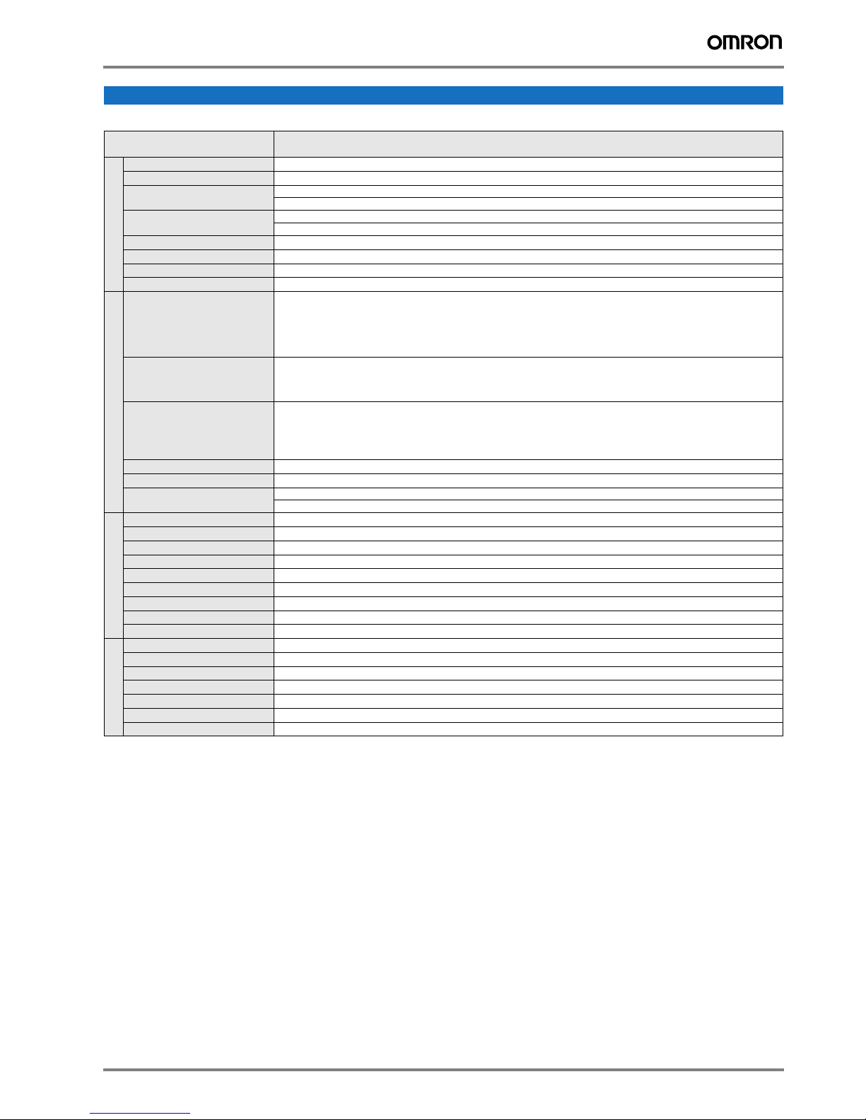
Specifications
Commom specifications
Model number
Control methods
Output frequency range
Frequency precision
Resolution of frequency set value
Resolution of output frequency
Overload capability
Control functions
Frequency set value
V/f Characteristics
Inputs signals
Output signals
Functionality
Standard functions
Analogue inputs
Accel/Decel times
Display
Motor overload protection
Instantaneous overcurrent
Overload
Overvoltage
Momentary power loss
Cooling fin overheat
Stall prevention level
Protection functions
Ground fault
Power charge indication
Degree of protection
Ambient humidity
Storage temperature
Ambient temperature
Installation
Installation height
Ambient conditions
Vibration
JX@
Specifications
Phase-to-phase sinusoidal modulation PWM (V/f)
0.5..400 Hz
Digital set value: ±0.01% of the max. frequency
Analogue set value: ±0.4% of the max. frequency (25 ±10 ºC)
Digital set value: 0.1 Hz
Analogue set value: 1/1000 of maximum frequency
0.1Hz
150% rated output current for one minute
0 to 10 VDC (10KΩ), 4 to 20mA (250Ω), frequency setting volume (selectable), RS485 Modbus
Constant/ reduced torque
FW (forward), RV (reverse), CF1 to CF4 (multi-step speed), JG (jogging), DB (external DC injection braking), SET (2nd function), 2CH (2-step acceleration/deceleration), FRS (free run), EXT (external trip), USP (USP function), SFT (soft lock), AT
(analog current input function selection), RS (reset), PTC (thermistor input), STA (3-wire startup), STP (3-wire stop), F/R (3wire forward/reverse), PID (PID selection), PIDC (PID integral reset), UP (UP of UP/DWN function), DWN (DWN of UP/DWN
function), UDC (data clear of UP/DWN function), OPE (forced OPE mode), ADD (frequency addition), F-TM (forced terminal
block), RDY (operation ready), SP-SET (special setting), EMR (emergency shutoff)
RUN (signal during operation), FA1 (frequency arrival signal 1), FA2 (frequency arrival signal 2), OL (overload warning signal), OD (PID excess deviation signal), AL (alarm signal), DC (analog input disconnection detection signal), FBV (PID FB
status output), NDc (network error), LOG (logical operation result), ODc (communication option disconnected), LOC (light
load signal)
AVR function, V/f characteristic selection, upper/lower limit, 16-step speeds, starting frequency adjustment, jogging
operation, carrier frequency adjustment, PID control, frequency jump, analog gain/bias adjustment, S-shape acceleration/
deceleration, electronic thermal characteristics/level adjustment, retry function, simplified torque boost, trip monitor, soft lock
function, frequency conversion display, USP function, 2nd control function, motor rotation speed UP/DOWN, overcurrent
suppression function
2 analogue inputs 0 to 10V (20KΩ), 4 to 20mA (250Ω)
0.01 to 3000s (line/curve selection), 2nd accel/decel setting available
Status indicator LED’s Run, Program, Power, Alarm, Power, Hz, Amps, Volume Led indicator
Digital operator: Available to monitor frequency reference, output current, output frequency
Electronic Thermal overload relay and PTC thermistor input
180% of rated current
150% for 1 minute
790V for 400V type and 395 for 200V type
Following items are selectable: Alarm, 0 Hz start, frequency output at interruption, maximum frequency
Temperature monitor and error detection
Selectable level applicable only at constant speed or during acceleration and constant speed
Detected at power-on
On when power is supplied to the control part
IP20
90% RH or less (without condensation)
-20 ºC..+65 ºC (short-term temperature during transportation)
−10°C to 50°C (Both the carrier frequency and output current need to be reduced at over 40°C.)
Indoor (no corrosive gas, dust, etc.)
Max. 1000 m
5.9 m/s2 (0.6G), 10 to 55 Hz (Complies with the test method specified in JIS C0040 (1999).)
JX 3
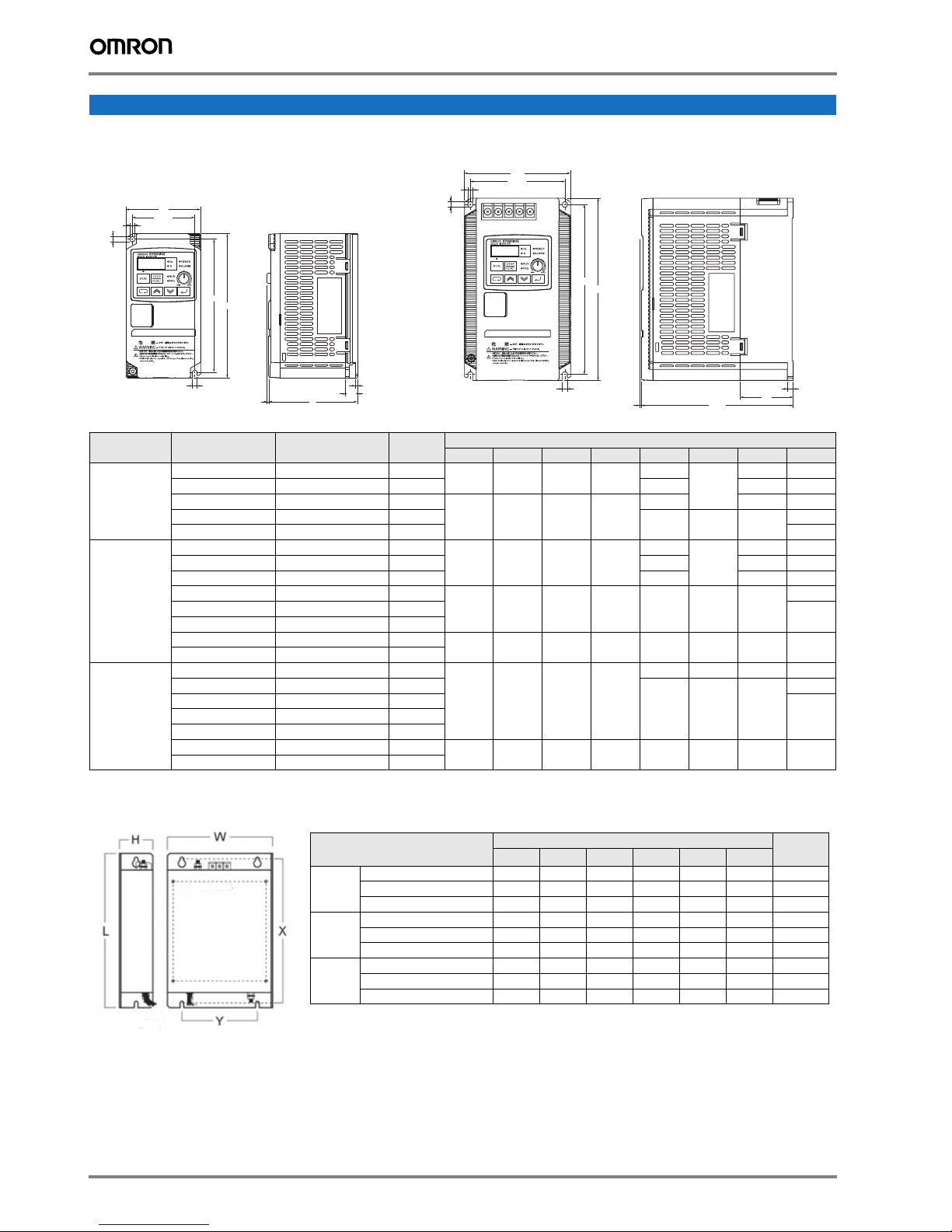
Dimensions
Figure 1
Figure 2
6
5
5
W
H1
W1
H
t1
D1
1.9
D
H1
5
H
W1
W
5
6
t1
D1
D
1.9
Rasmi model
Dimensions
Weight
KG
W H L X Y M
1x200 V
AX-FIJ1006-RE 81 40 193 183 57 M4 0.5
AX-FIJ1010-RE 112 47 226 216 88 M4 0.6
AX-FIJ1026-RE 112 47 226 216 88 M4 0.8
3x200 V
AX-FIJ2006-RE 81 50 193 183 57 M4 1.0
AX-FIJ2020-RE 112 50 226 216 88 M4 1.3
AX-FIJ2040-RE 182 55 289 279 150 M5 2.3
3x400 V
AX-FIJ3005-RE 112 45 226 216 88 M4 0.9
AX-FIJ3011-RE 112 45 226 216 88 M4 1.1
AX-FIJ3020-RE 182 45 289 279 150 M4 1.7
IP 20 type 0.2 to 7.5 kW
Voltage class
Single-phase
200 V
Max. applicable
motor output kW
Inverter model JX@ Figure
0.2 AB002 1
0.4 AB004
0.75 AB007
1.5 AB015 2
W1 H1 W H D t1 D1 Weight
1
67 143 80 155
2
98 176 110 189
2.2 AB022 2 2.4
0.2 A2002 1
0.4 A2004 1 109.5 27 0.9
67 143 80 155
0.75 A2007 1 132.5 50 1.1
Three-phase
200 V
1.5 A2015 2
2.2 A2022 2
98 176 110 189 157.5 6 55
3.7 A2037 2
5.5 A2055 2
7.5 A2075 2
164 235 180 250 167.5 1.6 77.5 4.2
0.4 A4004 2
0.75 A4007 2
Three-phase
400 V
1.5 A4015 2
4.0 A4040 2
5.5 A4055 2
7.5 A4075 2
98 176 110 189
164 235 180 250 167.5 1.6 77.5 4.2
Rasmi footprint Filters
Filter only needed by the 1-phase 200V or 3-phase 400V to comply with C1 EMC class.
Dimensions in mm
95.5
109.5 27 0.9
130.5 28 1.5
157.5 6 55
95.5
130.5 2.6 28 1.5
157.5 6 55
2.6
13 0.8
2.3
13 0.8
2.6
2.2
2.4
2.3
2.42.2 A4022 2
4 Frequency inverters
 Loading...