

Omron Junma ML-II SJDE-1ANA-OY, Junma ML-II SJDE-02ANA-OY, Junma ML-II SJDE-04ANA-OY, Junma ML-II SJDE-08ANA-OY System Configuration Manual
Page 1
SJDE-@ANA-OY
Junma ML-II servo drive
A new concept in drive simplicity
Save space, save wiring, save time
• Ultra compact drive size reduces panel space
• Tuning-less technology, no gain parameters need to
be set
• Peak torque 300% of nominal for 3 seconds
• High response, high speed, high torque and high
accuracy
• Drive version with MECHATROLINK-II port built-in
• MECHATROLINK-II simplifies wiring and reduces
installation time
• MECHATROLINK-II provides access to the system
from one point
Ratings
• 230 VAC Single-phase 100 W to 750 W (2.39 Nm)
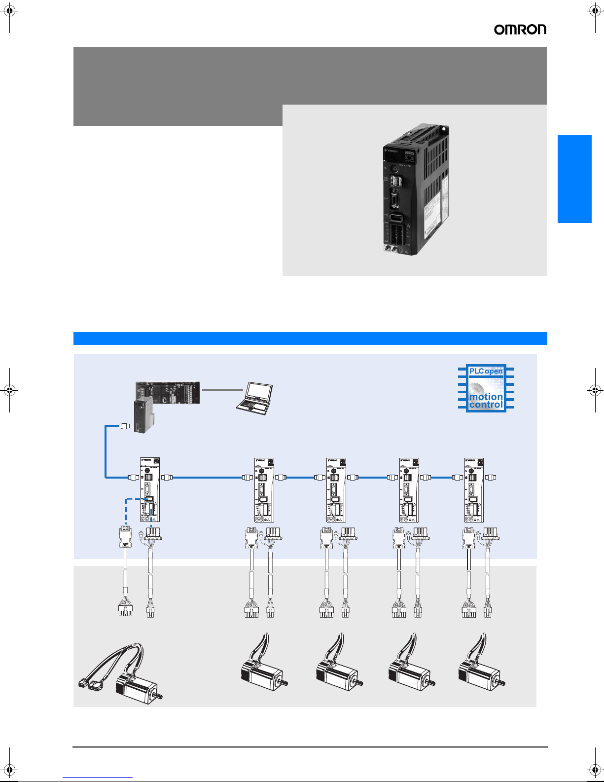
System Configuration
AC Servo systems
Junma MECHATROLINK-II Servo Drive Configuration
CJ-series PLC
CJ1 series
Position control unit
CJ1W-NCF71
Encoder
cable
Junma Servo Motor
3,000 rpm
(100-750 W)
Junma ML-II
Servo Drive
Power
cable
MECHATROLINK-II
Junma ML-II
Servo Drive
Personal computer
software: CX-One
Junma ML-II
Servo Drive
Junma ML-II
Servo Drive
Junma ML-II
Servo Drive
Terminator
165Junma ML-II servo drive
Page 2
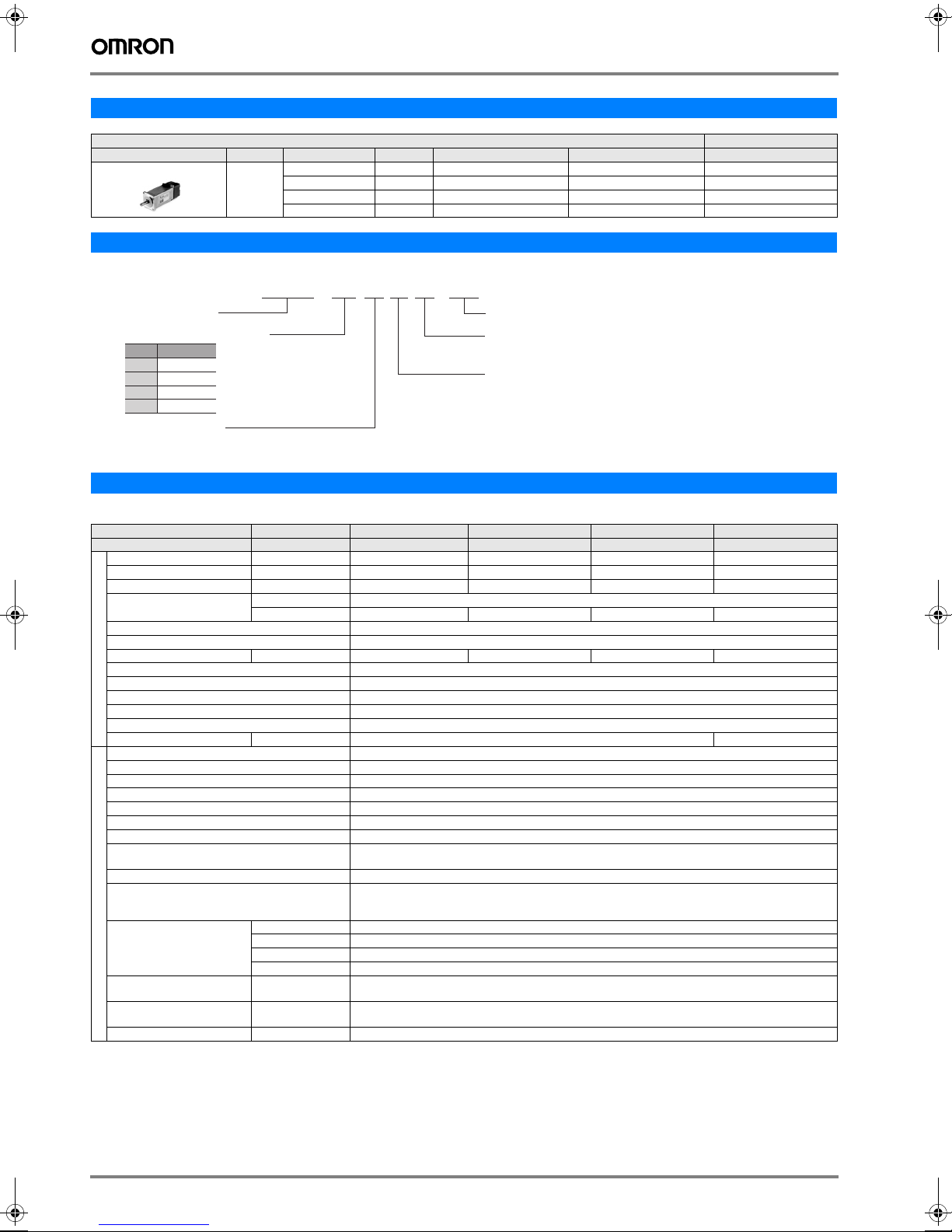
Servomotor / Servo Drive Combination
A
A
Junma Servomotor Junma servo drive
-1
SJME- (3000 min
) 200 V 0.318 Nm 100 W SJME-01AMB41-OY SJME-01AMB4C-OY SJDE-01ANA-OY
Voltage Rated Torque Capacity Model without brake Model with brake MECHATROLINK-II
0.637 Nm 200 W SJME-02AMB41-OY SJME-02AMB4C-OY SJDE-02ANA-OY
1.27 Nm 400 W SJME-04AMB41-OY SJME-04AMB4C-OY SJDE-04ANA-OY
2.39 Nm 750 W SJME-08AMB41-OY SJME-08AMB4C-OY SJDE-08ANA-OY
Servo Drive Type Designation
SJDE - 02 A N A - OY
JUNMA servo drive
pplicable servomotor capacity
Code
Output (W)
100
01
200
02
400
04
750
08
Power supply voltage
: 200 VAC
Servo Drive Specifications
Junma MECHATROLINK-II Servo Drive
Servo Drive Type SJDE- @ 01ANA-OY 02ANA-OY 04ANA-OY 08ANA-OY
Applicable servomotor SJME-@ 01A@ 02A@ 04A@ 08A@
Max. Applicable Motor capacity W 100 200 400 750
Continuous output current Arms 0.84 1.1 2.0 3.7
Max. output current Arms 2.5 3.3 6.0 11.1
Input power supply
(Main circuit and control circuit)
Control Method PWM control, sine wave current drive system
Feedback Analogue incremental encoder (13 bits incremental equivalent)
Allowable load inertia
Usage / storage temperature 0 to +55° C / -20 to 70° C
Usage / storage humidity 90%RH or less (non-condensing)
Basic specifications
Altitude 1000m or less above sea level
Vibration/shock Resistance 4.9m/s
Configuration Base mounted
Approx. mass Kg 1.0 1.4
Dynamic brake (DB) Operated at main power OFF, servo alarm, servo OFF.(OFF after motor stops; ON when motor power is off.)
Regenerative processing Optional (If the regenerated energy is too large, install a regenerative unit JUSP-RG08D)
Over-travel (OT) prevention function P_OT, N_OT
Emergency stop Emergency stop (E-STP)
LED display 4 LEDs (PWR, RDY, COM, ALM)
MECHATROLINK-II monitor MECHATROLINK-II under communication : COM LED (Light ON)
Servo ON/OFF monitor At Servo OFF : RDY LED (Light OFF), at Servo ON : RDY LED (Light Blinks)
Power supply status monitor Control / main-circuit power-supply OFF state: PWR LED (Light OFF)
Electronic gearing 0,01< A/B<100
Protection Overcurrent, overvoltage, undervoltage, overload, main circuit sensor error, board temperature error, exces-
MECHATROLINK
Built-in functions
Communication
Command input MECHATROLINK
Sequence Input signal Fixed input 5 points (fixed layout: external latch signal, zero return reduced speed signal, forward drive inhibiting signal,
Sequence Output signal Fixed output 2 points (fixed layout: servo alarm, brake interlock)
*1
Voltage Single-phase, 200 to 230 VAC, + 10 to -15% (50/60 Hz)
Capacity KVA 0.40 0.75 1.2 2.2
2
kg⋅m
Control / main-circuit power-supply ON state: PWR LED (Light ON)
sive position error overflow, overspeed, encoder signal error, overrun protection, system error, parameter er-
Comm. protocol MECHATROLINK-II
Transmission rate 10 Mbps
Transmission cycle 1ms, 1.5ms, 2ms, 3ms, 4ms
Data length 17 byte and 32 byte
communication
ror
MECHATROLINK-II commands
(For sequence, motion, data setting/reference, monitor, adjustment, and other commands)
reverse run inhibiting signal, emergency stop signal)
-4
0.6 × 10
2
(0.5G) / 19.6m/s2 (2G)
OMRON YASKAWA Motion Control BV
Design revision
A: Standard
Control Interface specification
N: MECHATROLINK-II
P: Pulse train input
-4
3.0 × 10
5.0 × 10
-4
10.0 × 10
-4
Note: *1. Value without external regeneration unit
166 AC Servo Systems
Page 3

Dimensions
Junma MECHATROLINK-II servo drives
SJDE-01, 02, 04ANA-OY (200V, 100 to 400W)
View A
5.5
150
139.5±0.5
(Mounting Pitch)
32±0.5
5
(5)
(Mounting
Pitch)
45
Detail view of installation
Cooling fan
2-M4 screw holes
Ground
Terminal
Outline
(8)
2-M4 screws
150
AIR FLOW
AIR FLOW
45
A
Model Cooling Fan
SJDE-01ANA-OY
SJDE-02ANA-OY
SJDE-04ANA-OY
CN6
CN1
CN2
CNA, CNB
Not mounted
Not mounted
Mounted
(75)
125
(16)
(6)
˚
(4.5)
AC Servo systems
(5)
19
130
Approx. mass : 1kg
Units in mm
SJDE-08ANA-OY (200V, 750W)
150
View A (Scale = 1/2)
3-M4 screw holes
5.5
150
139.5±0.5
(Mounting Pitch)
58±0.5
6
(5)
(Mounting Pitch)
Detail view of installation
70
Ground Terminal
2-M4 screws
Outline
(6)
CNA, CNB
CN6
CN1
CN2
AIR FLOW
70
A
AIR FLOW
AIR FLOW
(75)
(16)
125
(6)
(4)
˚
(5)
19
Cooling fan
180
Approx. mass : 1.4 kg
Units in mm
Junma ML-II servo drive 167
Page 4

Ordering Information
Junma MECHATROLINK-II Servo Drive Configuration
(Refer to servo motor chapter)
Junma Servo Motor
A
3,000 rpm
(100-750 W)
Junma ML-2
B
Servo Drive
Mechatrolink-II
F
cables
MECHATROLINK-II
E
Motion controller
Encoder cable
D
Power cable
C
Filter
G
H
I
Personal computer
software: CX-One
Servomotors and Servo drives
Symbol Specifications A Servomotor model B Servo drive model
Voltage Encoder and Design Rated Torque Capacity
AB
1 Phase
200 VAC
Analogue Incremental
Encoder
Straight shaft with key
Without brake 0.318 Nm 100 W SJME-01AMB41-OY SJDE-01ANA-OY
0.637 Nm 200 W SJME-02AMB41-OY SJDE-02ANA-OY
1.27 Nm 400 W SJME-04AMB41-OY SJDE-04ANA-OY
2.39 Nm 750 W SJME-08AMB41-OY SJDE-08ANA-OY
With brake 0.318 Nm 100 W SJME-01AMB4C-OY SJDE-01ANA-OY
0.637 Nm 200 W SJME-02AMB4C-OY SJDE-02ANA-OY
1.27 Nm 400 W SJME-04AMB4C-OY SJDE-04ANA-OY
2.39 Nm 750 W SJME-08AMB4C-OY SJDE-08ANA-OY
Power and encoder cables
Note: CD Refer to the Junma servo motor section for motor cables or connectors selection
MECHATROLINK-II Motion controllers
Symbol Name Model
Position Controller Unit for CJ1 PLC CJ1W-NCF71
E
Position Controller Unit for CS1 PLC CS1W-NCF71
Trajexia stand-alone motion controller, 16 axes TJ1-MC16
Trajexia stand-alone motion controller, 4 axes TJ1-MC04
MECHATROLINK-II cables
Symbol Specifications Model
MECHATROLINK-II Terminator resistor JEPMC-W6022
F
MECHATROLINK-II Cables 0.5 m JEPMC-W6003-A5
1 m JEPMC-W6003-01
3 m JEPMC-W6003-03
5 m JEPMC-W6003-05
10 m JEPMC-W6003-10
20 m JEPMC-W6003-20
30 m JEPMC-W6003-30
Cables for I/Os (for CN1)
Symbol Name Compatible units Model
G
Control
cable
Cable for servo drive I/O
signals
1 m R7A-CPZ001S
or JZSP-CHI003-01
2 m R7A-CPZ002S
or JZSP-CHI003-02
3 m JZSP-CHI003-03
Filters
Symbol Applicable servo
drive
SJDE-01ANA-OY
H
SJDE-02ANA-OY
SJDE-04ANA-OY
SJDE-08ANA-OY 9A 1.7 mA R7A-FIZN109-BE
Rated
Leakage
current
current
5A 1.7 mA 250 VAC
Rated
voltage
1- phase
Filter model
R7A-FIZN105-BE
Regenerative Unit Model (Option)
Symbol Specifications Model (Omron) Model (Yaskawa)
External regenerative unit
I
(Optional)
R88A-RG08UA JUSP-RG08D
Connectors
Specification Model (Omron) Model (Yaskawa)
Control I/O connector (for CN1) R7A-CNA01R JZSP-CHI9-1
Power input connector (for CNB).
(Included in drive the box)
R7A-CNZ01P JZSP-CHG9-1
Computer Software
Specifications Model
Configuration and monitoring software tool via ML2
(CX-Drive version 1.3 or higher)
Complete Omron software package including CX-Drive
(CX-One 2.0 or higher)
CX-DRIVE
CX-ONE
ALL DIMENSIONS SHOWN ARE IN MILLIMETERS.
To convert millimeters into inches, multiply by 0.03937. To convert grams into ounces, multiply by 0.03527.
Cat. No. I70E-EN-01
In the interest of product improvement, specifications are subject to change without notice.
168 AC Servo Systems
 Loading...