

Page 1

Cat.No. Z127–E1–1
R/W Heads and
SRAM Data Carriers
V600 RFID System
OPERATION MANUAL
Page 2
V600 RFID System
R/W Heads and SRAM Data Carriers
Operation Manual
Produced August 1998
Page 3

!
!
!
v
Notice:
OMRON products are manufactured for use according to proper procedures by a qualified operator
and only for the purposes described in this manual.
The following conventions are used to indicate and classify precautions in this manual. Always heed
the information provided with them. Failure to heed precautions can result in injury to people or damage to property.
DANGER Indicates an imminently hazardous situation which, if not avoided, will result in death or
serious injury.
WARNING Indicates a potentially hazardous situation which, if not avoided, could result in death or
serious injury.
Caution Indicates a potentially hazardous situation which, if not avoided, may result in minor or
moderate injury, or property damage.
Product Application
You must allow sufficient leeway against product ratings and functionality, and provide safety measures, such as fail-safe measures, whenever applying the products described in this manual in any of
the following situations. Always consult with your OMRON representative whenever applying the
products in any of these situations.
• Applications under any conditions or any environments not described in this
manual.
• Applications for nuclear power control, railways, aviation, automobiles, furnaces, medical equipment, amusement equipment, safety equipment, etc.
• Applications that can affect human life or property or that particularly require
safety.
Visual Aids
The following headings appear in the left column of the manual to help you locate different types of
information.
Note Indicates information of particular interest for efficient and convenient operation
of the product.
1, 2, 3... 1. Indicates lists of one sort or another, such as procedures, checklists, etc.
OMRON, 1998
All rights reserved. No part of this publication may be reproduced, stored in a retrieval system, or transmitted, in any
form, or by any means, mechanical, electronic, photocopying, recording, or otherwise, without the prior written permission of OMRON.
No patent liability is assumed with respect to the use of the information contained herein. Moreover, because OMRON is
constantly striving to improve its high-quality products, the information contained in this manual is subject to change
without notice. Every precaution has been taken in the preparation of this manual. Nevertheless, OMRON assumes no
responsibility for errors or omissions. Neither is any liability assumed for damages resulting from the use of the information contained in this publication.
Page 4

TABLE OF CONTENTS
vii
SECTION 1
Features and System Configuration 1. . . . . . . . . . . . . . . . .
1-1 Features 2. . . . . . . . . . . . . . . . . . . . . . . . . . . . . . . . . . . . . . . . . . . . . . . . . . . . . . . . . . . . . . .
1-2 System Configuration 3. . . . . . . . . . . . . . . . . . . . . . . . . . . . . . . . . . . . . . . . . . . . . . . . . . . . .
SECTION 2
Specifications 5. . . . . . . . . . . . . . . . . . . . . . . . . . . . . . . . . . .
2-1 R/W Heads 6. . . . . . . . . . . . . . . . . . . . . . . . . . . . . . . . . . . . . . . . . . . . . . . . . . . . . . . . . . . . .
2-2 Data Carriers 8. . . . . . . . . . . . . . . . . . . . . . . . . . . . . . . . . . . . . . . . . . . . . . . . . . . . . . . . . . .
2-3 Data Carrier Battery Service Life 12. . . . . . . . . . . . . . . . . . . . . . . . . . . . . . . . . . . . . . . . . . .
SECTION 3
Communications Specifications 15. . . . . . . . . . . . . . . . . . . .
3-1 Transmission Range 16. . . . . . . . . . . . . . . . . . . . . . . . . . . . . . . . . . . . . . . . . . . . . . . . . . . . . .
3-2 Transmission Time 17. . . . . . . . . . . . . . . . . . . . . . . . . . . . . . . . . . . . . . . . . . . . . . . . . . . . . . .
3-3 Data Carrier Speed 19. . . . . . . . . . . . . . . . . . . . . . . . . . . . . . . . . . . . . . . . . . . . . . . . . . . . . . .
SECTION 4
Installation 21. . . . . . . . . . . . . . . . . . . . . . . . . . . . . . . . . . . . .
4-1 R/W Head Installation 22. . . . . . . . . . . . . . . . . . . . . . . . . . . . . . . . . . . . . . . . . . . . . . . . . . . .
4-2 Data Carrier Installation 26. . . . . . . . . . . . . . . . . . . . . . . . . . . . . . . . . . . . . . . . . . . . . . . . . . .
SECTION 5
Chemical Resistance 31. . . . . . . . . . . . . . . . . . . . . . . . . . . . .
Appendices
A Accessories (Sold Separately) 33. . . . . . . . . . . . . . . . . . . . . . . . . . . . . . . . . . . . . . . . . . . . . . . . .
B Discontinued Models and Replacements 35. . . . . . . . . . . . . . . . . . . . . . . . . . . . . . . . . . . . . . . . .
C Other Series 49. . . . . . . . . . . . . . . . . . . . . . . . . . . . . . . . . . . . . . . . . . . . . . . . . . . . . . . . . . . . . . .
Revision History 51. . . . . . . . . . . . . . . . . . . . . . . . . . . . . . . . .
Page 5

ix
About this Manual:
This manual describes the installation and operation of the V600-series Read/Write Heads and batterypowered SRAM Data Carriers, and includes the sections described below.
Please read this manual carefully and be sure you understand the information provided before attempting
to install and operate the Read/Write Heads and Data Carriers. Keep this manual in a convenient location
where it can continue to be used for reference and guidance.
Section 1 provides general information on features and system configuration.
Section 2 provides specifications for the Read/Write Heads and Data Carriers.
Section 3 provides communications specifications.
Section 4 explains how to install the Read/Write Heads and Data Carriers.
Section 5 provides information on specific chemicals that affect the Read/Write Heads and Data Carriers.
Appendix A provides information on accessories that can be purchased separately.
Appendix B provides information on discontinued models and their replacements.
Appendix C provides information on particular models to be used in England.
WARNING Failure to read and understand the information provided in this manual may result in
personal injury or death, damage to the product, or product failure. Please read each
section in its entirety and be sure you understand the information provided in the section
and related sections before attempting any of the procedures or operations given.
!
Page 6

1
SECTION 1
Features and System Configuration
This section provides a general introduction to the V600 RFID System, including the V600-series Read/Write (R/W) Heads
and Data Carriers. The V600 RFID System utilizes non-contact data transfer in which data is transmitted electromagnetically
without physical contact between the devices.
1-1 Features 2. . . . . . . . . . . . . . . . . . . . . . . . . . . . . . . . . . . . . . . . . . . . . . . . . . . . . . . . . . . . . . . .
1-2 System Configuration 3. . . . . . . . . . . . . . . . . . . . . . . . . . . . . . . . . . . . . . . . . . . . . . . . . . . . .
Page 7
1-1SectionFeatures
2
1-1 Features
The V600 RFID System offers powerful support to the automation of large-scale
distributed control systems and multi-model small-scale production systems by
means of contactless data communication.
Data is transmitted between the Data Carrier (DC) and Read/Write (R/W) Head
electromagnetically in both directions, without physical contact between the two
devices.
SRAM (static random access memory) is used for th e D C’ s memory. There is no
limit to the number of times that the memory can be accessed for reading or writing data. The memory is powered by a long-life lithium battery.
A 16-bit CRC (Cyclic Redundancy Check) has been added to detect data transmission errors in both directions between the ID Controller and R/W Head, and
the R/W Head and DC. This feature also helps to ensure superior transmission
reliability even in environments where noise tends to occur.
The DCs have an 8K-byte memory. In addition to essential identification data,
information on models and test results can be entered on-site.
The battery will last eight years in temperatures ranging from –25°C to 70°C
(–18°F to 158°F).
The projected battery service life can be easily checked by means of a command
from the ID Controller, which simplifies battery maintenance.
The R/W Head and DC offer superior resistance to environmental factors such
as vibration, oil, water, and so on.
Contactless Data
Transfer
SRAM Memory
CRC Error Detection
8K-byte Memory
Long Battery Life
Battery Status Checking
Superior Durability and
High Reliability
Page 8
1-2SectionSystem Configuration
3
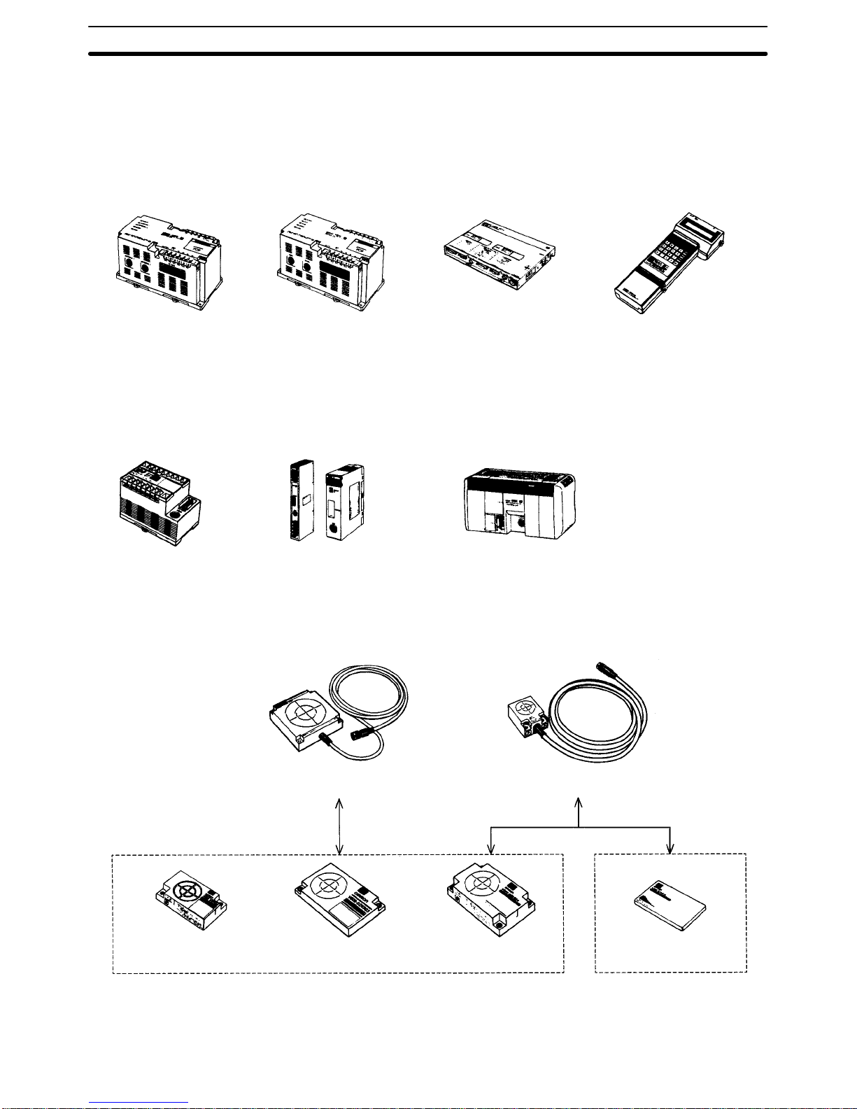
1-2 System Configuration
A V600 RFID System is made up of ID Controllers, R/W Heads, and DCs. A system can be assembled to suit almost any situation with different arrangements of
these components.
ID Controllers and ID Sensor Units
V600-CA1A/CA2A V600-CA8A/CA9A V600-CF1A V600-CB-S
100 to 240 VAC
Host: RS-232C/RS-422
100 to 240 VAC
Host: Parallel PNP/NPN
100 to 240 VAC
Host: RS-232C
Hand-held Model
V600-CD1D-V2 C500-IDS01-V2
C200H-IDS01-V1
IDSC-C1DR-A
IDSC-C1DT-A
24 VDC
Host: RS-232C
PLC, ID Sensor Units ID Controllers
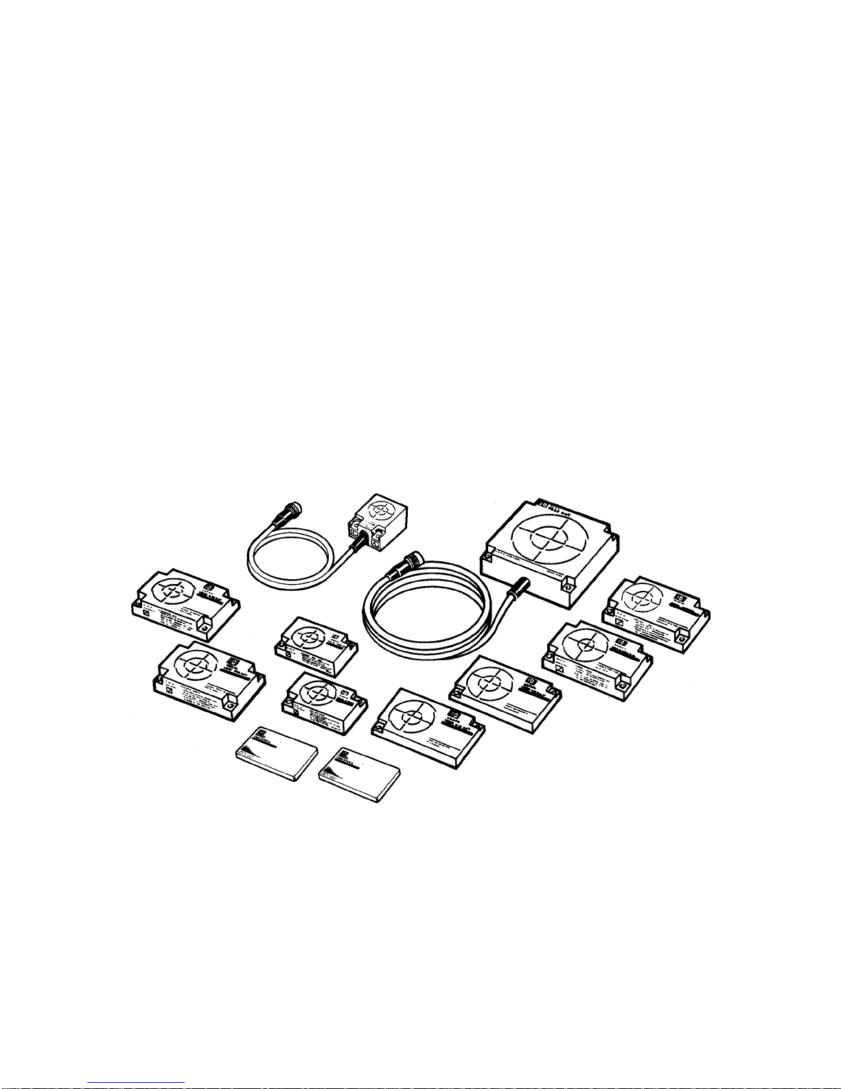
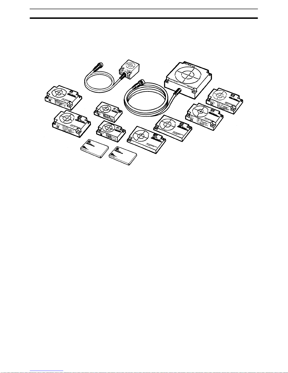
R/W Heads and Data Carriers
V600-H07 V600-H11
V600-D8KR12 V600-D8KR13 V600-D8KR04 V600-D2KR16
Note Refer to Appendix B for details on the availability of V600-H12 and
V600-D8KR11.
Page 9

5
SECTION 2
Specifications
This section provides Read/Write (R/W) Head and Data Carrier (DC) specifications.
2-1 R/W Heads 6. . . . . . . . . . . . . . . . . . . . . . . . . . . . . . . . . . . . . . . . . . . . . . . . . . . . . . . . . . . . .
2-1-1 Specifications and Outer Dimensions 6. . . . . . . . . . . . . . . . . . . . . . . . . . . . . . . . . .
2-2 Data Carriers 8. . . . . . . . . . . . . . . . . . . . . . . . . . . . . . . . . . . . . . . . . . . . . . . . . . . . . . . . . . . .
2-2-1 Specifications and Outer Dimensions 8. . . . . . . . . . . . . . . . . . . . . . . . . . . . . . . . . .
2-2-2 Memory Map 10. . . . . . . . . . . . . . . . . . . . . . . . . . . . . . . . . . . . . . . . . . . . . . . . . . . .
2-2-3 Write Protect Function 10. . . . . . . . . . . . . . . . . . . . . . . . . . . . . . . . . . . . . . . . . . . . .
2-3 Data Carrier Battery Service Life 12. . . . . . . . . . . . . . . . . . . . . . . . . . . . . . . . . . . . . . . . . . . .
2-3-1 Battery Service Life Factors 12. . . . . . . . . . . . . . . . . . . . . . . . . . . . . . . . . . . . . . . . .
2-3-2 Battery Service Life Expectancy Check 14. . . . . . . . . . . . . . . . . . . . . . . . . . . . . . . .
Page 10
2-1SectionR/W Heads
6
2-1 R/W Heads
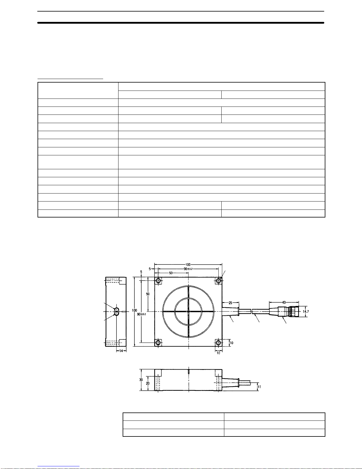
2-1-1 Specifications and Outer Dimensions
V600-H07/V600-H11
Item
Model
V600-H07 V600-H11
Operating frequency 530 kHz
Operating temperature –25°C to 70°C –10°C to 60°C
Storage temperature –40°C to 85°C –25°C to 75°C
Operating humidity 35% to 95% RH
Insulation resistance 50 MΩ min. between cable terminals and case (at 500 VDC)
Dielectric strength 1,000 VAC 50/60 Hz for 1 minute between cable terminals and case.
Degree of protection (See note.) Meets or exceeds IEC60529 IP67 and JEM IP67G standards.
Vibration resistance 10 to 500 Hz, 1.0 mm in each direction; acceleration: 150 m/s2 (about 15 G); one
sweep in each of three axis directions, three sweeps in 11 minutes
Shock resistance 500 m/s2 (about 50 G) three times each in X, Y, Z directions, total 18 times
Error detection 16-bit CRC (Cyclic Redundancy Check) is used in both directions of transmission.
LED indicators Power supply: green; communications: orange
Cable length Standard lengths of 0.5, 2, 5, and 10 m.
Max. cable length 30.5 m 50.5 m
Weight (approximate) 1 kg (with 10 m cable) 650 g (with 10 m cable)
Note The connectors are not waterproof.
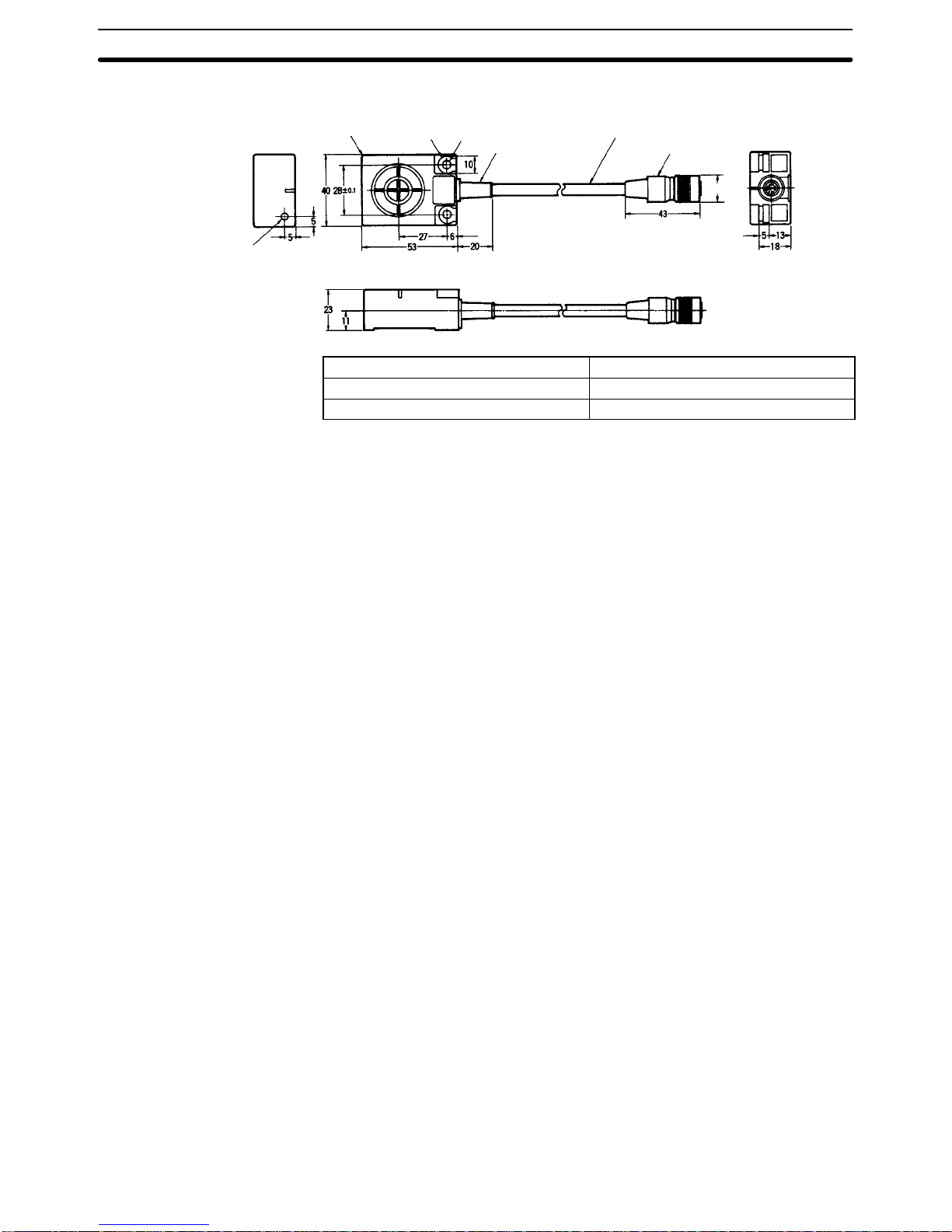
V600-H07
Power indicator (LED)
Operation indicator (LED)
Mounting holes (four, 4.5 dia.)
Bushing
Vinyl-insulated
round cord (6 dia)
Connector
Case material ABS resin
Fill resin Epoxy resin
Cable PVC (oil-resistant)
Page 11
2-1SectionR/W Heads
7
V600-H11
LED indicators
Power supply (green)
Communications (orange)
Mounting holes
(Two, 4.5 dia.)
Bushing
Connector
Vinyl-insulated
round cord (6 dia)
Four, R1
Two, R5
14.7 dia.
Case material ABS resin
Fill resin Epoxy resin
Cable PVC (oil-resistant)
Page 12
2-2SectionData Carriers
8
2-2 Data Carriers
2-2-1 Specifications and Outer Dimensions
V600-D8KR12/13/04
Item
Model
V600-D8KR12 V600-D8KR13 V600-D8KR04
Memory capacity 8K bytes
Memory type SRAM (static random access memory)
Battery service life Refer to the graphs in 2-3 Data Carrier Battery Service Life.
Number of data read/write
conversions
No limit (up to the extent of the battery service life)
Error detection 16-bit CRC error detection is used in both directions of transmission.
Operating temperature Data retention: –40°C to 70°C; read/write: –25°C to 70°C
Storage temperature –40°C to 70°C
Operating humidity 35% to 95% RH
Degree of protection Meets or exceeds IEC60529 IP67 standards and JEM IP67G standards.
Vibration resistance 10 to 500 Hz, 1.0 mm in each direction; acceleration: 150 m/s2 (about 15 G); one sweep
in each of three axis directions, three sweeps in 11 minutes
Shock resistance 1,000 m/s2 (about 100 G) three times each in X, Y, Z directions, total 18 times
Weight (approximate) 70 g 70 g 160 g
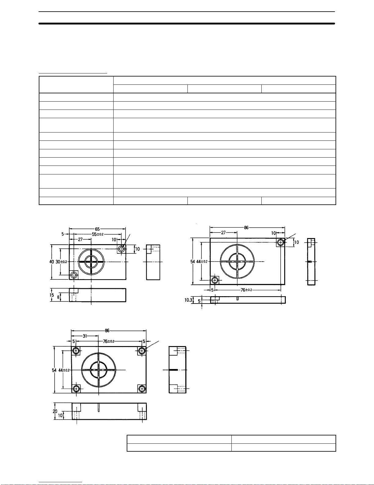
V600-D8KR12 V600-D8KR13
V600-D8KR04
Mounting holes
(Two, 4.5 dia.)
Mounting holes
(Two, 4.5 dia.)
Mounting holes
(Four, 4.5 dia.)
Case material ABS resin
Fill resin Epoxy resin
Page 13
!
!
2-2SectionData Carriers
9
WARNING The SRAM-type Data Carrier has a built-in lithium battery which can combust or
explode if mishandled. Do not disassemble the Data Carrier, or subject it to high
pressure or high temperatures (of 100°C or more), or dispose of it by
incineration.
V600-D2KR16
Item V600-D2KR16
Memory capacity 2K bytes
Memory type SRAM (static random access memory)
Battery service life (See note 1.) 2 years (replaceable battery)
Number of data read/write
conversions
No limit (unrelated to battery service life)
Error detection 16-bit CRC error detection is used in both
directions of transmission.
Operating temperature Data retention: –15°C to 70°C; read/write: 0°C
to 50°C
Storage temperature –15°C to 70°C
Operating humidity 35% to 85% RH
Degree of protection (See note 2.) IEC60529 IP50 standards
Vibration resistance 10 to 150 Hz, 1.5 mm in each direction;
acceleration: 100 m/s
2
(about 10 G); for 30 min.
each in X, Y, Z directions.
Shock resistance 300 m/s2 (about 30 G) three times each in X, Y,
Z directions, total 18 times
Weight (approximate) 15 g
Note 1. This is the battery service life when the battery is used in an environment
with an ambient temperature below 25°C. For the relationship between temperature and battery service life, refer to 2-3 Data Carrier Battery Service
Life.
2. When the accessory battery replacement cover seal is in place.
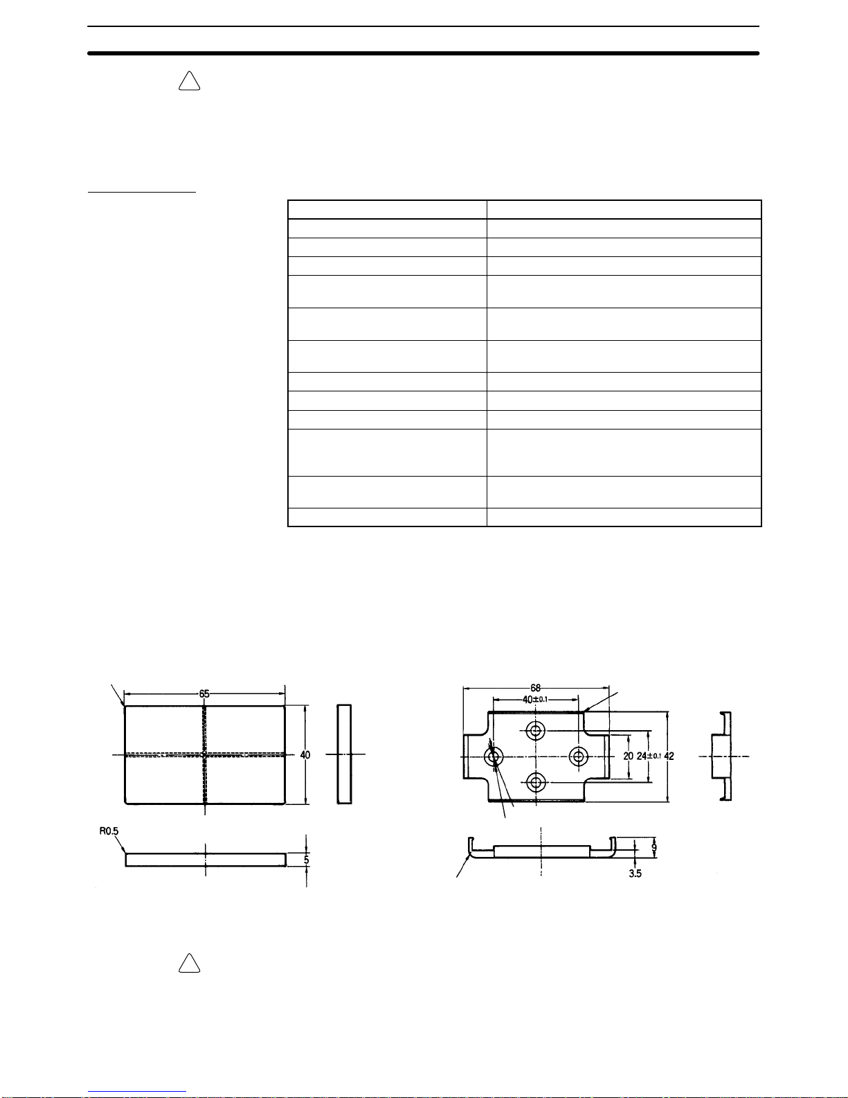
V600-D2KR16 Special-purpose Holder (V600-A81)
Four, R1.5
Eight, R0.5
(Four, 3.5 dia.)
(Four, 5.5 dia.)
Two, R2.5
Case material: ABS resin
WARNING The SRAM-type Data Carrier has a built-in lithium battery which can combust or
explode if mishandled. Do not disassemble the Data Carrier, or subject it to high
pressure or high temperatures (of 100°C or more), or dispose of it by
incineration.
Page 14
2-2SectionData Carriers
10
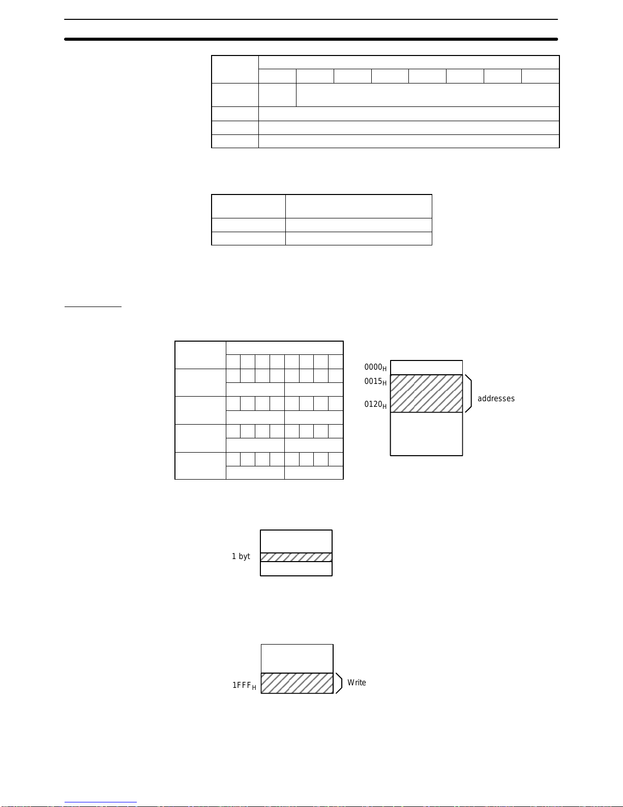
2-2-2 Memory Map
The Data Carrier (DC) has a memory area of up to 8K bytes. Each address of the
memory area specifies one byte. A single byte of data can be written to one
address.
0000
H
0001
H
0002
H
to
0005
H
0006
H
to
00FF
H
0100
H
to
01FF
H
to
0700
H
to
1FFF
H
to
to
to
to
Address
Data
Leftmost digit Rightmost digit
1 byte
8K
Production date area
Write protect setting area
Production Date Area (Written by Maker)
Address Bit
7 6 5 4 3 2 1 0
0000
H
Month (10s digit) Month (1s digit)
0001
H
Year (10s digit) Year (1s digit)
Note 1. Address 0000 contains the month of production (March→“03,” Octo-
ber→“10”).
2. Address 0001 contains the lower two digits of the year (1997→“97”).
3. This area is read only.
The memory is SRAM, so there is no limit on the number of times that data can
be read or overwritten.
The memory capacity is 8 KB, and the available addresses are 0000H to 1FFFH.
The memory contents are preserved by a long-life lithium battery.
2-2-3 Write Protect Function
The write protect function protects important data stored in the memory of the
Data Carrier, such as product number and model, from being overwritten inadvertently. With this function, the data in a specified memory area can be protected. It is recommended that important data be write-protected as follows:
Setting the Write Protect Function
The write protect function is set in the four bytes of addresses 0002H through
0005H of the Data Carrier’s memory. The status of the leftmost bit of address
0002H determines whether or not the write protect function is in effect.
Page 15
2-2SectionData Carriers
11
Address Bit
7 6 5 4 3 2 1 0
0002
H
YES/NOLeftmost two digits of beginning address
0003
H
Rightmost two digits of beginning address
0004
H
Leftmost two digits of ending address
0005
H
Rightmost two digits of ending address
The region specified by the beginning and ending addresses will be protected
when the write protect control bit (leftmost bit of address 0002H) is ON, as shown
in the following table.
Leftmost bit of
0002
H
Write Protect Function
ON Data is write-protected.
OFF Data is not write-protected.
Area that can be set:
Beginning address: 0006H to 1FFF
H
Ending address: 0006H to 1FFF
H
Examples
1, 2, 3... 1. The following settings would write-protect addresses 0015H through 0120
H
(i.e., the beginning address to the ending addresses):
Address Bit
7 6 5 4 3 2 1 0
0002
H
1 0 0 0 0 0 0 0
8 0
0003
H
0 0 0 1 0 1 0 1
1 5
0004
H
0 0 0 0 0 0 0 1
0 1
0005
H
0 0 1 0 0 0 0 0
2 0
2. To write-protect only 1 byte, set the same address as the start and ending
addresses (beginning address = ending address).
1 byte Write-protected address
Address
3. If the ending address exceeds the last address of the Data Carrier memory
(ending address > 1FFFH), the addresses up to 1FFFH will be write-protected:.
0000
H
1FFF
H
Write-protected addresses
Address
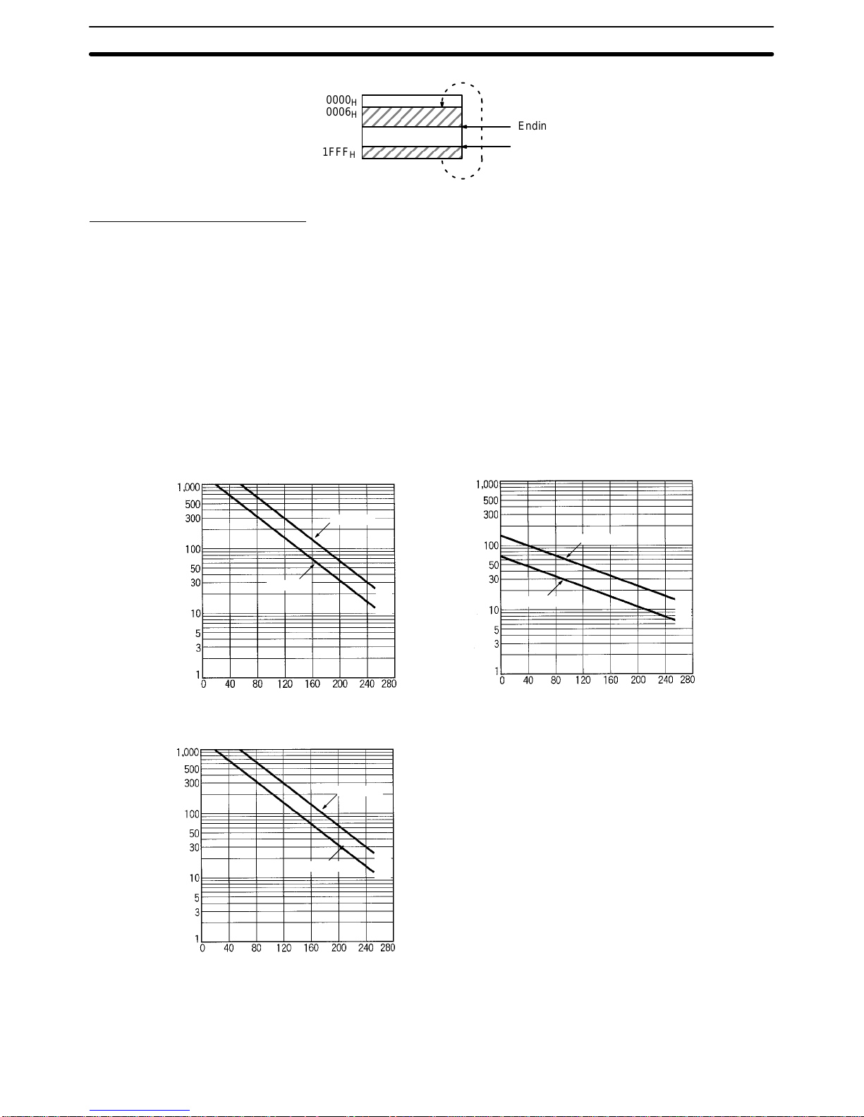
4. If the beginning address is greater than the ending address (beginning
address > ending address), the write-protected area will wrap through
0006H, so that addresses from 0006H through the ending address,and from
the beginning address through 1FFFH will be write-protected.
When Executing the
Write Protect Function
Write-protected
addresses
0000
H
0015
H
0120
H
1FFF
H
Address
to
Page 16
2-3SectionData Carrier Battery Service Life
12
0000
H
0006
H
1FFF
H
Ending address
Beginning address
Address
Canceling Write Protection
To cancel write protection, turn OFF the leftmost bit of address 0002H. The write
protection will be cancelled, and the beginning and ending addresses that are
set for 0002H to 0005H will be ignored.
2-3 Data Carrier Battery Service Life
2-3-1 Battery Service Life Factors
The Data Carrier has a built-in lithium battery that provides power. The service
life of the battery depends on the number and size of data transmissions. The
graphs below show the relationship between daily number and size of transmissions and battery service life. (The illustrations shown here are representative
examples.)
Number of bytes/transmission
Daily number of transmissions x 100
V600-D8KR12
8 years
5 years
Number of bytes/transmission
Daily number of transmissions x 100
Number of bytes/transmission
Daily number of transmissions x 100
V600-D8KR13
V600-D8KR04
8 years
5 years
8 years
5 years
The preceding graphs show the lowest possible lifetimes for DCs in the temperature range –10°C to 55°C (14°F to 131°F). Normally, batteries will last longer at
lower ambient temperatures.
Page 17
2-3SectionData Carrier Battery Service Life
13
With a V600-D8KR04 DC at 5 5°C (131°F), for example, 200 bytes of data can be
accessed 3,000 times a day for 8 years or 6,500 times a day for 5 years.
With a V600-D8KR12 DC at 55°C (131°F), 40 bytes of data can be accessed
2,000 times a day for 8 years or 4,500 times a day for 5 years.
The battery used for the V600-D2KR16 has a service life of 2 years at an ambient temperature of 25°C, regardless of the number of access times or R/W
bytes.
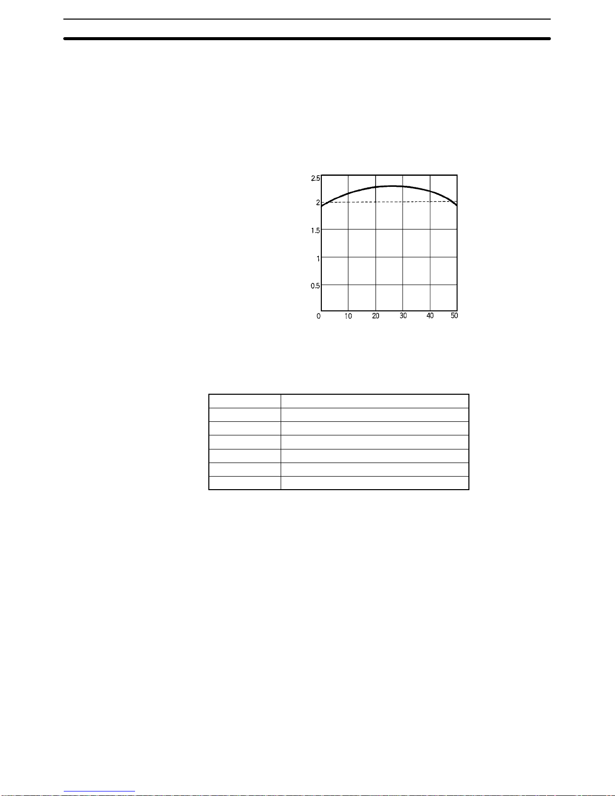
Battery Service Life vs. Temperature
Ambient temperature (°C)
Battery life (years)
The above graph shows the relationship between the service life of a built-in battery and ambient temperature (after the insulation sheet is removed). The table
below shows the life expectancy of a battery that is stored separately (without
being installed in the DC).
Temperature Battery consumption rate (%) per year
20 1
30 2
40 4
50 8
60 16
70 32
If the DC is kept at a temperature of 70°C without removing the insulation sheet,
the battery will last for 1.36 years (2 years x (1 – 0.32)). Furthermore, if the DC is
kept for one year at a temperature of 70°C without removing the insulation sheet,
the battery will last for an additional period of approximately 1.4 years if used at
an ambient temperature of 25°C. The life of the battery will be shorter if used at
an ambient temperature of 0° or 50°C.
Note 1. The data in the V600-D2KR16 will be lost at the time of battery replacement.
Be sure to make a backup of the data before replacing the battery.
2. After replacing the battery, be sure to affix the battery cover seal. IP50 is not
guaranteed if the battery cover seal is not affixed.
V600-D2KR16
Page 18

2-3SectionData Carrier Battery Service Life
14
2-3-2 Battery Service Life Expectancy Check
Checking Whether the Battery is Low
Models With Built-in Battery (Except V600-D2KR16)
1, 2, 3... 1. Data Carrier battery checks are not performed automatically, only during
times of special access.
When a battery check is performed, a small current is passed through the
DC’s internal circuitry. Too much power would be consumed if a battery
check was performed automatically every time DC memory was accessed.
Incorporate a routine once-a-day check when creating the system program.
2. Access for checking whether the battery is low is only enabled when the two
bytes of data from address 0000H to 0001H are read.
Use one of the following commands to check the battery status. (The CR at
the end of each command means carriage return.)
a) Read command: RD H/A 1 0000 02*CR
b) Auto Read command: AR H/A 1 0000 02*CR
c) Polling Auto Read command: PR H/A 1 0000 02*CR
3. If the end code of the response is 00, the battery is operating normally. If the
end code is 7B, the battery is low. The following are responses to Read and
Auto Read commands sent to a DC with a good battery:
RD 0 0 0 9 9 7 *
AR 0 0 0 9 9 7 *
Normal end code
Read data
Production date: Sept., 1997
The following are responses to Read and Auto Read commands sent to a
DC with a low battery:
RD 7 B 0 9 9 7 *
AR 7 B 0 9 9 7 *
Low battery end code
Read data
Production date: Sept., 1997
Note With the V600-D2KR16 (replaceable-battery model), read/write commands are
executed without regard to addresses.
Service Life of Data Carriers After the Battery-low Code is Generated
Under ordinary operating conditions the DC can be used for about one month
after a low battery end code is received. However, it is recommended that the DC
be replaced with a new one as soon as possible.
The V600-D2KR16 (replaceable-battery model) can be used for approximately
two weeks under normal operating conditions, but it is recommended that the
battery be replaced with a new one as soon as possible.
Note The DC (except for the V600-D2KR16, SRAM memory model) contains a thionyl
chloride-type lithium battery. One characteristic of this type of battery is its tendency to develop a higher internal resistance when it is not used. If the battery
isn’t used for several months, the internal resistance can increase enough to
cause a low battery response, even if the battery is good.
Consequently, after several months of disuse it is recommended to transmit data
to/from the DC for about 10 minutes to “warm up” the battery and decrease its
internal resistance. This operation will have almost no effect on the useful life of
the battery.
Page 19

15
SECTION 3
Communications Specifications
This section provides specifications for communications.
3-1 Transmission Range 16. . . . . . . . . . . . . . . . . . . . . . . . . . . . . . . . . . . . . . . . . . . . . . . . . . . . . .
3-1-1 Transmission Range Specifications (Certified Performance) 16. . . . . . . . . . . . . . . .
3-1-2 Transmission Areas 17. . . . . . . . . . . . . . . . . . . . . . . . . . . . . . . . . . . . . . . . . . . . . . .
3-2 Transmission Time 17. . . . . . . . . . . . . . . . . . . . . . . . . . . . . . . . . . . . . . . . . . . . . . . . . . . . . . .
3-3 Data Carrier Speed 19. . . . . . . . . . . . . . . . . . . . . . . . . . . . . . . . . . . . . . . . . . . . . . . . . . . . . . .
Page 20
3-1SectionTransmission Range
16
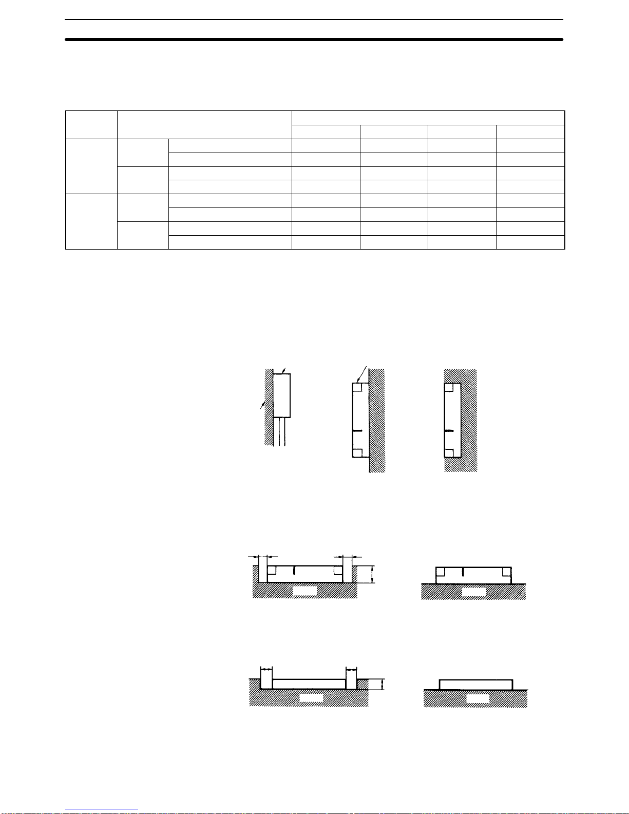
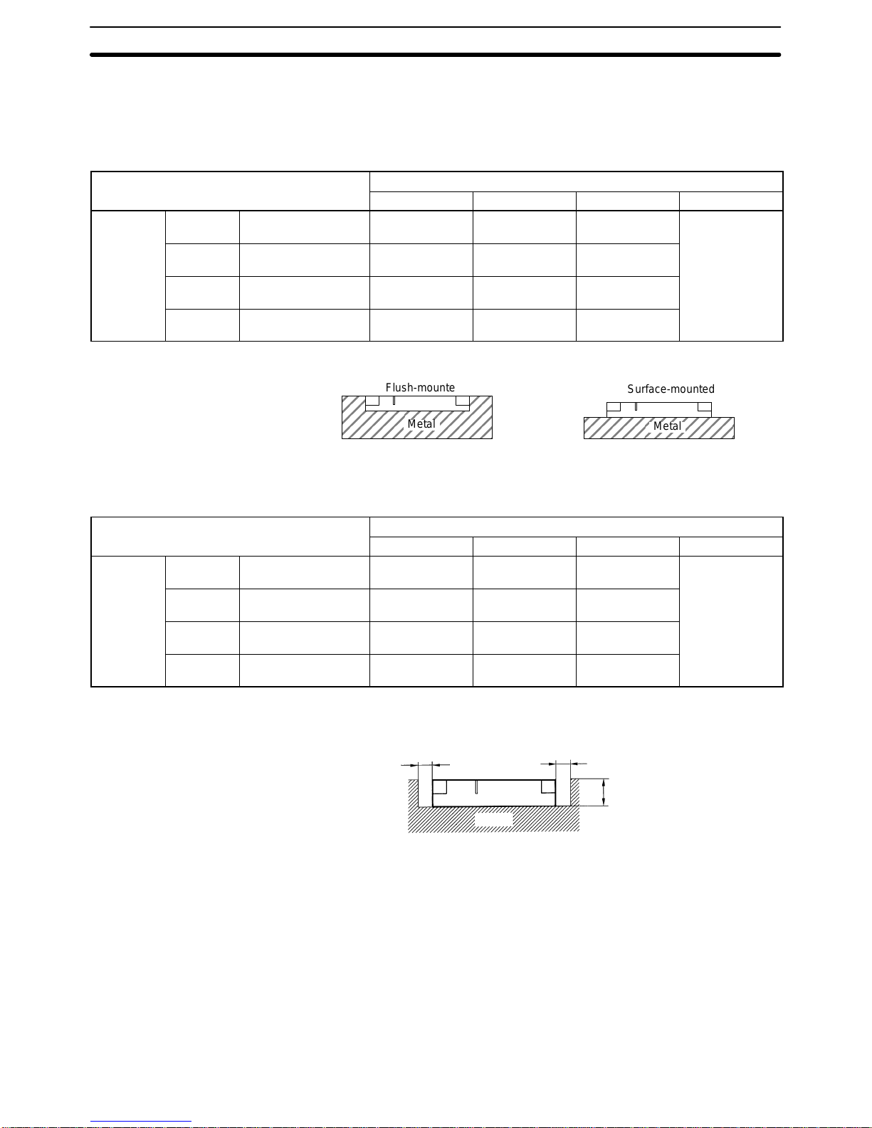
3-1 Transmission Range
3-1-1 Transmission Range Specifications (Certified Performance)
R/W Head Setting conditions
Transmission range (unit: mm, axis slip: ±10 mm)
V600-D8KR12 V600-D8KR13 V600-D8KR04 V600-D2KR16
V600-H07 Stationary
Flush-mounted within metal 10 to 50 10 to 30 See page 28. --Surface-mounted on metal 10 to 60 10 to 35 10 to 100 ---
Moving
Flush-mounted within metal 25 to 50 20 to 30 See page 28. --Surface-mounted on metal 25 to 60 20 to 35 50 to 100 ---
V600-H11 Stationary
Flush-mounted within metal 5 to 40 10 to 30 See page 28. 2 to 15
Surface-mounted on metal 5 to 45 10 to 30 10 to 65 2 to 15
Moving
Flush-mounted within metal 25 to 40 15 to 30 See page 28. 6 to 15
Surface-mounted on metal 25 to 45 15 to 30 30 to 65 10 to 15
Note 1. These specifications are the certified performance when taking into consid-
eration variations in ambient temperatures and products.
2. The read range and the write range are the same.
3. The Data Carrier and Read/Write Head installation conditions are as follows:
1) V600-D8KR12, V600-D8KR13 Data Carriers
Read/Write Head
Steel
Data carrier
Metal Metal
Surface-mounted on metal Flush-mounted within metal
For flush-mounting within metal, the read/write distance changes depending on
distance x from the metal.
Metal
Surface-mountedFlush-mounted
x mm x mm
Flush-mounted within metal
20 mm max.
Metal
Surface-mounted on metal
3) V600-D2KR16 Data Carriers
Metal
Data carrierData carrier
10 mm min. 10 mm min.
Flush-mounted within metal
5 mm max.
(see note)
Metal
Surface-mounted on metal
For details regarding R/W Head and DC installation, refer to Section 4 Installa-
tion.
2) V600-D8KR04 Data
Carriers
Page 21
3-2SectionTransmission Time
17
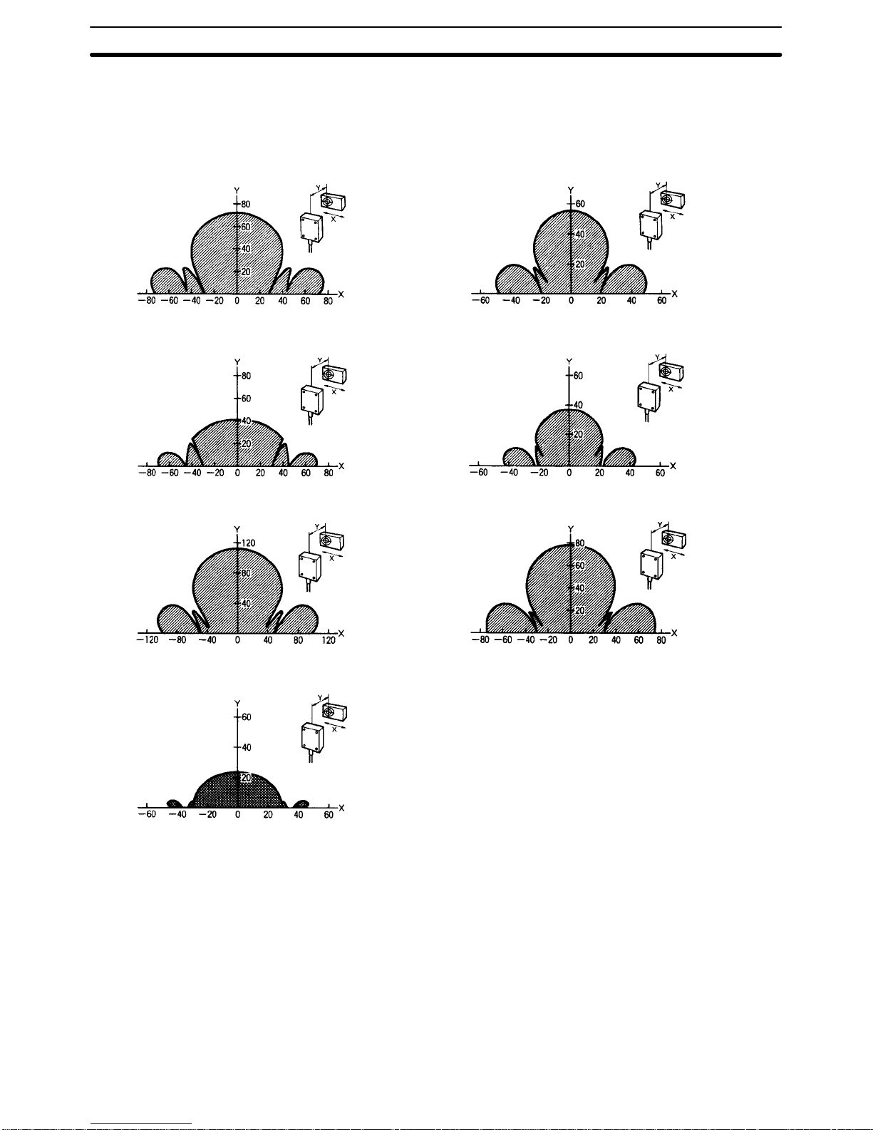
3-1-2 Transmission Areas
The following diagrams show representative examples of the communications
areas. All measurement units are shown in mm.
V600-D8KR12 and V600-H07 V600-D8KR12 and V600-H11
V600-D8KR13 and V600-H07
V600-D8KR13 and V600-H11
V600-D8KR04 and V600-H07 V600-D8KR04 and V600-H11
V600-D2KR16 and V600-H11
Note The mounting method is surface-mounted on
metal in all cases.
3-2 Transmission Time
Transmission times are the same for all models of R/W Heads and DCs covered
in this manual, although transmission times are different for DCs that contain
batteries. The term “transmission time” is used to indicate both the turn-around
time (TA T ) and the lower level transmission time between the R/W Head and DC.
The TAT is the total time required from the transmission of a command from a
host device (such as a host computer) until the reception of a response at the
host device.
The lower-level transmission time is the time required for transmission of data
between the R/W Head and DC.
Transmission Time
Page 22

3-2SectionTransmission Time
18
The following diagram shows the TAT and lower-level transmission time for the
READ command.
RDH1. * ↵. . . . . .
RD001122 * ↵. . .
Lower-level
transmission time
Turn-around time (TAT)
The following diagrams show the TAT and lower-level transmission time for
V600-CA1A, V600-CA2A, V600-CD1D-V2, and V600-CF1A Serial Interface ID
Controllers. (The TAT for Parallel Interface ID Controllers and ID Sensor Units
varies with the host’s software.)
(Auto) read
(Auto) write
Number of bytes processed
Turn-around time (ms)
Calculation Method (Reference) (Unit: ms)
Read/Write TAT
Read T = 2.9N + 69.8
Write T = 5.3N + 105.6
N: Number of bytes processed
Note 1. The value given for the TAT data assumes that the communications settings
for the V600-CA1A ID Controller are as follows:
Baud rate: 9600 bps; data length: 8 bits; stop bits: 1; parity: odd.
2. The number of bytes is the number for ASCII code. (For details, refer to the
RFID System Operation Manual (Z83).
Transmission Time With the Data Carrier (Reference)
Number of bytes processed
Lower-level transmission time (ms)
(Auto) read
(Auto) write
TAT (Reference)
Page 23

3-3SectionData Carrier Speed
19
Calculation Method (Reference) (Unit: ms)
Read/Write Lower-level transmission time
Read T = 1.8N + 48.4
Write T = 4.2N + 86.5
N: Number of bytes processed
3-3 Data Carrier Speed
The number of bytes that can be processed using the Auto Read and Auto Write
commands depends on the speed of the DC. The relationship between the number of bytes and DC speed in m/minute can be determined from the following
equation.
Max. DC Speed =
Distance travelled in the transmission range (m)
Lower-level transmission time (min)
• The “distance travelled in the transmission range (m)” is the maximum width o f
the transmission range (in the X direction). Refer to the diagrams in 3-1 Trans-
mission Range.
• The “lower-level transmission time (min)” is the time required for transmission
between the DC and the R/W Head. For details regarding this calculation, refer
to 3-2 Transmission Time.
In this example diagram, the V600-D8KR04 and V600-H07 are combined and
four bytes are read.
110 mm
This diagram shows the following:
Distance travelled in transmission range, Y (transmission distance) = 110 mm
Lower-level transmission time, T = 1.8 x 4 + 48.4 = 55.6 ms.
Accordingly, the DC speed in this case will be as follows:
Max. DC Speed =
Distance travelled in the transmission range (m)
Lower-level transmission time (min)
=
110 (mm)
55.6 (ms)
= 118.7 m/min
Note 1. The distance travelled in the transmission time will vary depending on the
read/write distance and the shaft slippage. Refer to the diagrams in 3-1
T ransmission Range.
2. The DC speed is the standard value. Before using the equipment, run a test
to determine the speed under the actual operating conditions.
3. The DC speed data above do not take into account possible transmission
errors in host or lower-level communications.
4. When the V600-CA8A/CA9A is used, the speed will vary depending on the
software at the host device.
Calculation Example
Page 24

21
SECTION 4
Installation
This section describes the recommended installation methods for the R/W Heads and Data Carriers (DCs), and provides
details on the battery’s service life expectancy and methods to check the battery’s condition.
4-1 R/W Head Installation 22. . . . . . . . . . . . . . . . . . . . . . . . . . . . . . . . . . . . . . . . . . . . . . . . . . . .
4-1-1 Installation Method 22. . . . . . . . . . . . . . . . . . . . . . . . . . . . . . . . . . . . . . . . . . . . . . . .
4-1-2 Effect of Surrounding Metals 23. . . . . . . . . . . . . . . . . . . . . . . . . . . . . . . . . . . . . . . .
4-1-3 Interference between R/W Heads 24. . . . . . . . . . . . . . . . . . . . . . . . . . . . . . . . . . . . .
4-1-4 Interference with Proximity Sensors 25. . . . . . . . . . . . . . . . . . . . . . . . . . . . . . . . . .
4-2 Data Carrier Installation 26. . . . . . . . . . . . . . . . . . . . . . . . . . . . . . . . . . . . . . . . . . . . . . . . . . .
Page 25

4-1SectionR/W Head Installation
22
4-1 R/W Head Installation
4-1-1 Installation Method
V600-H07 R/W Head
Use M4 screws and spring washers (in four places) for R/W Head installation.
Tighten the screws to a torque of 0.7 to 1.2 NSm (approximately 7 to 12 kgfScm).
There are no restrictions on the mounting direction or the direction of access to
the DC, but if the R/W Head is to be installed near a device such as a conveyance
belt, make sure there is no danger of the R/W Head being accidentally struck.
90±0.2
100
90±0.2
100
Four, M4
mounting holes
Mounting Bracket Dimensions (V600-H07 Only)
90±0.1
90±0.1
100±0.2
100±0.2
Four, C1 corners
Four, 4.5
+0.5
–0
mm-dia. holes
Page 26

!
4-1SectionR/W Head Installation
23
Note A mounting bracket is provided with the V600-H07. It is not necessary to use this
bracket if a metal mounting plate larger than the 100×100 mm “footprint” of the
R/W Head is used for installation.
V600-H07
Mounting plate
Mounting bracket
(included with V600-H07)
Caution Be sure to ground the mounting surface of the R/W Head if it is metal.
V600-H11 R/W Head
(1) Front Panel Mounting
Two, M4
mounting holes
Coil center
Insert the nuts that are included with the R/W Head into the locations marked “A.”
Nut
Coil center
Two, 4.5 dia.
4-1-2 Effect of Surrounding Metals
In addition to surface mounting, it is also possible to flush-mount the V600-H07
within a metal casing to protect it from being struck by other objects. To prevent
malfunctioning, allow at least 50 mm between the sides of the R/W Head and the
metal casing, and do not mount the R/W Head below the metal surface. If the
2) Rear Panel Mounting
V600-H07 R/W Head
Page 27

4-1SectionR/W Head Installation
24
gap between sides of the R/W Head and the metal casing is less than 50 mm, the
read/write transmission range will be greatly diminished.
50 mm min.
50 mm min.
50 mm min.
50 mm
11 mm
radius min.
50 mm min.
30 mm max.
Metal casing
min.
Metal casing
(Unit: mm)
Note 1. Do not bend the R/W Head’s cable into a curve tighter than 11 mm in radius.
2. The read/write transmission range will be reduced significantly if the R/W
Head is installed closer than 50 mm to metal surfaces.
In addition to surface mounting, it is also possible to flush-mount the V600-H11
within a metal casing to protect it from being struck by other objects. To prevent
malfunctioning, allow at least 30 mm between the sides of the R/W Head and the
metal casing, and do not mount the R/W Head below the metal surface. If the
gap between sides of the R/W Head and the metal casing is less than 30 mm, the
read/write transmission range will be greatly diminished.
30 mm min.
30 mm min.
30 mm
11 mm
radius min.
50 mm min.
23 mm max.
Metal casing
min.
(Unit: mm)
Metal casing
30 mm min.
Note 1. Do not bend the R/W Head’s cable in a curve tighter than 1 1 mm in radius.
2. The read/write transmission range will be reduced significantly if the R/W
Head is installed closer than 30 mm to metal surfaces.
4-1-3 Interference between R/W Heads
When using two or more R/W Heads, be sure to allow enough space between
the R/W Heads to avoid errors caused by mutual interference. The diagrams
below show the minimum spacing required.
When facing each other, V600-H07 R/W Heads should be installed at least 650
mm apart if RD/WT commands are used, and 900 mm apart if auto commands
are used.
V600-H11 R/W Head
V600-H07 R/W Head
Page 28

4-1SectionR/W Head Installation
25
When facing the same direction, V600-H07 R/W Heads should be installed at
least 550 mm apart (center to center) if RD/WT commands are used, and1,200
mm apart (center to center) if auto commands are used.
650 mm min.
(900 mm min.)
550 mm min.
(1,200 mm min.)
When facing each other, V600-H07 R/W Heads should be installed at least 200
mm apart regardless of whether RD/WT commands or auto commands are
used.
When facing the same direction, V600-H07 R/W Heads should be installed at
least 200 mm apart regardless of whether RD/WT commands or auto commands are used.
200 mm min.
200 mm min.
Note For applications in which no two R/W Heads transmit or receive data at the same
time (i.e., in which the R/W Heads read and write independently), there is no risk
of mutual interference and the R/W Heads can be installed in proximity. Transmission and reception in this case refer to the R/W Heads oscillating after receiving commands.
4-1-4 Interference with Proximity Sensors
V600-series R/W Heads use electromagnetic linking (frequency: 530 kHz), so, if
they are installed near sensors (such as proximity sensors) with an oscillation
frequency of 400 to 600 kHz, it may cause the sensors to malfunction. Before
installing R/W Heads, and when selecting sensors, be sure to conduct tests to
make sure that there will be no interference.
As shown in the following diagrams, a V600-H07 R/W Head should be at least
400 mm from a proximity sensor when the two are facing the same direction or
V600-H11 R/W Head
V600-H07 R/W Head
Page 29

4-2SectionData Carrier Installation
26
perpendicular. When the two are facing each other, they should be at least 300
mm apart.
400 mm min.
Proximity
sensor
Proximity
sensor
400 mm min.
300 mm min.
Proximity
sensor
V600-H07
As shown in the following diagrams, a V600-H11 R/W Head should be at least
100 mm from a proximity sensor regardless of whether the two are parallel, perpendicular, or facing each other.
100 mm min.
Proximity
sensor
Proximity
sensor
100 mm min.
100 mm min.
Proximity
sensor
V600-H11
4-2 Data Carrier Installation
V600-D8KR12/KR13/KR04 Data Carriers
Use M4 screws and spring washers for DC installation. Tighten the screws to a
torque of 0.7 to 1.2 NSm (approximately 7 to 12 kgfScm).
V600-H11 R/W Head
Installation Method
Page 30

4-2SectionData Carrier Installation
27
There are no restrictions on the mounting direction or the direction with respect
to the R/W Heads.
V600-D8KR12 V600-D8KR13
V600-D8KR04
Two, M4
Two, M4
Four, M4
Mounting in Metal Casing
V600-D8KR12
V600-D8KR13
Surface-mounted
Flush-mounted
Flush-mounted
Surface-mounted
Metal
Metal
Metal
Metal
15 mm max.
10 mm max.
The V600-D8KR12 and V600-D8KR13 DCs can be either surface-mounted or
flush-mounted. When flush-mounted in metal, the top of the DC must not be
lower than the surface of the metal casing.
V600-D8KR04
Metal
Surface-mounted
Metal
Flush-mounted
20 mm max.
x (mm) x (mm)
Flush-mounted in metal casing Surface-mounted on metal
Page 31

4-2SectionData Carrier Installation
28
When the V600-D8KR04 is flush-mounted in a metal casing, the transmission
range varies according to the width of the gap (x) between the metal and the DC,
as shown in the following graphs.
When Combined With V600-H07 When Combined With V600-H11
(over 100 mm)
Transmission range (mm)
Gap between R/W Head and metal (x)
(Shaft slip: ±0 mm)
R/W Head DC
(over 100 mm)
Transmission range (mm)
(Shaft slip: ±0 mm)
R/W Head DC
Gap between R/W Head and metal (x)
The transmission range will be reduced if the R/W Head does not face the DC
directly when data is transmitted. Try to keep any misalignment below 10°, as
shown in the following diagram.
DC
Read/Write Head
DC
Read/Write Head
This angle should
not exceed 10°.
θ
Correct Incorrect
V600-D2KR16 Data Carriers
Use a special-purpose holder (purchased separately) for installation. First
secure the holder with flat countersunk-head screws in at least two places, and
tighten the screws to a torque of 0.3 to 0.5 NSm (approximately 3 to 5 kgfScm).
Then insert the DC into this holder by hand.
Be sure to attach the battery cover seal to the back of the DC. If this seal is not
affixed, the IP protective structure standards will not be satisfied.
(Four, 3.5 dia.)
(Four, 5.5 dia.)
Effect of Misalignment
Installation Method
Page 32

4-2SectionData Carrier Installation
29
The V600-D2KR16 can be either surface-mounted or flush-mounted in a metal
casing. If mounted as shown in the following diagrams, there will be no effect on
the transmission range.
Metal casing
Surface-mounted
Flush-mounted
5 mm max.
(See note.)
10 mm min. 10 mm min.
Data carrier
Flush-mounted in metal casing
Metal casing
Surface-mounted on metal
Data carrier
Note When the special-purpose holder is used, this becomes 9 mm max.
The transmission range will be reduced if the R/W Head does not face the DC
directly when data is transmitted. Try to keep any misalignment below 10°, as
shown in the following diagram.
DC
Read/Write Head
DC
Read/Write Head
This angle should
not exceed 10°.
θ
Correct Incorrect
Mounting in a Metal
Casing
Effect of Misalignment
Page 33

31
SECTION 5
Chemical Resistance
This section shows the chemicals that affect R/W Heads and Data Carriers.
Page 34
!
Section 5Chemical Resistance
32
R/W Heads and Data Carriers are constructed using both ABS resin and epoxy
resin. Referring to the following charts, be sure to use only those chemicals that
have no effect on the ABS or epoxy resins and avoid using those chemicals that
do have an effect.
Applications requiring explosion-proof capability are not possible.
Chemicals that Cause Warping, Cracking, Etc.
Affecting ABS Affecting Epoxy
Trichlene, acetone, xylene, toluene, gasoline, creosol,
methylene chloride, phenol, cyclohexane, aqua, regia,
chromic acid, sulfuric acid (90% RT), methyl ethyl ketone,
aniline, nitrobenzene, monochlorobenzene, pyridine, nitric
acid (60% RT), formic acid (80% RT)
Aqua regia, chromic acid, sulfuric acid (90% RT), nitric
acid (60% RT), ammonia solution, acetone, methylene
chloride, phenol, trichlene
Chemicals that May Cause Discoloring, Swelling, Etc.
Affecting ABS Affecting Epoxy
Hydrochloric acid, alcohol, Freon, sodium hydroxide,
hydrogen peroxide, benzine, sulfuric acid (10% RT), nitric
acid (10% RT), phosphoric acid (85% RT), ammonia
solution
Sulfuric acid (10% RT), nitric acid (10% RT), hydrochloric
acid (30% RT), acetic acid (50% RT), calcium hydroxide,
benzine, creosol, alcohol, cyclohexane, toluene, xylene,
benzine, grease
Chemicals that Have No Effect
ABS Epoxy
Ammonia, kerosine, mineral oil, developer, Yushiroken
S50, Chemi-Cool Z, Velocity No. 3, Yushiroken EEE-30Y,
petroleum, grease acetate, calcium hydroxide, phosphoric
acid (30% RT), hydrochloric acid (10% RT), potassium
hydroxide
Ammonia, hydrochloric acid (10% RT), potassium
hydroxide, petroleum, gasoline, Yushiroken S50,
Chemi-Cool Z, Velocity No. 3, Yushiroken EEE-30Y
Caution The test results listed were obtained at room temperature (approximately 23°C).
Some of the chemicals listed as having no e ffect may cause problems at higher
or lower temperatures.
Page 35
33
Appendix A
Accessories (Sold Separately)
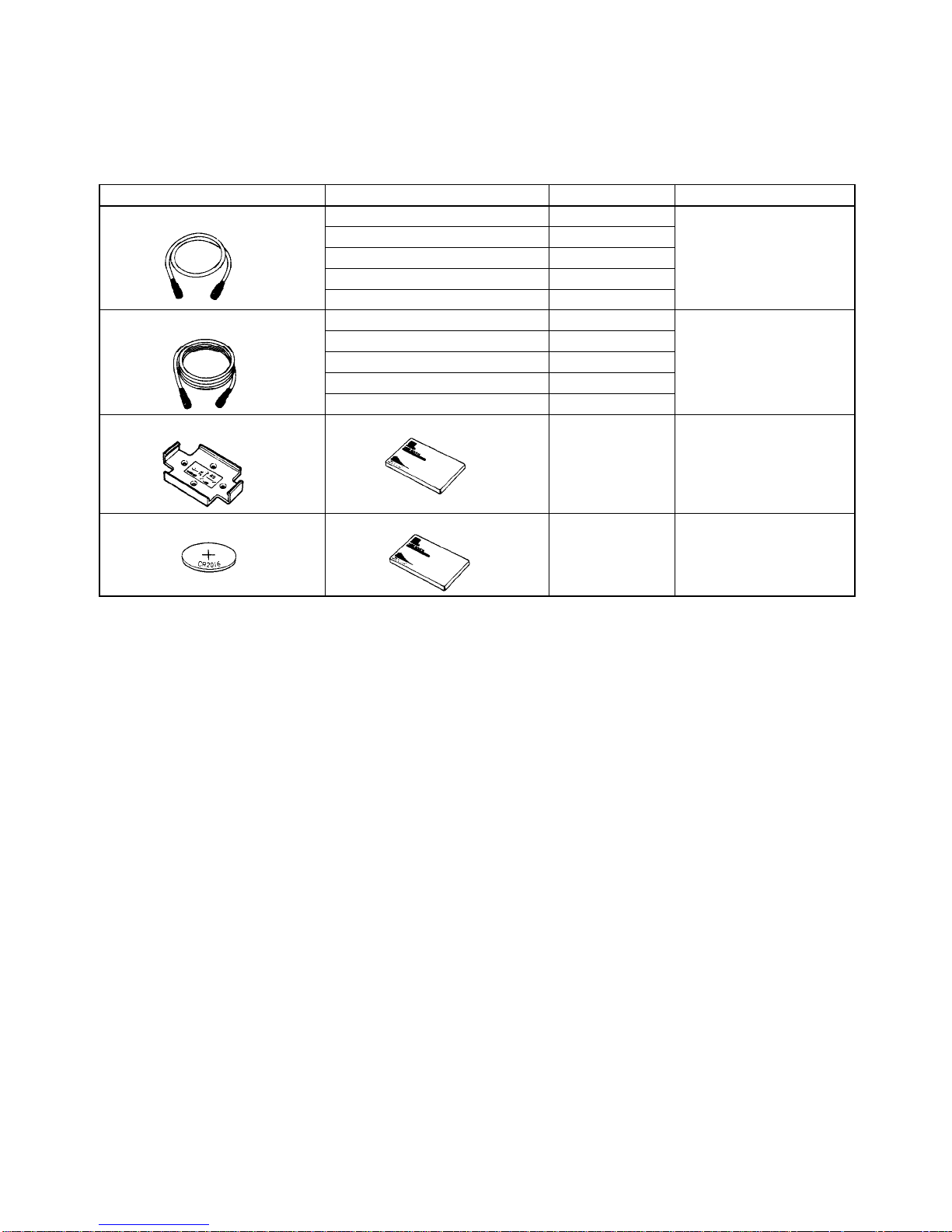
Item Specification Model Remarks
Extension cable for R/W Heads
3 m V600-A45
The connectors are not
5 m V600-A44
waterproof.
10 m V600-A40
20 m V600-A41
30 m V600-A42
Extension cable for R/W Heads
3 m V600-A56
The connectors are not
5 m V600-A55
waterproof.
10 m V600-A50
20 m V600-A51
30 m V600-A52
Special-purpose holder For V600-D2KR16 only V600-A81 Secured with M3 flat
countersunk-head screws
(in at least two places).
Lithium battery (CR2016) For V600-D2KR16 only V600-A82 CR2016 commercially
available, with battery
cover tool.
Page 36

35
Appendix B
Discontinued Models and Replacements
Discontinued Models
V600-H6
V600-D2KR01, V600-D8KR01
V600-D2KR02. V600-D8KR02
V600-D2KR03, V600-D8KR03
Replacement Models
V600-H12, V600-H11
V600-D8KR11
V600-D8KR12
V600-D8KR13
OMRON appreciates your continued patronage. In October, 1994, it was announced that production of the
500-kHz-frequency wireless transmission models in the V600-series RFID System would be discontinued in
March of 1996. The following information is an update on the models that will be discontinued and the models that
will replace them.
Background
• In 1988, OMRON began development and production of the V600-series RFID System in response to customer
requests, and provided a line of products in this series.
• Systems such as the V600-series RFID System which use electromagnetic linking are required to be in compliance with laws regulating radio wave transmissions. Within Japan there is no particular problem for ID makers
as long as they can demonstrate that they satisfy the prescribed values in the radio wave regulations. And products used in the United States, for example, must receive certification from the Federal Communications Commission (FCC). Accordingly, OMRON received FCC certification for the V600 Series in 1989.
• Subsequently, however, the FCC rules were revised, and models using a frequency of 500 kHz for wireless
transmission between read/write heads and data carriers could not be newly sold or delivered (including installation) in the United States as of June 23, 1994.
OMRON’s Response
• In response to the above problem, OMRON changed the frequency for all new wireless-transmission products in
the V600 Series from 500 kHz to 530 kHz, and in 1991 received formal certification from the FCC. Since then, all
subsequent models in this series have also been developed for 530-kHz specifications.
• Taking into consideration the maintenance and support of existing 500-kHz models from June 23, 1994,
onwards, the models that OMRON introduced in April, 1994, are completely interchangeable with the earlier
models in all respects (such as shape, installation, etc.) except for transmission frequency.
Advantages for Customers
Standardizing all of the V600-series models to 530 kHz offers the following advantages to customers.
• There is no longer any need to distinguish between models exported to the United States, and other countries,
and models marketed in Japan. This simplifies the processes of model selection and system design, and
reduces the chances of accidentally ordering the wrong models.
• This change makes it easier to combine various read/write heads and data carriers, thereby expanding the
options available when selecting models for system design. For example, it is now possible to use a single data
carrier in combination with the optimum read/write head for each process in an assembly line.
• For OMRON as well, this change makes it easier to improve production schedules and quality control by integrating product lines.
Page 37

Appendix BDiscontinued Models and Replacements
36
Materials Provided Here
The following materials are provided in this appendix:
• Information regarding model changes
• Differences in specifications/performance between 500-kHz and 530-kHz models:
• 530-kHz model specifications/performance
• 500-kHz model specifications/performance
• Combining 500-kHz and 530-kHz models:
To some extent there are disadvantages such as a reduction in transmission range from combining 500-kHz and
530-kHz models. Considering the circumstances described above, please upgrade to the replacement models
whenever convenient.
Page 38

Appendix BDiscontinued Models and Replacements
37
Model Changes
Discontinued Models
All 500-kHz models have been discontinued.
R/W head: V600-H06
Data carriers: V600-D2KR01, V600-D8KR01, V600-D2KR02, V600-D8KR02, V600-D2KR03, V600-D8KR03
From now on, please use 530-kHz models.
Replacement Models
The following table shows the models that are replacing each of the discontinued models.
Discontinued model (500 kHz) Replacement model (530 kHz)
V600-H06 V600-H11 or V600-H12 (See note 1.)
V600-DjKR01
V600-D8KR11 or V600-D8KR04 (See note 2.)
V600-D8KR02 V600-D8KR12
V600-D8KR03 V600-D8KR13
Note 1. The V600-H12 has the same specifications as thee V600-H06 except for the transmission range. The
V600-H11 is a compact, low-cost model.
2. The V600-D8KR11 can be flush-mounted in a metal casing. If the V600-DKR04 flush-mounted, the
restriction illustrated below applies. (In the V600-DKR04 diagram, the transmission range changes
according to distance x.
Metal
V600-D8KR11
Flush-mounted
20 mm max.
Metal
V600-DKR04
Flush-mounted
20 mm max.
x (mm) x (mm)
The following diagrams show the effect of the surrounding metal on the transmission range.
V600-H11/V600-D8KR04 V600-H12/V600-D8KR04
(over 100 mm)
Transmission range (mm)
(Shaft slip: ±0 mm)
R/W Head
DC
(over 100 mm)
Transmission range (mm)
(Shaft slip: ±0 mm)
Gap between R/W Head and metal (x) Gap between R/W Head and metal (x)
R/W Head
DC
Page 39

Appendix BDiscontinued Models and Replacements
38
Specifications and Performance of 530-kHz Models
Data Carriers
V600-D8KR11
V600-D8KR12
V600-D8KR13
V600-D8KR04
Item
Model
(Standard type)
V600-D8KR11
(Compact type)
V600-D8KR12
(Thin type)
V600-D8KR13
(Mid-range type)
V600-D8K04
Memory capacity 8K bytes
Memory type SRAM (static random access memory)
Transmission
range
(Refer to transmission range specifications on following page.)
Battery service
life (See note.)
8 years 5 years 8 years
Number of data
read/write
conversions
No limit (up to the extent of the battery service life).
Error detection 16-bit CRC error detection is used in both directions of transmission.
Operating
temperature
–25°C to 70°C
Storage
temperature
–40°C to 70°C
Operating
humidity
35% to 95% RH
Storage humidity 35% to 95% RH
Degree of
protection
Meets or exceeds IEC60529 IP67 and JEM IP67G standards for submersion and oil-resistance.
Vibration
resistance
10 to 500 Hz, 1.0 mm in each direction; acceleration: 150 m/s2 (about 15 G); one sweep in each of
three axis directions, three sweeps in 11 minutes
Shock 1,000 m/s2 (about 100 G) three times each in X, Y, Z directions
Dimensions 86 x 54 x 20 (mm) 65 x 40 x 15 (mm) 86 x 54 x 10.3 (mm) 86 x 54 x 20 (mm)
Weight Approx. 170 g Approx. 70 g Approx. 160 g
Page 40

Appendix BDiscontinued Models and Replacements
39
R/W Heads
Item
Model
V600-H11 V600-H12
Operating frequency 530 kHz
Operating temperature –10°C to 60°C –25°C to 70°C
Storage temperature –25°C to 70°C –40°C to 85°C
Operating humidity 35% to 95% RH
Storage humidity 35% to 95% RH
Degree of protection Meets or exceeds IEC60529 IP67 and JEM IP67G
standards for submersion and oil-resistance.
Vibration resistance 10 to 500 Hz, 1.0 mm in each direction; acceleration: 150
m/s
2
(about 15 G); X, Y, Z directions, 30 minutes
Shock resistance 500 m/s2 (about 50 G) three times in each direction
Dimensions 53 x 40 x 23 (mm) 100 x 70 x 30 (mm)
Weight Approx. 650 g (with 10-m
cable)
Approx. 1 kg (with 10-m
cable)
V600-H11
V600-H12
Page 41
Appendix BDiscontinued Models and Replacements
40
Transmission Range Specifications (Recommended Operating
Area)
When Combined With V600-H11
Item
Model
V600-D8KR11 V600-D8KR12 V600-D8KR13 V600-D8KR04
Range
Stationary Flush-mounted
within metal
10 to 50 mm 5 to 40 mm 10 to 30 mm
Refer to Graph
A and the
Moving Surface-mounted on
metal
10 to 55 mm 5 to 45 mm 10 to 30 mm
transmission
area diagrams.
Stationary Flush-mounted
within metal
30 to 50 mm 25 to 40 mm 15 to 30 mm
Moving Surface-mounted on
metal
30 to 55 mm 25 to 45 mm 15 to 30 mm
(Shaft slip: ±10 mm)
Metal
Surface-mounted
Metal
Flush-mounted
The transmission range in the specifications is satisfied even if the back panel is not metal.
When Combined With V600-H12
Item
Model
V600-D8KR11 V600-D8KR12 V600-D8KR13 V600-D8KR04
Range
Stationary Flush-mounted
within metal
10 to 40 mm 5 to 25 mm 10 to 35 mm
Refer to Graph
B and the
Moving Surface-mounted on
metal
15 to 45 mm 10 to 30 mm 15 to 40 mm
transmission
area diagrams.
Stationary Flush-mounted
within metal
20 to 40 mm 15 to 25 mm 20 to 35 mm
Moving Surface-mounted on
metal
25 to 45 mm 20 to 30 mm 25 to 40 mm
(Shaft slip: ±10 mm)
Metal
Flush-mounted
20 mm max.
x (mm) x (mm)
The restrictions illustrated in the above diagram apply when the V600-D8KR04 is flush-mounted in a metal casing.
Page 42

Appendix BDiscontinued Models and Replacements
41
Transmission Area Diagrams
The following diagrams are representative examples. The unit of measurement used is mm.
V600-D8KR11 and V600-H11 V600-D8KR12 and V600-H11
V600-D8KR13 and V600-H11 V600-D8KR04 and V600-H11
V600-D8KR11 and V600-H12 V600-D8KR12 and V600-H12
V600-D8KR13 and V600-H12 V600-D8KR04 and V600-H12
Graph A
V600-H06/V600-D8KR04
(over 100 mm)
Transmission range (mm)
Shaft slip: ±0 mm)
R/W Head DC
(over 100 mm)
Transmission range (mm)
Gap between R/W Head and metal (x)
Gap between R/W Head and metal (x)
V600-H12/V600-D8KR04
Shaft slip: ±0 mm)
R/W Head DC
Page 43

Appendix BDiscontinued Models and Replacements
42
Note All mounting conditions shown here are for metal back panel mounting.
Specifications and Performance of 500-kHz Models
Data Carrier
V600-D2KR01, V600-D8KR01
V600-D2KR02, V600-D8KR02
V600-D2KR03, V600-D8KR03
Item
Model
V600-D2KR01
V600-D8KR01
V600-D2KR02
V600-D8KR02
V600-D2KR03
V600-D8KR03
Memory capacity 2K bytes/8K bytes
Memory type SRAM (static random access memory)
Battery service life (Refer to transmission range specifications on following page.)
Battery life (See note.) 8 years 5 years 8 years
Number of data
read/write conversions
No limit (up to the extent of the battery service life)
Error detection 16-bit CRC error detection is used in both directions of transmission.
Operating temperature –25°C to 70°C
Storage temperature –40°C to 70°C
Operating humidity 35% to 95% RH
Storage humidity 35% to 95% RH
Degree of protection Meets or exceeds IEC60529 IP67 and JEM IP67G standards for submersion and
oil-resistance.
Vibration resistance 10 to 500 Hz, 1.0 mm in each direction; acceleration: 150 m/s2 (about 15 G); one sweep in
each of three axis directions, three sweeps in 11 minutes
Shock resistance 1,000 m/s2 (about 100 G) three times each in X, Y, Z directions
Dimensions 86 x 54 x 20 (mm) 65 x 40 x 15 (mm) 86 x 54 x 10.3 (mm)
Weight Approx. 170 g Approx. 70 g
Note The battery service life shown here is the value that can be expected at 55°C, 100 bytes/access, and 1,000
accesses/day.
R/W Head
Item
Model
V600-H06
Operating frequency 500 kHz
Operating temperature –25°C to 70°C
Storage temperature –40°C to 85°C
Operating humidity 35% to 95% RH
Storage humidity 35% to 95% RH
Degree of protection Meets or exceeds IEC60529 IP67 and JEM IP67G
standards for submersion and oil-resistance.
Vibration resistance 0 to 500 Hz, 1.0 mm in each direction; acceleration:
150 m/s
2
(about 15 G); one sweep in each of three
axis directions, three sweeps in 11 minutes
Shock resistance 500 m/s2 (about 50 G) three times in each direction
Dimensions 100 x 70 x 30 (mm)
Weight Approx. 1 kg (with 10 m cable)
V600-H06
Page 44

Appendix BDiscontinued Models and Replacements
43
Transmission Range Specifications (Recommended Operating
Area)
When Combined With V600-H06
Item
Model
V600-D2KR01
V600-D8KR01
V600-D2KR02
V600-D8KR02
V600-D2KR03
V600-D8KR03
Range
Stationary Flush-mounted within metal 10 to 35 mm 5 to 25 mm 10 to 35 mm
Moving Surface-mounted on metal 15 to 45 mm 10 to 30 mm 15 to 40 mm
Stationary Flush-mounted within metal 20 to 35 mm 15 to 25 mm 20 to 35 mm
Moving Surface-mounted on metal 25 to 40 mm 20 to 30 mm 25 to 40 mm
(Shaft slip: ±10 mm)
Metal
Surface-mounted
Metal
Flush-mounted
The transmission range in the specifications is satisfied even if the back panel is not metal.
Transmission Area Diagrams
The following diagrams are representative examples. The unit of measurement used is mm.
V600-DjKR01 and V600-H06 V600-DjKR02 and V600-H06
V600-DjKR03 and V600-H06
Note All mounting conditions shown here are for metal back panel mounting.
Combining 500-kHz and 530-kHz Models
Transmission Range Specifications (Recommended Operating Area)
It is possible to use 500-kHz models and 530-kHz models in combination, but the transmission ranges are different.
Page 45

Appendix BDiscontinued Models and Replacements
44
1) 500-KhZ R/W Head Combined With 530-kHz DC
• Combined With V600-H06
Item
Model
V600-D8KR11 V600-D8KR12 V600-D8KR13 V600-D8KR04
Range
Stationary Flush-mounted
within metal
10 to 35 mm 5 to 25 mm 10 to 30 mm
Refer to Graph
A and the
Moving Surface-mounted on
metal
15 to 40 mm 10 to 30 mm 15 to 35 mm
transmission
area diagrams.
Stationary Flush-mounted
within metal
20 to 35 mm 15 to 25 mm 20 to 30 mm
Moving Surface-mounted on
metal
25 to 40 mm 20 to 30 mm 25 to 35 mm
(Shaft slip: ±10 mm)
Metal
Surface-mounted
Metal
Flush-mounted
Metal
Flush-mounted
20 mm max.
x (mm) x (mm)
Note The restrictions illus-
trated in the above diagram apply when the
V600-D8KR04 is flushmounted in a metal casing. (The data varies
depending on range x.)
Note The transmission range
in the specifications is
satisfied even if the back
panel is not metal.
(over 100 mm)
Transmission range (mm)
(Shaft slip: ±0 mm)
R/W Head DC
Gap between R/W Head and metal (x)
1) 530-KhZ R/W Head Combined With 500-kHz DC
• Combined With V600-H12
Item
Model
V600-D2KR01
V600-D8KR01
V600-D2KR02
V600-D8KR02
V600-D2KR03
V600-D8KR03
Range
Stationary Flush-mounted within metal 10 to 30 mm 5 to 20 mm 10 to 30 mm
Moving Surface-mounted on metal 15 to 35 mm 10 to 25 mm 15 to 35 mm
Stationary Flush-mounted within metal 20 to 30 mm 15 to 20 mm 20 to 30 mm
Moving Surface-mounted on metal 25 to 35 mm 20 to 25 mm 25 to 35 mm
(Shaft slip: ±10 mm)
Page 46

Appendix BDiscontinued Models and Replacements
45
• Combined With V600-H11
Item
Model
V600-D2KR01
V600-D8KR01
V600-D2KR02
V600-D8KR02
V600-D2KR03
V600-D8KR03
Range
Stationary Flush-mounted within metal 5 to 25 mm 5 to 20 mm 5 to 20 mm
Moving Surface-mounted on metal 5 to 30 mm 5 to 25 mm 5 to 25 mm
Stationary Flush-mounted within metal 15 to 25 mm 15 to 20 mm 15 to 20 mm
Moving Surface-mounted on metal 15 to 30 mm 15 to 25 mm 15 to 25 mm
(Shaft slip: ±10 mm)
Transmission Area Diagrams
The following diagrams are representative examples. The unit of measurement used is mm.
V600-D8KR11 and V600-H06 V600-D8KR12 and V600-H06
V600-D8KR13 and V600-H06 V600-D8KR04 and V600-H06
V600-DjKR01 and V600-H12 V600-DjKR02 and V600-H12
V600-DjKR03 and V600-H12
Page 47

Appendix BDiscontinued Models and Replacements
46
V600-DjKR01 and V600-H11 V600-DjKR02 and V600-H11
V600-DjKR03 and V600-H11
Note All mounting conditions shown here are for metal back panel mounting.
Dimensions
V600-H06/12
Power indicator (LED)
Mounting holes (four, 4.5 dia.)
Bushing
Cable (6 dia.;
8 conductors, 7/0.12 dia.; )
Connector
V600-H11
Power/transmission
indicator (LED)
Mounting holes
(two, 4.5 dia.)
Bushing
PVC-clad cable (6 dia.;
8 conductors, 7/0.12 dia.; )
Connector
14.7 dia.
Four, R1
Two, R5
Page 48
Appendix BDiscontinued Models and Replacements
47
Case material ABS resin
Fill resin Epoxy resin
Cable PVC (oil-resistant)
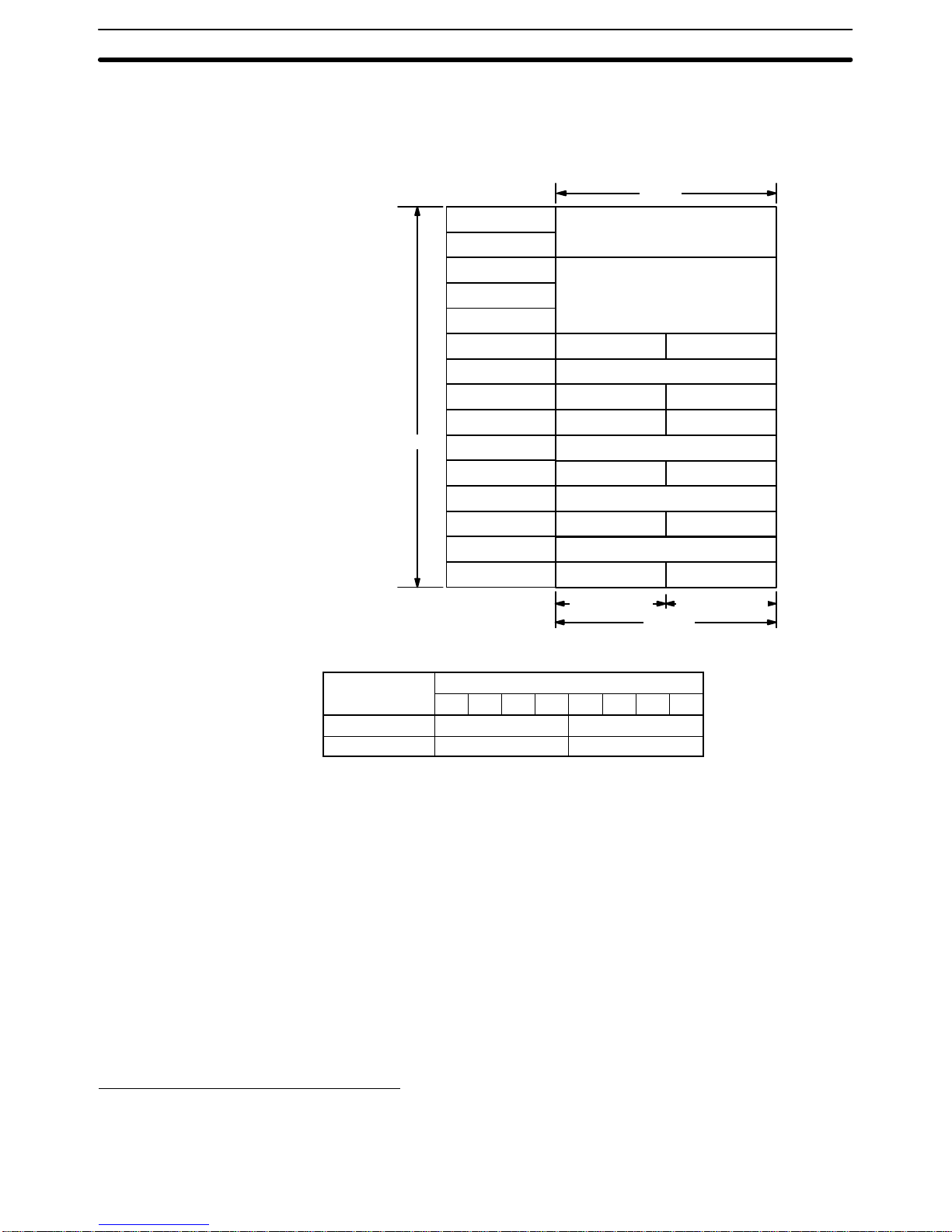
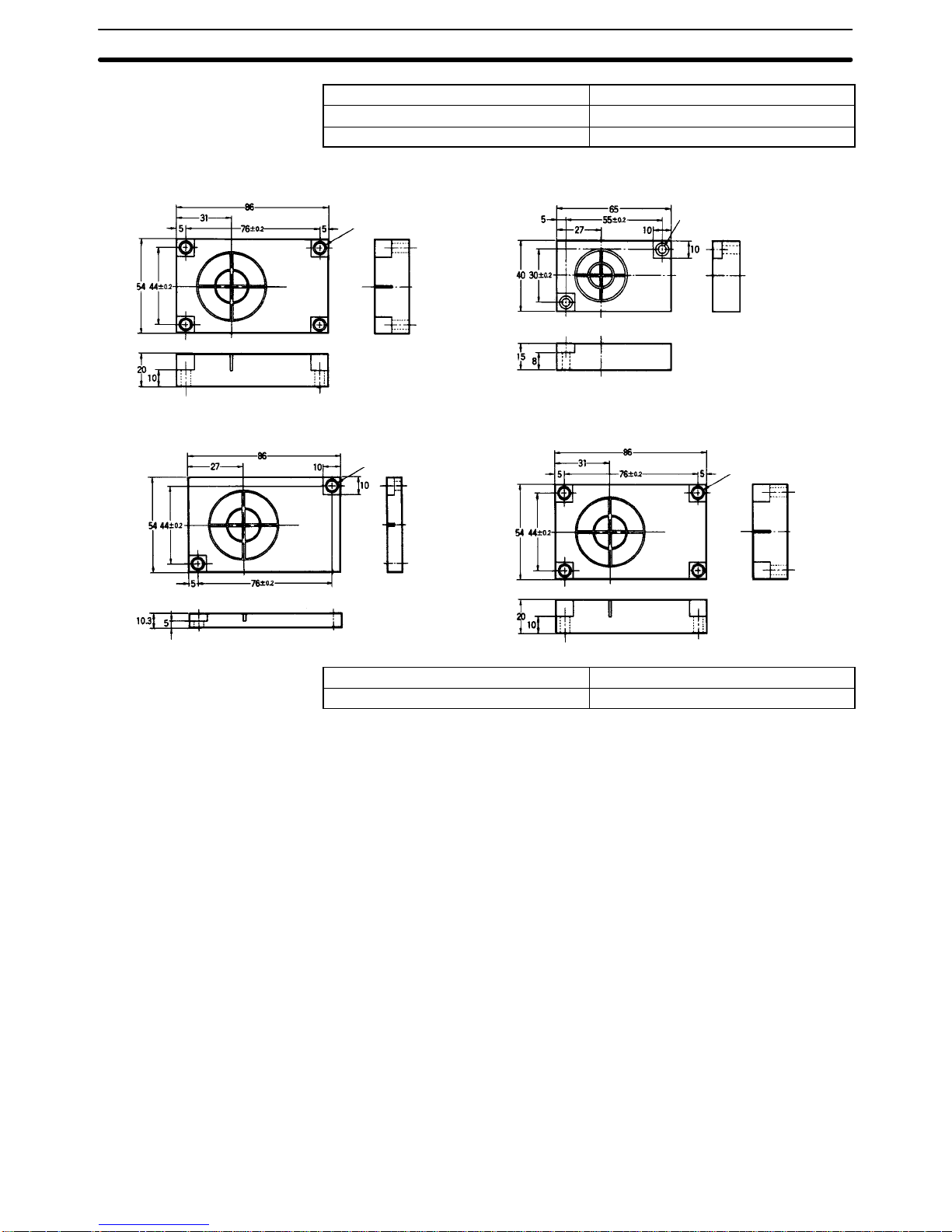
V600-DjKR01
V600-D8KR11
V600-DjKR02
V600-D8KR12
Mounting holes
(four, 4.5 dia.)
Mounting holes
(two, 4.5 dia.)
V600-DjKR03
V600-D8KR13
V600-DjKR04
Mounting holes
(two, 4.5 dia.)
Mounting holes
(four, 4.5 dia.)
Case material ABS resin
Fill resin Epoxy resin
Page 49

49
Appendix C
Other Series
In England, R/W Heads and Data Carriers with a transmission frequency of 470 kHz must be used.
Model: V600-H06-T (R/W Head)
V600-D2KR01-T (Data Carrier)
Except for the transmission frequency, the specifications of the above 470-kHz models are exactly the same as
those of the V600-H06 and V600-D2KR01. For details, refer to Appendix B Discontinued Models and Replace-
ments.
Page 50

51
Revision History
A manual revision code appears as a suffix to the catalog number on the front cover of the manual.
Cat. No. Z127-E1-1
Revision code
The following table outlines the changes made to the manual during each revision. Page numbers refer to the
previous version.
Revision code Date Revised content
1 August 1998 Original production
Page 51

Mouser Electronics
Authorized Distributor
Click to View Pricing, Inventory, Delivery & Lifecycle Information:
Omron:
V600-H12 10M
 Loading...