

Page 1
General Precauti ons
General Precautions
Observe th e following Precautions when using the SYSDRIVE Inv erters and peripheral devices.
This manual may include illustrations of the product with protecti ve covers removed in order to
describe the components of the product in detail. Make sure that these protective covers are on the
product before use.
Consult your OMRON representative when using the pro du ct af ter a long period of storage.
Definition of Precautionary Information
DANGER
WARNING
Caution
Indicates an imminently hazardous situation which, if not avoided, will result in death or
serious injury.
Indicates a potentially hazardous situation which, if not avoided, could result in death or
serious injury.
Indicates a potentially hazardous situation which, if not avoided, may result in minor or
moderate injury, or property damage.
WARNING
WARNING
WARNING
Do not touch the inside of the Inverter. Doing so may result in electric shock or
injury.
Wiring or inspection must be performed only after turning OFF the power supply, confirming that the CHARGE indicator (or status indicator) is OFF and
after waiting for the time specified on the front cover. Not doing so may result
in electrical shock.
Do not damage, pull on, apply stress to, place heavy objects on or pinch the
cables. Doing so may result in electrical shock.
WARNING
WARNING
Caution
Do not touch the rotating parts of the motor under operation. Doing so may
result in injury.
Do not modify the product. Doing so may result in injury or damage to the
product.
Do not store, install or operate the product in the following places. Doing so
may result in electrical shock, fire or damage to the product.
Locations subject to direct sunlight.
•
Locations subject to temperatures or humidity outside the range
•
specified in the specifications.
Locations subject to condensation as the result of severe changes in
•
temperature.
Locations subject to corrosive or flammable gasses.
•
Locations very close to combustable materials.
•
Locations subject to dust (especially iron dust) or salts.
•
Locations subject to exposure to water, oil or chemicals.
•
Locations subject to shock or vibrations.
•
i
Page 2

Caution
Do not touch the Inverters cooling fins, regenerative resistor or the motor
while the power is being supplied or soon after the power is turned OFF. Doing
so may result in a skinburn due to the hot surface.
Caution
Caution
Do not conduct a dielectric stregth test on any part of the Inverter. Doing so
may result in damage to the product or malfunction.
Take appropriate and sufficient countermeasures when installing systems in
the following locations. Not doing so may result in equipment damage.
•
Locations subject to static electricity or other forms of noise.
•
Locations subject to strong electromagnetic fields and magnetic
fields.
•
Locations subject to possible exposure to radio activity.
•
Locations close to power supplies.
ii
Page 3
Transportation Precautions
Transportation Precautions
Caution
Caution
Caution
Do not hold by front cover or panel. Instead hold by the cooling fins (heat
sink) while transporting the product. Doing so may result in injury.
Do not pull on the cables. Doing so may result in damge to the product or malfunction.
Use the eyebolts only for transport of the Inverter. Using them to transport the
Inverter and attached equipment may result in injury or malfunction.
Installation Precautions
Provide an appropriate stopping device on the machine side to secure safety. (
WARNING
WARNING
Caution
A holding brake is not a stopping device for securing safety) Not doing so may
result in injury.
Provide an external emergency stopping device that allows an instantaneous
stop of operation and power interruption. Not doing so may result in injury.
Be sure to install the product in the correct direction and provide specified
clearances between the Inverter and control panel or with other devices to
allow for proper cooling. Not doing so may result in fire or malfunction.
Caution
Caution
Do not allow foreign objects to enter inside the product. Doing so may result in
fire and malfunction.
Do not apply any strong imact. Doing so may result in damage to the product
or malfunction.
Wiring Precautions
WARNING
WARNING
WARNING
Required
Wiring must be performed only after turning OFF the power supply. Not
doing so may result in electrical shock.
Wirin g must be pe rform ed by auth orized pe rsonne l. Not do ing so may re sult in
electrical shock.
Be sur to confirm operation only after wiring the emergency stop circuit. Not
doing so may result in injury.
Always connect the ground terminals to a ground of 100 Ohm or less for 200V AC class or 10 Ohm or less for the 400-V class. Not connecting to a proper
ground may result in electrical shock or fire.
iii
Page 4
Caution
Caution
Install external circuit breakers and take other safety measures against shortcircuiting in external wiring. Not doing so may result in fire.
Confirm that the rated input voltage of the Inverter is the same as the AC
power supply voltage. An incorrect power supply may result in fire, injury or
malfunction.
Caution
Caution
Caution
Caution
Caution
Connect the Braking Resistor or Braking Resistor Unit as specified in th e manual. Not doing so may result in fire.
Be sure to wire correctly and securely. Not doing so may result in injury or
damage to the product .
Be sure to firmly tighten the screws on the terminal block. Not doing so may
result in fire, injury or damage to the product.
Do not conne c t a n A C pow e r s our c e to the U,V,W output. Doi n g so may result
in damage to the product or malfunction.
Do not connect a load to the machine during auto-tuning. Not doing so may
result in equipment damage.
iv
Page 5
Operation and Adjustment Precautions
Operation and Adjustment Precautions
Turn ON the input power supply only after mounting the front cover, terminal
WARNING
WARNING
covers, bottom cover, Operator and optional items. Not doing so may result in
electrical shock.
Do not remove the front cover, terminal covers, bottom cover, Operator or
optional items while the power is being supplied. Doing so may result in electrical shock or damage to the product
WARNING
WARNING
WARNING
WARNING
WARNING
WARNING
Caution
Caution
Do not operate the Operator or switches with wet hands. Doing so may result
in electrical shock.
Do not touch the Inverter terminals while the power is being supplied. Doing
so may result in electrical shock.
Do not come close to the machine when using the error retry function because
the machine may abrupt ly star t when stopped by an al arm. Doin g so m ay result
in injury.
Do not come close to the machine immediately after resetting momentary
power interruption to avoid an unexpected restart (if operation is set to be continued in the processing selection function after momentary power is reset).
Doing so may result in injury.
Provide a separate em ergency stop switc h b eca u se the ST O P K ey on t h e Ope r ator is valid only when function settings are performed. Not doing so may
result in injury.
Be sure to confirm that the RUN signal is turned OFF before tuning ON the
power supply, resetting the alarm or switching the LOCAL/REMOTE selector.
Doing so while the RUN signal is turned ON my result in injury.
Be sure to confirm permissible ranges of motors and machines before operation because the Inverter speed can be easily changed from low to high. Not
doing so may result in damage to the product.
Provide a separate holding brake when neccessary. Not doing so may result in
injury.
Caution
Caution
Do not perform a signal check during operation. Doing so may result in injury
or damage to the product.
Do not carelessly change settings. Doing so may result in injury or damage to
the product.
v
Page 6
Maintenance and Inspection Precautions
WARNING
WARNING
WARNING
Prohibited
Caution
Caution
Do not touch the Inverter terminals while the power is being supplied. Doing
so may result in electrical shock.
Maintenance or inspection must be performed only after turning OFF the
power supply, confirming that the CHARGE indicator (or status indicator) is
OFF and after waiting for the time specified on the front cover. Not doing so
may result in electrical shock.
Maintenance, inspection or parts replacement must be performed by authorized personnel. Not doing so may result in electrical shock or injury.
Do not attempt to disassemble or repair the product. Doing so may result in
electrical shock or injury.
Carefully handle the Inverter because it uses semiconductor elements. Careless
handling may result in malfunction.
Do not exchange, wiring, the Operator, optional cover, disconnect connectors
or replace fans while power is being supplied. Doing so may result in injury,
damage to the product or malfunction.
vi
Page 7
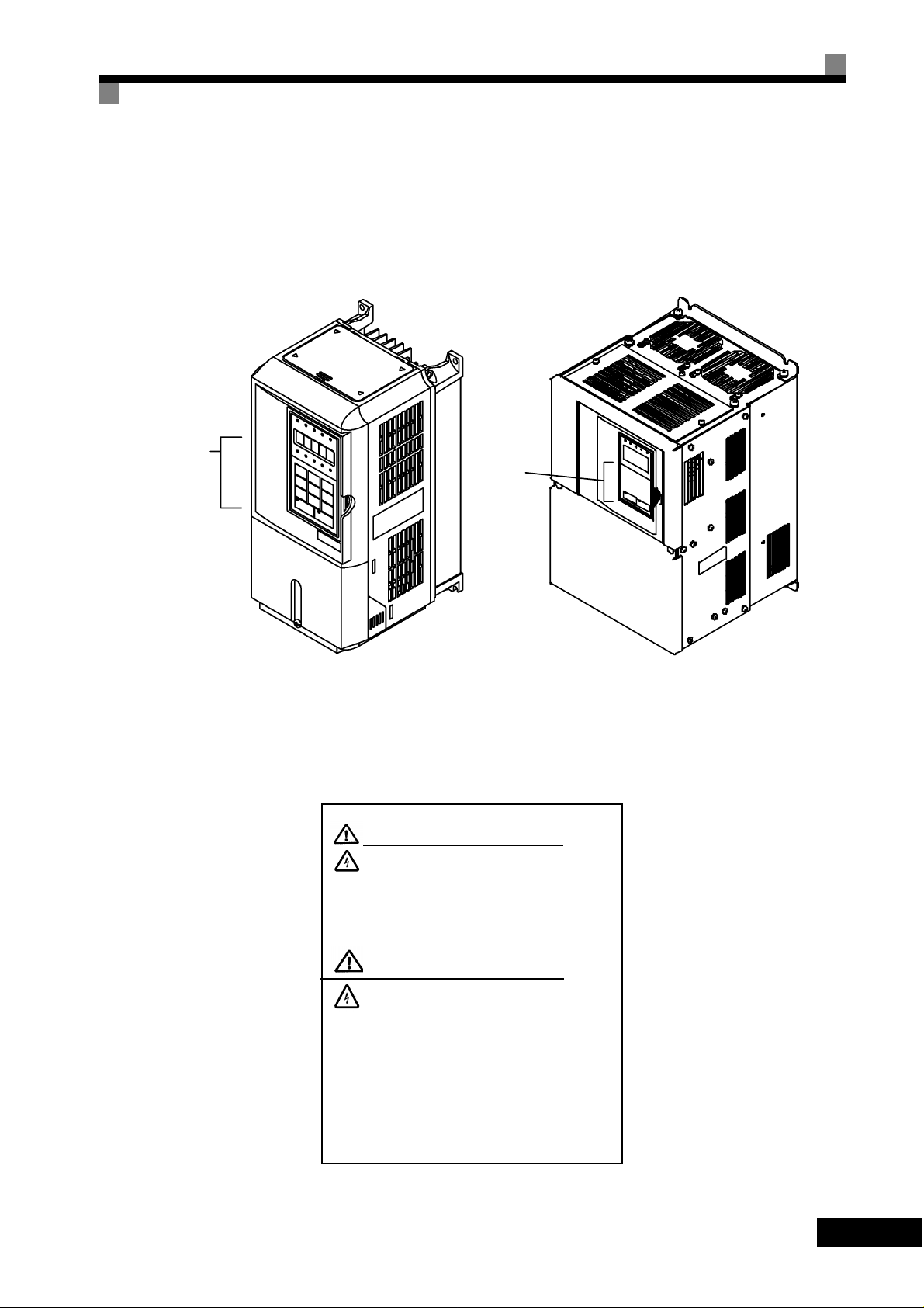
Warning Information and Position
Warning Information and Position
There is warning information on the Inverter in the positon shown in the following illustration.
Aways read the warnings.
Warning
information
position
Warning
information
position
Illustration shows the 3G3PV-A2004-E
Warning information
Illustration shows the 3G3PV-B2220-E
WARNING
Risk of electric shock.
• Read manual before installing.
• Wait 5 minutes for capacitor discharge
after disconnecting powe r supply.
AVERTISSEMENT
Risque de décharge électrique.
• Lire le manual avant l’installation.
• Attendre 5 minutes aprés la coupure de
l’allmentation. Pour permettre la décharge
des condensateurs.
vii
Page 8

Registered Trademarks
The following registered trademarks are used in this manual.
DeviceNet is a registered trademark o f the ODVA (Open DeviceNet Vendors Association,
•
Inc.).
MODBUS is a trademark of the AEG Schneider Automation, Inc.
•
viii
Page 9

Contents
1 Handling Inverters......................... ............................ ............. 1-1
SYSDRIVE PV Introduction..........................................................................1-2
SYSDRIVE PV Applications ...........................................................................................1-2
SYSDRIVE PV Models...................................................................................................1-2
Confirmations upon Delivery ........................................................................1-4
Checks............................................................................................................................1-4
Nameplate Information............................. .... ............................ ..... ........................... ..... .1-4
Component Names.........................................................................................................1-6
Exterior and Mounting Dimensions...............................................................1-8
Open Chassis Inverters (IP00)................................... ............................ .... ....................1-8
Enclosed Wall-mounted Inverters (NEMA 1)..................................................................1-8
Checking and Controlling the Installation Site............................................1-10
Installation Site.............................................................................................................1-10
Controlling the Ambient Temperature...........................................................................1-10
Protecting the Inverter from Foreign Matter..................................................................1-10
Installation Orientation and Space..............................................................1-11
Inverter Installation Orientation and Space...................................................................1-11
Removing and Attaching the Terminal Cover .............................................1-12
Removing the Terminal Cover ......................................................................................1-12
Attaching the Terminal Cover........................................................................................1-12
Removing/Attaching the Digital Operator and Front Cover........................1-13
Inverters of 18.5 kW or Less.........................................................................................1-13
Inverters of 22 kW or More...........................................................................................1-16
2 Wiring....................................................................................... 2-1
Wiring ...........................................................................................................2-2
Connections to Peripheral Devices ..............................................................2-3
Connection Diagrams...................................................................................2-4
Circuit descriptions.........................................................................................................2-5
Terminal Block Configuration........................................................................2-6
Wiring Main Circuit T erminals.......................................................................2-7
Applicable Wire Sizes and Closed-loop Connectors......................................................2-7
Main Circuit Terminal functions ....................................................................................2-12
Main Circuit configurations ...........................................................................................2-13
Standard Connection Diagrams....................................................................................2-14
Wiring the Main Circuits................................................................................................2-15
ix
Page 10

Wiring Control Circuit Terminals.................................................................2-22
Wire Sizes ....................................... ..... .... ............................ .... ..... ............................ ..2-22
Control Circuit Terminal Functions...............................................................................2-24
Control Circuit Terminal Connections...........................................................................2-27
Control Circuit Wiring Precautions ...............................................................................2-28
Wiring Check..............................................................................................2-29
Checks .........................................................................................................................2-29
Installing and Wiring Option Cards.............................................................2-30
Option Card Models and Specifications.......................................................................2-30
Installation....................................................................................................................2-30
3 Digital Operator and Modes....................................................3-1
Digital Operator............................................................................................3-2
Digital Operator Keys.....................................................................................................3-3
Modes ..........................................................................................................3-5
Inverter Modes .......................................... ..... ........................... ..... ..... ...........................3-5
Switching Modes............................................................................................................3-6
Drive Mode.....................................................................................................................3-7
Quick Programming Mode..............................................................................................3-8
Advanced Programming Mode.......................................................................................3-9
Verify Mode.................................................................................................................. 3-11
Autotuning Mode......................... ..... ..... ........................... ..... ........................... ..... .......3-12
4 Trial Operation.........................................................................4-1
Cautions and Warnings................................................................................4-2
Trial Operation Flowchart.............................................................................4-3
Trial Operation Procedures ..........................................................................4-4
Application Confirmation................................................................................................4-4
Setting the Power Supply Voltage Jumper (400-V Class Inverters of 75 kW or Higher) 4-4
Power ON.......................................................................................................................4-4
Checking the Display Status ..........................................................................................4-5
Basic Settings.................................................................................................................4-6
Selecting the V/f pattern.................................................................................................4-7
Application Settings......................................................................................................4-10
No-load Operation..................................... ............................ .... ............................ ..... ..4-10
Loaded Operation......................................................................................................... 4-11
Adjustment Suggestions ............................................................................4-13
5 Parameters...............................................................................5-1
Parameter Descriptions................................................................................5-2
Description of Parameter Tables ....................................................................................5-2
Digital Operator Display Functions and Levels ............................................5-3
x
Page 11

Parameters Settable in Quick Programming Mode........................................................5-4
Parameter Tables .........................................................................................5-7
A: Setup Settings............................................................................................................5-7
Application Parameters: b........... ..... .... ............................ .... ............................ ..... .... ......5-8
Tuning Parameters: C...................................................................................................5-13
Reference Parameters: d..............................................................................................5-16
Motor Constant Parameters: E.....................................................................................5-18
Option Parameters: F...................................................................................................5-19
Terminal Function Parameters: H.................................................................................5-20
Protection Function Parameters: L...............................................................................5-26
N: Special Adjustments.................................................................................................5-32
Digital Operator Parameters: o.....................................................................................5-33
T: Motor Autotuning......................................................................................................5-36
U: Monitor Parameters.................................................................................................. 5-37
Factory Settings that Change with the Inverter Capacity (o2-04).................................5-44
6 Parameter Settings by Function............................................ 6-1
Application and Overload Selections............................................................6-2
Select the Overload to Suit the Application....................................................................6-2
Frequency Reference...................................................................................6-4
Selecting the Frequency Reference Source...................................................................6-4
Using Multi-Step Speed Operation......................................................... .... ....................6-6
Run Command .............................................................................................6-8
Selecting the Run Command Source ............................................................................. 6 -8
Stopping Methods..... ................................. ..... ...... ................................ ......6-10
Selecting the Stopping Method when a Stop command is Input..................................6-10
Using the DC Injection Brake........................................................................................6-13
Using Highslip Braking........... ..... ............................ .... ............................ .... ..................6-14
Using an Emergency Stop............................................................................................6-16
Acceleration and Deceleration Characteristics...........................................6-17
Setting Acceleration and Deceleration Times...............................................................6-17
Preventing the Motor from Stalling During Acceleration
(Stall Prevention During Acceleration Function)...........................................................6-19
Preventing Overvoltage During Decelera tion
(Stall Prevention During Deceleration Function)...........................................................6-21
Adjusting Frequency References ...............................................................6-22
Adjusting Analog Frequen cy Refer en ces........................ .... ..... ............................ ........6-22
Operation Avoiding Resonance (Jump Frequency Function).......................................6-24
Speed Limit (Frequency Reference Limit Function)...................................6-26
Limiting Maximum Output Frequency...........................................................................6-26
Limiting Minimum Frequency........................................................................................6-26
Improved Operating Efficiency ...................................................................6-27
Field-weakening option........................ ............................ .... ............................ ..... ........6-28
Hunting-prevention Function.........................................................................................6-29
xi
Page 12

Machine Protection ....................................................................................6-30
Preventing Motor Stalling During Operation.................................................................6-30
Detecting Motor Torque................................................................................................6-30
Motor Overload Protection ...........................................................................................6-33
Motor Overheating Protectio n Using PT C Therm is tor Input s.......................................6-35
Continuing Operation .................................................................................6-37
Restarting Automatically After Power Is Restored .................... ..... ............................ ..6-37
Speed Search...............................................................................................................6-38
Continuing Operation at Con sta nt Sp ee d When Fre qu en cy Reference Is Lost...........6-43
Restarting Operation After Transient Fault (Auto Restart Function) ............................6-43
Inverter Protection......................................................................................6-45
Reducing Inverter Overheating Pre-Alarm Warning Levels .........................................6-45
Input Terminal Functions............................................................................6-46
Temporarily Switching Operation between Digital Operator
and Control Circuit Terminals.......................................................................................6-46
Blocking Inverter Outputs (Baseblock Commands)......................................................6-46
Hold Analog Frequency Using User-set Timing...........................................................6-47
Switching Operations between a Communications Option Card
and Control Circuit Terminals.......................................................................................6-48
Jog Frequency Operation wit hout Forward and Reverse Commands
(FJOG/RJOG) ..............................................................................................................6-48
Stopping the Inverter by Notifying Programming Device Errors to the Inverter
(External Error Function)..............................................................................................6-49
Monitor Parameters....................................................................................6-50
Using the Analog Monitor Parameters .........................................................................6-50
Individual Functions ...................................................................................6-52
Using PI Control...........................................................................................................6-65
Energy-saving..............................................................................................................6-72
Setting Motor Constant Parameters.............................................................................6-73
Setting the V/f Pattern..................................................................................................6-74
Digital Operator Functions .........................................................................6-80
Setting Digital Operator Functions ...............................................................................6-80
Copying Parameters.....................................................................................................6-82
Prohibiting Writing Parameters from the Digital Operator............................................6-86
Setting a Password ......................................................................................................6-86
7 Troubleshooting......................................................................7-1
Protective and Diagnostic Functions............................................................7-2
Fault Detection........................ .... ..... ............................ .... ............................ .... ..... .........7-2
Alarm Detection..............................................................................................................7-7
Operation Errors.............................................................................................................7-9
Errors During Autotuning.............................................................................................7-10
Errors when Using the Digital Operator Copy Function ...............................................7-11
xii
Troubleshooting..........................................................................................7-12
Page 13

If Parameters Cannot Be Set........................................................................................7-12
If the Motor Does Not Operate......................................................................................7-13
If the Direction of the Motor Rotation is Reversed........................................................7-14
If the Motor Does Not Put Out Torque or If Acceleration Is Slow..................................7-15
If the Motor Operates Higher Than the Reference .......................................................7-15
If Motor Deceleration Is Slow........................................................................................7-15
If the Motor Overheats..................................................................................................7-16
If peripheral devices are influenced by starting the Inverter......................................... 7-16
If the Ground Fault Interrupter Operates When the Inverter Is Run.............................7-17
If There Is Mechanical Oscillation.................................................................................7-17
If the Motor Rotates Even When Inverter Output Is Stopped.......................................7-17
If 0 V Is Detected When the Fan Is Started, or the Fan Stalls......................................7-18
If Output Frequency Does Not Rise to Frequency Reference......................................7-18
8 Maintenance and Inspection.................................................. 8-1
Maintenance and Inspection.........................................................................8-2
Daily Inspection..............................................................................................................8-2
Periodic Inspection................................... .... ..... ............................ .... ............................ .8-2
Periodic Maintenance of Parts........................................................................................8-3
Cooling Fan Replacement Outline..................................................................................8-4
Removing and Mounting the Control Circuit Terminal Card...........................................8-6
9 Specifications ......................................................................... 9-1
Standard Inverter Specifications...................................................................9-2
Specifications by Model............................ ........................... ..... ............................ .... ..... .9-2
Common Specifications..................................................................................................9-5
Specifications of Options and Peripheral Devices........................................9-6
Options and Peripheral Devices...................................................................9-7
Special Mounted Options................................................................................................9-9
Separately Installed Options.........................................................................................9-10
10 Inverter application Precautionspendix ............................. 10-1
Selection.......................................................................................................................10-2
Installation.....................................................................................................................10-3
Settings.........................................................................................................................10-3
Handling........................................................................................................................10-4
Motor Application Precautions......................................................... ..... ......10-5
Using the Inverter for an Existing Standard Motor........................................................10-5
Using the Inverter for Special Motors...........................................................................10-6
Power Transmission Mechanism (Speed Reducers, Belts, and Chains)......................10-6
Wiring Examples.........................................................................................10-7
Using a Braking Resistor Unit.......................................................................................10-7
Using a Braking Unit and Braking Resistor Unit...........................................................10-7
Using a Braking Unit and Three Braking Resistor Units in Parallel..............................10-9
xiii
Page 14

Using an Analog Operator..........................................................................................10-10
Parameters............................................................................................... 10-11
Revision History ................. ................................. ...... ..... ..........................10-14
xiv
Page 15

1
Chapter 1
Handling Inverters
This chapter describes the checks required upon receiving or installing an Inverter.
SYSDRIVE PV Introduction..................................................1-2
Confirmations upon Delivery.................................................1-4
Exterior and Mounting Dimensions.......................................1-8
Checking and Controlling the Instal lat io n Site....................1-11
Installation Orientation and Space.......................................1-12
Removing and Attaching the Terminal Cover......................1-13
Removing/Attaching the Digital Oper ator
and Front Cover....................................................................1-14
Page 16
SYSDRIVE PV Introduction
SYSDRIVE PV Applications
The SYSDRIVE PV is ideal for the following applications.
•
Fan, blower and pump applications
Settings must be adjusted to the application for optimum operation. Refer to Chapter 4 Trial Operation.
SYSDRIVE PV Models
The SYSDRIVE PV Series of Inverters inclu des two kinds of Inverters in two voltage classes: 200 V and
400 V. Maximum motor capacities vary from 0.4 to 160 kW.
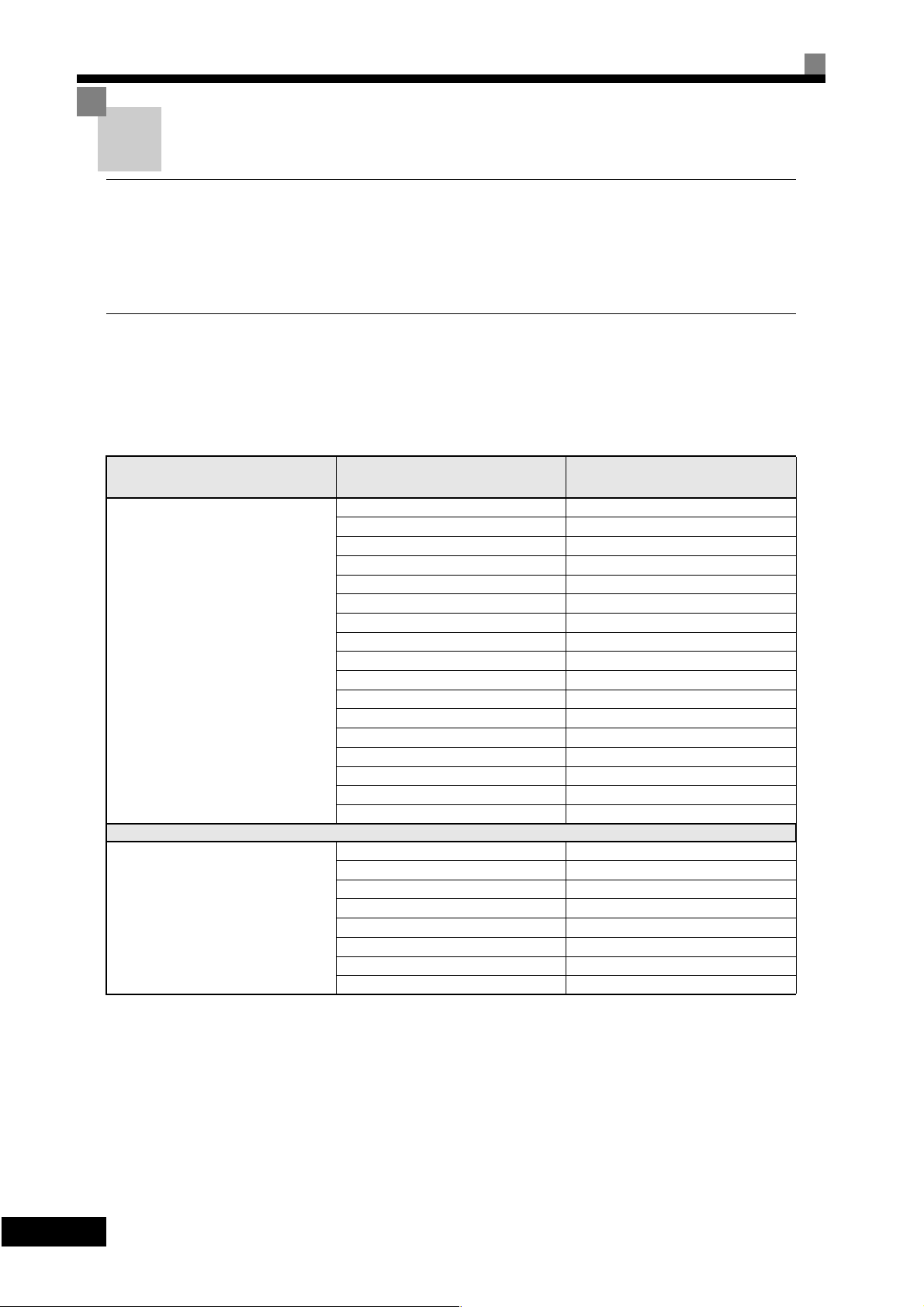
Table 1.1 SYSDRIVE PV Models
Protective Structure Maximum Motor Capa city Basic Model Number
NEMA 1 type
IP20
(200 V class)
Open Chassis type
IP00
(200 V class)
0.4
0.75
1.5
2.2
3.7
5.5
7.5
11
15
18.5
22
30
37
45
55
75
90
22
30
37
45
55
75
90
110
kW
kW
kW
kW
kW
kW
kW
kW
kW
kW
kW
kW
kW
kW
kW
kW
kW
kW
kW
kW
kW
kW
kW
kW
kW
3G3PV-A2004-E
3G3PV-A2007-E
3G3PV-A2015-E
3G3PV-A2022-E
3G3PV-A2037-E
3G3PV-A2055-E
3G3PV-A2075-E
3G3PV-A2110-E
3G3PV-A2150-E
3G3PV-A2185-E
3G3PV-A2220-E
3G3PV-A2300-E
3G3PV-A2370-E
3G3PV-A2450-E
3G3PV-A2550-E
3G3PV-A2750-E
3G3PV-A2900-E
3G3PV-B2220-E
3G3PV-B2300-E
3G3PV-B2370-E
3G3PV-B2450-E
3G3PV-B2550-E
3G3PV-B2750-E
3G3PV-B2900-E
3G3PV-B211K-E
1
-2
Page 17

SYSDRIVE PV Introduction
Protective Structure Maximum Mo to r Capacity Basic Model Number
0.4 kW 3G3PV-A4004-E
0.75 kW 3G3PV-A4007-E
1.5 kW 3G3PV-A4015-E
2.2 kW 3G3PV-A4022-E
3.7 kW 3G3PV-A4037-E
4.0 kW 3G3PV-A4040-E
5.5 kW 3G3PV-A4055-E
7.5 kW 3G3PV-A4075-E
NEMA 1 type
IP20
400 V class
11 kW 3G3PV-A4110-E
15 kW 3G3PV-A4150-E
18.5 kW 3G3PV-A4185-E
22 kW 3G3PV-A4220-E
30 kW 3G3PV-A4300-E
37 kW 3G3PV-A4370-E
45 kW 3G3PV-A4450-E
55 kW 3G3PV-A4550-E
75 kW 3G3PV-A4750-E
90 kW 3G3PV-A4900-E
110 kW 3G3PV-A411K-E
132 kW 3G3PV-A413K-E
160 kW 3G3PV-A416K-E
Open Chassis type
IP00
(400 V class)
22 kW 3G3PV-B4220-E
30 kW 3G3PV-B4300-E
37 kW 3G3PV-B4370-E
45 kW 3G3PV-B4450-E
55 kW 3G3PV-B4550-E
75 kW 3G3PV-B4750-E
90 kW 3G3PV-B4900-E
110 kW 3G3PV-B411K-E
132 kW 3G3PV-B413K-E
160 kW 3G3PV-B416K-E
1
-
3
Page 18
Confirmations upon Delivery
Checks
Check the following items as soon as the Inverter is delivered.
Table 1.2 Checks
Item Method
Has the correct model of Inverter been
delivered?
Is the Inverter damaged in any way?
Are any screws or other compone nts
loose?
If you find any irregularities in the above items, contact the agency from which you purchased the In verter or
your OMRON representative immediately.
Nameplate Information
Check the model number on the nameplate on t he side of the I nverter.
Inspect the entire exterior of the Inverter to see if there are any scratches or
other damage resulting from shipping.
Use a screwdriver or other tools to check for tightness.
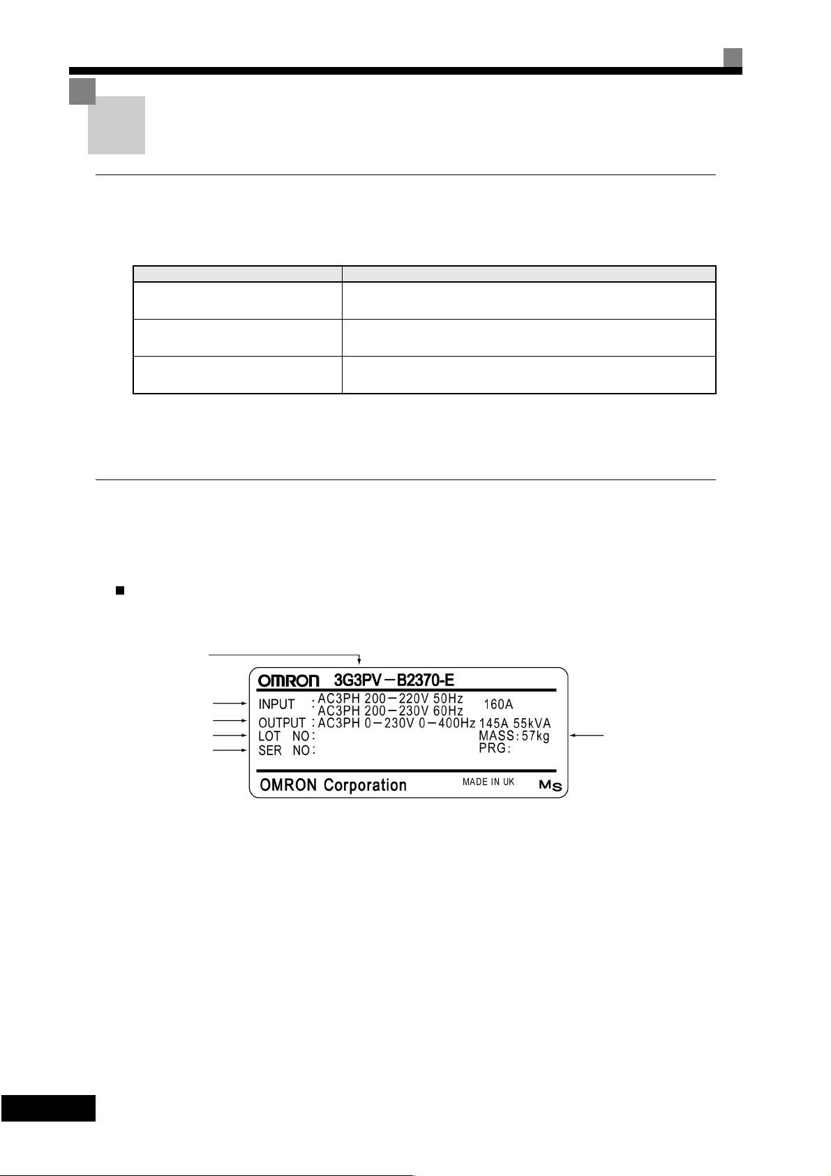
There is a nameplate attached to the side of each Inverter. The nameplate shows the model n umber, specifications, lot number, serial number and other information on the Inverter.
Example Nameplate
The following nameplate is an example for an European Inverter: 3-phase, 200 VAC, 37 kW, IEC IP00
Inverter model
Input specification
Output specification
Lot number
Serial number
Fig 1.1 Namepla te
Mass
1
-4
Page 19
Confirmations upon Delivery
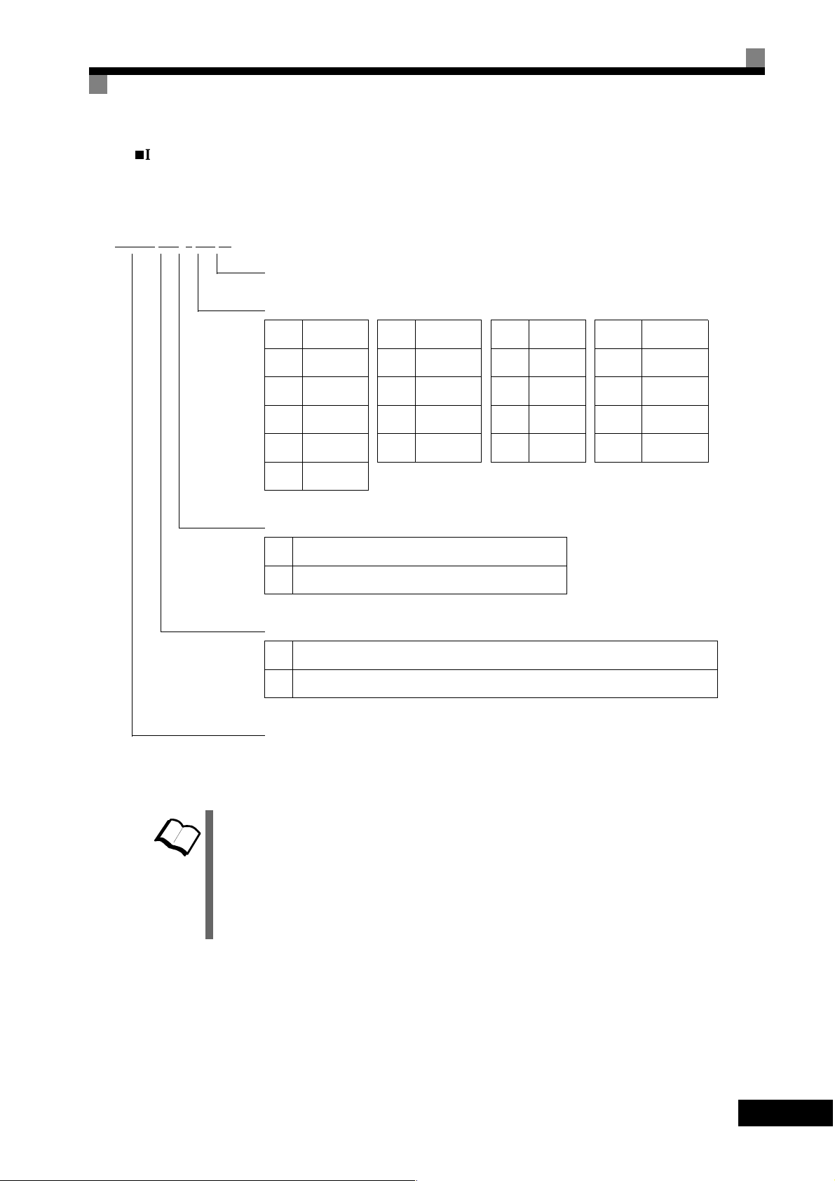
Inverter Model Numbers
The model number of the Inverte r on the nameplate indicates the specification, vo ltage class and maximum
motor capacity of the Inverter in alphanumeric codes.
G3PV -A 2 037 -E
Specifications -E (European Model)
Maximum Applicable Motor Capacity
004 0.4 kW 055 5.5 kW 220 22 kW 750 75 kW
007 0.75 kW 075 7.5 kW 300 30 kW 900 90 kW
015 1.5 kW 110 11 kW 370 37 kW 11K 110 kW
022 2.2 kW 150 15 kW 450 45 kW 13K 130 kW
037 3.7 kW 185 18.5 kW 550 55 kW 16K 160 kW
TERMS
040 4.0 kW
Voltage Class
2 AC-input, 3-phase, 200 V (200-V Class)
4 AC-input, 3-phase, 400 V (400-V Class)
Installation type
A Panel mounting or closed wall-mounting (IEC IP20, NEMA 1)
B Open Chassis (IEC IP00)
Series Name 3G3PV Series
Fig 1.2 Inverter Model Numbers
Open Chassis Type (IEC IP00)
Protected so that parts of the human b ody cannot reach electrically charged pa rts from the front when the
Inverter is mounted in a control panel.
Enclosed Wall-mounted Type (IEC IP20, NEMA Type 1)
The Inverter is structured so that the Inverter is shielded from the exterior and can t hus be mounted to the
interior wall of a standard building (not necessarily enclosed in a control panel). The protective structure conforms to the standards of NEMA 1 in the USA.
Top protective cover (Fig. 1.3) has to be installed to conform with IEC IP20 and NEMA Type 1 requirements.
1
-
5
Page 20
Component Names
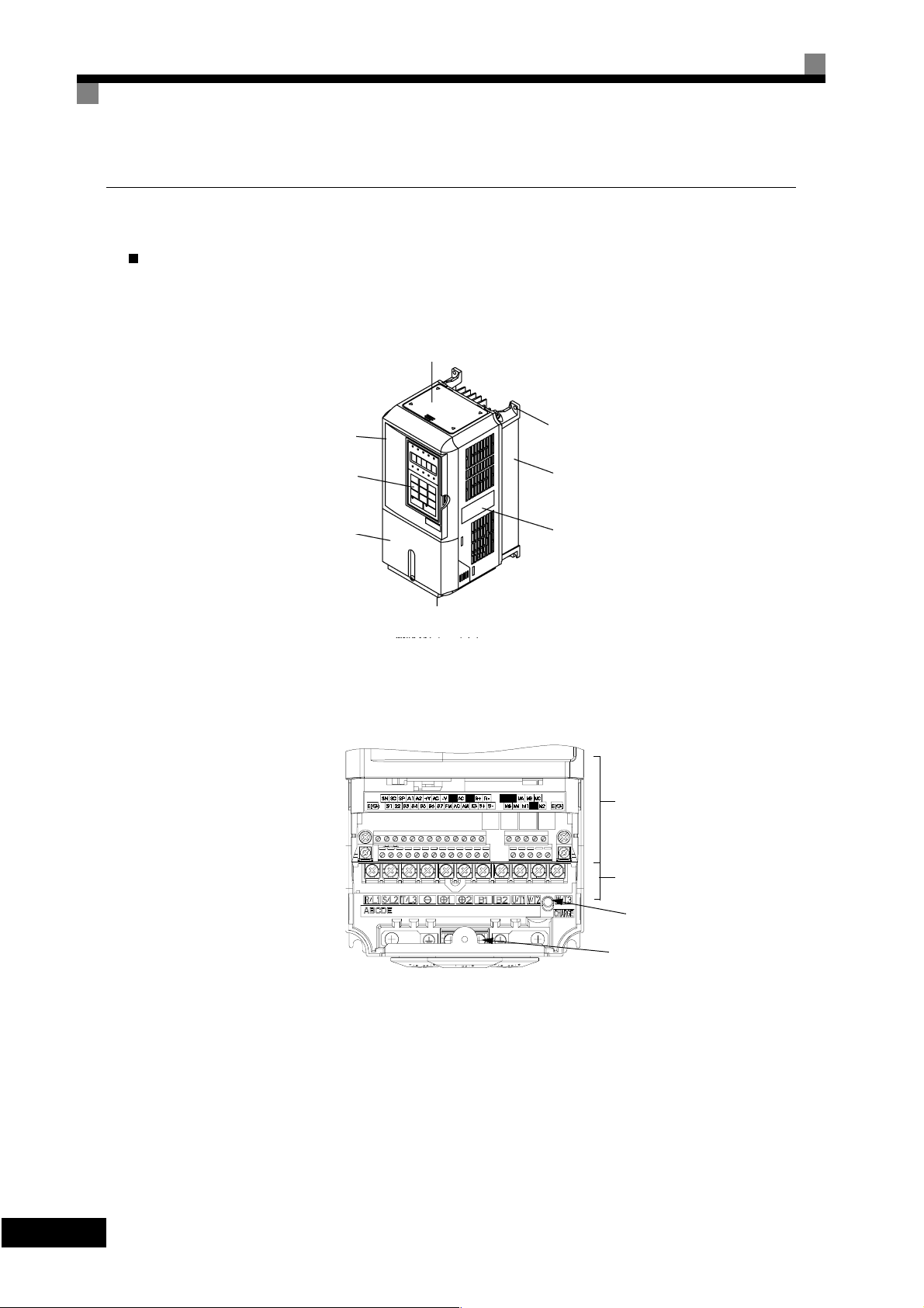
Inverter Appearance
The external appearance and component names of the Inverter are shown in Fig 1.3. The Inverter with the terminal cover removed is shown in Fig 1.4.
Top protective cover (Part of Enclosed Wall-
mounted Type (IEC IP20, NEMA Type 1)
Front cover
Digital Operator
Terminal cover
Mounting hole
Diecast case
Nameplate
Bottom protective cover
Fig 1.3 Inverter Appeara nce (18.5 kW or Less)
Control circuit terminals
Main circuit termina l s
1
Charge indicator
Ground terminal
Fig 1.4 Terminal Arra ngement (18. 5 kW or Less)
-6
Page 21
Confirmations upon Delivery
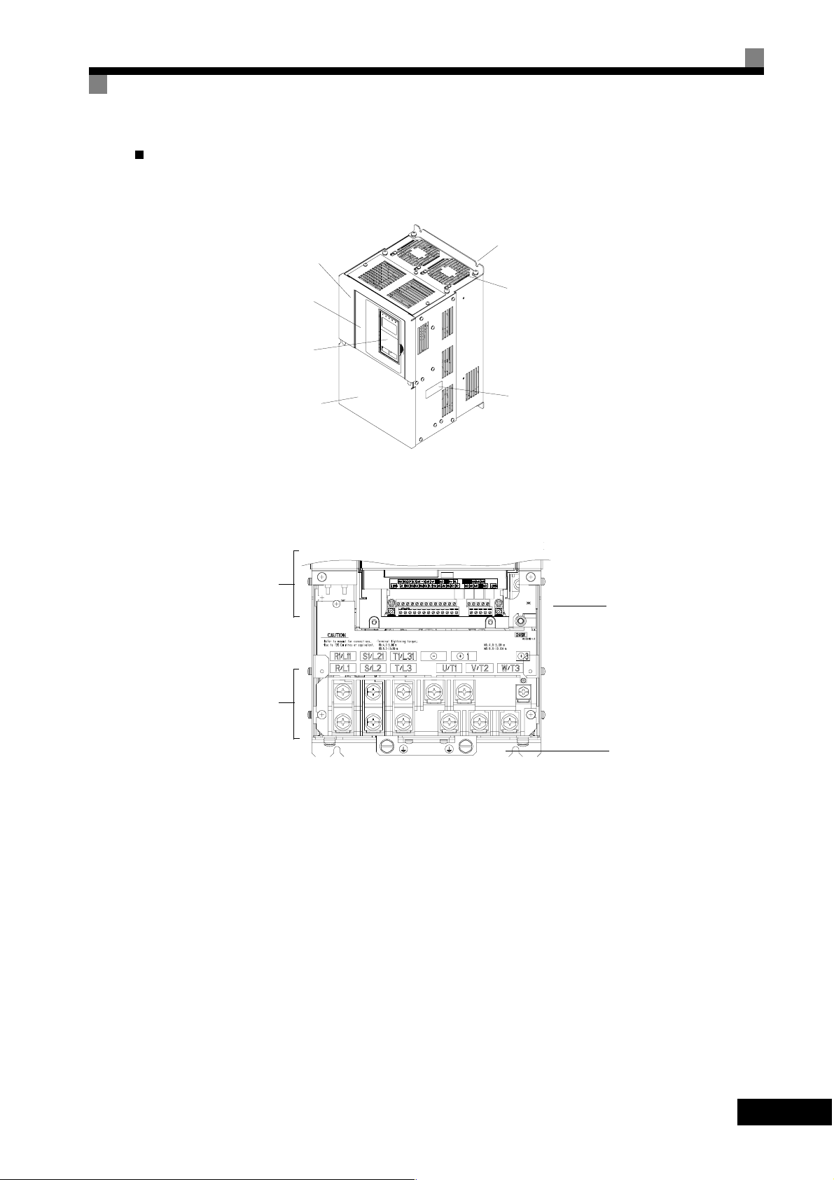
Inverters of 22 kW or More
The external appearance and component names of the Inverter are shown in Fig 1.5. The Inverter with the terminal cover removed is shown in Fig 1.6.
Mounting holes
Inverter cover
Front cover
Digital Operator
Cooling fan
Terminal cover
Control
Control
circuit
circuit
terminals
terminals
Main
circuit
terminals
Nameplate
Fig 1.5 Inverter Appearanc e (22 kW or More)
Charge indicator
Ground terminal
Fig 1.6 Terminal Arrangement (22 kW or More )
1
-
7
Page 22
Exterior and Mounting Dimensions
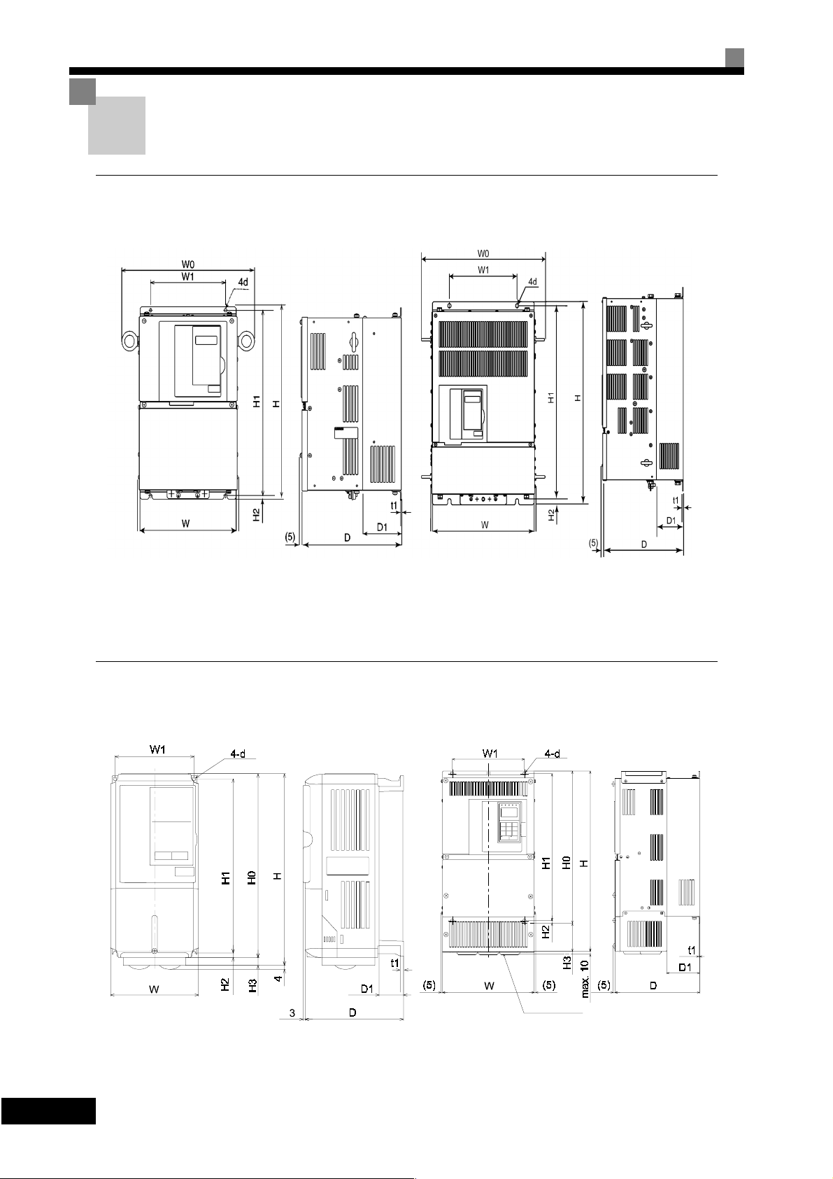
Open Chassis Inverters (IP00)
Exterior diagrams of the Open Chassis Inverters are shown below.
200 V Class Inverters of 22 or 30 kW
400 V Class Inverters of 22 to 55 kW
Fig 1.7 Exterior Diagrams of Open Chassis Inverters
Enclosed Wall-mounted Inverters (NEMA1)
Exterior diagrams of the Enclosed Wall-mounted Inverters (NEMA1) are shown below.
200 V Class Inverters of 37 to 110 kW
400 V Class Inverters of 75 to 160 kW
1
-8
200 V/400 V Class Inverters of 0.4 to 18.5 kW
Fig 1.8 Exterior Diagrams of Enclosed Wall-mounted Inverters
Grommet
200 V Class Inverters of 22 to 90 kW
400 V Class Inverters of 22 to 160 kW
Page 23
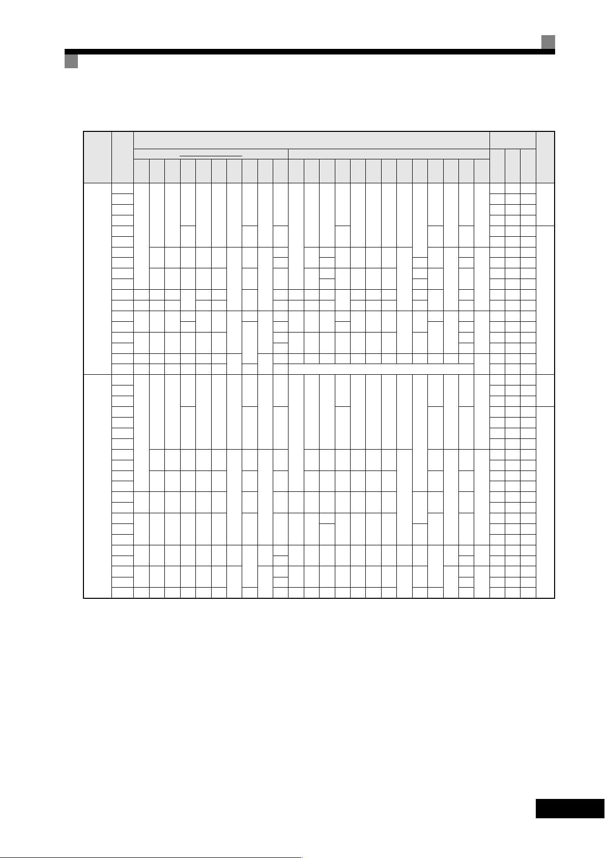
Table 1.3 Inverter Dimensions (mm) and Masses (kg)
Max.
Appli-
Voltage
cable
Class
Motor
Output
W0 W H D W1 H1 H2 D1 t1
[kW]
0.4
0.75 27 42 69
1.5 50 50 100
2.2 70 59 129
3.7
-
5.5 164 84 248
7.5
11 7 310 10 7 374 170 544
(3-phase)
18.5 380 30 501 211 712
15
200 V
22 345 254 400
30 370 279 450 220 435 24 370 280 615 220 450 435 165 27 865 352 1217
37
470 379 600
45 328
55
545 454 725 348 325 700
75 87 95 2019 838 997
90 615 505 850 358 370 820
110 690 579 885 378 445 855 140 150 Not available. Use IP00 type.- 2733 1242 3975
0.4
0.75 17 41 58
1.5 36 48 84
2.2
3.7 80 68 148
-
4.0 70 91 161
5.5 127 82 209
7.5
11 252 158 410
15
400 V
(3-phase)
18.5 426 208 634
22
370 280 450 258 220 435 100 21 370 280 535 258 220 450 435
30 678 317 995
37
420 329 550 283 260 535 105 36 420 329
45
55 1203 495 1698
75
545 454 725 348 325 700 13
90 89 97 1614 671 2285
110
615 505 850 358 370 820
132 120 130 2388 1002 3390
160 689 579 916 378 445 855 140 160 689 579 1325 378 445 916 855 400 140 170 2791 1147 3938
* Same for Open Chassis and Enclosed Wall-mounted Inverters.
Open Chassis (IP00) Enclosed Wall-moun ted (NEMA1, IP20)
140 280
157
126 266 7
39
177 59 4 177 59 4
200 300 197 186 285
240 350 207 216 335 78 11 240
195 385
258
298
250 575
65.5
7.5
100
100
13
130
15 4.5
140 280
157
126 266 7
39
177 59 4 177 59 4
200 300 197 186 285
65.5
240 350 207 216 335 78 10 240 350 207 216 350 335 78 10
7.5
130
15 4.5
Exterior and Mounting Dimensions
Dimensions (mm)
Ap-
prox.
W0 W H D W1 H0 H1 H2 H3 D1 t1
Mass
3
5
140 280
-
6
200
2.3
21 345 255 535
57
470 380 809
63 330
3.2
86
545 455 1027 350 325 725 700 305
108 615 504 1243 360 370 828 820 7.8 408 130 4.5 114
3
5
140 280
-
6 200 300 197 186 300 285
2.3
88
3.2
545 454 1100 348 325 725 700 13 305
102
615 505 1245 358 370 850 820
157
126 280 266 7
300
197 186 300 285
350
207 216 350 335
195 400 385 135
258
300
250 600 575
7.5
13
210
0
65.5
0
100
100
130
157
126 280 266 7
0
65.5
7.5
100 24
85
635
283 260 550 535 105 40
715 165
130
395
15
39
78 11
39
Exter
Mount-
Ap-
ing
Holes
d*
nal
prox.
Mass
20 39 59
3
5
M5
112 74 186
6
219 113 332
2.3
429 183 612
M6
24 586 274 860
62
1015 411 1426
68 1266 505 1771
3.2
M10
94 1588 619 2207
2437 997 3434
M12
14 39 53
3
5
M5
59 56 115
193 114 307
6
326 172 498
2.3
466 259 725
M6
784 360 1144
901 415 1316
96
122
1399 575 1974
M10
2097 853 2950
M12
3.2
4.5
Caloric
Value(W)
Inter-
nal
Tot a l
Heat
Gen-
eration
Cool-
ing
Method
Natu-
ral
Fan
Natu-
ral
Fan
1
-
9
Page 24

Checking and Controlling the Installation Site
Install the Inverter in the installation site described below and maintain optimum conditions.
Installation Site
Install the Inverter under the following conditions in a pollution degree 2 environment.
Table 1.4 Installation Site
Type Ambient Operating Temperature Humidity
Enclosed wall-mounte d -10 to + 40 °C 95% RH or less (no condensation)
Open chassis -10 to + 45 °C 95% RH or less (no condensation)
Protection covers are attached to the top and bo ttom of the Inverter. Be sure to remove the protection covers
before installing a 200 or 400 V Class Inverter with an output of 18.5 kW or less in a panel.
Observe the following precautions when mounting the Inverter.
•
Install the Inverter in a clean location which is free from oil mist and dust. It can be installed in a totally
enclosed panel that is completely shielded from floating dust.
•
When installing or operating the Inverter, always take special care so that metal powder, oil, water or other
foreign matter does not get into the Inverter.
•
Do not install the Inverter on combustible material, such as wood.
•
Install the Inverter in a location free from radioactive materials and combustible materials.
•
Install the Inverter in a location free from harmful gasses and liquids.
•
Install the Inverter in a location without excessive oscillation.
•
Install the Inverter in a location free from chlorides.
•
Install the Inverter in a location not in direct sunlight.
Controlling the Ambient Temperature
To enhance the reliability of operation, the Inverter should be installed in an environment free from extreme
temperature increases. If the Inverter is installed in an enclosed environment, such as a box, use a cooling fan
or air conditioner to maintain the internal air temperature below 45×C.
Protecting the Inverter from Foreign Matte r
Place a cover over the Inverter during installation to shield it from metal power produced by drilling.
Always remove the cover from the Inverter after completing installation. Otherwise, ventilation will be
reduced, causing the Inverter to overheat.
-10
1
Page 25
Installation Orientation and Space
Provide an appropriate stopping device on the machine side to secure safety. (
WARNING
A holding brake is not a stopping device for securing safety) Not doing so may
result in injury.
Installation Orientation and Space
WARNING
Caution
Caution
Caution
Inverter Installation Orientation and Space
Install the Inverter vertically so as not to r educe the cooling effect. When installing the In verter, always
provide the following installation space to allow normal heat dissipation.
50 mm min.
Provide an external emergency stopping device that allows an instantaneous
stop of operation and power interruption. Not doing so may result in injury.
Be sure to install the product in the correct direction and provide specified
clearances between the Inverter and control panel or with other devices to
allow for proper cooling. Not doing so may result in fire or malfunction.
Do not allow foreign objects to enter inside the product. Doing so may result in
fire and malfunction.
Do not apply any strong imact. Doing so may result in damage to the product
or malfunction.
120 mm min.
Air
50 mm min.
IMPORTANT
30 mm min.
1. The same space is required horizontally and v ertically for both Open Chas sis (IP00) and Enclos ed Wall-
2. Always re move the protection covers before installing a 200 or 400 V Class Inverter with an outpu t of
30 mm min.
Fig 1.9 Inverter Installation Orientation and Space
mounted ( I P20, NEMA 1) Invert ers.
18.5 kW or less in a panel.
Always provide enough space for suspension eye bolts and the main circuit lines when installing a 200 or
400 V Class Inverter with an output of 22 kW or more in a panel.
120 mm min.
Vertical SpaceHorizontal Space
Air
1
-
11
Page 26
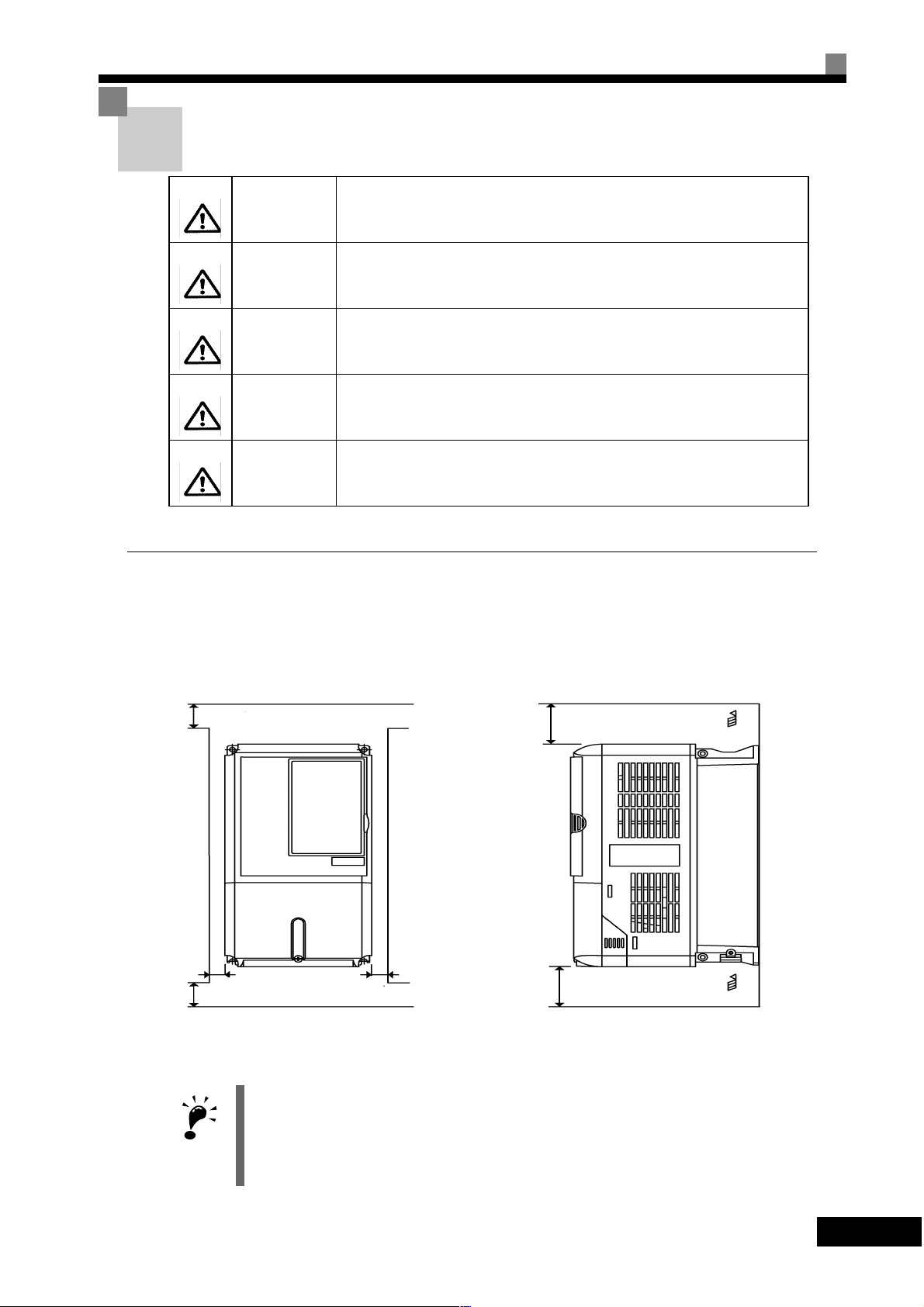
Removing and Attaching the Terminal Cover
Remove the terminal cover to wire cables to the control circuit and main circuit terminals.
Removing the Terminal Cover
Inverters of 18.5 kW or Less
Loosen the screw at the bottom of the terminal cover, press in on the sides of the terminal cover in the direc tions of arrows 1 and then lift up on the terminal in the direction of arrow 2.
1
2
1
Fig 1.10 Removing the Terminal Cover (Model 3G3PV-A2055-E Shown Above)
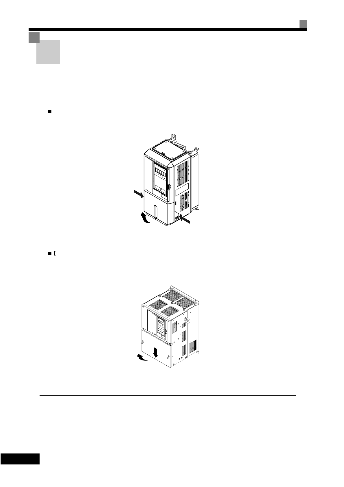
Inverters of 22 kW or More
Loosen the screws on the left and right at the top of the terminal cover, pull out the terminal cover in the direction of arrow 1 and then lift up on the terminal in the direction of arrow 2.
1
2
Fig 1.11 Removing the Terminal Cover (Model 3G3PV-B2220-E Shown Above)
Attaching the Terminal Cover
-12
1
When wiring the terminal block has been completed, attach the terminal cover by reversing the removal procedure.
For Inverters with an output of 18.5 kW or less, insert the tab on the top of the terminal cover into the groove
on the Inverter and press in on the bottom of the terminal cover until it clicks into place.
Page 27
Removing/Attaching the Digital Operator and Front Cover
Removing/Attaching the Digital Operator and Front
Cover
Inverters of 18.5 kW or Less
To attach optional cards or change the terminal card connector, remove the Digital Operator and front cover in
addition to the terminal cover. Always remove the Digital Operator from the front cover before removing the
terminal cover.
The removal and attachment procedures are given below.
Removing the Digit al Operator
Press the lever on the side of the Digital Operator in the direction of arrow 1 to unlock the Digital Operator
and lift the Digital Operator in the direction of arrow 2 to remove the Digital Operator as shown in the following illustration.
2
Fig 1.12 Removing the Digital Operator (Model 3G3PV-A4055-E Shown Above)
1
1
-
13
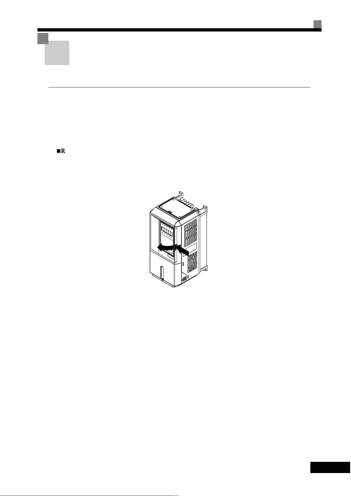
Page 28
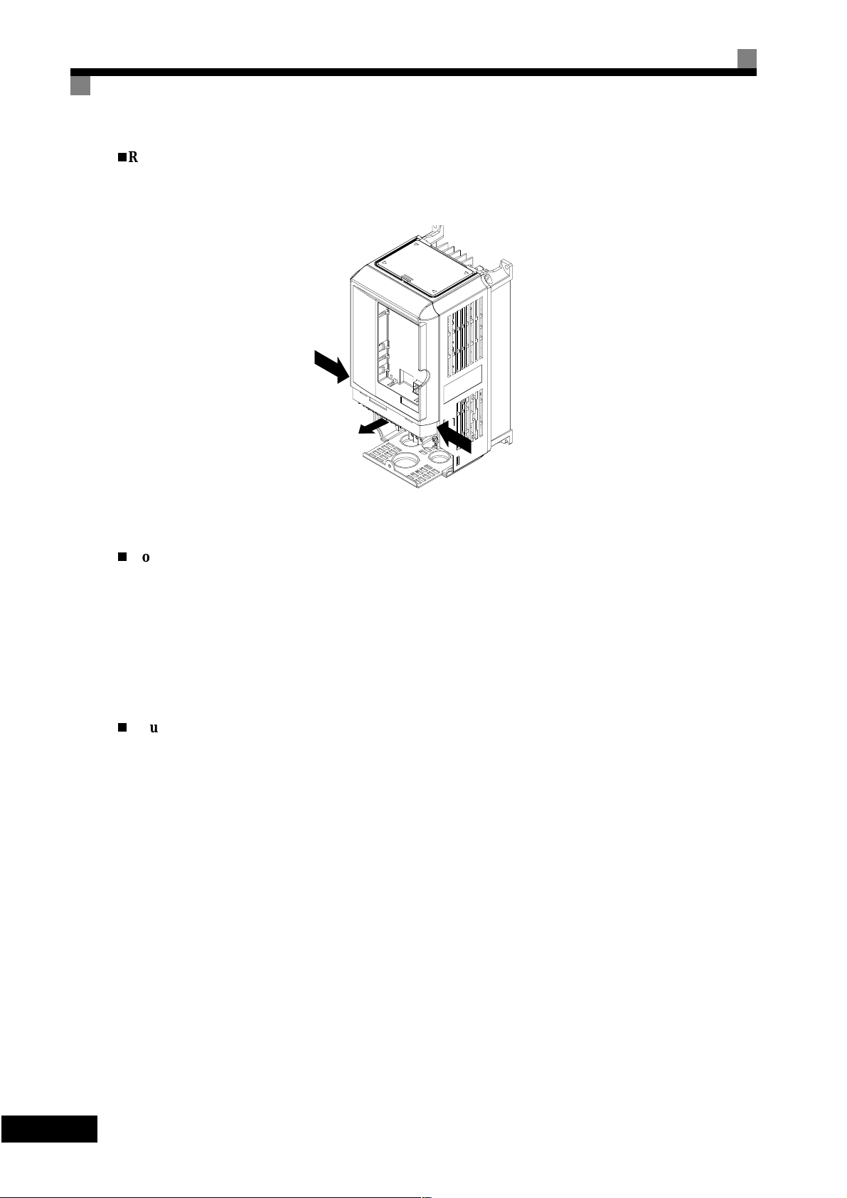
Removing the Front Cove r
Press the left and right sides of the front cover in the directions of arrows 1 and lift the bottom of the cover in
the direction of arrow 2 to remove the front cover as shown in the following illustration.
1
2
Fig 1.13 Removing the Front Cover (Model 3G3PV-A4055-E Shown Above)
Mounting the Front Cover
After wiring the terminals, mount the fron t cover to the Inverter b y performing the steps to rem ove the front
cover in reverse order.
1. Do not mount the front cover with the Digital Operator attached to the front cover; otherwise, Digital
Operator may malfunction due to imperfect contact.
2. Insert the tab of the upper part of the front cover into the groo ve of th e Inverter and press the lower part of
the front cover onto the Inverter until the front cover snaps shut.
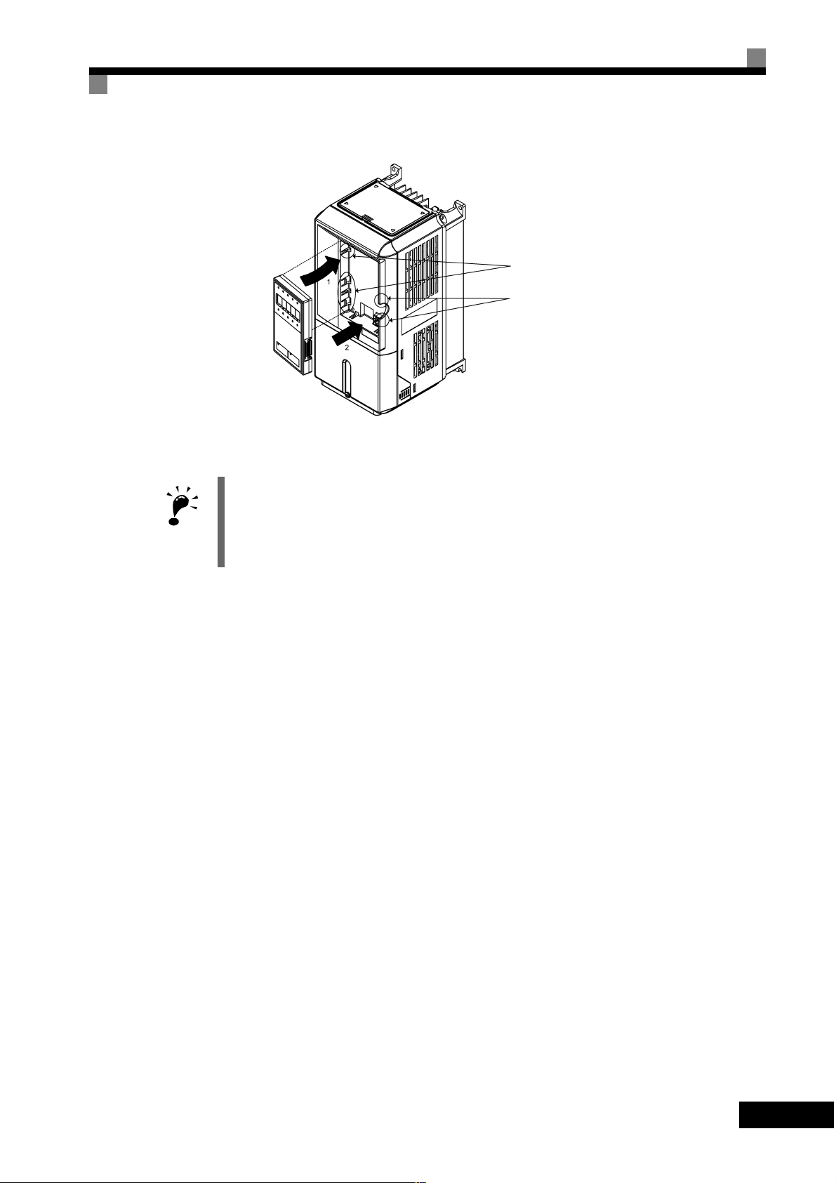
Mounting the Digital O perator
After attaching the terminal cover, mount the Digital Operator onto the Inverter using the following procedure.
1. Hook the Digital Operator at A (two locations) on the front cover in the direction of arrow 1 as shown in
the following illustration.
2. Press the Digital Operator in the direction of arrow 2 until it snaps in place at B (two locations).
-14
1
Page 29
Removing/Attaching the Digital Operator and Front Cover
Fig 1.14 Mounting the Digital Operator
A
B
IMPORTANT
1. Do not remo ve or attach the Digital O perator or mount or remove the front cover using method s other
than those described above, otherwise the Inverter may break or malfunction due to imperfect contact.
2. Never attach the front cover to the Inverter with the Digital Operator attached to the front cover. Imperfect
contact can result.
Always attach the front cover to the Inverter by itself first and then attach the Digital Operator to the front
cover.
1
-
15
Page 30
Inverters of 22 kW or More
For Inverters with an output of 22 kW or mor e, remove the terminal cover and then use the following procedures to remove the Digital Operator and main cover.
Removing the Digital Operator
Use the same procedure as for Inverters wi th an output of 18.5 kW or less .
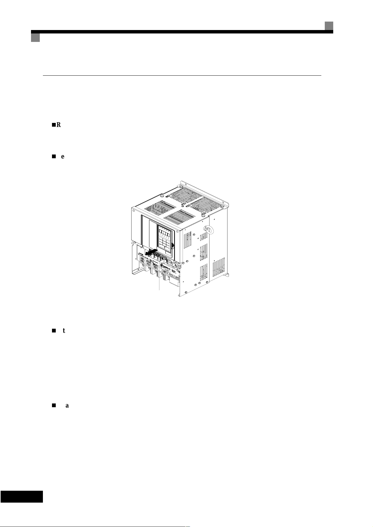
Removing the Front Cove r
Lift up at the location label 1 at the top of the control circuit terminal card in the direction of arrow 2.
2
1
Fig 1.15 Removing the Front Cover (Model 3G3PV-B2220-E Shown Above)
Attaching the Front Cover
After completing required work, such as mounting an optional card or setting the terminal card, attach the
front cover by reversing the procedure to remove it.
1. Confirm that the Digital Operator is not mounted on the front cover. Contact faults can occur if the cover is
attached while the Digital Operator is mounted to it.
2. Insert the tab on the top of the front cover into the slot on the Inverter and pr ess in on the cover until it
clicks into place on the Inverter.
Attaching the Digital Operator
Use the same procedure as for Inverters wi th an output of 18.5 kW or less .
-16
1
Page 31

2
Chapter 2
Wiring
This chapter describes wiring terminals, main circuit terminal connections, main c ircuit terminal wiring specifications, control circuit terminals and control circuit wiring specifications.
Wiring....................................................................................2-2
Connections to Peripheral Devices........................................2-3
Connection Diagram..............................................................2-4
Terminal Block Configuration...............................................2-6
Wiring Main Circuit Terminals .............................................2-7
Wiring Control Circuit Terminals........................................2-22
Wiring Check.......................................................................2-29
Installing and W ir ing Op ti on Card s .................... ... .............2-30
Page 32

Wiring
WARNING
WARNING
WARNING
Required
Caution
Caution
Caution
Wiring must be performed only after turning OFF the power supply . No t doing
so may result in electrical shock.
Wiri ng must be per formed by authori zed per sonnel. N ot doing so may result in
electrical shock.
Be sure to confirm operation only after wiring the emergency stop circuit. Not
doing so may result in injury.
Always connect the ground terminals to a ground of 100 Ohm or less for 200V AC class or 10 Ohm or less for the 400-V class. Not connecting to a proper
ground may resul t in electrica l shock or fire.
Install external circuit breakers and take other safety measures against shortcircuiting in external wiring. Not doing so may result in fire.
Confirm that the rated input voltage of the Inverter is the same as the AC
power supply voltage. An incorrect power supply may result in fire, injury or
malfunction.
Connect the Braking Resistor or Braking Resistor Unit as specified in th e manual. Not doing so may result in fire.
Caution
Caution
Caution
Caution
Be sure to wire correctly and securely. Not doing so may result in injury or
damage to the product .
Be sure to firmly tighten the screws on the terminal block. Not doing so may
result in fire, injury or damage to the product.
Do not conne c t a n A C pow e r s our c e to the U,V,W output. Doi n g so may result
in damage to the product or malfunction.
Do not connect a load to the machine during auto-tuning. Not doing so may
result in equipment damage.
2
-2
Page 33

Connections to Peripheral Devices
Examples of connections between the Inverter and typical peripheral devices are shown in Fig 2.1.
Power supply
Molded-case
circuit breaker
or ground fault
interrupter
Magnetic contactor (MC)
AC reactor for power
factor improvement
Connections to P eripheral Devic es
Input noise filter
Inverter
Ground
Output noise filter
DC reactor for power
factor improvement
Motor
Ground
Fig 2.1 Example Connections to Peripheral Devices
2
-
3
Page 34

Connection Diagram
The connection diagram of the Inverter is shown in Fig 2.2.
When using the Digital Operator, the motor can be operated by wiring only the main circuits.
SKDVH SRZHU
WR 9
+]
0XOWLIXQFWLRQ DQDORJXH
RXWSXW WR 9
0XOWLIXQFWLRQ DQDORJXH
RXWSXW WR 9
2
Fig 2.2 Connection Diagram
-4
Page 35

Circuit Descriptions
Refer to the numbers indicated in the diagram on the previous page.
•
These circuits are hazardous and are separated from accessible surfaces by protective separation.
•
These circuits are separated from all other circuits by protective separation consisting of double and
reinforced insulation. These circuits may b e interconnected with SELV (or equivalent) or non-SELV
circuits, but not both.
Inverter supplied by four-wire-system source (neutral grounded)
•
These circuits are SELV (Safety Extra Low Voltage) circuits and are separated from all other circuits
by protective separation consisting of double and reinforced insulation. These circuits may only be
interconnected with other SELV (or equivalent) circuits. These circuits can be accessible or interconnected with other accessible SELV circuits.
Inverter supplied by three-wire-system source (ungrounded or corner grounded)
•
These circuits are not separated from hazardous circuits by protectiv e separation, but only with basic
insulation. These circuits cannot be accessed and must not be interconnected with any circuits which
are accessible, unless they are isolated from accessible circuits by supplemental insulation.
1. Control circuit terminals are arranged as shown below.
Connection Diagram
IMPORTANT
2. The output current capacity of the +V terminal is 20 mA.
3. Disable the stall prevent ion during dec eleration (set parameter L3-04 to 0) when using a Brak ing Resistor Unit. If this user parameter is not changed to disable stall prevention, the system may no t sto p wi thin
deceleration time.
4. Main circuit terminals are indicated with double circles and control circuit terminals are indicated with single circles.
5. Sequence input signals S1 to S7 are labeled for sequence connections (0 V common and sinking mode)
for no-voltage contacts or NPN transistors. These are the default settings .
For PNP transistor sequence connections (+24V common and sourcing mode) or to provide a 24-V
external power supply, refer to
6. The master speed frequency reference can set to input either a voltage (terminal A1) or current (terminal
A2) by changing the setting of parameter H3-13. The default setting is for a voltage reference input.
7. The mu lti-function analog output is a dedicated meter output for an analog frequency m eter, current
meter, voltmeter, wattmeter, etc. Do not use this output for feedback control or for any other control purpose.
8. DC reactors to im prove the inp ut pow er factor built into 200 V Clas s Inverters for 22 to 110 kW and 400
V Class Inverters for 22 to 160 kW. A DC reactor is thu s an option only for Inverters for 18.5 k W or less.
Remove the short bar when connecting a DC reactor to Inverters for 18.5 kW or less.
Set parameter L8-01 to 1 when using an optional braking resistor unit and braking unit. When using this,
a shutoff sequence for the power supply must be made using a thermal relay trip.
Table 2.11
.
2
-
5
Page 36

Terminal Block Configuration
The terminal arrangement for 200 V Class Inverters are shown in Fig 2.3 and Fig 2.4.
Fig 2.3 Terminal Arrangement (200 V/400 V Class Inverter for 0.4 kW shown above)
Control circuit terminals
Main circuit termina l s
Charge indicator
Ground terminal
Control
Control
circuit
circuit
terminals
terminals
Main
circuit
terminals
Fig 2.4 Terminal Arrangement (200 V/400 V Class Inverter for 22 kW)
Charge indicator
Ground terminal
2
-6
Page 37

Wiring Main Circuit Terminals
Wiring Main Circuit Terminals
Applicable Wire Sizes and Closed-loop Connector
Select the appropriate wires and crimp terminals from Table 2.1 to Table 2.3. Refer to users m anual
(I526-E1-
Inverter
Model
3G3PV-
A2004-E
A2007-E
A2015-E
A2022-E
A2037-E
A2055-E
) for wire sizes for Braking Resistor Units and Braking Units.
Table 2.1 200 V Class Wire Sizes
Terminal Symbol
R/L1, S/L2, T/L3, , 1, 2,
U/T1, V/T2, W/T3 M4 1.2 to 1.5
R/L1, S/L2, T/L3, , 1, 2,
U/T1, V/T2, W/T3
R/L1, S/L2, T/L3, , 1, 2,
U/T1, V/T2, W/T3
R/L1, S/L2, T/L3, , 1, 2,
U/T1, V/T2, W/T3
R/L1, S/L2, T/L3, , 1, 2,
U/T1, V/T2, W/T3
R/L1, S/L2, T/L3, , 1, 2,
U/T1, V/T2, W/T3
Termial
Screws
Tightening
Torque
(N•m)
M4 1.2 to 1.5
M4 1.2 to 1.5
M4 1.2 to 1.5
M4 1.2 to 1.5
M4 1.2 to 1.5
Possible
Wire Sizes
2
(AWG)
mm
2 to 5.5
(14 to 10)
2 to 5.5
(14 to 10)
2 to 5.5
(14 to 10)
2 to 5.5
(14 to 10)
3.5 to 5.5
(12 to 10)
5.5
(10)
Recom-
mended
Wire Size
2
mm
(AWG)
2
(14)
2
(14)
2
(14)
2
(14)
3.5
(12)
5.5
(10)
Wire Type
A2075-E
A2110-E
A2150-E
A2185-E
A2220-E
B2220-E
A2300-E
B2300-E
R/L1, S/L2, T/L3, , 1, 2,
U/T1, V/T2, W/T3
R/L1, S/L2, T/L3, , 1, 2,
U/T1, V/T2, W/T3
R/L1, S/L2, T/L3, , 1, 2, U/T1, V/T2,
W/T3
R/L1, S/L2, T/L3, , 1, 2, U/T1, V/T2,
W/T3
R/L1, S/L2, T/L3, , 1, U/T1, V/T2,
W/T3, R1/L11, S1/L21, T1/L31
3
R/L1, S/L2, T/L3, , 1 U/T1,
V/T2, W/T3, R1/L11, S1/L21, T1/L31
3
M5 2.5
M5 2.5
M6 4.0 to 5.0
M6 4.0 to 5.0
M8 9.0 to 10.0
M6 4.0 to 5.0
M8 9.0 to 10.0
M6 4.0 to 5.0
M8 9.0 to 10.0
M8 9.0 to 10.0
M6 4.0 to 5.0
M8 9.0 to 10.0
8 to 14
(8 to 6)
14 to 22
(6 to 4)
30 to 38
(4 to 2)
22
(4)
30 to 38
(3 to 2)
22
(4)
30 to 60
(3 to 1)
8 to 22
(8 to 4)
22 to 38
(4 to 2)
50 to 60
(1 to 1/0)
8 to 22
(8 to 4)
22 to 38
(4 to 2)
8
(8)
14
(6)
30
(4)
22
(4)
30
(3)
22
(4)
30
(3)
-
22
(4)
50
(1)
-
22
(4)
Power cables,
e.g., 600 V vinyl
power cables
2
-
7
Page 38

Inverter
Model
Terminal Symbol
3G3PV-
R/L1, S/L2, T/L3, , 1 U/T1,
V/T2, W/T3, R1/L11, S1/L21, T1/L31
A2370-E
3
B2370-E
r/l1, ∆/l2 M4 1.3 to 1.4
R/L1, S/L2, T/L3, , 1 U/T1,
V/T2, W/T3, R1/L11, S1/L21, T1/L31
A2450-E
3
B2450-E
∆
/l2 M4 1.3 to 1.4
r/l1,
R/L1, S/L2, T/L3, , 1
U/T1, V/T2, W/T3, R1/L11, S1/L21, T1/L31 M10 17.6 to 22.5
A2550-E
B2550-E
3
∆
/l2 M4 1.3 to 1.4
r/l1,
R/L1, S/L2, T/L3, , 1
U/T1, V/T2, W/T3, R1/L11, S1/L21, T1/L31 M10 17.6 to 22.5
A2750-E
B2750-E
3
∆
/l2 M4 1.3 to 1.4
r/l1,
R/L1, S/L2, T/L3, , 1
U/T1, V/T2, W/T3, R1/L11, S1/L21, T1/L31 M12 31.4 to 39.2
A2900-E
B2900-E
3
∆
/l2 M4 1.3 to 1.4
r/l1,
R/L1, S/L2, T/L3, , 1
B211K
U/T1, V/T2, W/T3, R1/L11, S1/L21, T1/L31 M12 31.4 to 39.2
3
∆
/l2 M4 1.3 to 1.4
r/l1,
* The wire thickness is set for copper wires at 75°C
Termial
Screws
Tightening
Torque
(N•m)
M10 17.6 to 22.5
M8 8.8 to 10.8
M10 17.6 to 22.5
M10 17.6 to 22.5
M8 8.8 to 10.8
M10 17.6 to 22.5
M12 31.4 to 39.2
M8 8.8 to 10.8
M10 17.6 to 22.5
M12 31.4 to 39.2
M8 8.8 to 10.8
M10 17.6 to 22.5
M12 31.4 to 39.2
M8 8.8 to 10.8
M12 31.4 to 39.2
M12 31.4 to 39.2
M8 8.8 to 10.8
M12 31.4 to 39.2
Possible
Wire Sizes
2
(AWG)
mm
Recom-
mended
Wire Size
mm
(AWG)
60 to 100
(2/0 to 4/0 )60(2/0)
5.5 to 22
(10 to 4)
30 to 60
(2 to 2/0)
0.5 to 5.5
(20 to 10)
1.25
(16)
80 to 100
(3/0 to 4/0 )80(3/0)
5.5 to 22
(10 to 4)
38 to 60
(1 to 2/0)
0.5 to 5.5
(20 to 10)
50 to 100
(1/0 to 4/0 )
100
(4/0)
1.25
(16)
50 × 2P
(1/0 × 2P)
100
(4/0)
5.5 to 60
(10 to 2/0)
30 to 60
(3 to 4/0)
0.5 to 5.5
(20 to 10)
80 to 125
(3/0 to 250 )
80 to 100
(3/0 to 4/0 )
(1/0)
1.25
(16)
80 × 2P
(3/0 × 2P)
80 × 2P
(3/0 × 2P)
5.5 to 60
(10 to 2/0)
100 to 200
(3/0 to 400 )
0.5 to 5.5
(20 to 10)
150 to 200
(250 to 400)
100 to 150
(4/0 to 300 )
100
(3/0)
1.25
(16)
150 × 2P
(250 × 2P)
100 × 2P
(4/0 × 2P)
5.5 to 60
(10 to 2/0)
60 to 150
(2/0 to 300 )
0.5 to 5.5
(20 to 10)
60 × 2P
(2/0 × 2P)
1.25
(16)
200 × 2P
200 to 325
(350 to 600)
or 50 × 4P
(350 × 2P
or 1/0 ×
2P)
150 × 2P
150 to 325
(300 to 600)
or 50 × 4P
(300 × 2P
or 1/0 ×
4P)
5.5 to 60
(10 to 2/0)
150
(300)
0.5 to 5.5
(20 to 10)
150 × 2P
(300 × 2P)
1.25
(16)
2
–
30
(2)
–
38
(1)
–
50
–
–
–
Wire Type
Power cables,
e.g., 600 V vinyl
power cables
2
-8
Page 39

Inverter
Model
3G3PV-
A4004-E
Table 2.2 400 V Class Wire Sizes
Terminal Symbol
R/L1, S/L2, T/L3, , 1, 2,
U/T1, V/T2, W/T3
Tightening
Termi-
nal
Screws
M4 1.2 to 1.5
Torque
(N•m)
Wiring Main Circuit Terminals
Possible
Wire Sizes
2
(AWG)
mm
2 to 5.5
(14 to 10)
Recom-
mended
Wire Size
2
mm
(AWG)
2
(14)
Wire Type
A4007-E
A4015-E
A4022-E
A4037-E
A4040-E
A4055-E
A4075-E
A4110-E
A4150-E
A4185-E
A4220-E
B4220-E
A4300-E
B4300-E
A4370-E
B4370-E
R/L1, S/L2, T/L3, , 1, 2,
U/T1, V/T2, W/T3
R/L1, S/L2, T/L3, , 1, 2,
U/T1, V/T2, W/T3
R/L1, S/L2, T/L3, , 1, 2,
U/T1, V/T2, W/T3
R/L1, S/L2, T/L3, , 1, 2,
U/T1, V/T2, W/T3
R/L1, S/L2, T/L3, , 1, 2,
U/T1, V/T2, W/T3
R/L1, S/L2, T/L3, , 1, 2,
U/T1, V/T2, W/T3
R/L1, S/L2, T/L3, , 1, 2,
U/T1, V/T2, W/T3
R/L1, S/L2, T/L3, , 1, 2,
U/T1, V/T2, W/T3
R/L1, S/L2, T/L3, , 1, 2,
U/T1, V/T2, W/T3
R/L1, S/L2, T/L3, , 1, 2, U/T1, V/T2,
W/T3
R/L1, S/L2, T/L3, , 1, 3, U/T1, V/T2,
W/T3, R1/L11, S1/L21, T1/L31
R/L1, S/L2, T/L3, , 1, 3, U/T1, V/T2,
W/T3, R1/L11, S1/L21, T1/L31
R/L1, S/L2, T/L3, , 1, U/T1, V/T2, W/
T3, R1/L11, S1/L21, T1/L31
3
M4 1.2 to 1.5
M4 1.2 to 1.5
M4 1.2 to 1.5
M4 1.2 to 1.5
M4
1.2 to 1.5
M4 1.2 to 1.5
M4 1.2 to 1.5
M5 2.5
M5 2.5
M5
(M6)
M6 4.0 to 5.0
M6 4.0 to 5.0
M6 4.0 to 5.0
M8 9.0 to 10.0
M6 4.0 to 5.0
M8 9.0 to 10.0
M8 9.0 to 10.0
M6 4.0 to 5.0
M8 9.0 to 10.0
2.5
(4.0 to 5.0)
2 to 5.5
(14 to 10)
2 to 5.5
(14 to 10)
2 to 5.5
(14 to 10)
2 to 5.5
(14 to 10)
2 to 5.5
(14 to 10)
3.5 to 5.5
(12 to 10)
2 to 5.5
(14 to 10)
5.5(10)
3.5 to 5.5
(12 to 10)
5.5 to 14
(10 to 6)
8 to 14
(8 to 6)
5.5 to 14
(10 to 6)
8 to 38
(8 to 2)
8 to 22
(8 to 4)
14 to 22
(6 to 4)
14 to 38
(6 to 2)
22
(4)
22 to 38
(4 to 2)
22 to 60
(4 to 1/0)
8 to 22
(8 to 4)
22 to 38
(4 to 2)
2
(14)
2
(14)
2
(14)
3.5
(12)
2
(14)
3.5
(12)
2
(14)
3.5
(12)
2
(14)
5.5
(10)
3.5
(12)
8
(8)
5.5
(10)
8
(8)
5.5
(10)
8
(8)
8
(8)
14
(6)
14
(6)
22
(4)
22
(4)
38
(2)
-
22
(4)
Power cables,
e.g., 600 V vinyl
power cables
2
-
9
Page 40

Inverter
Model
Terminal Symbol
3G3PV-
R/L1, S/L2, T/L3, , 1, U/T1, V/T2, W/
A4450-E
B4450-E
T3, R1/L11, S1/L21, T1/L31
3
R/L1, S/L2, T/L3, , 1, U/T1, V/T2,
A4550-E
B4550-E
W/T3, R1/L11, S1/L21, T1/L31
3
R/L1, S/L2, T/L3, , 1
U/T1, V/T2, W/T3, R1/L11, S1/L21, T1/L31 M10 17.6 to 22.5
A4750-E
B4750-E
3
r/l1, ∆200/
200, ∆400/l2400
l2
R/L1, S/L2, T/L3, , 1
U/T1, V/T2, W/T3, R1/L11, S1/L21, T1/L31 M10 17.6 to 22.5
A4900-E
B4900-E
3
r/l1, ∆200/
200, ∆400/l2400
l2
R/L1, S/L2, T/L3, , 1
U/T1, V/T2, W/T3, R1/L11, S1/L21, T1/L33 M12 31.4 to 39.2
A411K-E
B411K-E
3
r/l1, ∆200/
200, ∆400/l2400
l2
R/L1, S/L2, T/L3, , 1
U/T1, V/T2, W/T3, R1/L11, S1/L21, T1/L33 M12 31.4 to 39.2
A413K-E
3
B413K-E
r/l1, ∆200/
200, ∆400/l2400
l2
R/L1, S/L2, T/L3, , 1
U/T1, V/T2, W/T3, R1/L11, S1/L21, T1/L33 M12 31.4 to 39.2
A416K-E
B416K-E
* The wire thickness is set for copper wires at 75°C.
3
r/l1, ∆200/
200, ∆400/l2400
l2
Tightening
Termi-
nal
Screws
Torque
(N•m)
M8 9.0 to 10.0
M6 4.0 to 5.0
M8 9.0 to 10.0
M8 9.0 to 10.0
M6 4.0 to 5.0
M8 9.0 to 10.0
M12 31.4 to 39.2
M8 8.8 to 10.8
M12 31.4 to 39.2
M4 1.3 to 1.4
M12 31.4 to 39.2
M8 8.8 to 10.8
M12 31.4 to 39.2
M4 1.3 to 1.4
M12 31.4 to 39.2
M8 8.8 to 10.8
M12 31.4 to 39.2
M4 1.3 to 1.4
M12 31.4 to 39.2
M8 8.8 to 10.8
M12 31.4 to 39.2
M4 1.3 to 1.4
M12 31.4 to 39.2
M8 8.8 to 10.8
M12 31.4 to 39.2
M4 1.3 to 1.4
Possible
Wire Sizes
2
(AWG)
mm
Recom-
mended
Wire Size
mm
(AWG)
38 to 60
(2 to 1/0)
8 to 22
(8 to 4)
22 to 38
(4 to 2)
50 to 60
(1 to 1/0)
8 to 22
(8 to 4)
22 to 38
(4 to 2)
60 to 100
(2/0 to 4/0 )60(2/0)
50 to 100
(1/0 to 4/0 )50(1/0)
5.5 to 22
(10 to 4)
38 to 60
(2 to 2/0)
0.5 to 5.5
(20 to 10)
80 to 100
(3/0 to 4/0 )
(4/0)
80 to 100
(3/0 to 4/0 )
(4/0)
8 to 22
(8 to 4)
50 to 100
(1 to 4/0)
0.5 to 5.5
(20 to 10)
50 to 100
(1/0 to 4/0 )
50 to 100
(1/0 to 4/0 )
50
(1/0 × 2P)
50 × 2P
(1/0 × 2P)
8 to 60
(8 to 2/0)
60 to 150
(2/0 to 300 )
(2/0)
0.5 to 5.5
(20 to 10)
80 to 100
(3/0 to 4/0 )
60 to 100
(2/0 to 4/0 )
80 × 2P
(3/0 × 2P)
60 × 2P
(2/0 × 2P)
8 to 60
(8 to 2/0)
100 to 150
(4/0 to 300 )
(4/0)
0.5 to 5.5
(20 to 10)
100 to 200
(4/0 to 400 )
80 to 200
(3/0 to 400 )
100 × 2P
(4/0 × 2P)
80 × 2P
(3/0 × 2P)
80 to 60
(8 to 2/0)
50 to 150
(1/0 to 300 )
50 × 2P
(1/0 × 2P)
0.5 to 5.5
(20 to 10)
38
(2)
22
(4)
50
(1)
22
(4)
38
(2)
1.25
(16)
100
100
50
(1)
1.25
(16)
×
600
1.25
(16)
100
1.25
(16)
1.25
(16)
2
-
-
-
-
2P
-
-
-
Wire Type
Power cables,
e.g., 600 V vinyl
power cables
-10
2
Page 41

Table 2.3 Closed-loop Connector Sizes (JIS C2805) (200 V Class and 400 V Class)
Wire Thickness (mm2)
0.5
0.75
1.25
2
3.5/5.5
8
14
22
30/38 M8 38 to 8
50/60
80
100 100 to 10
100
150 150 to 12
200 200 to 12
325
Wiring Main Circuit Terminals
Terminal Screws Size
M3.5 1.25 to 3.5
M4 1.25 to 4
M3.5 1.25 to 3.5
M4 1.25 to 4
M3.5 1.25 to 3.5
M4 1.25 to 4
M3.5 2 to 3.5
M4 2 to 4
M5 2 to 5
M6 2 to 6
M8 2 to 8
M4 5.5 to 4
M5 5.5 to 5
M6 5.5 to 6
M8 5.5 to 8
M5 8 to 5
M6 8 to 6
M8 8 to 8
M6 14 to 6
M8 14 to 8
M6 22 to 6
M8 22 to 8
M8 60 to 8
M10 60 to 10
80 to 10
M10
100 to 12
M12
M12 x 2 325 to 12
M16 325 to 16
IMPORTANT
Determine the wire size for the main circuit so that line voltage drop is within 2% of the rate d voltage. Line
voltage drop is calculated as follows:
Line voltage drop (V) =
x wire resistance (W/km) x wire length (m) x current (A) x 10
3
-3
2
-
11
Page 42

Main Circuit Terminal Functions
Main circuit terminal functions are summarized according to terminal symbols in Table 2.4. Wire the termi-
nals correctl y fo r t he desired purposes .
Table 2.4 Main Circuit Terminal Functions (200 V Class and 400 V Class)
Purpose Terminal Symbol
R/L1, S/L2, T/L3
Main circuit power input
R1/L11, S1/L2 1, T1/L31
Inverter outputs U/T1, V/T2, W/T3
DC power input
1,
200 V Class 400 V Class
A2004-E to A2 900-E A4004-E to A416K-E
B2220-E to B211K-E B4220-E to B416K-E
A2220-E to A2 900-E A4220-E to A416K-E
B2220-E to B211K-E B4220-E to B416K-E
A2004-E to A2 900-E A4004-E to A416K-E
B2220-E to B211K-E B4220-E to B416K-E
A2004-E to A2 900-E A4004-E to A416K-E
B2220-E to B211K-E B4220-E to B416K-E
Model: 3G3PV-
DC reactor connection
Braking Unit connection
Ground
1, 2
3,
A2004-E to A2 185-E A4004-E to A4185-E
A2004-E to A2 900-E A4220-E to A416K-E
B2220-E to B211K-E B4220-E to B416K-E
A2004-E to A2 900-E A4004-E to A416K-E
B2220-E to B211K-E B4220-E to B416K-E
-12
2
Page 43

Main Circuit Configurations
The main circuit configurations of the Inverter are shown in Fig 2.5.
Ta ble 2.5 Inverter Main Circuit Configurat ions
200 V Class 400 V Class
3G3PV-A2004-E to A2185-E
Wiring Main Circuit Terminals
3G3PV-A4004-E to A4185-E
Power
supply
Control
circuits
3G3PV-A2220-E,A2300-E
3G3PV-B2220-E,B2300-E
Power
supply
Control
circuits
3G3PV-A2370-E to A2900-E
3G3PV-B2370-E to B211K-E
Power
supply
Control
circuits
3G3PV-A4220-E to A4550-E
3G3PV-B4220-E to B4550-E
Power
supply
Control
circuits
3G3PV-A4750-E to A416K-E
3G3PV-B4750-E to B416K- E
Power
supply
Note 1. Consult your OMRON representative before using 12-phase rectification.
Control
circuits
Power
supply
Control
circuits
2
-
13
Page 44

Standard Connection Diagrams
Standard Inverter connection diagrams are shown in Fig 2.5. These are the same for both 200 V Class and
400 V Class Inverters. The connections depend on the Inverter capacity.
3G3PV-A2004-E to A2185-E,A4004-E toA4185-E
DC reactor
(optional)
3-phase 200
VAC (40 0 VAC)
Be sure to remove the short-circuit bar before connecting the DC
reactor.
Braking Resistor
Unit (optional)
Braking Unit
(optional)
3G3PV-A2370-E to A2900-E
3G3PV-B2370-E to B211K-E
Braking Resisto r
Unit (optional)
Braking Unit
(optional)
3-phase
200 VAC
3G3PV-A2220-E, A2300-E, A4220-E to A4550-E
3G3PV-B2220-E, B2300-E, B4220-E to B4550-E
Braking Resisto r
Unit (optional)
Braking Unit
(optional)
3-phase 200 VAC
(400 VAC)
The DC reactor is built in.
3G3PV-A4750-E to A416K-E
3G3PV-B4750-E to B416K-E
Braking Resisto r
Unit (optional)
Braking Unit
(optional)
3-phase
400 VAC
-14
2
Control power is supplied internally from the main circuit DC power supply for all Inverter models.
Fig 2.5 Main Circuit Terminal Connections
Page 45

Wiring Main Circuit Terminals
Wiring the Main Cir cuits
This section describes wiring connections for the main circuit inputs and outputs.
Wiring Main Circuit Inputs
Observe the following precautions for the main circuit power supply input.
Installing a Molded-case Circuit Breaker
When connecting the power input terminals (R/L2, S/L2 and T/L3) and power supply via a mo lded-case circuit breaker (MCCB) observe that the circuit breaker is suitable for the Inverter.
•
Choose an MCCB with a capacity of 1.5 to 2 times the Inverter's rated current.
•
For the MCCB's time characteristics, be sure to consider the Inverter's overload protection (one minute at
120% of the rate d output current ).
•
If the same MCCB is to be used for more than one Inverter, or other devices, set up a sequence, that the
powersupply will be turned OFF by a fault output, as shown below.
Inverter
Power supply
Fault out-
put (NC)
* For 400-V class Inverters, connect a 400/200-V transformer.
Fig 2.6 MCCB Installation
Installing a Ground Fault Interrupter
Inverter outputs use high-speed switching, so high-frequency leakage current is generated . Therefore, at the
Inverter primary side, use a ground f ault interru pter to detec t only the le akage current in th e freque ncy range
that is hazardous to humans and exclude high-frequency leakage current.
•
For the special-purpose ground fault interrupter for Inverters, ch oose a gr ou nd fault interrupter with a sensitivity amperage of at least 10 mA per Inverter.
•
When using a general ground fault interrupter, choose a ground fault interrupter with a sens itivity amperage of 200 mA or more per Inverter and with an operating time of 0.1 s or more.
Installing a Magnetic Contactor
If the power supply for the main circuit is to be shut off during a sequence, a magnetic contactor can be used.
When a magnetic contactor is installed on the primary side of the main circuit to forcibly stop the Inverter,
however, the regenerative braking does not work and the Inverter will coast to stop.
•
The Inverter c an b e start ed a nd st oppe d by o penin g an d clos ing th e ma gnet ic c ontac tor o n th e pri mary si de.
Frequently opening and closing the magnetic contactor, however, may cause the Inverter to break down.
Start and stop the Inverter at most once every 30 minutes.
2
-
15
Page 46

•
When the Inverter is operated with the Digital Operator, automatic operation cannot be perfor med after
recovery from a power interruption.
•
If a Braking Unit and a Braking Resistor Unit are used, program the sequence so that the magnetic contactor is turned OFF by the contact of the Braking Resistor Unit's thermal overload relay.
Connecting Input Power Supply to the Terminal Block
Input power supply can be connected to any terminal R, S or T on the terminal block; the phase sequence o f
input power supply is irrelevant to the phase sequence.
Installing an AC Reactor
If the Inverter is connected to a large-capacity power transformer (600 kW or more) o r the phase advancing
capacitor is switched, an excessive peak current may flow through the input power circuit, causing the con verter unit to break down.
To prevent this, install an optional AC Reactor on the input side of the Inverter or a DC reactor to the DC reactor connection terminals (for units from 22 kW the DC reactor is standard).
This also improves the po wer factor on the power supply side.
Installing a Surge Absorber
Always use a surge absorber or diode for inductive loads near the Inverter. These inductive loads include magnetic contactors, electromagnetic relays, solenoid valves, solenoids and magnetic brakes.
Installing a Noise Filter on Power Supply Side
Install a noise filter to eliminate noise transmitted between the power line and the Inverter.
•
Correct Noise Filter Installation
Power supply
Noise
filter
Fig 2.7 Correct Power supply Noise Filter Installati on.
3G3PV
Inverter
Other
controllers
Use a special-purpose noise filter for Inverters.
Ordinary: 3G3EV-PLNFD
EMC compatible: 3G3RV-PFI
3G3IV-PFN
/
-16
2
Page 47

•
Incorrect Noise Filter Installation
Wiring Main Circuit Terminals
Power supply
Power supply
Wiring the Output Side of Main Circuit
Generalpurpose
noise filter
Generalpurpose
noise filter
Fig 2.8 Incorrect Powe r supply Noise filter Ins tallation.
3G3PV
Inverter
Other
controllers
3G3PV
Inverter
Other
controllers
Do not use general-purpose noise filters. No general
purpose noise filter can effectively suppress noise
generated from the Inver ter .
Observe the following precautions when wiring the main output circuits.
Connecting the Inverter and Motor
Connect output terminals U/T1, V/T2 and W/T3 to motor lead wires U, V and W, respectively.
Check that the motor rotates forward with the forward run command. Switch over any two of the output termi-
nals to each other and reconnect if the motor rotates in reverse with the forward run comm and.
Never Connect a Power Supply to Output Terminals
Never connect a power supply to output terminals U/T1, V/T2 and W/T3. If voltage is applied to the output
terminals, the internal circuits of the Inverter will be damaged.
Never Short or Ground Output Te rminals
If the output terminals are touched with bare hands or the output wires come into contact with the Inverter casing, an electric shock or grounding will occur. This is extremely hazardous. Do not short the output wires.
Do Not Use a Phase Advancing Capacitor or Noise Filter
Never connect a phase advancing capac itor or LC/RC noise filter to an output circuit. The high-fre quency
components of the Inverter output may result in overheating or damage to these part or may result in damage
to the Inverter or cause other parts to burn.
2
-
17
Page 48

Do Not Use an Electromagnetic Switch
Never connect an electromagnetic switch (MC) between the Inverter and motor and turn it ON or OFF during
operation. If the MC is turned ON while the Inverter is operating, a large inrush current will be caused and the
overcurrent protection in the Inverter will operate.
When using an MC to switch to a commercial power supply, stop the Inverter and motor before operating the
MC. Use the speed search function if the MC is operated during operation. If measures for mom entary powe r
interrupts are required, use a delayed release MC.
Installing a Thermal Overload Relay
This Inverter has an electronic thermal protection function to protect the motor from overheating. If, however,
more than one motor is operated with one Inverter or a multi-polar motor is used, always install a thermal
relay (THR) between the Inverter and the motor an d set L1-01 to 0 (no motor protection). The sequence
should be designed so that the contacts of the thermal overload relay turn OFF the magnetic contactor on the
main circuit inputs.
Installing a Noise Filter on Output Side
Connect a noise filter to the output side of the Inverter to reduce radio noise and inductive noise.
3G3PV 3G3IV-PLF
Noise
Filter
Radio noise
Powersupply
Inverter
Inductive noise
Signal line
Controller
Inductive noise: Electromagnetic induction generates noise on the signal line, causing the controller to malfunction.
Radio noise: Electromagnetic waves from the Inverter and cables cause the broadcasting radio receiver to make noise.
Fig 2.9 Installing a noise filter on the output side
AM radio
Countermeasures against Inductive Noise
As described previously, a noise filter can be used to prevent inductive noise from being generated on the output side. Alternatively, cables can be routed through a grounded metal pipe to prevent inductive noise. Keeping the metal pipe at least 30 cm away from the signal line considerably reduces inductive noise.
Metal pipe 3G3PV
Inverter
Power supply
30cm min.
Signal line
Controller
-18
2
Fig 2.10 Countermeasures against Inductive noise
Page 49

Wiring Main Circuit Terminals
Countermeasures Against Radio Interference
Radio noise is generated from the Inverter as well as from the input and output lines. To reduce radio noise,
install noise filters on both, input and output, sides and also install the Inverter in a totally enclosed steel box.
The cable between the Inverter and the motor should be as short as possible.
Noise
Filter
Power supply
Fig 2.11 Countermeasures against Radio Interference
Steel box
Inverter
Metal pipe
Noise
Filter
Cable Length between Inverter and Motor
If the cable between the Inverter and the motor is long, the high-frequency leakage current will increase, causing the Inverter output current to increase as well. This may affect peripheral devices. To prevent this, adjust
the carrier f reque ncy (set in C 6-01, C6-0 2) as show n in Table 2.6. (For details, refer to Chapter 5 Parameter
Tables.)
Table 2.6 Cable Length between Inverter and Motor
Cable length 50 m max. 100 m max. More than 100 m
Carrier frequency 15 kHz max. 10 kHz max. 5 kHz max.
Ground Wiring
Observe the following precautions when wiring the ground line.
•
Always use the grou nd t e r mina l of t he 20 0 V Inv e rte r with a gr ou nd re sist ance of less than 100 W and t ha t
of the 400 V Inverter with a ground resistance of l ess than 10 W.
•
Do not share the ground wire with other devices, such as welding machines or power tools.
•
Always use a ground wire that complies with technical standards on electrical equipment and minimize the
length of the ground wire.
Leakage current flows through the Inverter. Therefore, if the distance between the ground electrode and
the ground terminal is too long, potential on the ground terminal of the Inverter will become unstable.
•
When using more than one Inverter, be careful not to loop the ground wire.
OK
NO
Fig 2.12 Ground Wiring
2
-
19
Page 50

Connecting an optional Braking Resistor Unit (3G 3IV-PLKB) and Braking Unit (3G3IV-
PCDBR)
Connect the Braking Resistor Unit and Braking Unit to the Inverter as shown in the Fig 2.13.
To prevent the Unit from overheating, design the sequence to turn OFF the power supply for the thermal over-
load relay trip contacts of the Unit as shown in Fig 2.13.
200 V and 400 V Class Inverters with 0.4 to 18.5 kW Output
3G3IV-PCDBR Braking
Unit
1
Inverter
Thermal overload
relay trip contact
3G3IV-PLKB
Braking Resistor Unit
200 V and 400 V Class Inverters with 22 kW or higher Output
3G3IV-PCDBR Braking
Unit
Inverter
3G3IV-PLKB
Braking Resistor
Unit
Thermal protector
trip contact
Thermal protector
trip contact
-20
2
Thermal overload
relay trip contact
Fig 2.13 Connecting the Braking Resistor Unit and Braking Unit
When using an optional Braking Unit and Braking Resistor Unit, the param ete r L3-04 (St all prev ent ion
selection during deceleration) has to be set to 0. Otherwise stall prevention is enabled and the Braking Unit
will not work.
IMPORTANT
Page 51

Wiring Main Circuit Terminals
Connecting Braking Units in Parallel
When connecting two or more Braking Units in parallel, use the wiring and connectors shown in Fig 2.14.
There are connectors for selecting wh ether each Braking Unit is to be a Master or Slave. Select “Master” for
the first Braking Unit only and select “Slave” for all other Braking Units (i.e., from the second Unit onwards).
Braking resistor overheating contacts (Thermal protector contacts)
Braking
Resistor
Unit
Braking resistor ove rheating contacts (Thermal protector contacts)
Braking
Resistor
Unit
Braking resist or overheating contacts (Thermal protector contacts)
Inverter
Level
detector
Braking Unit #2
Braking Unit #3
Braking Unit #1
Cooling fin overheating contacts (thermostat contacts)
Cooling fin overheating contacts (ther m ostatic contacts)
Cooling fin overheating contacts (thermostatic contacts)
Fig 2.14 Connecting Braking Units in Parallel
Breaking Unit Application Precautions
When using a Braking Resistor Unit, create a sequence to detect overheating of the braking resistor.
Braking
Resistor
Unit
2
-
21
Page 52

Wiring Control Circuit Terminals
Wire Si zes
For remote operation using analog signals, keep the control line length between the Analog Operato r or operation signals and the Inverter to 50 m or less and separate the lines from high-power lines (main circuits or
relay sequence circuits) to reduce induction from peripheral d evices.
When setting frequencies from an external frequency setter (and not from a Digital Operat or), used shielded
twisted-pair wires and ground the shield to terminal E (G), as shown in the following diagram.
E (G)
Shield terminal
2 k
Ω
Speed setting power supply, +15 V 20 mA
Master speed reference, 0 to +10 V (20 kΩ)
Master speed reference, 4 to 20 mA (250 Ω)/0 to +10 V (20 kΩ)
Fig 2.15
External
frequency
reference
2 k
Ω
0 to +10 V
4 to 20 mA
Terminal numbers and wire sizes are shown in Table 2.7.
Table 2.7 Terminal Numbers and Wire Sizes
*2
*3
:
Recom-
mended
Wire Size
2
(AWG)
mm
0.75
(18)
1.25
(12)
Wire Type
• Shielded, twisted-pair wire
• Shielded, polyethylene-cov-
ered, vinyl sheath cable
(KPEV-S by Hitachi Electri cal
Wire or equivalent)
Termi-
Terminals
FM, AC, AM, SC, A1,
A2, +V, –V, SN, SC, SP,
S1, S2, S3, S4, S5, S6,
S7, MA, MB, MC, M1,
M2, M3, M4
R+, R-, S+, S-, IG
E (G) M3.5 0.8 to 1.0
* 1. Use shielded twisted-pair cables to input an external frequency reference.
* 2. Refer to Table 2.3 Close-loop Connector Sizes (JIS C2805, 200-V and 400-V class) for suitable closed-loop crimp terminal sizes for the wires.
* 3. We recommend using straight solderless term inal on signal lines to simplify wiring and improve reliability.
nal
Screws
Phoenix
type
Tightening
Torque
(N•m)
0.5 to 0.6
Possible
Wire Sizes
2
mm
(AWG)
Single wire
0.14 to 2.5
Stranded
wire:
0.14 to 1.5
(26 to 14)
0.5 to 2
(20 to 14)
*1
-22
2
Page 53

Straight Solderless Terminals for Signal Lines
Models and sizes of straight solderless terminal are shown in the following table.
Table 2.8 Straight Solderless Terminal Sizes
Wiring Control Circuit Terminals
Wire Size mm2 (AWG)
0.25 (24) AI 0.25 - 8YE 0.8 2 12.5
0.5 (20) AI 0.5 - 8WH 1.1 2.5 14
0.75 (18) AI 0.75 - 8GY 1.3 2.8 14
1.25 (16) AI 1.5 - 8BK 1.8 3.4 14
2 (14) AI 2.5 - 8BU 2.3 4.2 14
Wiring Method
Model d1 d2 L Manufacturer
Fig 2.16 Straight Solderless Terminal Sizes
Use the following procedure to connect wires to the terminal block.
Phoenix Contact
L
1. Loosen the terminal screws with a thin-slot screwdriver.
2. Inser t the wires from underneath th e terminal block.
3. Tighten the terminal screws firmly.
Thin-slot screwdriver
Control circuit
terminal block
Strip the end for
7 mm if no solderless terminal
is used.
Wires
Solderless terminal or wire
without soldering
Fig 2.17 Connecting Wires to Terminal Block
Blade of screwdriver
3.5 mm max.
Blade thickness: 0.6 mm max.
2
-
23
Page 54

Control Circuit Terminal Functions
The functions of the control circuit terminals are shown in T abl e 2.9. Use the appropriate terminals for the correct purposes.
Table 2.9 Contro l Circuit Terminals
Type
No. Signal Name Function Signal Level
S1 Forward run/stop command Forward run when ON; stopped when OFF.
S2 Reverse run/stop command Reverse run when ON; stopped when OFF.
*1
Fault when ON.
Reset when ON
Auxiliary frequency reference when ON.
Multi-step setting 2 when
Functions are
selected by setting H1-01 to
H1-05.
24 VDC, 8 mA
Photo coupler isolatio n
ON.
*1
Jog frequency when ON.
15 V
(Max. current: 20 mA)
–15 V
(Max. current: 20 mA)
4 to 20 mA/100%
0 to +10 V/100%
Function is
selected by setting H3-09.
4 to 20 mA(250Ω)
0 to +10 V(20kΩ)
––
Se-
quence
input
signals
Analog
input
signals
S3
External fault input
S4
Fault reset
*
Multi-step speed reference
*1
S5
1
(Master/auxiliary switch)
Multi-step speed reference
S6
*1
2
S7
Jog frequency reference
SC Sequence input common ––
+V 15 V power output 15 V power supply for analog references
–V –15 V power output not used
A1 Frequency reference 0 to +1 0 V/100% 0 to +10 V(20 kΩ)
A2 Multi-function analog input
AC Analog reference common ––
Shield wire, optional ground
E(G)
line connection point
M1
Sequence
output
signals
Analog
output
signals
RS-
485/
422
Running signal
(1NO contact)
M2
M3
Zero speed
M4
MA
MB
Fault output signal (SPDT)
MC
Multi-function analog output
FM
(frequency output)
AC Analog common (copy) –
Multi-function analog output
AM
(current monitor)
R+
communications input
RS+
communications output
S-
Operating when ON.
Multi-function
contact outputs
Zero level (b2-01) or
below when ON
Fault when CLOSED across MA and MC
Fault when OPEN across MB and MC
0 to +10 V/100% frequency
5 V/Inverter's rated current
Multi-function
analog monitor 1
Multi-function
analog monitor 2
For 2-wire RS-485, short R+ and S+ as well
as R- and S-.
Dry contacts
Contact capacity:
1 A max. at 250 VAC
1 A max. at 30 VDC
Dry contacts
Contact capacity:
1 A max. at 250 VAC
1 A max. at 30 VDC
0 to +10 V max. ±5%
2 mA max.
Differential input, PHC
isolation
Differential input, PHC
isolation
IG Signal common - -
* 1. The default settin g s ar e g iven for terminal s S3 to S7. For a 3- wi re se quence, the defaul t settings are a 3- wire sequence for S5, multi-step speed setting 1
for S6 and multi-step speed setting 2 for S7.
-24
2
Page 55

Wiring Control Circuit Terminals
DIP Switch S1 and Shunt Connector CN15
The DIP switch S1 and shunt connector CN 15 of the optional terminal board (3G3PV-PETC618120) are
described in this section.
S1
Terminating resistance*
OFF
ON
I
V
Analog input A2 switch
: Factory settings
CN15
Analog output switch**
Voltage output
Current output
S1
CN15
* Note: Refer to
**Note: CN15 is not available at the standard terminal board.
Table 2.10
An optional terminal board with CN15 Shunt Connector is available.
The standard setting is voltage output.
for S1 functions.
Fig 2.18 DIP Switch S1 and Shunt Connector CN15
The functions of DIP switch S1 are shown in the following table.
Table 2.10 DIP Switch S1
Name Function Setting
S1-1
RS-485 and RS-422 terminating resistance
S1-2 Input method for analog input A2
Sinking/Sourcing Mode
OFF: No terminating resistance
ON: Ter mi nating resistance of 110
Ω
OFF: 0 to 10 V (internal resistance: 20 kΩ)
ON: 4 to 20 mA (internal resistance: 250 Ω)
The input terminal logic can be switched between sinking mode (0-V common) and sourcing mode (+24V
common) by using the terminals SN, SC and SP. An external power supply is also supported, providing more
freedom in signal input methods.
2
-
25
Page 56

Table 2.11 Sinking/Sourcing Mode and Input Signals
Internal Power Supply – Sinking Mode
Internal Power Supply – Sourcing Mode
External Power Supply – Sinking Mo de
External Powe r Supply – Sourcing Mode
-26
2
Page 57

Control Circuit Terminal Connections
Connections to Inverter control circuit terminals are shown in Fig 2.19.
Optional
Wiring Control Circuit Terminals
FM
Multi-function analog
output 1
Multi-function analog
output 2
AM
Fig 2.19 Control Circuit Terminal Connections
2
-
27
Page 58

Control Circuit Wiring Precautions
Observe the following precautions when wiring control circuits.
•
Separate control circuit wiring from main circuit wiring (te rminals R/L1, S/L 2, T/L3, U/T1, V/T2 , W/T3,
, 1, 2 and 3) and other high-power lines.
•
Separate wiring for control circuit term inals MA, MB, MC, M1, M2, M3 and M4 (contact outputs) from
wiring to other control circuit terminals.
•
If using an optional external power supply, it shall be a UL Listed Class 2 power supply source.
•
Use twisted-pair or shielded twisted-pair cables for control circuits to prevent operating faults. Process
cable ends as shown in Fig 2.20.
•
Connect the shield wire to terminal E (G).
•
Insulate the shield with tape to prevent contact with other signal lines and equipment.
Shield sheath
Connect to shield sheath terminal at Inverter (terminal E
(G))
Fig 2.20 Processing the Ends of Twisted-pair Cables
Armor
Do not connect here.
Insulate with tape
-28
2
Page 59

Wiring Check
Checks
Check all wiring after wiring has been completed. Do not perform a buzzer check on cont rol circuits. Perform
the following checks on the wiring.
•
Is all wiring correct?
•
Have any wire clippings, screws or other foreign material been left?
•
Are all screws tight?
•
Are any wire ends contacting other terminals?
Wiring Check
2
-
29
Page 60

Installing and Wiring Option Cards
Option Card Models and Specifications
One Option Card can be mounted in the Inverter as shown in Fig 2.21.
Table 2.12 lists the type of Option Cards and their specifications.
Table 2.12 Option Card and their Specificat ions
Card Model Specifications
Device Net Communications
Card
Installation
Before mounting an Option Card, remove the terminal cover and be sure that the charge indicator inside the
Inverter is not lit. After confirming th at the charge indicator is not lit, rem ove the Digital Operato r and front
cover and then mount the Option Card.
Refer to documentation provided with the Option Card for actual mounting instructions for option slot C.
3G3FVPDRT1-SIN
Deficient communications support C
Mounting Lo ca-
tion
Preventing C Option Card Connectors from Rising
After installing an Option Card into slot C, insert an Option Clip to prevent the side with the connector from
rising. The Option Clip can be easily removed by holding onto the protruding portion of the Clip and pulling it
out.
CN2
C Option Card connector
C Option Card mounting spacer
Option clip
(to prevent raising of
C Option Card)
C Option Card
-30
2
Fig 2.21
Mounting Option Cards
Page 61

3
Chapter 3
Digital Operator and
Modes
This chapter describes Digital Oper ator displays and functi ons and provides an over view of
operating modes and switching between modes.
Digital Operator.....................................................................3-2
Modes....................................................................................3-5
Page 62

Digital Operator
This section describes the displays and functions of the Digital Operator.The key names and functions of
the Digital Operator are described below.
Digital Operator with LED Display (3G3IV-PJVOP161)
Drive Mode Indicators
FWD: Lit when there is a forward run command
REV: Lit when there is a reverse run command
SEQ: Lit when the run command from the control
REF: Lit when the frequency reference from con trol
ALARM:Lit when an error or alarm has occurred.
Data Display
Displays monitor data, parameter numbers and
settings.
Mode Display
DRIVE: Lit in Drive Mode.
QUICK: Lit in Quick Programming Mode.
ADV: Lit in Advanced Programming Mode.
VERIFY: Lit in Verify Mode.
AUTO : Lit in Autotuning Mode.
TUNING
Keys
Execute operations such as setting us er parameters, monitoring, jogging and autotuning.
input.
input.
circuit terminal is enabled.
circuit terminals A1 and A2 is enabled.
Digital Operator with LCD Display (3G3IV-PJVOP160)
Drive Mode Indicators
FWD:Lit when there is a forward run command
input.
REV: Lit when there is a reverse run command
input.
SEQ:Lit when the run command from the control
circuit terminal is enabled.
REF:Lit when the frequency reference from control
circuit terminals A1 and A2 is enabled.
Data Display
Keys
ALARM:Lit when an error or alarm has occurred.
Displays monitor data, parameter numbers and
settings.
Execute operations such as setting user parameters, monitoring, jogging and autotuning.
3
Fig 3.1 Digital Operator Component Names and Functions
-2
Page 63

Digital Operator Keys
The names and functions of the Digital Operator Keys are described in Table 3.1.
Table 3.1 Key Functions
Key Name Function
Switches between operation via the Digital Operator (LOCAL) and
LOCAL/REMOTE Key
MENU Key Selects menu items (modes).
ESC Key Returns to the status before the DATA/ENTER Key was pr essed.
control circuit terminal operation (REMOTE).
This Key can be enabled or disabled by setting user parameter o2-01.
Digital Operator
JOG Key
FWD/REV Key
Digit Selection/RESET Key
Increment Key
Decrement Key
ENTER Key
Enables jog operation when the Inverter is being operated from the
Digital Operator.
Selects the rotation direction of the motor when the Inverter is being
operated from the Digital Operator.
Sets the number of digits for user par am ete r setti ngs.
Also acts as the Reset key when a fault has occurred.
Selects menu items, sets user parameter numbers and increments set
values.
Used to move to the next item or data.
Selects menu items, sets user parameter numbers and decrements set
values.
Used to move to the previous item or data.
Pressed to enter menu items, user parameters and set values.
Also used to switch from one screen to another.
RUN Key
STOP Key
Note Except in diagrams, Keys are referred to using the Key names listed in the above table.
Starts the Inverter operation when the Inverter is being controlled by
the Digital Operator.
Stops Inverter operation.
This Key can be enable d or disa bled w hen op eratin g from the con trol
circuit terminal by setting user parameter o2-02.
3
-
3
Page 64

There are indicators on the upper left of the RUN and STOP Keys on the Digital Opera tor. These indicators
will light and flash to indicate operating status.
The RUN Key indicator will flash and the STOP Key indicator will light during initial excitation of the
dynamic brake. The relationship between the indicators on the RUN and STOP Keys and the Inverter status is
shown in the Fig 3.2.
Fig 3.2 RUN and STOP Indicators
3
-4
Page 65

Modes
This section describes the Inverter's modes and switching between modes.
Inverter Mod es
The Inverter's user parameters and monitoring functions are organized in groups called modes that make it
easier to read and set user parameters.The Inverter is equipped with 5 modes.
The 5 modes and their primary functions are shown in the Table 3.2.
Table 3.2 Modes
Mode Primary function(s)
The Inverter can be run in this mode.
Drive mode
Quick program m ing mode
Advanced programming mode Use this mode to reference and set all user parameters.
Verify mode
Autotuning mode*
Use this mode when monitoring values such as frequency references or output current, displaying fault information or displaying the fault history.
Use this mode to reference and set the minimum user parameters to operate the
Inverter (e.g., the operating environment of the Inverter and Digital Operator).
Use this mode to read/set user parameters that have been changed from their factory-set values.
Use this mode when running a motor with unknown motor parameters in the vector
control mode. The motor parameters are calculated and set automatically.
This mode can also be used to measure only the motor line-to-line resistance.
Modes
*Always perform autotuning with the motor before operating using vector control. Autotuning Mode will not be displayed during operation or when an
error has occurred.
3
-
5
Page 66

Switching Modes
The mode selection display will appear when the MENU key is pressed from a monitor or setting display.
Press the MENU key from the mode selection display to switch between the modes.
Press the ENTER key from the mode selection key to monitor data and from a monito r display to access the
setting display.
Power ON
Drive Mode
(Operation possible)
Quick
Programming Mode
Advanced
Programming Mode
Verify Mode
Autotuning
Mode
Mode Selection Displays Monitor Displays Setting Displays
Lit
If a user constant is changed
the number will be displayed.
Flashing
Fig 3.3 Mode Transitions
Not lit
When returning from a setting
display, the right most digit
of the monitor display will
flash.
3
-6
Page 67

Drive Mode
Drive mode is the mode in which the Inverter can be operated. The following monitor displays are possible in
drive mode: The frequency reference, output frequency, output current and output voltage, as well as fault
information and the fault history.
When b1-01 (Reference selection) is set to 0, the fr equency can be changed from the f requency setting display. Use the Increment, Decrement and Digit Selection/RESET keys to change the frequency. The user
ENTER
parameter will be written a nd the monitor display will be returned to when the
changing the setting.
Example Operations
Key operations in drive mode are shown in the following figure.
key is pressed after
Modes
IMPORTANT
Fig 3.4 Operations in Drive Mode
The display for the first monitor parameter (frequenc y reference) will be displayed when power is turned
ON. The monitor item displayed at startup can be set in o1-02 (Monitor Selection after Power Up).
Operation cannot be started from the mode selection display.
3
-
7
Page 68

Quick Programming Mode
In quick programming mode, the parameters required for Inverter trial operation can be monitored and set.
parameters can be changed from the setting displays. Use the Increment, Decrement and Digit Selection/
RESET keys to change the frequency. The user parameter will be written and th e monitor display will be
returned to when the ENTER key is pressed after changing the setting.
Refer to Chapter 5 Parameters for details on the parameters displayed in Quick Programming Mode.
Example Operations
Key operations in quick programming mode are shown in the following figure.
Mode Selection Display Monitor display Setting Display
Reference selectionQuick Programming Mode
Operation Method select ion
Stopping Method selection
3
Terminal FM Gain
Terminal AM Gain
Motor Protection selection
Decelaration stall selection
Fig 3.5 Operations in Quick Programming Mode
-8
Page 69

Advanced Programming Mode
In advanced programming mode, all Inverter parameters c an be monitore d a nd set.
parameters can be changed from the setting displays. Use the Increment, Decrement and Digit Selection/
RESET keys to change the frequency. The user parameter will be written and the display will return to monitor display when the ENTER key is pressed after changing the setting.
Refer to Chapter 5 Parameters for details on the parameters.
Example Operations
Key operations in advanced programming mode are shown in the following figure.
Mode Selection display Function Selection Display Monitor Display Setting Display
Setup settingsAdvanced Programming Mode Language
Modes
Access level
Initialize
PI controlbox: b5-xx PI Control m ode selection
Proportional Gain
PI feedback command
loss detection time
Copy functions: o3-xx
Copy function selection
Read permitted selection
Fig 3.6 Operations in Advanced Programming Mode
3
-
9
Page 70

Setting Parameters
Here, the procedure is sh own to change C 1-01 (Accele ration Time 1) from 10 s to 20 s.
Table 3.3 Setting User parameters in Advanced Programming Mode
Step
No.
1 Power supply turned ON.
2 MENU Key pressed to enter drive mode.
3
Digital Operator Display Description
MENU Key pressed to enter quick programming mode.
4
5 ENTER pressed to access monitor display.
6
7
8
9
MENU Key pressed to enter advanced programming mode.
Increment or Decrement Key pressed to display C1-01 (Acceleration Time 1).
ENTER Key pressed to access setting display.
The setting of C1-01 (10.00) is displayed.
Digit Selection/RESET
move the flashing digit to the right.
Increment Key pressed to change set value to
20.00 s.
Key pressed to
-10
3
ENTER Key pressed to enter the set data.
10
11 The monitor display for C1-01 returns.
“END” is displayed for 10 s and then the
entered value is displayed for 0.5 s.
Page 71

Verify Mode
Verify mode is used to display any parameters that have been changed from their default settings in a programming mode or by autotuning. “None” will be displayed if no settings have been changed.
Even in verify mode, the same procedures can be used to change settings as they are used in the programming
modes. Use the Increment, Decrement and Digit Sele ction/RESET keys to change the frequency. The user
parameter will be written and the monitor display will b e returned to when the ENTER key is pressed af ter
changing the setting.
Example Operations
An example of key operations is given below for whe n the following settings have been changed from their
default settings: b1-01 (Reference Selection), C1-01 (Acceleration Time 1), E1-01 (Input Voltage Setting) and
E2-01 (Motor Rated Curr e nt ) .
Modes
Mode Selection Display
Verify Mode
Monitor Display
Frequency reference
selection
Acceleration time 1
Input voltage setting
Motor rated current
Setting Displ ay
Frequency reference
selection
Acceleration time 1
Input voltag e setting
Motor rated current
Fig 3.7 Operations in Verify Mode
3
-
11
Page 72

Autotuning Mode
Autotuning automatically tunes and sets the required motorparameters when operating in the open-loo p or
flux vector control modes. Always perform autotuning before starting operation.
When the motor can not be disconnected from the load, perform stationary autotuning. Contact y our dealer to
set motorparameters by calculation.
The Inverter ’s autotunin g function automatically determines the motor parameters, while a servo system’s
autotuning function determines the size of a load, so these autotunig functions are fundamentally different.
Example of Operation
Set the motor output power (in kW) and ra ted c urrent specif ied on the namep late on the m otor a nd then press
the RUN key. The motor is automatically run and the motor line-to-line resistance measured based on these
settings will be set.
Always set the above items. Autotuning cannot be started otherwise.
Parameters can be changed from the setting display s. Use the Increment, Decrement and D igit Selection/
RESET keys to change the frequency. The parameter will be written and the display will be returned to monitor display when the ENTER key is pressed after changing the setting.
Autotuning
Autotuning Monitor Display
Motor output power
Motor rated curr en t
Autotuni n g start*
Fig 3.8 Operation in Autotuning Mode
If a fault occurs during autotuning, refer to
Chapter 7 .
Setting Display
Motor output power
Motor rated current
Autotuning
Stop command input
Autotuning completed
-12
3
IMPORTANT
Page 73

4
Chapter 4
Trial Operation
This chapter describes the procedures for trial operation of the Inverter and provides an example
of trial operation.
Trial Operation Flowchart.....................................................4-3
Trial Operation Procedures....................................................4-4
Adjustment Suggestions......................................................4-13
Page 74

Cautions and warnings
Turn ON the input power supply only after mounting the front cover, terminal
WARNING
WARNING
covers, bottom cover, Operator and optional items. Not doing so may result in
electrical shock.
Do not remove the front cover, terminal covers, bottom cover, Operator or
optional items while the power is being supplied. Doing so may result in electrical shock or damage to the product
WARNING
WARNING
WARNING
WARNING
WARNING
WARNING
Caution
Do not operate the Operator or switches with wet hands. Doing so may result
in electrical shock.
Do not touch the Inverter terminals while the power is being supplied. Doing
so may result in electrical shock.
Do not come close to the machine when using the error retry function because
the machine may abruptly start when stopped by an alarm. Doing so may result
in injury.
Do not come close to the machine immediately after resetting momentary
power interruption to avoid an unexpected restart (if operation is set to be continued in the processing selection function after momentary power is reset).
Doing so may result in injury.
Provide a separate emergency stop switch because the STOP Key on the Operator is valid only when function settings are performed. Not doing so may
result in injury.
Be sure to confirm that the RUN signal is turned OFF before tuning ON the
power supply, resetting the alarm or switching the LOCAL/REMOTE selector.
Doing so while the RUN signal is turned ON my result in injury.
Be sure to confirm permissible ranges of motors and machines before operation because the Inverter speed can be easily changed from low to high. Not
doing so may result in damage to the product.
4
-2
Caution
Caution
Caution
Provide a separate holding brake when neccessary. Not doing so may result in
injury.
Do not perform a signal check during operation. Doing so may result in injury
or damage to the product.
Do not carelessly change settings. Doing so may result in injury or damage to
the product.
Page 75

Trial Operation Flowchart
Perform trial operation according to the following flowchart. When setting the ba sic parameters, always
set C6-01 (Heavy/Normal Duty Selection) according to the application.
START
Ins ta llatio n
Wiring
Trial Operation Flowch ar t
Select operating
method.
Set power supply voltage.
Turn O N pow er
Confirm status
Basic settings
(Quick programming mode)
Set E1-03.
V/f default: 200V/50Hz (400V/50Hz)
Motor cable over
50 m or heavy load possibly
causing motor to stall or
overload?
NO
*1
YES
Sta tion a ry a u to tu nin g for
line-to-line resistance only
Application settings
(Advanced programming mode)
No-load operation
Loaded operation
O p timu m ad ju stmen ts a n d
parameter settings
Check/record parameters
END
*1. Set for 400 V Class Inverter for 75 kW or more.
Fig 4.1 Trial Operation Flowchart
4
-
3
Page 76

Trial Operation Procedures
The procedure for the trial operation is described in order in this section.
Application Confirmation
First, confirm the application before using the Inverter. The unit is designed for using with:
Fan, blower, pump applications
•
Setting the Power Supply Voltage Jumper (400 V Class Inverters of 75 kW or
Higher)
Set the power supply voltage jumper after setting E1-01 (Input Voltag e Setting) fo r 400 V Class Inverters
of 75 kW or higher. Insert the jumper into the voltage connector nearest to the actual power supply
voltage.
The jumper is factory-set to 440 V when shipped. If the power supply voltage is not 440 V, use the
following procedure to change the setting.
1. Turn OFF the power supply an d wait for at least 5 minutes.
2. Confirm that the CHARGE indicator has gone out.
3. Remove the terminal cover.
4. Insert the jumper at the position for the voltage supplied to the Inverter (see
5. Return the terminal cover to its original position.
Fig 4.2
).
200 V class power supply
400V class power supply
Power supply input terminals
Fig 4.2 Large-capacity Inverter Connections
Power ON
Confirm all of the following items and then turn ON the power supply.
Check that the power supply is of the correct voltage.
•
200 V class: 3-phase 200 to 240 VDC, 50/60 Hz
400 V class: 3-phase 380 to 480 VDC, 50/60 Hz
Make sure that the motor output terminals (U, V, W) and the motor are connected correctly.
•
Make sure that the Inverter control circuit terminal and the control device are wired correctly.
•
Set all Inverter control circuit terminals to OFF.
•
Make sure that the motor is not connected to the mechanical system (no-load status).
•
Power tab
Jumper (factory-set position)
CHARGE indicator
4
-4
Page 77

Trial Operation Procedures
Checking the Display Status
If the Digital Operator's display at the time the power is connected is normal, it will read as follows:
Display for normal operation
When an fault has occurred, the details of the fault will be displayed instead of the above display. In that case,
refer to
Chapter 7
Display for fault operation
. The following display is an example of a display for faulty operation.
The frequency reference monitor is displayed in the data display section.
The display will differ depending on the
type of fault.
A low voltage alarm is shown at left.
4
-
5
Page 78

Basic Settings
Switch to the quick programming mode (the QUICK indicator on the Digital Operation should be lit) and then
set the following parameters.
Refer to
Parameters
Chapter 3 Dig ital Ope rator an d Modes
and
Parame-
Class
ter Num-
ber
b1-01
l
b1-02
l
Ob1-03
C1-01
l
C1-02
l
for Digital Operator operating procedures and to
Chapter 6 Parameter Settings by Function
Table 4.1 Parameters that must be set
Name Description
Set the frequency referenc e inpu t
method.
Reference selection
Operation
method selection
Stopping method
selection
Acceleration time
1
Deceleration time
1
0: Digital Operator
1: Control circuit terminal (analog
input)
2: RS-422A/485 communications
3: Option Card
Set the run command input method.
0: Digital Operator
1: Control circuit terminal (sequence
input)
2: RS-422A/485 communications
3: Option Card
Select stopping method when stop command is sent.
0: Deceleration to stop
1: Coast to stop
2: DC braking stop
3: Coast to stop with timer
Set the acceleration time in secon ds for
the output freq uency to climb from 0% to
100%.
Set the deceleration time in seconds for
the output frequency to fall from 10 0% to
0%.
for details on the parameters.
Class l : Must be set. O : Set as required.
Setting
Range
0 to 3 1
0 to 3 1
0 to 3 0
0.0 to 6000.0 10.0 s
0.0 to 6000.0 10.0 s
Factory
Setting
Chapter 5
Page
5-8
6-4
6-46
6-54
5-8
6-8
6-46
6-54
5-8
6-10
5-13
6-17
5-13
6-17
4
-6
OC6-02
d1-01 to
O
d1-04 and
d1-17
E1-01
l
Carrier frequency selection
Frequency references 1 to 4 an d
jog frequency reference
Input voltage setting
The carrier frequency is set low if the
motor cable is 50 m or longer or to
reduce radio noise or leakag e cur r en t.
Set the required speed references for
multi-step speed operation or jogging.
Set the Inverter's nominal input voltage
in volts.
0 to D, F F 5-15
d1-01 to
d1-04:
0 to 120.00 Hz
155 to 255 V
(200 V class)
310 to 510 V
(400 V class)
0.00 Hz
d1-17:
6.00 Hz
200 V
(200 V
class)
400 V
(400 V
class)
5-16
6-6
5-18
6-74
Page 79

Parame-
Class
ter Num-
ber
E2-01
l
H4-02
O
and H4-
05
L1-01
l
OL3-04
Table 4.1 Parameters that must be set (Continued)
Name Description
Motor rated current
FM and AM terminal output gain
Motor protection
selection
Stall prevention
selection during
deceleration
Set the motor rated current.
Adjust when an instrument is connected
to the FM or AM terminal.
Set to enable or disable the motor overload protection function using the electronic thermal relay.
0: Disabled
1: General motor protectio n
If using the dynamic brake option (Braking Resistor Units and Braking Units), be
sure to set parameter L3-04 to 0 (disabled).
Trial Operation Procedures
Class l : Must be set. O : Set as required.
Setting
Range
10% to 200%
of Inverter's
rated current
0.00 to 2.50
0 or 1 1
0 to 2 1
Factory
Setting
Setting for
generalpurpose
motor of
same
capacity
as Inverter
H4-02:
1.00
H4-05:
0.50
Page
5-19
6-33
6-73
5-24
5-26
6-33
5-28
6-21
Selecting the V/f pattern
Set either one of the fixed patterns (0 to D) in E1-03 (V/f Pattern Selection) or set F in E1-03 to specify a
•
user-set pattern as required for the motor an d load characteristics in E1-04 to E1-13 in advanced programming mode.
Simple operaton of a general-pupose motor
at 50 Hz:
Perform autotuning for the line-to-line resistan ce only if the motor cable is 50 m or longer for the actual
•
installation or when the load causes stalling.
E1-03 = F (default) or 0
If E1-03 = F, the default setting in the user setting from
E1-04 to E1-13 are for 50 Hz
4
-
7
Page 80

Autotuning for Line-to-Line Resistance
Autotuning can be used to prevent control errors when the motor cable is long or the cable length has changed
or when the motor and Inverter have different capacities.
To perform autotuning set parameters T1-02 and T1-04 and then press the RUN Key on the Digital Operator.
The Inverter will supply power to the motor for approxima tely 20 seconds an d the Motor Lin e-to-Line Resistance (E2-05) and cable resistance will be automatically measured
Power will be supplied to the motor w hen autotuning is p erforme d even thoug h the motor w ill not turn. D o
not touch the motor until autotuning has been completed.
IMPORTANT
Parameter Settings for Autotuning
The following parameters must be set before autotuning.
Table 4.2 Parameter Settings before Autotuning
Param-
eter
Num-
ber
T1-02
T1-04
* 1. For a parameter-output motor, set the value at the base speed.
Name Display
Motor output power
Motor rated
current
Set the output power of the motor in
Kilowatts.
Set the rated current of the motor in
Amps.
*1
*1
Setting
Range
10% to 200%
of Inverter
rated output
10% to 200%
of Inverter
rated current
Factory
Setting
Same as
Inverter
rated output
Same as
generalpurpose
motor wit h
same
capacity as
Inverter
4
-8
Page 81

Digital Operator Displa ys during Autotuning
The following displays will appear on the Digital Operator during autotuning.
Table 4.3 Digital Operator Displays during Autotuning
Digital Operator Display Description
Motor rated : T1-02
The autotuning start display will appear when all settings through T1-04 have been completed. The
A.TUNE and DRIVE indicators will be lit.
Autotuning started: TUn10
Autotuning will start when the RUN Key is pressed
from the autotuning start display.
Trial Operation Procedures
Autotuning Stop command input
Autotuning completed
If the STOP Key i s pressed or a measuremen t error
occurs during autotuning and error message will be
display and autotuning will be stopped.
Refer to
Errors during Auto tun ing
END will be displayed after ap pro ximat ely 1 to 2 minutes, indicating that autotuning has been completed.
on page 7-10.
4
-
9
Page 82

Application Settings
Parameters are set as required in advanced programming mode (i.e., with the ADV indicator lit on the Digital
Operator). All the parameters that can be set in quick programming mode can also be displayed and set in
advanced programming mod e .
Setting Examples
The following are examples of settings for applications.
To increase the speed of a 50 Hz motor by 10%, set E1-04 to 55.0 Hz.
•
To use a 0 to 10-V analog signal for a 50 Hz motor for variable-speed operation between 0 and 45 Hz (0%
•
to 90% speed deduction), set H3-02 to 90.0%.
To control speed between 20% and 80% to ensure smooth gear operation and limit the maximum speed of
•
the machine, set d2-01 to 80.0% and set d2-02 to 20.0%.
No-load Operation
This section describes trial operation in which the motor is in no-load state, that means the machine is not connected to the motor. To avoid failures caused du e to the wiring of the contro l circuit it’s recommended to use
the LOCAL mode. Press the LOCAL/REMOTE Key on the Digital Operator to change to LOCAL mode (the
SEQ and REF indicators on the Digital Operator should be OFF).
Always confirm safety around the motor and machine before starting Inverter operation from the Digital
Operator. Confirm that the motor works normally and that no errors are displayed at the Inverter. For applications, at which the machine only can be driven in one direction, check the motor rotation direction.
Jog Frequency Reference (d1-17, default: 6.00 Hz) can be started and stopped by pressing and releasing the
JOG Key on the Digital Operator. If the external sequence prevent operation from the Digital Op erator, confirm that emergency stop circuits and machine safety mechanisms are functioning and then start operation in
REMOTE mode (i.e., with a signal from the con trol signal te rminals). T he sa fety p recautions m ust always be
taken before starting the Inverter with the motor connected to the machine.
Both a RUN command (forward or reverse) and a frequency reference (or multi-step spe ed command) must
be provided to start Inverter operation.
Input these commands and reference regardless of the operation me tho d (i.e., LOCA L of REMOTE).
-10
4
Page 83

Loaded Operatio n
Connecting the Load
After confirming that the motor has stopped completely, connect the mechanical system.
•
Be sure to tighten all the screws when securing the motor shaft to the mechanical system.
•
Operation using the Digital Operator
Use the Digital Operator to start operation in LOCAL mode in the same way as in no-load operation.
•
If fault occurs during operation, make sure the STOP Key on the Digital Operator is easily accessible.
•
At first, set the frequency reference to a low speed of one tenth the normal operating speed.
•
Checking Operating Status
Having checked that the operating direction is correct and th at the machine is operating sm oothly at slow
•
speed, increase the frequency reference.
After changing the frequency reference or the rotation direction, check that there is no oscillation or abnor-
•
mal sound from the motor. Check the monitor display to ensure that U1-03 (Output Current) is not to high.
Refer to
•
control system occur.
Adjustment Suggestions
Trial Operation Procedures
on page 4-13 if hunting, vibration or other problems originating in the
Check and Recording Parameters
Use verify mode (i.e., when the VERIFY indicator on the Digital Operator is lit) to check parameters that have
been changed for trial operation and record them in a parameter table.
Any parameters that have been changed by autotuning will also be displayed in verify mode.
If required, the copy function in parameters o3-01 and o3-02 displayed in advanced programming mode can
be used to copy the changed settings from the Inverter to a recording area in the Digital Op erator. If changed
settings are saved in the Digital Operator, they can be easily copied back to the Inverter to speed up system
recovery if for any reason the Inverter has to be replaced.
The following functions can also be used to manage parameters.
Recording par a meters
•
Setting access levels for parameters
•
Setting a password
•
Recording parameters (o2-03)
If o2-03 is set to 1 after completing trial operation, the settings of parameters will be saved in a separate memory area in the Inverter. When the Inverter settings have been changed for any reason, the param eters can be
initialized to the settings saved in the separate memory area by setting A1-03 (Initialize) to 1110.
Parameter Access Levels (A1-01)
A1-01 can be set to 0 (monitoring-only) to prevent parameters from being changed. If A1-01 is set to 2
(advanced programming) all parameters can be read or written.
4
-
11
Page 84

Password (A1-04 and A1-05)
When the access level is set to monitoring-only (A1-01 = 0), a password can be set so that parameters will be
displayed only when the correct password is input.
-12
4
Page 85

Adjustment Suggestions
If hunting, vibration or other problems originating in the control system occur during trial operation,
adjust the parameters listed in the following table according to the control method. This table lists only the
most commonly used parameters.
Table 4.4 Adjusted parameters
Name (Parameter
Number)
Hunting-prevention
gain (N1-02)
Carrier frequency
selection
(C6-02)
To rq ue com p ens ation
primary delay time
parameter (C4-0 2)
To rq ue com p ens ation
gain (C4-01)
Middle output frequency voltage
(E1-08)
Minimum output frequency voltage
(E1-10)
* The setting is given for 200 V Class Inverters. Double the voltage for 400 V Class Inverters.
Performance
Controlling hunting
and vibration in middle-range speeds (10 to
40 Hz)
• Reducing motor
magnetic noise
• Controlling hunting
and vibration at low
speeds
• Increasing torque
and speed response
• Controlling hunting
and vibration
• Improving torque at
low speeds (10 Hz
or lower)
• Controlling hunting
and vibration
• Improving torque at
low speeds
• Controlling shock at
startup
Factory
Setting
1.00 0.50 to 2.00
Depends
on capacity
Depends
on capacity
1.00 0.50 to 1.50
Depends
on capacity and
voltage
Recom-
mended
Setting
0 to
default
200 to 1000
ms
Default to
Default + 3
*
to 5 V
Adjustment Suggestions
Adjustment Method
• Reduce the setting if
torque is insufficient for
heavy loads.
• Increase the setting if h unting or vibr ation occurs for
light loads.
• Increase the setting if
motor magnetic noise is
high.
• Reduce the setting if hunting or vibration occurs at
low to middle-range
speeds.
• Reduce the setting if
torque or speed respons e is
slow.
• Increase the setting if h unting or vibration occurs.
• Increase the setting if
torque is insufficient at
low speeds.
• Reduce the setting if hunting or vibr ation occurs for
light loads.
• Increase the setting if
torque is insufficient at
low speeds.
• Reduce the setting if s hock
at startup is large.
The following parameter will also affect the control system indirectly.
Table 4.5 Parameters Affecting Control and Applications Indirectly
Name (Parameter Number) Application
Acceleration/deceleration times
(C1-01 to C1-11)
S-curve characteristics (C2-01 and C2-02) Used to prevent shock when completing acceleration.
Jump frequencies (d3-01 to d3-04) Used to avoid resonance points during acceleration or deceleration.
Stall prevention (L3-01 to L3-0 6)
Adjust torque during acceleration and deceleration.
Used to prevent OV (overvoltage errors) and motor stalling for heavy
loads or rapid acceleration/deceleration. Stall prevention is enabled by
default and the setting normally has not to be changed. When using a
braking resistor, however, disable sta ll pr eve ntion during decel era tion by
setting L3-04 to 0.
4
-
13
Page 86

Chapter 5
Parameters
This chapter describes all parameters that can be set in the Inverter.
Parameter Descriptions..........................................................5-2
Digital Operation Display Functions and Levels..................5-3
Parameter Tables ...................................................................5-7
5
Page 87

Parameter Descriptions
This section describes the contents of the parameters tables.
Description of Parameter Tables
Parameters tables are structured as shown below. Here, b1-01 (Frequency Reference Selec tion) is used as an
example.
Param-
eter
Number
Name
LCD Display
Description
Setting
Range
Factory
Setting
Change
during
Opera-
tion
Access
Level
RS-422A-
485 Regis-
ter
Page
Set the frequency reference
input method.
0: Digital Operator
1: Control circuit terminal
(analog input)
2: RS-422A/485 communi-
cations
3: Option Card
0 to 3 1 No Q 180H -
b1-01
Reference
selection
Reference
Source
• Parameter Number: The number of the parameter.
• Name: The name of the parameter.
• Description: Details on the function or settings of the parameter.
• Setting Range: The setting range for the parameter.
• Factory Setting: The factory setting.
• Change during Operation: Indicates whether or not the parameter can be changed while the
Inverter is in operation.
Yes: Changes possible during operation.
No: Changes not possibl e dur i ng ope rat ion.
• Access L evel: Indicates the ac cess level in which the user parameter can be moni-
tored or set.
Q: Items which can be monitored and set in either quick program-
ming mode or advanced programming mode.
A: Items which can be monitored and set only in advanced pro-
gramming mode.
• RS-422A/485 Register: The register number used for R-S422A/485 communications.
• Page: Reference page for more detailed inform ation abo ut the par ameter.
5
-2
Page 88

Digital Operation Display Functions and Levels
Digital Operation Display Functions and Levels
The following figure shows the Digital Operator display hierarchy for the Inverter.
No. Function Display Page
MENU
Drive Mode
Inverter can be operated and
its status can be displayed.
Quick Programmi ng Mode
Minimum parameters required
for operati on can be mon itore d
or set.
Advanced Programming Mode
All parameters can be monitored or set.
Verify Mode
Parameters changed from the
default set tings can be monitored or set.
Autotuning Mode
Automati cally sets m o tor
parameters if autotuning data
(from motor nameplate) is
input for measure the line-toline resistance.
U1 Status Monitor Parameters Monitor 5-37
U2 Fault Trace Fault Trace 5-40
U3 Fault History Fault History 5-42
A1 Initialize Mode Initialization 5-7
A2 User set param e te rs N OT USED b1 Operation Mode Selections Sequence 5-8
b2 DC Injection Braking DC Braking 5-9
b3 Sp ee d S e arc h Speed Search 5-10
b5 PI Control PI Control 5-11
b8 Energy Saving Energy Saving 5-12
C1 Acceleration/Deceleration Accel/Decel 5-13
C2 S-curve Acceleration/Deceleration S-curve Accel/Decel 5-14
C4 Torque Compensation Torque Comp 5-14
C6 Carrier Frequency Carrier Freq 5-15
d1 Preset Reference Preset Reference 5-16
d2 Reference Limits Reference Limits 5-16
d3 Jump Frequencies
d6 Fiel d Weak en in g Field Weak en in g 5-17
E1 V/f Pattern V/f Pattern 5-18
E2 Motor Setup Motor Setup 5-19
F6 Communications Option Card CP-916 Setup 5-19
H1 Multi-function Contact Inputs Digital Inputs 5-20
H2 Multi-function Contact Outputs Digital Outputs 5-21
H3 Analog Inputs Analog Inputs 5-22
H4 Multi-function Analog Outputs Analog Outputs 5-24
H5 RS-422A/485 Communications Serial Com Setup 5-25
L1 Motor Overload Motor Overlo ad 5-26
L2 Power Loss Ridethrough PwrLoss Ridethru 5-27
L3 Stall Prevention Stall Prevention 5-28
L4 Reference Detection Ref Detection 5-29
L5 Fault Restart Fault Restart 5-29
L6 Torque Detection Torque Detection 5-30
L8 Har d ware Protection Hdwe Protection 5-30
n1 Hunting Prevention Function Hunting Prev 5-32
n3 High-slip Braking High Slip 5-32
o1 Monitor Select Monitor Select 5-33
o2 Multi-function Selections Key Selections 5-35
o3 Copy Function COPY Function 5-36
T
Motor Autotunin g Auto -Tunin g
Jump Frequencies
5-17
5-36
5
-
3
Page 89

Parameters Setable in Quick Programming Mode
The minimum parameters required for Inverter operation can be monitor ed and set in quick programming
mode. The parameters displayed in quick program ming mode are listed in th e following table. These an d all
other parameters, are also displayed i n advanced programming mode.
Refer to the overview of modes on page 3-5 for a n overview of quick programming mode.
Param-
eter
Number
Name
LCD Display
Description
Setting
Range
Factory
Setting
Change
during
Opera-
tion
Access
Level
RS-422A/
485 Reg-
ister
b1-01
b1-02
b1-03
C1-01
C1-02
Reference
selection
Reference
Source
Operation
method selec-
tion
Run Source
Stopping
method selec-
tion
Stopping
Method
Acceleration
time 1
Accel Time 1
Deceleration
time 1
Decel Time 1
Set the frequency reference input
method.
0: Digital Operator
1: Control circuit terminal (analog
input)
2: RS-422A/485 communications
3: Option Card
Set the run command input method
0: Digital Operator
1: Control circuit terminal (sequence
input)
2: RS-422A/485 communications
3: Option Card
Select stopping method when stop
command is input.
0: Ramp to stop
1: Coast to stop
2:DC braking stop (Stops faster than
coast to stop, without regenerative
operation.)
3: Coast to stop with tim er (R un co m -
mands are disregarded during
deceleration time.)
Set the acceleration time in seconds
for the output frequen cy to clim b from
0% to 100%.
Set the deceleration time in seconds
for the output frequency to fall from
100% to 0%.
0 to 3 1 No Q 180H
0 to 3 1 No Q 181H
0 to 3 0 No Q 182H
Yes Q 200H
0.0 to 6000.0
10.0 s
Yes Q 201H
5
-4
C6-02
Carrier fre-
quency selec-
tion
CarrierFreqSel
Select carrier wave fixed pattern.
Select F to enable detailed settings
using parameters C6-03 to C6-07.
1 to F 6 No Q 224H
Page 90

Digital Operation Display Functions and Levels
Param-
eter
Number
d1-01
d1-02
d1-03
d1-04
d1-17
Name
LCD Display
Frequency
reference 1
Reference 1
Frequency
reference 2
Reference 2
Frequency
reference 3
Reference 3
Frequency
reference 4
Reference 4
Jog fre-
quency refer-
ence
Jog
Reference
Description
Set the frequency re fe ren ce in the unit
specified in o1-03 (frequency units for
reference setting a nd m on ito r, default:
Hz)
Frequency reference wh en multi-step
speed command 1 is ON for a multifunction input (unit: Set in o1-03).
Frequency reference wh en multi-step
speed command 2 is ON for a multifunction input (unit: Set in o1-03).
Frequency reference wh en multi-step
speed command 1 and 2 are ON for a
multi-function input (unit: Set in o1-
03).
Frequency reference when multi-function inputs „Jog Frequency Command“, „FJOG command“ or „RJOG
command“ is ON (unit: Set in o1-03).
Setting
Range
0 to
50.00
Factory
Setting
0.00
Hz
0.00
Hz
0.00
Hz
0.00
Hz
6.00
Hz
Change
during
Opera-
tion
Access
Level
RS-422A/
485 Reg-
Yes Q 280H
Yes Q 281H
Yes Q 282H
Yes Q 283H
Yes Q 292H
ister
E1-01
E1-03
E1-04
E1-05
E1-06
E1-09
Input voltage
setting
Input Volta ge
V/F pattern
selection
V/F Selection
Max. output
frequency
(FMAX)
Max
Frequency
Max.
voltage
(VMAX)
Max
Voltage
Base
frequency
(FA)
Base
Frequency
Min. output
frequency
(FMIN)
Min.
Frequency
Set the Inverter input voltage in units
of 1 volt. This set value will be the
basis for the protection functions.
0 to D: Select from 14 preset pa tterns.
F: Custom user-set patterns
(Applicable for setting E1-04
to E1-10).
Output voltage (V)
VMAX
(E1-05)
VBASE
(E1-13)
Frequency
FMAX
(E1-04)
(Hz)
VMIN
(E1-10)
FMIN
(E1-09)
FA
(E1-06)
155 to
255
*2
0 to D,
F
0.0 to
120.0
0.0 to
255.0
*2
0.0 to
120.0
0.0 to
120.0
200 V
*2
No Q 300H
F No Q 302H
50.0
Hz
No Q 303H
200.0
V
*2
50.0
Hz
No Q 304H
No Q 305H
1.5 Hz No Q 308H
5
-
5
Page 91

Param-
eter
Number
E2-01
H4-02
H4-05
L1-01
L3-04
Name
LCD Display
Motor rated
current
Motor Rated
FLA
Gain (termi-
nal FM)
Terminal FM
Gain
Gain (termi-
nal AM)
Termin al AM
Gain
Motor protection selection
MOL Fault
Select
Stall prevention selection
during decel-
eration
StallP Decel
Sel
Description
Set the motor rated current in Amps.
This set value becomes th e ba se valu e
for motor protection, torque limit and
torque control. It is an input data for
autotuning.
Set the voltage level gain for multifunction analog output 1.
Set the number of multiple s of 10 V to
be output as the 100% output for the
monitor items. Voltage output from
the terminals, however, have a 10 V
max. meter calibration function.
Set the voltage level gain for multifunction analog output 2.
Set to enable or disable the motor
overload protectio n funct ion usin g the
electronic thermal rela y.
0: Disabled
1: General-purpose motor protection
In some applications when the Inverter power supply is turned off, the
thermal value is reset, so even if this
parameter is set to 1, protection may
not be effective.
When several motors are c onnec ted to
one Inverter, set to 0 and ensure that
each motor is equipped with a protection device.
0:Disabled (Deceleration as set. If
deceleration time is too short, a
main circuit overvoltage may
result.)
1:Enabled (Deceleration is stopped
when the main circuit voltage
exceeds the overvoltage level.
Deceleration restarts wh en voltage
is returned.)
2:Intelligent deceleration mode
(Deceleration rate is automatically
adjusted so that in Inverter can
decelerate in the shortest possible
time. Set deceleration time is disre-
garded.)
When a braking option (Braking
Resistor, Braking Resistor Unit, Braking Unit) is used, always set to 0 to 2.
Setting
Range
0.32 to
6.40
*5
0.0 to
1000.0
0.0 to
1000.0
Change
Factory
Setting
1.90 A
during
Opera-
*4
Access
tion
No Q 30EH
100% Yes Q 41EH
50% Yes Q 421H
Level
RS-422A/
485 Reg-
ister
0 or 1 1 No Q 480H
0 to 2 1 No Q 492H
5
* 1. The factory setting depends on the Inverter capacity.
* 2. These are values for a 200 V class Inverter. Values for a 400 V class Inverter are double.
* 3. After autotuning, E1-13 will contain the same value as E1-05.
* 4. The factory setting depends on the Inverter capacity. (The value for a 200 V Class Inverter for 0.4 kW is given.)
* 5. The setting range is from 10% to 200% of the Inverter rated output current. (The value for a 200 V Class Inverter for 0.4 kW is given.)
-6
Page 92

Parameter Tables
A: Setup Settings
Initialize Mode: A1
Parameter Tabl es
Param-
eter
Number
A1-00
A1-01
A1-03
A1-04
Name
LCD Display
Language
selection for
Digital Opera-
tor display
Select Lan-
guage
Parameter
access level
Acces Level
Initialize
Init
Parameters
Password
Enter Pass-
word
Description
Used to select the language
displayed on the Digit al
Operator Display.
0:English
1:Japanese
2: German
3: French
4: Italian
5: Spanish
6: Portugese
This parameter is not initialized by the initialize operation.
Used to set the parameter
access level (set/read. )
0:Monitoring only (Moni-
toring driv e mode and
setting A1-01 and A1-
04.)
2:Advanced
(Parameters can be read
and set in both, quick
programming mode (Q)
and advanced programming (A) mode.)
Used to initialize the parameters using the specified
method.
0: No initializing
1110: Initializes using the
Parameters
2220: Initializes using a
two-wire sequence.
(Initializes to the
factory setting.)
3330: Initializes using a
three-wire sequence.
Password input when a password has been set in A1-05.
This function write-protects
some parameters of the initialize mode.
If the password is changed,
A1-01 to A1-03 parameters
can no longer be changed.
(Programming mode parameters can be changed.)
Setting
Range
Factory
Setting
Change
during
Opera-
tion
Access
Level
RS-422A/
485
Register
0 to 6 0 Yes A 100H –
0 or 2 2 Yes A 101H
0 to
3330
0 to
9999
0 No A 103H –
0 No A 104H 6-86
Page
6-6
6-31
5
-
7
Page 93

Application Parameters: b
The following settings are made with the application parameters (B parameters): Operation Method Selection,
DC injection braking, speed searching, timer functions, dwell functions and energy saving functions.
Operation Mode Selections : b1
Param-
eter
Number
b1-01
b1-02
b1-03
b1-07
b1-08
Name
LCD
Display
Reference
selection
Reference-
Source
Operation
method selec-
tion
Run Source
Stopping
method selec-
tion
Stopping
Method
Operation
selection after
switching to
remote mode
LOC/REM
RUN Sel
Run com-
mand selec-
tion in
programming
modes
RUN CMD at
PRG
Description
Set the frequency reference
input method.
0: Digital Operator
1: Control circuit terminal
(analog input)
2: RS-422A/485 communi-
cations
3: Option Card
Set the run command input
method.
0: Digital Operator
1: Control circuit terminal
(sequence input)
2:RS-422A/485 com muni-
cations
3: Option Card
Used to set the stopping
method used when a stop
command is input.
0:Ramp to stop
1:Coast to stop
2:DC injection braking stop
(Stops faster than coast to
stop, no regenerative op eration.)
3:Co ast to stop with timer
(Run commands are disregarded during deceleration.)
Used to set the operation
mode by switching to the
Remote mode using the
Local/Remote Key.
0:Run signals that are input
during mode switching
are disregarded. (Input
Run sign a ls after switching the mode.)
1:Run signals become
effective immediately
after switching to the
Remote mode.
Used to set an operation
interlock in programming
modes.
0:Cannot operate.
1:Can operate (Disabled
when Digital Operator is
set to select run command
(when b1-02 = 0)).
Setting
Range
Factory
Setting
Change
during
Opera-
tion
Access
Level
RS-422A/
485
Register
0 to 3 1 No Q 18 0H
0 to 3 1 No Q 18 1H
0 to 3 0 No Q 18 2H
0 or 1 0 No A 186H -
0 or 1 0 No A 187H -
Page
4-6
6-4
6-46
6-54
4-6
6-8
6-46
6-54
4-6
6-10
5
-8
Page 94

DC Injection Br aking: b2
Parameter Tabl es
Param-
eter
Number
b2-01
b2-02
b2-03
b2-04
Name
LCD
Display
Zero speed
level (DC
injection brak-
ing starting
frequency)
DCInj Start
Freq
DC injection
braking cur-
rent
DCInj Current
DC injection
braking time
at start
DCInj
Time@Start
DC injection
braking time
at stop
DCInj
Time@Stop
Description
Used to set the frequency at
which DC injection braking
starts in units of Hz when
deceleration to stop is
selected.
When b2-01 is less than E109, E1-09 becomes the DC
injection braking starting
frequency.
Sets the DC injection braking current as a percentage
of the Inverter rated current.
Used to set the time to perform DC injection braking at
start in units of 1 second.
Used to stop coasting motor
and restart it. When the set
value is 0, DC injection
braking at start is not performed.
Used to set the time to perform DC injection braking at
stop in units of 1 second .
Used to prevent coasting
after the stop command is
input. When the set value is
0.00, DC injection braking at
stop is not performed.
Setting
Range
0.0 to
10.0
0 to
100
0.00
to
10.00
0.00
to
10.00
Factory
Setting
Change
during
Opera-
tion
Access
Level
RS-422A/
485Regist
er
Page
0.5 Hz No A 189H 6-10
50% No A 18AH
6-10
6-13
0.00 s No A 18BH 6-13
0.50 s No A 18CH 6-10
5
-
9
Page 95

Speed Search: b3
Param-
eter-
Number
b3-01
b3-02
b3-03
b3-05
Name
LCD Display
Speed
search
selection
(current
detection or
speed calcu-
lation)
SPDSrch at
Start
Speed
search operating current
(current
detection)
SPDSrch
Current
Speed
search
deceleration
time (cur-
rent detec-
tion)
SPDScrh
Dec Time
Speed
search wait
time (cur-
rent detec-
tion or speed
calculation)
Search
Delay
Description
Enables/disables the speed search
function for the RUN command
and sets the speed search method.
0:Disabled, speed calculation
1:Enabled, speed calculation
2:Disabled, current detection
3:Enabled, current detection
Speed Calcul ation:
When the search is started, the
motor speed is calculated and
acceleration/deceleration is performed from the calculated
speed to the specified f requency
(motor direction is also searched).
Current Detection:
The speed search is started from
the frequency when power was
momentarily lost and the maximum frequency and the speed is
detected at the search curr ent
level.
Sets the speed search op eration
current as a percentage, taki ng
the Inverter rated current as
100%.
Not usually necessary to set.
When restarting is not possible
with the factory settings, reduce
the value.
Sets the output frequency deceleration time during speed searc h
in 1-second units.
Set the time for dece lerati on from
the maximum outp ut frequency to
the minimum output frequency.
Sets the contacto r operating d elay
time when there is a contactor on
the output side of the Inverter.
When a spee d search is performed after recovering from a
momentary power loss, the
search operation is delayed by the
time set here.
Setting
Range
Factory
Setting
Change
during
Opera-
tion
Access
level
RS-
422A/
485 Reg-
ister
Page
0 to 3 2 No A 191H 6-38
0 to
120% No A 192H 6-38
200
0.1 to
10.0
0.0 to
20.0
2.0 s No A 193H 6-38
0.2 s No A 195H 6-38
-10
5
Page 96

PI Control: b5
Parameter Tabl es
Param-
eter
Number
b5-01
b5-02
b5-03
b5-04
b5-06
b5-07
b5-08
b5-12
b5-13
b5-14
b5-15
b5-16
Name
LCD
Display
PI control
mode selec-
tion
PI Mode
Proportional
gain (P)
PI Gain
Integral (I)
time
PI I Time
Integral (I)
limit
PI I Limit
PI limit
PI Limit
PIPI offset
adjustment
PI Offset
PI primary
delay time
parameter
PI Delay Time
Selection of PI
feedback
command loss
detection
Fb los Det Sel
PI feedback
command loss
detection level
Fb los Det Lvl
PI feedback
command loss
detection time
Fb los Det
Time
PI sleep function operation
level
PI Sleep Level
PI sleep oper-
ation del ay
time
PI Sleep Time
Description
0:Disabled
1:Enabled
Sets P-control proportional gain
as a percentage.
P-control is not performed when
the setting is 0.00.
Sets I-control integral time in 1second units.
I-control is not performed when
the setting is 0.0.
Sets the I-control limit as a percentage of the maximum output
frequency.
Sets the limit after PI-control as a
percentage of the maximum output frequency.
Sets the offset after PI-control as
a percentage of the maximu m
output frequency.
Sets the time parameter for low
pass filter for PI-control outputs
in 1-second units.
Usually not necessary to set.
0: No detection of loss of PI
feedback.
1: Detection of loss of PI feed-
back.
Operation continues during
detection, with the malfunctioning contact not operating.
2: Detection of loss of PI feed-
back.
Coasts to stop during detection and fault cont act operates.
Sets the PI feedback loss detection level as a percent units, with
the maximum output frequency at
100%.
Sets the PI feedback loss detection level in s units.
Set the PI sleep function start
level as a frequency.
Set the delay time until the PI
sleep function starts in seconds.
Setting
Range
Factory
Setting
Change
during
Opera-
tion
Access
Level
RS-422A/
485
Register
Page
0 to 1 0 No A 1A5H 6-66
0.00
to
1.00 Yes A 1A6H 6-66
25.00
0.0 to
360.0
0.0 to
100.0
0.0 to
100.0
1.0 s Yes A 1A7H 6-66
100.0% Yes A 1A8H 6-66
100.0% Yes A 1AAH 6-66
-100.0
to
0.0% Yes A 1ABH 6-66
+100.0
0.00 to
10.00
0.00 s Yes A 1ACH 6-66
0 to 2 0 No A 1B0H 6-66
0 to
100
0.0 to
25.5
0.0 to
120.0
0.0 to
25.5
0% No A 1B1H 6-66
1.0 s No A 1B2H 6-66
0.0 Hz No A 1B3H 6-66
0.0 s No A 1B4H 6-66
5
-
11
Page 97

Param-
eter
Number
b5-17
Energy Saving: b8
Name
LCD
Display
Accel/decel
time for PI ref-
erence
PI Acc/Dec
Time
Description
Set the accel/decel time for PI
reference in seconds.
Setting
Range
0.0 to
25.5
Factory
Setting
Change
during
Opera-
tion
Access
Level
RS-422A/
485
Register
Page
0.0 s No A 1B5H 6-66
Param-
eter
Number
b8-01
b8-04
b8-05
b8-06
Name
LCD
Display
Energy-sav-
ing mode
selection
Energy Save
Sel
Energy-sav-
ing coefficient
Energy Save
COEF
Power detec-
tion filter time
parameter
kW Filter Time
Search opera-
tion voltage
limiter
Search V
Limit
Description
Select whether to enable or disable energy-saving control.
0: Disable
1: Enable
Set the motor rated capacity in
E2-11 a nd adju st the value by 5%
at a time until output power
reaches a minimum value.
Set the time parameter for output
power detection.
Set the limit value of the voltage
control range during search operation.
Set to 0 to disable the search
operation. 100% is the motor
Setting
Range
0 or 1 0 No A 1CCH –
0.0 to
655.00
2000
base voltage.
* 1. The same capacity as the Inverter will be set by i nitializing th e parameters.
* 2. The factory settings depend on the Inverter capacity.
Change
Factory
Setting
*1
0 to
20 ms No A 1D0H –
0 to
100
during
Opera-
*2
Access
Level
tion
No A 1CFH –
0% No A 1D1H –
RS-422A/
485
Register
Page
-12
5
Page 98

Parameter Tabl es
Autotuning Parameters: C
The following settings are made with the autotuning parameters (C parameters): Acceleration/d eceleration
times, S-curve characteristics, slip compensation, torque compensation, speed control and carrier frequency
functions
Acceleration/Deceleration: C1
Param-
eter
Number
C1-01
C1-02
C1-03
C1-04
C1-09
C1-11
Name
LCD Display
Acceleration
time 1
Accel Time 1
Deceleration
time 1
Decel Time 1
Acceleration
time 2
Accel Time 2
Deceleration
time 2
Decel Time 2
Emergency
stop time
Fast Stop
Time
Accel/decel
time switch-
ing frequency
Acc/Dec SW
Freq
Description
Sets the acceleration time to
accelerate from 0 to the
maximum output frequency.
Sets the deceleration time to
decelerate from the maximum
output frequency to 0.
The acceleration time when the
multi-function input “accel/decel
time 1” is set to ON.
The deceleration time when the
multi-function input “accel/decel
time 1” is set to ON.
The deceleration time when the
multi-function input “Emergency
(fast) stop” is set to ON.
Sets the frequency for automatic
acceleration/deceleration switching.
Below set frequency: Acce l/decel
time 2
Above set frequency: Ac cel/decel
time 1
The multi-function input “accel/
decel time 1” or “accel/ decel time
2” has priori ty.
Setting
Range
0.0 to
6000.0
0.0 to
120.0
Factory
Setting
10.0 s
Change
during
Opera-
Access
tion
Yes Q 200H
Yes Q 201H
Yes A 202H 6-17
Level
RS-422A/
485
Register
Page
6-17
6-17
Yes A 203H 6-17
No A 208H 6-16
0.0 Hz No A 20A H -
4-6
4-6
5
-
13
Page 99

S-curve Acceleration/Deceleration: C2
Param-
eter-
Number
C2-01
C2-02
Torque Compensation: C4
Param-
eter
Number
Name
LCD
Display
S-curve
characteris-
tic time at
accelera-
tion start
SCrv Acc @
Start
S-curve
characteris-
tic time at
accelera-
tion end
SCrv Acc @
End
Name
LCD
Display
When the S-curve characteristic time
is set, the accel/decel times will
increase by only half of the S-curve
characteristic time s at start an d end.
Run command
Output frequency
The S-curve characteristic time at
start and end of deceleration is fixed
to 0.2 sec and can not be changed.
Sets torque comp ensation gain as
Torque com-
pensation
gain
a ratio.
Usually setting is not necessary.
Adjust in the following circumstances:
• When the cable is long;
• When the motor capacity is
C4-01
Torq Com p
Gain
• When the motor is oscillating,
Adjust the output curr ent range at
minimum speed rotation so th at it
does not exceed the Inverter rated
output current.
C4-02
Torque com-
pensation pri-
mary delay
time parame-
ter
Torq Com p
Time
The torque compensation delay
time is set in ms units.
Usually setting is not necessary.
Adjust in the following circumstances:
• When the motor is oscillating,
• When the responsiveness of the
Description
ON
C2-02
C2-01
Description
OFF
Time
increase the set value.
smaller than the Inverter capacity (Max. applicable motor
capacity), increase the set
values.
decrease the set values.
increase the set values.
motor is low, decrease the set
values.
Setting
Range
0.00
to
2.50
0.00
to
2.50
Setting
Range
0.00 to
2.50
0 to
10000
Factory
Setting
Change
during
Opera-
tion
Access
Level
RS-422A/
485
Register
0.20 s No A 20BH -
0.20 s No A 20CH -
Factory
Setting
Change
during
Opera-
tion
Access
Level
RS-422A/
485
Register
1.00 Yes A 215H
200 ms No A 216H
Page
Page
4-13
6-27
4-13
6-27
-14
5
Page 100

Carrier Freq uency: C6
Parameter Tabl es
Param-
eter-
Number
C6-02
C6-03
C6-04
Name
LCD
Display
Carrier fre-
quency
selection
Carrier Freq
Selection
Carrier fre-
quency
upper limit
Carrier Freq
Max
Carrier fre-
quency
lower limit
Carrier Freq
Min
Description
Select carrier wave fixed pattern.
Select F to enable detailed settings
using parameters C6-03 to C6-05 .
Set the carrier frequency upper limit
and lower limit in kHz units.
The carrier frequency gain is set as
follows:
Carrier frequency
Output frequency x (C6-05) x K
(Max. output frequency)
Output
frequency
Setting
Range
1 to F
0.4 to
15.0
*2 *3
0.4 to
15.0
*2 *3
Factory
Setting
6
*1
15.0
kHz
*1
15.0
kHz
*1
Change
during
Opera-
tion
Access
Level
RS-422A/
485
Register
No Q 224H
No A 225H -
No A 226H -
Page
4-6
4-13
6-2
K is a coefficient that depends on the setting of C6-03.
C6-03 ≥ 10.0 kHz: K = 3
Carrier fre-
quency pro-
portional
gain
10.0 kHz > C6-03 ≥ 5.0 kHz: K = 2
5.0 kHz > C6-03: K = 1
C6-05
Carrier Freq
Gain
* 1. The factory setting depends on the capacity of the Inverter.
* 2. The setting range depends on the capacity of the Inverter.
* 3. This parameter can be monitored or set only when F is set for C6-02.
00 to
99
*3
00 No A 227H -
5
-
15
 Loading...