

Omron H8PS DATASHEET
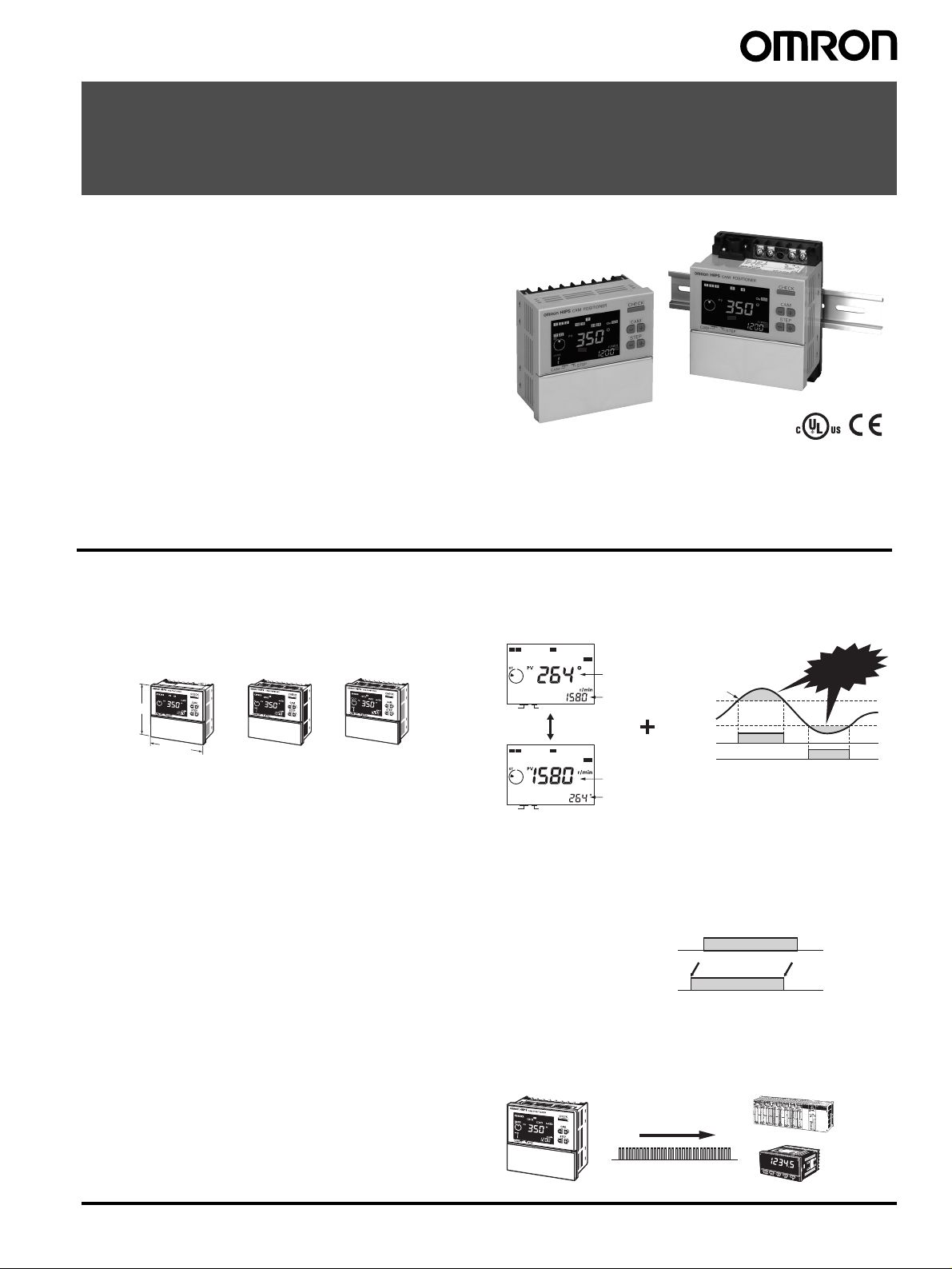
Cam Positioner
H8PS
Please read and understand this catalog before purchasing the
products. Please consult your OMRON representative if you have any
questions or comments. Refer to Warranty and Application
Considerations (page 32), and Safety Precautions (pages 17 and 18).
This Compact Cam Positioner, Popular for
It’s Ease-of-use, Now Comes with Even
Better Functions.
• Compact 8-, 16-, and 32-output Models available that are 1/4DIN size at 96 x 96 mm.
• High-speed operation at 1,600 r/min and high-precision settings
to 0.5° ensure widespread application.
• Highly visible display with backlit negative transmissive LCD.
• Advance angle compensation function to compensate for output
delays.
• Bank function for multi-product production (8 banks).
(H8PS-16@/-32@ models.)
Features
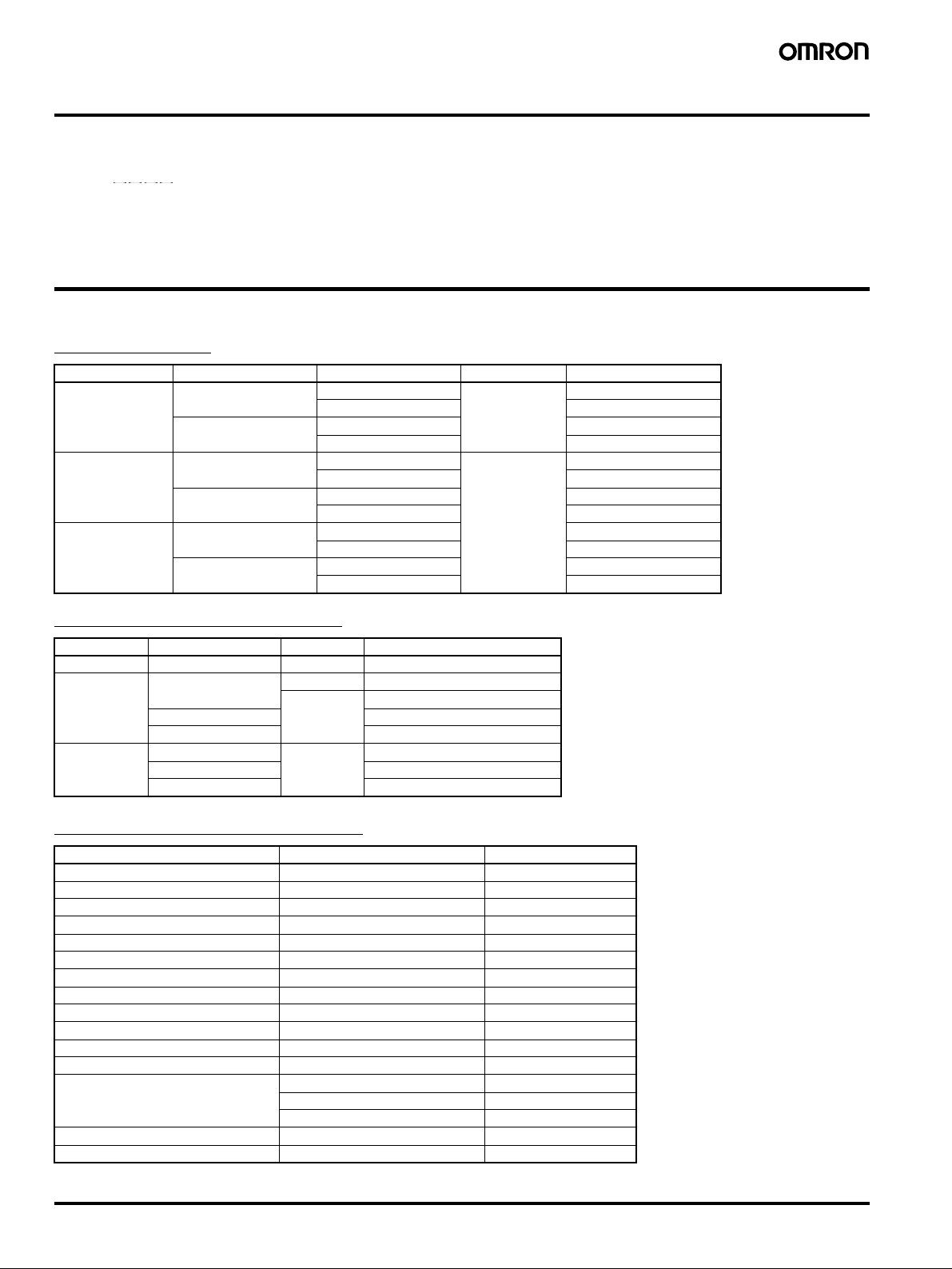
Models with 8, 16, or 32 Outputs
The lineup includes Models with 32 outputs in a compact 1/4-DIN
size. Using the optional Parallel Input Adapter (Y92C-30) enables
expanding to up to 64 outputs for one encoder to support anything
from a simple positioning application to a large-scale system.
8-output Models 16-output Models 32-output Models
96 mm
96 mm
Simple Programming
The programming method is designed based on a one key-one
action concept for settings that could not be simpler. Both initial
settings and factory adjustments are effort-free.
Large, Backlit Negative LCDs
Large LCDs, red for the process value and green for set values, show
a wealth of operation information, making operating status visible at
a glance.
High Speed Up To 1,600 r/min
High Precision Up To 0.5
High-speed, high-precision applications can be easily handled and
productivity increased.
° (at 720 Resolution)
Bank Function for Multi-product Production
Up to eight different programs can be registered in advance to
enable fast and easy switching between products (16/32-output
Models only).
USB Communications for Easy Setting from
a Computer
Optional Support Software can be used to enable programming from
a personal computer via USB communications. Programs can be
easily copied, saved, printed, and much more.
Speed Display and Speed Alarm Output
Both the speed (rotations/minutes) and present angular position can
be displayed at the same time. Alarm outputs can be produced for
both upper and lower speed limits.
12 7
CAM
12 7
CAM
STEP
STEP
RUN
Switchable
RUN
Present angular
position
Speed
Speed
Present angular
position
Upper limit
Lower limit
Upper limit
alarm output
Lower limit
alarm output
Speed
Errors
Advance Angle Compensation Function to
Compensate for Output Delays
The advance angle compensation (ADV) function automatically
advances the ON/OFF angle of outputs in proportion to machine
(encoder) speed to compensate for the delay in timing of ON/OFF
operation. ADV values can be set individually for 7 cam outputs.
Cam program settings
At high-speed (400 r/min)
100°
8° compensation
92° 172°
180°
Pulse Output for Timing Control
The number of pulses per rotation and the pulse output start angle
can be set to enable operations like adjusting timing with a PLC or
outputting to a rotation meter.
Pulse output
PLC
Rotation meter
Cam Positioner H8PS 1
Model Number Structure
■ Model Number Legend
H8PS-@@@@
1. Number of outputs
1 2 3 4
8: 8 outputs
16: 16 outputs
32: 32 outputs
2. Panel language
B: English
3. Mounting method
None: Flush mounting
F: Surface mounting/
track mounting
Ordering Information
■ List of Models
Cam Positioner
Number of outputs Mounting method Output configuration Bank function Model
8 outputs Flush mounting NPN transistor output No H8PS-8B
PNP transistor output H8PS-8BP
Surface mounting/
track mounting
16 outputs Flush mounting NPN transistor output Yes H8PS-16B
Surface mounting/
track mounting
32 outputs Flush mounting NPN transistor output H8PS-32B
Surface mounting/
track mounting
Dedicated Absolute Encoder
NPN transistor output H8PS-8BF
PNP transistor output H8PS-8BFP
PNP transistor output H8PS-16BP
NPN transistor output H8PS-16BF
PNP transistor output H8PS-16BFP
PNP transistor output H8PS-32BP
NPN transistor output H8PS-32BF
PNP transistor output H8PS-32BFP
4. Output configuration
None: NPN transistor output
P: PNP transistor output
Type Resolution Cable length Model
Economy 256 2 m E6CP-AG5C-C 256 2M
Standard 256 1 m E6C3-AG5C-C 256 1M
2 m E6C3-AG5C-C 256 2M
360 E6C3-AG5C-C 360 2M
720 E6C3-AG5C-C 720 2M
Rigid 256 2 m E6F-AG5C-C 256 2M
360 E6F-AG5C-C 360 2M
720 E6F-AG5C-C 720 2M
Accessories (Order Separately)
Name Specification Model
Discrete Wire Output Cable 2 m Y92S-41-200
Connector-type Output Cable 2 m E5ZE-CBL200
Support Software CD-ROM H8PS-SOFT-V1
USB Cable A miniB, 2 m Y92S-40
Shaft Coupling for the E6CP Axis: 6 mm dia. E69-C06B
Shaft Coupling for the E6C3 Axis: 8 mm dia. E69-C08B
Shaft Coupling for the E6F Axis: 10 mm dia. E69-C10B
Extension Cable (See note.) 5 m (same for E6CP, E6C3, and E6F) E69-DF5
Parallel Input Adapter Two Units can operate in parallel. Y92C-30
Protective Cover --- Y92A-96B
Watertight Cover --- Y92A-96N
Track Mounting Base --- Y92F-91
Mounting Track 50 cm
End Plate --- PFP-M
Spacer --- PFP-S
Note: Ask your OMRON representative about the availability of non-standard lengths.
× 7.3 mm (l × t) PFP-50N
1 m
× 7.3 mm (l × t) PFP-100N
× 16 mm (l × t) PFP-100N2
1 m
2 Cam Positioner H8PS
Specifications
■ Ratings
Item H8PS-@BH8PS-@BF H8PS-@BP H8PS-@BFP
Rated supply voltage 24 VDC
Operating voltage range 85% to 110% of rated supply voltage
Mounting method Flush mounting Surface mounting,
Power consumption Approx. 4.5 W at 26.4 VDC for 8-output models
Inputs Encoder input Connections to a dedicated absolute encoder
External
inputs
Outputs Cam outputs
RUN output
Pulse output NPN open-collector transistor output
Number of outputs 8-output Models: 8 cam outputs, 1 RUN output, 1 pulse output
Number of banks 8 banks (for 16-/32-output Models only)
Display method 7-segment, negative transmissive LCD (Main Display: 11 mm (red), Sub-display: 5.5 mm (green))
Memory backup method EEPROM (overwrites: 100000 times min.) that can store data for 10 years min.
Ambient operating
temperature
Storage temperature
Ambient humidity 25% to 85%
Degree of protection Panel surface: IP40, Rear case: IP20
Case color Light gray (Munsell 5Y7/1)
Input
signals
Input type No voltage inputs: ON impedance:1 k
Approx. 6.0 W at 26.4 VDC for 16-/32-output models
8-output Models: None
16-/32-output Models: Bank inputs 1/2/4, origin input, start input
NPN open-collector transistor outputs
30 VDC max.,
100 mA max. (Do not exceed 1.6 A total for all cam
outputs and the RUN output.),
residual voltage: 2 VDC max.
30 VDC max.,
30 mA max.,
residual voltage: 0.5 VDC max.
16-output Models: 16 cam outputs, 1 RUN output, 1 pulse output
32-output Models: 32 cam outputs, 1 RUN output, 1 pulse output
−10 to 55°C (with no icing or condensation)
−25 to 65°C (with no icing or condensation)
track mounting
Ω max. (Leakage current: approx. 2 mA at 0 Ω)
ON residual voltage: 2 V max., OFF impedance: 100 k
Minimum input signal width: 20 ms
Flush mounting Surface mounting,
track mounting
Ω min., Applied voltage: 30 VDC max.
PNP open-collector transistor outputs
30 VDC max. (26.4 VDC for 16-/32-output Models),
100 mA max. (Do not exceed 1.6 A total for all cam
outputs and the RUN output.),
residual voltage: 2 VDC max.
PNP open-collector transistor output
30 VDC max. (26.4 VDC for 16-/32-output Models)
30 mA max.,
residual voltage: 2 VDC max.
Cam Positioner H8PS 3

■ Characteristics
Setting unit 0.5
Number of steps Up to 10 steps can be set for each cam to turn the output ON/OFF 10 times. (See note 2.)
Inputs Encoder input Connections to a dedicated absolute encoder
Encoder cable extension
distance
Output response time 0.3 ms max.
Insulation resistance 100 M
Dielectric strength 1000 VAC, 50/60 Hz for 1 min between current-carrying terminals and exposed non-current-carrying metal
Impulse withstand voltage 1 kV between power terminals
Noise immunity
Static immunity 8 kV (malfunction), 15 kV (destruction)
Vibration
resistance
Shock
resistance
Approved safety standards cULus (Listing): UL508/CSA C22.2 No. 14
EMC (EMI) EN61326
Weight Approx. 300 g (Cam Positioner main unit only)
Note: 1. Cam output precision, however, is 2° max. for Encoder with 256 resolution (P/R).
Destruction 10 to 55 Hz with 0.75-mm single amplitude each in 3 directions for 2 hours each
Malfunction 10 to 55 Hz with 0.5-mm single amplitude each in 3 directions for 10 minutes each
Destruction
Malfunction
2. Although 32-output Models can have 10 steps set for any one output, there must be no more than 160 steps total set for all cam outputs.
3. The maximum is 1000 r/min when an E6CP-AG5C-C Encoder is connected.
4. ADV stands for Advance Angle Compensation.
° increments at a resolution of 720, 1° increments at a resolution of 256 or 360 (See note 1.)
• Response rotation speed (in Run/Test Mode)
1600 r/min max. at a resolution of 256 or 360 (1200 r/min max. if ADV function is set for 4 or more cams)
(See notes 3 and 4.)
800 r/min max. at a resolution of 720 (600 r/min max. if ADV function is set for 4 or more cams)
• Includes error data detection
256/360 resolution
100 m max. at 330 r/min or less
52 m max. at 331 to 1200 r/min (331 to 900 r/min if ADV function is set for 4 or more cams)
12 m max. at 1201 to 1600 r/min (901 to 1200 r/min if ADV function is set for 4 or more cams)
720 resolution
100 m max. at 330 r/min or less
52 m max. at 331 to 600 r/min (331 to 450 r/min if ADV function is set for 4 or more cams)
12 m max. at 601 to 800 r/min (451 to 600 r/min if ADV function is set for 4 or more cams)
Ω min. (at 500 VDC) between current-carrying terminals and exposed non-current-carrying metal
parts, between all current-carrying parts and the USB connector
parts
500 VAC, 50/60 Hz for 1 min between current-carrying section and USB connector, and between currentcarrying terminals and non-current-carrying metal part of output connector
1.5 kV between current-carrying terminals and exposed non-current-carrying metal parts
±480 V between power terminals, ±600 V between input terminals
Square-wave noise by noise simulator (pulse width: 100 ns/1
2
300 m/s
200 m/s
Emission Enclosure: EN55011 Group1 Class A
(EMS) EN61326
Immunity ESD: EN61000-4-2: 4 kV contact discharge
Immunity RF-interference: EN61000-4-3: 10 V/m (Amplitude-modulated, 80 MHz to 1 GHz)
Immunity Conducted Disturbance EN61000-4-6: 10 V (0.15 to 80 MHz)
Immunity Burst: EN61000-4-4: 2 kV for power-line
Immunity Surge: EN61000-4-5: 1 kV line to line (power line)
3 times each in 6 directions
2
3 times each in 6 directions
8 kV air discharge
10 V/m (Pulse-modulated, 900 MHz
1 kV for I/O signal-line
2 kV line to ground (power line)
µs, 1-ns rise)
±5 MHz)
4 Cam Positioner H8PS

■ Functions
Item H8PS-8@ H8PS-16@ H8PS-32@
Encoder rotation direction
switching
Encoder origin designation The present display angular
Angle display switch Converts the Absolute Encoder value display from 256 divisions/revolution to 360
Rotation display monitor Graphically displays the Encoder rotational angular position.
Teaching function Sets the cam output ON/OFF angle based on actual machine (Encoder) operation.
Pulse output Outputs a preset number of pulses per Encoder rotation. It also sets the pulse output start angle.
Switching the angle and
speed displays
Bank function --- Enables the entire cam program to be changed at one time by switching
Advance angle compensation
(ADV) function
Speed alarm output A specified cam output can be used as an Encoder speed alarm output.
All protection function Disables all key and switch operations in Run Mode to prevent incorrect or unauthorized operation.
Cam protection function Prohibits program changes at the cam output level. Any cam numbers can be protected.
Step number limit Limits the number of steps that can be set per cam output. Prohibits incorrect operations by adding to the
Output prohibit --- The start input can be turned OFF in Run or Test Mode to prohibit cam
Support Software settings --- Programs can be uploaded or downloaded easily by connecting a personal
Encoder data can be set with a DIP switch to forward (CW) or reverse (CCW) direction.
position can be set to 0
pressing the ORIGIN Key on the
front panel.
Displays both the present angular position and the number of Encoder revolutions (speed) in Run Mode.
Switches back and forth between the main display showing the present angular position with the sub-display
showing the speed and the main display showing the speed with the sub-display showing the present angular
position.
Automatically advances the ON/OFF angle of cam outputs in proportion to machine (encoder) speed to
compensate for the delay in timing of ON/OFF operation. ADV values can be set individually for 7 cam outputs.
The function can output upper and lower limit speed alarms.
program.
° (origin) by
The present display angular position can be set to 0
origin input terminal or the ORIGIN Key on the front panel.
Note: All banks use the same origin.
banks (0 to 7).
The bank that is running can be switched using the bank input terminal or the
BANK Key on the front panel.
Also enables programs to be copied between banks.
output.
Note: Use this function carefully for the application because no cam outputs
are provided when the start input is turned OFF.
computer to the Cam Positioner using a USB Cable (Y92S-40, sold
separately) and the Support Software (H8PS-SOFT-V1, sold separately).
° (origin) by using the
°/revolution.
Cam Positioner H8PS 5
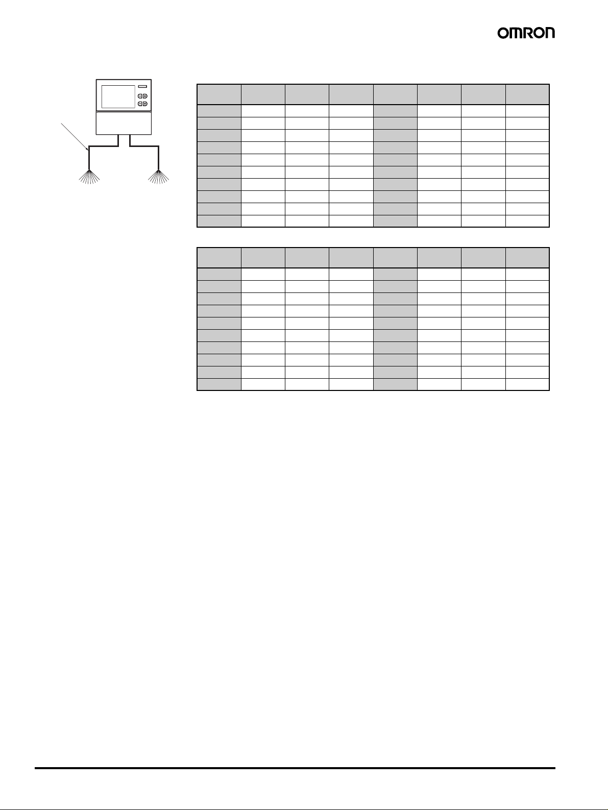
Connections
C
■ Terminal Arrangement
H8PS-8@ (8-output Models) H8PS-16@/-32@ (16-/32-output Models)
NPN Output,
Flush Mounting
H8PS-8@
Alignment markings
Encoder
RUN output
Pulse output
9 10111213
24 VD
+ −
Not used
NPN Output,
Flush Mounting
H8PS-16@/-32@
(Rear view)
Origin
Bank 4
COM
Bank 1
Bank 2
Start
Not used
678910111213
Not used
NPN Output,
Surface Mounting
H8PS-8@F
Alignment markings
PNP Output,
Flush Mounting
H8PS-8@P
Alignment markings
(Rear view)
(Front view)
12345678
am 1
am 2
am 3
am 4
am 5
am 6
am 7
am 8
Encoder
24 VDC
+ −
RUN output
Not used
Pulse output
910111213
12345678
am 1
am 2
am 3
am 4
am 5
am 6
am 7
Encoder
24 VDC
+ −
Vs (See note.)
RUN output
Pulse output
9 10111213
am 8
NPN Output,
Surface Mounting
H8PS-16@F/-32@F
(Front view)
PNP Output,
Flush Mounting
H8PS-16@P/-32@P
(Rear view)
12345
+ −
Not used
24 VDC
COM
678910111213
12345
+ −
24 VDC
COM
6 7 8 9 10111213
Bank 1
Bank 1
Bank 2
Pulse output
Encoder
Bank 4
Bank 2
Not used
Pulse output
Encoder
Origin
Bank 4
RUN output
Origin
Start
RUN output
Start
Not used
Not used
Not used
Not used
Alignment markings
Alignment markings
(Rear view)
Note: The VS terminal
is not internally
connected to the
12345678
positive (+) power
supply terminal.
PNP Output,
Cam 1
Cam 2
Cam 3
Encoder
Cam 4
Surface Mounting
H8PS-8@FP
Alignment markings
Note: The VS terminal
(Front view)
Pulse output
9 10111213
is not internally
connected to the
positive (+) power
supply terminal.
12345678
Cam 1
Cam 2
Cam 3
Cam 4
6 Cam Positioner H8PS
Cam 5
Cam 6
24 VDC
+ −
Vs (See note.)
RUN output
Cam 5
Cam 6
Cam 7
Cam 7
Cam 8
Cam 8
Note: The VS terminal
is not internally
connected to
the positive (+)
power supply
terminal.
PNP Output,
Surface Mounting
H8PS-16@FP/-32@FP
(Front view)
Note: The VS terminal
is not internally
connected to the
positive (+) power
supply terminal.
12345
+ −
24 VDC
24 VDC
RUN output
Pulse output
Vs (See note.)
Encoder
Origin
Bank 4
COM
Bank 1
Bank 2
6 7 8 9 10111213
12345
+ −
Pulse output
Vs (See note.)
Encoder
RUN output
Start
Not used
Alignment markings
Not used
Alignment markings

Output Cable Connections (16-/32-output Models Only)
Flush Mounting Models Surface Mounting Models
Output Connector 1 (CN1)
Output Connector 2 (CN2) (See note.)
(Bottom view) (Bottom view)
Output Connector Output signals
Output Connector 1 (CN1) Cam 1 to Cam 16, COM, Vs
Output Connector 2 (CN2) (See note.) Cam 17 to Cam 32, COM, Vs
Note: The 16-output Models do not have CN2 Connectors.
1. E5ZE-CBL200 Connector-type Output Cable (Order Separately) Connections
H8PS-16@/-32@
E5ZE-CBL200
Connector-type
Output Cable
(Order Separately)
Output
Cable 1
(CN1)
XG4M-2030
MIL Connector
(made by OMRON)
Output Cable 1 Wiring Table Output Cable 2 Wiring Table
Outputs Connector
pin No.
Cam 1 20 Cam 9 19
Cam 2 18 Cam 10 17
Cam 3 16 Cam 11 15
Cam 4 14 Cam 12 13
Cam 5 12 Cam 13 11
Cam 6 10 Cam 14 9
Cam 7 8 Cam 15 7
Cam 8 6 Cam 16 5
COM 4 COM 3
Vs 2 Vs 1
(CN2)
Output
Cable 2
Outputs Connector
pin No.
Output Connector 1 (CN1)
Output Connector 2 (CN2) (See note.)
Pin Arrangement of XG4M-2030 Connectors
1 3 5 7 9 1113151719
2 4 6 8 10 12 14 16 18 20
Outputs Connector
pin No.
Cam 17 20 Cam 25 19
Cam 18 18 Cam 26 17
Cam 19 16 Cam 27 15
Cam 20 14 Cam 28 13
Cam 21 12 Cam 29 11
Cam 22 10 Cam 30 9
Cam 23 8 Cam 31 7
Cam 24 6 Cam 32 5
COM 4 COM 3
Vs 2 Vs 1
Outputs Connector
pin No.
Using Connector-Terminal Block Conversion Units
H8PS-16@/-32@
E5ZE-CBL200
Connector-type
Output Cable
(Order Separately)
(CN1)
XW2D-20G6
Connector-Terminal Block
Conversion Unit (Order Separately)
(CN2)
Output Cable 2Output Cable 1
Terminal Arrangement of the XW2D-20G6 Connector-Terminal Block Conversion Unit
Output Cable 1
COM
Vs
A1 A2 A3 A4 A5 A6 A7 A8 A9 A10
B1 B2 B3 B4 B5 B6 B7 B8 B9 B10
Vs
COM
Cam 16
Cam 8
Cam 15
Cam 7
Cam 14
Cam 6
Cam 13
Cam 5
Cam 12
Cam 4
Cam 11
Cam 3
Cam 10
Cam 2
Cam 9
Cam 1
Output Cable 2
Vs
COM
Cam 32
Cam 31
Cam 30
Cam 29
Cam 28
A1 A2 A3 A4 A5 A6 A7 A8 A9 A10
B1 B2 B3 B4 B5 B6 B7 B8 B9 B10
Vs
COM
Cam 24
Cam 23
Cam 22
Cam 21
Cam 20
Cam 27
Cam 19
Cam 26
Cam 18
Cam 25
Cam 17
Cam Positioner H8PS 7
2. Y92S-41-200 Discrete Wire Output Cable (Order Separately) Connections
Y92S-41-200
Discrete Wire
Output Cable
(Order Separately)
H8PS-16@/-32@
(CN1)
(CN2)
Output Cable 2 Output Cable 1
Output Cable 1 Wiring Table
Outputs Cable
color
Marks Marking
color
Outputs Cable
color
Cam 1 Orange ■ Black Cam 9 Orange ■ Red
Cam 2 Gray ■ Black Cam 10 Gray ■ Red
Cam 3 White ■ Black Cam 11 White ■ Red
Cam 4 Yellow ■ Black Cam 12 Ye l l o w ■ Red
Cam 5 Pink ■ Black Cam 13 Pink ■ Red
Cam 6 Orange ■ ■ Black Cam 14 Orange ■ ■ Red
Cam 7 Gray ■ ■ Black Cam 15 Gray ■ ■ Red
Cam 8 White ■ ■ Black Cam 16 White ■ ■ Red
COM Yellow ■ ■ Black COM Ye l l o w ■ ■ Red
Vs Pink ■ ■ Black Vs Pink ■ ■ Red
Output Cable 2 Wiring Table
Outputs Cable
color
Marks Marking
color
Outputs Cable
color
Cam 17 Orange ■ Black Cam 25 Orange ■ Red
Cam 18 Gray ■ Black Cam 26 Gray ■ Red
Cam 19 White ■ Black Cam 27 White ■ Red
Cam 20 Yellow ■ Black Cam 28 Ye l l o w ■ Red
Cam 21 Pink ■ Black Cam 29 Pink ■ Red
Cam 22 Orange ■ ■ Black Cam 30 Orange ■ ■ Red
Cam 23 Gray ■ ■ Black Cam 31 Gray ■ ■ Red
Cam 24 White ■ ■ Black Cam 32 White ■ ■ Red
COM Yellow ■ ■ Black COM Ye l l o w ■ ■ Red
Vs Pink ■ ■ Black Vs Pink ■ ■ Red
Marks Marking
color
Marks Marking
color
8 Cam Positioner H8PS
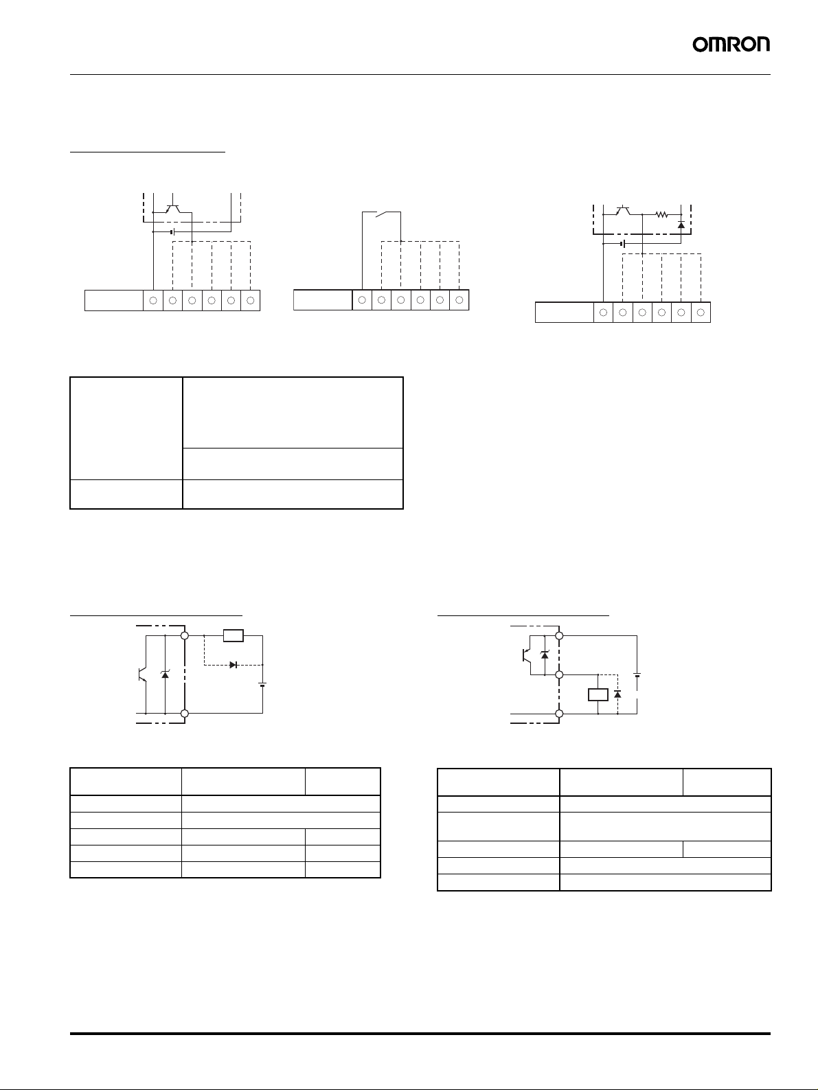
■ Input Connections
p
Only the Encoder inputs are connected with 8-output Models. The inputs are no-voltage (short-circuit or open) inputs.
No-voltage Inputs
Open Collector
PLC,
sensor,
etc.
Contact Input
Voltage-output sensors can also be connected.
Connection Examples
Sensor, etc.
COM
H8PS-16@
H8PS-32@
Note: O
6 7 8 9
erates when the transistor turns ON.
Bank 1
Bank 2
Bank 4
10 11
Origin
Start
H8PS-16@
H8PS-32@
Note: Operates when the contact turns ON.
COM
Bank 1
6 7 8 9
No-voltage Input Signal Levels
No-contact inputs Short-circuit level for transistor ON
• Residual voltage: 2 V max.
• Impedance when ON: 1 k
Ω max.
(The leakage current is approx. 2 mA
when the impedance is 0
Ω.)
Open level for transistor OFF
• Impedance when OFF: 100 k
Ω min.
Contact inputs Use a contact that can adequately switch
2 mA at 5 V.
Note: Use a maximum DC power supply of 30 V.
■ Output Connections
Note: Internal circuit damage may result from a short circuit in the load.
NPN Output Models
Outputs
Load
Bank 2
Bank 4
Origin
Start
10 11
H8PS-16@
H8PS-32@
Note: Operates when the transistor turns ON.
PNP Output Models
Vs
COM
Bank 1
Bank 2
6 7 8 9
Bank 4
10 11
Origin
Start
(See note.)
COM/(−)
Note: Always connect a diode to absorb
counter-electromotive force when
connecting an inductive load.
Item Cam outputs,
RUN output
Pulse output
Output method NPN open collector
Dielectric strength 30 VDC
Rated current 100 mA (See note.) 30 mA
Residual voltage 2 VDC max. 0.5 VDC max.
Leakage current 100
µA max. 5 µA max.
Note: Do not exceed 1.6 A total for all cam outputs and the RUN
output.
Note: Always connect a diode to absorb
counter-electromotive force when
connecting an inductive load.
Item Cam outputs,
Output method PNP open collector
Dielectric strength 8-output Models: 30 VDC
Rated current 100 mA (See note.) 30 mA
Residual voltage 2 VDC max.
Leakage current 100
Note: Do not exceed 1.6 A total for all cam outputs and the RUN
Outputs
(See note.)
Load
COM/(−)
RUN output
Pulse output
16-/32-output Models: 26.4 VDC
µA max.
output.
Cam Positioner H8PS 9
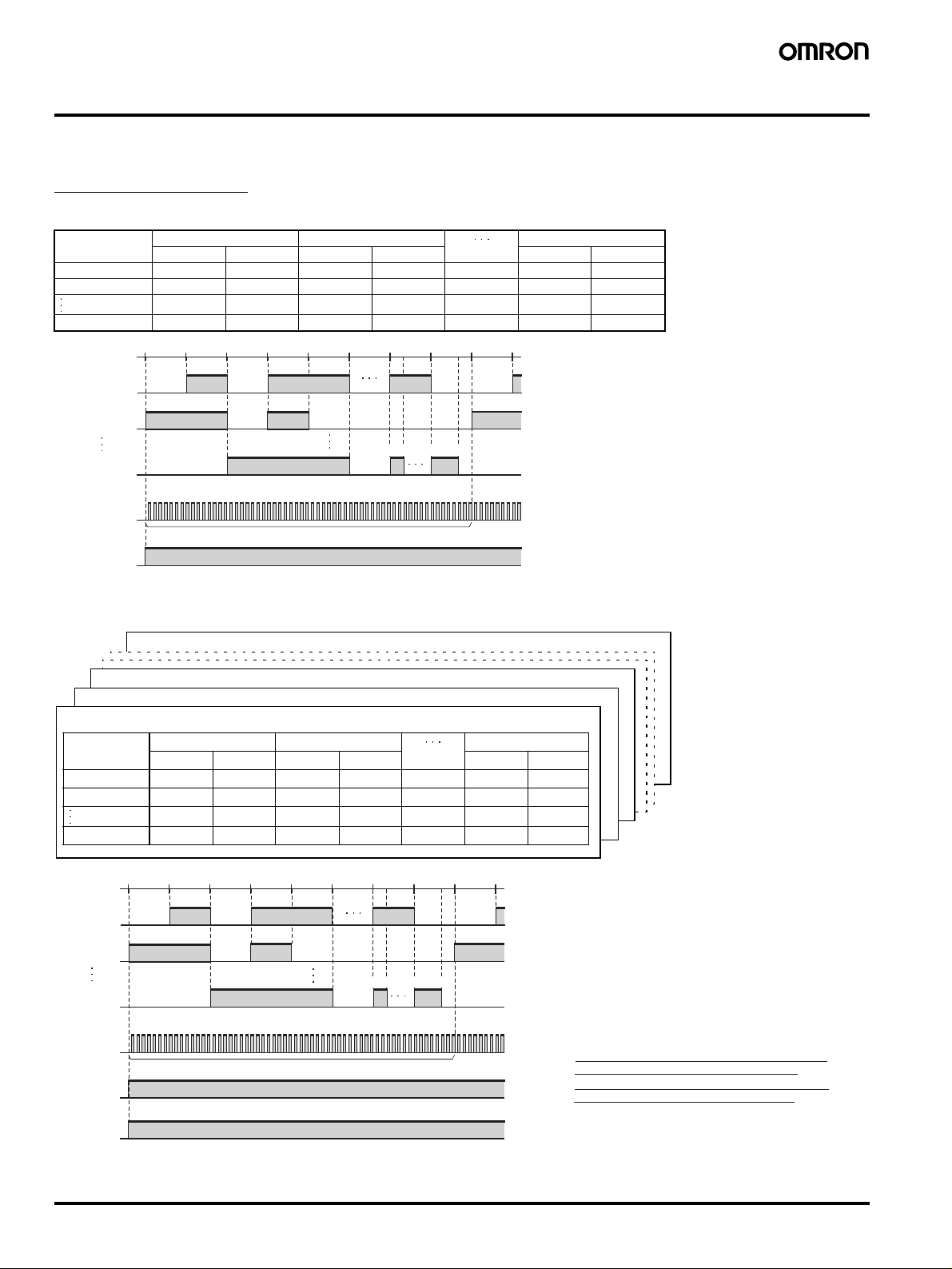
Operating Mode
■ Functions
The H8PS Cam Positioner receives angle signal inputs from the Dedicated Absolute Encoder and outputs the preset ON/OFF angles as cam outputs.
Program Examples
1. H8PS-8@ (8-output Models)
Cam output
(cam number)
145° 90° 135° 225° 270° 315°
20° 90° 135° 180° --- ---
890° 225° 270° 285° 315° 345°
0° 45° 90° 135° 180° 225° 270° 315° 0° 45°
Step 0 Step 1 Step 9
ON angle OFF angle ON angle OFF angle ON angle OFF angle
Cam output 1
Cam output 2
Cam output 8
Pulse output
(See note 1.)
RUN output
Step 0
Step 0
Outputs a preset number of pulses per Encoder rotation. (Default setting: 60 pulses/revolution)
ON during Run or Test Mode. OFF when an error occurs.
Step 1
Step 1
Step 0
(ON/OFF ratio 1:1)
Step 9
Step 1 Step 9
2. H8PS-16@ /-32@ (16-/32-output Models)
Cam Program (Bank No. 7)
Cam Program (Bank No. 2)
Cam Program (Bank No. 1)
Cam Program (Bank No. 0)
Cam output
(cam number)
145° 90° 135° 225° 270° 315°
20° 90° 135° 180° --- ---
32 90° 225° 270° 285° 315° 345°
Step 0 Step 1 Step 9
ON angle OFF angle ON angle OFF angle ON angle OFF angle
Note 1: The number of pulses per Encoder rotation
and the pulse output start angle can be set.
Note 2: With counterclockwise rotation (359°, 358°
...1°, 0°), step 0 for cam output 1 turns ON
at 89° and OFF at 44° at in the diagram.
0° 45° 90° 135° 180° 225° 270° 315° 0° 45°
Cam output 1
Cam output 2
Cam output 32
Pulse output
(See note 1.)
Step 0
Outputs a preset number of pulses per Encoder rotation. (Default setting: 60 pulses/revolution)
Step 1
Step 1
Step 0
(ON/OFF ratio 1:1)
Step 9Step 0
Step 1
Step 9
Note 1: The number of pulses per Encoder rotation
and the pulse output start angle can be set.
Note 2: Be sure to turn ON the start input in Run and
Test modes. Otherwise, there will be no
outputs (output prohibited), including the cam
RUN output
Start input
(See note 2.)
ON during Run or Test Mode. OFF when an error occurs.
Note 3: With counterclockwise rotation (359°, 358°
outputs, pulse output, and RUN output.
...1°, 0°), step 0 for cam output 1 turns ON at
89° and OFF at 44° in the diagram.
Note: The entire cam program can be changed at one time with 16- and 32-output Models with the bank function (banks 0 to 7).
For details on the procedure for switching banks, refer to page 28.
10 Cam Positioner H8PS
 Loading...