

Page 1
Preset Counter/Timer H8GN C-59
Counters
Preset Counter/Timer
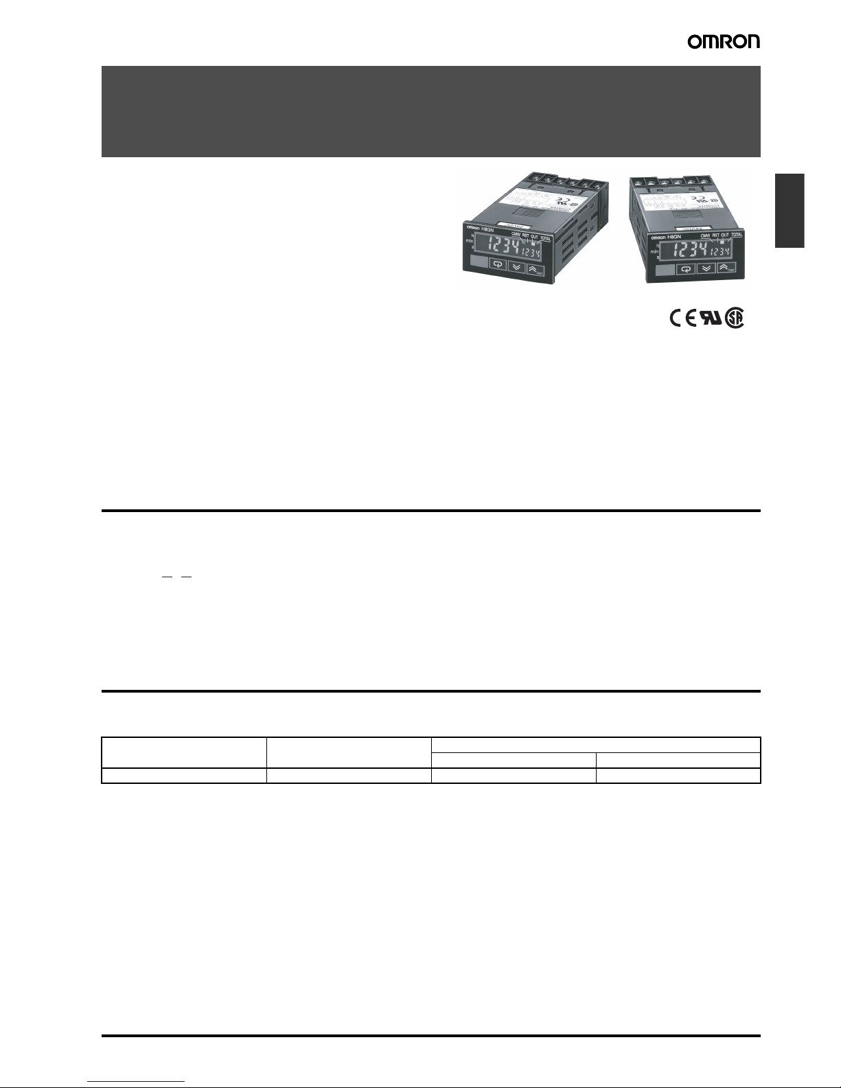
H8GN
World’s Smallest Compact Preset Counter/
Timer
1/32-mm DIN with Communications
• Only 48 x 24 x 83 mm (W x H x D)
• Switch between 4-digit preset counter and 4-digit timer operation.
• While using the preset counter, it is possible to switch the display to monitor the totalizing count value (8 digits).
• Built-in prescaling for counter operation.
• ON/OFF-duty adjustable flicker mode that can be used to perform cyclic control is available for timer operation.
• Four preset values that can be changed by the front panel key
(SV-bank).
• Finger protection terminal block to meet VDE0106/P100.
• Panel surface compatible with NEMA4X/IP66.
• Conforms to UL, CSA, and IEC safety standards as well as CE
Marking.
• Six-language instruction manual provided.
Model Number Structure
■ Model Number Legend
1. Supply Voltage
D: 24 VDC
2. Communications Output Type
None: Communications not supported
FLK: RS-485
Ordering Information
■ List of Models
H8GN-AD-@
1 2
Supply voltage Output Communications
No communications RS-485
24 VDC Contact output (SPDT) H8GN-AD H8GN-AD-FLK
Page 2
C-60 Preset Counter/Timer H8GN
Specifications
■ Ratings
Note: The figures given for maximum counting speed are for incrementing or decrementing operation with a prescale value of ×1. If prescaling is
used and 5 kHz is set, the maximum counting speed will be reduced to about half. The maximum counting speed will also be reduced to
about half when the up/down mode is selected.
Rated supply voltage 24 VDC
Operating voltage range 85% to 110% of rated supply voltage
Power consumption 1.5 W max. (for max. DC load) (Inrush current: 15 A max.)
Mounting method Flush mounting
External connections Screw terminals (M3 screws)
Terminal screw tightening torque 0.5 N⋅m max.
Attachment Waterproof packing, flush mounting bracket
Display 7-segment, negative transmissive LCD; time display (h, min, s); CMW, OUT, RST, TOTAL
Present value (red, 7-mm-high characters); Set value (green, 3.4-mm-high characters)
Digits PV: 4 digits
SV: 4 digits
When total count value is displayed: 8 digits
(Zeros suppressed)
Memory backup EEPROM (non-volatile memory) (number of writes: 100,000 times)
Counter Maximum counting speed 30 Hz or 5 kHz (See note.)
Counting range −999 to 9,999
Input modes Increment, decrement, individual, quadrature inputs
Output modes N, F, C, or K
Timer Time ranges 0.000 to 9.999 s, 0.00 to 99.99 s, 0.0 to 999.9 s, 0 to 9999 s, 0 min 00 s to 99 min 59 s, 0.0 to
999.9 min, 0 h 00 min to 99 h 59 min, 0.0 h to 999.9 h, 0 h to 9999 h
Timer modes Elapsed time (Up), remaining time (Down)
Output modes A, B, D, E, F, or Z
Inputs Input signals For Counter: CP1, CP2, and reset
For Timer: Start, gate, and reset
Input method No-voltage input (contact short-circuit and open input)
Short-circuit (ON) impedance: 1 KΩ max. (Approx. 2 mA runoff current at 0 Ω)
Short-circuit (ON) residual voltage:2 VDC max.
Open (OFF) impedance: 100 kΩ min.
Applied voltage: 30 VDC max.
Start, reset, gate Minimum input signal width: 1 or 20 ms (selectable)
Power reset Minimum power-opening time: 0.5 s
Control output SPDT contact output: 3 A at 250 VAC/30 VDC, resistive load (cos φ = 1)
Minimum applied load 10 mA at 5 VDC (failure level: P, reference value)
Reset system External, manual, and power supply resets (for timer in A, B, D, E, or Z modes)
Sensor waiting time 260 ms max. (Inputs cannot be received during sensor wait time if control outputs are turned OFF.)
Page 3
Preset Counter/Timer H8GN C-61
Counters
■ Characteristics
Note: Refer to the Life-test Curve.
Timer function Accuracy of operating
time and setting error
(including temperature
and voltage effects)
Signal start: ± 0.03% ± 30 ms max.
Power-ON start: ± 0.03% ± 50 ms max.
Insulation resistance 100 MΩ min. (at 500 VDC)
Dielectric strength 1,500 VAC, 50/60 Hz for 1 min between output terminals and non-current-carrying metal
parts
510 VAC, 50/60 Hz for 1 min between current-carrying terminals (except output terminals)
and non-current-carrying metal parts
1,500 VAC, 50/60 Hz for 1 min between output terminals and current-carrying terminals (except output terminals)
500 VAC, 50/60 Hz for 1 min between communications terminals and current-carrying terminals (except output terminals)
1,000 VAC, 50/60 Hz for 1 min between contacts not located next to each other
Noise immunity Square-wave noise by noise simulator;
±480 V (between power terminals), ± 600 V (between input terminals)
Static immunity ± 8 kV (malfunction), ± 15 kV (destruction)
Vibration resistance Malfunction 10 to 55 Hz with 0.35-mm single amplitude each in three directions for 10 min
Destruction 10 to 55 Hz with 0.75-mm single amplitude each in three directions for 2 h
Shock resistance Malfunction
100 m/s
2
, 3 times each in six directions
Destruction
300 m/s
2
, 3 times each in six directions
Life expectancy Mechanical 10 million operations
Electrical 100,000 operations min. (3 A at 250 VAC, resistive load) (See note.)
Ambient temperature Operating −10°C to 55°C (with no icing or condensation)
Storage −25°C to 65°C (with no icing or condensation)
Ambient humidity 25% to 85%
EMC (EMI): EN61326
Emission Enclosure: EN55011 Group 1 Class A
(EMS): EN61326
Immunity ESD: EN61000-4-2: 4 kV contact discharge (level 2)
8 kV air discharge (level 3)
Immunity RF-interference: EN61000-4-3: 10 V/m (Amplitude-modulated,
80 MHz to 1 GHz) (level 3);
10 V/m (Pulse-modulated,
900 MHz ± 5 MHz) (level 3)
Immunity Conducted
Disturbance: EN61000-4-6: 3 V (0.15 to 80 MHz) (level 2)
Immunity Burst: EN61000-4-4: 2 kV power-line (level 3);
1 kV I/O signal-line (level 4);
1 kV communications-line (level 3)
Immunity Surge: EN61000-4-5: 1 kV between lines
(power and output lines) (level 3);
2 kV between grounds
(power and output lines) (level 3)
Approved standards UL508, CSA C22.2 No.14
Conforms to EN61010-1/IEC61010-1 (Pollution degree 2/overvoltage category II)
Conforms to VDE0106/P 100 (Finger Protection)
Case color Rear section: Gray smoke; Front section: N1.5 (black)
Degree of protection Panel surface: IP66 and NEMA Type 4X (indoors)
Rear case: IP20
Terminal block: IP20
Weight Approx. 80 g
Page 4
C-62 Preset Counter/Timer H8GN
■ Communications Specifications
Note: The baud rate, data bit length, stop bit length, and vertical parity can be individually set using the communications setting level.
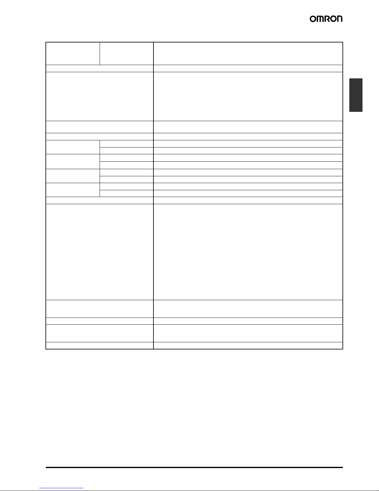
■ Life-test Curve (Reference Values)
Resistive Load
Reference: A maximum current of 0.15 A can be switched at
125 VDC (cosφ = 1) and a maximum current of 0.1 A can
be switched if L/R is 7 ms. In both cases, a life of
100,000 operations can be expected. The minimum
applicable load is 10 mA at 5 VDC (failure level: P).
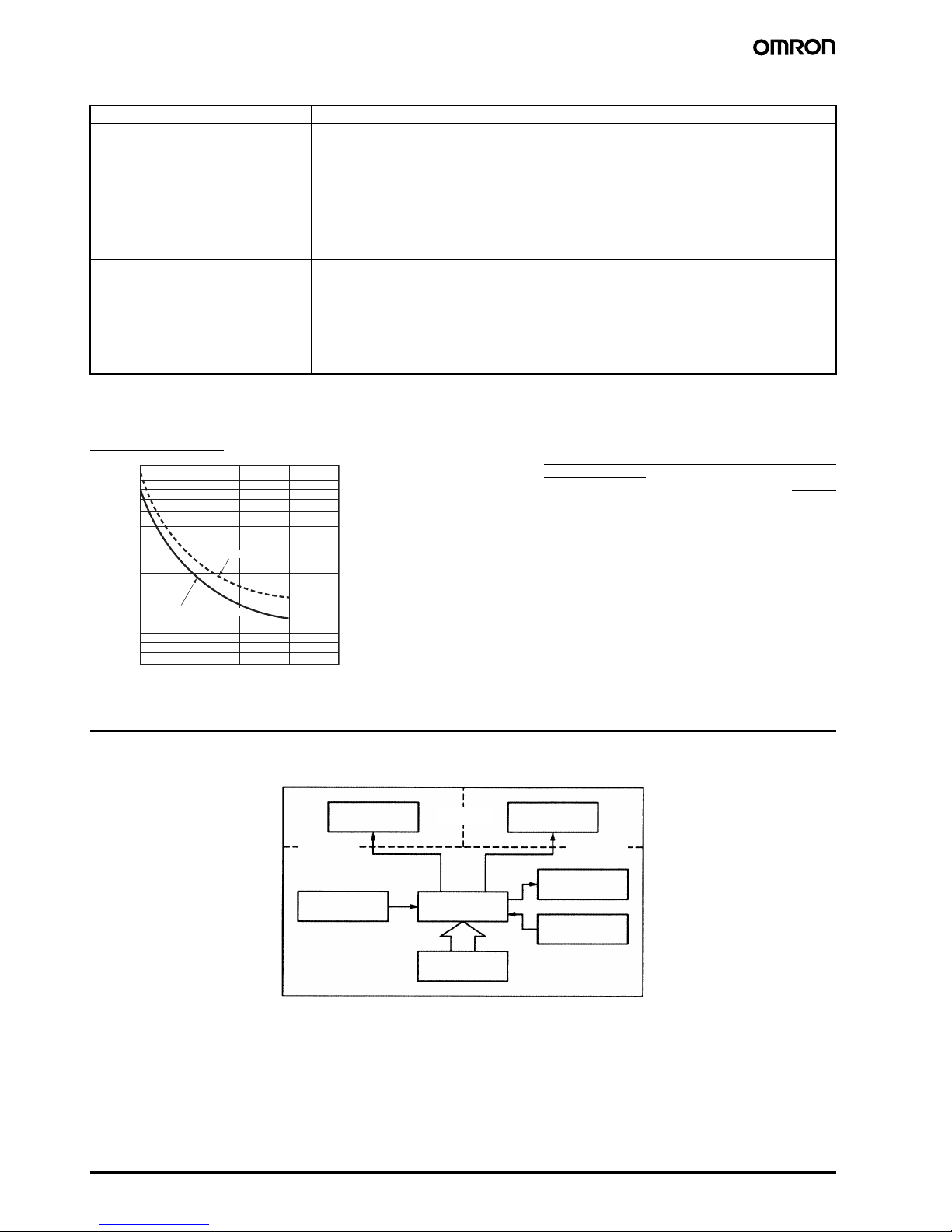
Connections
■ Block Diagram
Transmission path connections Multidrop
Communications method RS-485 (two-wire, half duplex)
Synchronization method Start-stop synchronization
Baud rate (See note.) 1,200/2,400/4,800/9,600 bit/s
Transmission code ASCII
Data bit length (See note.) 7 or 8 bits
Stop bit length (See note.) 1 or 2 bits
Error detection (See note.) Vertical parity (none, even, or odd) (See note.)
Block check character (BCC)
Flow control Not supported.
Interface RS-485
Retry function Not supported.
Communications buffer 40 bytes
Reading and writing from H8GN Reading present value and totalizing count value; reading/writing preset and set values; switching be-
tween SV-banks; switching between communications write-enabled/write-prohibited; reading/writing
other initial and advanced function setting parameters
1,000
700
500
300
100
70
50
01 2 3
4
30 VDC (cosφ = 1)
250 VAC (cosφ = 1)
Switching operations (×10
3
)
Load current (A)
Input circuit
Output circuit
Display circuit
Communications
circuit
(Functional
insulation)
(Basic
insulation)
(Basic
insulation)
Internal
control circuit
Power supply
circuit
Key switch
circuit
Page 5
Preset Counter/Timer H8GN C-63
Counters
■ I/O Functions
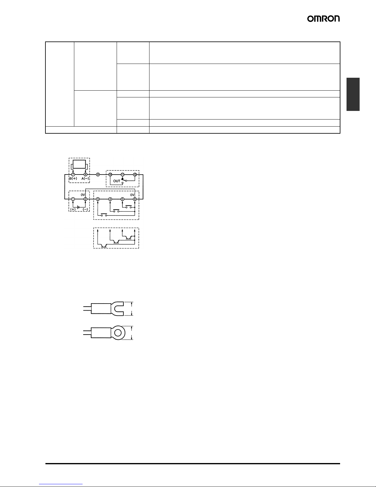
■ Terminal Arrangement
Note: (2) and (6) are connected internally.
Do not use unused terminals as relay terminals.
Note: *Recommended power supply; eg. OMRON S8VS
■ Wiring
Use the following type of crimp terminals for M3 screw.
Inputs Counter inputs CP1/CP2 • Receive count signals.
• Receive increment, decrement, individual, and quadrature inputs.
• In increment mode and decrement mode, CP1 is used for the count input and CP2 is used
for count prohibit input.
Reset • Resets the present value. (Totalizing count value is not reset.)
(In increment mode or increment/decrement mode, the present value returns to 0; in Decrement Mode the present value returns to the set value.)
• The count input is not received during resetting.
• The RST indicator is lit during resetting.
Timer inputs Start • Starts timing.
Reset • Resets the timer. (In elapsed time mode the time returns to 0; in remaining time mode, the
time returns to the set value.)
• During resetting, timing stops and the control output turns OFF.
• The RST indicator is lit during resetting.
Gate • Prohibits timing operation.
Outputs OUT • Output made according to the output mode setting when the set value is reached.
RS-485
Communications*
Contact inputs
Output
Open-collector inputs
*Only models with communications
Reset
Not
connected
CP1/
Start
CP2/
Gate
24-VDC
power supply*
5.8 mm max.
5.8 mm max.
Page 6
C-64 Preset Counter/Timer H8GN
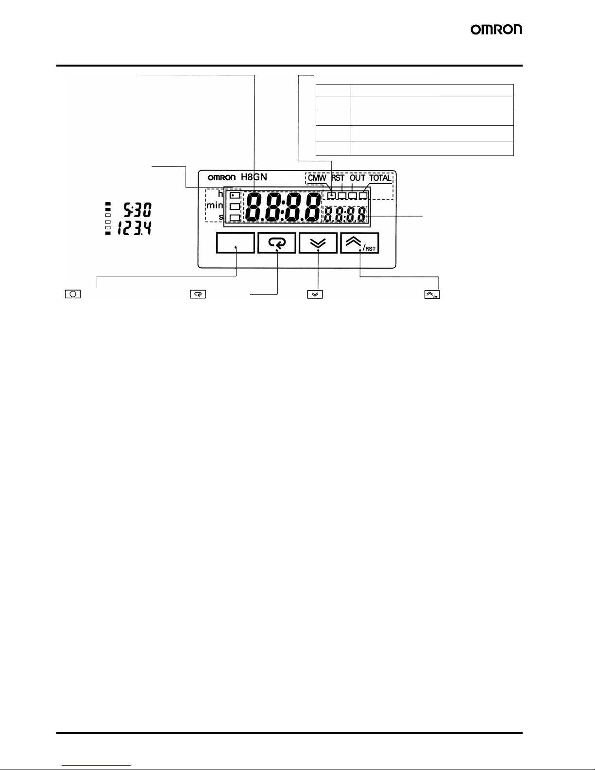
Nomenclature
CMW
RST
OUT
TOTAL
Operation display 2
5 h 30 min
123.4 s
Level Key Mode Key
Down Key
Up/Reset Key
Indicator Meaning
Lit when communications writing is enabled.
Lit during reset using reset input or Reset Key.
Lit when control output is ON.
Lit when totalizing count value is displayed.
Example
No. 1 Display
Displays the present value or parameter type.
When totalizing count is displayed, the
leftmost 4 digits of the 8-digit totalizing count
will be displayed. (Zeros suppressed)
Operation display 1
Displays the time unit when the
timer function has been selected.
Flashes while timer is on 0.0 min,
0 h 00 min, 0.0 h, or 0 h.
Press this key to select the setup
level. The setup level is selected in
order "operation level" ←→
"adjustment level", "initial setting
level" ←→ "communications setting
level".
Press this key to select
parameters within each
level.
Each press of this key decreases
values displayed on the No. 2
display. Hold down this key
continuously to decrease values
quickly. Also returns setting
items.
Each press of this key
increases values
displayed on the No. 2
display. Hold down this
key continuously to
increase values quickly.
Also advances setting
items.
Reset Function
To reset the present
value, press this key
while the present value
is displayed.
If this key is pressed
while the totalizing
count value is
displayed, the totalizing
count value and the
present value will be
reset.
No. 2 Display
Displays set value or
set value of the
parameter.
Displays the
rightmost 4 digits of
the count value (8
digits) when the
H8GN is used as a
totalizing counter.
(Zeros suppressed)
Page 7
Preset Counter/Timer H8GN C-65
Counters
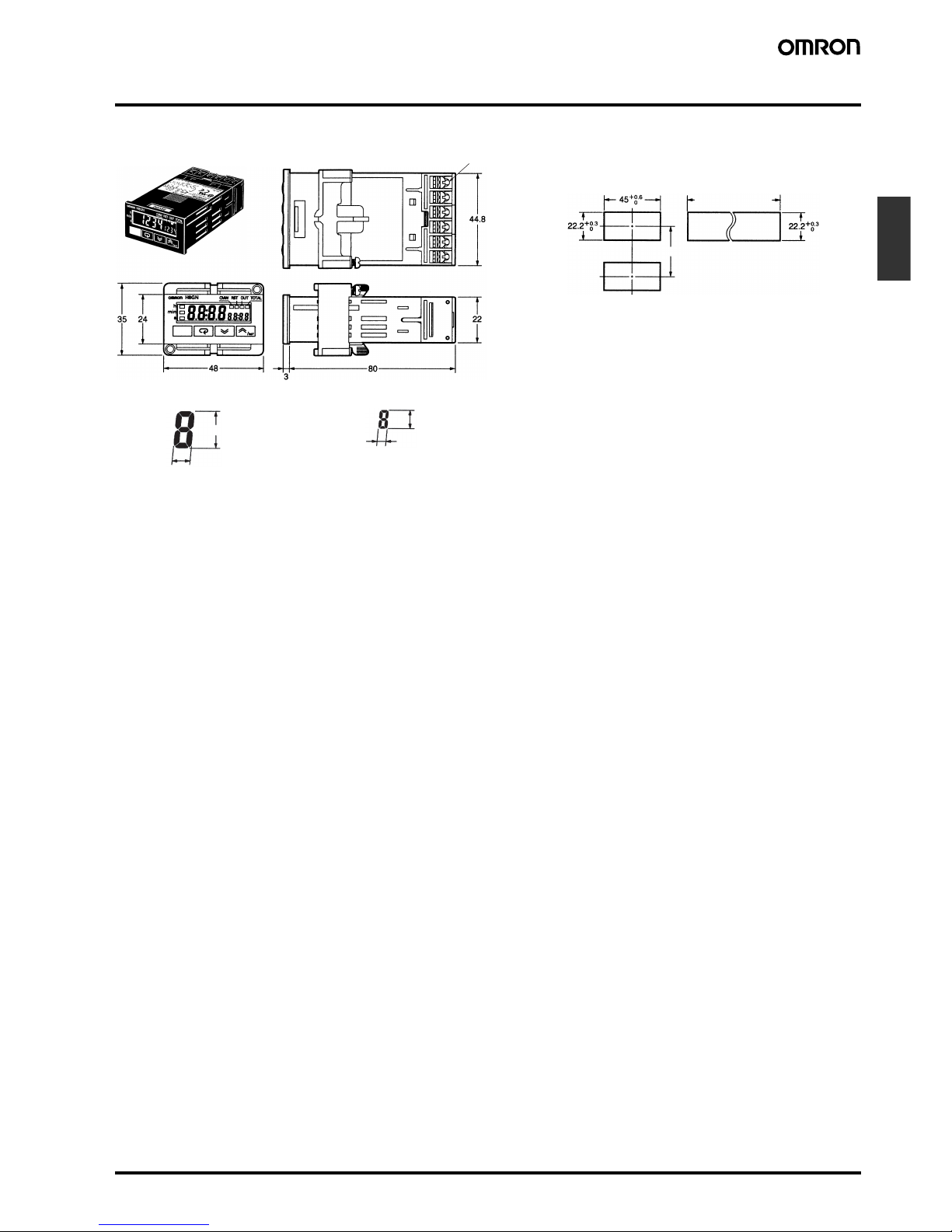
Dimensions
Note: All units are in millimeters unless otherwise indicated.
7 mm
3.3 mm
3.4 mm
1.6 mm
No. 1 display digit size
Panel cutout
Gang mounting
40 min.
H8GN
No. 2 display digit size
Separate
mounting
0
(48 × No. of units
− 2.5)
+1.0
The product cannot
be made waterproof
when gang-mounted.
• Insert the H8GN in the square cutout,
insert the adapter from the back, and
push the H8GN into the cutout as far
as possible. Use screws to secure the
H8GN. To make the H8GN waterproof,
insert waterproof packing and tighten
the screws.
• When mounting two or more products
in a cutout, be sure that the ambient
temperature does not exceed the
specifications.
M3 terminal screw
Page 8
C-66 Preset Counter/Timer H8GN
Precautions
!Caution
Do not use the product in locations subject to flammable or explosive gases. Doing so may result in explosion.
!Caution
The service life of the output relays depends on the switching capacity and switching conditions. Consider the actual application
conditions and use the product within the rated load and electrical
service life. Using the product beyond its service life may result in
contact deposition or burning.
!Caution
Do not disassemble, repair, or modify the product. Doing so may
result in electric shock, fire, or malfunction.
!Caution
Do not allow metal objects or conductive wires to enter the product. Doing so may result in electric shock, fire, or malfunction.
Other Precautions
• Store at the specified temperature. If the H8GN has been stored at
a temperature of less than −10°C, allow the H8GN to stand at room
temperature for at least 3 hours before use.
• Use the product within the ratings specified for vibration, shock,
submerging in water, and exposure to oil.
• Do not use the product in locations subject to dust, corrosive
gases, or direct sunlight.
• Use the product within the ratings specified for temperature and
humidity.
• The product is designed for 24 VDC. Applying voltages other than
the rated one such as 100 to 240 VAC may damage the internal
elements.
• Separate the input signal devices, input signal cables, and the
product from the source of noise or high-tension cables producing
noise.
• Separate the product from the source of static electricity when
using the product in an environment where a large amount of static
electricity is produced (e.g., forming compounds, powders, or fluid
materials being transported by pipe).
• Do not expose the product to organic solvent such as thinner or
benzine, strong alkali materials, or strong acid materials. Doing so
may damage the product surface.
Application Precautions
1. Do not use the product in locations where condensation may
occur due to high humidity or where temperature changes are
severe.
2. Be sure to wire terminals correctly, with the correct polarity.
3. Maintain the power supply voltage within the allowable ranges.
4. Connect the power supply through a relay or switch so that the
voltage reaches a fixed value immediately. If the voltage
increases gradually the power supply may be reset or outputs
may turn ON.
5. When the power is turned ON, an inrush current (approx. 15 A)
will flow momentarily. Depending on power supply capacities, the
product may not start due to this leakage current. The power supply must be of a sufficiently large capacity.
6. For the main power supply or the power supply for input devices,
use a power supply transformer whose primary side is insulated
from the secondary side and whose secondary side is not
grounded.
7. Leaving the H8GN with outputs ON at a high temperature for a
long time may hasten the degradation of internal parts (such as
electrolytic capacitors). Therefore, use the product in combination
with relays and avoid leaving the product as long as more than 1
month with the output turned ON.
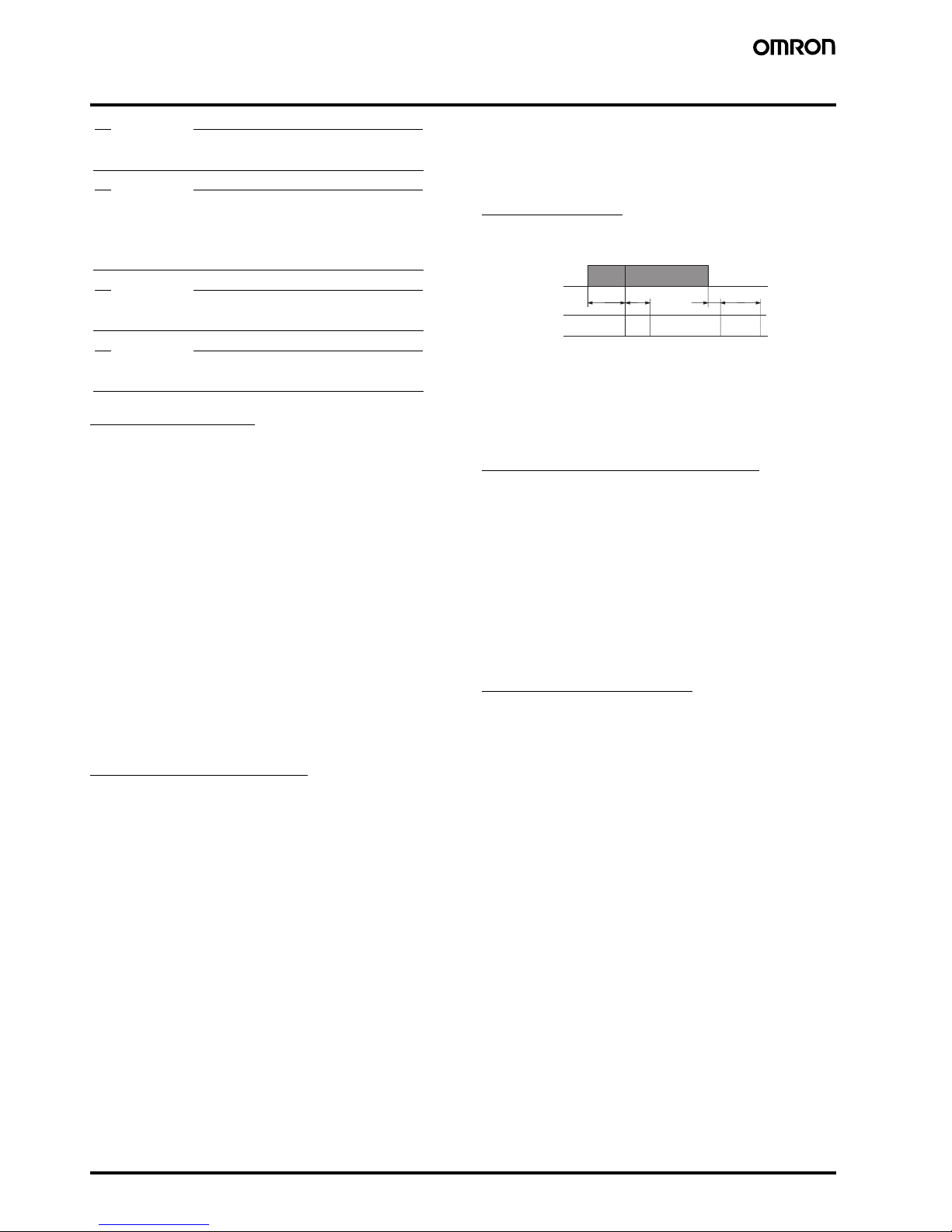
Power Supplies
When turning the power ON and OFF, input signal reception is possible, unstable, or impossible as shown in the diagram below.
Turn the power ON and OFF using a relay with a rated capacity of
15 A minimum to prevent contact deterioration due to inrush current
caused by turning the power ON and OFF.
When power is turned ON, a starting current flows momentarily.
Therefore, pay attention to the overcurrent detection level of the
power supply used.
Timer Control with Power Start
To allow for the startup time of peripheral devices (sensors, etc.), the
H8GN starts timing operation between 210 to 260 ms after power is
turned ON (see diagram above). For this reason, in operations where
timing starts from power ON, the time display will actually start from
258 ms. If the set value is 258 ms or less, the time until output turns
ON will be a fixed value between 210 and 260. (Normal operation is
possible for set value of 259 ms or more.) In applications where a set
value of 258 ms or less is required, use start timing with signal input.
When the H8GN is used with power start in F mode (i.e., accumulative operation with output on hold), there will be a timer error (approximately 100 ms each time the H8GN is turned ON) due to the
characteristics of the internal circuitry. Use the H8GN with signal
start if timer accuracy is required.
Changing the Set Value
In Counter Operation
When changing the set value during operation, the output will turn
ON if the set value equals the present value.
In Timer Operation
When changing the set value during operation, if the set value is
changed in so that the conditions below are satisfied, the Timer operates in the same way as when the present value reaches the set
value because a constant read-in system is in use. Depending on the
output mode, this may result in output turning ON.
Timer mode UP: Present value ≥ set value
Timer mode DOWN:Elapsed time ≥ set value
(Present value = 0)
Note: When in DOWN mode, the amount set value is changed is add-
ed to or subtracted from the present value.
210 ms
5 ms
Input Impossible
Unstable
Possible ImpossibleUnstable
0 to 50 ms 0 to 500 ms
ON
OFF
Power
supply
Page 9

Preset Counter/Timer H8GN C-67
Counters
Operation with a Set value of 0
In Counter Operation
The output will turn ON if the set value (0) equals the present value.
The output will be OFF while the Reset Key is pressed or the reset
input is ON.
In Timer Operation
a) When the output mode is set to A, B (one-shot output), D, or F,
output will turn ON when the start signal is input.
b) When the output mode is set to B (hold output), E, or Z, output will
remain OFF even when the start signal is input.
Response Delay Time When Resetting
The following table shows the delay from when the reset signal is
input until the output is turned OFF.
Output Delay Time
The following table shows the delay from when the timer value
passes the set value until the output is produced.
Actual Measurements in N or K Mode
*The variation in delays is due to different modes and conditions.
Mounting
Tighten the two mounting screws on the Adaptor. Tighten them alternately, a little at a time, so as to keep them at an equal tightness.
The H8GN’s panel surface is water-resistive (conforming to NEMA
4X (indoors) and IP66). In order to prevent the internal circuit from
water penetration through the space between the Counter and operating panel, attach a rubber packing (provided with the H8GN)
between the Counter and operating panel and secure the rubber
packing with the Y92F-34 Flush-mounting Adaptor.
Output
The SPDT (single-pole, double-throw) consists of an SPST-NO contact and an SPST-NC contact. Do not form a circuit with 3-point
short-circuit (power short-circuiting with arc).
Reference
For details about communications functions, refer to H8GN Preset
Counter/Timer User’s Manual (Catalog No. M066).
Minimum reset signal width Output delay time
1 ms 3.7 to 6.0 ms
20 ms 19 to 21 ms
Control output Max. counting
speed
Output delay time*
Contact output 30 Hz 17.3 to 18.9 ms
5 kHz 3.5 to 5.2 ms
Adaptor
Waterproof packing
Panel
Power supply
Short-circuit current
Page 10

C-68 Preset Counter/Timer H8GN
Operating Procedures
■ Initial Setup
The and Keys are used to switch between setup menus, and the amount of time that you hold the keys down for determines which setup
menu you move to. This section describes two typical examples.
Note: In the following sections, “PV” is used to indicate a present value and “SV” to indicate a set value.
1. Using the H8GN as a Counter
Typical Application Examples
Typical Application
• Setup Procedure
1. Changing Set Values
2. Displays
No. 1 display No. 2 display
Power ON Power ON
Operation Level
Set input mode
Set output mode
Set SV
Reset PV
Start operation
Operate
Operation Level
Initial Setting Level
Check the counting speed.
Check the input signal width.
Input signal width:
Counting speed:
Output mode:
Input mode:
Function:
Press the Key.
PV:
PV/SV:
Input mode Individual input
Output mode F (overcount)
Counting speed 30 Hz
Input signal width 20 ms
Decimal point None
Prescale None
• Confirming Set Values
Set value and selections in each
display can be changed by pressing
the and Keys.
Present value (PV)/
set value (SV)
Press the Level Key for at
least 3 s. Operation stops.
Check Counter/
Timer selection
Check counting
speed
Check input
signal width
Check Counter/Timer
selection
Use the and
Keys to set the input mode
to individual mode.
Use the and
Keys to set the output mode
to F.
Press the Level Key for at
least 1 s.
Operation starts.
Press the and
Keys to change the set
value to 100.
Set values are effective two seconds after key operation is stopped or when the
or Key is pressed.
Page 11

Preset Counter/Timer H8GN C-69
Counters
2. Using the H8GN as a Timer
Typical Application Examples
Typical Application Examples
1. Changing Set Values
2. Display
No. 1 Display No. 2 Display
Power ON
Power ON
Operation Level
Set time range
Check timer mode
Check output mode
Check output time
Set SV
Reset PV
Operate
Operation Level
Initial Setting Level
Check the output mode.
Check the output time.
Output time:
Output mode:
Timer mode:
Time range:
Function:
Press the Key.
PV:
PV/SV:
Time range 0.0 to 999.9 s
Timer mode DOWN (remaining time)
Output mode A mode
Output time Hold
Input signal width 20 ms
Check the input signal width.
Input signal width:
Start operation
• Setup Procedure
• Confirming Set Values
Set value and selections in each
display can be changed by pressing
the and Keys.
Present value (PV)/
set value (SV)
Press the Level Key for at
least 3 s. Operation stops.
Set Counter/Timer
selection
Check input signal
width
Use the and
Keys to select the timer
function.
Use the and
Keys to set the time range to
999.9 s
Use the and
Keys to set the timer mode to
remaining time.
Press the Level Key for at
least 1 s. Operation starts.
Use the and
Keys to set the SV to 10.0.
Set values are effective two seconds after key operation is stopped or when the
or Key is pressed.
Page 12

C-70 Preset Counter/Timer H8GN
■ Setting Specifications after Turning ON Power
Outline of Operation Procedure
Key Operation
In the following descriptions, all the parameters are introduced in the display sequence. Some parameters may not be displayed depending on the
protection settings and operating conditions.
Note: Of these levels, the initial setting level, communications setting level, and advanced function setting level can be used only when operation
has stopped. Control output is stopped when these three levels are selected. When switched back to the operation level from one of these
levels, operation will start.
Description of Each Level
Operation Level
• This level is displayed when you turn the power ON. You can move
to the protect level, initial setting level, and adjustment level from
this level.
• Normally, select this level during operation.
• During operation, the present value, set value, totalizing count
value, and setting number of SV-bank can be monitored using the
Key.
Adjustment Level
• To select this level, press the Key once for less than one sec-
ond.
• This level is for entering set value (SV 0 to 3) for operation. This
level contains parameters for communications writing enable/disable, set value of SV-bank, and cycle time (timer Z mode).
• You can move to the top parameter of the operation level, protect
level, or initial setting level from here.
Initial Setting Level
• To select this level, press the Key for at least three seconds in
the operation level or adjustment level.
• This level is for selecting the function, input mode, time range, timer
mode, output mode, output time, counting speed, input signal
width, decimal point position, prescale value, and rising/falling edge
for input signal.
• You can move to the advanced function setting level or communica-
tions setting level from this initial setting level. To return to the operation level, press the Key for at least one second. To move to
the communications setting level, press the key once for less
than one second.
Protect Level
• To select this level, simultaneously press the and Keys
for at least three seconds (default value). This level is to prevent
unwanted or accidental modification of parameters. Protected levels will not be displayed, and so the parameters in that level cannot
be modified.
Communications Setting Level
• To select this level, press the Key once for less than one sec-
ond in the initial setting level. When the communications function is
used, set the communications conditions in this level. Communicating with a personal computer (host computer) allows set values to
be read and written.
Advanced Function Setting Level
• To select this level, you must change the initial settings/communica-
tions protection setting in the protect level to “0” and then enter the
password (“−169”) in the initial setting level.
• This level is for initializing settings, enabling SV-bank and totalizing
counter use, setting display auto-return time, and move- to-protectlevel time.
• You can move to the initial setting level from this level.
+
+
Power ON
Operation level
Adjustment level
Protect level
Operation stops
Initial setting level
Keys 1 s. min.
Password input set value "−169"
Keys
3 s. min. (default value)
Key
less than 1 s.
Key
1 s. min.
Key
3 s min.
Communications
setting level
Key
less than 1 s.
Key
1 s. min.
Advanced function
setting level
Operation in progress
Operation stopped
Not displayed depending on model and settings.
Not displayed depending on model and settings.
Level change
Page 13

Preset Counter/Timer H8GN C-71
Counters
Parameters
Operation Level
1. PV/SV
This display appears when the power is turned ON. No. 1 display
shows the present value and No. 2 display shows the set value.
The values displayed will be determined by the settings for
Counter/Timer selection, time range, timer mode, and decimal
point position made in the initial setting level.
Use the and Keys to change the settings.
2. PV
No. 1 display will show the present value and No. 2 display will
remain blank. The values displayed will be determined by the settings for Counter/Timer selection, time range, timer mode, and
decimal point position made in the initial setting level.
Press the Key to reset the present value.
3. Totalizing Count Value
The totalizing count value is displayed only if “totalizing
counter used” in the advanced function setting level has
been set to ON.
The leftmost four digits of the 8-digit totalizing count value will be
shown in No. 1 display and the rightmost four digits will be shown
in No. 2 display.
Refer to Input/Output Mode Settings on page page 79 for information on totalizing counter operation.
4. SV-bank (m-sp)
SV-bank is displayed only when “SV-bank used” in the
advanced function setting level has been set to ON.
Select the SV-bank (SV 0 to 3). To use the SV-bank function, the
four set values (SV 0 to 3) can be set beforehand in the adjustment level. The keys on the front of the Unit can then be used during operation to switch between the set values. For models with
built-in communications, communications can be used to switch
between the set values.
Adjustment Level
1. Communications Writing Control (cmwt)
Communications writing control is displayed only for models
with communications.
Allows or prohibits communications to write data from a personal
computer (host computer). Communications can be used to read
data regardless of this setting.
2. SV 0 to 3 (sp-0, sp-1, sp-2, sp-3)
SV 0 to 3 is displayed only when “SV-bank used” in the
advanced function setting level has been set to ON.
Used to set the set value when the SV-bank function is used. The
operator can use the keys on the front to switch between the set
values (SV 0 to 3). When the set value is changed in operation
mode, the set value (SV 0 to 3) set in the adjustment level for SVbank will also change.
3. Cycle Time (cyti)
Cycle time is displayed only when the “output mode for timer
function” in the initial setting level has been set to “Z.”
Sets the cycle time used for ON/OFF-duty adjustable flicker mode
(Z). Cyclic control can be performed easily in ON/OFF-duty
adjustable flicker mode by first setting the cycle time in the adjustment level and by using the set value in operation level to change
the ON-duty ratio.
Refer to Input/Output Mode Settings on page 80 for information
on ON/OFF-duty adjustable flicker mode operation.
(1) PV/SV
(2) PV
(3) Totalizing count value
(4) SV-bank
0→1→2→3→0→1→2→0→1→2
0→1→2→3→3→4→5→0→1→2
TOTAL
=Totalizing count value: 12,345,687
PV
Totalizing count value
Press the Key to simultaneously reset the
totalizing count value and the present value.
Key
during PV
display
Key during
totalizing count
value display
SV
Switch between SV
(1) Communications writing control
(2) SV 0
(2) SV 1
(2) SV 2
(2) SV 3
(3) Cycle time
ON duty (%)
Control output
Cycle time
Close Open
Cycle time passed
Val ve
ON duty 0% to 100%
Controlling the flowrate by opening and closing the
electromagnetic valve by pulse control.
Set ON duty rate
as a percentage
ON duty can be changed like an analog input
by using the Up and Down Keys.
Fully closed to
fully open
Page 14

C-72 Preset Counter/Timer H8GN
Initial Setting Level
1. Counter/Timer Selection (func)
Select to use the H8GN as either a counter or a timer.
2. Input Mode (cntm)
The input mode is displayed only when “Counter/Timer
selection” in the initial setting level has been set to counter.
When the H8GN is to be used as a counter, select increment,
decrement, individual, or quadrature for the input mode. If increment or decrement is selected, the input signal edge for CP1
(count input) can be switched using the input signal edge setting.
Refer to Input/Output Modes and Count Values on page 78 for
information on input mode operations.
3. Time Range (timr)
The time range is displayed only when “Counter/Timer selection” in the initial setting level has been set to timer.
When the H8GN is to be used as a timer, set the time range to be
timed.
4. Timer Mode (timm)
The timer mode is displayed only when “Counter/Timer
selection” in the initial setting level has been set to timer.
When the H8GN is to be used as a timer, set the elapsed or
remaining time mode.
5. Output Mode for Counter Function (outm)
The output mode is displayed only when “Counter/Timer
selection” in the initial setting level has been set to counter.
When the H8GN is to be used as a counter, set the output mode.
Refer to Input/Output Mode Settings on page 79 for information
on output mode operations.
6. Output Mode for Timer Function (outm)
The output mode is displayed only when “Counter/Timer
selection” in the initial setting level has been set to counter.
When the H8GN is to be used as a timer, set the output mode.
Refer to Input/Output Mode Settings on page 79 for information
on output mode operations.
7. Output Time (otim)
The output time is displayed only when “output mode for
counter function” in the initial setting level has been set to C
or K or when “output mode for timer function” in the initial
setting level has been set to A or B.
When using one-shot output in the H8GN, set the output time for
the one-shot output (0.01 to 99.99 s).
One-shot output can be used only when the C or K output mode
is selected for counter function or A or B output mode is selected
for timer function.
If the output time is set to “0” when selecting timer function, the
output will be held. The output time cannot be set to “0” for
counter function.
8. Counting Speed (cnts)
The counting speed is displayed only when “Counter/Timer
selection” in the initial setting level has been set to counter.
When the H8GN is used as a counter, the operator can switch
between maximum counting speeds (30 Hz/5 kHz) for CP1 and
CP2.
Set to 30 Hz when using a contact for the input signal. When the
counting speed is set to 30 Hz, input signal chattering is removed.
9. Input Signal Width (iflt)
Switches between minimum input signal widths (20 ms/1 ms) for
start, reset and gate inputs. All input signal widths are set
together via external input.
When the counter function is selected, only the reset input is set,
but when the timer function is selected the start, gate, and reset
inputs are all set together.
Set to 20 ms when using a contact for the input signal. When the
input signal width is set to 20 ms, input signal chattering is
removed.
10.Decimal Point Position (dp)
The decimal point position is displayed only when “Counter/
Timer selection” in the initial setting level has been set to
counter.
This determines the decimal point position for PV, SV, SV-bank
(SV 0 to 3), and totalizing count values. Press the Key to
move the decimal point to the left and press the Key to move
it to the right.
11.Prescale Value (pscl)
The prescale value is displayed only when “Counter/Timer
selection” in the initial setting level has been set to counter.
Converts the counter input pulse to any value within the setting
range (0.001 to 9.999).
Example: To have a display of @@.@@ m for a system that outputs 25 pulses when the object has been moved forward 0.5 m,
perform the following steps.
1. Set the decimal point position to before the second-last digit.
2. Set the prescale value to 0.02 (0.5 ÷ 25).
(1) Counter/Timer selection
(2) Input mode
(3) Time range
(4) Timer mode
(5) Output mode for counter function
(6) Output mode for timer function
(7) Output time
(8) Counting speed
(9) Input signal width
(10) Decimal point position
(11) Prescale value
(12) Input signal edge
(13) Move to advanced function setting level
Encoder
25 pulses
Page 15

Preset Counter/Timer H8GN C-73
Counters
12.Input Signal Edge (edge)
The input signal edge will be displayed only when the “input
mode” at the initial setting level has been set to increment or
decrement.
Switches the CP1 input edge when the H8GN is used as an incrementing or decrementing counter. In the counter increment or
decrement modes, CP2 will function as the gate input and CP1
counting will be prohibited while CP2 is ON.
Refer to Input/Output Modes and Count Values on page 78 for
information on input mode operations.
13.Move to Advanced Function Setting Level (amoU)
This will be displayed only when the “initial setting/communications protection” in protect level is set to 0.
This setting enables the advanced function settings to utilize the
counter/timer functions to the maximum. To move to the
advanced function setting level, enter the password (−169) from
the initial setting level.
Page 16

C-74 Preset Counter/Timer H8GN
Advanced Function Setting Level
1. Parameter Initialization (init)
Used to return all settings to default values.
Turn ON parameter initialization and shift to another display to
return all settings to default values.
2. SV-bank Used (nspu)
Set “SV-bank used” to ON and operate the keys from the panel to
switch between SV 0 to 3.
To use the SV-bank function, the set value (SV 0 to 3) must be set
beforehand in the adjustment level. These set value are then
used during operation by operating the keys on the front of the
Unit.
3. Totalizing Counter Used (tcnu)
Set totalizing counter use to ON to display and enable use of the
totalizing counter in the operation level.
The totalizing counter displays the leftmost four digits of the 8digit totalizing count on No. 1 display and the rightmost four digits
on No. 2 display to enable 8-digit counting.
4. Display Auto-return Time (ret)
If this function is used, the display in the operation and adjustment
levels will automatically return to the PV/SV display if no key operations have been made for the set period. (setting range: 1 to
99 s.)
The time before auto-return of the display can be set here. If this
setting is set to OFF, the auto-return function will not operate.
5. Move-to-protect-level Time (prlt)
If the and Keys are pressed for more than 3 seconds
in the operation level, the display will move to the protect level.
Use this setting to change the time that the key must be pressed
to any time within the setting range (3 to 30 s).
Protect Level
1. Operation/Adjustment Protection (oapt)
The following table shows the protection given for each setting
level.
Not protected: Display and setting changes are possible.
Display only: Display is possible.
No display, no level shift: Display and level shifts are not possible.
The initial setting level is 0 and no protection is given at this setting level.
2. Initial Setting/Communications Protection (icpt)
Moving to initial setting, communications setting, or advanced
function setting levels is restricted.
OK: Move to other levels possible
NO: Move to other levels not possible
The default setting is 1.
3. Setting Change Protection (wtpt)
Restricts setting changes using front panel keys.
The default setting is OFF.
4. Reset Key Protect (rpt)
Prohibits the use of the Reset Key.
The default setting is OFF.
(1) Parameter initialization
(2) SV-bank used
(3) Totalizing counter used
(4) Display auto-return time
(5) Move-to-protect-level time
Setting level Operation level Adjustment
level
PV/SV Other
0 Not protected Not protected Not protected
1 Not protected Not protected No display,
no level shift
2 Not protected No display,
no level shift
No display,
no level shift
3 Display only No display,
no level shift
No display,
no level shift
Setting Initial setting
level
Communications
setting level
Advanced
function
setting level
0OK OK OK
1OK OK NO
2NO NO NO
Setting Meaning
OFF Settings can be changed by key operation.
ON Settings cannot be changed by key operation.
(Only protect level settings can be changed.)
Setting Meaning
OFF PV and totalizing count values can be reset by the
Reset Key.
ON PV and totalizing count values cannot be reset by
the Reset Key.
(1) Operation/Adjustment Protection
(2) Initial Setting/Communications Protection
(3) Setting Change Protection
(4) Reset Key Protection
Restricts use of the Reset Key.
Restricts menu display and writing in the
operation and adjustment levels.
Restricts menu display and moving to the
initial setting level/communications setting
level/advanced function setting level.
Restricts setting changes using front panel
keys.
Page 17

Preset Counter/Timer H8GN C-75
Counters
Communications Setting Level
The communications specifications are set in the communications
setting level. Make the individual communications settings from the
front panel.
The communications parameters and their settings are listed in the
following table.
Note: 1. The settings shown in reverse video are the default settings.
2. Settings made in the communications setting level are en-
abled when the power is turned ON again.
Before performing communications, perform the following procedure
with the front panel keys to set the communications unit number,
baud rate, and other settings. Refer to the communications manual
for operation methods for other communications settings.
1.Press the Key for at least 3 seconds and move from the
operation level to the initial setting level.
2.Press the Key and move from the initial setting level to the
communications setting level.
3.Press the Key to change the settings items as shown
below.
4.Use the and Keys to change the settings data.
Align each communications setting with the settings on the personal
computer or other communications device.
1. Communications Unit Number (u-no)
When communicating with a host computer, set a unit number to
enable the host computer to identify each unit. The number can
be set in a range from 0 to 99 in increments of 1. The default unit
number is 1. When using multiple units, the units will not function
normally if the same unit number is set for more than one unit.
2. Baud Rate (bps)
Set the baud rate for communications with the host computer. The
settings correspond to the following baud rates.
1.2 (1,200 bps), 2.4 (2,400 bps), 4.8 (4,800 bps), and 9.6
(9,600 bps).
3. Communications Data Length (len)
The communications data length can be changed to either 7 or 8
bits.
4. Stop Bits (sbit)
The stop bits can be set to either 1 or 2.
5. Parity (prty)
The parity can be set to none, even, or odd.
Parameter Display Settings Set value
Communications
unit number
u-no 0 to 99
Baud rate bps 1.2, 2.4,
4.8, or 9.6
(kbps)
Communications
data length
len 7/8 (bits)
Stop bits sbit 1/2
Parity prty None,
even, or
odd
0 / 1
99
to
1.2 / 2.4 / 4.8 / 9.6
7
/ 8
1
/ 2
none
/ euen /
odd
(1) Communications unit number
(2) Baud rate
(3) Communications data length
(4) Stop bits
(5) Parity
Page 18

C-76 Preset Counter/Timer H8GN
■ Parameters
+
+
: N
: F
: C*
: K*
: A*
: B*
: D
: E
: F
: Z
Counting
speed
: 30 Hz
: 5 kHz
: 20 ms
: 1 ms
: 0
: 0.0
: 0.00
: 0.000
Power ON
Operation level
Protect level
Keys 1 s. min.
Advanced function setting level
: 3 to 30 s.
Key 1 s. min.
Initial setting level
Key 1 s. min.
Key 3 s. min.
Key 1 s. min.
Operation level
Key less than 1s.
Power ON
PV/SV
PV
SV-bank
See note 1.
See note 2.
See note 3.
Move to advanced function setting level.
Counter
Timer
: 0.01 to 99.99 s
: 0.00 to 99.99 s
: 0.001 to 9.999
Adjustment
level
Key
less than 1 s.
Key
1 s. min.
Key
3 s. min.
Initial
setting
level
Key
less than 1 s.
Communications
setting level
Key
1 s. min.
Password input
set value "−169"
Advanced
function setting
level
Operation in progress
Operation stopped
No display due to model and settings
No display due to model and settings
Level change
Keys
3 s. min. (default value)
Press the Key to
reset the PV.
Press the Key to reset
the totalizing count value and
the PV simultaneously
Totalizing
count value
When
totalizing
counter
selected
When
using
SV-bank
: SV 0
: SV 1
: SV 2
: SV 3
Parameter
initialization
Use SVbank
Use
totalizing
counter
Display
auto-return
time
Move-toprotectlevel time
When
counter
selected
: Initialize
: Not initialize
: Use
: Not use
: Use
: Not use
: No auto-return
: 1 to 99 s.
Note : The parameters shown in reverse video are
the default settings.
Password input
(−169) and move
Counter/
Timer
selection
: Counter
: Timer
When
counter
selected
Input
mode
: Increment
: Decrement
: Individual
: Quadrature
When
timer
selected
Time
range
Timer
mode
: Elapsed time
: Remaining time
When
counter
selected
Output
mode for
counter
When
timer
selected
Output
mode for
timer
When the
above C*,
K*, A*, or
B* mode
selected
Output
time
Output will be held if output time is 0.
Output time cannot be set to 0 when
counter function is selected.
When
counter
selected
Input signal
width (start,
reset, gate)
When
counter
selected
Decimal
point
position
Prescale
value
: Counting on rising edge
: Counting on falling edge
When
increment
or
decrement
selected in
counter
input mode
Input
signal
edge
Page 19

Preset Counter/Timer H8GN C-77
Counters
+
/
: -.---s
: ----h
: ---.-h
: --h--min
: ---.-min
: --min--s
: ----s
: ---.-s
+
Adjustment level
Cycle time
SV 3
SV 2
SV 1
SV 0
See note 1.
See note 1.
See note 1.
See note 1.
See note 1.
Key for more than set time (The default setting is 3 s.)
Key for 1 s. min.
Protect level
Communications setting level
Baud rate
Stop bits
Pari ty
: 0 to 99
Note: 1. Counter (increment or decrement)
: −999 to 9999
Counter (individual or quadrature)
Timer (cycle time or mode other than output mode Z)
: 0 to 9999
Timer (output mode Z)
: 0% to 100% (ON duty)
2. Time range
: --.--s (default)
Models with
communications
Communications
writing
: Enabled
: Disabled
When using
SV-bank
When timer
output mode
Z is selected
: Level 0
: Level 1
: Level 2
: Level 3
: Level 0
: Level 1
: Level 2
Operation/
adjustment
protection
Initial
settings/
communications
protection
: No key-operated
setting changes
: Key-operated setting
changes allowed
Setting
changes
protection
: Reset Key disabled
: Reset Key enabled
Reset Key
protect
: 0.000 to 9.999 s
: 0.00 to 99.99 s
: 0.0 to 999.9s, min, h
: 0 to 9999 s, h
: 0 min 00 s to 99 min 59 s
: 0 h 00 min to 99 h 59 min
3. Displayed when level 0 is selected for initial setting/
communications protection in the protect level.
Communications
Unit No.
Data
length
Models with
communications
: 1,200 bps
: 2,400 bps
: 4,800 bps
: 9,600 bps
: 7 bits
: 8 bits
: 1 bit
: 2 bits
: None
: Eve n
: Odd
Note : Settings made in the communications
setting level are enabled when the power
is turned ON again.
Page 20

C-78 Preset Counter/Timer H8GN
■ Operating Mode
Input/Output Modes and Count Values
Note: 1. (A) indicates the minimum signal width and (B) requires at least 1/2 the minimum signal width. If these conditions are not met, a counting
error (+1 or −1) may occur.
2. The following table explains the L and H symbols in the above graphics.
Up (Increment) mode (up) Down (Decrement) mode (down)
Input
edge
UP
DOWN
CP1: Count input CP2: Count prohibit input
Count
Count
prohibit
n
n-1
n-2
n-3
n-4
n-5
CP1: Count input CP2: Count prohibit input
Count
Count
prohibit
CP1: Count input CP2: Count prohibit input
Count
Count
prohibit
n
n-1
n-2
n-3
n-4
n-5
CP1: Count input CP2: Count prohibit input
Count
Count
prohibit
Up/Down B Individual input (ud-b)
Count
Up/Down C quadrature input (ud-c)
Count
Symbol Input
H Short-circuited
L Open
Page 21

Preset Counter/Timer H8GN C-79
Counters
Input/Output Mode Settings
Counter Function
Note: 1. t: output time. t − a < t : Less than the output time.
2. If there is a power failure during output ON, output will turn ON again when the power supply has recovered. For one-shot output, an
output will be made again for the duration of the output time setting once the power supply has resumed.
3. Output timing restarted during one-shot outputs is ignored.
Totalizing Counter Operation
Input mode
Up Down Up/Down B.C
Output
mode
N
F
C
K
9999
0
−
999
Reset
SV
Output
9999
0
−
999
Reset
SV
Output
9999
0
−
999
tt t
Reset
SV
Output
t t-a t
tt t
9999
0
−
999
t-a t t-a
Reset
SV
Output
t-a
t
t-a t
• Totalizing counter continues to count the present
value, regardless of whether an reset input (by the
reset key) has been made to reset the PV.
• When totalizing count value is reset, the PV is
reset at the same time.
• The totalizing count range is 0 to 99,999,999. If the
totalizing count exceeds 99,999,999, the count
returns to 0. If the count drops below 0, it becomes
99,999,999.
Reset
PV
Totalizing
count reset
(reset key)
Totalizing
count value
Page 22

C-80 Preset Counter/Timer H8GN
Timer Function
Z Mode
Output quantity can be adjusted by changing the cycle time set in the adjustment level to 1 and by changing the ON duty (%) set value.
The set value shows the ON duty (%) and can be set to a value between 0 and 100 (%). When the cycle time is 0, the output will always be OFF.
When the cycle time is not 0 and when ON duty has been set to 0 (%), the output will always be OFF. When ON duty has been set to 100 (%), the
output will always be ON.
A mode: Signal ON-delay (See note.) B mode: Flicker (See note.)
D mode: Signal OFF-delay E mode: Interval
F mode: Accumulative Z mode: ON/OFF-duty adjustable flicker
0
0
Start
Gate
Reset
SV
DOWN
UP
SV
Timer display
Power
supply
Control
output
0
0
Start
Gate
Reset
SV
DOWN
UP
SV
Timer display
Power
supply
Control
output
0
0
Start
Gate
Reset
SV
DOWN
UP
SV
Timer display
Power
supply
Control
output
0
0
Start
Gate
Reset
SV
DOWN
UP
SV
Timer display
Power
supply
Control
output
0
0
Start
Gate
Reset
SV
DOWN
UP
SV
Timer display
Power
supply
Control
output
0
0
Start
Gate
Reset
DOWN
UP
Cycle time
Cycle time
Timer display
Power
supply
Control
output
ON duty setting
(%) ON time
ON duty setting
(%) ON time
Note: One-shot output or HOLD output can be selected for output:
Cycle time
ON duty (%)
Cycle time
Control output
Page 23

Preset Counter/Timer H8GN C-81
Counters
■ Troubleshooting
When an error occurs, the error code is displayed on the main display. Take countermeasures according to the code.
Note: Error codes are displayed only if PV/SV or PV is being displayed.
No. 1 display No. 2 display Error contents Countermeasure
e111 No display Memory error (RAM) Turn the power OFF and ON again. If normal operation is still not restored,
it may be necessary to repair or replace the H8GN. If normal operation is
restored by turning the power supply OFF and ON, it is possible that there
is noise interference. Check that there is nothing in the vicinity that may be
the source of noise.
e111 sum Memory error (EEP)
e1 No display CPU error
- - - -
Flashes
Set value displayed or
no display
Present value underflow
This is not an actual error. This display indicates that the present value has
dropped to a value less than −999. Reset using reset input or pressing the
Up Key when “- - - -” is displayed.
Page 24

C-82 Preset Counter/Timer H8GN
Additional Information
■ Parameters List
Fill in your set values in the Set value column of the following tables and utilize the tables for quick reference.
Protect Level
Operation Level
Parameter name Parameter Setting range Default
value
Unit Set value
Operation/Adjustment Protection oapt 0 to 30
Initial Setting/Communications Pro-
tection
icpt 0 to 21
Setting Change Protection wtpt on/off off
Reset Key Protection rpt on/off off
Parameter name Parameter Setting (display) range Default
value
Unit Set value
Present value (PV)/
Set Value
(SV)
PV Counter -999 to 9999/---- (PV<-999) 0
Timer 0.000 to 9.999 (Time range=-.---s) 0.000 Second
0.00 to 99.99 (Time range=--.--s) 0.00 Second
0.0 to 999.9 (Time range=---.-s) 0.0 Second
0 to 9999 (Time range=----s) 0 Second
0:00 to 99:59 (Time range=--min--s) 0:00 Minute:
Second
0.0 to 999.9 (Time range=---.-min) 0.0 Minute
0:00 to 99:59 (Time range=--h--min) 0:00 Hour:
Minute
0.0 to 999.9 (Time range=---.-h) 0.0 Hour
0 to 9999 (Time range=----h) 0 Hour
SV Counter 0 to 9999 (Input mode=Up or Down) 0
-999 to 9999 (Input mode=Individual or quadrature) 0
Timer (Output mode:
A, B, D, E,
F)
0.000 to 9.999 (Time range=-.---s) 0.000 Second
0.00 to 99.99 (Time range=--.--s) 0.00 Second
0.0 to 999.9 (Time range=---.-s) 0.0 Second
0 to 9999 (Time range=----s) 0 Second
0:00 to 99:59 (Time range=--min--s) 0:00 Minute:
Second
0.00 to 999.9 (Time range=---.-min) 0.0 Minute
0:00 to 99:59 (Time range=--h--min) 0:00 Hour:
Minute
0.00 to 999.9 (Time range=---.-h) 0.0 Hour
0 to 9999 (Time range=----h) 0 Hour
Timer (Output mode:
Z)
0 to 100 0 %
PV Same as for PV in the above PV/SV column.
Totalizing count value 0 to 99999999 0
SV-bank m-sp 0/1/2/30
Page 25

Preset Counter/Timer H8GN C-83
Counters
Adjustment Level
Initial Setting Level
Communications Setting Level
Parameter name Parameter Setting range Default
value
Unit Set value
Communications writing
control
cmwt on/off off
SV 0 sp-0 Same as for PV in the above PV/SV column.
SV 1 sp-1 Same as for PV in the above PV/SV column.
SV 2 sp-2 Same as for PV in the above PV/SV column.
SV 3 sp-3 Same as for PV in the above PV/SV column.
Cycle time Timer (Out-
put mode=Z)
cyti 0.000 to 9.999 (Time range=-.---s) 0.000 Second
0.00 to 99.99 (Time range=--.--s) 0.00 Second
0.0 to 999.9 (Time range=---.-s) 0.0 Second
0 to 9999 (Time range=----s) 0 Second
0:00 to 99:59 (Time range=--min--s) 0:00 Minute: Sec-
ond
0.0 to 999.9 (Time range=---.-min) 0.0 Minute
0:00 to 99:59 (Time range=--h--min) 0:00 Hour: Minute
0.0 to 999.9 (Time range=---.-h) 0.0 Hour
0 to 9999 (Time range=----h) 0 Hour
Parameter name Parameter Setting range Default
value
Unit Set value
Counter/Timer selection func cn t/tim cnt
Input mode cntm up/down/ud-b/ud-c up
Time range timr -.---s/--.--s/---.-s /----s/
--min--s/---.-min/--h--min/
---.-h ----h
--.-- Second
Timer mode timm up/down up
Output mode for counter
function
outm n/f/c/kn
Output mode for timer function
outm a/b/d/e/f/=a
Output time Counter o tim 0.01 to 99.99 0.50 Second
Timer 0.00 to 99.99 0.00 Second
Counting speed cnts 30h=/s kh= 30h=
Input signal width iflt 20ms/1ms 20ms
Decimal point position dp ----/---.-/--.--/-.--- ----
Prescale value pscl 0.001 to 9.999 1.000
Input signal edge edge up /down up
Move to function setting lev-elamou -999 to 9999 0
Parameter name Parameter Setting range Default
value
Unit Set value
Communications unit number
u-no 0 to 99 1
Baud rate bps 1.2/2.4/4.8/9.6 9.6 kbps
Communications data
length
len 7/87bit
Stop bits sbit 1/22bit
Parity prty none/eUen/odd eUen
Page 26

C-84 Preset Counter/Timer H8GN
Advanced Function Setting Level
Parameter name Parameter Setting range Default
value
Unit Set value
Parameter initialization init on/off off
SV-bank used mspu on/off off
Totalizing counter used tcnu on/off off
Display auto-return time ret off/1 to 99 off Second
Move-to-protect-level time prlt 3 to 30 3 Second
In the interest of product improvement, specifications are subject to change without notice.
ALL DIMENSIONS SHOWN ARE IN MILLIMETERS.
To convert millimeters into inches, multiply by 0.03937. To convert grams into ounces, multiply by 0.03527.
Cat. No. M065-E1-02
 Loading...