

Page 1
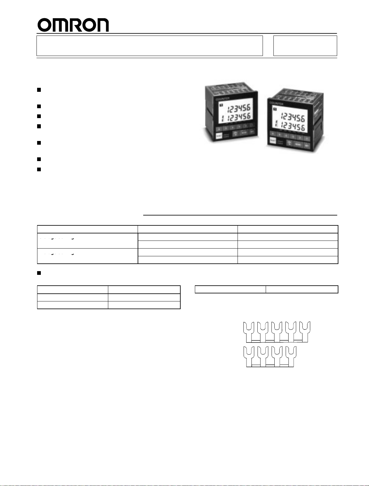
Multi-maintenance Counter H8BM
3 s age se g
s age se g
Nine Built-in Counters/Timers to
Measure Equipment Utilization
Up to nine Counters can be used as counters or
accumulative timers.
Can be used as a multi-stage preset counter.
Individual outputs to indicate maintenance timing.
Pre-forecast/Forecast and machine stoppage
output provided.
IP54F enclosure rating for resistance to oil and
water.
Compact, short-body: 72 x 72 x 79 mm (DIN).
Directly connectable to 2-wire DC sensors.
Ordering Information
RC
Number
3-stage setting
1-stage setting
of stages
NPN H8BM-B
PNP H8BM-BP
NPN H8BM-BD
PNP H8BD-BDP
Accessories (Order Separately)
Replacement Parts
Name Model
Hard Protective Cover Y92A-72C
Rubber Packing
A
Hard Protective Cover and Rubber Packing are
Counter.
Y92S-25
supplied with the
Output Model
Short
Bar
Short
Bar
When the Counter is used as a multi-stage preset counter, wiring
will be facilitated if Counter inputs 1 through 9 are short-circuited
with
the following Short Bar
5-pole
4-pole
Both
the 5-pole and 4-pole Short Bars are used to short-circuit the 9
Counter
inputs.
Y92S-26
.
1
Page 2
H8BM
Specifications
Item H8BM-B, H8BM-BP H8BM-BD, H8BM-BDP
Classification
Mounting method
External connections
Enclosure ratings
Display mode
Output mode
Reset system
T
iming function
Input signal method
Control output No-contact outputs: NPN outputs (RUN, forecast,
Display
LCD with backlight Yes
Built-in counter number
Number of stages
Digits
Max. time settings
Memory backup
Approved standards
3-stage setting 1-stage setting
Flush mounting
Screw terminals
IP54F (panel surface)
Up display
F mode
External, manual resets
Yes
V
oltage inputs: High and low signal voltages (count, reset, re-monitor
machine stoppage) (PNP outputs for -BP)
Count, preset value, counter number
reset, I/O inhibit, and re-monitor modes displayed on LCD characters
Output indication on LCD characters and LEDs
9 (counters 1 to 9) (see Note 1)
3 stages (see Note 2)
Forecast value:
Pre-forecast value:
Machine stoppage:
Forecast value:
Pre-forecast value:
Machine stoppage:
Backup time for power interruption: Approx. 10 years at 25
UL508, CSA C22.2 No.14
6 digits (999999)
–5 digits (see Note 3)
+5 digits (see Note 4)
99999.9 hr (0.1 hr or more)
–9999.9 hr (see Note 3)
+9999.9 hr (see Note 4)
, and error codes displayed on 7-segment LCD Power-ON, mode,
H8BM
, counter select, I/O inhibit)
No-contact outputs: NPN outputs (RUN, forecast)
(PNP outputs for -BDP)
1 stage (see Note 5)
6 digits (999999)
99999.9 hr (0.1 hr or more)
°C
Note: 1.
Each channel operates on an separate I/O.
2. Pre-forecast:
Forecast:
Machine stoppage:
3.
The pre-forecast value is set as a negative offset in respect to the forecast value.
4.
The machine stoppage value is set as a positive of
5.
This model operates on the forecast value only
Ratings
Rated
voltage
Operating voltage range
Power consumption
Max. counting speed
Min. input signal width
One-shot output time
Count, reset, re-monitor
output number request, and
I/O inhibit input
Control output
Case color
Note: 1.
Ripple content: 20% max.
2.
On power application, an inrush current of approx. 1.2 A flows into the Counter
3.
This signal is output as a carry signal when the Counter is used as a totalizing counter
This signal can also be used as a no-voltage input signal depending on the wiring (refer to Input Connections).
4.
,
Displayed only on LCD (No external output is provided.)
Displayed on LCD and LED and output (Output for each Counter)
Displayed on LCD and LED and output
(Output when the count value of one or more of Counters 1 to 9 has reached its machine stoppage value.)
fset in respect to the forecast value.
.
24 VDC
85% to 1
Approx. 1.8 W (at 24 VDC) (see Note 2)
30 cps (ON:OFF = 1:1)
Counter No. selection input:
Reset input:
Re-monitor input:
Output number request input:
I/O inhibit input:
20 ms (see Note 3)
V
High level:
Low level:
Open-collector output: 100 mA max. at 30 VDC max.
Light gray (Munsell 5Y3/1)
10% of rated voltage (see Note 1)
16.7 ms max.
100 ms max.
30 ms max.
30 ms max.
16.7 ms max.
oltage input (see Note 4) (input resistance: approx. 2.2 k
16 to 30 VDC
0 to 3 VDC
.
Ω)
.
2
Page 3
H8BM
Characteristics
Insulation
Dielectric strength
Impulse withstand voltage
Noise immunity
Static immunity
V
ibration resistance
Shock resistance
Ambient temperature
Ambient humidity
Weight
resistance
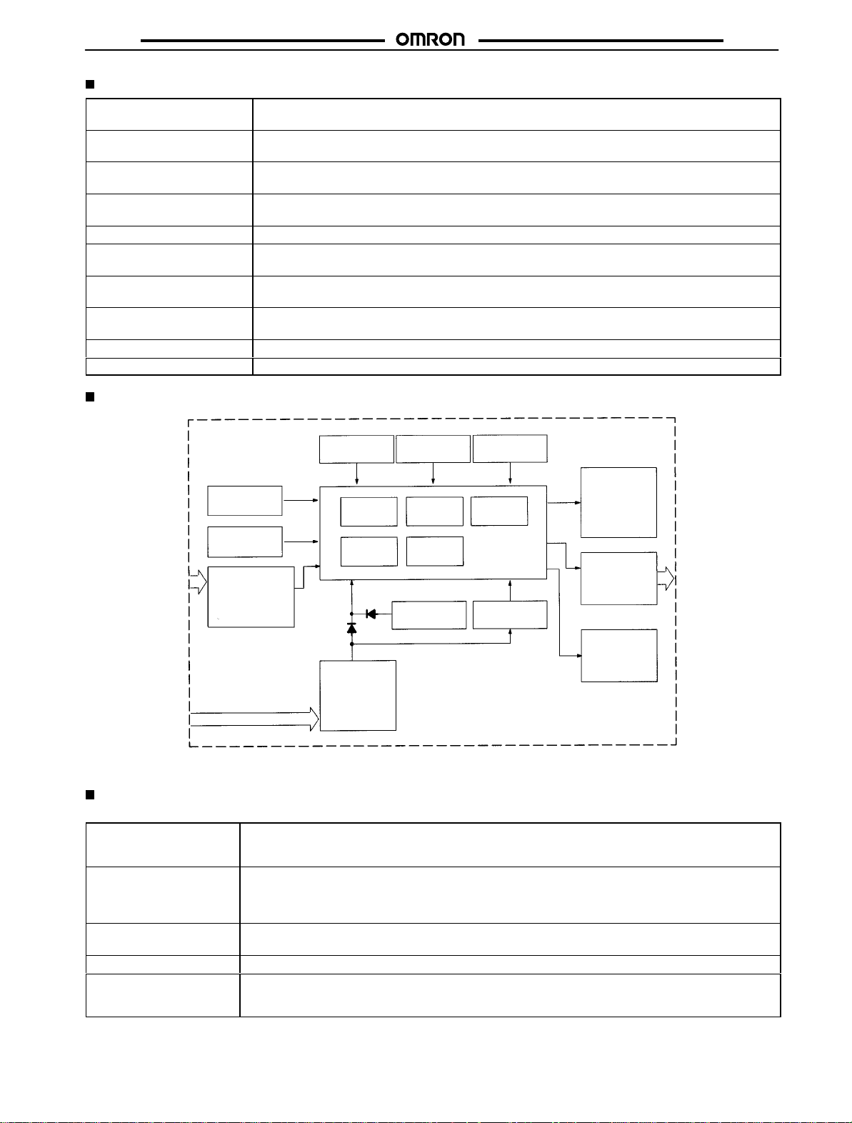
Block Diagram
H8BM
100 MΩ min. (at 250 VDC) (between current-carrying terminals and exposed non-current-carrying
metal parts)
1,000 V
AC, 50/60 Hz for 1 min (between current-carrying terminals and exposed non-current-carrying
metal parts)
1 kV (between power terminals)
1.5 kV (between current-carrying terminals and exposed non-current-carrying metal parts)
±
1 kV (between power terminals) and ±600 V (between input terminals), square-wave noise via noise
simulator (pulse width: 100 ns/1
Malfunction: 8 kV
Destruction:
Malfunction:
Destruction:
Malfunction:
Operating: –10°
Storage: –25°
; destruction: 15 kV
10 to 55 Hz with 0.75 mm single amplitude in three directions
10 to 55 Hz with 0.5 mm single amplitude in three directions
2
294 m/s
2
196 m/s
C to 55°C (with no icing)
C to 65°C (with no icing)
Operating: 35% to 85%
Approx. 290 g
µs, 1-ns rise)
Although
the input terminals are electrically insulated from the internal circuit, do not conduct
I/O Functions
Inputs
Count
(1 to 9)
Reset
Re-monitor
Counter No. select
I/O inhibit
Function
setting circuit
Key switch
circuits
Input circuits
(count 1 to 9,
reset, re-monitor,
output number
request, I/O inhibit)
(DC) input
Counter clock
generator
ROM RAM LCD driver
Count
circuits
Power circuits*
System clock
generator
Count
circuits
Battery
LCD reference
voltage generator
One-chip
microcomputer
Power failure
detector
LCD
Output circuits
(Output 1 to 9,
RUN, machine
stoppage)
LED
an insulation resistance test on these terminals.
Input count values.
Used as time count input signals when Counter is used as timer
.
Maximum counting speed: 30 Hz (minimum signal width: 16.7 ms)
Resets displayed count (timing) value of a specified Counter
Counter under reset does not operate ad its output is turned OFF
.
.
Reset signal input during re-monitor input restores reset count (timing) value of the specified Counter
While reset signal is ON, RST indicator lights.
Reset count (timing) value of specified Counter can be re-monitored, and restored by reset input.
While re-monitor signal is ON, RCV indicator lights.
Specifies Counter whose count (timing) value is to be displayed.
Inhibits count inputs of all Counters.
T
urns OFF all forecast outputs, RUN outputs, and machine stoppage outputs.
While I/O inhibit signal is ON, INHB indicator lights.
.
3
Page 4
H8BM
Outputs
Forecast (1 to 9)
RUN T
Machine stoppage
Each of these outputs turns ON when its forecast value has been reached.
When Counter is used as totalizing counter
, output one-shot signals as carry signals.
Retain outputs until count values are reset.
urns ON when Counter is operating normally
T
urns ON when count value of one Counter has reached set machine set machine stoppage value.
.
Retains output until count value is reset.
H8BM
Note: The
input and output signals are enabled when power is applied to the Counter
and
the output signals are turned OFF
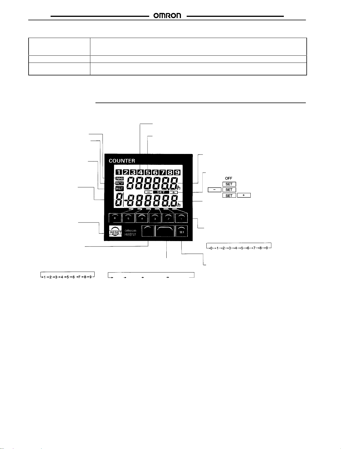
Nomenclature
I/O Inhibit Indicator
Indicates that the input/output
inhibit input signal is ON.
Re-monitor Input Indicator
Indicates that the re-monitor
input signal is ON.
Reset Input Indicator
Indicates that the reset input
signal is ON.
Counter No. Indicator
Indicates the number of the
Counter whose data (count
value, preset value, etc.) is
currently displayed.
RESET Key
Resets the count value
and output signals.
COUNTER No. Key
Selects the Counter in
sequence each time this
Selector is pressed: (Any
Counter whose forecast value
is set to 0 is skipped in the
RUN mode.)
RUN
.
The following indicators light to show that the count value has reached
the preset value and that the output has turned OFF.
Control Output Indicator (Red LED):
Pre-forecast value: LCD lights
Forecast value: RED LED lights
Control Output Indicator (LCD):
Machine stoppage value: Indicator flashes between red and green
CNT
MODE
No.
MODE Key
Selects the mode in sequence each time
this key is pressed:
Forecast
value
Pre-forecast
value
Machine
stoppage
value
. During a power failure, the input signals are disabled,
and LCD output indicator flashes.
Count Value
Indicates the current count (current time in
timer mode)
Set Mode Indication
Preset Value
Always indicates the forecast value during
the RUN operation. Indicates the set
value in each setting mode.
Up Keys 1 to 6
Each of these keys increments the preset
value of the corresponding digit, each
time it is pressed.
SET Key
Inputs the set or changed data.
: RUN mode
: Forecast value
: Pre-forecast value
: Machine stoppage value
Note: Models with only 1-stage setting (H8BM-jDj) are not provided with pre-forecast
forecast output function is provided.
4
and machine stoppage output function; only the
Page 5

H8BM
Operation
H8BM
Operation
1. Selecting Counter/Timer Operation
Whether
each Counter operates as a counter or a timer can be spe
cified on a DIP switch provided on the side panel of the Counter.
Open
the lid of the switch compartment on the side of the Counter
Set
each DIP
figure:
The setting of the DIP switch is read on power application.
Note: The setting of the DIP switch that is used to select the
2. Changing Mode
Each
switch pin as necessary by referring to the following
Timer
Counter
or timer operation of each Counter is read on power
counter
application. Setting change of this DIP switch while the
Counter
is operating will be ignored. Power must be turned
off
then back on again after changing settings.
DIP switch compartment
time the MODE Key is pressed, the mode changes as follows:
Note: 1. The modes marked * are not provided on the 1-stage
Counter
-
type
.
2. I/O operations are always performed regardless of the
.
mode.
3. If
no key is pressed for 1 minute in each mode, the RUN
mode
is automatically restored.
3. Setting/Changing Data (3-stage Type)
Setting/Changing
1. Press the MODE Key to enter the forecast value setting
mode. The same Counter number as in the RUN mode is
displayed.
2. Press the COUNTER No. Key to select the Counter whose
data is to be set or changed. The Counters are selected in
sequence each time the COUNTER No. Key is pressed. A
Counter can also be selected by inputting the Counter No.
selection.
Forecast V
alue
RUN mode
Forecast value mode
Mode
Key
Pre-forecast value mode*
Mode
Key
Mode
Key
Mode
Key
RUN
Mode Indication
Forecast Value Setting
Mode Indication
Flashing
Pre-forecast V
Setting Mode Indication
Flashing
Machine Stoppage V
Setting Mode Indication
alue
alue
Flashing
3. Use the Up Keys (1 to 6) to change the values of the digits.
When an Up Key is pressed, the corresponding digit starts
flashing.
The preset value is zero-suppressed. Each time the
Up
Key is pressed, the specified value increment as:
Flashing
In
the following example, the forecast value
to
35000.
of Counter 2 is set
Machine stoppage mode*
Flashing
Flashing
5
Page 6

H8BM
H8BM
4. Press the SET Key to determine the set value. If o Key is
pressed within 5 seconds after the SET Key has been
pressed,
the RUN mode is automatically restored. Key inputs
made
during the 5 seconds are valid.
After the set forecast value has flashed, the display is
changed
automatically as below
RUN Mode Indication
.
4. Resetting Count Value
Resetting Value for Each Counter
1. Select
the Counter whose count value is to be reset by either
pressing the COUNTER No Key or inputting the Counter No.
select.
The count value can be reset in any mode.
5. Re-monitoring Count Value
A
count value that has been reset by mistake can e recovered. (ex.
Recover
previously reset count value “23456” of Counter No. 3)
1. Turn ON the re-monitor input. The count value which was
reset will be displayed. At this time, the count value is only
displayed and not recovered internally. The Counter whose
count
value is displayed remains in the RUN mode.
2. Press the COUNTER No. Key (or apply the Counter No.
3. Press the RESET Key (or apply the reset input). The
input) to access the Counter whose count value
select
recovered.
the
recovered value will flash 3 times, and the count value that
was
While
remain displayed. However, the internal mechanism of the
Counter will continue operating from the count value before
resetting.
If the count value does
following operations are not necessary
reset will be recovered
the
recovery input is ON, the recovered count value will
not need to be recovered,
.
for the designated Counter only
is to be
.
2. Either press the RESET Key or input the reset signal. The
value of the selected Counter will be reset to 0.
count
6
4. Turn
OFF the re-monitor input to restore normal operation.
6. Checking Count Values (RUN Mode)
Select
the Counter whose count value is to be checked by pressing
the COUNTER No. Key in the RUN mode, or by inputting the
Counter No. select. The Counter number changes in sequence
each time the COUNTER No. Key is pressed. However, any
Counter
not
used (whose forecast value is set to 0) will be skipped.
Page 7

H8BM
H8BM
7. Count Value Display
While the count input is ON, the period on the count value display
flashes.
The timer operation
of
the count input.
measures time by totaling the ON time
8. Output Indicator
The
status of the pre-forecast,
puts
is displayed as follows:
1. Pre-forecast:
has
reached the pre-forecast value is displayed on the LCD.
The
pre-forecast is only displayed on LCD as
no
actual output is issued.
2. Forecast
the
Counter whose count value is displayed on the LCD.
The number of the Counter whose count value
Output:
forecast, and machine stoppage out
a message and
A red indicator lights above the number of
9. Clearing Settings
• The count values of all the Counters can be cleared by
simultaneously holding down the RESET Key and COUNTER
No. Key for 3 seconds.
The
same
and
function is ef
reset input are simultaneously applied for 3 seconds.
fected if the Counter number select input
• The count value, pre-forecast value, forecast value, and
machine stoppage value of all the Counters can be cleared by
simultaneously holding down the RESET and SET Keys for 3
seconds.
10. When Used as Totalizing Counter/Timer
Counter
By
setting the forecast value of a Counter to 999999 (99999.9 hr),
the
Counter can be used as a totalizing
stoppage
izing
output for 20 ms as a carry signal when the count value changes
from
output
counter
999999 to 0.
of this Counter is not issued. When used as a total
, the forecast output of this Counter issues a one-shot
counter/timer
11. Self-diagnostic Function
The
following displays will appear if an error occurs.
Display Meaning Output
E1 CPU
Error
E2 Memory
Error
status
OFF Press
Recov-
ery
RESET
Key
Normal counter
operation is
recovered using
count and set
values from
before the error
Factory setting
. The machine
-
Setting after
recovery
.
3. Machine Stoppage Output: The background alternately
lights
in red and green, and the number of the Counter whose
machine
Flashing
Note: When
stoppage output is issued is flashed on the LCD.
any of the pre-forecast, forecast,
page outputs of a Counter has turned ON, the Counter
number of that Counter is automatically displayed. When
an
attempt to reset the count value is made at this time, the
count
value of only
rently displayed is reset (in RUN mode only).
the Counter whose count value is cur
and machine stop
-
-
7
Page 8

H8BM
Timing Charts
H8BM
Counter (3-stage Preset Operation)
Reset input
Count input
Machine stoppage value
Count value
Pre-forecast indicator
output and indicator
999999
Forecast value
Pre-forecast value
Forecast output
and indicator
Machine stoppage
0
Totalizing Counter Operation
Reset input
Count input
999999
Count value
Forecast output
(indicator)
0
One-shot output time: 20 ms
Timer (3-stage Preset Operation)
Reset input
Count input
Machine stoppage value
Time value
99999.9 hr
Forecast value
Pre-forecast value
Pre-forecast indicator
Machine stoppage
output and indicator
0.0 hr
Forecast output
and indicator
Totalizing Timer Operation
Reset input
Count input
99999.9 hr
Time value
0.0 hr
Forecast output
(indicator)
One-shot output time: 20 ms
Dimensions
Note: All
Panel Cutouts
Panel cutout is as shown below (according to DIN43700). The
mounting
units are in millimeters unless otherwise indicated.
panel thickness should be 1 to 5 mm.
Hard Protective
Cover (transparent)
8
Page 9

H8BM
Installation
Mounting
To
mount the Counter
to the left and right sides of the
ries
knurled
screws on the brackets. If any other screws are used to at
tach
the brackets, or if the knurled screws are excessively tightened
with
a tool, damage may result.
Hard Protective
Cover (transparent)
, attach the two fixtures supplied as accesso
Rubber packing
Counter
Mounting bracket
Mounting
panel
, and securely tighten the
(2 sets)
Knurled screw
H8BM
-
Provide
enough space around the Counter when mounting it to en
a proper working space.
sure
-
Other components
-
Terminal Arrangement
22 23 24 25 26 27 28
15 16 17 18 19 20 21
8 9 10 11 12 13 14
12 3 4 5 6 7
22 23 24 25 26 27 28
Reset
input
Count No.
selection
15 16 17 18 19 20 21
Re-monitor
input
8 9 10 11 12 13 14
RUN
output
1 2 3 4 5 6 7
Power
supply: 0 V
I/O inhibit
input
Machine
stoppage
output
Power
supply:
24 V
Count
input 1
Count
input 6
Forecast
output 1
Forecast
output 6
Count
input 2
Count
input 7
Forecast
output 2
Forecast
output 7
Count
input 3
Count
input 8
Forecast
output 3
Forecast
output 8
Count
input 4
Count
input 9
Forecast
output 4
Forecast
output 9
Count
input 5
Input COM
Forecast
output 5
Output
COM
9
Page 10

H8BM
Connections
NPN Output
H8BM
Count input 1
Note: Short-circuit
Count input 2
Count input 3
Count input 4
Count input 5
Count input 6
Count input 7
Count input 8
Count input 9
Count No.
selection
Reset input
I/O inhibit input
Re-monitor input
INPUT COM
16 to 30 VDC
terminals 1 and 7 when the power source of the Counter is shared.
DISPLAY
Count value
Setting value
Count up
6 digit, 3-stage
preset Counter
x 9
5 V
H8BM-BD/-BDP outputs the forecast and machine stoppage values simultaneously
RUN, machine stoppage,
forecast outputs 1 to 9
Load
Power
circuit
.
Forecast output 1
Forecast output 2
Forecast output 3
Forecast output 4
Forecast output 5
Forecast output 6
Forecast output 7
Forecast output 8
Forecast output 9
Machine
stoppage output
RUN output
OUTPUT COM
+24 V
0 V
+10%
24 VDC
–15%
Load
Load
Load
Load
Load
Load
Load
Load
Load
Load
Load
* Connect
a diode to suppress Counter surge when an inductive
load is connected.
Note: When
damaged.
30 VDC
Max.
the load is short-circuited, the internal circuits may be
10
Page 11

H8BM
PNP Output
H8BM
16 to 30 VDC
Note: H8BM-BD/-BDP
Count input 1
Count input 2
Count input 3
Count input 4
Count input 5
Count input 6
Count input 7
Count input 8
Count input 9
Count No.
selection
Reset input
I/O inhibit input
Re-monitor input
INPUT COM
DISPLAY
Count value
Setting value
Count up
6 digit, 3-stage
preset Counter
x 9
5 V
Power
circuit
outputs the forecast and machine stoppage values simultaneously
OUTCOM
All outputs
Load
30 VDC
Max.
OUTPUT COM
Forecast output 1
Forecast output 2
Forecast output 3
Forecast output 4
Forecast output 5
Forecast output 6
Forecast output 7
Forecast output 8
Forecast output 9
Machine
stoppage output
RUN output
24 VDC
.
+24 V
0 V
+10%
–15%
Load
Load
Load
Load
Load
Load
Load
Load
Load
Load
Load
* Connect
a diode to suppress Counter surge when an inductive
load is connected.
Note: When
the load is short-circuited, the internal circuits may be
damaged.
Output
Output method
Applicable voltage
Rated current
Residual voltage
Leakage current
I/O Connections
Input Circuits
INCOM
Input
The
1.2 kΩ
430 Ω
1.2 kΩ
input terminals are electrically
insulated from the internal circuits.
Photocoupler
RUN,
Open collector
30 V max.
100 mA
2 V max.
100 µA max.
5 V
machine stoppage, forecast 1 to 9
Output Circuits
NPN Type
10 Ω
39 V
OUTCOM*
The
OUT COM and 0 V terminals
are internally connected.
Output
PNP Type
39 V
10
OUTCOM
Output
Ω
11
Page 12

H8BM
Example of Input Connections (Solid-state Switches)
Two-wire
The
put, and re-monitor input signals are enabled when voltage is applied.
Sensors
count input, counter No. select input,
Two-wire sensor
reset input, I/O inhibit in
H8BM
All inputs
-
H8BM
Note: Use
1. High-level; transistor ON
2.
3.
Use
the following two-wire sensors:
Min. switching capacity: 5 mA max.
Residual voltage: 4 V max.
Low-level: transistor OFF
Leakage current: 1.5 mA max.
Power voltage range: 20.4 to 30 VDC
of the OMRON TL-XD or E2E-XD-N Sensors is recommended.
Three-wire
24 VDC
Two-wire sensor
24 VDC
IN COM
H8BM
IN COM
All inputs
Sensors
NPN Type PNP Type
H8BM
COM
Main
sensor
circuit
All inputs
H8BM
COM
Main
sensor
circuit
All inputs
Main
sensor
circuit
Main
sensor
circuit
H8BM
All inputs
COM
H8BM
All inputs
COM
Contact
Switch Connection
H8BM
All inputs
COM
H8BM
COM
All inputs
*H: Contact ON.
*Use contact that can break 13 mA, 30 V
12
Page 13

H8BM
Precautions
Power Supply
• The power supply and input circuits are electrically insulated
inside
the Counter
• When turning the power on and off, input signal reception is
sometimes not possible as shown in the diagram below. The
unstable
period
conditions
ON
Power supply
OFF
Input signal
reception
.
will vary with power supply voltage and the load
on external power supplies.
24 V
0 V
250
ms
Impossible
14 V
0 to 50 ms
Count
Unstable
12 V
10 ms to 0.9 s
Impossible
Unstable
H8BM
• Turn on or off the operating power source all at once by using
or relay contact.
switch
Operating Environment
• The front panel of the Counter is dust-proof and oil-proof.
However,
oil
• When
generated
far
of
• Organic
or
if the Counter is exposed to a large quantity of water or
for a long time, the internal components may be af
using
the Counter in a location where excessive noise is
keep the
away as possible from the noise source and power lines.
shielded cable as input signal lines is recommended.
solvents (such as paint thinner), as well as strong acids
strong alkalies can damage the housing of the Counter
Counter
, input devices, and input wiring as
fected.
Use
.
Others
• To
conduct a dielectric strength test between the electric circuits
and
non-current-carrying metal parts with the Counter installed
in the control panel, either disconnect the Counter from the
or short-circuit all the terminals of the Counter (this is to
circuit,
prevent the test voltage from sneaking into the Counter and
the internal circuitry of the Counter from being damaged
prevent
in case the insulation of some device in the control panel
ruptures.
• The terminal screw is M3 x 5. Use the solderless terminal as
shown
in the following illustration.
Caution
!
This product contains a lithium battery. Lithium batteries explode
if incinerated. Dispose of the Counter as a
item.
tible
non-combus
ALL DIMENSIONS SHOWN ARE IN MILLIMETERS.
To
convert millimeters into inches, multiply by 0.03937. T
Cat. No. M042-E1-1D
In the interest of product improvement, specifications are subject to change without notice.
OMRON Corporation
Industrial
Measuring and Supervisory Controls Department
Shiokoji Horikawa, Shimogyo-ku,
Kyoto, 600-8530 Japan
Tel: (81)75-344-7108/Fax: (81)75-344-7189
Automation Company
-
o convert grams into ounces, multiply by 0.03527.
Printed
in Japan
0101-0.5C (0499)
13
 Loading...