

Page 1
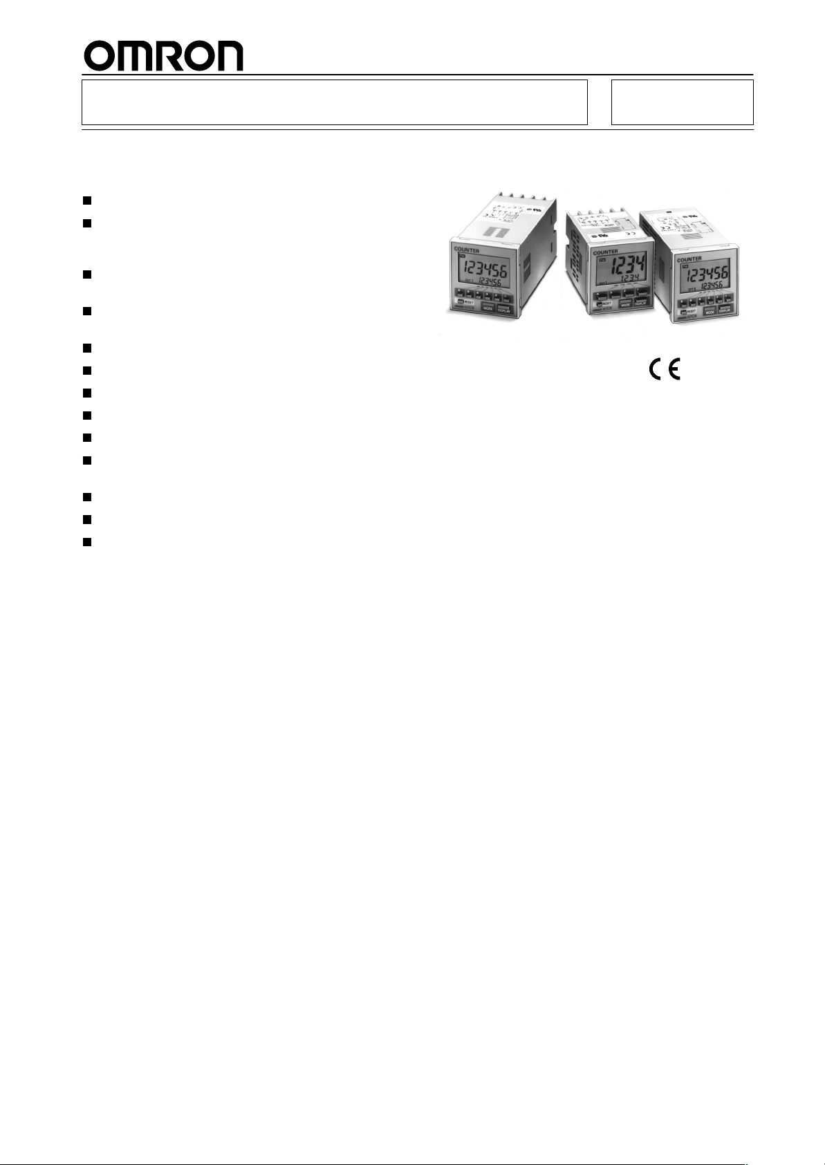
Digital Counter H7CR
DIN 48 x 48 mm Counters with
Easy-to-use Functions
Designed with an emphasis on ease of operation.
All models (except -A, and -SA type) equipped with
prescale function which displays in units of actual
physical parameters (length, volume, etc.).
H7CR-C/SC large/small discrimination mode useful for positioning and production control.
High-speed response allows 5,000 counts per
second.
High-visibility LCD display with built-in backlight.
Online change of set value possible.
Meets UL and CSA standards.
Conforms to EN61010-1 standard.
H7CR-S short type only 64 mm deep.
H7CR-8/11 plug-in types can be DIN-track
mounted.
H7CR-8 has a built-in power supply reset function.
Conforms to EMC standards.
Six-language instruction manual provided.
RC
1
Page 2

H7CR
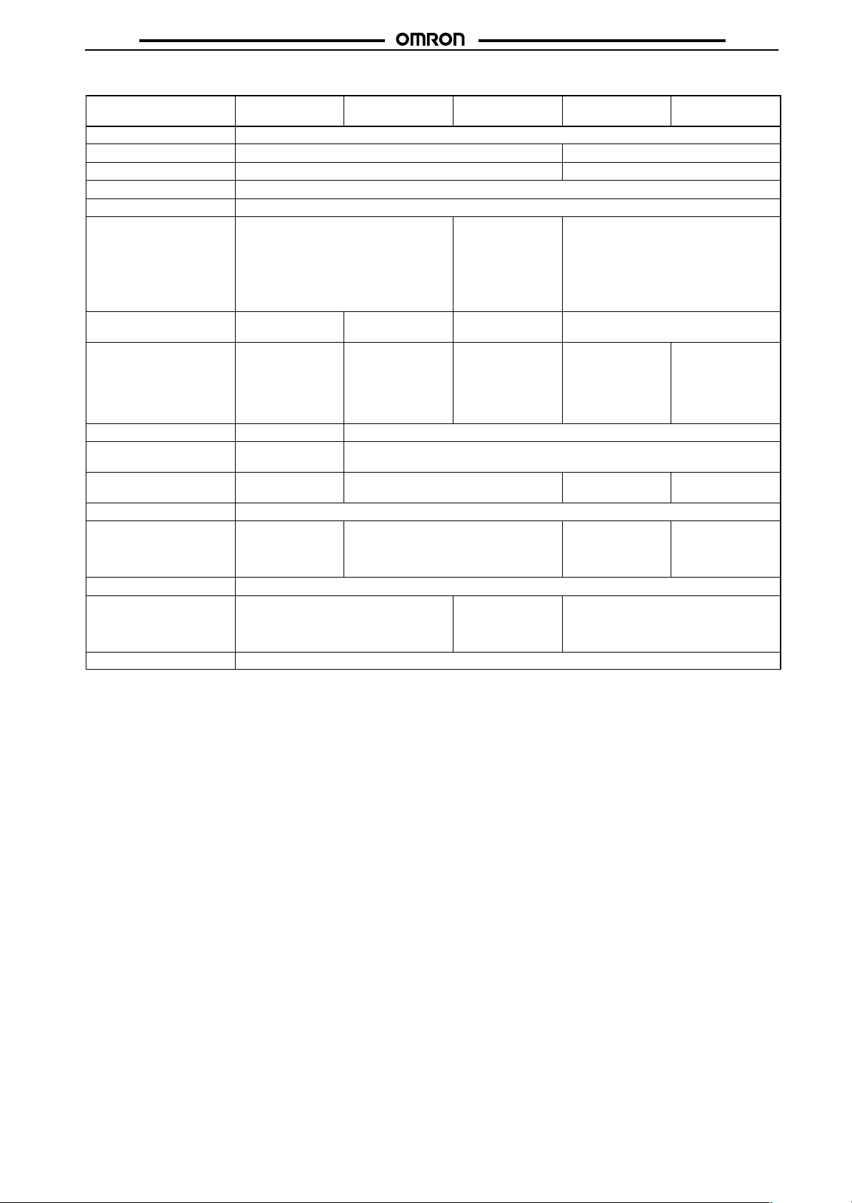
Ordering Information
H7CR-A/B/C
H7CR
H7CR Counters
External
power supply
Unused
12 VDC
(100 mA)
24 VDC
(50 mA)
Outputs
Contact
Transistor
Contact
Transistor
Contact
Transistor
Control
supply
voltage
100 to 120/
200 to 240 VAC
50/60 Hz
24 VAC
100 to 120/
200 to 240 VAC
50/60 Hz
24 VAC
100 to 240 VAC
50/60 Hz
24 VAC
12 to 24 VDC
100 to 240 VAC
50/60 Hz
24 VAC
12 to 24 VDC
100 to 240 VAC
50/60 Hz
24 VAC
12 to 24 VDC
100 to 240 VAC
50/60 Hz
24 VAC
12 to 24 VDC
Basic type
(without backlight)
Standard
(with backlight)
±Range type
(with backlight)
One Stage One Stage Two Stages One Stage Two Stages
No-voltage
Input
Voltage
input
No-voltage
Input
Voltage
input
No-voltage
Input
Voltage
input
No-voltage
Input
Voltage
input
Digits
6
digits4digits6digits4digits6digits4digits6digits4digits6digits4digits6digits4digits
H7CR
-A
H7CR
-A
H7CR
-AS
H7CR
-AS
H7CR
-A4
H7CR
-A4
H7CR
-A4S
---
---
H7CR
-AV
---
H7CR
-AV
---
H7CR
-AVS
---
H7CR
-AVS
---
---
--- --- --- ---
--- ------
H7CR
H7CR
-B4
-B
---
H7CR
-B
H7CR
H7CR
-B4S
-BS
---
H7CR
-BS
H7CR
H7CR
-BG
-B4G
H7CR
---
-BG
H7CR-
H7CR
B4SG
-BSG
---
H7CR
-BSG
H7CR
-BV
H7CR
-BW
H7CR
-BVS
H7CRBVS
H7CR
-BVG
H7CR
-BVG
H7CRBVSG
H7CRBVSG
H7CR
-B4V
H7CR
-B4W
H7CRB4VS
H7CR
-BVS
H7CRB4VG
H7CRB4VG
H7CRB4VSG
H7CRBVSG
H7CR
-BW
H7CR
-BW
H7CR
-BWS
H7CR
-BWS
H7CR
-BWG
H7CR
-BWG
H7CRBWSG
H7CRBWSG
--- --- ---
H7CR
H7CR
-BW
-BWV
H7CR
H7CR
-BW
-BWV
H7CR
H7CR-
-BWS
BWVS
H7CR-
H7CR
BWVS
-BWS
H7CR
H7CR-
-BWG
BWVG
H7CR
H7CR-
-BWG
BWVG
H7CR-
H7CR-
BWSG
BWVSG
H7CR-
H7CR-
BWSG
BWVSG
H7CR
-BWV
H7CR
-BWV
H7CRBWVS
H7CRBWVS
H7CRBWVG
H7CRBWVG
H7CRBWVSG
H7CRBWVSG
6
digits4digits6digits4digits
H7CR-C
H7CR
-CV
H7CR-C
H7CR
-CV
H7CR-CS
H7CRCVS
H7CR-CS
H7CR
-CVS
H7CR
H7CR-CG
-CVG
H7CR
H7CR-CG
-CVG
H7CR
H7CR-
-CVSG
CSG
H7CR
H7CR
-CVSG
-CSG
No-voltage
Input
H7CR
-CW
H7CR
-CW
H7CR
-CWS
H7CR
-CWS
H7CR
-CWG
H7CR
-CWG
H7CR
-CWSG
H7CR
-CWSG
Voltage
input
H7CR
-CWV
H7CR
-CWV
H7CR
-CWVS
H7CR
-CWVS
H7CR
-CWVG
H7CR
-CWVG
H7CR
-CWVSG
H7CR
-CWVSG
2
Page 3

H7CR
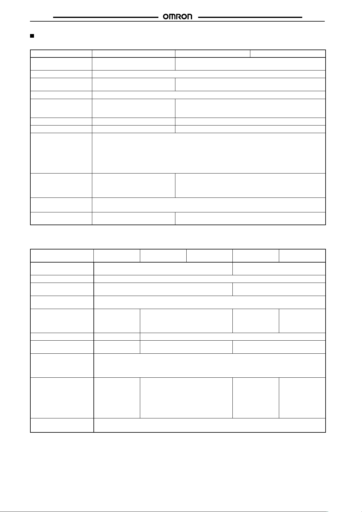
H7CR-S (Short Body)
H7CR
H7CR-S
H7CR-8/11 (Plug-in Socket)
External
power
supply
Unused
Outputs
Contact
Transistor
Control
supply
voltage
12 to 24 VDC
Basic type
(with backlight)
One
Stage
H7CR
-SA4L
H7CR
-SA4SL
No-voltage
H7CR
-SBL
H7CR
-SBSL
No-voltage
Input
6
digits4digits6digits4digits6digits4digits
H7CR
-SAL
H7CR
-SASL
Standard
(with backlight)
One
Stage
Input
H7CR
-SB4L
H7CR
-SB4SL
H7CR-8/11
Standard
(with backlight)
One Stage
No-voltage
Digits
---
H7CR
-SBWSL
Two
Stage
Input
---
H7CR
-SB4WSL
±Range type
(with backlight)
One
Stage
No-voltage
Input
6
digits
H7CR
-SCL
H7CR
-SCSL
Two
Stage
No-voltage
Input
4
digits
---
H7CR
-SCWSL
External
power
supply
Unused
Outputs
Contact
Transistor
Control
power
source
100 to 240 VAC
50/60 Hz
24 VAC
12 to 24 VDC
100 to 240 VAC
50/60 Hz
24 VAC
12 to 24 VDC
Note: Specify both the model and control supply voltage when ordering.
With shock prevention cover types are named ‘‘H7CR-jjjj-500.”
Power Supply
Reset Type (-8)
6
digits
H7CR-8
H7CR-8
H7CR-8S
H7CR-8S
4
digits
H7CR-84
---
---
---
Digits
H7CR-11
H7CR-11
H7CR-11S
H7CR-11S
Memory Backup
Type (-11)
6
digits
H7CR-114
H7CR-114
4
digits
3
Page 4
H7CR
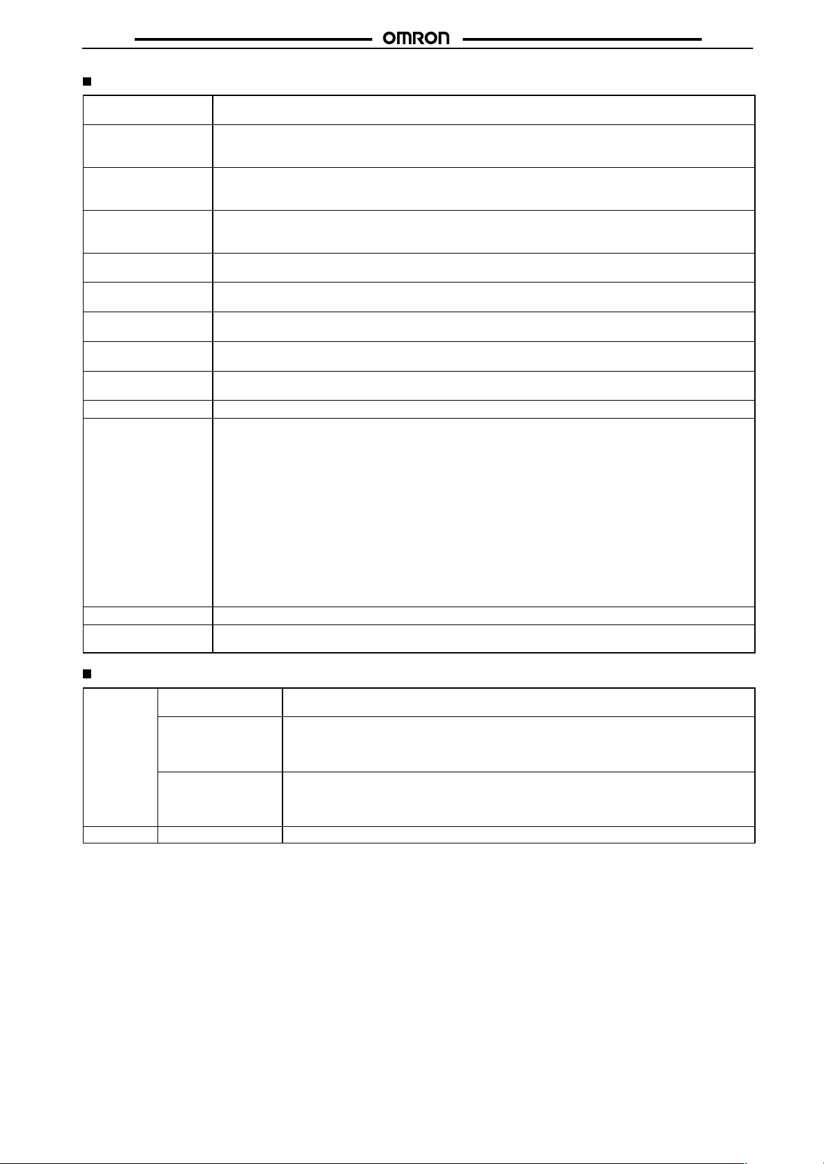
Model Number Legend
This model legend does not mean that all combinations of the following features are available.
H7CR-
8. Backlight
7. External Power Supply
(Only for -B or -C type)
6. Control Output
5. Input
4. Setting
3. No. of digits
2. Type
1. Depth
H7CR
1. Depth
S: Short
---: Not short
2. Type
A: Basic type
B: Standard type
C: ± Range type (Only for 6-digit display models)
8: Plug-in power reset
11: Plug-in power failure backup
3. No. of digits
4: 4
---: 6
4. Setting
W: 2-stage setting (Only for -B or -C type)
---: 1-stage setting
Accessories (Order Separately)
Name Model
Soft Cover (with two mounting clips) Y92A-48F1
Shock Prevention Cover Y92A-48T
Panel Mounting Bracket Y92F-30
Surface Mounting Bracket P2CF-08
Flush Mounting Bracket P3G-08
5. Input
V: Voltage input (Not for short body or plug-in type models)
---: No-voltage input
6. Control Output
S: Transistor output
---: Contact output
7. External Power Supply
(Only for -B or -C type)
G: 24-VDC power supply
---: Other than 24-VDC power supply
8. Backlight
L: Short body with backlight
---: Other than short body with backlight
Operating Environment
The counter has a water-resistive structure, thus preventing the internal circuitry from drops of water that may penetrate through the
space between the keys and operating panel. Before operating with
wet or oily hands, however, put a soft cover (sold separately) onto
the operating panel. Although the soft cover protects the instrument
to IPS4, avoid places where the counter is directly exposed to water
or oil.
A Y92F-30 Panel Mounting Adaptor is supplied with each counter.
(It can also be ordered independently.)
4
Page 5
H7CR
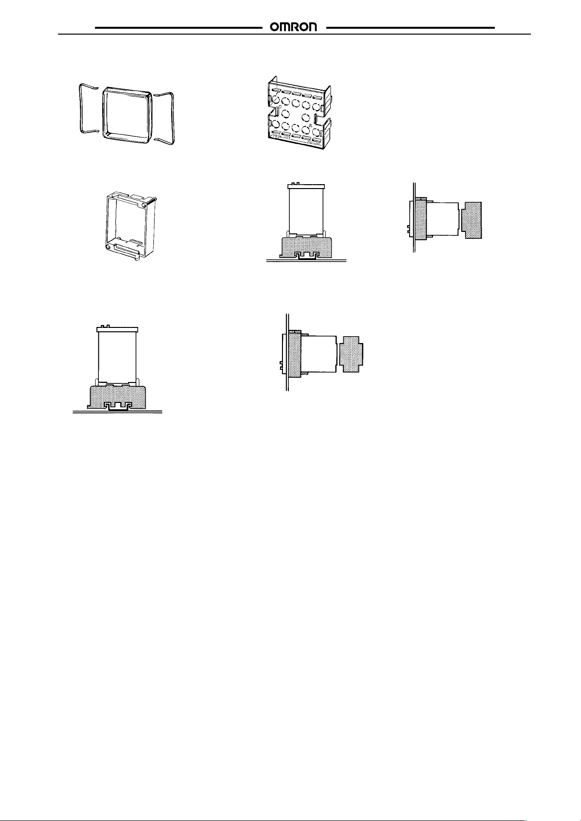
Soft Cover/Y92A-48F1 Shock Prevention Cover/Y92A-48T
Conforms to VDE 106/P100
H7CR
Panel Mounting Bracket/Y92F-30 Surface Mounting Bracket/
P2CF-08
H7CR-8
P2CF-08
Surface Mounting Bracket/
P2F-11
H7CR-11
P2CF-11
Note: Models with a Shock Prevention Cover can be ordered by adding “-500” to the end of the model number.
Example: H7CR-BW-500 (100 to 240 VAC, 50/60 Hz) (except plug-in type, H7CR-8/11)
Flush Mounting Bracket/
P3GA-11
Y92F-30
H7CR-11
P3GA-11
Flush Mounting Bracket/
P3G-08
Y92F-30
H7CR-8
P3G-08
5
Page 6
H7CR
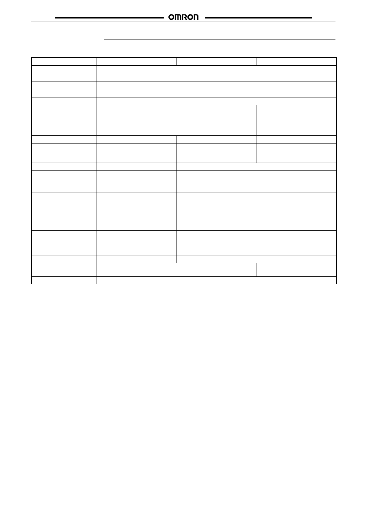
Specifications
H7CR-A/B/C
Model H7CR-A/A4 (Basic type) H7CR-B/B4 (Standard type) H7CR-C (±Range type)
Classification Digital preset counter
Mounting method Flush mounting
External connections Screw terminals
Enclosure ratings IP54 (panel surface)
Approved standards UL508, CSA C22.2 No.14, conforms to EN61010-1
Input modes* Up (incrementing), Down (decrementing), and reversible (Up/Down)
Output modes* N, F N, F, C, R, K, P, Q, A K, D, L, H
Reset system External and manual resets External, manual and automatic
Prescaling function --- Yes (0.001 to 99.999)
Decimal point
adjustment
Sensor power supply --- 12 VDC or 24 VDC (according to model)
Input signals Count and reset Count, reset, and key protection
Input method No-voltage input: Via opening
Control outputs SPST-NO contact or transistor
Display LCD LCD with backlight
Digits 6 digits (0 to 999,999), 4 digits (0 to 9,999) 5 digits negative and 6 digits
Memory backup
*Refer to timing charts for input and output mode operation.
Up/Down A (command inputs),
Up/Down B (individual inputs),
Up/Down C (phase difference inputs)
resets (internal according to C, R,
P, and Q mode operation)
--- Yes (Rightmost 3 digits)
and closing of contact
Voltage input: Via high and
low signal voltages (excluding
H7CR-A4 model)
(NPN open collector) output
Backup time for power interruption: Approx. 10 years at 20_C
No-voltage input: Via opening and closing of contact
Voltage input: Via high and low signal voltages (key protection
is no-voltage input only)
1 stage model: SPST-NO contact or transistor (NPN open
collector) output
2 stage model: 2 stages of SPST-NO contact or transistor (NPN
open collector) output
Reversible
Up/Down A (command inputs),
Up/Down B (individual inputs),
Up/Down C (phase difference
inputs)
External and manual resets
positive (–99,999 to 999,999)
H7CR
6
Page 7
H7CR
H7CR-S/8/11
Model H7CR-SA/SA4
(Basic type)
Classification Digital preset counter
Mounting method Flush mounting Flush mounting, surface mounting
External connections Screw terminals Socket
Enclosure ratings IP54 (panel surface)
Approved standards UL508, CSA C22.2 No.14, conforms to EN61010-1/IEC61010-1, EN50081-2 and EN50082-2
Input modes* Up (incrementing), Down
(decrementing), and reversible
(Up/Down)
Up/Down A (command inputs),
Up/Down B (individual inputs),
Up/Down C (phase difference inputs)
Output modes* N, F N, F, C, R, K, P, Q,AK, D, L, H N, F, C, R, K, P, Q, A
H7CR-SB/SB4
(Standard type)
H7CR-SC
(±Range type)
Reversible
Up/Down A
(command inputs),
Up/Down B
(individual inputs),
Up/Down C (phase
difference inputs)
H7CR-8/84
(Standard type)
Incrementing, decrementing, and
reversible (Up/Down)
Up/Down A (command inputs),
Up/Down B (individual inputs),
Up/Down C (phase difference inputs)
H7CR-11/114
(Standard type)
H7CR
Reset system External and
Prescaling function --- Yes (0.001 to 99.999)
Decimal point
adjustment
Input signals Count and reset Count, reset, and key protection Count and reset Count, reset, and
Input method No-voltage input: Via opening and closing of contact
Control outputs SPST-NO contact
Display LCD with backlight
Digits 6 digits (0 to 999,999)
Memory backup
Note: Only set values are backed up with H7CR-8j models.
manual resets
--- Yes (Rightmost 3 digits)
or transistor (NPN
open collector)
output
4 digits (0 to 9,999)
Backup time for power interruption: Approx. 10 years at 20_C (See note.)
External, manual,
automatic resets
(internal according
to C, R, P, and Q
mode operation)
1 stage model: SPST-NO contact or
transistor (NPN open collector) output
2 stage model: DPST-NO contact or
transistor (NPN open collector) output
External and
manual resets
5 digits negative
and 6 digits
positive (–99,999
to 999,999)
External, manual,
power supply, and
automatic resets
(internal according
to C, R, P, and Q
mode operation)
SPST-NO contact
or transistor (NPN
open collector)
output
6 digits (0 to 999,999)
4 digits (0 to 9,999)
External, manual,
automatic resets
(internal according
to C, R, P, and Q
mode operation)
key protection
SPDT-NO contact
or transistor (NPN
open collector)
output
7
Page 8
H7CR
H7CR
Ratings
H7CR-A/B/C
Model H7CR-A/A4 (Basic type) H7CR-B/B4 (Standard type) H7CR-C/C4 (±Range type)
Rated supply voltage 100 to 120 VAC/200 to 240 VAC,
Operating voltage range 85% to 110% of rated voltage
Current consumption Approx. 6.0 VA (at 50 Hz, 240 VAC);
Max. counting speeds 30/1k/5kcps (same setting for CP1 and CP2)
Reset Min. pulse width for external reset:
Key protection --- Response time: 1 s
One-shot time --- 10, 50, 100, 200, and 500 ms (separate setting for stages 1 and 2)
Count, reset inputs No-voltage input
Key protection input --- No-voltage input
Control outputs
External power supply --- 100 mA, 12 VDC ±10% (5% ripple max.)
*When power is turned ON, approx. 2 A (24 VAC) inrush current flows for about 2 ms.
**When power is turned ON, approx. 5 A (240 VAC), 8 A (24 VDC, 24 VAC) inrush current flows for about 2 ms.
50/60 Hz, 24 VAC
approx. 1.3 VA (at 25 VAC) *
20 ms,
manual reset
ON impedance: 1 kΩ max. (Approx. 2 mA when 0 Ω)
ON residual voltage: 2 V max.
OFF impedance: 100 kΩ max.
Voltage input (input resistance: approx. 4.7 kΩ)
High level: 4.5 to 30 VDC
Low level: 0 to 2 VDC
Contacts: 3 A at 250 VAC, resistance load (cos φ = 1), 3 A at 30 VDC, resistance load (cos φ = 1)
Transistor output: Open collector 100mA at 30 VDC max. residual voltage 2 V max. (Approx. 1 V)
H7CR-S/8/11
Model H7CR-SA/SA4
Rated supply voltage 12 to 24 VDC (contains 20% ripple max.) 100 to 240 VAC, 50/60 Hz, 24 VAC/12 to
Operating voltage range 85% to 110% of rated voltage
Current consumption Approx. 1.3 W (at 24 VDC) * Approx. 2.8 VA (at 50 Hz, 240 VAC) *
Max. counting speeds
(CP1, CP2 count input)
Reset Min. pulse width
Key protection --- Response time: approx. 1 s
One-shot time --- 10, 50, 100, 200, and 500 ms (separate
Count, reset inputs No-voltage input
Key protection input --- No-voltage input
Control outputs
*When power is turned ON, approx. 5 A (24 VDC, 240 VAC) inrush current flows for about 2 ms.
**When power is turned ON, approx. 8 A (24 VDC, 24 VAC) inrush current flows for about 2 ms.
(Basic type)
30/1k/5kcps (same setting for CP1 and CP2)
for external reset:
20 ms
manual reset
ON impedance: 1 kΩ max. (Approx. 2 mA when 0 Ω)
ON residual voltage: 2 V max.
OFF impedance: 100 kΩ max.
Contacts: 3 A at 250 VAC, resistance load (cos φ= 1)
Transistor output: Open collector 100mA at 30 VDC max. residual voltage 2 V max. (Approx. 1 V)
H7CR-SB/SB4
(Standard type)
Min. pulse width for external reset: 1 or
20 ms
manual reset
setting for stages 1 and 2)
ON impedance: 1 kΩ max.
ON residual voltage: 1 V max.
OFF impedance: 100 kΩ min.
100 to 240 VAC, 50/60 Hz, 24 VAC/12 to 24 VDC (ripple: 20%
max.)
Approx. 6.6 VA (at 50 Hz, 240 VAC); approx. 3.2 W (at 24 VDC)**
Min. pulse width for external reset: 1 or 20 ms,
manual reset
ON impedance: 1 kΩ max. (Approx. 2 mA when 0 Ω)
ON residual voltage: 1 V max.
OFF impedance: 100 kΩ min.
50 mA, 24 VDC ±10% (5% ripple max.)
H7CR-SC
(±Range type)
(Approx. 2 mA when 0 Ω)
H7CR-8/84
(Standard type)
24 VDC (ripple: 20% max.)
approx. 1.3 W (at 24 VDC) **
Min. pulse width for
external reset: 1 or 20
ms, manual reset,
power reset: 0.5 s
10, 50, 100, 200, and 500 ms
---
(Standard type)
Min. pulse width
for external reset:
1 or 20 ms
manual reset
No-voltage input
ON impedance: 1 kΩ
max. (Approx. 2 mA
when 0 Ω)
ON residual voltage:
1 V max.
OFF impedance:
100 kΩ min.
H7CR-11/114
8
Page 9
H7CR
H7CR
Characteristics
Insulation resistance 100 MΩ min. (at 500 VDC) (between current-carrying terminal and exposed non-current-carrying metal parts,
Dielectric strength 2,000 VAC, 50/60 Hz for 1 min (between current-carrying terminal and exposed non-current-carrying metal
Impulse withstand
voltage
Noise immunity ±2 kV (between power terminals) and ±600 V (between input terminals), square-wave noise by noise
Static immunity Destruction: 15 kV
Vibration resistance Destruction: 10 to 55 Hz with 0.75-mm single amplitude for 4 cycles each in 3 directions (8 min per cycle)
Shock resistance Destruction: 300 m/s
Life expectancy Mechanical: 10 million operations min.
Ambient temperature Operating: –10°C to 55°C (with no icing)
Ambient humidity Operating: 35% to 85%
EMC (EMI) EN61326
Case color Light gray (Munsell 5Y7/1)
Weight H7CR-A/A4 (AC type): approx. 230 g; H7CR-B/B4/C: approx. 170 g
and between non-continuous contacts)
parts) for 100 to 240 VAC type
1,000 VAC for 24VAC/12 to 24 VDC type and for transistor output type
3 kV (between power terminals) for 100 to 240 VAC type, 1 kV for 24 VAC/12 to 24 VDC
4.5 kV (between current-carrying terminal and exposed non-current-carrying metal parts for 100 to 240 VAC
type, 1.5 kV for 24 VAC/12 to 24 VDC.
simulator (pulse width: 100 ns/1 µs, 1-ns rise)
±480 V (between power terminals) for H7CR-S type
Malfunction: 8 kV
Malfunction: 10 to 55 Hz with 0.5-mm single amplitude for 4 cycles each in 3 directions (8 min per cycle)
2
each in three directions.
Malfunction: 100 m/s
Electrical: 100,000 operations min. 5A at 250 VAC in load resistance
Storage: –25°C to 65°C (with no icing)
Emission Enclosure: EN55011 Group 1 class A
Emission AC mains: EN55011 Group 1 class A
(EMS) EN61326
Immunity ESD: EN61000-4-2: 4 kV contact discharge (level 2)
Immunity RF-interference: EN61000-4-3: 10 V/m (Amplitude-modulated, 80 MHz to 1 GHz) (level 3);
Immunity Conducted
Disturbance: EN61000-4-6: 10 V (0.15 to 80 MHz) (according to EN61000-6-2)
Immunity Burst: EN61000-4-4: 2 kV power-line (level 3);
Immunity Surge: EN61000-4-5: 1 kV line to lines (power and output lines) (level 2);
Immunity Voltage Dip/Interruption EN61000-4-11: 0.5 cycle, 100% (rated voltage)
H7CR-S/S4: approx. 120 g; H7CR-8/84/11/114: approx. 150 g
2
each in three directions.
8 kV air discharge (level 3)
10 V/m (Pulse-modulated, 900 MHz ±5 MHz) (level 3)
2 kV I/O signal-line
2 kV line to ground (power and output lines) (level 3)
I/O Functions
Inputs CP1/CP2 Count signal inputs.
Reset Resets present value. (to zero in Up modes, to preset with 1-stage models in Down mode, and
Key protection
(See note.)
Outputs OUT 1.2 Outputs made according to designated output mode when corresponding preset is reached.
Note: Not set for the Basic type and H7CR-8.
Up, Down, and Up/Down (command, individual, or phase difference) inputs accepted.
to preset with 2-stage models.)
Count inputs are not accepted while reset input is ON.
Reset indicator lit while reset input is ON.
Makes keys inoperative according to key protection level.
Key protection indicator lit while key protection input is ON.
Effective when power supply is turned off.
Effective when protect terminals are shorted.
9
Page 10

H7CR
Engineering Data
Life-test Curve (Reference Values)
Electrical Life Expectancy
(Resistive Load)
H7CR
Electrical Life Expectancy
(Inductive Load)
3
30 VDC (cos φ = 1)
No. of operations (x 10 )
250 VAC (cos φ = 1)
Load current (A)
Reference: A current of 0.15 A max. can be switched at 125 VDC (cos
cases, a life of 100,000 operations can be expected.
The minimum applicable load is 10 mA at 5 VDC (failure level: P, reference value).
Nomenclature
Indicator
1. Power indicator
2. Key protection indicator
3. Control output indicator
OUT: 1 stage
OUT1, OUT2: 2 stages
4. Present value
(character height: 8 mm)
(Zeroes suppressed)
5. Set value
(character height: 4 mm)
(Indicates data in function setting
mode)
6. Set value 1,2 stage indicator.
1
6
10
3
30 VDC (L/R = 7 ms)
No. of operations (x 10 )
250 VAC (cos φ = 0.4)
Load current (A)
φ =1) and a current of 0.1 A max. can be switched if L/R = 7 ms. In both
Operation Key
2
3
7. Increment Keys (1 to 6)
(Used to change the
corresponding digit of the set
value. Increment Key (6) of
H7CR-C/SC also can be
switching for ±code. Used to
4
5
change data in the
function setting mode.)
8. Display Key
(Switches to the setting displays.
7
For 2 stage model, switch set value
1,2.)
9. Mode Key
(Switches from run mode to
function setting mode. Changes
items in the function setting mode.
89
10.Reset Key
(Resets present value and
outputs.)
Indicator
1. Power indicator
2. Key protection indicator
3. Control output indicator
OUT: 1 stage
OUT1, OUT2: 2 stages
4. Present value
(character height: 12 mm)
(Leading zeros suppressed)
5. Set value
(character height: 4.5 mm)
(Indicates value in function Setting
Mode)
6. Set value stage 1 and 2 indicators.
10
Operation Key
7. Increment Keys (1 to 4)
(Used to change the corresponding
digit of the set value. Used to
1
2
3
6
10
98
4
5
7
change data in the function Setting
Mode.)
8. Display Key
(Switches to the setting displays.
For 2-stage models, switches set
value 1 and 2.)
9. Mode Key
(Switches from Run Mode to Setting
Mode. Changes items in the Setting
Mode.
10. Reset Key
(Resets present value and outputs.)
Page 11

H7CR
H7CR
Operation
Factory Settings
The following table shows the timer settings when it is shipped. Please change the settings as necessary to suit the system before operation.
Settings and the display receive power from the internal battery and are therefore unaffected by external power interruptions.
H7CR-A/B/C
Model H7CR-A/A4 (Basic type) H7CR-B/B4 (Standard type) H7CR-C (±Range type)
Present value 0 0 0
Presets 0 0 0
Input mode Up Up Up/Down C (phase difference)
Output mode N N K
Output 2 time (HOLD) (HOLD) 500 ms
Output 1 time --- HOLD 500 ms
Counting speeds 30 cps 30 cps 30 cps
Min. reset time (20 ms) 20 ms 20 ms
Decimal point (no fractions) Far right (no fractions) Far right (no fractions)
Prescale (1,000) 1,000 1,000
Key protection level --- KP-1 KP-1
Note: With the initial settings, there will be no output even if the power supply is connected. External inputs and outputs cannot be used
without a power supply .
H7CR-S/8/11
Model H7CR-SA/SA4
(Basic type)
Present value 0 0 0 0
Presets 0 0 0 0
Input mode Up Up Up/Down C (phase
Output mode N N K N
Output 2 time (HOLD) (HOLD) 500 ms (HOLD)
Output 1 time --- HOLD 500 ms --Counting speeds 30 cps 30 cps 30 cps 30 cps
Min. reset time (20 ms) 20 ms 20 ms 20 ms
Decimal point (no fractions) Far right (no fractions) Far right (no fractions) Far right (no fractions)
Prescale (1,000) 1,000 1,000 1,000
Key protection level --- KP-1 KP-1 KP-1 (H7CR-11 only)
Note: With the initial settings, there will be no output even if the power supply is connected. External inputs and outputs cannot be used
without a power supply .
H7CR-SB/SB4
(Standard type)
H7CR-SC
(±Range type)
difference)
H7CR-8/11/84/114
(Standard type)
Up
11
Page 12

H7CR
Operational Overview
Run mode
H7CR
Setting mode
Present value,
set value 1
Press the
DISPLAY Key
Present value,
set value 2
Press the
MODE Key
Press the
DISPLAY Key
Press the
MODE Key
Input mode
Output mode
Output 2 time
Output 1 time
Count speed
Min. reset time
Decimal point
Prescale value
Press the
MODE Key
Press the
MODE Key
Press the
MODE Key
Press the
MODE Key
Press the
MODE Key
Press the
MODE Key
Press the
MODE Key
Press the
MODE Key
Key protection level
Note: Set values are changed with the Increment
Keys (1 to 6 (4)).
Setting Item Table
Mode Setting Applicable model H7CR Description Setting procedure
Run
mode
Function
setting
mode
item -A/
Set value
1, 2
Input
mode
-B/
A4/
SA/
SA4
-C/SC-8
B4/
SB/
SB4
/84
-11/
114
No Yes Yes No No Compared to the present
value. Determines the
timing of the control
output according to the
output mode. The
DISPLAY Key switches
between set value 1 and
2. (2-stage model only.)
Yes Yes Yes Yes Yes Determines the input
mode selecting from Up,
Down, Up/Down modes.
Sequence when changing a digit using the
Increment Keys (1 to 6 (4)).
0891 (Ć)
.....
Note: (-) is H7CR-C and -SC type (Increment Key
6) only.
Press keys 1 to 6 (4) to change the displayed
mode.
u* d* udĆa udĆb udĆc
(Up) (Down) (Up/Down A) (Up/Down B) (Up/Down C)
*No input mode for -C/SC type.
12
Page 13

H7CR
Mode Setting Applicable model H7CR Description Setting procedure
Function
setting
mode
item -A/
Output
mode
Output
time 1
(2-stage
model
only)
Count
speed
Min. reset
time
Decimal
point
-B/
A4/
SA/
SA4
Yes Yes Yes Yes Yes Determines the form of
No Yes Yes No No Determines the output
Yes Yes Yes Yes Yes Switches the count input
No Yes Yes Yes Yes Determines the initial
No Yes Yes Yes Yes Determines the decimal
-C/SC-8
B4/
SB/
SB4
/84
-11/
114
the control output. (Refer
to the present value vs.
output diagrams on
pages 16 to 18.)
Determines the output
time for control output
(Output 2).
time of the control output
(OUT 1) for 2-stage
model counters.
filter to protect against
errant counts due to
interference.
signal width of the
external reset.
point position of the
present and set values.
Press keys 1 to 6 (4) to change the displayed
mode.
H7CR-A/SA
H7CR-B/SB/8/11
nf cR p Q aK
(N) (F) (C) (R) (K) (P) (Q) (A)
H7CR-C/SC
Kdl h*
(K) (D) (L) (H)
Press keys 1 to 6 (4) to change the Output 2
time. (Applicable to output modes C, R, K, P,
Q, and A only.
10
ms 50ms 100ms 200ms 500ms
Press keys 1 to 6 (4) to change the displayed
mode.
nf
(N) (F)
hold
10ms 50ms 100ms 200ms 500ms
*H7CR-BW/SBW only.
Press keys 1 to 6 (4) to change the displayed
mode.
30 1K sK
(30cps) (1kcps) (5kcps)
Press keys 1 to 6 (4) to change the displayed
mode.
Move the decimal point position from left to right
with keys, 1 to 6 (4).
(1 ms) (20 ms)
120
H7CR
*
2-stage model only.
*
Prescale
value
(See note
2.)
Key
protection
level
Note: 1. Settings changed in setting mode are not effective until run mode is entered.
2. Incorrectly setting the prescale value may result in counting errors. Check that the prescale value is set correctly before starting
operation.
No Yes Yes Yes Yes Can calculate and display
a physical parameter
(volume, length, etc.)
from the present value.
For example, if one count
input represented a
movement of 0.02 mm,
the prescale value would
be 0.02. Values from
0.001 to 99.999 are
possible.
No Yes Yes No Yes Locks certain keys to
prevent accidental
operation. The key
protection level, kP-1 to
kP-4, determines which
keys are locked when the
key protection input is
ON. The locked keys are
crossed out in the
diagram on the right.
Change the value of the digits with the
corresponding keys, 1 to 6 (4).
012 89
Sequence when changing the key protection
level using the Increment Keys (1 to 6 (4)).
.....
.
12345
KpĆ1 KpĆ2 KpĆ3 KpĆ4
<KP–1> <KP–2>
<KP-4><KP–3>
13
Page 14

H7CR
Examples
Run Mode
Changing the Set Value
1. Press the DISPLAY Key to change the displayed preset value 1
and 2 during operation.
Setting Mode
Changing Settings in the Function Setting Mode
1. Press the MODE Key to switch from run mode to setting mode.
• The Counter will continue operation if switched from run
mode to function setting mode during operation.
• The MODE Key will be locked if the key protection function is
enabled.
• Settings changed in the function setting mode are not
effective until run mode is entered. As the operating
conditions will change in this case, always reset operation
with the RESET Key or a reset input.
H7CR
2. Change the set value from 250 to 1,250.
• Pressing keys 1 through 6 (1 through 4 for 4-digit models)
increments the corresponding column by1.
• Non-significant zeros are normally not shown on the set value
display.
3. Changing the selected item
• Press the MODE Key until the desired item appears
• Change the item setting by pressing keys 1 through 6 (1
through 4 for 4-digit models). (Press the DISPLAY Key to
switch back from function setting mode to run mode.)
2. Press the MODE Key to scroll successively through the items
that can be set. Release the MODE Key to select the desired
item.
14
• Press the DISPLAY Key to return to Run mode from Setting
mode.
Page 15

H7CR
Input Modes and Count Value
Up (increment) mode Down (decrement) mode
Count
H
input
CP1
Gate
input
CP2
Count
Gate
input
CP1
Count
input
CP2
Count
L
A A
H
L
2
1
0
0
H
L
A A
H
L
1
0
0
Inhibit
3
Inhibit
2
H7CR
Count
H
input
CP1
Gate
input
CP2
5
4
Count
Gate
input
CP1
Count
input
CP2
5
4
3
Count
L
A A
H
L
n
n-1
n-2
0
H
L
A A
H
L
n
n-1
0
Inhibit
n-3
n-4
n-5
Inhibit
n-2
n-3
n-4
n-5
Up/Down A Command input mode Up/Down B Individual input mode
H
CP1
L
A
H
CP2
L
3
2
Count
Up/Down C Phase difference input mode (See note 2.)
H
L
H
L
Count
0
1
0
BB B B
3
2
1
2
2
A
1
1
H
CP1
L
H
CP2
L
3
2
Count
Note 1 A: Minimum signal width; B: Must be at least 1/2 of
Note 2 Set the same counting speed for CP1 and CP2 when
Note 3 H and L
3
2
1
0
minimum signal width. Signals may not be counted
if the minimums for A and B are not met.
in Up/Down C mode.
Signal No-voltage input Voltage input
H
L
Short circuit
Open circuit
3
2
2
11
4.5 to 30 VDC
0 to 2 VDC
3
2
15
Page 16

H7CR
Input/Output Mode Setting
H7CR-A/A4/B/B4/SA/SA4/SB/SB4/8/84/11/114 (N and R modes only apply to the -A and -SA types.)
Output 2 operation applies for 1-stage models only.
Output
mode Up Down Up/Down A.B.C
N
Reset
999999
Preset 2
Preset 1
0
Output 1
Output 2
Outputs and present value display are maintained until reset.
F
Reset
999999
Preset 2
Preset 1
0
Input mode
H7CR
Output 1
Output 2
Present value display runs continuously. Outputs are maintained until reset.
C
Reset
999999
Preset 2
Preset 1
0
Output 1
Output 2
Present value is placed in reset start status as soon as count up is reached. The count up is not displayed. Outputs are 1-shot and operate
repeatedly. Output 1 is self-holding, and goes off after expiration of the 1-shot period for Output 2. One-shot time periods for Output 1 and 2 are
independent.
R
Reset
999999
Preset 2
Preset 1
0
Output 1
16
Output 2
Present value is placed in reset start status as soon as count up is reached. Outputs are 1-shot and operate repeatedly. Output 1 is
self-holding, and goes off after expiration of the 1-shot period for Output 2. One-shot time periods for Output 1 and 2 are independent.
Page 17

H7CR
Output Input mode
mode Up Down Up/Down A.B.C
K
Reset
999999
Preset 2
Preset 1
0
Output 1
Output 2
Present value runs continuously. Output 1 is self-holding, and goes off after expiration of the 1-shot period for Output 2. One-shot time periods
for Output 1 and 2 are independent.
P
Reset
999999
Preset 2
Preset 1
0
H7CR
Output 1
Output 2
Present value display does not change during 1-shot time period, but reset start status is returned to as soon as count is reached. Outputs are
1-shot and operate repeatedly. Output 1 is self-holding, and goes off after expiration of the 1-shot period for Output 2. One-s hot time periods for
Output 1 and 2 are independent.
Q
Reset
999999
Preset 2
Preset 1
0
Output 1
Output 2
Present value runs continuously through 1-shot time period and returns to reset start status immediately afterward. Outputs are 1-shot and
operate repeatedly. Output 1 is self-holding, and goes off after expiration of the 1-shot period for Output 2. One-shot time periods for Output 1
and 2 are independent.
A
Reset
999999
Preset 2
Preset 1
0
Output 1
Output 2
Present value and output 1 maintain status until reset. Output 1 and 2 operate independently.
17
Page 18

H7CR
p
p
H7CR
One-shot output from Output 1
One-shot output from Output 2
Self-holding output Self-holding output
One-shot outputs can be set to between 10 and 500 ms.
Note: When the count value exceeds 999999, the display returns to 0, and when it is smaller than 0, the display changes to
999999.
H7CR-C/SC
Output 2 operation applies for 1-stage models only.
Output
mode
K
D
Input mode
Up/Down A.B.C
Compensation
Reset
999999
Compensation value
Set 2
Set 1
0
-999999
Output 1
Output 2
Compensation
Reset
999999
Compensation value
Set 2
Set 1
0
-999999
Operation after count
Present value
increments and
decrements within
displayable range.
Outputs go ON for
one-shot.
Present value
increments and
decrements within
displayable range.
Outputs are ON during
the count is equal.
up
Output 1
Output 2
18
Page 19

H7CR
p
p
H7CR
Output
mode
L
H
Compensation
Reset
999999
Compensation value
Set 2
Set 1
-999999
Output 1
Output 2
Compensation
Reset
999999
Compensation value
Set 2
Set 1
-999999
Input mode
Up/Down A.B.C
Operation after count
up
Present value
increments and
decrements within
displayable range.
Output 1 is ON
whenever present value
is less than or equal to
Set 1; Output 2 is ON
whenever present value
is greater than or equal
0
to Set 2.
Present value
increments and
decrements within
displayable range.
Output 1 is ON
whenever present value
is greater than or equal
to Set 1; Output 2 is ON
whenever present value
is greater than or equal
0
to Set 2.
Output 1
Output 2
Edge input
Level input
One-shot output
Instantaneous (equals) output
One-shot outputs can be set to between 10 and 500 ms.
Self-holding output/level input
Note: 1. Counting inputs are not applied while the reset input is ON.
2. One-shot outputs, when ON, are turned OFF when the reset input goes ON.
3. One-shot outputs, when ON, are reset and the one-shot output is restarted if a preset designating the output is reached.
19
Page 20

H7CR
Dimensions
Note: All units are in millimeters unless otherwise indicated.
The dimensions are the same for both the 4-digit and 6-digit
models.
H7CR-A/B/C
48
H7CR
6
100
M3.5 terminal screw
(effective length: 6 mm)
Flash Mounting Adapter
Panel Cutouts
Panel cutouts are
as shown at right.
(according to DIN43700).
48
Panel
58
60 min.
48
60 min.
+0.6
45
–0
+0.6
45
–0
6
n side-by-side
mounting
A = (48n-2.5)
44.8 44.8
Y92F-30
Flush Mounting Adapter
100
A
+1
–0
44.8 44.8
H7CR-S (Short Body)
H7CR-8/11
20
Note 1. The mounting panel thickness should be 1 to 4 mm.
2. It is possible to mount Counters side by side, but one way only.
M3.5 terminal screw
(effective length: 6 mm)
44.8 44.8
44.8 44.8
Page 21

H7CR
Flash Mounting Adapter
H7CR-S
Y92F-30
Panel
Flush Mounting Adapter
H7CR
44.8 44.8
H7CR-8/11
Panel Cutouts
Panel cutouts are
as shown at right.
(according to DIN43700).
60 min.
H7CR-8/11 Mounting Styles
Y92F-30
Panel
Flush Mounting Adapter
P3G-08
(P3GA-11)
Flush Mounting
Bracket
60 min.
+0.6
45
–0
+0.6
45
–0
n side-by-side
mounting
A
+1
–0A = (48n-2.5)
Note 1. The mounting panel thickness should be 1 to 4 mm.
2. It is possible to mount Counters side by side, but only horizontally.
Surface Mounting
98.8
101.1
P2CF-08
H7CR-8
Flush Mounting
Y92F-30
H7CR-8
+
P3G-08
112
109.7
H7CR-11
Adaptor
6 6
95.1
P2CF-11
Flush MountingSurface Mounting
Y92F-30
P3GA-11
H7CR-11
+
Adaptor
100.2
21
Page 22

H7CR
Installation
Terminal Arrangement
Terminal arrangements for the 4-digit models are the same as those shown below.
H7CR-A (Basic type)
1 Stage Contact Output
H7CR-A
H7CR-AV
100 to 120 VAC
1 Stage
Transistor Output
H7CR-AS
H7CR-AVS
100 to 120 VAC
Reset input
0 V
678910
11
12345
Reset input
0 V
678910
11
12345
CP2 input
24 VAC
CP2 input
24 VAC
CP1 input
Unused
12
UnusedUnused
200 to 240 VAC
CP1 input
Unused
12
UnusedUnused
200 to 240 VAC
1 Stage Contact Output
H7CR-B(G)
H7CR-BV(G)
H7CR-C(G)
H7CR-CV(G)
12 or
24 VDC
1 Stage Transistor Output
H7CR-BS(G)
H7CR-BVS(G)
H7CR-CS(G)
H7CR-CVS(G)
12 or
24 VDC
H7CR-B (Standard type), H7CR-C (±Range type)
CP2 input
Reset input
0 V
678910
11
(+)
12345
(-)
Reset input
0 V
678910
11
(+)
12345
(-)
CP1 input
(–)
Sensor
power
supply
100 to 240 VAC/24 VAC
12 to 24 VDC
(+)
CP2 input
CP1 input
(–)
Sensor
power
supply
100 to 240 VAC/24 VAC
12 to 24 VDC
(+)
Key protection
Unused
12
Unused
Key protection
Unused
12
Unused
2 Stage Contact Output
H7CR-BW(G)
H7CR-BWV(G)
H7CR-CW(G)
H7CR-CWV(G)
12 or
24 VDC
2 Stage Transistor Output
H7CR-BWS(G)
H7CR-BWVS(G)
H7CR-CWS(G)
H7CR-CWVS(G)
12 or
24 VDC
Reset input
0 V
678910
11
12345
(-)
Reset input
0 V
678910
11
12345
(-)
CP2 input
(–)
Sensor
power
supply
(+)
OUT2
100 to 240 VAC/24 VAC
12 to 24 VDC
(+)
CP2 input
CP1 input
(–)
Sensor
power
supply
(+)
OUT2
100 to 240 VAC/24 VAC
12 to 24 VDC
(+)
H7CR
CP1 input
Key protection
12
OUT1
Unused
Key protection
12
OUT1
No-contact
input
22
H7CR-8 (Standard type) H7CR-11 (Standard type)
CP2 input
CP1 input
Reset input
Contact input
4 5
3
2
1
8
24/100 to 240
VAC
12 to 24 VDC
Internal circuit
Contact
No-contact
input
input
6
6
7
8
(-8S type)
No-contact
input
(+)(–)
Reset input
CP2 input
CP1 input
Key protection
Contact input
6
7
5
4
3
10
2
1
11
24/100 to 240
VAC
12 to 24 VDC
Internal circuit
Contact
No-contact
input
input
8
8
9
9
11
(-11S type)
(+)(–)
Page 23

H7CR
H7CR-SA (Basic type) H7CR-SB (Standard type), H7CR-SC (±Range type)
1 Stage Contact Output
H7CR-SAL
Reset input
11
(–) (+)
1 Stage
Transistor Output
H7CR-SASL
Reset input
CP2 input
CP1 input
0 V
Unused
678910
12
OUT
12345
12 to 24 VDC
CP2 input
CP1 input
0 V
Unused
678910
H7CR
1 Stage Contact Output
H7CR-SBL
H7CR-SCL
UnusedUnused
1 Stage Transistor Output
H7CR-SBSL
H7CR-SCSL
Reset input
0 V
678910
Unused
11
12345
(–) (+)
Reset input
0 V
678910
CP2 input
CP1 input
Key protection
12
OUT
Unused
12 to 24 VDC
CP2 input
CP1 input
Key protection
Unused
2 Stage Transistor Output
H7CR-SBWSL
H7CR-SCWSL
Reset input
0 V
678910
---
CP2 input
CP1 input
Key protection
11
OUT
12345
(–) (+)
Unused
12 to 24 VDC
UnusedUnused
12
11
12345
(–) (+)
OUT
Unused
12 to 24 VDC
12
Unused
Note: Do not connect unused terminals.
Connections
The inputs of the H7CR are no-voltage (short circuit or open) inputs
and voltage inputs. (Key protection only for no-voltage inputs)
No-voltage Inputs (With an External Power Supply)
Open Collector
Input
0 V
External power supply
Reset input
CP2 input
CP1 input
Voltage Output Contact
PLC
Input
0 V
External power supply
CP2 input
Reset input
CP1 input
Input
Unused
Input
0 V
Reset input
Unused
CP2 input
CP1 input
11
12345
(–) (+)
OUT1
OUT2
12 to 24 VDC
Note: The DC power
supply must be
30 VDC max.
12
High: transistor ON High: transistor ON High: contact ON
23
Page 24

H7CR
No-voltage Inputs (Without an External Power Supply)
H7CR
Open Collector
Input
0 V
CP2 input
Reset input
CP1 input
Voltage Output Contact
PLC
Input
0 V
CP2 input
CP1 input
Reset input
Input
Input
0 V
Reset input
High: transistor ON High: transistor ON High: contact ON
No-voltage Input Signal Levels
1. High level
Transistor ON
No-contact
input
Residual voltage: 2 V max.
Impedance when ON: 1 kΩ max.
2. Low level
Transistor OFF
Impedance when OFF: 100 kΩ max.
Contact
input
Use contacts which can adequately switch 2 mA at 5 V
CP2 input
CP1 input
Note: The DC power
supply must be
30 VDC max.
Voltage Inputs (With an External Power Supply)
NPN Transistor
Input
0 V
Input
External power supply
CP2 input
Reset input
CP1 input
High: transistor OFF High: transistor ON High: contact ON
PNP Transistor Contact
External power supply
Input
0 V
Reset input
CP2 input
CP1 input
Input
CP2 input
Reset input
Note: The DC power
supply must be
30 VDC max.
CP1 input
24
Page 25

H7CR
Voltage Inputs (Without an External Power Supply)
H7CR
NPN Transistor
Input
0 V
CP2 input
Reset input
CP1 input
PNP Transistor Contact
Input
0 V
CP2 input
Reset input
High: transistor OFF High: transistor ON High: contact ON
Voltage Input Signal Levels
1. High level 4.5 to 30 VDC
2. Low level 0 to 2 VDC
Connection Examples with OMRON Sensors
3-wire DC type (NPN) 3-wire DC type (PNP)
Photoelectric
sensor
E3S-jA/B
Output (black)
12 to 24 V (brown)
0 V (blue)
Input
CP1 input
Photoelectric
sensor
E3S-A/B
Input
0 V
CP2 input
Reset input
Output (black)
12 to 24 V (brown)
0 V (blue)
Note: The DC power
supply must be
30 VDC max.
CP1 input
(-)
678910
11
(+)
12345
*Models ending in -BV have reversed logic.
Photoelectric
sensor
Output (black)
12 to 24 V (brown)
E3S-A/B
0 V (blue)
Sensor
power
supply
12
H7CR-B/BV
Using the external power supply
678910
H7CR-AV
12345
1211
Proximity
sensor
E2E-XjE
Output (black)
12 to 24 V (brown)
0 V (blue)
(-)
678910
Sensor
power
11
(+)
supply
H7CR-BV
12345
678910
H7CR-AV
12345
12
1211
25
Page 26

H7CR
Rotary Encoder Wiring Example
Power supply
Rotary encoder
A phase
0 V
B phase
(-)
678910
H7CR
11
(+)
H7CR-C
12345
12
26
Page 27

H7CR
Precautions
Sensor Power Supply
• The capacity of the external power supply is 100 mA at
12 V/50 mA at 24 V. When using a 24 VAC/12 to 24 VDC power
supply, reduce the load with the power supply voltage, as shown
in the following diagram (DC power supplies only).
100
50
Load current (mA)
20
10
0
1510 20 25
Supply voltage (VDC)
Power Supplies
• When turning the power ON and OFF, input signal reception is
possible, unstable, or impossible as shown in the diagram below .
The unstable period will vary with power supply voltage, and the
load conditions on external power supplies.
Power
supply
Input impossible impossible
ON
OFF
0 to 50 ms
10 ms
Possible
Unstable
• A switching regulator is used in the internal circuits of counters
with 100-to-240-VAC or 12-to-24-VAC specifications, causing
an inrush current (approx. 1.5 A) to flow when power is turned on.
If the capacity of the power supply to the counter is insufficient,
the counter may not start operation. Be sure to provide adequate
capacity (recommended supply capacity; H7CR: 15 W min. and
H7CR-S: 5 W min.)
• Connect the power supply voltage through a relay or switch in
such a way that the voltage reaches a fixed value immediately.
Transistor Output
• The H7CR transistor output is insulated from the internal circuitry
by a photocoupler, so either NPN or PNP output is possible.
NPN output PNP output
1 2 3 4 5 1 2 3 4 5
Load
(–) ())
Load
power
supply
(–) ())
Load
power
supply
DIP Switch Setting Changes
Any changes in the DIP switch settings while power is being supplied is invalid. Restart the power supply .
12 VDC
24 VDC
0 to 0.9 s
Load
H7CR
Self-diagnostic Function
• The following displays will appear if an error occurs. The present
value and output enter the same status as after pressing the
RESET Key.
Display
ĆĆĆĆĆĆ*
ffffff**
e1
e2
*Displayed when the present value has fallen below the min. value
in the H7CR-C/SC (±range type).
**Displayed when the present value has exceeded the max. value in
the H7CR-C/SC (±range type).
Error Output
Present
value
below min.
Present
value
above max.
CPU OFF Press
Memory Set at the
status
No
change
Correction Function
setting
Press
RESET KeyNochange
or reset
input
RESET Key
factory
Operating Environment
• When using the Counter in an area with much electronic noise,
separate the Timer, wiring, and the equipment which generates
the input signals as far as possible from the noise sources. It is
also recommended to shield the input signal wiring to prevent
electronic interference.
• Organic solvents (such as paint thinner), as well as very acidic or
basic solutions might damage the outer casing of the Counter.
Using the Prescale Function
• When setting the prescale value, be sure that the set value
satisfies this equation: set value “max. value - prescale value’. (if
the prescale value is 1,250, 999.999 - 1,250 = 998.749 max.)
• If a higher value is used, the output may be affected, so make
sure that the output is produced before starting operation.
Changing Set Values
• When changin g t h e s e t v a l u e while the Counter is operating, the
output will be produced if the set value ever equals the present
value. To avoid triggering the output, begin by incrementing a
higher digit to a large number.
Resetting with a Set Value of 0
• When resetting is performed with the set value set to “0,” no
output will be given for the safety reasons once the reset is
turned OFF (except for the H7CR-C).
Output Delay
• The following table shows the delay from when the present value
passes the set value until the output is produced. (The delay is
the result of output control time, signal transmission time, relay
switching time, etc.)
Actual measurements in N and K modes.
Control output
Contact output 1, 2 30 cps 18 to 24 ms
Transistor output 1, 2 30 cps 13.5 to 20 ms
Max. counting
speed
1 kcps 4.7 to 5.8 ms
5 kcps 4.4 to 5.4 ms
1 kcps 0.59 to 0.81 ms
5 kcps 0.29 to 0.44ms
Output delay*
27
Page 28

H7CR
*The variation in delays is due to different modes and conditions.
For systems where the delay is a problem, take actual measurements under operating conditions.
Other
• When the Counter is installed in a control box and tests are
conducted which may damage the Counter’s internal circuitry
(for example, a test measuring the maximum voltage difference
between the control circuit and metal components), remove the
Counter from the control box or short circuit the terminals.
Caution
!
This product contains a lithium battery. Lithium batteries explode if incinerated. Dispose of the Digital Counter as a noncombustible item.
H7CR
ALL DIMENSIONS SHOWN ARE IN MILLIMETERS.
To convert millimeters into inches, multiply by 0.03937. To convert grams into ounces, multiply by 0.03527.
Cat. No.M012-E1-01D In the interest of product improvement, specifications are subject to change without notice.
OMRON Corporation
Industrial Automation Company
Industrial Control Components Division
Shiokoji Horikawa, Shimogyo-ku,
Kyoto, 600-8530 Japan
Tel: (81)75-344-7119/Fax: (81)75-344-7149
28
Printed in Japan
0802-1.5C (1190)
 Loading...