

Page 1
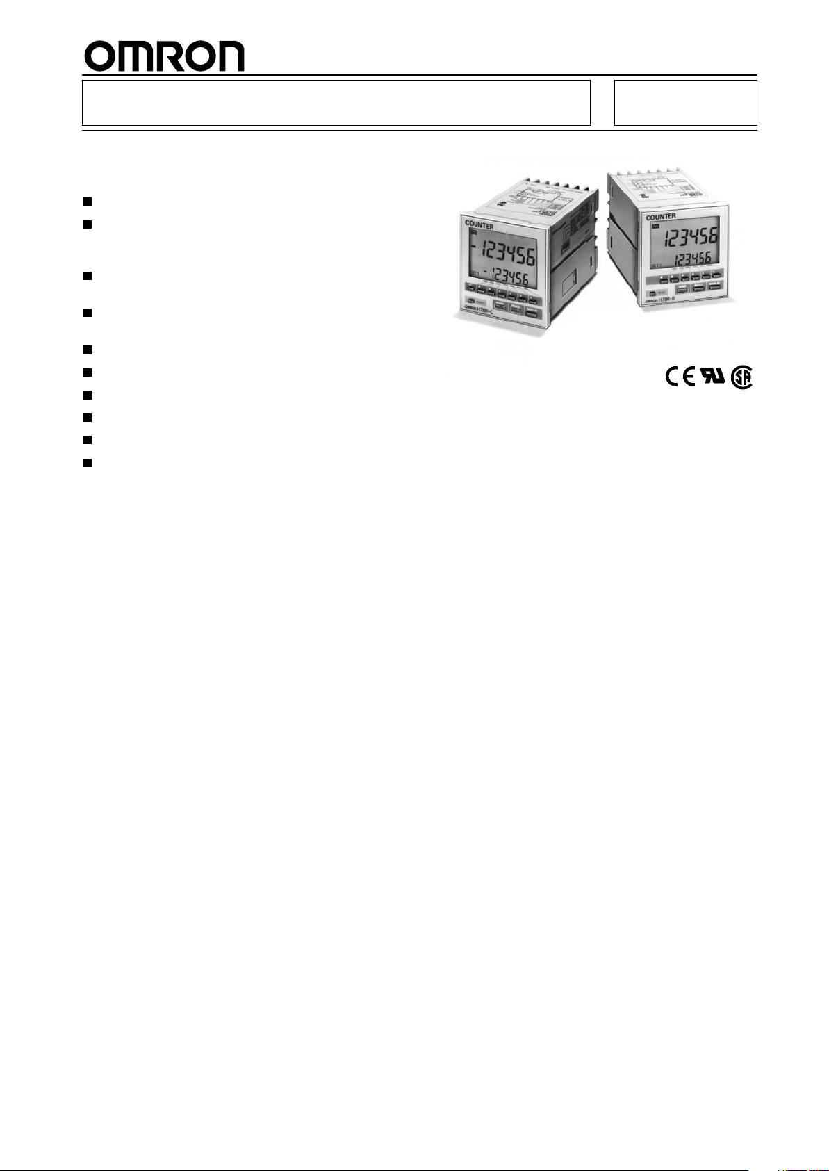
Digital Counter H7BR
DIN 72 x 72 mm Counters with
Easy-to-use Functions
Designed with an emphasis on ease of operation.
All models equipped with prescale function which
displays in units of actual physical parameters
(length, volume, etc.).
H7BR-C large/small discrimination mode useful for
positioning and production control.
High-speed response allows 10,000 counts per
second.
High-visibility LCD display with built-in backlight.
Online change of set value possible.
Meets UL and CSA standards.
Conforms to EMC standards.
Conforms to EN61010-1/IEC1010-1.
Six-language instruction manual provided.
1
Page 2
H7BR
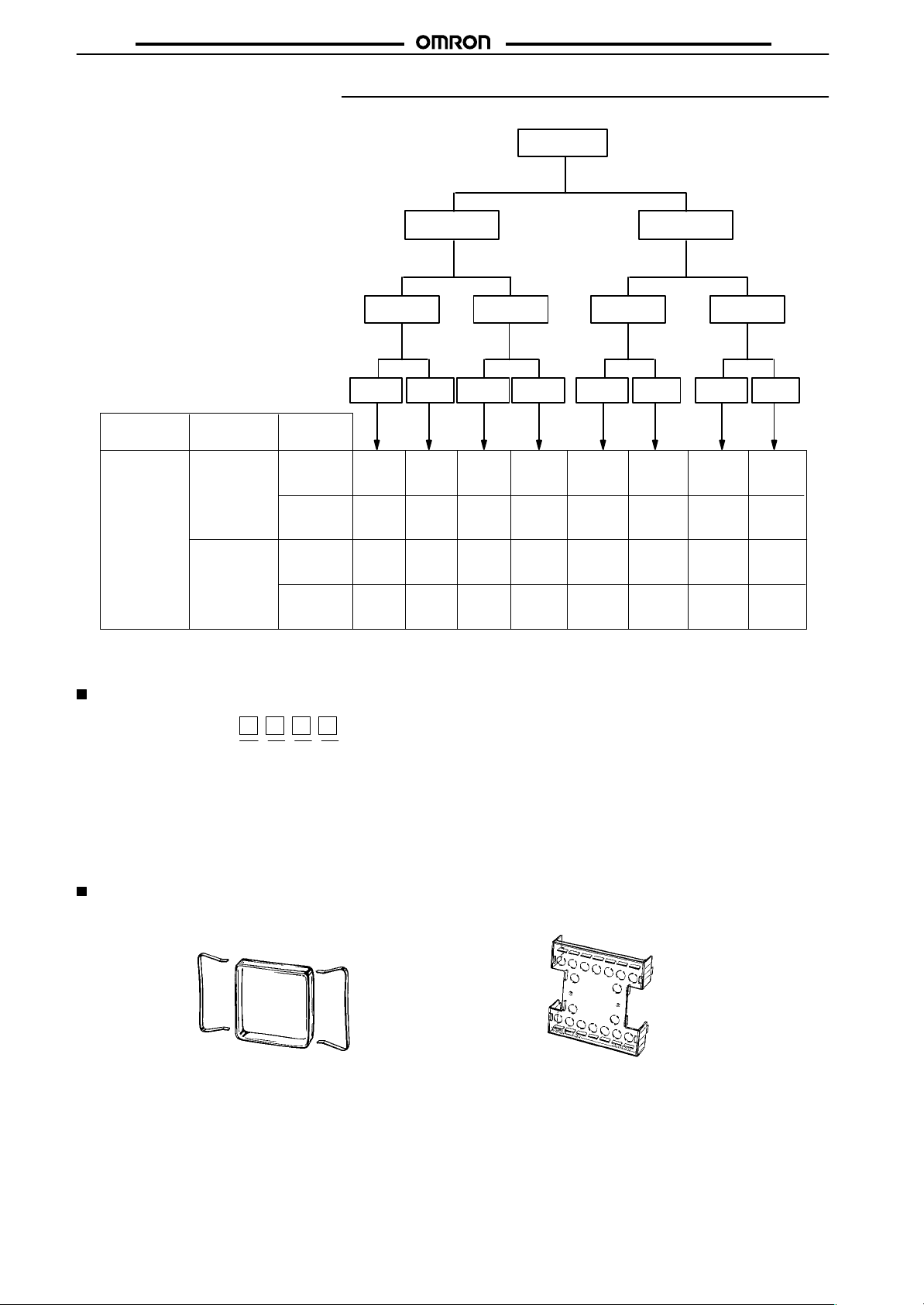
Ordering Information
H7BR
H7BR Counters
Standard
(with backlight)
One Stage Two Stages One Stage Two Stages
External
power supply
12/24 VDC
(switching)
[160 mA at 12 VDC;
80 mA at 24 VDC]
Outputs
Contact and NPN
transistor output
Contact and PNP
transistor output
Control
power
source
100 to 240 VAC
50/60 Hz
24 VAC
12 to 24 VDC
100 to 240 VAC
50/60 Hz
24 VAC
12 to 24 VDC
No-voltage
Input
H7BR-B
H7BR-B
H7BR-BP
H7BR-BP
H7BR-BV
H7BR-BV
H7BR-BVP
H7BR-BVP
Voltage
input
No-voltage
H7BR-BWP
H7BR-BWP
Note: Specify both the model and control power supply when ordering.
With shock prevention cover types are named “H7BR-jjjj-500.”
Model Legend
Input
H7BR-BW
H7BR-BW
Voltage
input
H7BR-BWV
H7BR-BWV
H7BR
-BWVP
H7BR
-BWVP
No-voltage
Input
H7BR-C
H7BR-C
H7BR-CP
H7BR-CP
±Range type
(with backlight)
Voltage
input
H7BR-CV
H7BR-CV
H7BR-CVP
H7BR-CVP
No-voltage
Input
H7BR-CW
H7BR-CW
H7BR-CWP
H7BR-CWP
Voltage
input
H7BR-CWV
H7BR-CWV
H7BR
-CWVP
H7BR
-CWVP
H7BR-
1234
1. Type
B: Standard
C: +/- range
2. Classification
None: 1-stage set counter
W: 2-stage set counter
3. Input Type
None: No-voltage input
V: Voltage input
4. Output Type
None: NPN output
P: PNP output
Accessories (Order Separately)
Soft Cover/Y92A-72F1
Hard Cover/Y92A-72
Note: Models with a Shock Prevention Cover can be ordered by adding “-500” to the end of the model number.
e.g., H7BR-B-500 (100 to 240 VAC, 50/60 Hz)
2
Shock Prevention Cover/Y92A-72T
Page 3
H7BR
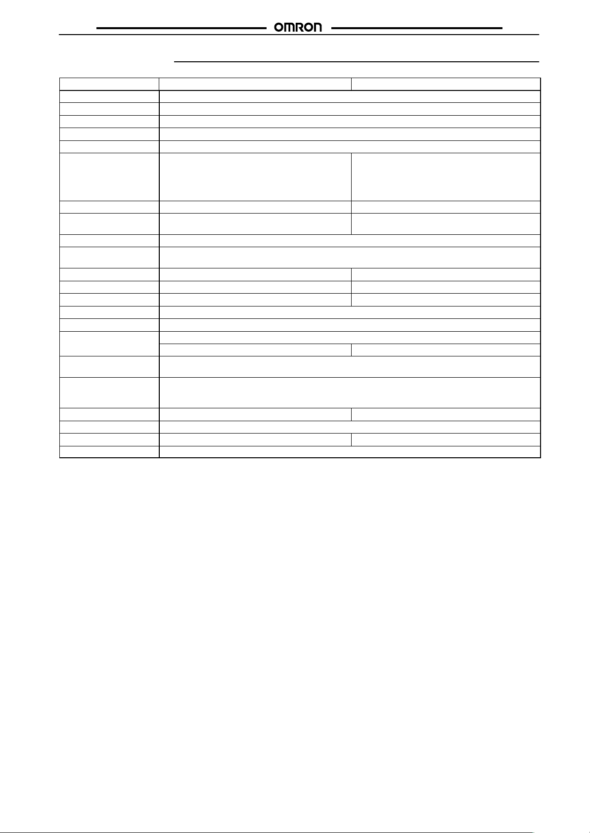
Specifications
Model H7BR-B (Standard type) H7BR-C (±Range type)
Classification Digital preset counter
Mounting method Flush mounting
External connections Screw terminals
Enclosure ratings IP54 (panel surface)
Approved standards UL508, CSA C22.2 No.14, conforms to EN61010-1/IEC61010-1, EN50081-2, and EN50082-2
Input modes* Up (Incrementing), Down (decrementing), and
Output modes* N, F, C, R, K, P, Q, A K, D, L, H
Reset system External, manual and automatic resets (internal
Prescaling function Yes (0.001 to 99.999)
Decimal point
adjustment
Teaching function --- Yes
Batch counting function Yes ---
Set compensation --- Yes
Gate input Yes
Sensor power supply 12 VDC/24 VDC (switching)
Input signals Count, reset, key protection, and gate inputs
Input method No-voltage input: Via opening and closing of contact
Control outputs 1 stage model: SPST-NO contact and transistor (NPN or PNP open collector) output
Batch outputs Transistor output (NPN or PNP open collector) ---
Display LCD with backlight
Digits 6 digits (0 to 999,999) ±6 digits (-999,999 to 999,999)
Memory backup Backup time for power interruption: Approx. 10 years at 20°C (lithium battery)
reversible
Up/Down A (command inputs),
Up/Down B (individual inputs),
Up/Down C (quadrature inputs)
according to C, R, P, AND Q mode operation)
Yes (Rightmost 3 digits)
Batch count reset input Compensation input
Voltage input: Via high and low signal voltage (key protection is no-voltage input)
2 stage model: 2 stages of SPST-NO contact and transistor (NPN or PNP open collector) output
Transistor output can be changed by switch. (Except for batch count output.)
Reversible
Up/Down A (command inputs),
Up/Down B (individual inputs),
Up/Down C (quadrature inputs)
External and manual resets
H7BR
3
Page 4
H7BR
gp
300 m/s (Approx. 30G) each in three directions
p
H7BR
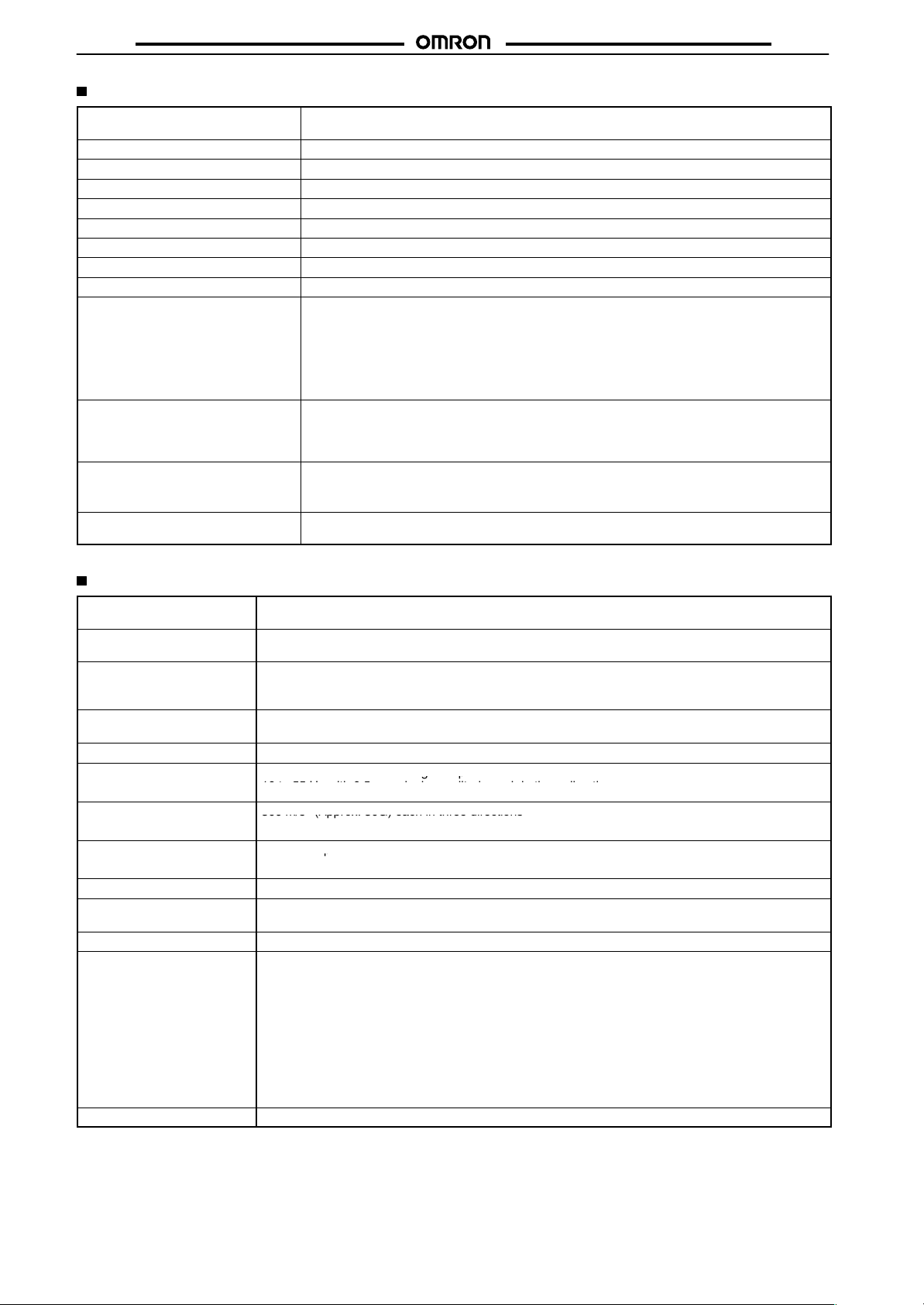
Ratings
Rated supply voltage 100 to 240 VAC, 50/60 Hz
Operating voltage range 85% to 110% of rated voltage
Current consumption Approx. 10 VA at 50 Hz, 240 VAC; approx. 6 W at 24 VDC *
Max. counting speeds (CP1, CP2) 30/1k/5k/10 kcps (separate setting for CP1 and CP2)
Compensation and gate input Set to the faster of the CP1 and CP2 max. counting speeds
Reset Min. pulse width for external reset: 1 or 20 ms, also manual reset
Batch count reset Min. pulse width: Approx. 20 ms
Key protection Response time: 1 s
One-shot time 10, 50, 100, 200, 500, and 1,000 ms (separate setting for stages 1 and 2)
Count, compensation, reset, batch
count reset, and gate inputs
Key protection input No-voltage input
Control outputs
External power supply 160 mA, 12 VDC ±10% (5% ripple max.)
*When power is turned ON, approx. 8 A inrush current flows for about 2 ms. (24 VDC, 240 VAC)
24 VAC/12 to 24 VDC (contains 20% ripple max.)
No-voltage input
ON impedance: 1 kΩ max. (Approx. 2 mA when 0 kΩ)
ON residual voltage: 2 V max.
OFF impedance: 100 kΩ max.
Voltage input (input resistance: approx. 4.7 kΩ)
High level: 4.5 to 30 VDC
Low level: 0 to 2 VDC
ON impedance: 1 kΩ max. (Approx. 2 mA when 0 kΩ)
ON residual voltage: 1 V max.
OFF impedance: 100 kΩ min.
Contacts: 3 A at 250 VAC, resistive load (cos φ = 1)
Transistor output: Open collector 100mA at 30 VDC max. residual voltage 2 V max. (Approx.
1 V)
80 mA, 24 VDC ±10% (5% ripple max.)
Characteristics
Insulation resistance 100 MΩ min. (at 500 VDC) (between current-carrying terminal and exposed non-current-carrying metal
Dielectric strength 2,000 VAC, 50/60 Hz for 1 min (between current-carrying terminal and exposed non-current-carrying
Impulse withstand voltage 3 kV (between power terminals) for 100 to 240 VAC type, 1 kV for 24 VAC/12 to 24 VDC
Noise immunity ±2 kV (between power terminals) and ±600 V (between input terminals), square-wave noise by noise
Static immunity Malfunction: 8 kV; destruction: 15 kV
Vibration resistance
Shock resistance
Life expectancy
Weight Approx. 270 g
Ambient temperature Operating: –10°C to 55°C (with no icing)
Ambient humidity Operating: 35% to 85%
EMC (EMI): EN50081-2
Case color Light gray (Munsell 5Y7/1)
parts, and between non-continuous contacts)
metal parts)
4.5 kV (between current-carrying terminal and exposed non-current-carrying metal parts for 100 to 240
VAC type, 1.5 kV for 24 VAC/12 to 24 VDC.
simulator (pulse width: 100 ns/1 µs, 1-ns rise)
10 to 55 Hz with 0.75-mm single amplitude each in three directions
10 to 55 Hz with 0.5-mm single amplitude each in three directions
300 m/s2 (Approx. 30G) each in three directions
100 m/s2 (Approx. 10G) each in three directions
10 million operations min.
100,000 operations min. 5 A at 250 VAC in load resistance)
Storage: –25°C to 65°C (with no icing)
Emission Enclosure: EN55011 Group 1 class A
Emission AC Mains: EN55011 Group 1 class A
(EMS): EN50082-2
Immunity ESD: EN61000-4-2:4 kV contact discharge
8 kV air discharge
Immunity RF-interference: ENV50140: 10 V/m (Amplitude-modulated, 80 MHz to 1 GHz)
10 V/m (Pulse-modulated, 900 MHz)
Immunity Conducted Disturbance: ENV50141: 10 V (0.15 to 80 MHz)
Immunity Burst: EN61000-4-4:2 kV power-line
2 kV I/O signal-line
4
Page 5
H7BR
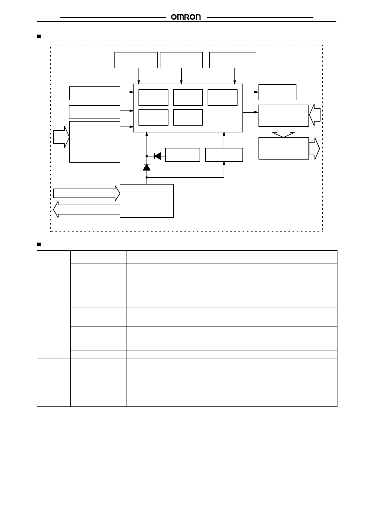
Block Diagram
H7BR
LCD drive
clock generator
Function setting
circuit
Key switch circuits
Input circuits
(CP1, CP2, compensation, gate,
reset, batch count
reset, key protection)
AC (DC) input
Power circuits *
External power supply
* Power supply is insulated from I/O.
ROM
Count
circuits
System clock
generator
RAM
Control
circuits
Battery
LCD reference
voltage generator
LCD driver
One-chip
microcomputer
Power outage
detector
LCD
No-contact outputs
inverter (DIP switch
pins 1,2)
Output circuits
(OUT, batch output)
I/O Functions
Inputs CP1/CP2 Count signal inputs.
Reset Resets present value. (to zero in Up modes, to preset with 1-stage models in Down mode, and
Compensation input
(±Range type)
Batch count reset
(Standard type)
Key protection Makes keys inoperative according to key protection level.
Gate Inhibits counter operation when gate input is ON.
Outputs OUT 1.2 Outputs made according to designated output mode when corresponding preset is reached.
Batch output
(Standard type)
Up, Down, and Up/Down (command, individual, or quadrature) inputs accepted.
to preset with 2-stage models.)
Count inputs are not accepted while reset input is ON.
Reset indicator lit while reset input is ON.
On rising edge of up count signal, present count is reset to compensation value and, therefore,
count inputs are accepted even if the compensation input is set to ON (not effective for down
count signals.)
Resets batch count to zero and batch output turns OFF.
Signals are taken in on the ON edge.
Batch count signals are not accepted while batch count reset is ON.
Key protection indicator lit while key protection input is ON.
Effective when power supply is turned off.
Effective when protect terminals are shorted.
Outputs inhibit on the teaching mode.
Outputs made when batch counter is up to preset number of batches.
Batch output remains ON until batch count reset goes ON.
When the number of batches is set to zero, batch counting is performed but batch outputs are
not made.
Batch counter counts the number of completed counts to the preset for 1-stage models and to
preset 2 for 2-stage models.
5
Page 6
H7BR
Engineering Data
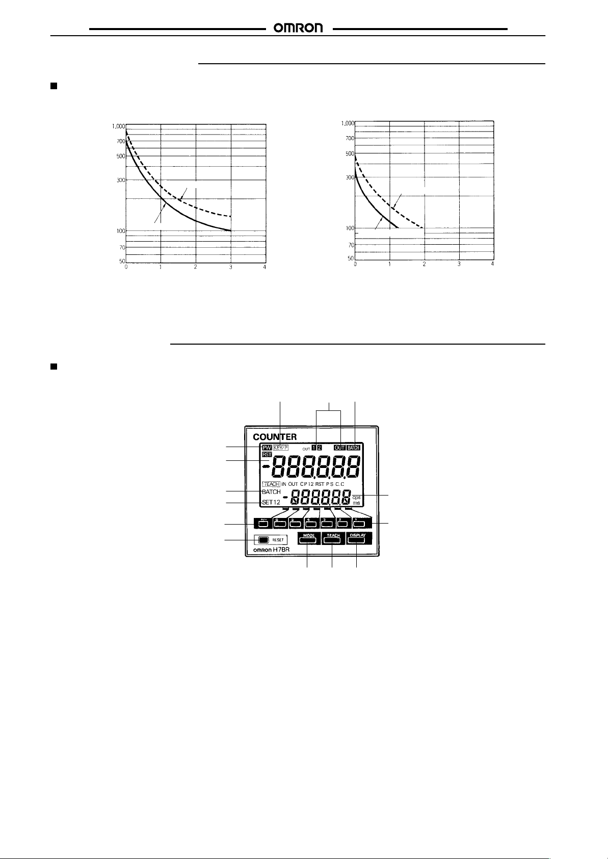
Life Expectancy of Contacts
Electrical Life Expectancy
(Resistive Load)
H7BR
Electrical Life Expectancy
(Inductive Load)
3
No. of operations (x 10 )
250 VAC (cos φ = 1)
Reference: A current of 0.15 A max. can be switched at 125 VDC (cos φ =1) and a current of 0.1 A
max. can be switched if L/R = 7 ms. In both cases, a life of 100,000 operations can be expected.
Nomenclature
Front View
Indicator
1. Power indicator
2. Key protection indicator
3. Control output indicator
OUT: 1 stage
OUT1, OUT2: 2 stages
4. Batch output indicator
(H7BR-B only)
5. Present value
(character height: 12 mm)
(Zeroes suppressed)
6. Set value
(character height: 8 mm)
(Indicates data in function setting
mode)
7. Set value 1,2 stage indicator.
8. Batch indicator
(Displays batch count indicator.)
3
30 VDC (cos φ = 1)
No. of operations (x 10 )
250 VAC (cos φ = 0.4)
Load current (A) Load current (A)
30 VDC (L/R = 7 ms)
Operation Key
2
1
5
8
7
10
15
3 4
12 13 1114
9. Increment Keys (1 to 6)
(Used to change the
corresponding digit of the set
value. Used to change data in the
function setting mode.)
10. Code Key (H7BR-C type only)
(Changes ±code of setting value.)
11. Display Key
(Switches to the batch count,
teaching mode, setting displays.
6
For 2 stage model, switch set value
1,2.)
12. Batch Key (H7BR-B type only)
9
(Switches to the batch display.)
13. Teaching Key (H7BR-C type only)
(Switches to the teaching mode.)
14. Mode Key
(Switches from run mode to
function setting mode. Changes
items in the function setting mode.
15. Reset Key
(Resets present value and
outputs.)
6
Page 7
H7BR
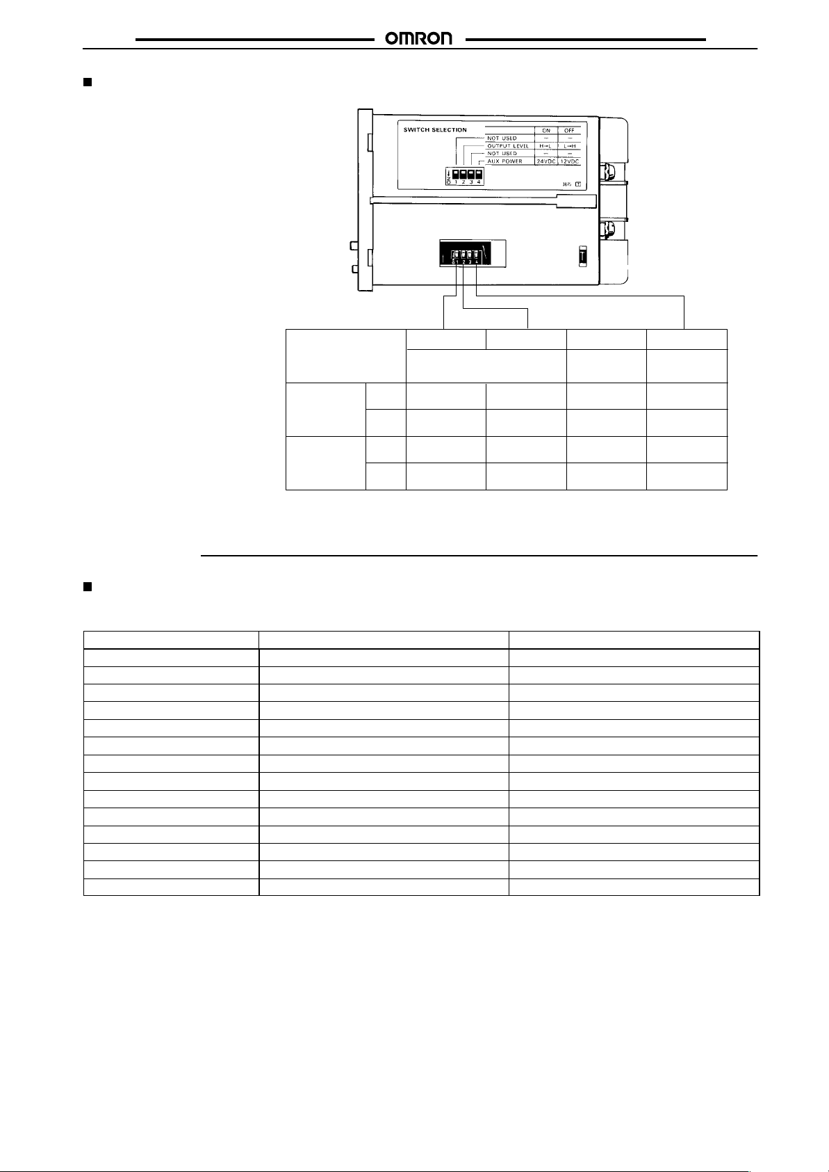
Side View
Dip switch
Models
One-stage
Two-stage
Switch
No.
OFF
ON
OFF
ON
1234
Operation of each transistor
output when count up
---
---
Output 1
OFF to ON
Output 1
ON to OFF
Output
OFF to ON
Output
ON to OFF
Output 2
OFF to ON
Output 2
ON to OFF
Invalid
---
---
---
---
H7BR
External
power supply
12 VDC
24 VDC
12 VDC
24 VDC
Note: All DIP Switches are set to OFF at the factory.
Operation
Factory Settings
The following table shows the counter settings when it is shipped. Please change the settings as necessary to suit the system before operation.
Settings and the display receive power from the internal battery and are therefore unaffected by external power interruptions.
Model
Present value 0 0
Presets 0 0
Batch present count 0 ---
Batch setting count 0 ---
Input mode Up Up/Down C (quadrature)
Output mode N K
Output 2 time (Hold) 1,000 ms
Output 1 time (2-stage only) Hold 1,000 ms
CP1 and CP2 counting speeds 30 cps 30 cps
Min. reset time 20 ms 20 ms
Decimal point Far right (no fractions) Far right (no fractions)
Prescale 1,000 1,000
Compensation count value --- 0
Key protection level KP-1 KP-1
Note: With the initial settings, there will be no output even if the power supply is connected. External inputs and outputs cannot be used
without a power supply.
H7BR-B H7BR-C
7
Page 8
H7BR
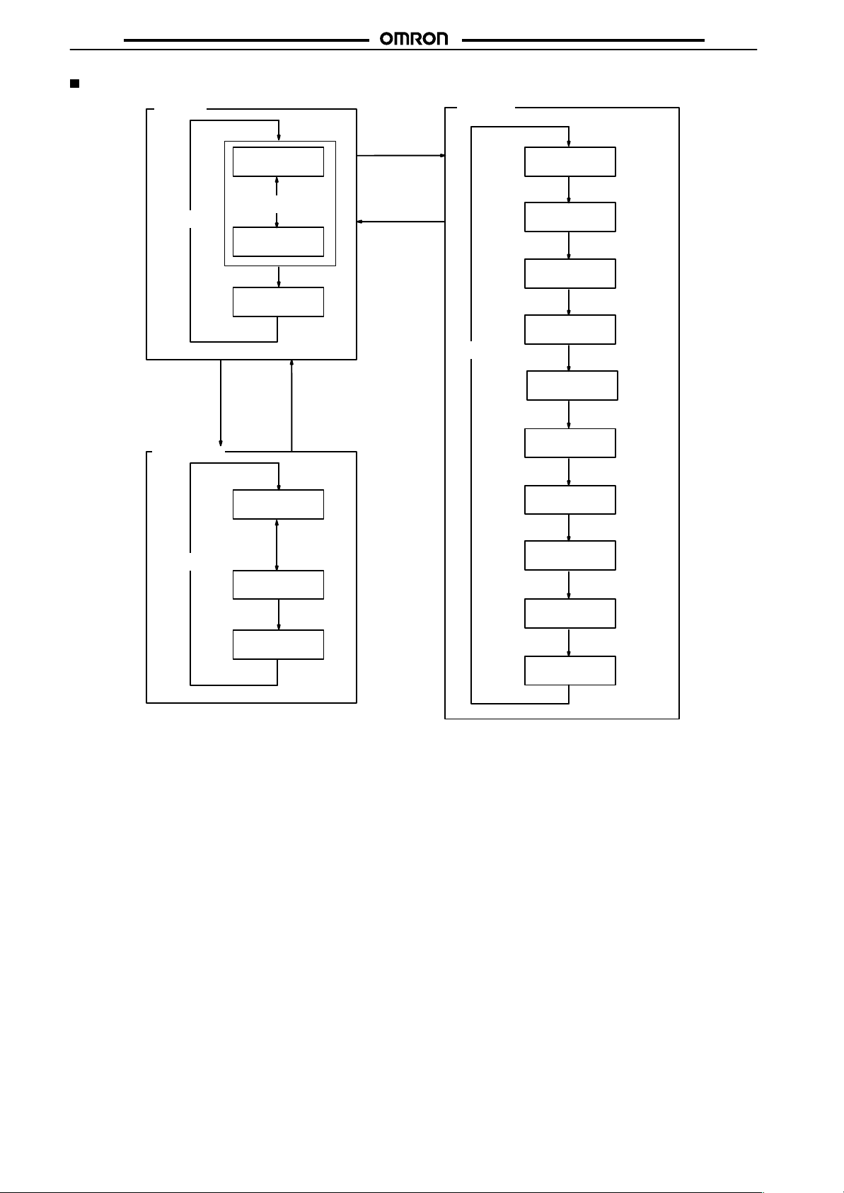
Operational Overview
Run mode
Present value,
set value 1
Press the
MODE Key
H7BR
Setting mode
Input mode
Press the
DISPLAY Key
Press the
TEACH key
Teaching mode
Press the MODE
or TEACH Key
Press the
DISPLAY Key
Present value,
set value 2
Batch count value
Present value
Press the MODE
or TEACH Key
Present value,
set value 1
Press the MODE
or TEACH Key
Present value,
set value 2
Press the
BATCH key
Press the
DISPLAY Key
Press the
DISPLAY Key
Press the
MODE Key
Output mode
Output 2 time
Output 1 time
CP1 and CP2
Count speed
Min. reset time
Decimal point
Prescale value
Compensation
count value
Key protection level
Press the
MODE Key
Press the
MODE Key
Press the
MODE Key
Press the
MODE Key
Press the
MODE Key
Press the
MODE Key
Press the
MODE Key
Press the
MODE Key
Note: Set values are changed with the Increment
Keys (1 to 6).
8
Page 9
H7BR
g
p
gp
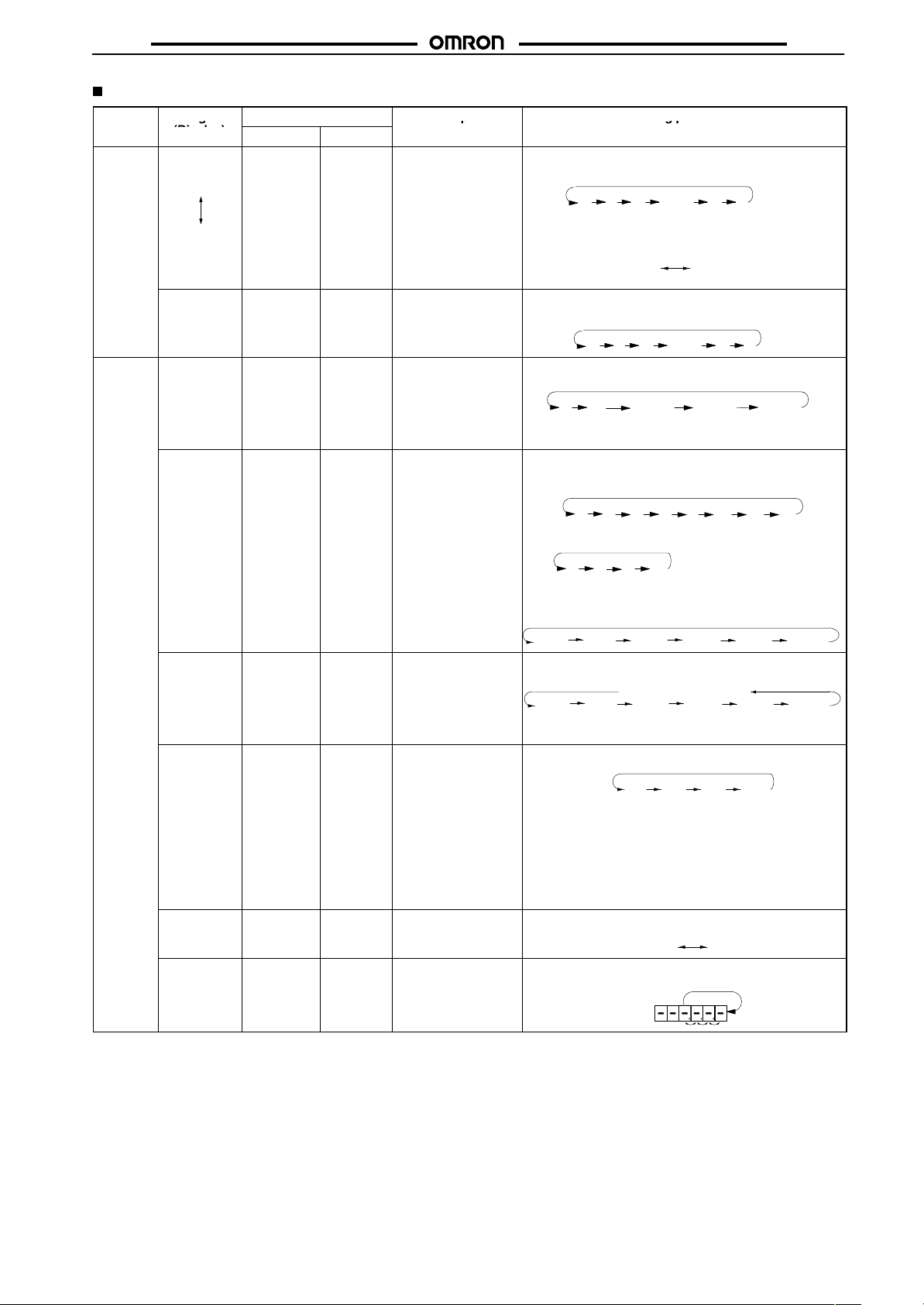
Setting Item Table
Mode Setting item
Run
mode
Function
setting
mode
(Display)
Set value 1
(SET1)
Set value 2
(SET2)
Batch count
set value
Input mode
(IN)
Output mode
(OUT)
Output time
1 (2-stage
model only)
(OUT)
CP1 and
CP2 Count
speed
(CP1, CP2)
Min. reset
time
(RST)
Decimal
point
(------)
Applicable model
H7BR-Bj H7BR-Cj
Yes Ye s Compared to the
Yes No Batch output is
Yes Ye s Determines the input
Yes Ye s Determines the form
Yes Ye s Determines the
Yes Ye s Switches the count
Yes Ye s Determines the initial
Yes Ye s Determines the
Description Setting procedure
present value,
determines the
timing of the control
output according to
the output mode. The
DISPLAY Key
switches between
set values 1 and 2.
(2-stage model only.)
turned ON when the
set number of times
is counted.
mode selecting from
Up, Down, Up/Down
modes.
of the control output.
(Refer to the present
value vs. output
diagrams on pages
15 to 18.)
Determines the
output time for
control output
(Output 2).
output time of the
control output (OUT
1) for 2-stage model
counters.
input filter to protect
against errant counts
due to interference.
signal width of the
external reset.
decimal point
position of the
present and set
values.
H7BR
Sequence when changing a digit using the
Keys (1 to 6).
08912
Press the Code Key (+/–) to change the plus or
minus sign of the set value if the model is the
H7BR-C.
Sequence when changing a digit using the
Keys (1 to 6).
(+) (blank) (-)
08912
Press keys 1 to 6 to change the mode.
u* d* udĆa udĆb udĆc
(Up) (Down) (Up/Down A) (Up/Down B) (Up/Down C)
*H7BR-B only.
Press keys 1 to 6 to change the mode.
H7BR-B
nf cR p Q aK
(N) (F) (C) (R) (K) (P) (Q) (A)
H7BR-C
Kdl h*
(K) (D) (L) (H)
Press keys 1 to 6 to change the Output 2 time. (Applicable to output modes C, R, K, P, Q, and A only.
10ms 50ms 100ms 200ms
Press keys 1 to 6 to change the set value.
10ms 50ms 100ms 200ms
*H7BR-BW only.
Press keys 1 to 6 to change the set value.
The response speeds of the gate input and com-
•
pensation input are both set to the count speed of
CP1 or CP2, whichever is faster.
• The CP1 and CP2 count speed must be set to the
same value only when the H7BR is in Up/Down C
input mode.
Press keys 1 to 6 to change the set value.
Move the decimal point position with keys, 1 to 6.
......
Ć
......
*
2-stage model only.
*
500ms
hold (self holding)
30 1K sK
(30cps) (1kcps) (5kcps) (10Kcps)
(1 ms) (20 ms)
120
*
500ms
10K
1000ms
1000ms
9
Page 10
H7BR
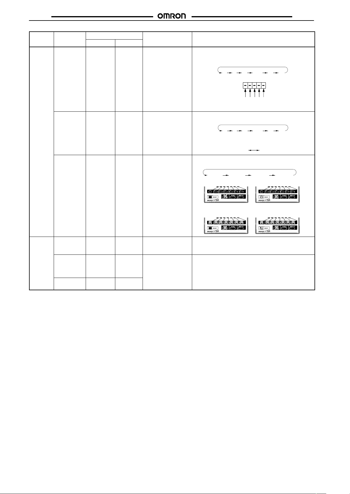
Mode Setting procedureDescriptionApplicable modelSetting item
Mode Setting procedureDescription
Function
setting
mode
Setting item
(Display)
(Display)
Prescale
value
(PS)
Compensation count
value
(C.C)
Key
protection
level
H7BR-CjH7BR-Bj
Yes Ye s Can calculate and
display a physical
parameter (volume,
length, etc.) from the
present value. For
example, if one count
input represented a
movement of 0.02
mm, the prescale
value would be 0.02.
Values from 0.001 to
99.999 are possible.
No Ye s Use compensation
input to change the
count value to set
value.
Yes Ye s Locks certain keys to
prevent accidental
operation. The key
protection level, kP-1
to kP-4, determines
which keys are
locked when the key
protection input is
ON. The locked keys
are crossed out in
the diagram on the
right.
H7BR
Change the value of the digits with the corresponding
keys, 1 to 5.
012 8 9
Change the value of the digits with the corresponding
keys, 1 to 6.
012 8 9
Press the Code Key to change the plus or minus sign of
the set value.
Sequence when changing the key protection level using
the Increment Keys (1 to 6).
(+) (blank) (-)
KpĆ1 KpĆ2 KpĆ3 KpĆ4
<KP-1> <KP-2>
.....
12345
.....
Ć
<KP-4><KP-3>
Teaching
Mode
Note: 1. Settings changed in setting mode are not effective until run mode is entered.
Prescale
value
(PS)
Set value 1
(two-stage
model only)
(SET1)
Set value 2
(SET2)
2. Control output is prohibited in teaching mode. Output is OFF in coincidence-ON operation and ON in coincidence-OFF operation.
3. The TEACH Key is disabled when the H7BR is turned OFF, when no teaching is possible. Other functions are enabled regardless of
whether the H7BR is turned ON or OFF.
No Ye s --- By setting the conversion count value and pressing the
No Ye s
No Ye s
--- By pressing the TEACH Key, the Present value is set as
TEACH Key, the prescale value is automatically
calculated and set.
the set value.
10
Page 11
H7BR
Examples
Run Mode
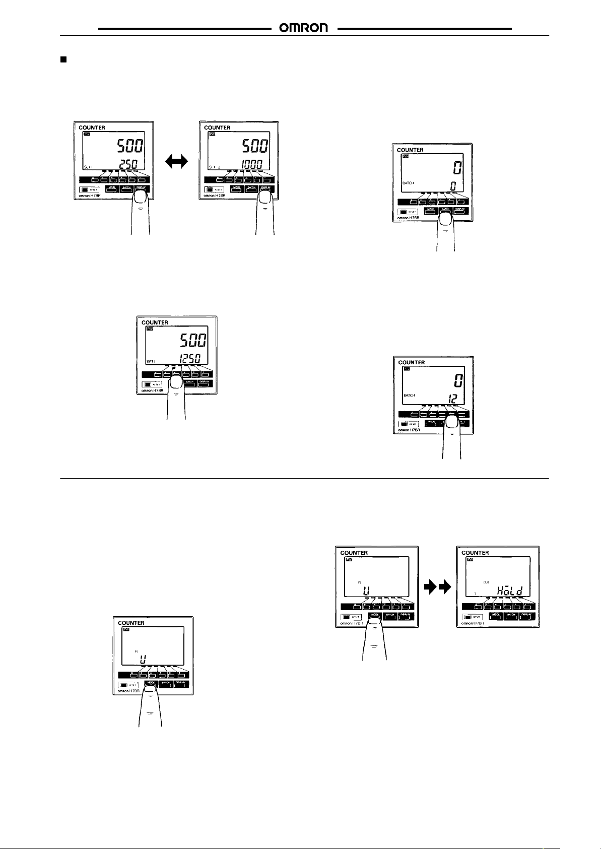
Changing the Set Value
1. Press the DISPLAY Key to change the displayed preset value 1
and 2 during operation.
2. Change the set value from 250 to 1,250.
• Pressing keys 1 through 6 increments the corresponding column
by1.
• Non-significant zeros are normally not shown on the set value
display.
H7BR
Batch Set Value Change
(Applicable to Standard Models Only)
1. Selecting Batch Count Display
Switch the count display over to batch count display.
Press the BATCH Key.
2. Batch Set Value Change
Change the batch set value while the batch count is displayed.
Pressing keys 1 through 6 increments the corresponding column by
1.
• Non-significant zeros are normally not shown on the set value
display.
In order to switch the batch count display over to the count
display, press the DISPLAY Key.
Setting Mode
Changing Settings in the Function Setting Mode
1. Press the MODE Key to switch from run mode to setting mode.
• The Counter will continue operation if switched from run
mode to function setting mode during operation.
• The MODE Key will be locked if the key protection function is
enabled.
• Settings changed in the function setting mode are not
effective until run mode is entered. As the operating
conditions will change in this case, always reset operation
with the RESET Key or a reset input.
2. Press the MODE Key to scroll successively through the items
that can be set. Release the MODE Key to select the desired
item.
11
Page 12
H7BR
H7BR
3. Changing the selected item
• Press the MODE Key until the desired item appears
• Change the item setting by pressing keys 1 through 6. (Press
the DISPLAY Key to switch back from function setting mode
to run mode.)
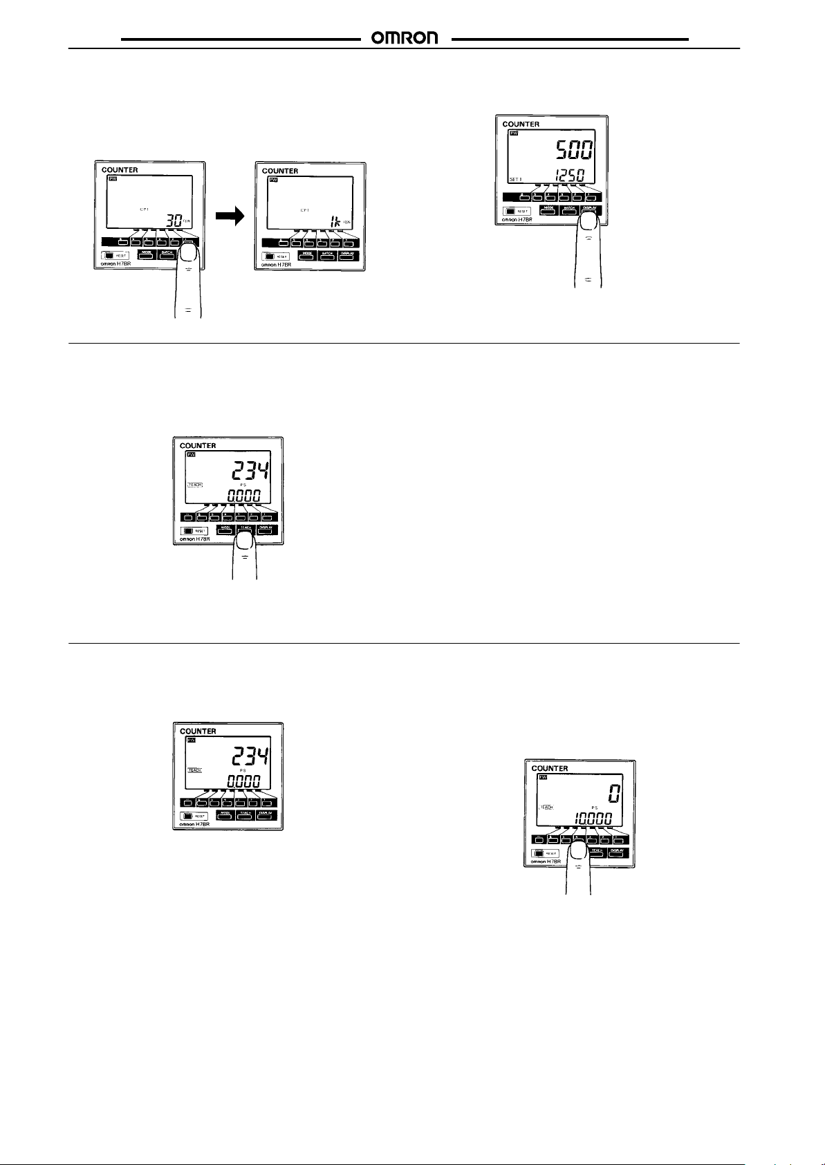
Teaching Mode (± Range Models Only)
Changing to Teaching Mode (Power Must be ON)
Change from run mode to teaching mode.
Press the TEACH Key.
• Press the DISPLAY Key to return to Run mode from Setting
mode.
If prescale teaching is not required, press the MODE Key and go to
Set Value 1 Teaching.
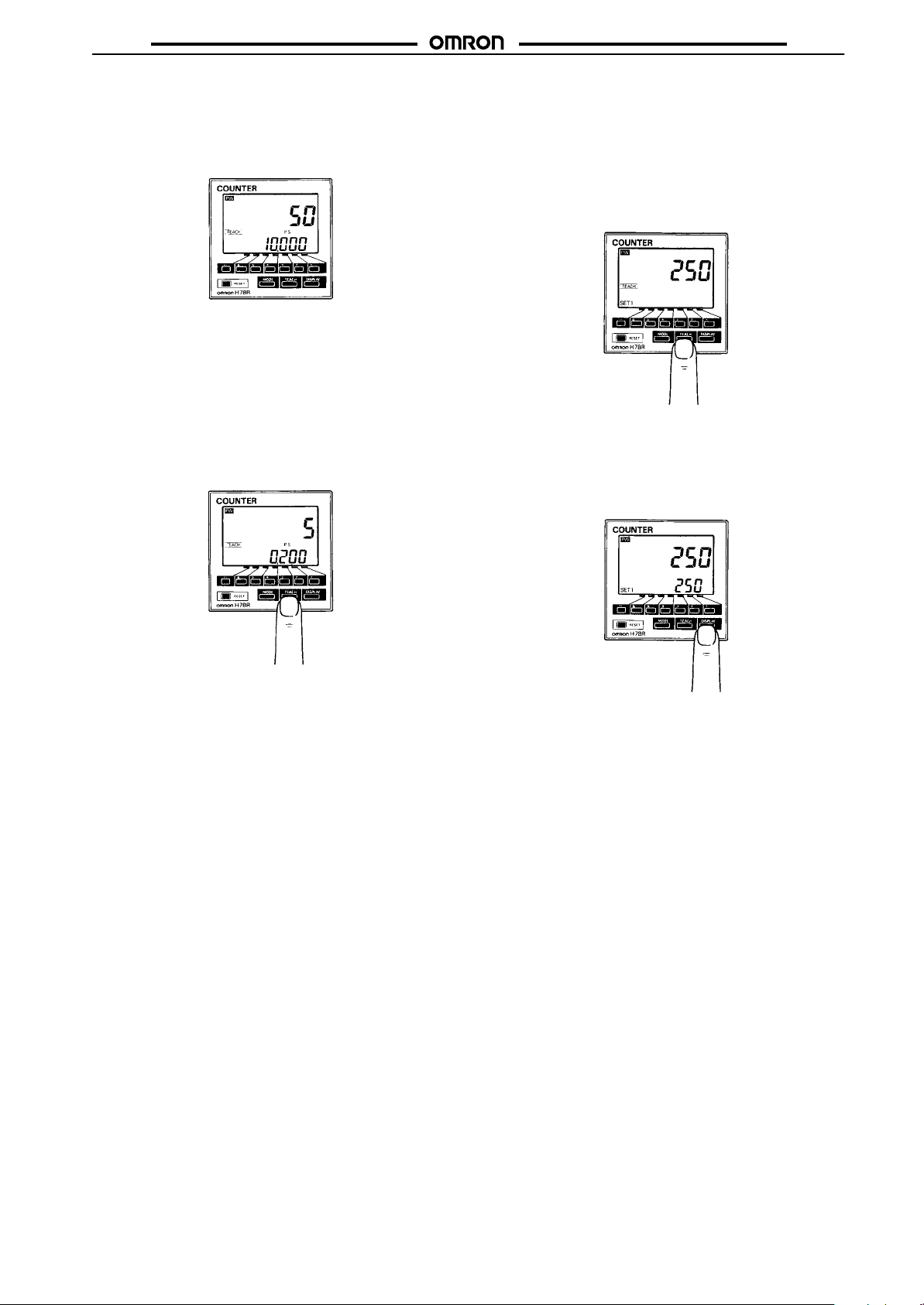
Prescale Teaching
1. Perform prescale teaching of the H7BR in teaching mode.
• The prescale display shows 0.000.
2. Set 10 cm as a converted count value, for example.
Pressing keys 1 through 6 increments the corresponding column by
1.
• By pressing one of keys 1 through 6, the counter PV (present
value) display indicates 0.
12
Page 13
H7BR
H7BR
3. Input a count signal corresponding to the conversion count value
through the external sensor.
• The display on the right side indicates that an input of 50 counts
has been input from the external sensor with the controlled
object moved 10 cm.
4. Perform prescale value teaching per count.
Press the TEACH Key. (Prescale value 0.2 = 10 cm/50)
• If the conversion count value input at step 3 is a negative value,
the prescale value will be calculated using the absolute value of
the conversion count value.
• The fraction is rounded off for prescale calculations. (It is
rounded upward when displaying negative values.)
• While the TEACH Key is pressed, the teaching prescale value
(i.e., 0.2) is displayed.
Set Value 1 Teaching
1. Press the MODE Key to perform the teaching of set value 1,
provided that the H7BR is a two-stage model.
2. Input an appropriate count signal from the external sensor.
3. Register the count value 250 as the set value, for example.
Press the TEACH Key.
• The teaching set value is displayed while the TEACH Key is
pressed.
Set Value 2 Teaching (Two-stage Models Only)
• Perform the same procedure as Set Value 1 Teaching above.
Press the DISPLAY Key to return to run mode from teaching
mode.
13
Page 14
H7BR
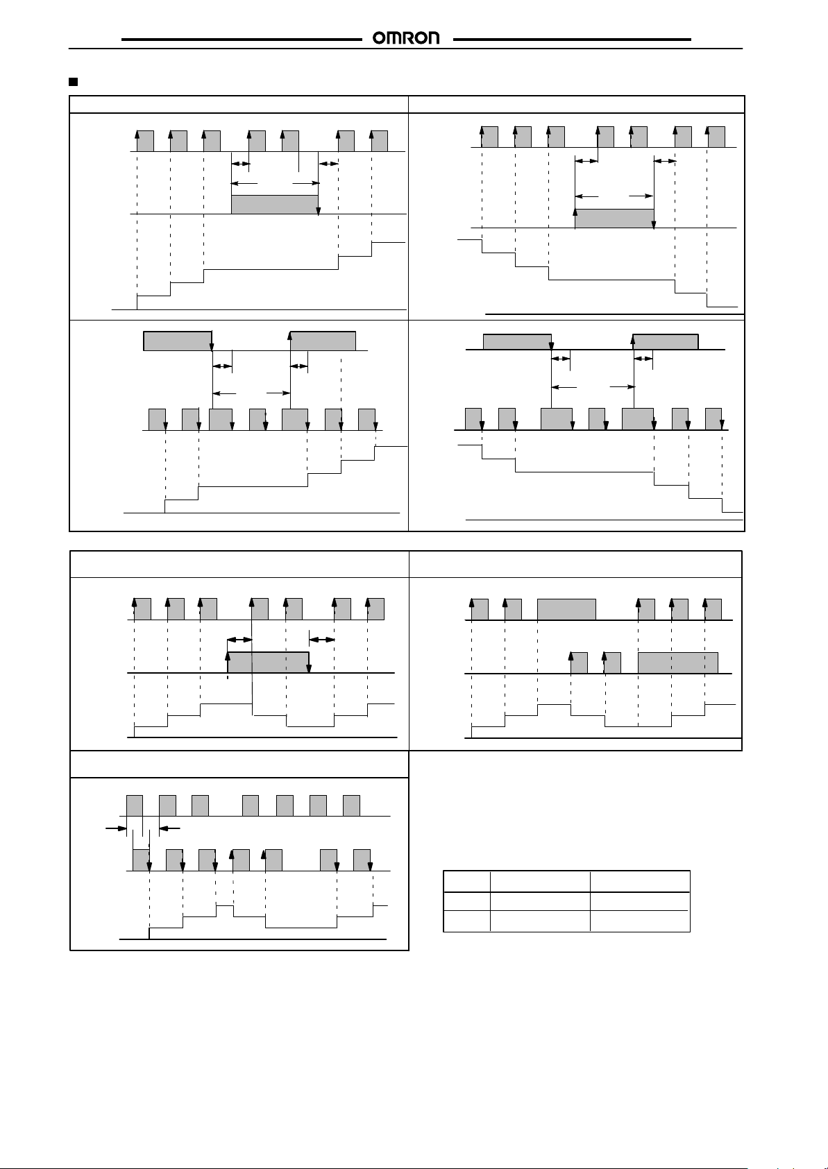
Input Modes and Count Value
Up (increment) mode Down (decrement) mode
Count
H
input
CP1
Gate
input
CP2
Count
Gate
input
CP1
Count
input
CP2
Count
L
A A
H
L
2
1
0
0
H
L
A A
H
L
1
0
0
Inhibit
3
Inhibit
2
H7BR
Count
H
input
CP1
Gate
input
CP2
5
4
Count
Gate
input
CP1
Count
input
CP2
5
4
3
Count
L
A A
H
L
n
n-1
n-2
0
H
L
A A
H
L
n
n-1
0
Inhibit
n-3
n-4
n-5
Inhibit
n-2
n-3
n-4
n-5
CP1
CP2
Count
Count
Up/Down A Command input mode Up/Down B Individual input mode
H
L
A
H
L
3
2
1
0
Up/Down C Quadrature input mode
H
L
BB B B
H
L
3
2
0
1
2
A
3
2
1
2
1
3
2
H
CP1
L
H
CP2
L
3
2
Count
Note 1 A: Minimum signal width; B: Must be at least 1/2 of
Note 2 Set the same counting speed for CP1 and CP2 when
Note 3 H and L
1
0
minimum signal width. Signals may not be counted
if the minimums for A and B are not met.
in Up/Down C mode.
Signal No-voltage input Voltage input
H
L
Short-circuit
Open circuit
2
11
4.5 to 30 VDC
0 to 2 VDC
3
2
14
Page 15
H7BR
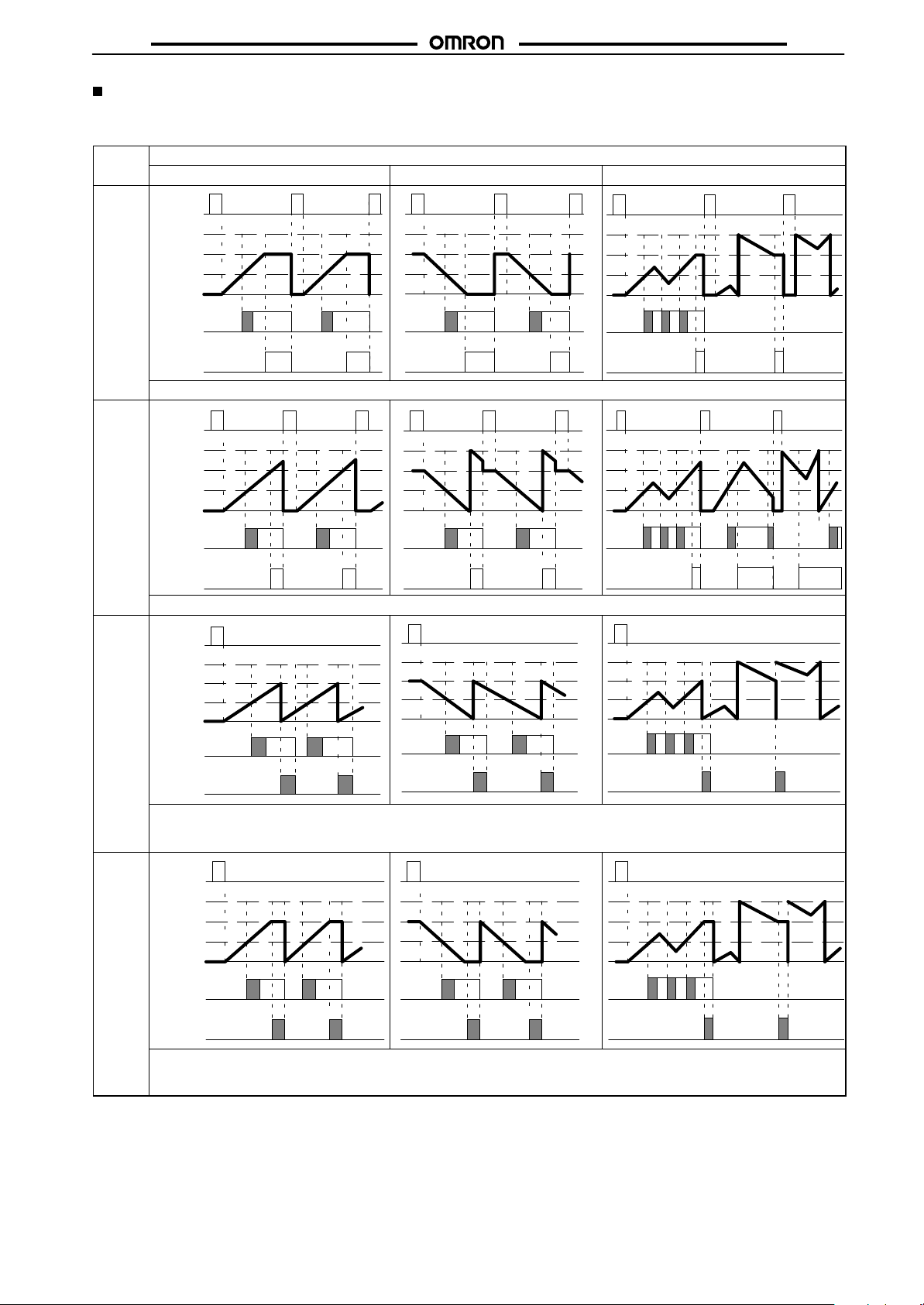
Input/Output Mode Setting
H7BR-B
Output 2 operation applies for 1-stage models only.
Output
mode Up Down Up/Down A.B.C
N
Reset
999,999
Preset 2
Preset 1
0
Output 1
Output 2
Outputs and present value display are maintained until reset.
F
Reset
999,999
Preset 2
Preset 1
0
Input mode
H7BR
Output 1
Output 2
Present value display runs continuously. Outputs are maintained until reset.
C
Reset
999,999
Preset 2
Preset 1
0
Output 1
Output 2
Present value is placed in reset start status as soon as count up is reached. The count up is not displayed. Outputs are
1-shot and operate repeatedly. Output 1 is self-holding, and goes off after expiration of the 1-shot period for Output 2.
One-shot time periods for Output 1 and 2 are independent.
R
Reset
999,999
Preset 2
Preset 1
0
Output 1
Output 2
Present value is placed in reset start status as soon as count up is reached. Outputs are 1-shot and operate repeatedly.
Output 1 is self-holding, and goes off after expiration of the 1-shot period for Output 2. One-shot time periods for Output 1
and 2 are independent.
15
Page 16
H7BR
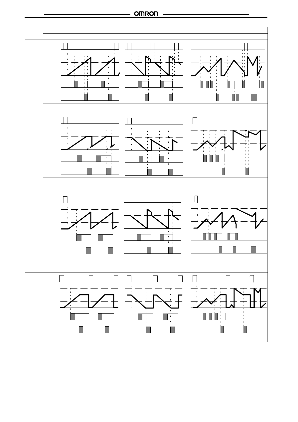
Output Input mode
mode Up Down Up/Down A.B.C
K
Reset
999,999
Preset 2
Preset 1
0
Output 1
Output 2
Present value runs continuously. Output 1 is self-holding, and goes off after expiration of the 1-shot period for Output 2.
One-shot time periods for Output 1 and 2 are independent.
P
Reset
999,999
Preset 2
Preset 1
0
H7BR
Output 1
Output 2
Present value display does not change during 1-shot time period, but reset start status is returned to as soon as count is
reached. Outputs are 1-shot and operate repeatedly. Output 1 is self-holding, and goes off after expiration of the 1-shot
period for Output 2. One-shot time periods for Output 1 and 2 are independent.
Q
Reset
999,999
Preset 2
Preset 1
0
Output 1
Output 2
Present value runs continuously through 1-shot time period and returns to reset start status immediately afterward. Outputs
are 1-shot and operate repeatedly. Output 1 is self-holding, and goes off after expiration of the 1-shot period for Output 2.
One-shot time periods for Output 1 and 2 are independent.
A
Reset
999,999
Preset 2
Preset 1
0
16
Output 1
Output 2
Present value and output 1 maintain status until reset. Output 1 and 2 operate independently.
Page 17
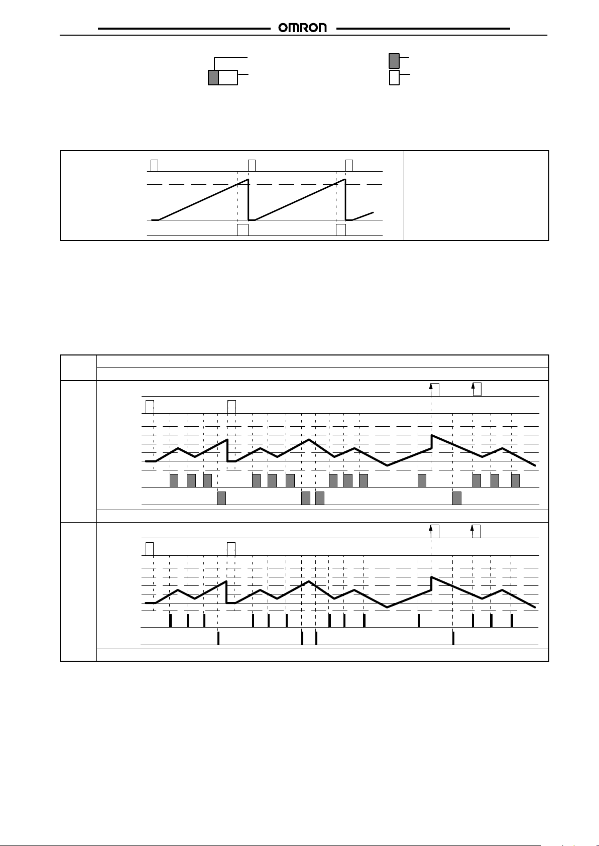
H7BR
H7BR
One-shot output from Output 1
One-shot output from Output 2
Self-holding output Self-holding output
One-shot outputs can be set to between 10 and 1,000 ms.
Batch Counter Operation
The batch counter counts the number of times set value is reached for 1-stage models, and the number of times set 2 is reached for 2-stage
models.
The batch count output holds until
Batch count reset
Batch count set
reset by the batch count reset.
The present value of the batch count
advances continuously.
value
Batch count present
value 0
Batch output
1. The batch count present value remains at 0 while the batch
count reset is ON.
2. When the batch count set value is 0, the batch count will
proceed, but there will be no output.
3. When the batch count present value exceeds 9999, it returns
to 0.
4. The batch count present value and output do not affect the
RESET Key or reset input.
5. When power is interrupted and the batch count output is ON,
the output will be ON when power returns.
6. When a batch count set value which is greater than the
present value is changed to a set value which is less than the
present value, the output will go ON.
7. If, after the output has gone ON, the set value is changed to a
set value which is greater than the present value, the output
will remain ON.
H7BR-C
Output 2 operation applies for 1-stage models only.
Output
mode Up/Down A.B.C
K
Comp.
Input mode
Reset
999,999
Comp.
Set 2
Set 1
0
-999,999
Output 1
Output 2
Present value increments and decrements within displayable range. Outputs go ON for one-shot.
D
Comp.
Reset
999,999
Comp.
Set 2
Set 1
-999,999
Output 1
Output 2
0
Present value increments and decrements within displayable range. Outputs are ON during the count is equal.
17
Page 18
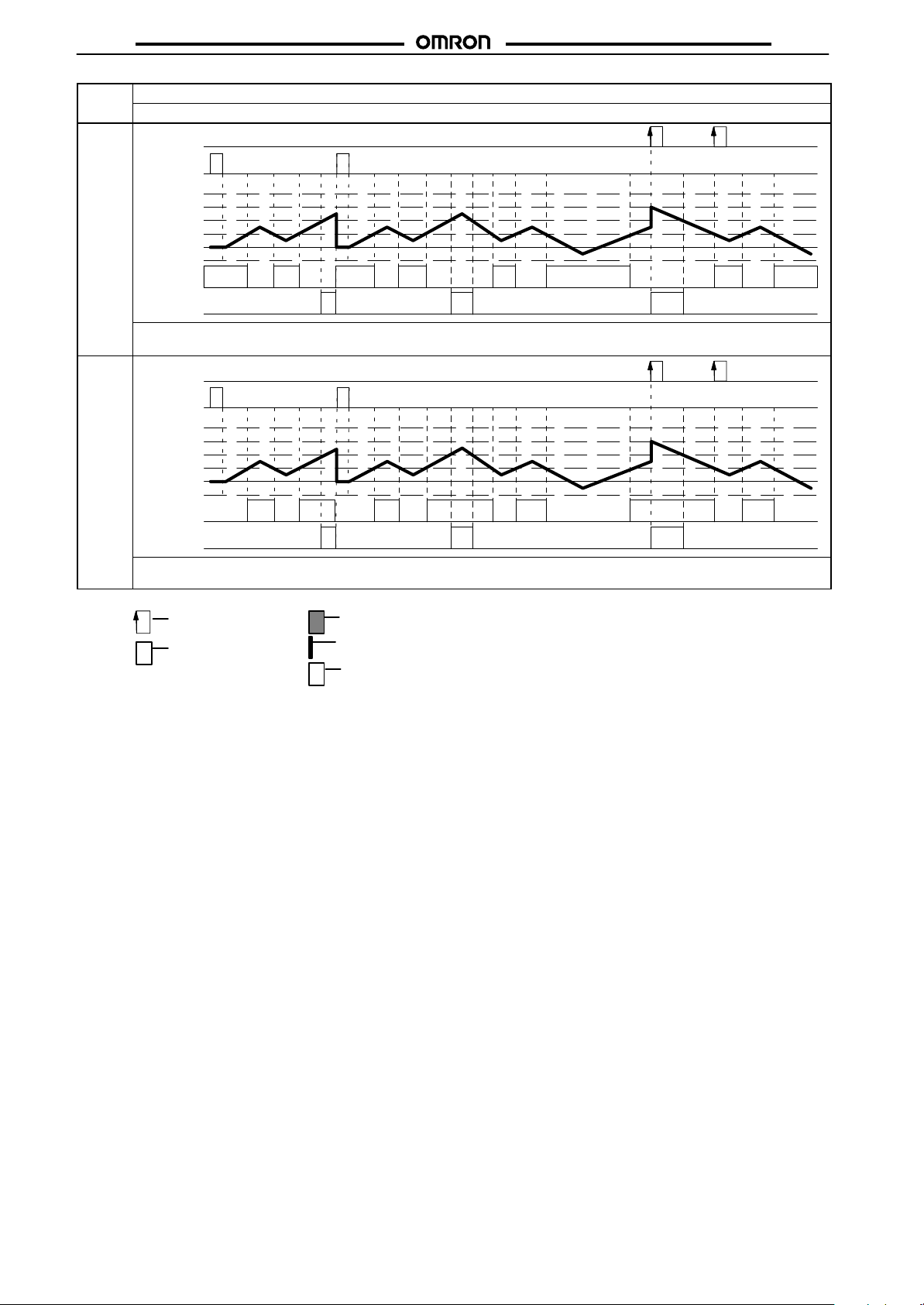
H7BR
Output Input mode
mode Up/Down A.B.C
L
H
Comp.
Reset
999,999
Comp.
Set 2
Set 1
0
-999,999
Output 1
Output 2
Present value increments and decrements within displayable range. Output 1 is ON whenever present value is less than or
equal to Set 1; Output 2 is ON whenever present value is greater than or equal to Set 2.
Comp.
Reset
999,999
Comp.
Set 2
Set 1
0
-999,999
Output 1
Output 2
Present value increments and decrements within displayable range. Output 1 is ON whenever present value is greater than
or equal to Set 1; Output 2 is ON whenever present value is greater than or equal to Set 2.
H7BR
Edge input
Level input
One-shot output
Instantaneous (equals) output
Self-holding output/level input
Note: 1. Counting inputs are not applied while the reset input is
ON.
2. One-shot outputs, when ON, are turned OFF when the
reset input goes ON.
3. One-shot outputs, when ON, are left ON for the one-shot
time period when the compensation input goes ON
4. One-shot outputs, when ON, are reset and the one-shot
output is restarted if a preset designating the output is
reached.
5. The compensation input is valid only when the present
value is being incremented.
The compensation input is also valid only for the
H7BR-Cj.
One-shot outputs can be set to between 10 and 1,000 ms.
18
Page 19
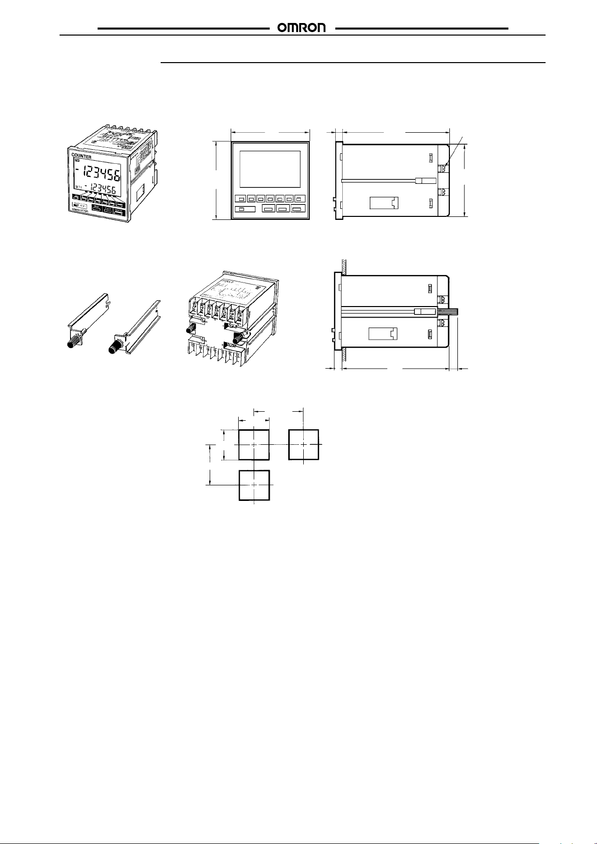
H7BR
Dimensions
Note: All units are in millimeters unless otherwise indicated.
H7BR
Flash Mounting
72
100
H7BR
M3.5 terminal screw
(effective length: 6 mm)
Flash Mounting Adapter
Panel Cutouts
Panel cutouts are
as shown at right.
(according to DIN43700).
72
82 min.
67.6
Panel
6
100 min.
+0.7
68
–0
+0.7
68
–0
100
7 + panel thickness
19
Page 20
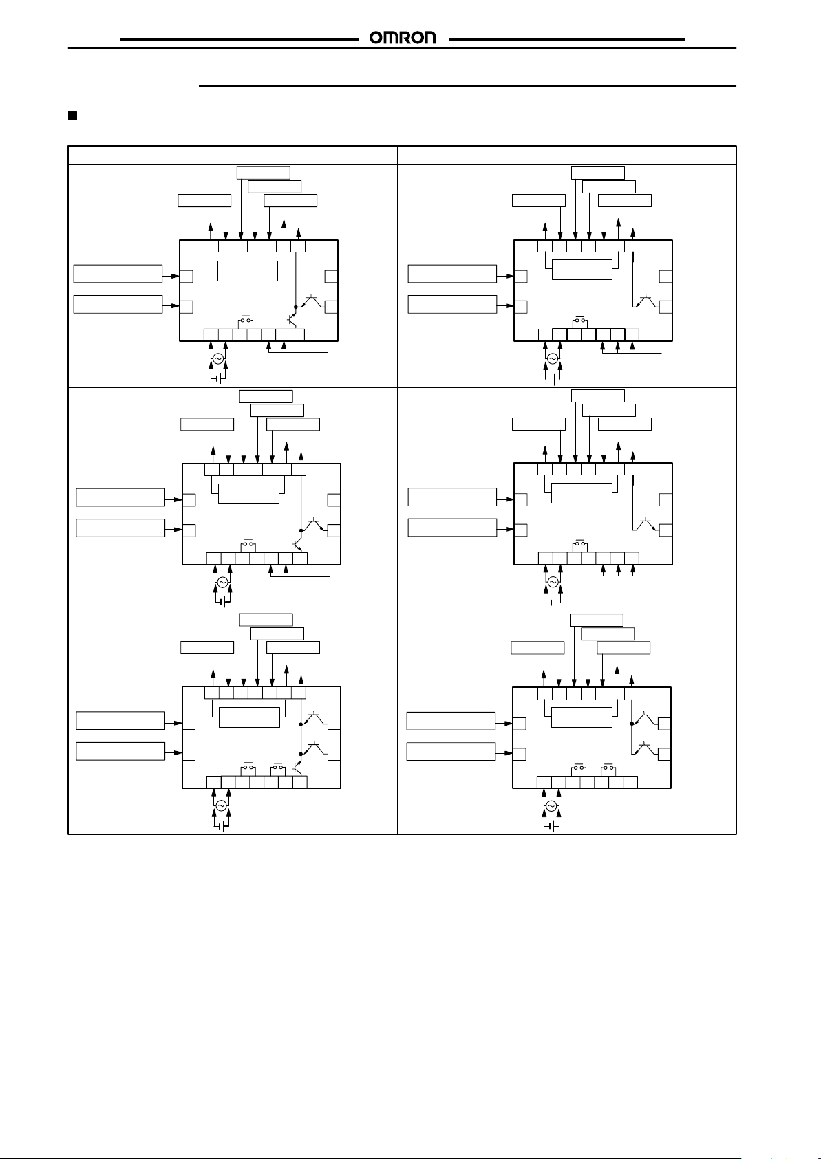
H7BR
Installation
Terminal Arrangement
H7BR
H7BR-B (standard type)
1 Stage, Contact and NPN
Transistor Outputs
H7BR-B
H7BR-BV
Batch count reset
Key protection input
1 Stage, Contact and PNP
Transistor Outputs
H7BR-BP
H7BR-BVP
Batch count reset
Key protection input
2 Stages, Contact and NPN
Transistor Outputs
H7BR-BW
H7BR-BWV
Batch counter reset
Key protection input
Reset input
15
16
(–) (+)
Reset input
15
16
Reset input
15
16
(–) (+)
CP2 input
CP1 input
Gate input
0 V
8 9 10 11 12 13 14
Sensor
(-)
power supply
OUT
1234 567
0 V
10 11 1312 14
8 9
Sensor
(-)
power supply
OUT
2
(–) (+)
0 V
10 11 1312 14
8 9
Sensor
(-)
power supply
OUT 2
2
12/24 VDC
100 to 240 VAC/24 VAC
12 to 24 VDC
CP2 input
CP1 input
Gate input
(+)
6 5 3 1
4 7
100 to 240 VAC/24 VAC
12 to 24 VDC
CP2 input
CP1 input
Gate input
OUT 1
6 5 3 1
4 7
100 to 240 VAC/24 VAC
12 to 24 VDC
(+)
OUT
Batch
12/24 VDC
Output common
OUT
Batch
12/24 VDC
Output common
OUT 1
(+)
OUT 2
Batch
17
18
Unused
17
18
Unused
17
18
Unused
Unused
H7BR-C (± range type)
1 Stage, Contact and NPN
Transistor Outputs
H7BR-C
H7BR-CV
Compensation input
Key protection input
1 Stage, Contact and PNP
Transistor Outputs
H7BR-CP
H7BR-CVP
Compensation input
Key protection input
2 Stages, Contact and NPN
Transistor Outputs
H7BR-CW
H7BR-CWV
Compensation input
Key protection input
Reset input
15
16
Reset input
15
16
Reset input
15
16
0 V
(-)
8 9
Sensor
(-)
power supply
2
0 V
8 9
Sensor
(-)
power supply
2
(–) (+)
0 V
8 9
Sensor
(-)
power supply
2
(–) (+)
CP2 input
CP1 input
Gate input
12/24 VDC
Output commonOutput common
10 11 1312 14
OUT
(+)(–)
CP2 input
10 11 1312 14
OUT
100 to 240 VAC/24 VAC
12 to 24 VDC
CP2 input
10 11 1312 14
OUT 2
100 to 240 VAC/24 VAC
12 to 24 VDC
(+)
(+)
6 5 3 1
4 7
100 to 240 VAC/24 VAC
12 to 24 VDC
CP1 input
Gate input
12/24 VDC
Output common
(+)
6 5 3 1
4 7
CP1 input
Gate input
12/24 VDC
Output common
OUT 1
(+)
OUT 2
OUT 1
6 5 3 1
4 7
Unused
OUT
OUT
17
18
17
18
17
18
Unused
Unused
Unused
Unused
20
Page 21
H7BR
H7BR
H7BR-B (standard type)
2 Stages, Contact and PNP
Transistor Outputs
H7BR-BWP
H7BR-BWVP
Batch count reset
Key protection input
Reset input
15
16
(–) (+)
CP2 input
0 V
10 11 1312 14
8 9
Sensor
(-)
power supply
OUT 2
2
100 to 240 VAC/24 VAC
12 to 24 VDC
CP1 input
Gate input
12/24 VDC
(+)
OUT 1
6 5 3 1
4 7
Output common
OUT 1
17
OUT 2
18
Batch
H7BR-C (± range type)
2 Stages, Contact and PNP
Transistor Outputs
H7BR-CWP
H7BR-CWVP
Compensation input
Key protection input
Reset input
15
16
(–) (+)
Note: Do not connect unused terminals.
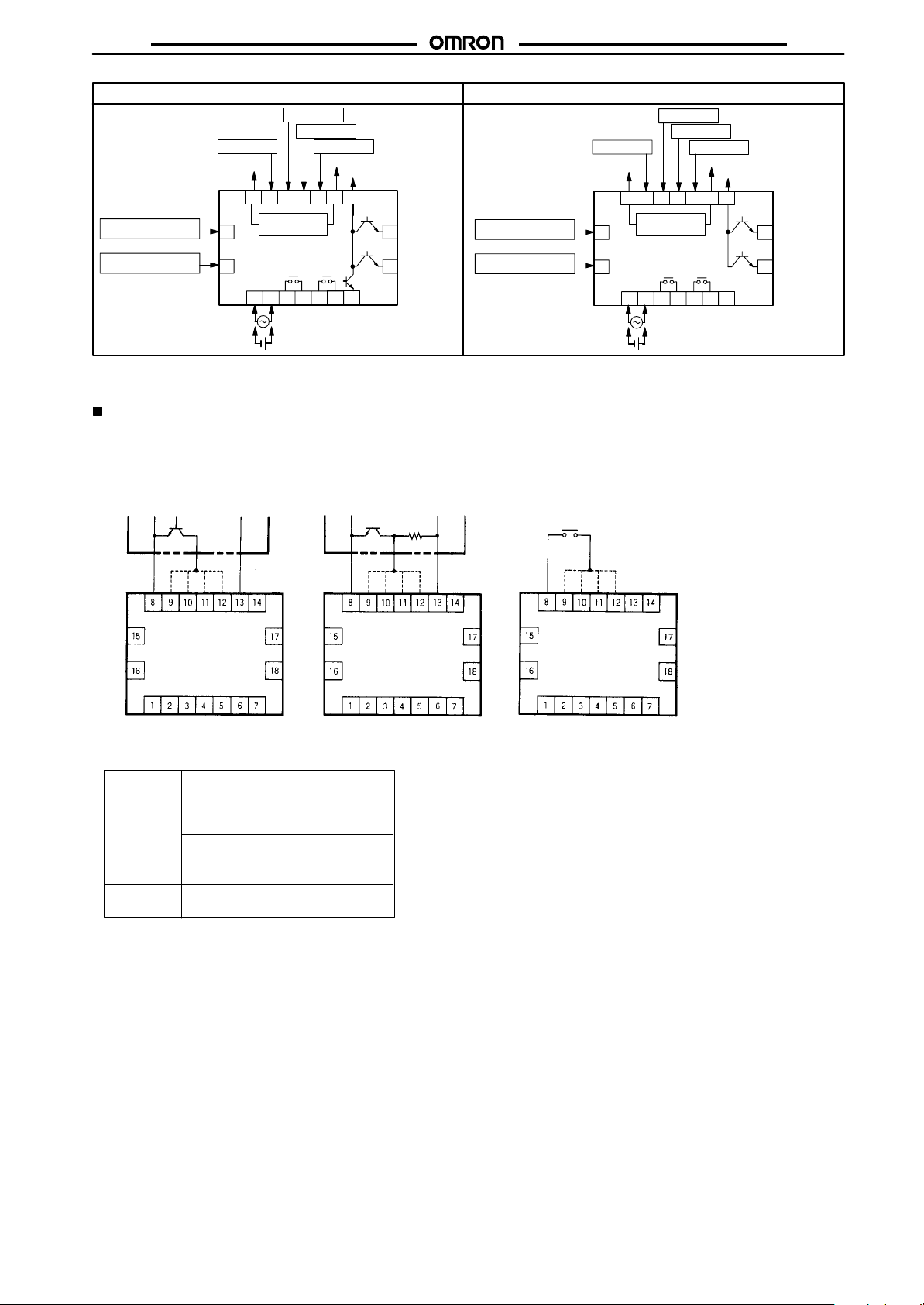
Connections
The inputs of the H7BR are no-voltage (short-circuit or open) inputs and voltage inputs.
(Key protection only for no-voltage inputs)
No-voltage Inputs
Open Collector Voltage Output Contact Input
Sensor
Sensor
0 V
8 9
Sensor
(-)
power supply
2
CP2 input
CP1 input
Gate input
12/24 VDC
Output common
10 11 1312 14
(+)
OUT 2
OUT 1
6 5 3 1
4 7
Unused
100 to 240 VAC/24 VAC
12 to 24 VDC
OUT 1
17
OUT 2
18
0 V for input
Reset input
CP2 input
CP1 input
Gate input
12/24-V output
*H: Transistor ON
No-voltage Input Signal Levels
1. High level
Transistor ON
No-contact
input
Residual voltage: 2 V max.
Impedance when ON: 1 kΩ max.
2. Low level
Transistor OFF
Impedance when OFF: 100 kΩ max.
Contact
input
Use contacts which can adequately switch 2 mA at 5 V
0 V for input
Reset input
CP2 input
CP1 input
Gate input
12/24-V output
*H: Relay ON *H: Transistor ON
0 V for input
Reset input
CP2 input
CP1 input
Gate input
12/24-V output
21
Page 22
H7BR
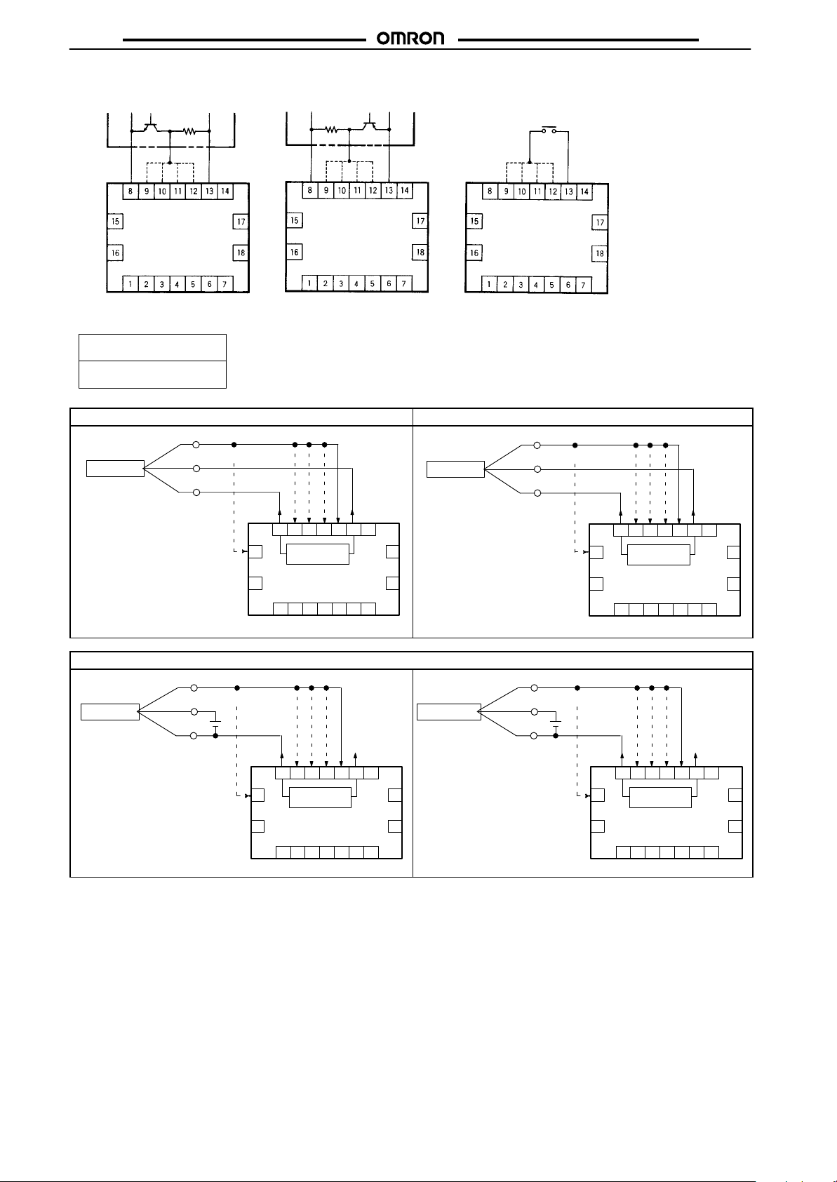
Voltage Inputs
NPN Transistor
0 V for input
Reset input
CP2 input
CP1 input
Gate input
Sensor
12/24-V output
Sensor
0 V for input
Reset input
CP2 input
CP1 input
Gate input
12/24-V output
Contact InputPNP Transistor
0 V for input
Reset input
CP2 input
CP1 input
Gate input
H7BR
12/24-V output
*H: Transistor OFF
Voltage Input Signal Levels
1. High level 4.5 to 30 VDC
2. Low level 0 to 2 VDC
3-wire DC type(NPN) 3-wire DC type (PNP)
Photoelectric
sensor
Output (black)
12 to 24 V (brown)
E3S-A/B
0 V (blue)
8 9
15
16
*Models ending in -BV have reversed logic.
Photoelectric
sensor
E3S-A/B
Output (black)
12 to 24 V (brown)
*H: Transistor ON *H: Relay ON
Photoelectric
sensor
E3S-A/B
10 11 1312 14
Sensor
(-)
power supply
H7BR-B, BV
2
4 7
17
(+)
18
6 5 3 1
Using the external power supply
Proximity
sensor
E2E-XjE
Output (black)
12 to 24 V (brown)
0 V (blue)
Output (black)
12 to 24 V (brown)
10 11 1312 14
8 9
Sensor
15
(-)
power supply
16
H7BR-BV
2
4 7
17
(+)
18
6 5 3 1
22
0 V (blue)
0 V (blue)
10 11 1312 14
8 9
Sensor
15
(-)
power supply
16
H7BR-BV
2
4 7
17
(+)
18
15
16
6 5 3 1
10 11 1312 14
8 9
Sensor
(-)
power supply
H7BR-B, BV
2
(+)
6 5 3 1
4 7
17
18
*Models ending in -BV have reversed logic.
Page 23
H7BR
Precautions
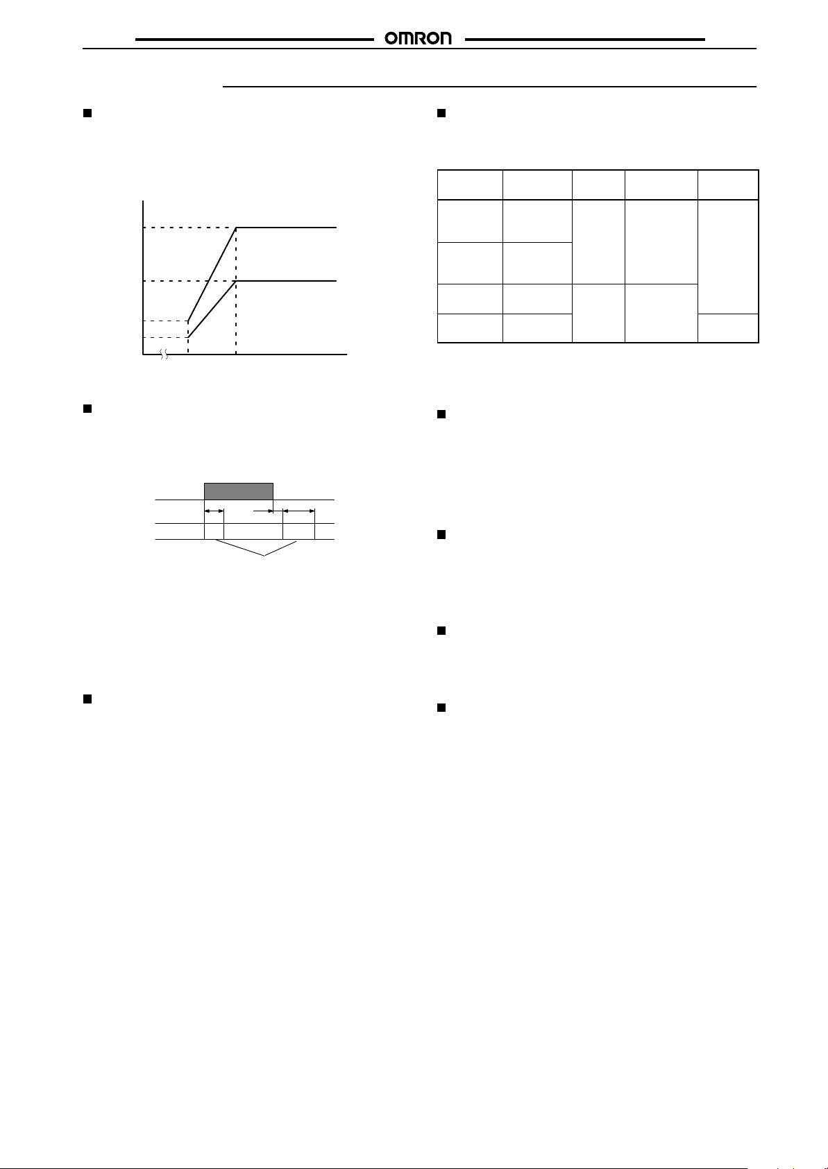
Sensor Power Supply
• The capacity of the external power supply is 160 mA at 12
VDC/80 mA at 24 VDC switchable. When using a 24 VAC/12 to
24 VDC power supply type H7BR, reduce the load with the
power supply voltage, as shown in the following diagram (When
supplying external power).
160
80
Load current (mA)
20
10
0
1710 20 25
Supply voltage (VDC)
Power Supplies
• When turning the power ON and OFF, input signal reception is
possible, unstable, or impossible as shown in the diagram below.
The unstable period will vary with power supply voltage, and the
load conditions on external power supplies.
Power
supply
Input impossible impossible
ON
OFF
0 to 50 ms
10 ms
Possible
Unstable
• A switching regulator is used in the internal circuits of counters
with 100-to-240-VAC or 12-to-24-VAC specifications, causing
an inrush current (approx. 1.5 A) to flow when power is turned on.
If the capacity of the power supply to the counter is insufficient,
the counter may not start operation. Be sure to provide adequate
capacity (recommended supply capacity; 25 W min.)
• Connect the power supply voltage through a relay or switch in
such a way that the voltage reaches a fixed value immediately.
DIP Switch Setting Changes
Any changes in the DIP switch settings while power is being supplied is invalid. Restart the power supply.
12 VDC
24 VDC
0 to 1.2 s
H7BR
Self-diagnostic Function
• The following displays will appear if an error occurs. The present
value and output enter the same status as after pressing the
RESET Key.
Display
ĆĆĆĆĆĆ*
ffffff**
e1
e2
*Displayed when the present value has fallen below the min. value
in the H7BR-C (±range type).
**Displayed when the present value has exceeded the max. value in
the H7BR-C (±range type).
Error Output
Present
value
below min.
Present
value
above max.
CPU OFF Press
Memory Set at the
status
No
change
Correction Function
setting
Press
RESET KeyNochange
or reset
input
RESET Key
factory
Operating Environment
• When using the Counter in an area with much electronic noise,
separate the Timer, wiring, and the equipment which generates
the input signals as far as possible from the noise sources. It is
also recommended to shield the input signal wiring to prevent
electronic interference.
• Organic solvents (such as paint thinner), as well as very acidic or
basic solutions might damage the outer casing of the Counter.
Using the Prescale Function
• When setting the prescale value, be sure that the set value
satisfies this equation: set value “max. value - prescale value’. (if
the prescale value is 1,250, 999.999 - 1,250 = 998.749 max.)
• If a higher value is used, the output may be affected, so make
sure that the output is produced before starting operation.
Changing Set Values
• When changing the set value while the Counter is operating, the
output will be produced if the set value ever equals the present
value. To avoid triggering the output, begin by incrementing a
higher digit to a large number.
Resetting with a Set Value of 0
• When resetting is performed with the set value set to “0,” no
output will be given for the safety reasons once the reset is
turned OFF (except for the H7BR-C).
23
Page 24
H7BR
H7BR
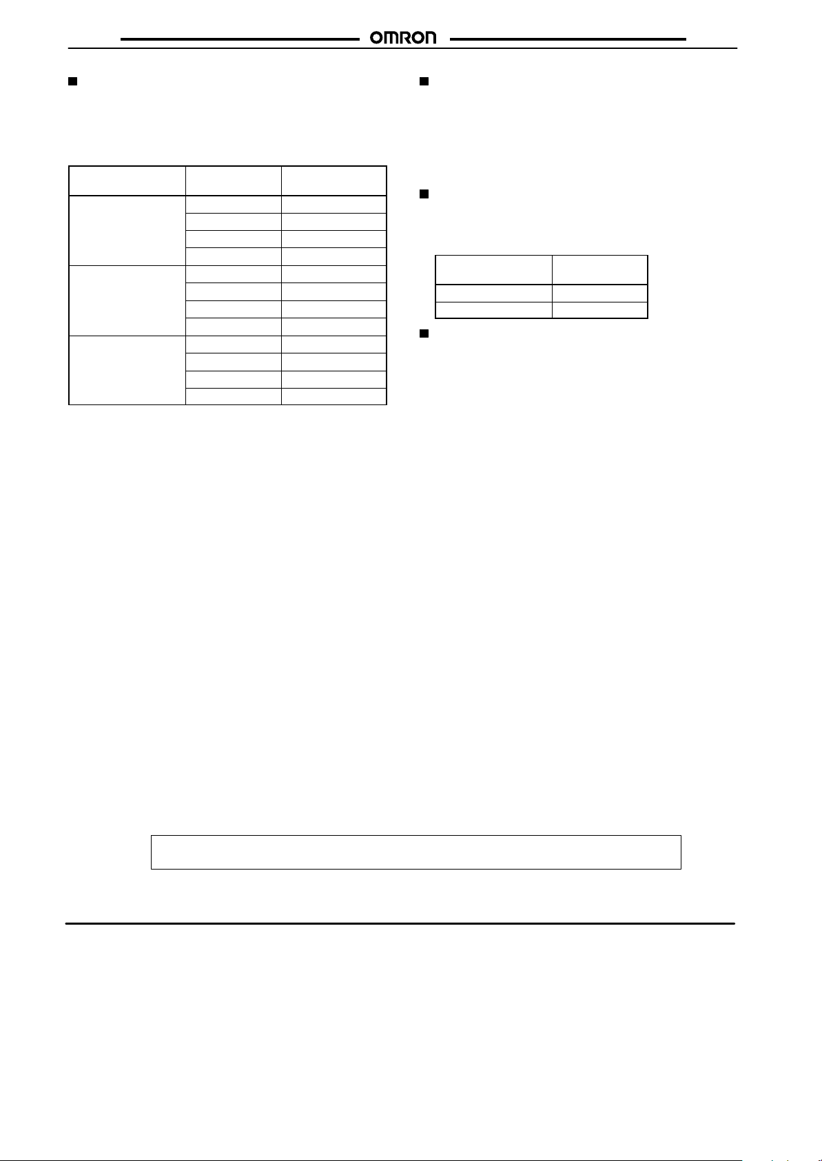
Output Delay
• The following table shows the delay from when the present value
passes the set value until the output is produced. (The delay is
the result of output control time, signal transmission time, relay
switching time, etc.)
Actual measurements in N and K modes.
Control output
Contact output 1, 2 30 Hz {cps} 18 to 24 ms
Transistor output 1, 2 30 Hz {cps} 13.5 to 20 ms
Batch outputs 30 Hz {cps} 13.6 to 20.2 ms
*The variation in delays is due to different modes and conditions.
For systems where the delay is a problem, take actual measurements under operating conditions.
Max. counting
speed
1 kHz {cps} 4.7 to 5.8 ms
5 kHz {cps} 4.4 to 5.4 ms
10 kHz {cps} 4.3 to 5.3 ms
1 kHz {cps} 0.59 to 0.81 ms
5 kHz {cps} 0.29 to 0.44 ms
10 kHz {cps} 0.24 to 0.36 ms
1 kHz {cps} 0.72 to 0.94 ms
5 kHz {cps} 0.42 to 0.57 ms
10 kHz {cps} 0.37 to 0.49 ms
Output delay*
Max. Count Speed of Batch Counter
• The maximum count speed of the batch counter is 1 kHz {cps}.
The batch counter counts the number of count-up times at the
last stage (i.e., the number of preset-value counts if the H7BR is
a one-stage model and the number of SET2 preset-value counts
if the H7BR is a two-stage model). An interval of 1 ms or more is
required before the batch counter counts up again after it has
counted up.
Response Delay Time for Resetting
(Transistor Output)
• Take the following output delays into consideration after the
reset signal input is turned ON and the output is turned OFF.
Minimum reset
signal width
1 ms 0.8 to 1.2 ms
20 ms 15 to 25 ms
Output delay
time
Other
• When the Counter is installed in a control box and tests are
conducted which may damage the Counter’s internal circuitry
(for example, a test measuring the maximum voltage difference
between the control circuit and metal components), remove the
Counter from the control box or short-circuit the terminals.
ALL DIMENSIONS SHOWN ARE IN MILLIMETERS.
To convert millimeters into inches, multiply by 0.03937. To convert grams into ounces, multiply by 0.03527.
Cat. No. M009-E1-01D
In the interest of product improvement, specifications are subject to change without notice.
OMRON Corporation
Industrial Automation Company
Industrial Control Components Division
Shiokoji Horikawa, Shimogyo-ku,
Kyoto, 600-8530 Japan
Tel: (81)75-344-7119/Fax: (81)75-344-7149
24
Printed in Japan
0103-0.5C (1190)
Page 25

Read and Understand This Catalog
Please read and understand this catalog before purchasing the products. Please consult your OMRON representative if you have any questions or
comments.
Warranty and Limitations of Liability
WARRANTY
OMRON's exclusive warrant y is that the products are free from defects in materials and workmanship for a period of one year (or other period if
specified) from date of sale by OMRON.
OMRON MAKES NO WARRANTY OR REPRESENTATION, EXPRESS OR IMPLIED, REGARDING NON-INFRINGEMENT, MERCHANTABILITY, OR
FITNESS FOR PARTICULAR PURPOSE OF THE PRODUCTS. ANY BUYER OR USER ACKNOWLEDGES THAT THE BUYER OR USER ALONE HAS
DETERMINED THAT THE PRODUCTS WILL SUITABLY MEET THE REQUIREMENTS OF THEIR INTENDED USE. OMRON DISCLAIMS ALL OTHER
WARRANTIES, EXPRESS OR IMPLIED.
LIMITATIONS OF LIABILITY
OMRON SHALL NOT BE RESPONSIBLE FOR SPECIAL, INDIRECT, OR CONSEQUENTIAL DAMAGES, LOSS OF PROFITS, OR COMMERCIAL
LOSS IN ANY WAY CONNECTED WITH THE PRODUCTS, WHETHER SUCH CLAIM IS BASED ON CONTRACT, WARRANT Y, NEGLIGENCE, OR
STRICT LIABILITY.
In no event shall responsibility of OMRON for any act exceed the individual price of the product on which liability is asserted.
IN NO EVENT SHALL OMRON BE RESPONSIBLE FOR WARR ANTY, REPAIR, OR OTHER CL AIMS REGARDING THE PRODUCTS UNLESS
OMRON'S ANALYSIS CONFIRMS THAT THE PRODUCTS WERE PROPERLY HANDLED, STORED, INSTALLED, AND MAINTAINED AND NOT
SUBJECT TO CONTAMINATION, ABUSE, MISUSE, OR INAPPROPRIATE MODIFICATION OR REPAIR.
Application Considerations
SUITABILITY FOR USE
OMRON shall not be responsible for conformity with any standards, codes, or regulations that apply to the combination of products in the customer's
application or use of the product.
At the customer's request, OMRON will provide applicable third party cer tification documents identifying ratings and limitations of use that apply to the
produc ts. This information by itself is not sufficient for a complete determination of the suitability of the products in combination with the end product,
machine, system, or other application or use.
The following are some examples of applications for which particular attention must be given. This is not intended to be an exhaustive list of all possible
uses of the products, nor is it intended to imply that the uses listed may be suitable for the products:
• Outdoor use, uses involving potential chemical contamination or electrical interference, or conditions or uses not described in this catalog.
• Nuclear energy control systems, combustion systems, railroad systems, aviation systems, medical equipment, amusement machines, vehicles, safety
equipment, and installations subject to separate industry or government regulations.
• Systems, machines, and equipment that could present a risk to life or proper ty.
Please know and observe all prohibitions of use applicable to the products.
NEVER USE THE PRODUCTS FOR AN APPLICATION INVOLVING SERIOUS RISK TO LIFE OR PROPERTY WITHOUT ENSURING THAT THE
SYSTEM AS A WHOLE HAS BEEN DESIGNED TO ADDRESS THE RISKS, AND THAT THE OMRON PRODUCT IS PROPERLY RATED AND
INSTALLED FOR THE INTENDED USE WITHIN THE OVERALL EQUIPMENT OR SYSTEM.
Disclaimers
CHANGE IN SPECIFICATIONS
Product specifications and accessories may be changed at any time based on improvements and other reasons.
It is our practice to change model numbers when published ratings or features are changed, or when significant construction changes are made.
However, some specifications of the product may be changed without any notice. When in doubt, special model numbers may be assigned to fix
or establish key specifications for your application on your request. Please consult with your OMRON representative at any time to confirm actual
specifications of purchased product.
DIMENSIONS AND WEIGHTS
Dimensions and weights are nominal and are not to be used for manufacturing purposes, even when tolerances are shown.
ERRORS AND OMISSIONS
The information in this catalog has been carefully checked and is believed to be accurate; however, no responsibilit y is assumed for clerical,
typographical, or proofreading errors, or omissions.
PERFORMANCE DATA
Performance data given in this catalog is provided as a guide for the user in determining suitability and does not constitute a warranty. It may represent
the result of OMRON’s test conditions, and the users must correlate it to actual application requirements. Actual performance is subject to the OMRON
Warranty and Limitations of Liability.
PROGRAMMABLE PRODUCTS
OMRON shall not be responsible for the user's programming of a programmable product, or any consequence thereof.
COPYRIGHT AND COPY PERMISSION
This catalog shall not be copied for sales or promotions without permission.
This catalog is protected by copyright and is intended solely for use in conjunction with the product. Please notify us before copying or reproducing this
catalog in any manner, for any other purpose. If copying or transmitting this catalog to another, please copy or transmit it in its entirety.
Cat. No. M009-E1-01D
OMRON Corporation
Industrial Automation Company
http://www.ia.omron.com/
In the interest of product improvement, specifications are subject to change without notice.
(c)Copyright OMRON Corporation 2007 All Rights Reserved.
2007.3
 Loading...