

Omron H7BX DATASHEET
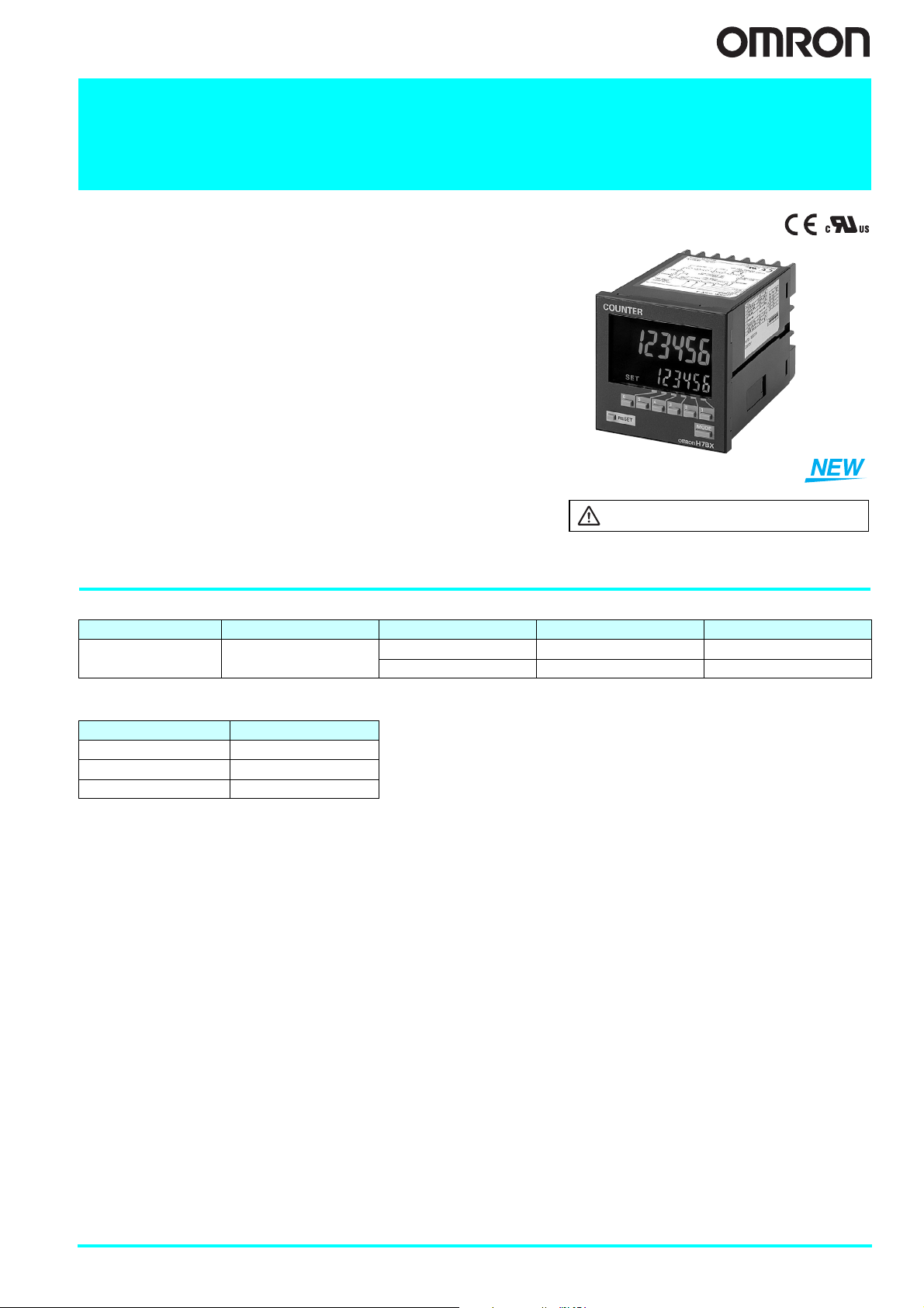
Multifunction Counter
H7BX
DIN 72×72 mm Multifunction Counter with a Bright,
Easy-to-view, Negative Transmissive LCD.
• Highly visible display with backlit transmissive LCD.
• Selectable display color (red/green) enables checking output status at a
distance.
• Easy operation with a key for each digit.
• Perform all basic settings with a DIP switch.
• Provides a total and preset counter, batch counter, dual counter, and
tachometer (See note.).
• Wide range of inputs accepted for NPN/PNP inputs (multi-inputs) and 2wire DC sensors.
• Complies with UL, CSA, and CE marking.
• Degree of protection: IP54 equivalent (front section only).
Note: The functions that can be selected depend on the model.
Be sure to read Safety Precautions on page 25.
Ordering Information
■ List of Models
External power supply Output type Supply voltage 1-stage 2-stage
12 VDC
Contact and
NPN transistor output
■ Accessories (Order Separately)
Name Model
Soft Cover Y92A-72F1
Hard Cover Y92A-72
Terminal Cover (See note.) Y92A-72T
Note: Supplied with the H7BX.
100 to 240 VAC H7BX-A H7BX-AW
24 VAC/12 to 24 VDC H7BX-AD1 H7BX-AWD1
Multifunction Counter H7BX 1
Specifications
■ Ratings
Item Model H7BX-A/AD1 H7BX-AW/AWD1
Type Preset counter Preset counter/tachometer
Supported configurations
Power supply voltage
(See note 2.)
Ratings
Mounting method Flush mounting
External connections Screw terminals
Degree of protection IP54 (front section only)
Input signals CP1, CP2, reset 1, reset 2, key protection
Counter
Tachometer
Prescaling function Yes (0.001 to 99.999)
Decimal point adjustment Yes (rightmost 3 digits)
Sensor waiting time 290 ms max. (Control output is turned OFF and no input is accepted during sensor waiting time.)
Key protection input
Input method
(except key protection input)
External power supply 12 VDC (±10%), 100 mA (For details, refer to External Power Supply on page 26.)
Control output
Display (See note 3.)
Digits
Memory backup EEPROM (Overwrites: 100,000 min.), Data storage: 10 years min.
Ambient operating temperature −10 to 55°C (with no icing)
Ambient storage temperature −25 to 65°C (with no icing)
Ambient operating humidity 25 to 85°C (with no condensation)
Case color Black (N1.5)
Accessories Two flush-mounting adapters, terminal cover
Note 1. The total and preset counter functions as a 1-stage preset counter and total counter.
Operating voltage range 85% to 110% of rated supply voltage (90% to 110% at 12 VDC)
Power consumption
Max. counting speed 30 Hz or 5 kHz (selectable, ON/OFF ratio 1:1), setting for both CP1 and CP2
Input modes Increment, decrement, command (UP/DOWN A), individual (UP/DOWN B), quadrature (UP/DOWN C)
Output modes N, F, C, R, K-1, P, Q, A, K-2, D, L N, F, C, R, K-1, P, Q, A, K-2, D, L, H
One-shot output time 0.01 to 99.99 s
Reset input
Pulse measurement
method
Max. counting speed --- 30 Hz or 10 kHz (selectable)
Measuring ranges ---
Measuring accuracy --- ±0.1% FS ±1 digit max. (at 23 ±5°C)
Output modes --- Upper and lower limits, area, upper limit, lower limit
Auto-zero time --- 0.1 to 99.9 s
Startup time --- 0.0 to 99.9 s
Average processing --- OFF/2/4/8 times
2. Do not use an inverter output for the power supply.
3. Displayed only when the power is ON. Not displayed when the power is OFF.
1-stage preset counter, total and preset counter (See note
1.) (selectable)
• 100 to 240 VAC (50/60 Hz)
• 24 VAC (50/60 Hz)/12 to 24 VDC (ripple 20% max.)
H7BX-A/AW: 9.6 VA max. (100 to 240 VAC)
H7BX-AD1/AWD1: 8 VA max. (24 VAC), 5.3 W max. (12 to 24 VDC)
External reset (minimum reset input signal width: 1 ms or 20 ms selectable), manual reset, and automatic reset (internal
according to C, R, P, and Q mode operation)
--- Periodic measurement (Sampling period: 200 ms)
Response speed: Approx. 1 s
No-voltage NPN input (fixed)
Short-circuit (ON) impedance: 1 kΩ max. (Leakage current at 0 Ω: Approx. 12 mA)
Short-circuit (ON) residual voltage: 3 V max.
Open (OFF) impedance: 100 kΩ min.
No-voltage NPN input or voltage PNP input (selectable)
No-voltage input
Short-circuit (ON) impedance: 1 kΩ max. (Leakage current at 0 Ω: Approx. 12 mA)
Short-circuit (ON) residual voltage: 3 V max.
Open (OFF) impedance: 100 kΩ min.
Voltage input
High level: 4.5 to 30 VDC
Low level: 0 to 2 VDC
Input resistance: Approx. 4.7 kΩ
Contact output: 3 A at 250 VDC/30 VDC, resistive load (cosφ = 1)
Minimum applied load: 10 mA at 5 VDC (Failure level: P, reference value)
Transistor output: 100 mA max. at 30 VDC max.
Residual voltage: 1.5 VDC max. (approx. 1 V)
Leakage current: 0.1 mA max.
Backlit 7-segment negative transmissive LCD
Character Heights
PV: 13.5 mm (red/green)
SV: 9 mm (green)
6 digits
−99,999 to 999,999 (5 digits negative and 6 digits positive)
1-stage preset counter, 2-stage preset counter, total and
preset counter (See note 1.), batch counter, dual counter,
tachometer (selectable)
30 Hz: 0.01 to 30.00 Hz
10 kHz: 0.01 Hz to 10 kHz
6 digits
Counter: −99,999 to 999,999 (5 digits negative and 6 digits
positive)
Tachometer: 0 to 999,999 (6 digits)
Two flush-mounting adapters, terminal cover, DIP switch
setting stickers
2 Multifunction Counter H7BX

■ Characteristics
(A)
oad curre
)
Insulation resistance
Dielectric
strength
Impulse withstand voltage
Noise immunity
Static immunity
Vibration resistance
Shock resistance
Life expectancy
Weight Approx. 250 g
Note: Check the electrical life expectancy curve.
100 MΩ min. (at 500 VDC) between current-carrying terminal and exposed noncurrent-carrying metal parts, and between non-continuous contacts
Between current-carrying metal parts and non-current-carrying metal parts:
2,000 VAC, 50/60 Hz for 1 min
Between power supply and input circuit: 2,000 VAC, 50/60 Hz for 1 min (for models
other than the H7BX-A@D1)
1,000 VAC, 50/60 Hz for 1 min (H7BX-A@D1)
Between control output, power supply, and input circuit: 2,000 VAC, 50/60 Hz for 1 min
Between non-continuous contacts: 1,000 VAC, 50/60 Hz for 1 min
Between power terminals: 3.0 kV (1.0 kV for 24 VAC/12 to 24 VDC models)
Between current-carrying terminal and exposed non-current-carrying metal parts:
4.5 kV (1.5 kV for 24 VAC/12 to 24 VDC models)
Between power terminals: ±1.5 kV
Between input terminals: ±600 V
Square-wave noise by noise simulator (Pulse width: 100 ns/1 µs, 1-ns rise)
Malfunction: 8 kV
Destruction: 15 kV
Destruction: 10 to 55 Hz, 0.75-mm single amplitude for 4 cycles each in 3 directions (8
min/cycle)
Malfunction: 10 to 55 Hz, 0.50-mm single amplitude for 4 cycles each in 3 directions (8
min/cycle)
Destruction: 294 m/s2 3 times each in 6 directions
Malfunction: 98 m/s
2
3 times each in 6 directions
Mechanical: 10,000,000 operations min.
Electrical: 100,000 operations min. (3 A at 250 VAC/30 VDC, resistive load) (See
note.)
● Electrical Life Expectancy
(Reference Values)
Resistive Load
)
3
1,000
700
500
300
No. of operations (×10
100
70
50
01 2 34
30 VDC (cosφ=1)
250 VAC (cosφ=1)
Inductive Load
)
3
1,000
700
500
300
No. of operations (×10
30 VDC (L/R=7 ms)
Load current
■ Applicable Standards
Approved
safety
standards
EMC
cURus: UL 508, CSA C22.2 No. 14
EN 61010-1 (IEC 61010-1): Pollution degree 2/overvoltage category II;
EN 61326; VDE 0106 Part 100
(EMI) EN 61326
Emission Enclosure: EN 55011 Group 1 class A
Emission AC mains: EN 55011 Group 1 class A
(EMS) EN 61326
Immunity ESD: EN 61000-4-2: 4 kV contact discharge;
Immunity RF-interference: EN 61000-4-3:10 V/m (Amplitude-modulated,
Immunity Conducted Disturbance: EN 61000-4-6: 3 V (0.15 to 80 MHz)
Immunity Burst: EN 61000-4-4: 2 kV power-line;
Immunity Surge: EN 61000-4-5: 1 kV line to lines (power and output lines
Immunity Voltage Dip/Interruption:EN 61000-4-11: 0.5 cycle, 100% (rated voltage)
8 kV air discharge
80 MHz to 1 GHz);
10 V/m (Pulse-modulated,
900 MHz ±5MHz)
1 kV I/O signal-line
(relay outputs));
2 kV line to ground (power and output lines
(relay outputs))
100
250 VAC (cosφ=0.4)
70
50
01 2 34
L
nt (A
A current of 0.15 A max. can be switched at
125 VDC (cos
φ
= 1) and current of 0.1 A max. can
be switched with L/R = 7 m/s. In both cases, a life of
100,000 operations can be expected.
Multifunction Counter H7BX 3
■ I/O Functions
● Using as a Counter (See note 1.)
(1) All Modes Except for Dual Counter Mode
• Reads count signals.
• Increment, decrement, up/down (command, individual, or quadrature) inputs
CP1, CP2
Inputs
Reset or
Reset 1
Total Reset
or Reset 2
Outputs OUT1, 2
Note 1. Refer to pages 14 to 17 for information on the operation of input and output functions.
2. In increment mode or increment/decrement mode, the present value returns to 0; in decrement
mode, the present value returns to the set value with 1-stage models, and returns to set value 2 with
2-stage models.
3. The reset indicator will not be lit when the total reset or reset 2 input is ON.
Function Reset operation
1-stage/2-stage preset counter Does not operate (Not used).
Total and preset counter
Batch counter
Dual counter
can be used.
(2) Dual Counter Mode
• Reads CP1 count signals on CP1 input and CP2 count signals on CP2 input.
• Increment signals can be used.
(1) All Modes Except for Dual Counter Mode
• Resets present value and outputs (OUT2 when using the batch counter). (See
note 2.)
• Counting cannot be performed while resetting or when reset 1 input is ON.
• The reset indicator is lit while the reset input is ON.
(2) Dual Counter Mode
• Resets the CP1 present value to 0.
• Counting the CP1 input cannot be performed while the reset 1 input is ON.
• The reset indicator is lit while the reset 1 input is ON.
The reset operation depends on the selected function. (See note 3.)
When the corresponding set value is reached, signals are output according to the
designated output mode.
• Resets the total count value.
• Holds the total count value at 0 while the total reset input is ON.
• Resets the batch count value and batch output (OUT1).
• Holds the batch count value at 0 while the reset 2 input is ON.
• Resets the CP2 present value.
• Counting for CP2 input is disabled while the reset 2 input is ON.
● Using as a Tachometer
CP1,
CP2
Inputs
Reset 1,
Reset 2
Outputs OUT1, 2
Reads counting signals.
(CP2 input is not
available.)
• Holds the measurement
value and outputs.
(Reset 2 input is not
available.)
• The reset indicator is lit
during hold.
Outputs signals according
to the specified output
mode when a set value is
reached.
● Using as a Counter or
Tachometer
• Prohibits using the keys
Key protection
input
Note: For details, refer to page 24.
on the front panel.
• Set the key protection
level in function selection
mode.
4 Multifunction Counter H7BX
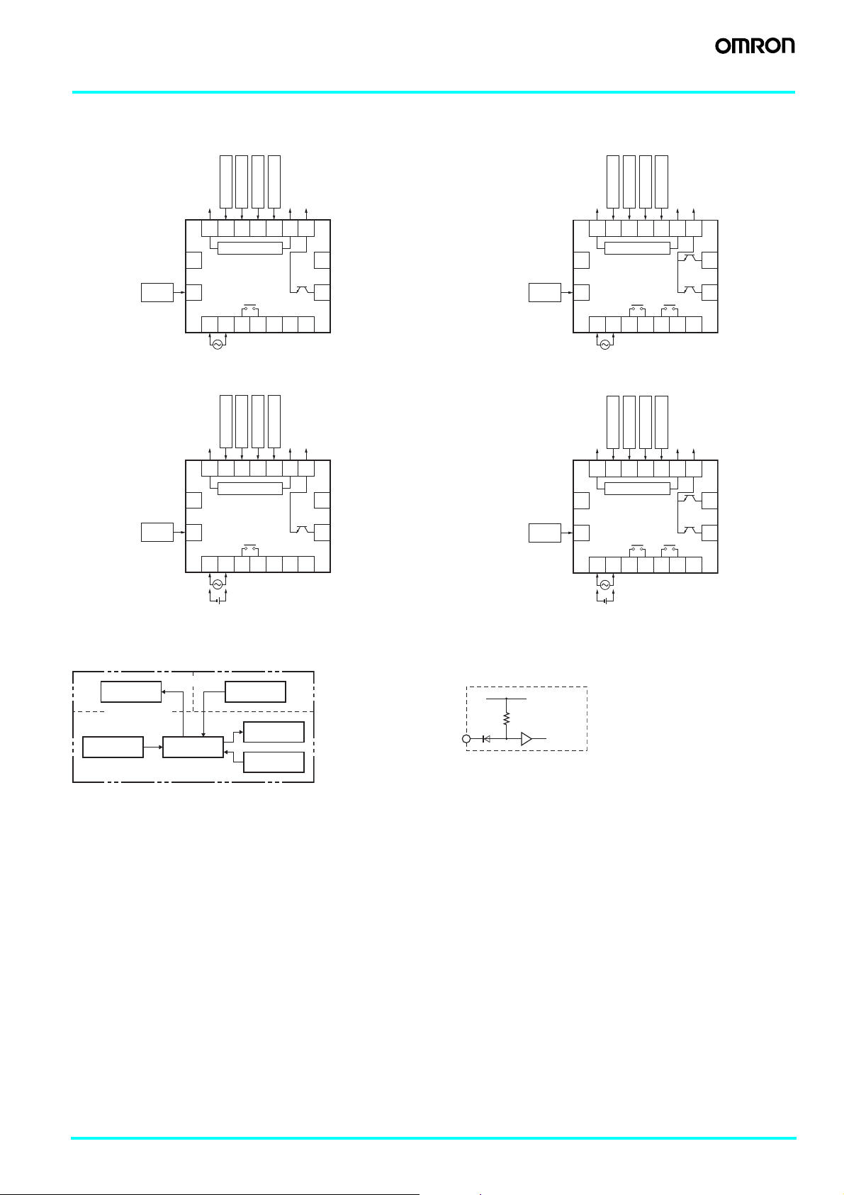
Connections
■ Terminal Arrangement
Confirm that the power supply meets specifications before using the H7BX.
H7BX-A H7BX-AW
CP2
CP1
0 V
Reset 1
Reset 2
12 VDC
Output COM
0 V
Reset 1
CP2
CP1
Reset 2
Output COM
12 VDC
8 9 10 11 12 13 14
(−) (+)
Unused.
Key
protection
External power supply
15
16
OUT
1234567
Unused.
OUT
Unused.
Unused.
17
18
Unused.
H7BX-AD1 H7BX-AWD1
CP1
CP2
OUT
Reset 2
Unused.
12 VDC
OUT
Unused.
Output COM
Unused.Unused.
17
18
Unused.
Reset 1
0 V
8 9 10 11 12 13 14
(−) (+)
External power supply
15
Key
protection
16
1234567
(−) (+)
Note: Do not use the unused terminals for relay connections.
Unused.
Key
protection
Unused.
Key
protection
8 9 10 11 12 13 14
(−) (+)
External power supply
15
16
15
16
OUT2 OUT1
1234567
CP2
CP1
Reset 1
0 V
8 9 10 11 12 13 14
(−) (+)
External power supply
OUT2 OUT1
1234567
(−) (+)
OUT1
OUT2
Reset 2
OUT1
OUT2
Unused.
12 VDC
Output COM
Unused.
17
18
17
18
■ Block Diagram ■ Input Circuits
● CP1, CP2, Reset/Reset 1, and Total Reset/Reset 2 Input
+14 V
1 kΩ
IN
Internal
circuit
Output circuit
(Basic insulation)
Input circuit
(Basic insulation)
Internal control
circuit
Power supply
circuit
Display circuit
Key switch
circuit
Note: The circuit shown above is for
no-voltage input (NPN input).
Multifunction Counter H7BX 5
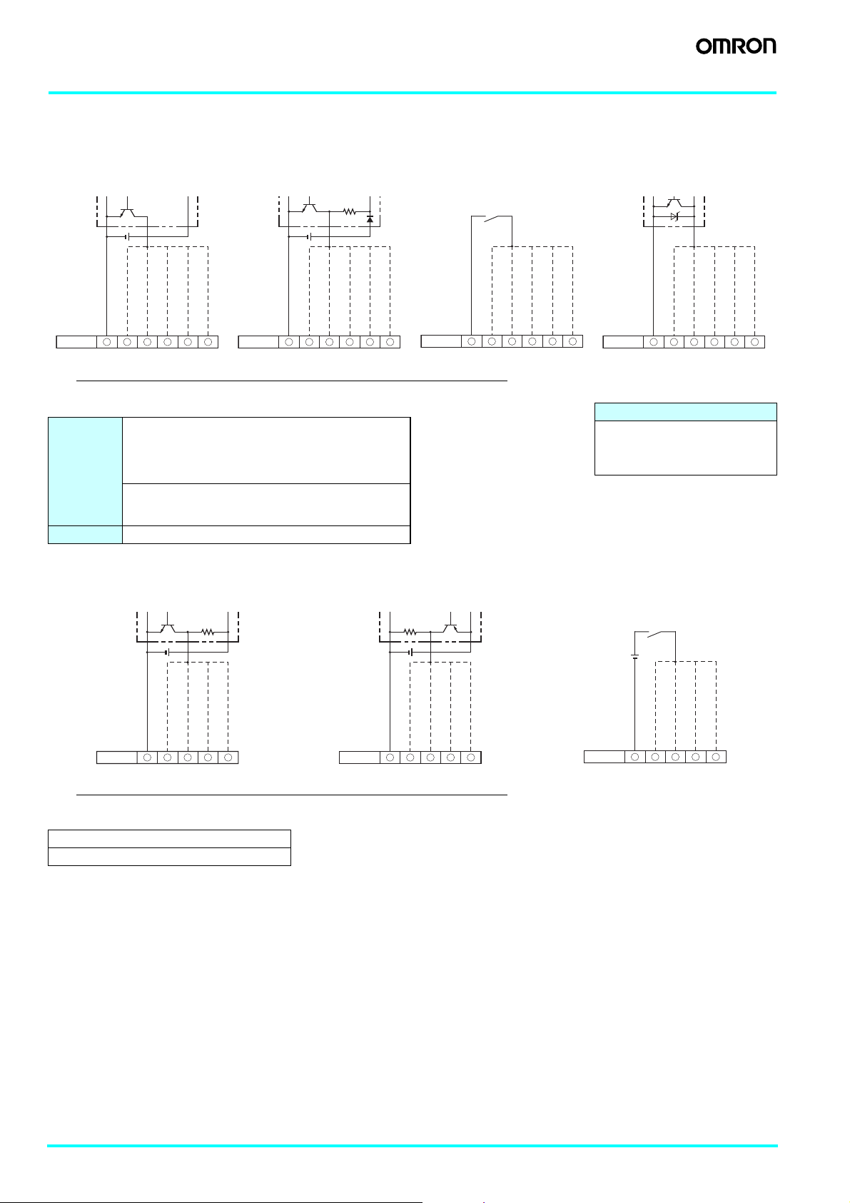
■ Input Connections
A no-voltage input (short-circuit or open) or voltage input can be selected for each input. (The key protection input is always a no-voltage
input (NPN input)).
● No-voltage Inputs (NPN Inputs)
Open Collector Voltage Output Contact Input DC Two-wire Sensor
PLC
or sensor
0-V input
CP2 input
CP1 input
Reset/reset 1 input
8 9
Terminal No.
Operates when the transistor turns ON.
10 11 12 16
Total reset/reset 2 input
Sensor
0-V input
Key protection input
Terminal No.
Operates when the transistor turns ON.
Reset/reset 1 input
8 9
CP2 input
CP1 input
10 11 12 16
Total reset/reset 2 input
0-V input
Key protection input
Terminal No.
Operates when the contact turns ON.
8 9
CP2 input
CP1 input
Reset/reset 1 input
10 11 12 16
Key protection input
Total reset/reset 2 input
Note: When the H7BX is used as a tachometer, the CP2 input and total reset/reset 2 input are not used.
No-voltage Input Signal Levels
Short-circuit level
Transistor ON
• Residual voltage: 3 V max.
No-contact
input
• Impedance when ON: 1 kΩ max.
(The leakage current is 5 to 12 mA when the impedance is 0 Ω.)
Open level
Transistor OFF
• Impedance when OFF: 100 kΩ min.
Contact input Use contact which can adequately switch 5 mA at 10 V.
Note: Use a DC power supply of 30 V max.
● Voltage Inputs (PNP Inputs)
No-contact Input (NPN Transistor) No-contact Input (PNP Transistor) Contact Input
0-V input
CP2 input
CP1 input
Reset/reset 1 input
8 9
Terminal No.
Operates when the transistor turns ON.
10 11 12 16
Applicable Two-wire Sensors
• Leakage current: 1.5 mA max.
• Switching capacity: 5 mA min.
• Residual voltage: 3 VDC max.
• Operating voltage: 10 VDC
Key protection input
Total reset/reset 2 input
Sensor
0-V input
CP2 input
CP1 input
Reset/reset 1 input
Terminal No.
Operates when the transistor turns OFF.
8 9
10 11 12
Total reset/reset 2 input
Sensor
0-V input
CP2 input
CP1 input
Reset/reset 1 input
8 9
Terminal No.
Operates when the transistor turns ON.
10 11 12
Total reset/reset 2 input
Note: When the H7BX is used as a tachometer, the CP2 input and total reset/reset 2 input are not used.
Voltage Input Signal Levels
High level (Input ON): 4.5 to 30 VDC
Low level (Input OFF): 0 to 2 VDC
Note 1. Use a DC power supply of 30 V max.
2. Input resistance: Approx. 4.7 kΩ
0-V input
CP2 input
CP1 input
Reset/reset 1 input
8 9
Terminal No.
Operates when the contact turns ON.
10 11 12
Total reset/reset 2 input
6 Multifunction Counter H7BX
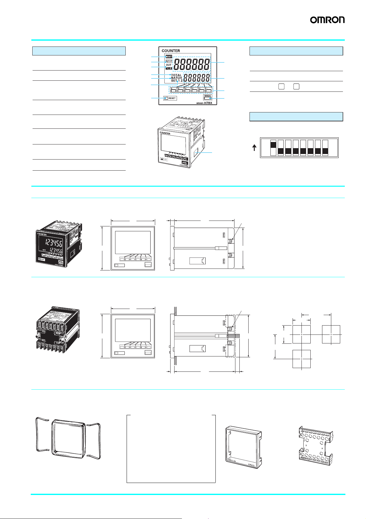
Nomenclature
Indicators
A Reset Indicator (Orange)
Lit when the reset input (1) or reset key is ON.
B Key Protection Indicator (Orange)
C Control Output Indicator (Orange)
OUT: One stage
OUT1, OUT2: Two stages
A
B
D
C
F
G
E
H
K
J
I
I Mode Key
Used to switch mode and setting items.
J Reset Key
K Up Keys:
Operation Keys
1 6
to
D Present Value (Main Display)
Character height: 13.5 mm (Red/green selectable)
A
IN
H
C
E Set Value (Sub-display)
Character height: 9 mm (Green)
F Total Count Indicator (Green)
Lit when the total count value is displayed.
G Batch Indicator (Green)
Lit when the batch count value is displayed.
H
Set Value 1 and 2 Stage Indicators
(Green)
IN
X
DE
X
A
X
M
X
X
X
.
o
N
t
o
L
n
o
i
t
a
r
o
p
r
o
C
N
O
R
M
O
A
X
R
B
E
7
T
H
N
U
O
C
L DIP Switch
ON
L
OFF
Switches
1
2345678
Dimensions (Unit: mm)
■ Counter
● Counter
H7BX-A@@
72
6
100
M3.5 terminal screw
(effective length: 6 mm)
72
● Dimensions with Flush Mounting Adapter
H7BX-A@@
(The flush mounting adapter is supplied with the H7BX.)
72
72
6
■ Accessories (Order Separately)
● Soft Cover
Y92A-72F1
Note: Depending on the operating environment,
the condition of resin parts may
deteriorate, and may shrink or harden.
Therefore, it is recommended that resin
parts are replaced regularly.
Product Protection for Use in
Environments Subject to Water or Oil
The panel surface has a protective
structure so that the internal circuits will
not be adversely affected if drops of water
penetrate the gaps between the keys. If,
however, there is a possibility of water or
oil being present on the operator's hands,
mount the optional Soft Cover.
The Soft Cover ensures protection
equivalent to IP54. Do not, however, use
the H7BX in locations where it would come
into direct contact with oil.
Panel
102
67.6 × 67.6
M3.5 terminal screw
(effective length: 6 mm)
69 × 69
5 + panel thickness
● Hard
Cover
Y92A-72
Note: M3.5 terminal screws
(effective length: 6 mm).
Panel Cutouts
Panel cutouts are as shown below
(according to DIN 43700).
100 min.
+0.7
68
−0
+0.7
68
−0
82 min.
Note: The mounting panel thickness
must be 1 to 5 mm.
● Terminal Cover (See note.)
Y92A-72T
(VDE0106/T100)
Note: Supplied with the
H7BX.
Multifunction Counter H7BX 7
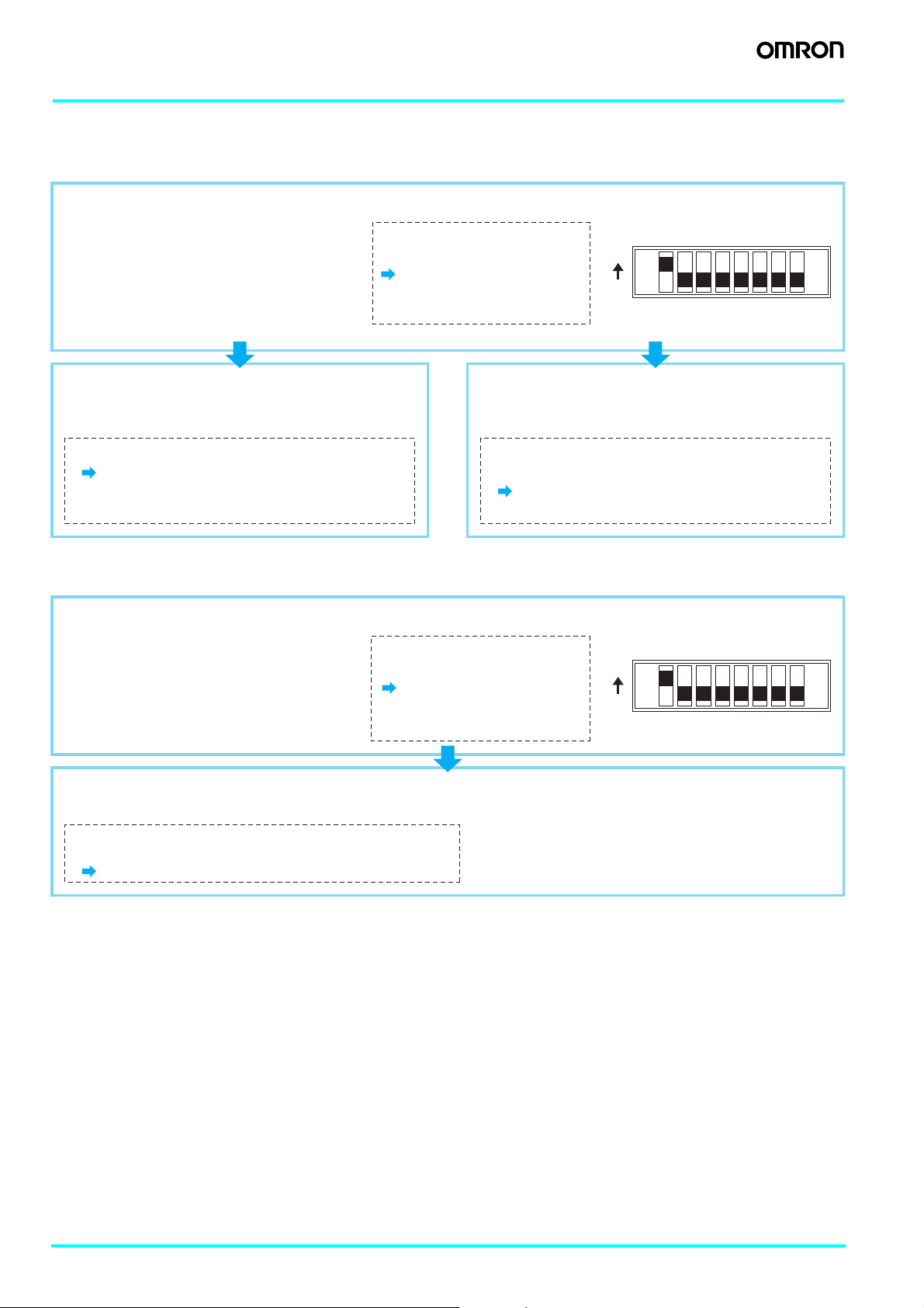
Operating Procedures
■ Setting Procedure Guide
Settings for Counter Operation
(1-stage/2-stage Counter, Total and Preset Counter, Batch Counter, Dual Counter)
● Using Basic Settings Only
Basic Settings
• Counting speed (30 Hz, 5 kHz)
• Input mode (UP, DOWN)
• Output mode (N, F, C, K-1)
• One-shot output time (0.5 s, 0.05 s)
• Reset input signal width (20 ms, 1 ms)
• NPN/PNP input mode (NPN, PNP)
The settings can be made
easily with the DIP switch.
For details on the setting
methods, refer to page 9.
ON
OFF
1
2345678
● Using Input Modes Not Given Above (Up/Down A,
Up/Down B, Up/Down C) , Output Modes
(R/P/Q/A/K-2/D/L/H), or (OUT2) Output Time
Set all functions with the operation keys.
For details on the setting methods,
refer to page 10.
●
Performing Advanced Settings: Dual Count Calculating
Mode, Output 1 Time, Decimal Point Position, Prescale
Value, Display Color, or Key Protect Level
Settings other than the basic functions above
can be performed with the operation keys.
For details on the setting methods,
refer to page 10.
Note: The default setting is for a 1-stage preset counter. (For models with a 2-stage setting, the default is a 2-stage preset counter.)
Setting for Tachometer Operation
(H7BX-AW@ only)
● Using Basic Settings Only
Basic Settings
• Counting speed (30 Hz, 10 kHz)
• Output mode (HI-LO, AREA, HI-HI, LO-LO)
• Average processing (OFF, 2, 4, 8 times)
• NPN/PNP input mode (NPN, PNP)
The settings can be made
easily with the DIP switch.
For details on the setting
methods, refer to page 19.
ON
OFF
1
2345678
● Performing Advanced Settings: Decimal Point Position, Prescale Value, Auto-zero Time, Startup Time,
Display Color, or Key Protect Level
Settings other than the basic functions above can be
performed with the operation keys.
For details on the setting methods, refer to page 20.
Note: The default setting is for a 2-stage preset counter.
8 Multifunction Counter H7BX
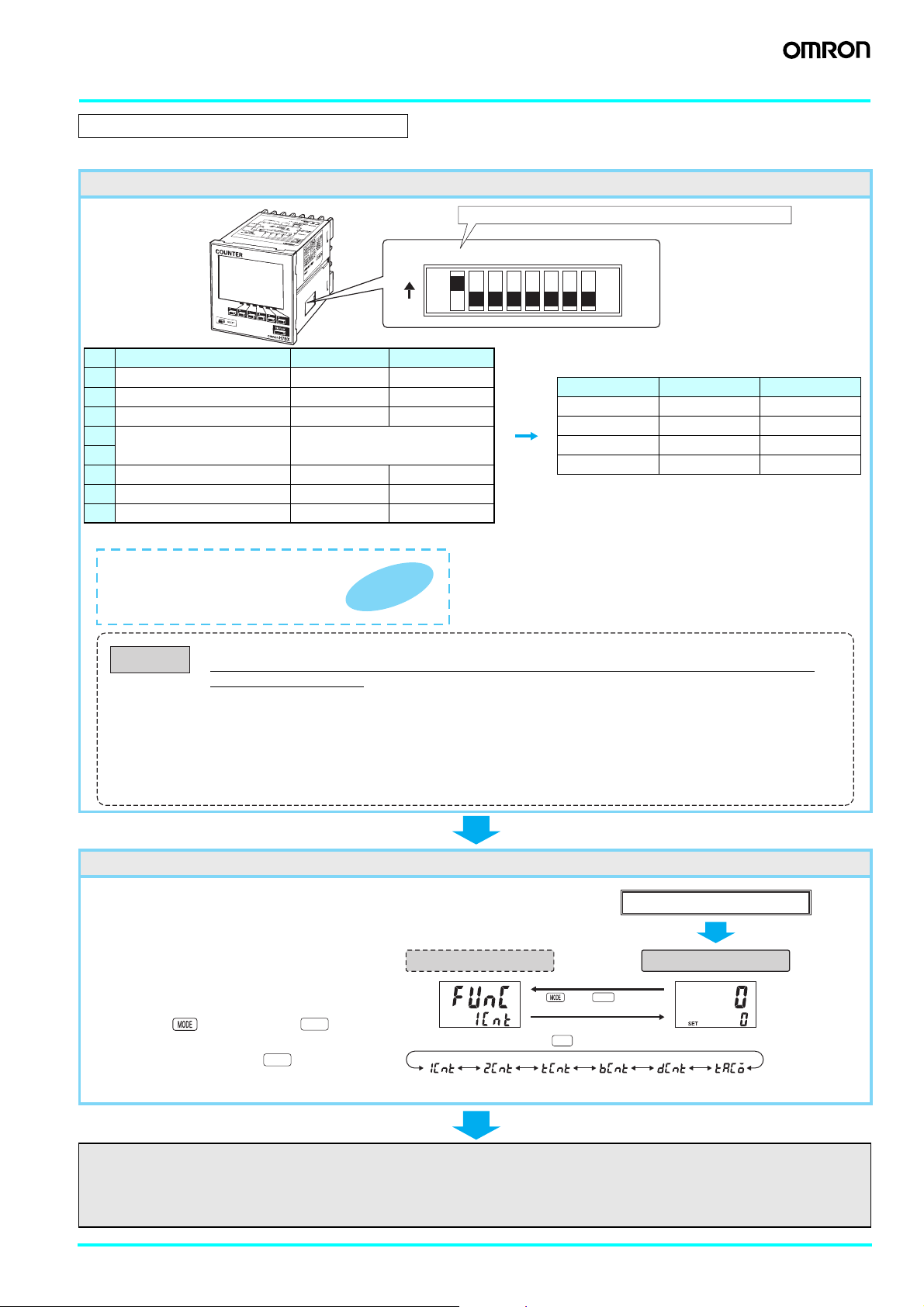
Operating Procedures (Counter Function)
■ Settings for Basic Operations
Settings for basic functions can be performed with just the DIP switch.
A
N
I
H
C
IN
X
E
D
X
A
X
M
X
X
X
o.
N
t
o
L
n
o
ti
a
or
p
r
Co
N
O
R
M
O
A
X
B
ER
7
T
H
N
U
CO
ON
OFF
Item OFF ON
1 DIP switch settings enable/disable Disabled Enabled
2 Counting speed 30 Hz 5 kHz
3 Input mode UP (increment) DOWN (decrement)
4
Output mode Refer to the table on the right.
5
6 One-shot output time (See note.) 0.5 s 0.05 s
7 Reset input signal width 20 ms 1 ms
8 NPN/PNP input mode NPN (no-voltage) PNP (voltage)
Note: All the pins are factory-set to OFF.
The ON/OFF status of the DIP switch pins
can be confirmed using the front display.
For details, refer to page 23.
Convenient
Function
Be sure to turn ON pin 1 when using the DIP switch.
1
2345678
Pin 4 Pin 5 Output mode
OFF OFF N
ON OFF F
OFF ON C
ON ON K-1
Caution
• Always turn OFF the power supply before changing the DIP switch settings.
• Always turn ON pin 1 when performing settings with the DIP switch. Performing settings with the DIP switch is
disabled when pin 1 is OFF.
• DIP switch setting changes will be updated when the power is turned ON. Perform the settings before performing
installation and supplying power.
• Properly set the DIP switch to match the item being counted (or measured) and use the DIP switch monitor for
confirmation.
• Use the keys on the front panel to perform all settings for input modes, output modes, and output times that cannot
be set with the DIP switch. For details on the setting methods, refer to page 10.
When performing these settings, always turn OFF pin 1(DIP switch setting) (disabled).
Using the H7BX as a Total and Preset Counter, Batch Counter, or Dual Counter
The default setting is for a 1-stage preset
counter. (For models with a 2-stage setting,
the default is for a 2-stage preset counter.)
To make changes, use the procedure shown
on the right. For details, refer to page 23.
Up 1
Up
Hold down the Key and press the Key
Up 1
for at least 1 s.
The mode will not change if the Key is
Up 1
pressed first.
Configuration
selection
Key + Key for at
least 1 s (See note.)
Select the configuration using the Key. (The configurations that can be selected depend on the model.)
counter)
(2-stage preset
counter)
(Total and
preset counter)
Note: This includes using a model with a 2-stage
setting as a 1-stage preset counter.
After setting the DIP switch for basic operations, advanced functions (see note) can be added using the operation keys. For details,
refer to page 10.
Power ON
Run modeConfiguration selection mode
(Tachometer)(Dual counter)(Batch counter)(1-stage preset
Note: Advanced functions consist of dual count calculating mode, output 1 time, decimal point position, prescale value,
display color, and key protect level.
Multifunction Counter H7BX 9
 Loading...