

Omron H5S-WB2, H5S-WB2D, H5S-WFB2, H5S-WFB2D, H5S-YB2-X Datasheet
...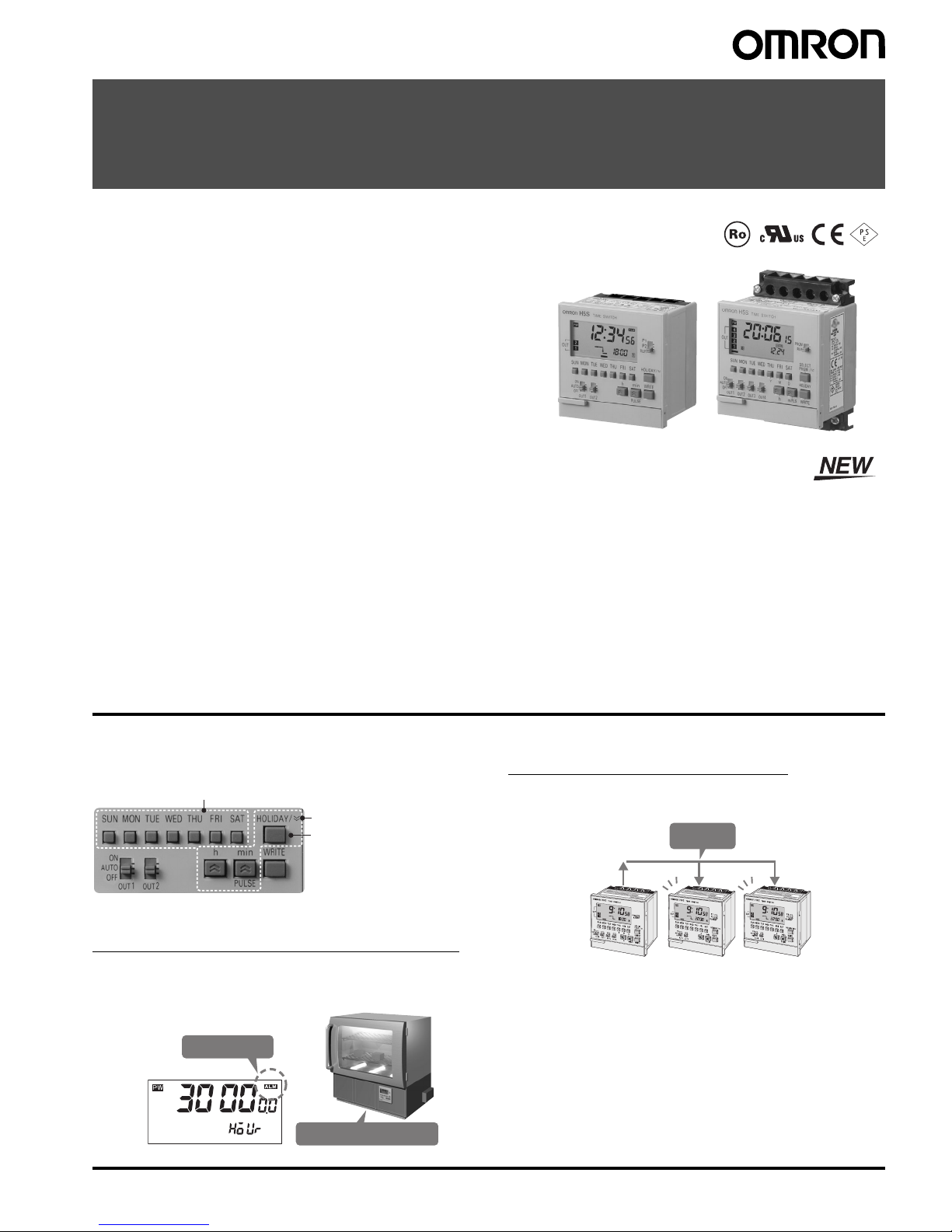
Digital Time Switch H5S 1
Digital Time Switch
H5S
Easier, More Convenient Time Switches, with
New 4-circuit Output and Yearly Models in
Addition to 2-circuit Weekly Models
• Independent Day Keys provide easier operation.
• Temporary holiday setting function makes it easy to turn OFF output
for holidays and non-operating days.
• Settings can be made even with the Time Switch turned OFF.
• Test mode enables easy program checking.
• Complies with EMC Directives, UL/CSA, and other safety standards.
• Includes summer time (DST) adjustment.
Yearly models also offer automatic switching to DST.
• Set value can be changed both upward and downward for speedier
setting.
• Integrated temperature compensation circuit helps keep accurate
time over a wide temperature range. (See note 1.)
• Includes time counter and total counter functions with alarm indicator.
(See note 2.)
• Bank function allows program switching by an external input. (See
note 3.)
• New 4-circuit output models with a compact, 72 × 72-mm DIN size
added to the series.
Note: 1. Available only on yearly models.
2. Available only on 2-circuit models.
3. Available only on weekly models.
Features
Easier and More Convenient to Use
■ Simple Setting
■ Convenient Functions
Time Counter/Total Counter Functions (See note.)
This function makes it possible to monitor the total time that a load
has been applied, or the total number of operating cycles. It allows
the Time Switch to be used for managing maintenance.
Time Adjustment Function (See note.)
The time can be set to 00 min 00 s by using an external input. The
times on multiple Time Switches can also be easily synchronized.
Note: Equipped on 2-circuit models.
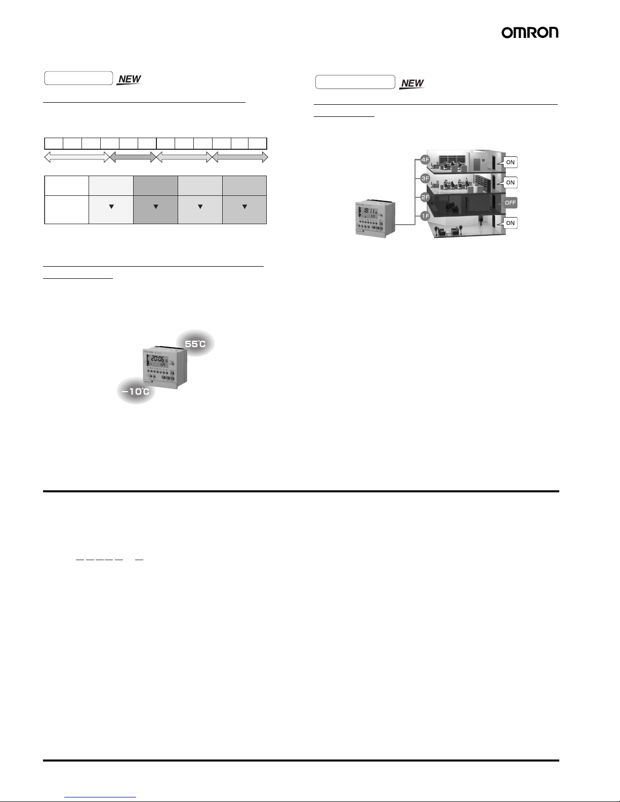
Independent Day Keys make setting easy.
Up/down set value changing
for speedy setting.
Temporary holidays
(non-operating days)
are also easy to set.
Weekly models: Specify the day.
Ye a r l
y
models: Specify the date.
With alarm indicator
Shows total lamp ON time
Synchronized!
Master
Slave
Slave
2 Digital Time Switch H5S
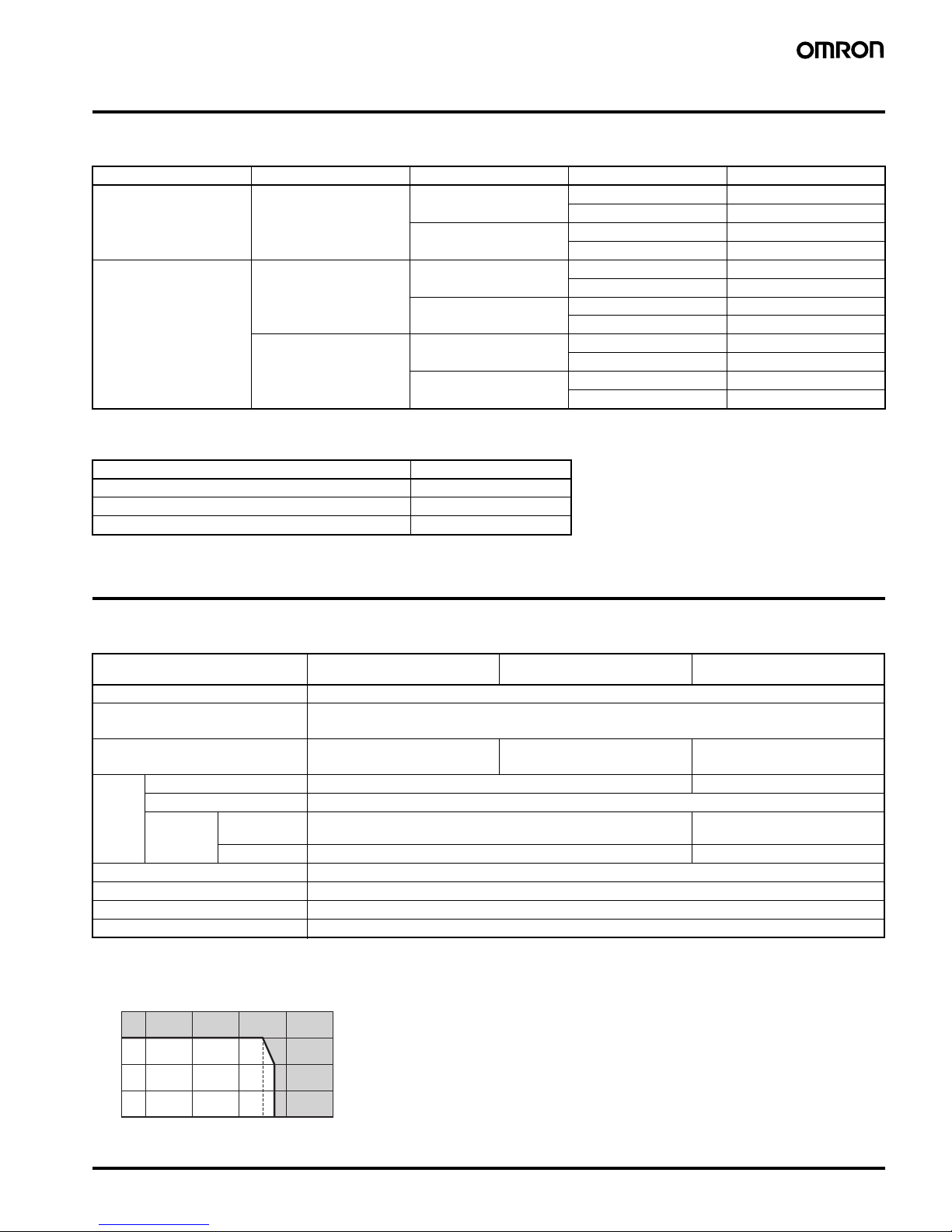
More Applications on New Series Models
Automatic Program Switching by Seasons
The yearly operation can be set to automatically change the weekly
program depending on the season. (See note.)
Note: Up to four seasons can be set for 4-circuit models, and up to
two seasons for 2-circuit models.
Temperature Compensation Circuit Maintains
Accurate Time
A temperature compensation circuit is provided in the yearly models
to maintain accurate time keeping even when the ambient
temperature varies greatly. This ensures precise operation with
minimal time lags all year round, regardless of temperature changes.
Space-saving, Economical 4-circuit Models Added
to the Series
The new 4-circuit models are 72 × 72-mm DIN size. Their spacesaving size allows use in more applications.
Model Number Structure
■ Model Number Legend
Note: This model number legend includes combinations that are not available. Please check the “List of Models” for availability.
1. Control cycle
W: Weekly
Y: Yearly
2. Mounting method
None: Flush mounting
F: Surface mounting/track mounting
3. Panel language
B: English
A: Japanese
4. Number of outputs
2: 2 circuits
4: 4 circuits
5. Supply voltage
None: 100 to 240 VAC
D: 24 VDC
6. Time accuracy
None: Standard
X: With temperature compensation
Yearly Models
Spring Summer Autumn Winter
Mar Apr May Jun Jul Aug Sep Oct Nov Dec Jan Feb
Season
(See note 2.)
Spring
17:30 ON
21:00 OFF
Summer
Program
example
19:00 ON
22:00 OFF
Winter
Autumn
18:00 ON
21:00 OFF
17:00 ON
21:00 OFF
4-circuit Models
Control all four
floors with a
single unit.
1 2 3 4 5
6
H5S- @@@@@ - @
Digital Time Switch H5S 3
Ordering Information
■ List of Models
■ Accessories (Order Separately)
Specifications
■ Ratings
Note: 1. Do not use inverter output as a power supply. For details, refer to Precautions for Safe Use, item 24, on page 12.
2. The capacity is 15 A per circuit, but derating of the total current for two circuits is required as shown below depending on the ambient
temperature.
Control cycle Number of outputs Mounting method Supply voltage Models
Weekly 2 circuits Flush mounting 100 to 240 VAC H5S-WB2
24 VDC H5S-WB2D
Surface mounting/
track mounting
100 to 240 VAC H5S-WFB2
24 VDC H5S-WFB2D
Yearly 2 circuits Flush mounting 100 to 240 VAC H5S-YB2-X
24 VDC H5S-YB2D-X
Surface mounting/
track mounting
100 to 240 VAC H5S-YFB2-X
24 VDC H5S-YFB2D-X
4 circuits Flush mounting 100 to 240 VAC H5S-YB4-X
24 VDC H5S-YB4D-X
Surface mounting/
track mounting
100 to 240 VAC H5S-YFB4-X
24 VDC H5S-YFB4D-X
Name Model
Large Terminal Cover (in pairs) Y92A-72H
Protective Cover Y92A-72C
Track Mounting Base Y92F-90
Item Weekly 2-circuit Models
(H5S-W@2)
Yearly 2-circuit Models
(H5S-Y@2)
Yearly 4-circuit Models
(H5S-Y@4)
Rated supply voltage 100 to 240 VAC (50/60 Hz), 24 VDC (See note 1.)
Operating voltage range AC: 85% to 110% rated supply voltage
DC: 85% to 120% rated supply voltage
Power consumption Approx. 2.9 VA at 264 VAC 60 Hz
Approx. 0.8 W at 28.8 VDC
Approx. 3.2 VA at 264 VAC 60 Hz
Approx. 0.9 W at 28.8 VDC
Approx. 3.5 VA at 264 VAC 60 Hz
Approx. 1.0 W at 28.8 VDC
Control
outputs
Number of circuits SPST-NO
× 2 circuits SPST-NO × 4 circuits
Circuits Power supply circuit and other (no-voltage) circuit
Capacity Resistive load
(cos
φ = 1)
15 A at 250 VAC (See note 2.) 3 A at 250 VAC
Inductive load 10 A at 250 VAC (cos
φ = 0.7) 2 A at 250 VAC (cosφ = 0.4)
Ambient operating temperature
−10 to 55°C (with no icing or condensation)
Ambient operating humidity 25 to 85%
Storage temperature
−25 to 65°C (with no icing or condensation)
Case color Light gray (Munsell 5Y7/1)
40
30
20
10
0
10 0 20 40 50 55 60 80
Ambient temperature (˚C)
Total current (A)
4 Digital Time Switch H5S
■ Characteristics
Note: 1. The total error including the repeat accuracy, setting error, variation due to voltage change, and variation due to temperature change is
±0.01% ±0.05 s max.
2. The total time when power is not being supplied.
Item Weekly 2-circuit Models
(H5S-W@2)
Yearly 2-circuit Models
(H5S-Y@2)
Yearly 4-circuit Models
(H5S-Y@4)
Accuracy of operating
time
±0.01%±0.05 s max. (See note 1.)
The
±0.01% value applies to the set time interval.
Setting error
Influence of voltage
Influence of temperature
Cyclic error
±15 s per month (at 25°C) ±15 s per month (at −10 to 45°C), ±20 s per month (at 45 to 55°C)
Memory protection Continuous use: 5 years min. (at 25
°C) (See note 2.)
Insulation resistance 100 M
Ω min. (between current-carrying terminals and exposed non-current carrying metal parts, between operation
circuit and control output circuit, between control output circuits, and between non-continuous contacts.)
Dielectric strength 2,950 VAC, 50/60 Hz for 1 min (between current-carrying terminals and exposed non-current carrying metal parts)
2,000 VAC, 50/60 Hz for 1 min (between operation circuit and control output circuit, and between control output
circuits)
1,000 VAC, 50/60 Hz for 1 min (between non-continuous contacts)
Noise immunity
±1,500 V (between power terminals, for AC power models), ±500 V (between power terminals, for DC power models)
Square-wave noise by noise simulator (pulse width: 100 ns, for 1
µs, 1-ns rise time)
Vibration
resistance
Destruction 10 to 55 Hz with 0.375-mm single amplitude in 3 directions for 2 hours each
Malfunction 10 to 55 Hz with 0.25-mm single amplitude in 3 directions for 10 minutes each
Shock
resistance
Destruction
300 m/s
2
3 times each in x, y, and z axes, 6 directions
Malfunction
100 m/s
2
3 times each in x, y, and z axes, 6 directions
Life
expectancy
Mechanical 100,000 operations min.
Electrical 50,000 operations min. (15 A at 250 VAC, resistive load)
50,000 operations min. (10 A at 30 VDC, resistive load)
50,000 operations min. (10 A at 250 VAC, inductive load (cos
φ = 0.7))
50,000 operations min. (1 HP at 250 VAC, motor load)
50,000 operations min. (100 W at 100 VAC, lamp load)
10,000 operations min. (300 W at 100 VAC, lamp load)
50,000 operations min. (3 A at 250
VAC, resistive load)
50,000 operations min. (3 A at 30
VDC, resistive load)
Approved standards cURus: UL 508/CSA C22.2 No.14,
Conforms to EN 60730-2-7(Pollution degree 2/overvoltage category II),
Conforms to VDE 0106/part100.
Conforms to Electrical Appliance and Material Safety Law (for Japan)
EMC (EMI) EN 60730-2-7
EMI Radiated: EN 60730-2-7 (CISPR 22 Class B)
EMI Conducted (Continuous): EN 60730-2-7 (CISPR 22 Class B)
EMI Conducted (Non-continuous): EN 60730-2-7 (CISPR 14-1)
Harmonic Current: EN 60730-2-7 (IEC 61000-3-2 Class A)
Voltage fluctuation/flicker: EN 60730-2-7 (IEC 61000-3-3)
(EMS) EN 60730-2-7
ESD Immunity: EN 60730-2-7 (IEC 61000-4-2): 6 kV contact discharge
8 kV air discharge
Radiated Electromagnetic Field Immunity: EN 60730-2-7 (IEC 61000-4-3): 10-V/m AM modulation
(80 MHz to 1 GHz, 1.4 GHz to 2 GHz)
10-V/m pulse modulation (900 MHz)
Conducted Disturbance Immunity: EN 60730-2-7 (IEC 61000-4-6): 10 V (0.15 to 80 MHz)
Burst Immunity: EN 60730-2-7 (IEC 61000-4-4): 2 kV power line
1 kV control line
Surge Immunity: EN 60730-2-7 (IEC 61000-4-5): 1 kV line to line (power line, output line)
2 kV line to ground (power line, output
line)
0.5 kV line to line (input line)
1 kV line to ground (input line)
Voltage Dip/Interrupting Immunity: EN 60730-2-7 (IEC 61000-4-11): 0.5-s cycle, 100% (rated voltage)
Weight Approx. 200 g
Digital Time Switch H5S 5
■ Operation
Note: 1. Depending the operation, the following steps can be used for weekly programs.
Timer operation: 2 steps
Pulse-output operation: 1 step
Cyclic operation: 4 steps
2. When the season switching setting is not being used.
3. When the season switching setting is being used.
■ Operation Functions
Item Weekly 2-circuit Models
(H5S-W@2)
Yearly 2-circuit Models
(H5S-Y@2)
Yearly 4-circuit Models
(H5S-Y@4)
Operation method Digital quartz
Operation period 1 week (7 days) 1 year (with integrated calendar to 2099)
Display • Day, hrs (switchable between 24-hr indication and a.m./p.m. 12-hr indication), minutes, seconds
(0.00 to 23:59, 0.00 to 11:59 a.m., 0.00 to 11:59 p.m.)
• Digital indication by LCD (character height: 10 mm)
• Digital display of operation schedule during operation
• Timing chart display of operation schedule during operation
Min. setting unit 1 min
Number of
steps that
can be set
Weekly program
(See note 1.)
40 steps/circuit 48 steps/circuit (See note 2.)
24 steps/circuit (See note 3.)
48 steps/circuit (See note 2.)
12 steps/circuit (See note 3.)
Yearly program --- 4 yearly programs/circuit
Number of
settable yearly
temporary
holiday settings
--- 16
Item Weekly 2-circuit Models (H5S-W@2) Yearly 2-circuit Models (H5S-Y@2) Yearly 4-circuit Models (H5S-Y@4)
Weekly timer
operation
Controls the output according to the set time of ON and OFF.
• Min. setting unit: 1 min
• Multiple-day operation also possible.
Weekly pulseoutput
operation
Output turns ON for a fixed period (pulse width) at the set ON time.
• Pulse width: 1 to 59 s (in 1-s increments), or 1 to 60 min (in 1-min increments)
• The pulse width can be set for each step.
Weekly cyclic
operation
Repeatedly turns ON and OFF during the period from the cyclic start time to the stop time.
Independent ON- and OFF-time settings are possible.
• Min. setting unit: 1 min
Yearly timer
operation
--- Adds a yearly timer operation to the weekly timer program.
For details, refer to About Yearly Programs on page 18.
Yearly pulseoutput
operation
--- Adds a yearly pulse-output operation to the weekly pulse-output program.
For details, refer to About Yearly Programs on page 18.
Temporary
holiday setting
Sets temporary holidays (non-operating days) without having to revise the existing program.
For details, refer to Setting Temporary Holidays (Weekly) and Setting Temporary Holidays (Yearly) on page 20.
Day override
operation
Executes the operation for one day
temporarily on another day in the 7-day
period starting from the current day.
For details, refer to Day Override
Operation on page 21.
---
Program check Consecutively displays the days and times when the output is set to turn ON and OFF over the course of one week in the
sequence in which the Time Switch is to operate.
For details, refer to Program Check Function on page 21.
ON OFF
Timer operation
Pulse output operation
ON
Pulse width
Cyclic operation
StopStart
ON
OFF

6 Digital Time Switch H5S
Checking the
settings
Consecutively displays the times when the output is set to turn ON and OFF for one day in the sequence in which the Time
Switch is to operate.
For details, refer to Checking the Settings on page 21.
Forced ON/OFF
operation
Allows the output to be forcibly turned ON/OFF by the Output ON/OFF Switch regardless of the control output setting.
Override and
automatic
return
operation
Allows the control output to be maintained in the ON (or OFF) state until the next OFF (or ON) time. This operation is controlled
by using the Output ON/OFF Switch and Write Key. When completed, the Time Switch automatically resumes the previously
set operation.
For details, refer to Override and Automatic Return Operation on page 22.
Summertime
(DST)
adjustment
Switches the current time from “current time” to “current time + 1 h” for daylight savings time. Yearly models also offer automatic
switching to daylight savings time.
For details, refer to Manual Summertime (DST) Adjustment on page 21.
Time counter/
total counter
display
Displays the total elapsed time and total count of external input. It also displays a
warning when a set value is entered.
For details, refer to Total Time/Count Display on page 23.
---
Time
adjustment
input
Allows the time to be set to 00 min 00 s at the same time as an external input is
applied.
For details, refer to Time Adjustment Input Function on page 24.
---
Manual
operation on
recovery from
power failure
Allows the output state to be specified following recovery from a power failure.
For details, refer to Manual Operation on Recovery from Power Failure on page 24.
---
Bank switching Allows two groups (banks) of programs to
be registered and switched by external
input.
For details, refer to Bank Switching on
page 24.
---
Season
switching
--- Allows weekly programs to be automatically switched in response to seasons
throughout the year.
For details, refer to Season Switching on page 24.
Power OFF
settings
Allows the display to remain lit even when the power is turned OFF, and settings to be made for all functions except Override
and Automatic Return Operation.
• The display illumination will turn OFF when there has been no operation for 2 min. The display will light again when any key
other than a slide switch is pressed for at least 1 s.
• No output will be generated.
Item Weekly 2-circuit Models (H5S-W@2) Yearly 2-circuit Models (H5S-Y@2) Yearly 4-circuit Models (H5S-Y@4)

Digital Time Switch H5S 7
Connections
■ Terminal Arrangement
H5S-@A@/-@B@ Flush Mounting Models
(2-circuit models) (4-circuit models)
H5S-@FA@/-@FB@ Surface Mounting Models
(2-circuit models) (4-circuit models)
Note: 1. The Time Switch output uses a no-voltage contact. An external power supply is required for applications in which a load is driven.
2. The output contact ratings are different for 2-circuit and 4-circuit models.
■ Input Connection (2-circuit Models Only)
Use a switch or relay as the input contact.
Use a contact that is capable of operating with 5 V, 0.1 A (with a minimum signal input width of 100 ms).
Note: Input must be selected using the “F2: Input selection” step of initial setting mode. For details, refer to Using Advanced Functions on page 23.
Output 2
Output 1Power
source
Input
+ ∼−
∼
(Rear View)
GAH
JI
DCB
Output 2 Output 3
Output 4
Output 1Power
source
+ ∼−
∼
(Rear View)
B
E
D
A
C
F
J
H
G
I
Output 2Input
Output 1
Power
source
− ∼+
∼
(Front View)
FGH
I
CB
D
E
Output 2Output 3
Output 4
Output 1 Power
source
− ∼+
∼
(Front View)
B
E
D
A
C
F
J
H
G
I
Flush mounting models
(H5S-@A2@/-@B2@)
Surface mounting models
(H5S-@FA2 @/-@FB2@)
G
J
F
I
8 Digital Time Switch H5S
Nomenclature
Front Panel (with Cover Open)
(Weekly 2-circuit models)
(Yearly 2-circuit models)
(Yearly 4-circuit models)
Key Operations
13. Day Keys
10. Time Adjustment
Key
12. Output
ON/OFF
Switches
1. Mode
Switch
2. Holiday/
Down Key
3. Write Key
4. m/Pulse Key
5. h Key
6. Reset Key
7. +1h/Clear
Key
8. Co
py/Cy
cle Ke
y
9. Test
Ke
y
11. Output
Setting
Switches
13. Day Keys
10. Time Adjustment
Key
12. Output
ON/OFF
Switches
1. Mode
Switch
2. Holiday/
Down Key
3. Write Key
4. m/Pulse Key
5. h Key
6. Reset Key
7. +1h/Clear
Key
8. Cycle Key
9. Test/
Year
Key
11. Output
Setting
Switches
13. Day Keys
10. Time Adjustment
Key
12. Output
ON/OFF
Switches
1. Mode
Switch
2. Holiday/
Select Program
/
Down Key
3. Write Key
4. m/Pulse Key
5. h Key
6. Reset Key
7. +1h/Clear
Key
8. Cycle Key
9. Test/
Year
Key
11. Output
Setting
Switches
No. Functions
1 (2-circuit models)
P1: Circuit (output) 1 Setting mode
P2: Circuit (output) 2 Setting mode
RUN: RUN mode
(4-circuit models)
PRGM: Setting mode (allows use of the Select Program Key
to set the circuit (output) number)
RUN: RUN mode
2 (2-circuit models)
In RUN mode, this key shifts the Time Switch to the Holiday
Setting mode
In Setting mode or Time Adjustment mode, this key
decrements the value for the operation just completed.
(4-circuit models)
In RUN mode, this key shifts the Time Switch to the Holiday
Setting mode.
When selecting the output, this key is used to set the circuit
(output) number.
In Setting mode or Time Adjustment mode, this key
decrements the value for the operation just completed.
3 Sets parameters.
4 Used to set the current time, ON/OFF time, or pulse width.
5
6 Used to reset all parameters, including the current time.
7 In RUN mode, this key sets or cancels summer time (+1 h)
In Setting mode, this key clears the parameter.
8 In RUN mode (weekly models only), this key shifts the Time
Switch to the Day Override operation setting mode.
In Setting mode, this key shifts the Time Switch to cyclic
operation setting.
9 In RUN mode, this key shifts the Time Switch to the Program
Check mode.
In Setting mode (yearly models only), this key is used to set
the yearly program.
10 This key shifts the Time Switch to the time adjustment mode.
11 TIMER: Executes a timer or cyclic operation.
PULSE: Executes a pulse-output operation.
12 ON: Turns ON the output regardless of the setting.
AUTO: Executes automatic operation as specified by these
settings.
OFF: Turns OFF the output regardless of the setting.
13 • Used to set the current day, operating day, etc.
• Used to specify the date (yearly models only)
• In RUN mode, these keys are used to shift the Time Switch
to the Checking the Settings mode.
Digital Time Switch H5S 9
Display
N
Display Description
No. Function
1 Lights when power is supplied to the Time
Switch.
2 When 12-hour display is selected, either AM
or PM lights. (24-hour display is the default.)
3 Lights when summer time (+1 h) is activated.
4 Displays the current time and other values.
5 Displays the unit for the pulse width.
6 Lights when the total time or count value
exceeds the alarm setting.
7 Displays the number of remaining steps for
programming in setting mode.
8 Displays the number of the circuit (output)
that has been set.
9 Displays the time for the next operation, the
date (yearly models only), and other values.
10 Displays the next operation and other
information in chart form.
11 Displays the bank name (weekly models) or
season name (yearly models).
12 Lights when setting the ON/OFF time or
when setting a day override operation.
13 Lit during the temporary holiday operation or
when setting a temporary holiday.
14 Lit during the day override operation or when
setting a day override operation.
15 Lit during setting a yearly program.
16 Flashes during the Time Adjustment mode.
17 Displays the current day or the day set for an
operation.
18 Displays the number of the circuit (output) for
which output is ON.
(Weekly 2-circuit models)
5. Pulse width unit indicato
r
4. Main display
9. Sub-display
10. Timing chart display
17. Day indicator
11. Bank indicator
12. From/To indicator
14. Copy indicator
1. Power indicator
2. AM/PM indicator
3. Summer time indicator
2. AM/PM indicator
13. Holiday indicator
7. Display of number
of remaining steps
8. Set circuit number
indicator
6. Total value alarm
indicator
18. Output circuit number
indicator
16. Time adjustment mode
indicator
(Yearly 2-circuit models)
4. Main display
9. Sub-display
10. Timing chart display
17. Day indicator
11. Season indicators
12. From/To indicator
13. Holida
y
indicator
1. Power indicator
2. AM/PM indicator
3. Summer time indicator
2. AM/PM indicator
15. Year indicator
7. Display of number
of remaining steps
8. Set circuit number
indicator
6. Total value alarm
indicator
16. Time adjustment mode
indicator
5. Pulse width unit
indicator
18. Output circuit number
indicator
(Yearly 4-circuit models)
4. Main display
9. Sub-display
10. Timing chart displa
y
17. Day indicators
11. Season indicator
12. From/To indicator
13. Holida
y
indicator
1. Power indicator
2. AM/PM indicator
3. Summer time indicator
2. AM/PM indicator
15. Year indicator
7. Display of number
of remaining steps
8. Set circuit number
indicator
16. Time adjustment mode
indicator
5. Pulse width unit
indicator
18. Output circuit number
indicator
 Loading...