

Omron H5F-B, H5F-FB, H5F-KB Datasheet
Digital Daily Time Switch H5F 1
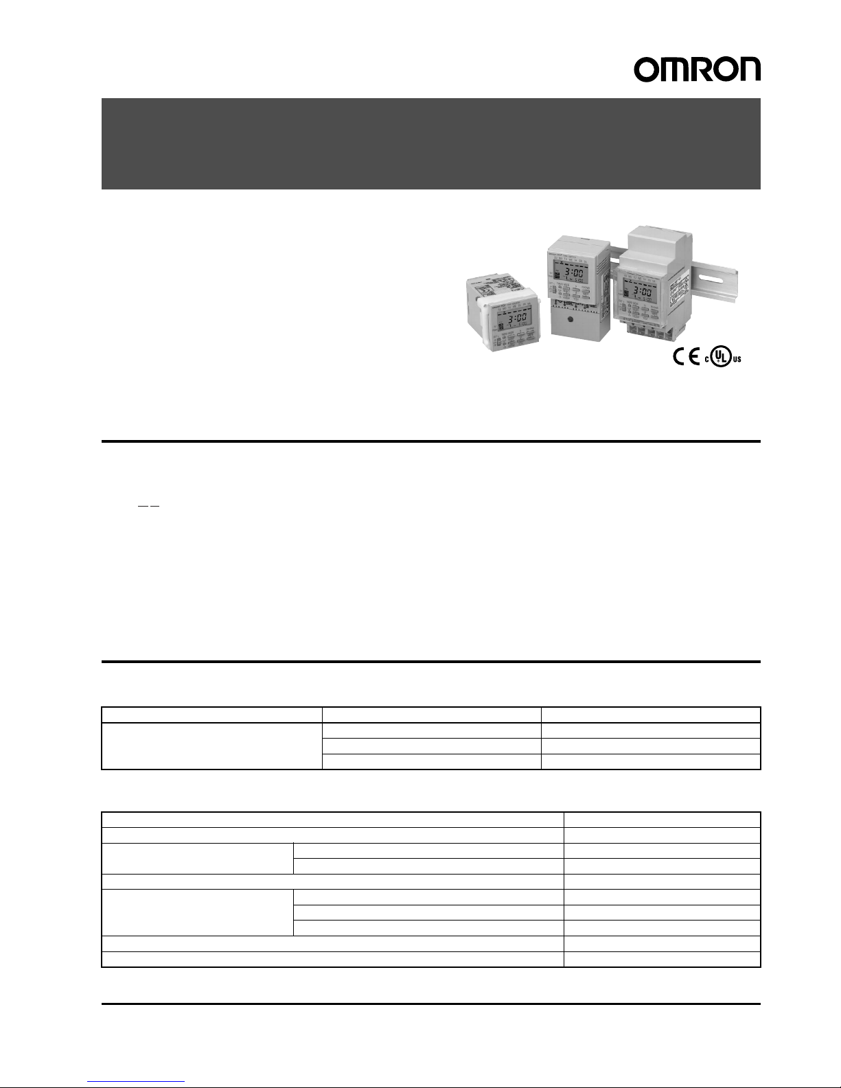
Digital Daily Time Switch
H5F
Daily Time Control with Simple Operations
(Operation Day Selection Possible)
• Up to 12 ON/OFF operations (24 for pulse-output operation).
• Special holidays can be handled easily with the holiday setting
function.
• Adjustments f or su dden s chedu le cha nges c an be ma de eas ily
using output override and automatic return operation.
• The operation p rogr am can be che ck ed ea sily wit h the progra m
check function.
• Enables pulse output operation and summer time setting.
• Incorporates finger-safe terminals.
• Conforms to UL, CSA, and CE marking.
• Meets a variety of mounting requirements: flush mounting, surface mounting, and DIN track mounting.
Model Number Structure
■Model Number Legend
1. Mounting method
None: Flush mounting
F: Surface mounting
K: Surface mounting/track mounting
2. Language
B: English
Ordering Information
■List of Models
■Accessories (Order Separately)
Note: 1. Supplied with H5F-KB model.
2. Supplied with H5F-B (flush-mounting) model.
12
H5F-@B
Wiring Mounting method Mode l
Screw terminals Flush mounting H5F-B
Surface mounting H5F-FB
Surface mounting/track mounting H5F-KB
Name Models
Soft cover Y92A-48F1
Hard cover For H5F-B Y92A-48
For H5F-FB/-KB Y92A-48E (See note 1.)
Flush Mounting Adapter (See note 2.) Y92F-30
Mounting Track 50 cm (l)
´ 7.3 mm (t) PFP-50N
1 m (l)
´ 7.3 mm (t) PFP-100N
1 m (l)
´ 16 mm (t) PFP-100N2
End Plate PFP-M
Spacer PFP-S
2 Digital Daily Time Switch H5F
Specifications
■Ratings
■Characteristics
Note: 1. The total error including the repeat accuracy, setting error, variation due to voltage change, and variation due to temperature change is
±0.01%±0.05 s max. ±0.01% also indicates an error in the time interval of a set time.
2. The total time when power is not being supplied.
Rated supply voltage 100 to 240 VAC (50/60 Hz)
Operating voltage range 85% to 110% of rated supply voltage
Power consumption Approx. 2.4 VA at 264 VAC
Control outputs Contact output: SPST-NO, 15 A at 250 VAC, resistive load, 10 A at 24 VDC, resistive load
Minimum applied load: 100 mA at 5 VDC (failure level: P, reference value)
NEMA A300 Pilot Duty, 1/3 HP at 120 VAC
External connections Screw terminals (M3.5 screw)
Termi na l s c r ew tightening torque 0.98 to 1.17 N · m
Accuracy of operating time ±0.01% ±0.05 s max. (see note 1)
Setting error
Influence of voltage
Influence of temperat ure
Cyclic error Monthly difference
±15 s (at 25°C)
Memory protection Continuous use: 5 years min. (at 25
°C); Power-interruption rate of 50%: 10 years min. (at 25°C) (see note 2)
(lithium battery)
Insulation resistanc e 100 M
W min. (between current-carrying terminals and exposed non-current-carrying metal parts, between operating
power supply circuit and control output circuit and between non-continuous contacts )
Dielectric strength 2,000 V A C , 50/6 0 Hz f or 1 min (betw een curren t-carrying terminals and e xposed non-curren t-carrying metal parts and
between operating power supply circuit and control output circuit)
1,000 VAC, 50/60 Hz for 1 min (between non-continuous contacts)
Noise immunity 1.5 kV (between power terminal s)
Square-wave noise by noise simulator ( pulse width: 100 ns/1
ms, 1-ns rise)
Vibration resistance Destruction:10 to 55 Hz with 0.375-mm single amplitude, four cycles each in three directions (8 minutes per cycle)
Malfunction:10 to 55 Hz with 0.2 5-mm single amplitude for 10 minutes each in t hree directions
Shock resistance
Destruction:300 m/s
2
3 times each in 6 directions
Malfunction:100 m/s
2
3 times each in 6 directions
Ambient temperature Operating:–10
°C to 55°C (with no icing)
Storage: –25
°C to 65°C (with no icing )
Ambient humidity Operating: 35% to 85%
Life expectancy Mechanical (at 20
°C):
100,000 operations min.
Electrical (at 20
°C):
50,000 operations min. (15 A, 250 VAC, resistive load)
50,000 operations min. (1 HP, 250 VAC, motor load)
50,000 operations min. (10 A, 250 VAC, inductive load (cos
f = 0.7))
50,000 operations min. (100 W, 100 VAC, lamp load)
10,000 operations min. (300 W, 100 VAC, lamp load)
Approved safety standards UL508/Listing, CSA C22.2 No. 14, conf orms to EN61010-1 (Pollution degree 2/overvoltage category II)
Conforms to VDE0106/P100 (finger protection).
Conforms to Electrical Appliance and Material Safety Law (for Japan)
EMC (EMI) EN61326
Emission Enclosure: EN55011 Group 1 class A
Emission AC mains: EN55011 Group 1 class A
(EMS) EN61326
Immunity ESD: EN61000-4-2: 4 kV contact discharge (le vel 2)
8 kV air discharge (level 3)
Immunity RF-interf erence: EN 61000-4-3: 10 V/m (Amplitude-modulated, 80 MHz to 1 GHz,
1.4 to 2 GHz) (level 3)
Immunity Conducted
Disturbance: EN61000-4-6: 10 V (0.15 to 80 MHz) (according to EN61000-6-2)
Immunity Burst: EN61000-4-4: 2 kV power-line (level 3)
1 kV I/O signal-line (level 4)
Immunity Surge: EN61000-4-5: 1 kV line to lines (power and output lines) (level 2);
2 kV line to ground (power and output lines) (level 3)
Immunity Voltage Dip/Interruption: EN61000-4-11: 0.5 cycle, 100% (rated voltage)
Immunity Magnetic Power Field: EN61000-4-8: 30 A/m
Case color Light gray (Munsell 5Y7/1)
Weight H5F-B: approx. 115 g; H5F-KB: approx. 160 g; H5F-FB: approx. 130 g
Digital Daily Time Switch H5F 3
Connections
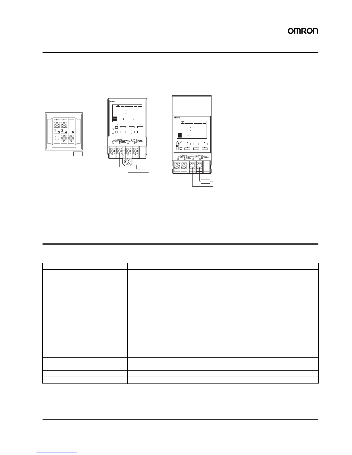
■Terminal Ar rangement
Note: 1. The Time Switch uses M3.5 terminals.
2. The Time Switch output is no-voltage contact output. An external power supply is required to drive the load.
3. Applicable wire: 600-V vinyl-insulated wire (solid wire or twisted wire, copper), 14 to 24 AWG, 2 wires max. per terminal.
4. Applicable tightening torque: 0.98 to 1.17 N·m.
5. Recommended fuse: T2A, 250 VAC, time delay, low breaking capacity.
Operation
■Operation
Note: Up to 12 ON/OFF operations are possible per day. (For pulse-output operation, the number is 24.)
H5F-B H5F-FB
H5F-KB
PW
ON
PM
PM
3 00
5 00
H5FTIME SWITCH
SU MO TU WE TH FR SA
PW
ON
PM
PM
3 00
5 00
H5FTIME SWITCH
SU MO TU WE TH FR SA
Flush Mounting Models
Power source
100 to 240 VAC
Power source
100 to 240 VAC
Power supply
of load
Load
Power supply
of load
Load
Power source
100 to 240 VAC
Power supply
of load
Load
Surface Mounting Models
Surface Mounting/Track Mounting Models
(Rear View)
(Front View)
(Front View)
WRITE
m
/ WD
dhSELECT
MODE
CLR
OUT
POWER
ON
AUTO
OUT
OFF
TESTHOLIDAY+1h
TMR/
P
P
WRITE
m
/ WD
dhSELECT
MODE
CLR
OUT
POWER
ON
AUTO
OUT
OFF
TESTHOLIDAY+1h
TMR/
P
P
Operation method Digital quartz
Time range 24 h
´ 7 days (Operation days can be specified.)
Operation 1. Daily operation (Multiple-day operation possible.)
2. Pulse-output operation (Pulse width can be set in units of 1 s from 1 to 59 s and in units of 1min
from 1 to 60 min.)
3. Partial operation on specified day (One or some of the operations for certain days can also be
executed on other days.)
4. Forced ON/OFF operation
5. Holiday operation
6. Output override and automatic return operation
Display 1. Day, hours (12-hour (am/pm) or 24-hour clock), minutes (0:00 to 11:59 a.m./ 0:00 to 11:59 p.m.,
0:00 to 23:59)
2. Digital display by LCD. Character height: 8 mm
3. Digital display of present time and time schedules for operation
4. Timing chart display of present time and time schedules for operation
Other funct io ns Program check function, summer time function
Number of circuits 1 independent circuit
Minimum setting unit 1 min
Minimum set interval 1 min
Number of operations that can be set 24 (see note)
4 Digital Daily Time Switch H5F
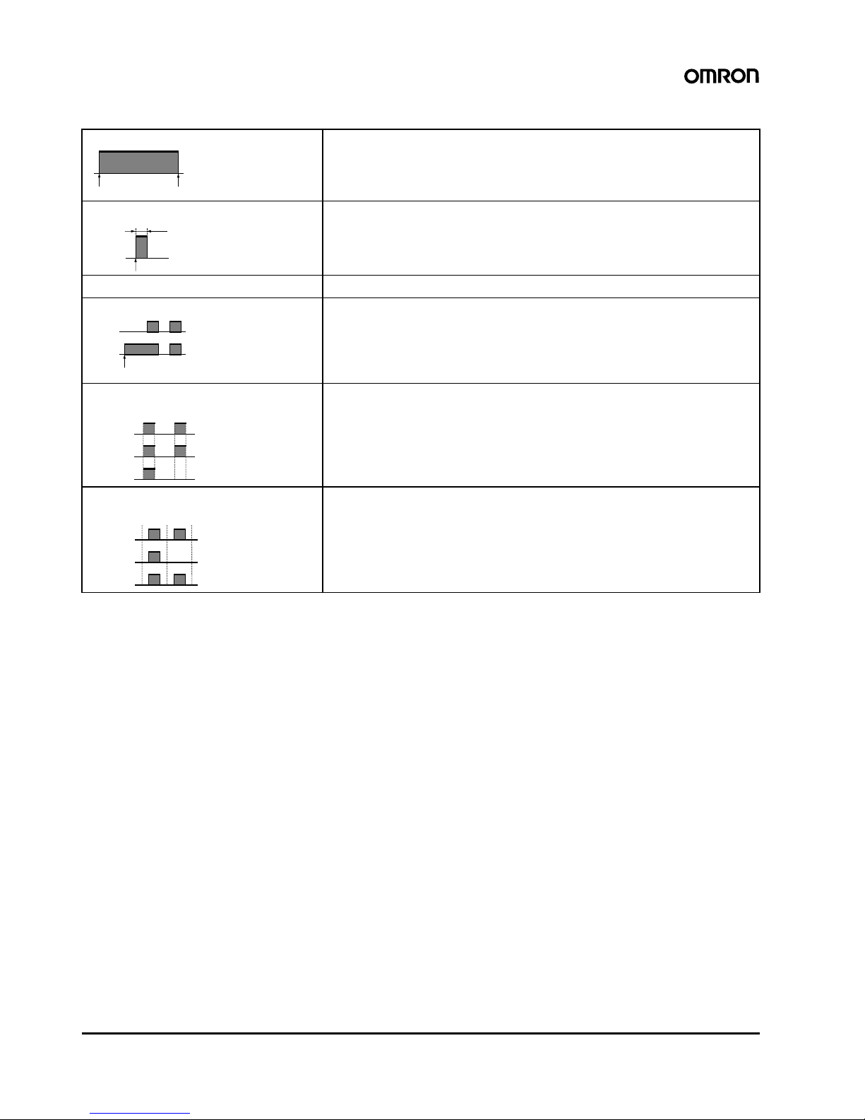
■Operation Function s
Note: Both the timer operation and the pulse-output operation cannot be programmed together.
■Operation When Power Turn s OF F
1. The time and settings are backed up using a lithium battery .
2. The display stays ON but the output turns OFF.
3. Settings for all types of operation except override and automatic
return operation are possible.
Timer operation (ON/OFF operation) Controls the output according to preset of ON and OFF times
• Minimum setting unit: 1 min
• Up to 12 ON/OFF operations are possible per day.
Pulse-output operation Output turns ON for a fixed period (pulse width) at the set time.
• Pulse width: 1 to 59 s, or 1 to 60 min. (The same pulse width setting is used for all types of
output operation.)
• The pulse width can be set in units of 1 s or 1 min.
• Up to 24 pulse-output operations are possible per day.
Forced ON/OFF operation Forcibly turns ON/OFF the output by the output ON/OFF switch.
Override and automatic return operation Using the output ON/OFF switch and the Write Key, control output is held in the ON state until
the next OFF time.
• It is also possible to hold the control output in the OFF state until the next ON time.
• Operation after the output turns OFF (or ON) will be based on the regular program.
• This function can be used with pulse-output operation.
Partial operation on specified day The Time Switch operates according to only some of the programs on a user-specified day.
(Convenient, for example, for executing a half-day operation on Saturday.)
• It is not possible to set operation to be executed only on the specified day.
• This function can be used with pulse-output operation.
Holiday setting It is possible to set a day in the present week as a holiday (i.e., a non-operation day: output
OFF regardless of the settings). When that day has passed, operation will continue according
to the regular program, and operation will be executed as normal on that day from the following week
• This function can be used with pulse-output operation.
ON time
OFF time
ON time
Pulse width
Output
operation
Regular
program
Start of override and
automatic return operation
Operation on
operation day
Operation on
specified day
Regular
program
Program 1
(special)
Program 2
Operation from
next week
Operation in
present week
Operation on
operation day
Regular
program
Operation
on holiday
Digital Daily Time Switch H5F 5
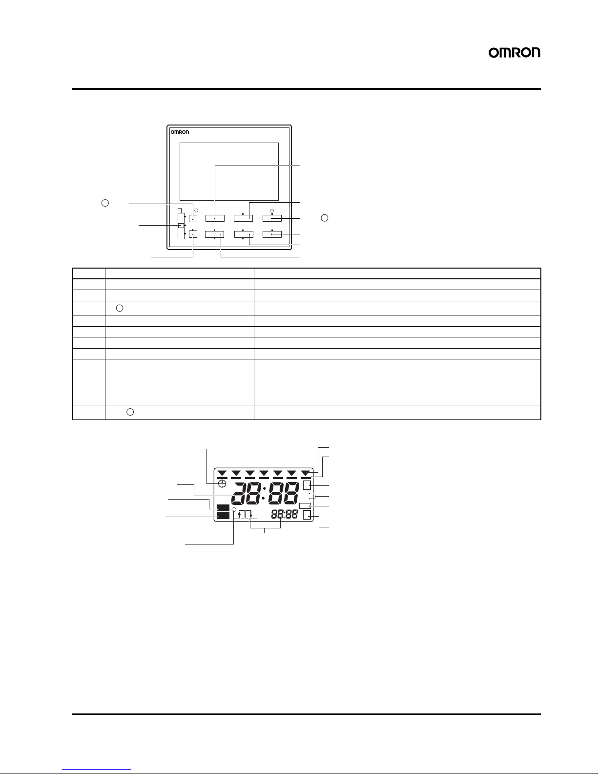
Nomenclature
Front Panel
Display
No. Name Function
A Mode Key Switches between time adjustment mode, the operation setting modes, and run mode.
B h (Hour) Key Sets hours or switches between 12-hour (am/pm) and 24-hour display.
C Sets minutes or a pulse time width.
D Write Key Writes the set data to memory or confirms settings with the program check function.
E d/Test (Day Shift/Program Test) Key Moves the cursor to specify a day or starts the program check function.
F Select/Holiday Key Specifies or cancels a specified day or switches to holiday setting mode.
G CLR/+1h (Clear/Summer Time) Key Erases the set data and initializes the day of operation or sets/clears summer time.
H Output ON/OFF switch ON: Turns on the output regardless of the setting.
AUTO: Turns on/off the output according to the setting.
OFF: Turns off the output regardless of the setting.
Override and automatic return operation can be executed by using this key in combination with the Write Key.
I Selects timer operation or pulse-output operation.
A Mode Key
H Output ON/OFF
Switch
G CLR/+1h Key
B h Key
C m/ WD Key
D Write Key
E d/Test Key
F Select/Holiday Key
I TMR/ Key
P
P
(Actual Size)
H5FTIME SWITCH
SU MO TU WE TH FR SA
WRITE
m/
WD
d
h
SELECT
MODE
CLR
OUT
POWER
ON
AUTO
OUT
OFF
TEST
HOLIDAY
+1h
TMR/
P
P
m/ WD (Minute/Pulse Time Width) Key
P
TMR/ (Timer/Pulse output) Key
P
ON
AM
PM
AM
PM
P
S
+1h
s
m
P
PW
SU MO TU WE TH FR SA
Time Adjustment Mode Indicator
Displays the Present Time,
Operation Time, and Time Width
Output Indicator
Pulse Operation Indicator
Partial Operation on Specified Day Indicator
Pulse Width Unit Indicator
Operation Setting Mode Indicator
Next Operation Indicators
Lit when control output is ON.
Lit: Pulse-output operation
Not lit: Timer operation
Lit: Operation day
Not lit: Non-operation day
Flashing: Specified operation day
Power Indicator
Lit when power is supplied
to the Time Switch.
Run mode: Displays the direction (i.e., ON or
OFF) and time of the next output
operation.
Operation time setting mode: Displays the program number for
the setting.
Holiday setting mode: Displays hday (hday) when the
Time Switch is in holiday setting
mode.
Program check: Displays test (test) during
program check.
Summer Time Indicator
Lit when set to summer time.
Present Day Indicator
Operation Day Indicator
 Loading...