

Page 1
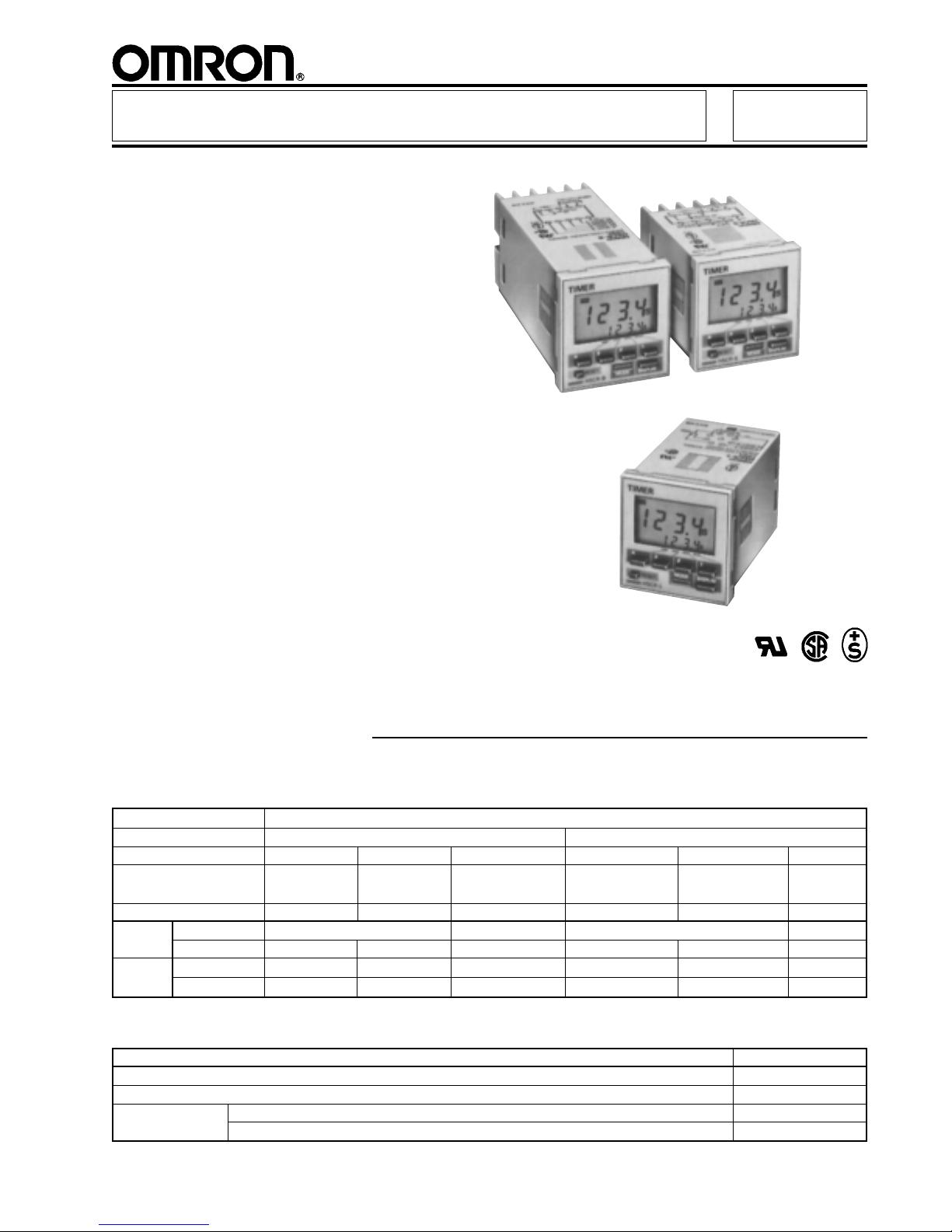
Multifunction Digital Timer H5CR
1/16 DIN Timer with
Easy-to-Use Functions
■ Nine field-selectable output
modes accommodate a wide
variety of applications
■ All parameters set by scroll through menus accessed from
the front panel
■ Field-selectable time ranges from
0.001 second to 9999 hours
■ High-visibility alphanumeric LCD
display has 8 mm high characters
and built-in backlight
■ Precision control possible to
0.001 second
■ Four levels of key protection provided
■ 10-year battery back-up
■ Selectable elapsed time (UP)
and time remaining (DOWN) display
■ Short body model H5CR-S measures
just 64 mm (2.52 inches) deep
Ordering Information
■ TIMERS
Add the supply voltage to the part number when you order. For example, H5CR-B-AC100-240.
Timing functions 9 selectable, including ON-delay, repeat cycle, OFF-delay, and one-shot
Contact type SPDT relay Solid-state open collector
Product type Economy Standard Short body Economy Standard Short body
Unit depth 78 mm 100 mm 64 mm 78 mm 100 mm 64 mm
(3.07 in) (3.94 in) (2.52 in) (3.07 in) (3.94 in) (2.52 in)
Panel mounting hardware Not provided Provided Provided Not provided Provided Provided
Supply AC 24 V or 100 to 240 V; 50/60 Hz — 24 V or 100 to 240 V; 50/60 Hz —
voltage DC 12 to 24 V — 12 to 24 V 12 to 24 V — 12 to 24 V
Part Backlit display — H5CR-B H5CR-S — H5CR-BS H5CR-SS
number Unlit display H5CR-L — — H5CR-LS — —
■ ACCESSORIES
Description Part number
Soft cover with two mounting clips for front panel protection Y92A-48F1
Shock prevention terminal cover for Standard and Short body timers protects wiring connections Y92A-48T
Sockets for Bottom surface or track mounting, top screw terminals P2CF-08
economy timers Back mounting, for use with Y92F-30 mounting adapter, bottom screw terminals P3G-08
H5CR 1
Page 2
H5CR H5CR
■ REPLACEMENT PARTS
Description Part number
Panel mounting bracket (one supplied with H5CR-B and H5CR-S models) Y92F-30
■ RANGE AND OPERATION MODE SELECTION
Range selection Time unit Maximum setting
- . - - - s 0.001 second 9.999 seconds
- - . - - s 0.01 second 99.99 seconds
- - - . - s 0.1 second 999.9 seconds
- - - - s 1 second 9999 seconds
- - min - - s 1 second 99 minutes 59 seconds
- - - . - min 0.1 minute 999.9 minutes
- - - - min 1 minute 9999 minutes
- - hr - - min 1 minute 99 hours 59 minutes
- - - . - hr 0.1 hour 999.9 hours
- - - - hr 1 hour 9999 hours
Mode Operation Output type
A ON-delay Sustained or
A-1 Sustained start signal ON-delay one-shot*
A-2 Power ON-delay
A-3 Power ON-delay/non-power
resettable
B Repeat cycle
B-1 Repeat cycle/non-power
resettable
D OFF-delay Sustained
E One-shot
F Cumulative signal ON-delay
*One-shot time, seven choices selectable:
0.1 sec, 0.5 sec, 1 sec, 5 sec, 10 sec, 15 sec, 20 sec
Specifications
Part number H5CR-L H5CR-B H5CR-S
Classification Economy type Standard type Short body type
Supply
voltage
Operating voltage 85% to 110% of rated voltage
Power
consumption
Inputs Types available Reset and start signal Reset, gate, start signal, and key protect
Signal, Type No-voltage input
reset ON impedance 1 kΩ max. (Approx. 2 mA when 0Ω)
and gate Residual voltage 2 V max. in ON state
Key Type No-voltage input
protect ON impedance 100 kΩ max. (Approx. 2 mA when 0Ω)
Control
output
Repeat accuracy Power start ±0.01%, ±0.05 second max.
Setting error —
Resetting system Power reset (A, A-1, A-2, B, D and E modes)
Resetting time Power reset 0.5 second minimum (A, A-1, A-2, B, D and E modes)
Indicators 4-digit LCD alphanumeric 4-digit LCD alphanumeric display with backlighting
Type Time limit SPDT relay output or NPN open collector transistor output (H5CR-❑S)
Relay Max. load 5 A, 250 VAC resistive load (p.f. = 1)
Solid- Max. load 100 mA, 30 VDC
state Residual voltage 2 V max., 1 V typical
2
AC 100 to 240 VAC, 50/60 Hz, 100 to 240 VAC, 50/60 Hz, —
24 VAC, 50/60 Hz 24 VAC, 50/60 Hz
DC 12 to 24 VDC, 20% max. — 12 to 24 VDC, 20% max.
permissible ripple permissible ripple
AC 3 VA at 60 Hz, 240 VAC —
DC 1 W at 24 VDC — 2 W at 24 VDC
OFF impedance 100 kΩ minimum
Pulse width 1 ms or 20 ms selectable for reset and signal
20 ms for gate
Residual voltage 1 V max. in ON state
OFF impedance 100 kΩ minimum
Response time 1 second
Instantaneous —
Min. load 10 mA, 5 VDC
Signal start ±0.005%, ±0.03 second max. (rate for set value)
External, manual, automatic resets (may be internal depending on A-1, B, B-1, D and E
operation modes)
display without backlighting 8 mm (0.32 in) H present value, 4 mm (0.16 in) H set value
8 mm (0.32 in) H present
value, 4 mm (0.16 in) H
set value
Page 3
H5CR H5CR
SPECIFICATIONS continued
Memory function Retains preset values for 10 years at 25° C (77° F)
Materials Plastic case
Mounting Panel or surface; Y92F-30 Panel, Y92F-30 mounting bracket included
Connections 8-pin round socket Screw terminals
Weight 105 g (3.7 oz.) 160 g (5.6 oz.) 120 g (4.2 oz.)
Approvals UL/CSA/SEV
Operating ambient temperature -10° to 55°C (14° to 131°F) with no icing
Humidity 35% to 85% RH
Vibration Mechanical durability 10 to 55 Hz with 0.75 mm single amplitude in 3 directions
Malfunction durability 10 to 55 Hz with 0.5 mm single amplitude in 3 directions
Shock Mechanical durability 30 G each in three directions
Malfunction durability 10 G each in three directions
Variation due to voltage change Included in "Repeat accuracy" specification
Variation due to temperature change Included in "Repeat accuracy" specification
Insulation resistance 100 MΩ min. at 500 VDC between current-carrying terminal and exposed non-current-
Dielectric strength 2,000 VAC, 50/60 Hz for 1 minute between current-carrying terminal and exposed
Service life Mechanical 10 million operations minimum
(SPDT relay) Electrical 100,000 operations minimum at 5 A, 240 VAC, resistive load (p.f. = 1)
mounting bracket included
carrying metal parts, and between non-continuous contacts.
non-current-carrying metal parts for 100 to 240 VAC type
1,000 VAC for both 24 VAC and 12 to 24 VDC types
Timing Charts
■ OPERATION MODES
The gate input is not included on "economy" models H5CR-L and H5CR-LS.
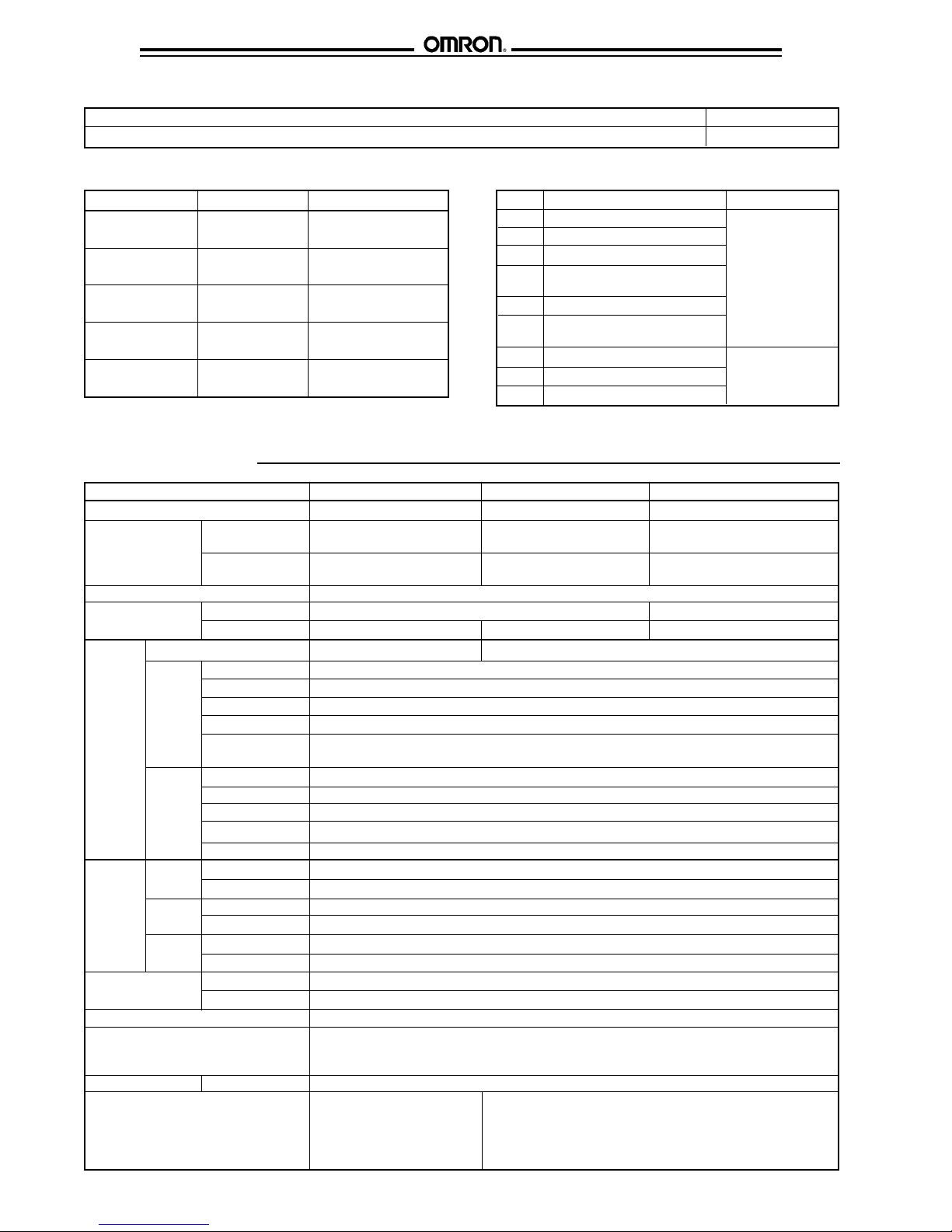
Output mode A: Signal ON delay 1 (Timer resets when power comes on.)
Power
Start signal
Gate
Reset
Control output
Set value
Timing
diagram
Output mode A1: Signal ON delay 2 (Timer resets when power comes on.)
Timing
diagram
UP 0
Set value
DOWN 0
Power
Start signal
Gate
Reset
Control output
Set value
UP 0
Set value
DOWN 0
Timing begins at the leading edge of
the start signal. The control output will
be energized when the present value
equals the preset time. The output will
be sustained until a reset signal is
applied, until power is interrupted, or
for a programmable one-shot time
period.
Timing begins at the leading edge of the
start signal. The control output will be
energized if the start signal is sustained
for an amount of time equal to the preset
time. The output will be sustained until
the start signal is interrupted, until a reset
signal is applied, until power is
interrupted, or for a programmable oneshot time period.
One-shot
Sustained output
One-shot outputs can be set to 0.1 s, 0.5 s, 1 s, 5 s, 10 s, and 20 s.
3
Page 4
H5CR H5CR
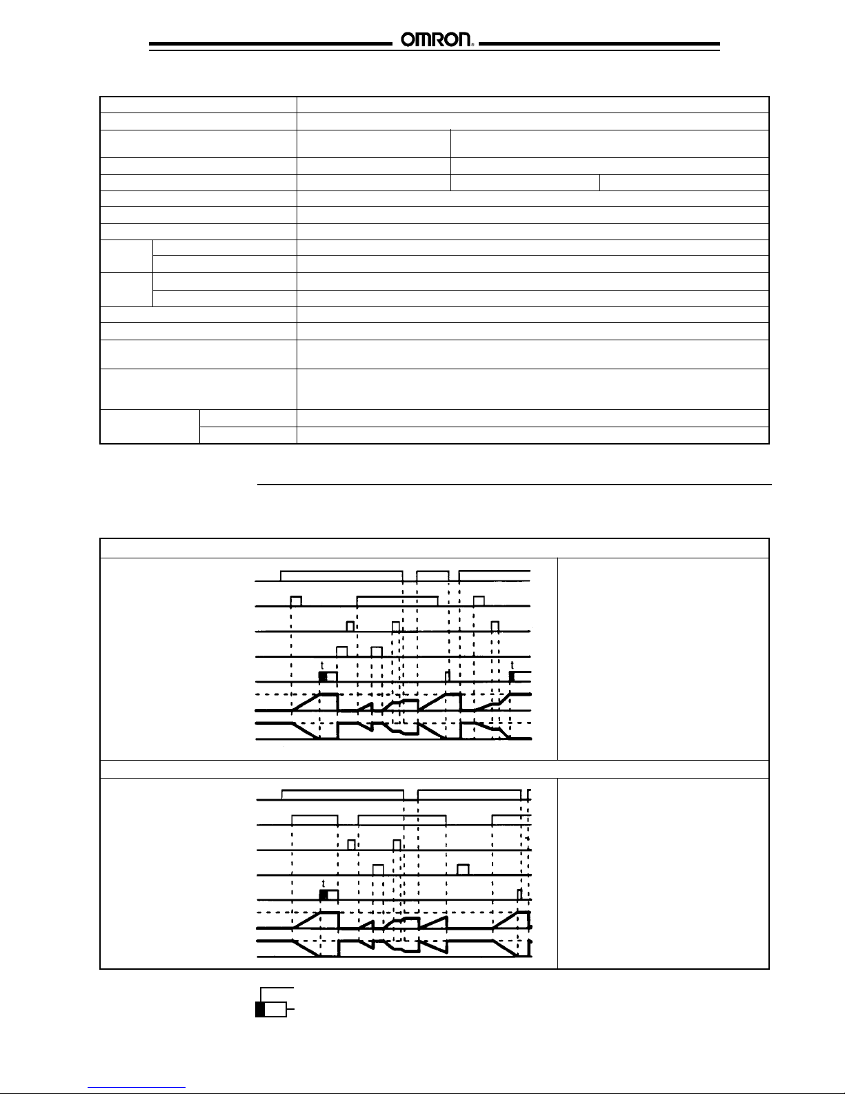
Output mode A-2: Power ON delay 1 (Timer resets when power comes on.)
Power
Start signal
Gate
Reset
Control output
Set value
Timing
diagram
Output mode A-3: Power ON delay 2 (Timer does not reset when power comes on.)
Timing
diagram
UP 0
Set value
DOWN 0
Power
Start signal
Gate
Reset
Control output
Set value
UP 0
Set value
DOWN 0
Timing begins when power is applied.
Start signals act as a gate input,
causing the present value to hold. The
control output will be energized when
the present value equals the preset
time. The output will be sustained until
a reset signal is applied, until power is
interrupted, or for a programmable
one-shot time period.
Timing begins when power is applied.
Start signals act as a gate input, causing
the present value to hold. The control
output will be energized when the
present value equals the preset time.
The output will be sustained until a reset
signal is applied or for a programmable
one-shot time period. If power to the unit
is interrupted, the control output will be
de-energized. The output will reenergize once power is restored.
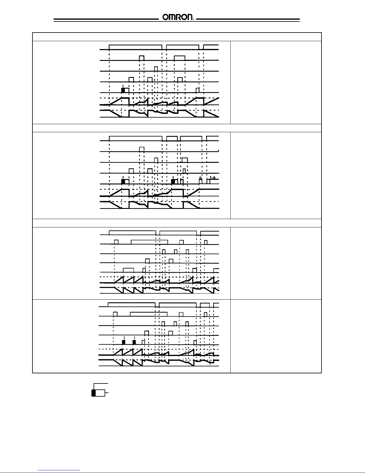
Output mode B: Repeat cycle 1 (Timer resets when power comes on.)
Power
Start signal
Gate
Reset
Control output
Set value
Timing
diagram
Timing
diagram
UP 0
Set value
DOWN 0
Power
Start signal
Gate
Reset
Control output
Set value
UP 0
Set value
DOWN 0
One-shot
Sustained output
One-shot outputs can be set to 0.1 s, 0.5 s, 1 s, 5 s, 10 s,
and 20 s.
a = one-shot time before power interruption
t-a = remaining one-shot time after power interruption
The OFF/ON cycle is initiated at the
leading edge of the start signal. The
output relay will be OFF for the preset
time, then ON for the preset time. The
cycle will be repeated until a reset input
is applied or power is interrupted.
The OFF/ON cycle is initiated at the
leading edge of the start signal. The
control output will be OFF for the first
cycle. In subsequent cycles the output
will be ON for the programmable oneshot time period, then OFF for the
remainder of the preset time. The cycle
will be repeated until a reset input is
applied or power is interrupted.
4
Page 5

H5CR H5CR
Output mode B-1: Repeat cycle 2 (Timer does not reset when power comes on.)
The OFF/ON cycle is initiated at the
leading edge of the start signal. The
Start signal
Gate
Reset
Control output
Timing
diagram
Timing
diagram
Output mode D: Signal OFF delay (Timer resets when power comes on.)
Set value
UP 0
Set value
DOWN 0
Power
Start signal
Gate
Reset
Control output
Set value
UP 0
Set value
DOWN 0
Power
Start signal
Gate
Reset
output relay will be OFF for the preset
time, then ON for the preset time. The
cycle will be repeated until a reset input
is applied. If power to the unit is
interrupted, the present value will hold.
The cycle will continue from that point
once power is restored.
The OFF/ON cycle is initiated at the
leading edge of the start signal. The
control output will be OFF for the first
cycle. In subsequent cycles the output
will be ON for the programmable oneshot time period, then OFF for the
remainder of the preset time. The cycle
will be repeated until a reset input is
applied. If power to the unit is
interrupted, the present value will hold.
The cycle will continue from that point
once power is restored.
The control output is energized at the
leading edge of the start signal. Timing
begins at the trailing edge of the start
signal. The control output is deenergized when the present value equals
the preset time.
Control output
Set value
diagram
Output mode E: Interval (Timer resets when power comes on.)
Timing
diagram
UP 0Timing
Set value
DOWN 0
Power
Start signal
Gate
Reset
Control output
Set value
UP 0
Set value
DOWN 0
One-shot
Sustained output
Timing begins on the leading edge of the
start signal. The control output is only
energized during timing. The timer is
reset when power is interrupted or a
reset signal is applied.
One-shot outputs can be set to 0.1 s, 0.5 s, 1 s, 5 s, 10 s,
and 20 s.
a = one-shot time before power interruption
t-a = remaining one-shot time after power interruption
5
Page 6

H5CR H5CR
Output mode F: Cumulative (Timer does not reset when power comes on.)
Power
Start signal
Gate
Reset
Timing begins on the leading edge of the
start signal. The control output is
energized when the cumulative elapsed
time of the start signal is equal to the
preset time. The output is sustained until
power is interrupted or a reset signal is
applied.
Control output
Set value
Timing
diagram
UP 0
Set value
DOWN 0
Dimensions
Unit: mm (inch)
■ TIMERS
Economy Models H5CR-L, H5CR-LS
84.0
48
(1.89)
6
(0.24)
(3.31)
63.7
(2.51)
0.7
(0.03)
14.3
(0.56)
48
(1.89)
Standard Models H5CR-B, H5CR-BS
48
(1.89)
Short Body Models H5CR-S, H5CR-SS
48
(1.89)
48
(1.89)
48
(1.89)
6
(0.24)
6
(0.24)
64
(2.52)
100
(3.94)
M3.5 terminal screw,
effective length: 6 mm (0.24 in)
44.8
(1.76)
44.8
(1.76)
M3.5 terminal screw,
effective length: 6 mm (0.24 in)
44.8
(1.76)
6
Page 7

H5CR H5CR
■ PANEL MOUNTING ADAPTER Y92F-30
The diagram below shows the adapter on an H5CR-L timer. The mounting depths for H5CR-B and H5CR-S are the same as shown in
Timer Dimensions
.
58
(2.28)
Panel
Y92F-30
Panel mounting
adapter
P3G-08
Rear surface
connection socket
Panel Cutouts
Panel cutouts shown at right
conform to DIN 43700.
60 min.
(2.36)
45
+0.6
-0
45
+0.6
-0
60 min.
(2.36)
■ MOUNTING SOCKETS FOR H5CR-L TIMERS
P2CF-08 Bottom surface or track mounting
Eight
M3.5 x 7.5
sems
70 max.
(2.76)
4
(0.16)
50 max.
(1.97)
7.8
(0.12)
(0.31
Two 4.5 dia.
(0.18)
mounting
holes
3
48
(1.89)
Note: 1. The mounting panel thickness
should be 1 to 4 mm (0.04 to 0.16 in).
2. It is possible to mount timers side by
side, but only horizontally.
A = [n x 45 (n -1) x 3.5]
Terminal arrangement
Top view
20 max.
(0.79)
4.5
(0.18)
35.4
(1.39)
6
(0.24)
+0.6
-0
Surface mounting
92.8
(3.65)
85.9
(3.38)
H5CR-L
P2CF-08
Mounting holes
Two 4.5 dia. (0.18) or two
M4 socket mounting holes
P3G-08 Back mounting socket
45
(1.77)
40 ± 0.2
(1.57)
∅27
(1.06)
45
(1.77)
4.5
(0.18)
17.5
(0.69)
7
(0.28)
9
(0.35)
M3.5
Terminal arrangement
8
(0.31)
7
Page 8

H5CR H5CR
Y92A-48F1 Soft plastic cover
Two mounting clips help the soft plastic cover Y92A-48F1 fit
snugly over the front of the timer to protect against dirt and
water. Timer settings can be changed when the cover is on.
The cover is intended for use in areas where unusual service
conditions do not exist.
50.5
(1.99)
50.5
(1.99)
Connections
■ TERMINAL ARRANGEMENT
H5CR-L (Economy)
Contact output
SIGNAL
RESET
0 V
SOURCE
TIMED
H5CR-B (Standard)
Contact output
KEY/P
GATE
SIGNAL
RESET
0 V
250 VAC
5 A
Y92A-48T Terminal cover
The terminal cover protects wiring connections on the
Standard and Short Body models.
47.2
(1.86)
47.2
(1.86)
H5CR-S (Short body)
Contact output
0 V
RESET
5 A
250 VAC
SIGNAL
GATE
TIMED
KEY/P
H5CR-LS
Transistor output
SIGNAL
RESET
0 V
SOURCE
UNUSED
Note: Do not connect unused terminals.
TIMED
SOURCE
H5CR-BS
KEY/P
GATE
SIGNAL
RESET
0 V
SOURCE
5 A
250 VAC
TIMED
TIMED
UNUSED
H5CR-SS
Transistor outputTransistor output
0 V
RESET
SIGNAL
TIMED
GATE
KEY/P
UNUSED
8
Page 9

H5CR H5CR
■ INPUTS
The inputs of the H5CR are no-voltage (short circuit or open) inputs.
No-contact Input
(NPN Transistor)
Sensor
Contact Input
No-contact Input
+ V
(30 V max.)
Sensor
Timer
Start signal,
reset, etc.
Input use 0 V
High: transistor ON High: transistor ON
High: contact ON
Timer
Start signal,
reset, etc.
Input use 0 V
12 VDC
Start signal,
reset, etc.
Input use 0 V
No-voltage Input Signal Levels
1. High level
Transistor ON
No-contact Residual voltage: 2 V max.
input Impedance when ON:
1 kΩ max.
2. Low level
Transistor OFF
Impedance when OFF:
100 kΩ min.
Contact Use contacts which can
input adequately switch 2 mA
at 5 V.
Part Input terminal numbers Power supply terminals Output terminal numbers
number Contact Solid-state
Reset Start Gate Key Protect COM AC (common), DC- AC (hot), DC+ COM NO NC COM LOAD
H5CR-B 7 8 9 10 6 1 2 3 4 5 3 4
H5CR-S
H5CR-L 3 4 — — 1 2 7 8 6 5 8 6
Timer
Operation
■ NOMENCLATURE
Present value
(Nonsignificant
zeros suppressed)
Mode
indicator
Power
indicator
Reset
key
Signal
input
indicator
Reset
indicator
Gate
indicator*
Mode
key
Key protection
indicator*
Display
key
Timing
indicator
* Key protection indicator and gate indicator are
not included in the H5CR-L.
Control
output
indicator
Set value
(value in
set function mode)
Increment
keys (1–4)
9
Page 10

H5CR H5CR
■ KEY OPERATIONS
Key name Operation
Increment keys (1-4) Used to change the corresponding digit of the set value. Used to change data in the set mode.
Display key Switches to the present value display.
Mode key Switches from run mode to set mode. Changes items in the set mode.
Reset key Resets timing and outputs.
■ FACTORY SETTINGS
The following table shows the timer settings when it is shipped. Change the settings as necessary to suit the system before
operation. Settings and the display receive power from the internal battery and are, therefore, unaffected by external power
interruptions. With the initial settings, there will be no output even if the power supply is connected. External inputs and outputs
cannot be used without a power supply.
Model H5CR-B (Standard)/H5CR-S (Short body) H5CR-L (Economy)
Time range - -.- -s
Present value 0.00 s
Presets 0.00 s
UP/DOWN mode UP
Output mode A: Signal ON-delay (1)
Output time Hold
Input signal time 20 ms
Key protect level KP-1 —
■ INPUT/OUTPUT FUNCTIONS
Inputs Start signal Stops timing in A-2 and A-3 (power ON-delay) modes. Starts timing in other modes.
Reset Resets present value (to zero in UP mode, to preset in DOWN mode).
Gate Inhibits timer operation.
Key protect Makes keys inoperative according to key protect level.
Outputs Control output (OUT) Outputs made according to designated output mode when corresponding preset is reached.
Control inputs are not accepted while reset input is ON.
Reset indicator lit while reset input is ON.
Key protected indicator lit while key protect input is ON.
Effective when protect terminals are shorted.
Effective if power supply is turned off.
■ OPERATIONAL OVERVIEW
The flowchart below shows operation common to all H5CR models. Refer to the Setting Item Table for details on the operation of specific
modes.
Note: 1. Set values are changed using
the increment keys (1 to 4).
2. The large arrows indicate the
parameter displayed first when the mode
is changed with the MODE or DISPLAY key.
* Key protection is not included in the H5CR-L.
10
Page 11

H5CR H5CR
■ SETTING ITEM TABLE
Mode Setting item Description Setting procedure
Run mode Set value Compared to the present value. Sequence when changing a digit using the
Determines the timing of the control increment keys (1 to 4).
output according to the output mode.
Setting mode Time range Determines the timing range. Change the timing range with the increment
UP/DOWN mode Selects the display that shows elapsed Select UP/DOWN with the increment keys
time (UP) or time remaining (DOWN). (1 to 4).
Output mode Determines the control output type. Sequence when changing the mode using the
(Refer to the present value vs. output increment keys (1 to 4).
diagrams on pages 5 to 8.)
Output time Determines the duration of the control Change the output time with the increment keys
output. Will be displayed when the (1 to 4).
output mode is A, A-1, A-2, A-3, B,
or B-1. Will not be displayed in
output modes D, E, or F.
Input signal time Changes the duration of the control Change the duration with increment keys
and reset input signals. (1 to 4).
Key protect level Locks certain keys to prevent accidental Sequence when changing the key protect
operation. The key protection level, level using the increment keys (1 to 4).
kP-1 to kP-4, determines which keys are
locked when the key protection input
is ON. The locked keys are crossed
out in the diagram at right.
keys (1 to 4).
<KP–1>
<KP–3>
<KP–2>
<KP–4>
Note: 1. Changes made in setting mode become effective when run mode is entered.
2. The time range setting appears first when setting mode is entered.
11
Page 12

H5CR H5CR
■ EXAMPLES
Run Mode
Changing the Set Value
To change the set value from 3 hr 5 min to 4 hr 5 min, press
the 3 key so that the number 4 appears in the hour's place.
• Pressing keys 1 through 4 increments the corresponding
column by 1.
• The columns can be changed in any order, but the output will
be turned ON if the set value is less than the present value.
• Nonsignificant zeros are suppressed on the set value display.
Setting Mode
Changing Settings in the Set Mode
1. Press the MODE key to switch from run mode to set mode.
• The timer will continue operation according to existing
settings when switched from run mode to set mode during
operation.
• The MODE key will be locked if the key protection function
is enabled.
• Settings changed in the set mode do not take effect until
run mode is entered. Because the operating conditions will
change once this occurs, always use the RESET key or a
reset input to reset operation.
2. Press the MODE key to scroll successively through the items
that can be set.
Note: Read
3. To change the selected item,
• Press the MODE key until the desired item appears.
• Change the item setting by pressing keys 1 through 4.
(Press the DISPLAY key to switch back from set mode to
run mode.)
Changing Set Values
before changing the timer set value during operation.
in the
Precautions
section
12
Page 13

H5CR H5CR
Precautions
■ POWER SUPPLIES
•The input circuit is not isolated from the power supply circuit.
The internal circuit might be damaged by a surrounding AC
circuit, so use an isolated AC power supply with equipment
connected to the input circuit.
•If power is interrupted for less than 10 ms, operation will
continue normally. If power is interrupted for 10 to 500 ms,
operation will be inconsistent, and timing may stop or reset,
depending on the mode.
•Connect the power supply voltage through a relay or switch
in such a way that the voltage reaches a fixed value
immediately.
•Depending on switching frequency, current surges may
degrade relay contacts; relays with a capacity greater than
10 A are recommended.
■ INPUT AND OUTPUT
•Do not use external sources to increase the voltage of input
signals (control signal, reset, gate, and key protection).
•Be sure that the load of the control output (contact, transistor)
is less than the maximum values indicated in the
specifications. If the output load exceeds the recommended
value, the life span of the contact output type will be
shortened dramatically, and the transistor of the transistor
output type will be damaged.
•The transistor output is opto-isolated from the internal
circuitry, so either NPN or PNP transistors can be used.
■ SELF-DIAGNOSTIC FUNCTION
•The following displays will appear if an error occurs. The
present value and output enter the same status as after
pressing the RESET key.
■ CHANGING SET VALUES
•The timer set value can be changed while the timer is
operating, so a high value can be set temporarily to
inactivate the timer, or a low value can be set to activate the
timer more quickly. If the set value is changed accidentally
during operation, the timed output might be activated.
Therefore, turn the key protection input ON unless the set
value is being changed.
•To avoid changing the output when changing the set value, it
is recommended to begin changing the set value by entering
a large number in the higher digit.
■ OPERATING ENVIRONMENT
•When using the timer in an area with much electrical noise,
separate the timer, wiring, and the equipment which
generates the input signals as far as possible from the noise
sources. It is also recommended to shield the input signal
wiring to prevent electrical interference.
•Organic solvents (such as paint thinner), as well as very
acidic or basic solutions, might damage the outer casing of
the timer.
■ OTHER
•When the timer is installed in a control box and tests are
conducted which may damage the timer's internal circuitry
(for example, a test measuring the maximum voltage
difference between the control circuit and metal
components), remove the timer from the control box or short
circuit the terminals.
CAUTION
This product contains a lithium battery. Lithium batteries
explode if incinerated. Dispose of the digital timer as a noncombustible item.
Display Error Output Correction Set
CPU OFF Press No
Memory Set at the
status
RESET change
key
factory
NOTE: ALL DIMENSIONS ARE IN MILLIMETERS. To convert millimeters into inches, divide by 25.4.
Omron Europe B.V. EMA-ISD, tel:+31 23 5681390, fax:+31 23 5681397, http://www.eu.omron.com/ema
Cat. No. GC TI8 11/97 Specifications subject to change without notice. Printed in the U.S.A.
13
 Loading...