

Page 1
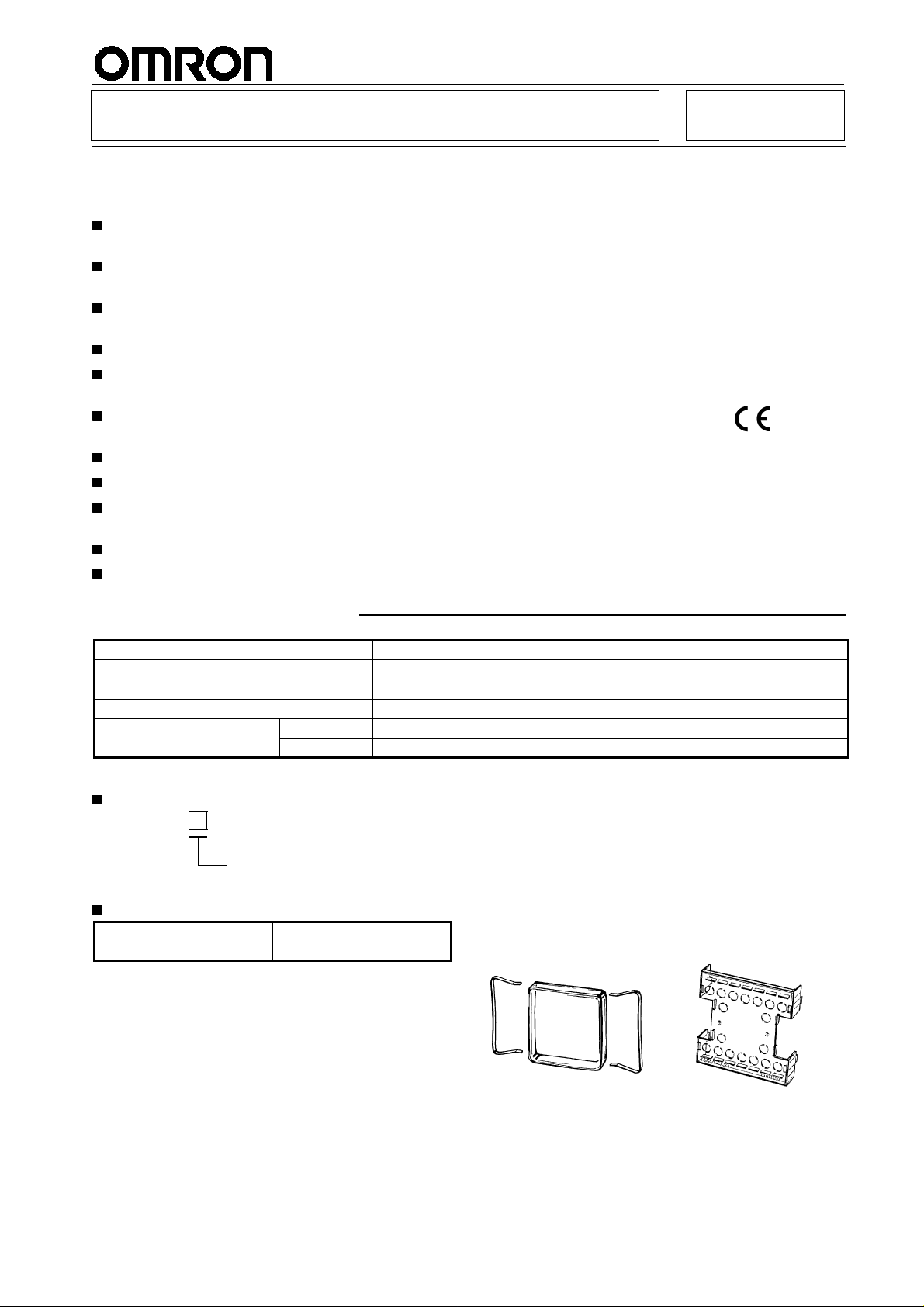
Multifunction Digital Timer H5BR
72 x72 mm Timer with Easy-to-use
Functions
Nine output modes accommodate a wide variety of
applications.
All parameters set by scroll-through menus
accessed from the front panel.
Field-selectable time ranges from 0.001 second to
9999 hours.
High visibility LCD display with built-in backlight.
Batch counting Function records the number of
completedcycles.
Contact and solid-state outputs available simulta-
neously.
Precision control possible to 0.001 second.
Four levels of key protection provided.
Selectable elapsed time (UP) and remaining time
(DOWN) display.
Conforms to EMC standards.
Six-language instruction manual provided.
RC
Ordering Information
Functions
Contact type
Terminal form
Part number
Supply voltage AC
DC
Specify both the model and control power supply when ordering.
Note:
Model Legend
H5BR -
T ype classifier
B: Standard
Accessories (Order Separately)
Soft cover Y92A-72F1
Shock prevention cover* Y92A-72T
Models with a shock prevention cover can be ordered by
Note:
adding “-500” to the end of the model number.
e.g., H5BR-B-500 (100 to 240 VAC, 50/60 Hz)
The cover provides finger protection conforming to
VDE0106/P100.
9 field selectable
One SPDT relay and two NPN open collector transfor output
18 terminal screws on rear of case
H5BR-B
24/100 to 240 V, 50/60 Hz
12 to 24 V
Soft cover
Shock Prevention Cover
(conforming to VDE0106/P100)
Y92A-72F1
Y92A-72T
1
Page 2
H5BR
Specifications
H5BR
Model
Classification
Mounting
External connections
Enclosure ratings
EMC
Approved standards
Display modes
Output modes
Reset system
Batch counting function
Sensor power supply
Input signals
Input method
Control outputs
Batch outputs
Display
Digits
Max. time settings
Memory backup
H5BR-B (Standard type)
Digital timer
Flush mounting
Screw terminals
IP54 (panel surface)
Emission Enclosure: EN55011 Group 1 class A
Emission AC Mains: EN55011 Group 1 class A
Immunity ESD: IEC801-2: 4 kV contact discharge (level 2)
8 kV air discharge (level 3)
Immunity RF-interference: ENV50140: 10 V/m (80 MHz to 1 GHz) (level 3)
Immunity Conducted Disturbance: ENV50141: 10 V (0.15 to 80 MHz) (level 3)
Immunity Burst: IEC801-4: 2 kV power-line (level 3)
2 kV I/O signal-line (level 4)
UL: File no. E41515
CSA: File no. LR22310
Conforms to EN50081-2, prEN50082-2
Elapsed time (UP), remaining time (DOWN)
A, A-1, A-2, A-3, b, b-1, d, E, F
Power reset (except A-3, b-1, and F modes), External, manual, automatic resets
(internal according to A-1, b, b-1, d, and E mode operation)
Yes
12 VDC
Start, reset, gate, batch count reset, key protect inputs
No-voltage input: Via opening and closing of contact
SPDT contact output and transistor output (NPN open collector)
Transistor output (NPN open collector)
LCD backlit
4 digits
9.999 s (0.001 s units), 99.99 s (0.01 s units), 999.9 s (0.1 s unit), 9999 s (1 s unit),
99 min 59 s (1 s unit), 999.9 min (0.1 min unit), 9999 min (1 min unit), 99 hr 59 min
(1 min unit), 999.9 hr (0.1 hr unit), 9999 hr (1 hr unit)
Backup time for power interruption: Approx. 10 years at 20!C
2
Page 3
H5BR
Ratings
Rated supply voltage
Operating voltage range
Power consumption
Reset and control signals
Batch count reset and gate
Key protect
One-shot time
Power reset (except A-3, b-1, and F mode)
Signal, reset, gate, batch count reset inputs
Key protect input
Control outputs
External power supply
Ambient temperature
Storage temperature
Ambient humidity
Case
H5BR
100 to 240 VAC, 50/60 Hz
24 VAC/12 to 24 VDC (permissible ripple: 20% max.)
85% to 110% of rated voltage
Approx. 8 VA at 50 Hz, 240 VAC; approx. 5 W at 24 VDC
Min. pulse width 1 ms/20ms selectable
Min. pulse width: Approx. 20 ms
Response time: 1 s
0.1 to 99.9 s or hold
Min. power opening time: 0.5 s
No-voltage input
ON impedance: 1 k"max. (Approx. 2 mA when 0")
ON residual voltage:2 V max.
OFF impedance: 100 k"min.
No-voltage input
ON impedance: 1 k"max. (Approx. 2 mA when 0")
ON residual voltage: 1 V max.
OFF impedance: 100 k"min.
Contacts: 5 A at 250 VAC, resistance load (cos#=1)
Transistor output: Open collector 100mA at 30 VDC max. residual voltage 2 V
max. (Approx. 1 V)
80 mA, 12 VDC$10% (5% ripple max.)
-10!Cto55!C (with no icing)
-25!Cto65!C (with no icing)
35% to 85%
Light gray
Characteristics
Repeat accuracy, setting error (including
temperature and voltage effects)
Insulation resistance
Dielectric strength
Impulse withstand voltage
Noise i mmunity
Static immunity
Vibration Destruction
Malfunction
Shock Destruction
Malfunction
Life expectancy Mechanical
Electrical
Weight
Power start:$0.01%$0.05 s max.
Control signal start:$0.005%$0.03 s max. *(rate for set value)
100 M"min. (at 500 VDC) (between current-carrying terminal and exposed
non-current-carrying metal parts, and between non-continuous contacts)
2,000 VAC, 50/60 Hz for 1 min (between current-carrying terminal and
exposed non-current-carrying metal parts) for 100 to 240 VAC type
1,000 VAC for 24VAC/12 to 24 VDC type
3 kV (between power terminals) for 100 to 240 VAC type, 1 kV for 24 VAC/12 to
24 VDC type
4.5 kV (between current-carrying terminal and exposed non-current-carrying
metal parts) for 100 to 240 VAC type, 1.5 kV for 24 VAC/12 to 24 VDC type
2 kV (between power terminals) and$600 V (between input terminals),
$
square-wave noise by noise simulator (pulse width: 100 ns/1%s, 1-ns rise)
Malfunction: 8 kV; destruction: 15 kV
10 to 55 Hz with 0.75-mm single amplitude each in three directions
10 to 55 Hz with 0.5-mm single amplitude each in three directions
294 m/s2(30G) each in three directions
98 m/s2(10G) each in three directions
10 million operations min.
100,000 operations min. (5 A at 250 VAC in load resistance)
Approx. 270 g (9.6 oz)
3
Page 4
H5BR
Nomenclature
H5BR
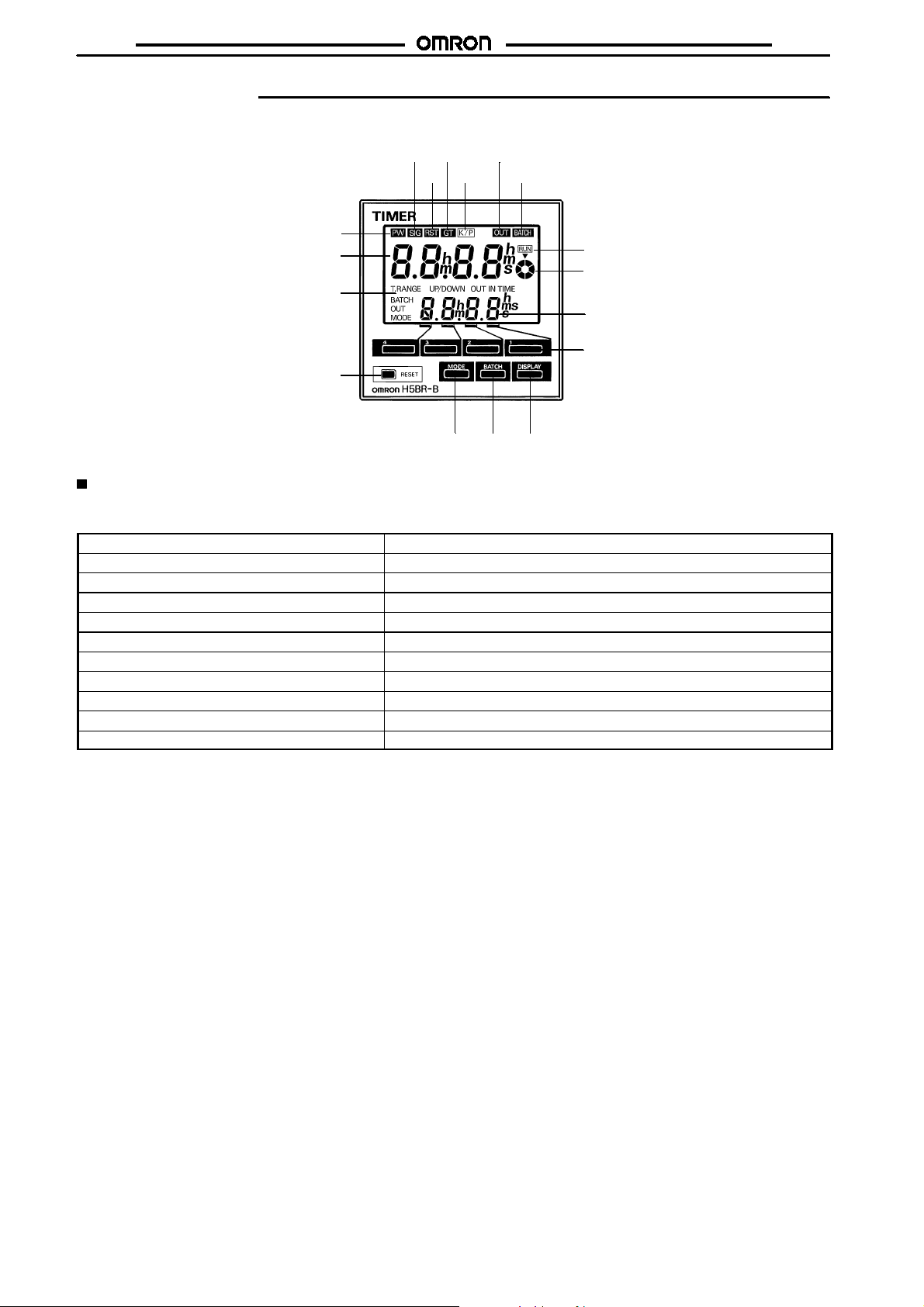
Display
1. Power indicator
2. Signal input indicator
3. Reset indicator
4. Gate indicator
5. Key protection indicator
6. Control output indicator
7. Batch output indicator
8. Present value
(character height: 12mm) (Non
significant zeroes suppressed)
9. Set value
(character height: 8 mm)
(Indicates value in set function mode)
10.Mode indicator
11. Timing indicator
12.Elapsed time indicator
(Indicates the fraction of a unit which
has elapsed. Displayed for timing
ranges of 999.9 min. or greater.)
24 6
35 7
1
8
10
17
15 1416
Operation key
13.Increment keys (1 to 4)
(Used to change the
corresponding digit of the set
value. Used to change data in the
setting mode.)
14.Display key
(Switches to the present value
11
display.)
12
15.Batch key
(Switches to the batch display.)
9
16.Mode key
(Switches from run mode to
setting mode. Changes items in
13
the setting mode.
17.Reset key
(Resets timing and outputs.)
Factory Settings
Thefollowing table shows thetimer settings whenitis shipped. Pleasechange the settings as necessary tosuit the systembeforeoperation.
Settings and the display receive power from the internal battery and are therefore unaffected by external power interruptions.
Model
Time range
Present value
Presets
Batch present count
Batch setting count
UP/DOWN mode
Output mode
Output time
Input signal time
Key protect level
With the initial settings, there will be no output even if the power supply is connected. External inputs and outputs cannot be used
Note:
without a power supply.
H5BR-B (Standard)
--.--s
0.00 s
0.00 s
0
0
UP
A: Signal on delay (I)
Hold
20 ms
KP-1
4
Page 5
H5BR
Operation
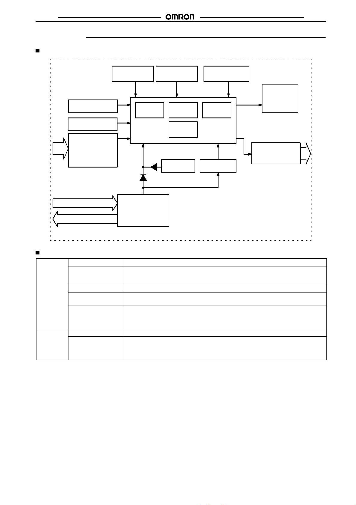
Block Diagram
H5BR
LCD drive
clock generator
Setting circuit
Key switch circuits
Input circuits (Reset, control signal,
batch count reset,
key protect, gate)
AC (DC) input
Power circuits *
External power supply
* Power supply is insulated from I/O.
ROM
System clock
generator
RAM
Control
circuits
Battery
LCD reference
voltage generator
LCDs
LCD driver
One-chip
microcomputer
Output circuits
(OUT, batch output)
Power outage
detector
I/O Functions
Inputs Start signal
Reset
Gate
Batch count reset
Key protect
Outputs Control output (OUT)
Batch output
Stops timing in A-2 and A-3 (power on delay) modes. Starts timing in other modes.
Resets present value. (to zero in UP modes, to preset in DOWN mode.
Count inputs are not accepted while reset input is ON.
Reset indicator lit while reset input is ON.
Inhibits timer operation.
Resets batch count to zero and batch output turns OFF on leading edge.
Batch count signals are not accepted while batch count reset is ON.
Makes keys inoperative according to key protect level.
Key protected indicator lit while key protect input is ON.
Effective when power supply is turned off.
Effective when protect terminals are shorted.
Outputs made according to designated output mode when corresponding preset is reached.
Outputs made when batch count equals the preset number of batches.
Batch output remains ON until batch count reset goes ON.
When the number of batches is set to zero, batch counting is performed but batch outputs are
not made.
5
Page 6

H5BR
Operational Overview
Run mode
Present value,
set value
Press the
DISPLAY key
Batch count value,
set value
Press the
BATCH key
Press the
MODE key
Press the
DISPLAY key
Setting mode
Press the
MODE key
Timing range
UP/DOWN mode
Output mode
Output time
Input signal time
Press the
MODE key
Press the
MODE key
Press the
MODE key
Press the
MODE key
H5BR
Note: 1. Set values are changed using the increment keys
(1 to 4).
2. The large arrows indicate the parameter displayed first
when the mode is changed with the MODE or DISPLAY
key.
Key protect level
Press the
MODE key
6
Page 7

H5BR
S
Setting Item Table
Mode Setting item Discription Setting procedure
Run mode Set value Compared to the present value.
Batch count set
value
Setting mode Time range* Determines the timing range.
UP/DOWN mode Selects
Determines the timing of the
control output according to the
output mode.
Turns ON the batch output when
the preset number of cycles have
been completed.
Sequence when changing a digit using the increment
keys (1 to 4).
012 89
Sequence when changing a digit using the increment
keys (1 to 4).
012 89
Change the timing range with the increment keys (1 to 4).
Select UP/DOWN with the increment keys (1 to 4).
(UP) (DOWN)
ud
H5BR
Output mode Determines the form of the control
output. (Refer to the present value
vs. output diagrams on page 10 to
12.)
Output time Determines the duration of the
control output.
Will be displayed when the output
mode is A, A-1, A-2, A-3, b, or
b-1. Will not be displayed when
the output mode is d, E, or F.
Input signal time Changes the duration of the
control and reset input signals.
Key protect level Locks certain keys to prevent
accidental operation. The key
protection level, kP-1 to kP-4,
determines which keys are locked
when the key protection input is
ON. The locked keys are crossed
out in the diagram on the right.
equence when changing themodeusing theincrement
keys (1 to 4).
a a-1 a-2 a-3 b b-1 d e f
Use keys 1 to 3 to change the value.
Key1 adjusts the first digit (0.1’s digit).
Key2 adjusts the second digit (1’s digit).
Key3 adjusts the third digit (10’s digit).
012 89
Key4 selects either hold output or one-shot output.
hold 0 0
Change the duration with the increment keys (1 to 4).
(1 ms) (20 ms)
120
Sequence when changing the key protect level using the
increment keys (1 to 4).
p
<KP--1> <KP--2>
p p p
.s
412 3
<KP--3><KP--3>
1. Changes made in setting mode become effective when run mode is entered.
Note:
2. The time range setting appears first when setting mode is entered.
7
Page 8

H5BR
Examples
Run Mode
Changing the Set Value
Tochange the set value from3hr5 min to 4hr5min, pressthe3key
so that the number 4 appears in the hour’s place.
&
Pressing keys 1 through 4 increments the corresponding
column by 1.
&
Thecolumns can be changedin any order,but the output will
be turned ON if the set value is less than the present value.
&
Nonsignificant zeros are normally not shownonthesetvalue
display.
H5BR
Changing the Batch Count Set Value
1. PresstheBATCHkeytoswitch fromthepresentvaluedisplay to
the batch count display.
2. Change the set value when the Timer is set to the batch count
display.
&
Nonsignificant zeros are normally suppressed on the batch
count set value display.
&
Press the DISPLAY key to switch back from the batch count
display to the present value display.
Read
Note:
Changing Set Values
15, before changing the Timer set value during operation.
inthe
Precautions
section, pg.
8
Page 9

H5BR
Setting Mode
Changing Settings in the Setting Mode
1. Press the MODE key to switch from run mode to setting mode.
&
The Timer will continue operation if switched from run mode
to setting mode during operation.
&
TheMODE key will be lockedif the key protection function is
enabled.
&
Settings changed in the setting mode are not effective until
runmode is entered. As the operating conditions willchange
in this case, always reset operation with the RESET key or a
reset input.
2. Press the MODE key to scroll successively through the items
that can be set.
H5BR
3. Changing the selected item
&
Press the MODE key until the desired item appears.
&
Changetheitemsetting by pressing keys 1 through 4. (Press
the DISPLAY key to switch back from setting mode to run
mode.)
9
Page 10

H5BR
Timing Charts
Output mode A: Signal ON delay 1 (Timer resets when power comes on.)
Power
Start signal
Gate
Reset
Control output
Set value
Timing
diagram
Output mode A-1: Signal ON delay 2 (Timer resets when power comes on.)
Timing
diagram
Output mode A-2: Power ON delay 1 (Timer resets when power comes on.)
Timing
diagram
Output mode A-3: Power ON delay 2 (Timer does not reset when power comes on.)
Timing
diagram
UP
DOWN
Start signal
Control output
Set value
UP
Set value
DOWN
Start signal
Control output
Set value
UP
Set value
DOWN
Start signal
Control output
Set value
UP
Set value
DOWN
0
Set value
0
Power
Gate
Reset
0
0
Power
Gate
Reset
0
0
Power
Gate
Reset
0
0
tt
t
t
t t at-a
H5BR
Timing begins at the leading edge of
the start signal. The control output will
be energized when the present value
equals the preset time. The output can
be sustained until a reset signal is
applied or power interrupted or for a
programmable one-shot time period.
Timing begins at the leading edge of
the start signal. The control output will
be energized if the start signal is
sustained for a amount of time equal
to the preset time. The output can be
sustained until a reset signal is
applied or power interrupted or for a
programmable one-shot time period.
Timing begins when power is applied.
Start signals act as a gate input
causing the present value to ???. The
control output will be energized when
the present value equals the preset
time. The output can be sustained
until a reset signal is applied or power
interrupted or for a programmable
one-shot time period.
10
One-shot
Sustained output
One-shot outputs can be set from 0.1 s to 99.9 s.
Page 11

H5BR
Output mode b: Repeat cycle 1 (Timer resets when power comes on.)
Power
Start signal
Gate
Reset
Control output
Set value
Timing
diagram
Timing
diagram
Output mode b-1: Repeat cycle 2 (Timer does not reset when power comes on.)
UP
Set value
DOWN
Start signal
Control output
Set value
UP
Set value
DOWN
Start signal
Power
Gate
Reset
Power
Gate
Reset
0
0
tt
0
0
H5BR
The OFF/ON cycle is initiated at the
leading edge of the start signal. The
output relay will be OFF for the preset
time, then ON for the preset time. The
cycle will be repeated until a reset
input is applied or power is
interrupted.
The OFF/ON cycle is initiated at the
leading edge of the start signal. The
control output will be OFF for the first
cycle. In subsequent cycles the output
will be ON for the programmable
one-shot time period, then OFF for the
remainedof the preset time. The cycle
will be repeated until a reset input is
applied or power is interrupted.
The OFF/ON cycle is initiated at the
leading edge of the start signal. The
output relay will be OFF for the preset
time, then ON for the preset time. The
cycle will be repeated until a reset
input is applied or power is
interrupted.
Timing
diagram
Timing
diagram
Control output
Set value
UP
Set value
DOWN
Power
Start signal
Gate
Reset
Control output
Set value
UP
Set value
DOWN
0
0
The OFF/ON cycle is initiated at the
leading edge of the start signal. The
control output will be OFF for the first
cycle. In subsequent cycles the output
will be ON for the programmable
one-shot time period, then OFF for the
remainedof the preset time. The cycle
tt t tt-aa
0
0
Sustained output
One-shot outputs can be set from 0.1 s to 99.9 s.
One-shot
will be repeated until a reset input is
applied or power is interrupted.
11
Page 12

H5BR
Output mode d: Signal OFF delay (Timer resets when power comes on.)
Power
Start signal
Gate
Reset
Control output
Set value
Timing
diagram
Output mode E: Interval (Timer resets when power comes on.)
Timing
diagram
Output mode F: Cumulative (Timer does not reset when power comes on.)
UP
DOWN
Start signal
Control output
UP
DOWN
Start signal
0
Set value
0
Power
Gate
Reset
Set value
0
Set value
0
Power
Gate
Reset
H5BR
The control output is energized at the
leading edge of the start signal.
Timing begins at the trailing edge of
the start signal. The control output is
de-energized when the present value
equals the preset time.
Timing begins on the leading edge of
the start signal. The control output is
only energized during timing. The
timer is reset when power is
interrupted or a reset signal is applied.
Timing begins on the leading edge of
the start signal. The control output is
energized when the cumulative
elapsed time of the start signal is
equal to the preset time. The output is
sustained until power is interrupted or
a reset signal applied.
Control output
Set value
Timing
diagram
UP
DOWN
0
Set value
0
Batch Counter Operation
Batch count reset
Batch count
Batch count pres-
Batch output
1. The batch count present value remains at 0 while the batch
count reset is ON.
2. When the batch count set value is 0, the batch count will
proceed, but there will be no output.
3. When the batchcountpresentvalueexceeds 9999, it returns
to 0.
4. The batchcountpresent value and output are not affectedby
RESET key or reset input.
5. When power is interruptedandthe batch countoutput is ON,
the output will be ON when power returns.
6. When a batch count set value which is greater than the
present value is changed to asetvalue which is less thanthe
present value, the output will go ON.
set
value
ent
value 0
The batch count output holds until
reset by the batch count reset.
The present value of the batch count
advances continuously.
7. If,aftertheoutput has goneON,the set value is changed toa
set value which is greater than the present value, the output
will remain ON.
8. In the Flicker 1, 2 output hold modes, the number of
completed timing is double the number ofoutputs. Tocontrol
thenumber ofoutputs,setthebatchcount set value atdouble
the desired number of outputs.
12
Page 13

H5BR
Dimensions
All units are in millimeters unless otherwise indicated.
Note:
H5BR
Flush Mounting
H5BR
72
6
100
M3.5 terminal screw
(effective length: 6 mm)
Flush Mounting Adaptor
Panel Cutouts
Panel cutouts are
as shown at right.
(according to DIN43700).
82 min.
72
67.6
Panel
1006
7 + panel thickness
100 min.
+0.7
68
-- 0
+0.7
68
-- 0
13
Page 14

H5BR
Installation
Terminal Arrangement
H5BR-B (Standard)
Contact and
Transistor outputs
Batch count reset
input
Key protect input
15
16
Common
0V
89
(-)
Reset input
Start signal input
Gate input
12 V
10 11 1312 14
External
power
supply
(+)
OUT
Batch
OUT
17
18
H5BR
Unused
Unused
Do not connect unused terminals.
Note:
2
(+)
(-)
6531
47
100 to 240 VAC/24 VAC
12 to 24 VDC
Connections
The inputs of the H5BR are no-voltage (short circuit or open) inputs.
No-contact Input
(NPN Transistor)
Sensor
Timer
12 VDC
Start signal,
reset, etc.
Input use 0 V
High: transistor ON
No-voltage Input Signal Levels
1. High level
Transistor ON
No-contact
input
Residual voltage: 2 V max.
Impedence when ON: 1 k"max.
2. Low level
Transistor OFF
Impedence when OFF: 100 k"min.
Contact
input
Use contacts which can adequately switch 2 mA at 5 V
Contact Input No-contact Input
Timer
Start signal,
reset, etc.
Input use 0 V
High: contact ON High: transistor ON
+V (30 V max.)
Sensor
Timer
12 VDC
Start signal,
reset, etc.
Input use 0 V
14
Page 15

H5BR
e
Precautions
H5BR
External Power Supply
&
The capacity of the external power supply is 80 mA at 12 VDC.
When using a 24 VAC/12 to 24 VDC power supply, reduce the
load with the power supply voltage, as shown in the following
diagram (DC power supplies only).
12 VDC output
1310 20
Load current (mA/DC)
80
20
0
Supply voltage (VDC)
Power Supplies
&
Ifpower isinterruptedforlessthan10 ms,operationwillcontinue
normally. If power is interrupted for between 10 and 500 ms,
operation will be inconsistent, and timing may stop or reset,
depending on the mode.
&
Connect the power supply voltage through a relay or switch in
such a way that the voltage reaches a fixed value immediately.
&
Dependingon switchingfrequency,currentsurgesmaydegrade
relay contacts; relays with a capacity greater than 10 A are
recommended.
&
Be sure that the capacity of the external power supply is
adequate, because the power supply may not provide a surge
currentsufficient to start the Timerduetotheswitchingregulator
contained in the Timer’s internal circuitry.
Input and Output
&
Do not use external sources to increase the voltage of input
signals (control signal, reset, gate, and key protection).
&
Be sure that the load of thecontrol output (contact, transistor) is
less than the maximum values indicated inthe specifications. If
theoutputloadexceedstherecommendedvalue,thelifespanof
the contact output type will be shortened dramatically, and the
transistor of the transistor output type will be damaged.
&
The transistor output is insulated from the internal circuitry by a
photocoupler, so either NPN or PNP transistors can be used.
Self-diagnostic Function
&
Thefollowingdisplayswillappearifanerroroccurs.Thepresent
value and output enter the same status as after pressing the
RESET key.
Display
e1
e2
Error Output
status
CPU OFF Press
Memory
Correction Setting
RESET k eyNochange
(batch count
to 0)
Setatthe
factory
Changing Set Values
&
TheTimer set valuecanbechangedwhilethetimerisoperating,
soahigh value canbesettemporarilytoinactivate thetimer,or a
lowvaluecanbesettoactivate the timer more quickly.(If the set
value is changed accidentally during operation, the timer might
beactivated. Therefore, turnthe key protectioninput ON unless
the set value is being changed.)
&
To avoid changing the output when changing the set value, it is
recommended to begin changing the set value by entering a
large number in the higher digit.
Operating Environment
&
When using the Timer in an area with much electronic noise,
separate the Timer,wiring, and the equipment which generates
the input signals as far as possible from the noise sources. It is
also recommended to shield the input signal wiring to prevent
electronic interference.
&
Organicsolvents(suchas paint thinner), aswellasvery acidicor
basic solutions might damage the outer casing of the Timer.
Other
&
When the timer is installed in a control box and tests are
conducted which may damage the Timer’s internal circuitry (for
example, a test measuring the maximum voltage difference
between the control circuit and metal components), remove the
Timer from the control box or short circuit the terminals.
Caution
!
This product contains a lithium battery. Lithium batteries explodeifincinerated.Disposeof theDigitalTimerasanon-combustible item.
ALL DIMENSIONS SHOWN ARE IN MILLIMETERS.
To convert millimeters into inches, multiply by 0.03937. To convert grams into ounces, multiply by 0.03527.
Cat. No. L034-E1-2B
In the interest of product improvement, specifications are subject to change without notic
OMRON Corporation
Systems Components Division
28th Fl., Crystal Tower Bldg.
1-2-27, Shiromi, Chuo-ku,
Osaka 540 Japan
Phone: 06-949-6012 Fax: 06-949-6021
Printed in Japan
0697-0.5M (0696)
a
15
 Loading...