

Page 1
Digital Timer H5AN
g
(
integrating operation
(excluding -M)
0.01 to 99.99 s, 0.1 to 999.9 s, 1 to
DIN-sized (72 x 72 mm) Quartz Timer
with Multiple Functions
Wide time range from 1/100 seconds to 9999 hrs.
Built-in
direct connection of sensors and other components.
Draw-out
disconnecting the wiring.
Power supply freely selectable within a range of
100 to 240 VAC; a DC-operated version is also
available.
Control
type simultaneously available.
Seven
available.
Ordering Information
power supply incorporated
in timer enables
construction allows maintenance without
outputs of both contact type and
operating modes (N, F
, C, R, K, P
solid-state
, and Q) are
RC
Operation
T
ime-limit operation,
inte
Note: 1.
system
rating operation
Specify both the model number and supply voltage when ordering.
2.
The T
Resetting system
Power-OFF resetting
excluding -M),
external resetting,
manual resetting,
automatic resetting
imer is supplied with two mounting fixtures.
,
4 digits (switch-selectable):
0.01 to 99.99 s, 0.1 to 999.9 s, 1 to
9999 s, 0.1 to 999.9 min, 0.1 to 999.9 hrs,
1 to 9999 hrs, 1 s to 99 min 59 s,
1 min to 99 hrs 59 min
No. of digits
Backup power
supply function for
memory protection
Not provided
Provided (approx.
10 years at 20
°C)
Model
H5AN-4D
H5AN-4DM
1
Page 2
H5AN
Specifications
Ratings
Item H5AN-4D/H5AN-4DM
Rated
supply voltage
Operating voltage range
Power consumption
Resetting system and
gate input
One-shot output time
Control outputs
Power supply for
externally connected
components
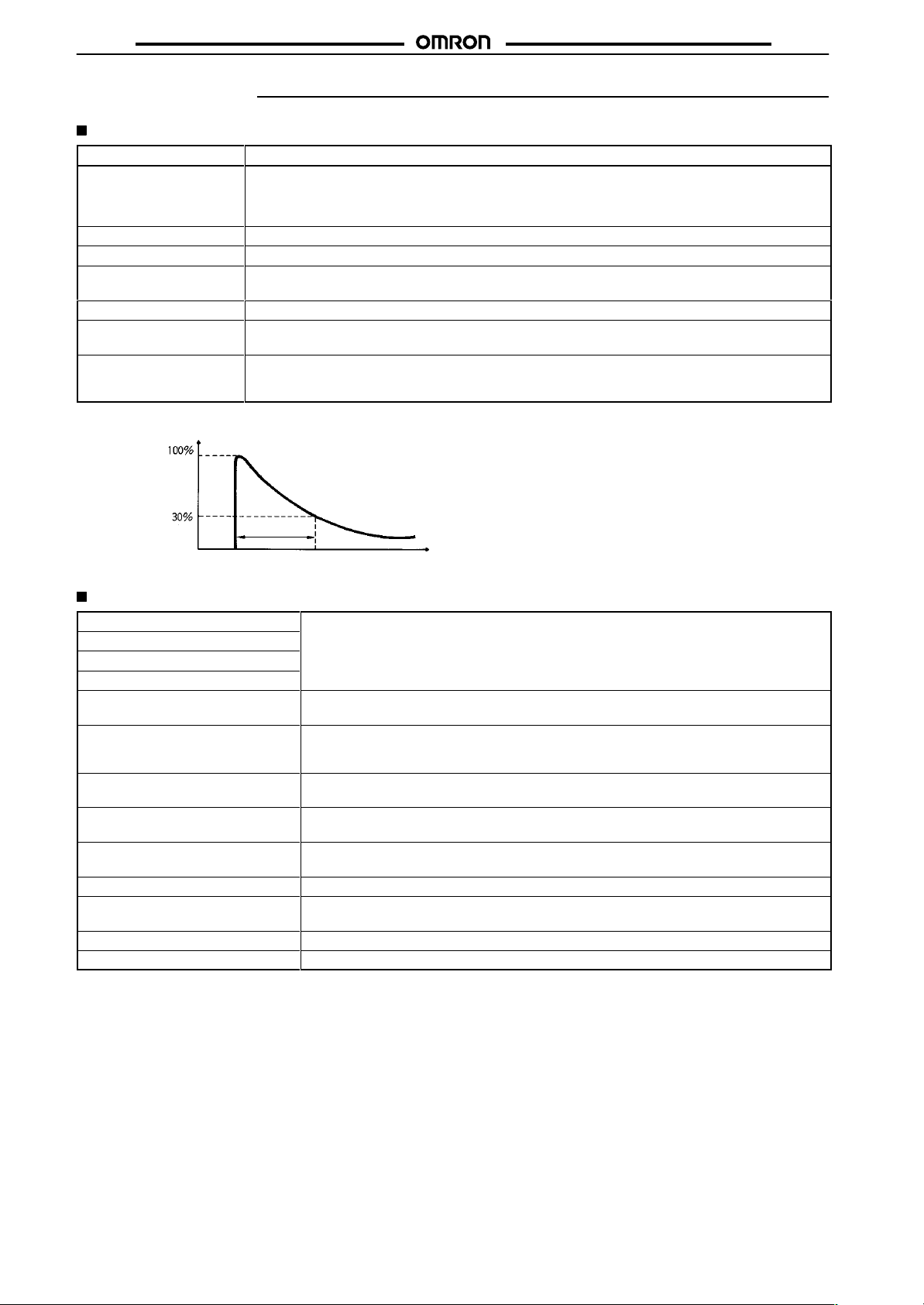
Note:
Inrush current was measured within the range shown below
Peak value
H5AN-4D:
H5AN-4DM:
85% to 1
Approx. 10 V
Reset by power-OFF: min. power OFF time: 0.5 s
External reset or gate (common to contact and solid-state inputs): min. reset input signal width: 0.02 s
0.1 to 1 s (adjustable)
Contact output: SPDT
Solid-state output: Open collector
12 VDC±
100 to 240 V
12 to 24, 48, or 100 VDC (permissible ripple: 20% max.)
100 to 240 V
12 to 24 VDC (permissible ripple: 20% max.)
10% of rated supply voltage
A (at 240 V
10%, 80 mA (permissible ripple: 5% max.)
AC (50/60 Hz),
AC (50/60 Hz)
AC, 50 Hz), approx. 5 W (at 24 VDC)
, 3 A at 250 V
AC, resistive load (cosφ
, 100 mA max. at 30 VDC max.
.
H5AN
= 1)
Measurement
Inrush current
time
Time
Characteristics
Accuracy
Setting error
Influence of voltage
Influence of temperature
Insulation resistance
Dielectric strength
V
ibration resistance
Shock resistance
Ambient temperature
Ambient humidity
Life expectancy
Approved standards
Weight
Note:
of operating time
This value denotes the average of the repeat accuracy
cludes the rise time of the power supply
±
0.01% ±0.05 s max. (power OFF start), ±0.005% ±0.03 s max. (reset start) (see note)
100 MΩ min. (at 500 VDC) (between current-carrying terminal and exposed non-current
carrying metal parts, between non-continuous contacts)
2,000 V
parts)
750 V
Destruction:
Malfunction:
Destruction:
Malfunction:
Operating: –10°
Storage: –25°
Operating: 35% to 85%
Mechanical:
Electrical:
UL (File No. E41515), CSA (File No. LR22310)
Approx. 360 g
AC, 50/60 Hz for 1 min (between current-carrying and non-current-carrying metal
AC, 50/60 Hz for 1 min (between non-continuous contacts)
10 to 55 Hz with 0.75-mm double amplitude
10 to 55 Hz with 0.5-mm double amplitude
300 m/s2 (approx. 30G)
100 m/s2 (approx. 10G)
C to 55
°C
C to 65
°C
10,000,000 operations min. (under no load at 1,800 operations/h)
100,000 operations min. (3 A at 250 V
, and the operating time of the internal and output circuits.
, setting error
, and variations due to voltage and temperature changes. It in
AC, resistive load)
-
2
Page 3
H5AN
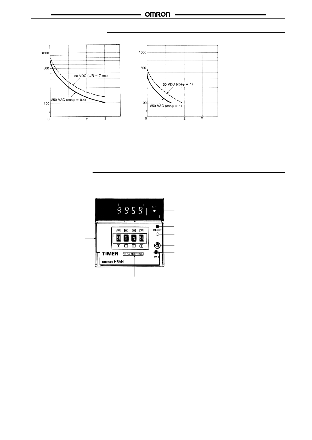
Engineering Data
H5AN
3
Switching operations (x 10 )
Load current (A)
Reference:
A maximum current of 0.15 A can be switched at 125 VDC (cosφ = 1).
Maximum current of 0.1 A can be switched if L/R is 7 ms. In both cases,
a life of 100,000 operations can be expected.
The minimum applicable load is 10 mA at 5 VDC (P reference value).
Nomenclature
7-segment
3
Switching operations (x 10 )
Load current (A)
LED display
Front cover
Rated time label af
(when a rated time label of
99 min 59 s is af
fixing section
fixed)
T
ime-up indicator
Reset input indicator
Pushbutton switch for manual reset
Internal unit fixing screw
One-shot time adjustment screw
3
Page 4
H5AN
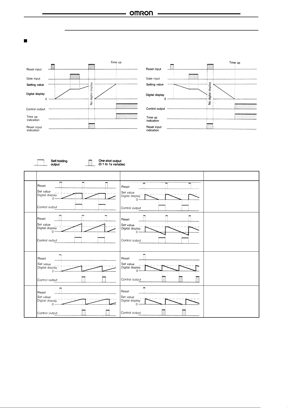
Operation
Timing Chart
Digital Display
UP Display DOWN Display
H5AN
Note:
After the set time has elapsed, operation continues according to the mode (N, F
Operation Mode
(The
control output and digital display when the set time is up dif
Mode UP
N
F
C
R
display
(See note)
(See note)
fer in each of the operation modes available.)
DOWN display
, C, R, K, P
, or Q).
Operation after the set time is
The control output and digital
display are held until a reset input
is applied.
In UP mode, the digital display
continues to increment up to
“9999” even after reaching the set
value and then returns to all
zeroes. In DOWN mode, the
digital display continues to up
9999, and then decrements “9998,
9997, ...,” after reaching all
zeroes. The control output is held
until a reset input is applied.
The digital display returns to the
initial setting once the set time has
elapsed and the timer restarts the
timing operation.
When the set time has elapsed,
the output signal is generated
during the one-shot time. The
timer repeats this cycle.
The digital display returns to the
initial setting after the one-shot
time and the timer restarts the
timing operation. When the set
time has elapsed, the output
signal is generated during the
one-shot time. The timer repeats
this cycle.
up
(See note)
(See note)
4
Page 5

H5AN
H5AN
Mode
K
P
Q
Note: 1. When
down)
2. In
this timing chart, the number of step advances during the one-shot time varies in accordance with the selected rated time and
duration
3.
In C and P modes, set time value n should be suf
UP display
a rated time of 99 min 59 s or 99
h 59 min is selected, the overflow values of the digital display when using the DOWN (count
DOWN display
function will be indicated as 9959, 9958, 9957, ... in modes F
of the one-shot time.
ficiently longer than the one-shot time t.
, K, and Q.
Operation after the set time is
In UP mode, the digital display
continues to increment up to
“9999”, even after reaching the set
value and then returns to all
zeroes. In DOWN mode, the
digital display continues up to
9999, and the decrements “9998,
9997, ...,” after reaching all
zeroes. The timer restarts the
timing operation when the
incrementing or decrementing
value reaches the set value.
The output is generated during the
one-shot time. The timer repeats
this cycle.
For the digital display
the up is held during the one-shot
time; however
operation of the timer returns to
the initial setting when the set time
has elapsed and the timer restarts
the timing operation. When the set
time has elapsed, the output
signal is generated during the
one-shot time. The timer repeats
this cycle.
In UP mode, the digital display
continues to increment after
reaching the set value during the
one-shot time. In DOWN mode,
the digital display continues to
9999 and then decrements “9998,
9997, ...,” after reaching all zeros
during the one-shot time.
However
modes, the digital display returns
to the initial setting after the
one-shot time and the timer
restarts the timing operation.
When the set time has elapsed,
the output signal is generated
during the one-shot time. The
timer repeats this cycle.
up
, the value at
, the timing
, in both UP and DOWN
-
5
Page 6

H5AN
Programming of Specifications
The
built-in
ming
level of the solid-state output when the set time has elapsed, etc.
Set
cations
lector Switches”.
specifications selector switches are used for program
UP or DOWN display
these switches for programming the
by referring to
, rated time, operation mode, and output
desired functional specifi
“Positions and Functions of Specification Se
H5AN
-
-
-
Open the front cover
The internal unit comes out by loosening
the internal unit fixing screw
.
.
6
Page 7

H5AN
iti
“0”
iti
“8”
Positions and Functions of Specification Selector Switches
SW3-1
Manual Reset Selector Switch
Enable
Disable
SW2 Operation Mode Selector Switch
SW1 T
ime Range Selector Switch
H5AN
SW3-2 Solid-state Output Level Selector Switch
H:
(Output level changes “low” to “high” when
the set time is up.)
L:
(Output level changes “high” to “low” when
the set time is up.)
SW1
Switch position
0
1
2
3
4
5
6
7
8
9
Note: Select
plied
as accessories, and af
the front panel.
the appropriate label, from the rated time labels sup
Rated time
99.99 s
999.9 s
9999 s
99 min 59 s
999.9 min 0.1 to 999.9 min
99 hrs 59 min
999.9 hrs
9999 hrs
99.99 s
999.9 s
Dimensions
Note: All
units are in millimeters unless otherwise indicated.
Setting range
0.01 to 99.99 s
0.1 to 999.9 s
1 to 9999 s
1 s to 99 min 59 s
1 min to 99 hrs 59 min
0.1 to 999.9 hrs
1 to 9999 hrs
Same as switch
position “0”
Same as switch
position “1”
fix it on the proper position on
Two mounting fixtures
M3.5 terminal screws
67.6 x 67.6
SW2
Switch position
0 N DOWN display
1 F
2 C
3 R
4 K
5 P
6 Q
7 N
8 N UP
9 F
A C
-
B R
C K
D P
E Q
F N
Panel Cutouts
(Panel cutout conforms
to DIN 43700)
Operating mode
(see note 1)
(see note 2)
Display mode
Note: 1. Same as
Note: 2. Same as
(Horizontally
N units)
{(n – 1) x 72 + 70 } min.
(including 2-mm clear
ance between units)
display
switch
pos
on
switch
pos
on
connecting
“
”
“
”
-
N
7
Page 8

H5AN
Installation
Terminal Arrangement
Reset input
Gate input
(Internally
connected)
(0 V)
External
power
supply
+12 V
+12 V
Contact output
H5AN
Note: Specifications for 12- to 24-VDC, 48-VDC, and 100-VDC
models are listed separately in this datasheet.
Unused
Power supply
For DC power
Terminal 1: –
Terminal 2: +
Connections
Power Supply Connection
Connect
the required supply voltage to terminals 1 and 2.
AC Power Supply DC Power Supply
Load Connection
Terminals
13
surge
The
multaneously
4,
are for solid-state output. (T
5, and 6 are for contact output while terminals 12 and
erminal 14 is connected to absorb the
if an inductive load is connected.)
control outputs of both
contact type and solid-state type are si
available.
Unused
Do not use unused
terminals for relaying.
Leave them open.
Load Operation
-
(See
note.)
Note: Output transistor ON: Low (0 V)
Output transistor OFF: High (12 V)
When
a Load Operates with Contact Output
Load 1
Load 2
When a Load Operates with Solid-state Output
(See
note.)
Load 3
Note: Connect
a diode when using a Power Supply of 12 V or less.
8
Page 9

H5AN
H5AN
Connection of Reset and Gate Inputs
For
reset input, connect a contact or an open
tor between terminals 8 and 9. The timer resets when contact is
made
or when the transistor is ON. For gate inputs,
tact
or an open collector type transistor between terminals 8 and 10.
The timer stops when contact is marked or when the transistor is
ON.
Use a contact of high contact reliability, or an open collector type
transistor with characteristics: V
voltage)
= 3 V max., IC = 50
0.5 µA max.. Use of a gate input contact with minimum contact
bounce
(chatter) is
an
error in timer operating time.
When
connecting a solid-state circuit not of the open collector type
to the gate or reset inputs as shown below
state
circuit (+V) should be 13 to 30 V
tor
should be less than 3 V (the current that flows from either termi
nal
9 or
10 is approximately 10 mA). Moreover
circuit be ON for gate or reset input, and OFF when there is no input.
a must, since the contact bounce time will cause
CEO
mA min. and I
collector type transis
= 20 V min., V
, and the V
(leakage current) =
CBO
, the voltage of the
CE(S)
, it is essential that the
connect a con
(residual
CE(S)
solid-
of the transis
-
-
-
-
Connection of a Power Supply for Externally
Connected Components
The
H5AN has a built-in power supply for externally connected com
ponents
such as sensors for gate or reset input, or loads
to
the solid-state control output (12 VDC, 80 mA).
Power can be applied to the sensors and loads simultaneously
(gate)
(reset)
connected
Load
Simultaneous Input to a Number of H5AN Timers with the Same Contact or the Same Open
Collector Transistor
A
reset or gate input may be applied to two or more units of H5AN
with
only one contact or transistor as shown below
tion
is required as a large current flows into the transistor
rent
that flows from H5AN is approximately 10 mA pre unit.)
. In this case,
. (The cur
cau
-
.
-
-
9
Page 10

H5AN
Precautions
H5AN
Setting of Operating Time
Time
Setting Range
Rated time
99.99 s
999.9 s
9999 s
99 min 59 s
999.9 min
99 hrs 59 min
999.9 hrs
9999 hrs
Note:
The decimal point is not shown in the digital display
1. Since
2. When
3. Since
Examples of Setting/Actual Operating T
the H5AN T
any time during normal operation, the set time can be
changed
output from the
quickens
operation, the set time may be accidentally changed by
touching
with a dif
front cover closed except when changing the set time.
there will be a momentary control output upon power
application
changing the set time during normal operation, pay special
attention
of 99 min 59 s or 99 hrs 59 min is
or
will be rated as 5. Some erroneous setting examples are
shown
during power application. This feature sets back the
timer
the output by setting the shorter time. During normal
a thumbwheel switch, causing the timer to operate
ferent set time. To prevent this possibility
the set time is all zeroes (e.g., 000.0 s or 00 hrs 00 min),
which can be used to check normal output. When
not to alter the set value to this state.
the sexagesimal system is adopted, when a rated time
more (i.e. 6-9) in the order of x 10 s or x 10 min respectively
below
.
0.01 to 99.99 s (see note)
0.1 to 999.9 s (see note)
1 to 9999 s
1 s to 99 min 59 s
0.1 to 999.9 min (see note)
1 min to 99 hrs 59 min
0.1 to 999.9 hrs (see note)
1 to 9999 hrs
imer is capable of reading the
by temporarily setting the longer time or
Setting range
selected,
ime
any value set to 6
.
input data at
, keep the
4. When
5. When
Note: If the timer is not reset, it operates in accordance with the
changing the set time while power is being supplied, an
inadequate
numbers in one digital display window
time to drift widely. Therefore, press the thumb-wheel
switches surely. Take particular care in the case when the
other
fourth switch to create four zeroes will cause a momentary
output.
(Undesirable Setting)
H5AN-4DM T
memory protection, it is necessary to reset (either
externally or manually) the timer at the time the power is
applied.
Also when this type of timer is connected to a device (or
manually) this must also be done when power is applied for
the first time.
previous specifications or with the factory set specifications.
push of the thumbwheel switches will display two
three digits are all zero, since the improper setting of the
(Possible
59 s
99 min
59 min
99 hrs
operating the built-in selector switches of the
imer with a backup power supply function for
, causing the operating
Operating T
5 min 30 s
00 h 00 min
(momentary
output)
ime)
10
Page 11

H5AN
H5AN
Resetting
Memory Protection
of T
ype with a Backup Power Supply Function for
Purchase of H5AN
Is the timer
equipped with
memory protec-
tion?
Selection of
specifications
Was the timer
reset after
power applica-
tion?
The timer operates according to the desired
specifications.
Specifications change in
the middle of operation.
Was the
timer
reset?
The timer operates according to the desired
specifications.
Yes
Yes
Yes
6. The
type without a backup power supply function for memory
protection operates as shown below depending on the
duration
of the power failure.
(A)
Power failure of 0.01 s max.
Drawn out the internal unit from
No
No
the case, or switch
off the power to
reset the timer.
The timer operates according to
the factory-set
specifications.
Note: The
timer starts in the initial setting
upon power recovery.
(B)
Power failure of 0.5 s min.
Note: The
timer
upon power recovery.
(C)
Power failure of 0.01 to 0.5 s.
Note:
Either (A) or (B)
starts in the initial setting
The type with a backup power supply function for memory protection restarts in the status preceding the power failure as shown in
(A),
regardless of the duration of the power failure.
The timer operates
according to the
No
previous specifications.
7. The type with backup power supply for memory protection
incorporates a battery for backup power supply which lasts
for about ten years of normal use, meaning data is retained
even during a power failure lasting ten years. (The battery
cannot
be replaced.)
8. When
using the timer in operation modes other than N and F
modes
(i.e., C, R, K, P
, and Q), the control output is available
for the one-shot time only. For this reason, adjust the
one-shot
on
time by rotating the one-shot time adjustment screw
the front panel (variable within a range to 0.1 to 1 s).
Mounting
A
Mounting Fixture is included with the H5AN. Mount the Unit using
the
Mounting Fixture so that the Unit is secure and does not
move
(Y92H-5)
Loosen (to the left) the
screws on the Mounting
Fixture sufficiently and
attach
it from the bottom.
Tighten (to the right) the
screws on the Mounting
Fixture completely.
When the screw is tightened
completely
, you
will
hear it turning freely in
place.
11
Page 12

H5AN
H5AN
A model is also available for vertical gang-mounting (Model
H5AN-4D(M)-300).
Label to cover holes
Fixture
Specifications label
Sunken nut
WARNING
!
Fire,
Explosion, and Severe Burn Hazard
The
H5AN has a built-in lithium battery
the
old H5AN properly
if
incinerated.
, as lithium
batteries are likely to explode
. Be sure to dispose of
ALL DIMENSIONS SHOWN ARE IN MILLIMETERS.
To
convert millimeters into inches, multiply by 0.03937. T
o convert grams into ounces, multiply by 0.03527.
Cat. No. L050-E1-7B In the interest of product improvement, specifications are subject to change without notice.
OMRON Corporation
Industrial
Measuring and Supervisory Controls Department
Shiokoji Horikawa, Shimogyo-ku,
Kyoto, 600-8530 Japan
Tel: (81)75-344-7108/Fax: (81)75-344-7189
12
Automation Company
Printed
in Japan
0301-0.5C (0696)
 Loading...