

Page 1
Solid-state Timer H3YN B-85
Timers
Solid-state Timer
H3YN
Miniature Timer with Multiple Time Ranges
and Multiple Operating Modes
• Minimizes stock.
• Pin configuration compatible with MY Power Relay.
• Standard multiple operating modes and multiple time ranges.
• Conforms to EN61812-1 and IEC60664-1 for Low Voltage, and
EMC Directives.
Model Number Structure
■ Model Number Legend
1. Output
2: DPDT
4: 4PDT
2. Time Range
None:Short-time range (0.1 s to 10 min)
1: Long-time range (0.1 min to 10 hrs)
3. Contact Type
None:Single contact
Z: Twin contacts
Ordering Information
■ List of Models
■ Accessories (Order Separately)
Connecting Socket
H3YN-@@-@
1 2 3
Supply voltage Time-limit contact Short-time range model
(0.1 s to 10 min)
Long-time range model
(0.1 min to 10 h)
24, 100 to 120, 200 to 230 VAC;
12, 24, 48, 100 to 110, 125 VDC
DPDT H3YN-2 H3YN-21
4PDT H3YN-4 H3YN-41
24 VDC 4PDT (Twin contacts) H3YN-4-Z H3YN-41-Z
Note: Specify both the model number and supply voltage when ordering.
Example: H3YN-2 24 VAC
Supply voltage
Timer Track mounting/Front
Connecting Socket
Back Connecting Socket
Solder terminal Wire-wrap terminal PC terminal
H3YN-2/-21 PYF08A, PYF08A-N,
PYF08A-E
PY08 PY08QN(2) PY08-02
H3YN-4/-41
H3YN-4-Z/-41-Z
PYF14A, PYF14A-N,
PYF14A-E
PY14 PY14QN(2) PY14-02
Page 2
B-86 Solid-state Timer H3YN
Hold-down Clips
Specifications
■ Ratings
Note: 1. Single-phase, full-wave-rectified power supplies can be used.
2. When using the H3YN continuously in any place where the ambient temperature is in a range of 45°C to 50°C, supply 90% to 110% of
the rated supply voltages (supply 95% to 110% with 12 VDC type).
3. Set the reset voltage as follows to ensure proper resetting.
100 to 120 VAC: 10 VAC max.
200 to 230 VAC: 20 VAC max.
100 to 110 VDC: 10 VDC max.
Model Applicable Socket
Y92H-3 PYF08A, PYF08A-N, PYF08A-E
PYF14A, PYF14A-N, PYF14A-E
Y92H-4 PY08, PY08QN(2), PY08-02
PY14, PY14QN(2), PY14-02
Item H3YN-2/-4/-4-Z H3YN-21/-41/-41-Z
Time ranges 0.1 s to 10 min (1 s, 10 s, 1 min, or 10 min max.
selectable)
0.1 min to 10 h (1 min, 10 min, 1 h, or 10 h max.
selectable)
Rated supply voltage 24, 100 to 120, 200 to 230 VAC (50/60 Hz)
12, 24, 48, 100 to 110, 125 VDC (see note 1)
Pin type Plug-in
Operating mode ON-delay, interval, flicker OFF start, or flicker ON start (selectable with DIP switch)
Operating voltage range 85% to 110% of rated supply voltage (12 VDC: 90% to 110% of rated supply voltage)
(see note 2)
Reset voltage 10% min. of rated supply voltage (see note 3)
Power consumption 100 to 120 VAC: Relay ON: approx. 1.8 VA (1.6 W) at 120 VAC, 60 Hz
Relay OFF: approx. 1 VA (0.6 W) at 120 VAC, 60 Hz
200 to 230 VAC: Relay ON: approx. 2.2 VA (1.8 W) at 230 VAC, 60 Hz
Relay OFF: approx. 1.5 VA (1.1 W) at 230 VAC, 60 Hz
24 VAC: Relay ON: approx. 1.8 VA (1.4 W) at 24 VAC, 60 Hz
Relay OFF: approx. 0.3 VA (0.2 W) at 24 VAC, 60 Hz
12 VDC: Relay ON: approx. 1.1 W at 12 VDC
Relay OFF: approx. 0.1 W at 12 VDC
24 VDC: Relay ON: approx. 1.1 W at 24 VDC
Relay OFF: approx. 0.1 W at 24 VDC
48 VDC: Relay ON: approx. 1.2 W at 48 VDC
Relay OFF: approx. 0.3 W at 48 VDC
100 to 110 VDC: Relay ON: approx. 1.6 W at 110 VDC
Relay OFF: approx. 0.4 W at 110 VDC
125 VDC: Relay ON: approx. 1.6 W at 125 VDC
Relay OFF: approx. 0.4 W at 125 VDC
Control outputs DPDT: 5 A at 250 VAC, resistive load (cosφ = 1)
4PDT: 3 A at 250 VAC, resistive load (cosφ = 1)
Page 3
Solid-state Timer H3YN B-87
Timers
■ Characteristics
Note: 1. Terminal screw sections are excluded.
2. Refer to the Life-test Curve.
Item H3YN-2/-21/-4/-41
Accuracy of operating time ±1% FS max. (1 s range: ±1%±10 ms max.)
Setting error ±10%±50 ms FS max.
Reset time Min. power-opening time: 0.1 s max. (including halfway reset)
Influence of voltage ±2% FS max.
Influence of temperature ±2% FS max.
Insulation resistance 100 MΩ min. (at 500 VDC)
Dielectric strength 2,000 VAC, 50/60 Hz for 1 min (between current-carrying terminals and exposed non-current-carrying
metal parts) (see note 1)
2,000 VAC, 50/60 Hz for 1 min (between operating power circuit and control output)
2,000 VAC, 50/60 Hz for 1 min (between different pole contacts; 2-pole model)
1,500 VAC, 50/60 Hz for 1 min (between different pole contacts; 4-pole model)
1,000 VAC, 50/60 Hz for 1 min (between non-continuous contacts)
Vibration resistance Destruction: 10 to 55 Hz, 0.75-mm single amplitude for 1 h each in 3 directions
Malfunction: 10 to 55 Hz, 0.5-mm single amplitude for 10 min each in 3 directions
Shock resistance
Destruction: 1,000 m/s
2
Malfunction: 100 m/s
2
Ambient temperature Operating: −10°C to 50°C (with no icing)
Storage: −25°C to 65°C (with no icing)
Ambient humidity Operating: 35% to 85%
Life expectancy Mechanical: 10,000,000 operations min. (under no load at 1,800 operations/h)
Electrical: DPDT:
500,000 operations min. (5 A at 250 VAC, resistive load at 1,800 operations/h)
4PDT:
200,000 operations min. (H3YN-4-Z/-41-Z: 100,000 operations min.)
(3 A at 250 VAC, resistive load at 1,800 operations/h) (see note 2)
Impulse withstand voltage Between power terminals:
3 kV for 100 to 120 VAC, 200 to 230 VAC, 100 to 110 VDC, 125 VDC
1 kV for 12 VDC, 24 VDC, 48 VDC, 24 VAC
Between exposed non-current-carrying metal parts:
4.5 kV for 100 to 120 VAC, 200 to 230 VAC, 100 to 110 VDC, 125 VDC
1.5 kV for 12 VDC, 24 VDC, 48 VDC, 24 VAC
Noise immunity ±1.5 kV, square-wave noise by noise simulator (pulse width: 100 ns/1 µs, 1-ns rise)
Static immunity Destruction: 8 kV
Malfunction: 4 kV
Degree of protection IP40
Weight Approx. 50 g
EMC (EMI) EN61812-1
Emission Enclosure: EN55011 Group 1 class A
Emission AC Mains: EN55011 Group 1 class A
(EMS) EN61812-1
Immunity ESD: EN61000-4-2: 8 kV air discharge (level 3)
Immunity RF-interference from AM Radio Waves:
EN61000-4-3: 10 V/m (80 MHz to 1 GHz) (level 3)
Immunity Burst: EN61000-4-4: 2 kV power-line (level 3)
2 kV I/O signal-line (level 4)
Immunity Surge: EN61000-4-5: 2 kV line to ground (level 3)
1 kV line to line (level 3)
Approved standards UL508, CSA C22.2 No. 14, Lloyds
Conforms to EN61812-1 and IEC60664-1. (2.5 kV/2 for H3YN-2/-21, 2.5 kV/1 for H3YN-4/-41, H3YN4-Z/-41-Z)
Output category according to EN60947-5-1.
Page 4
B-88 Solid-state Timer H3YN
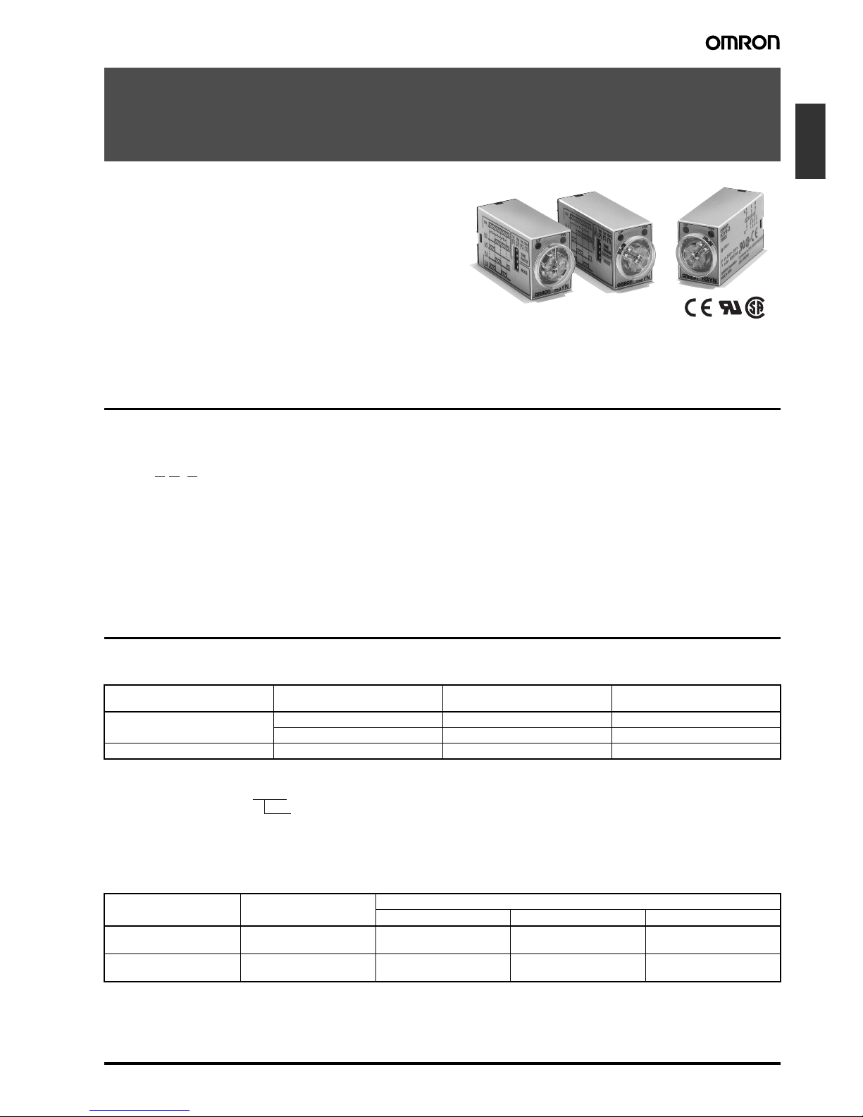
■ Life-test Curve (Reference Value)
5,000
1,000
500
200
5,000
1,000
500
200
5,000
1,000
500
200
5,000
1,000
500
200
5,000
1,000
500
100
60
H3YN-2/-21
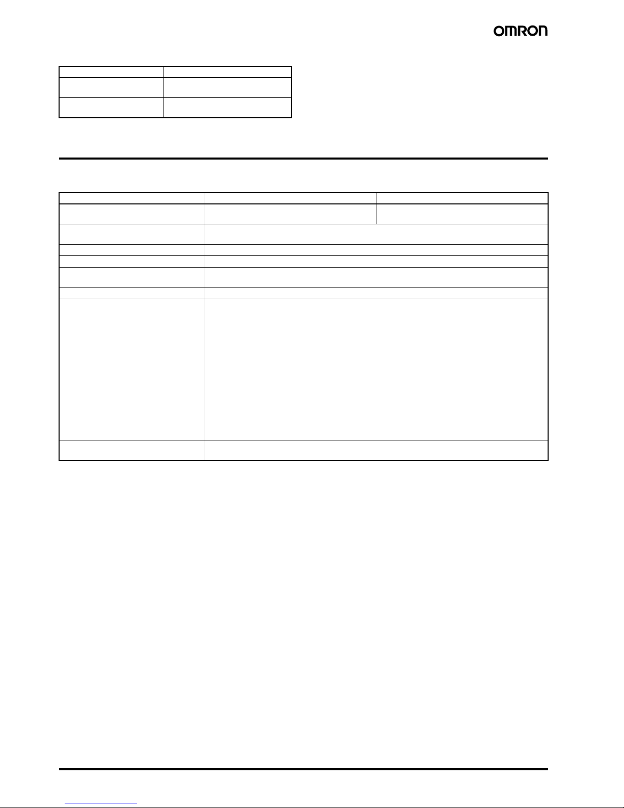
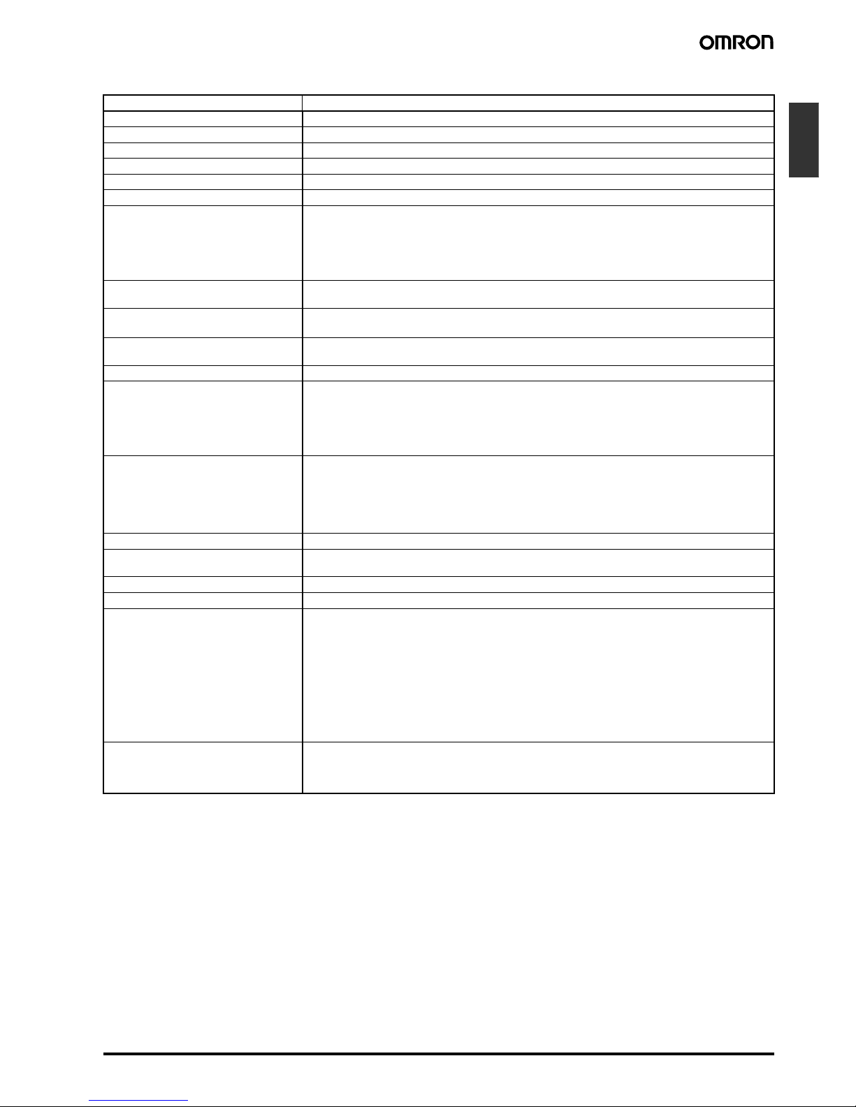
H3YN-4/-41
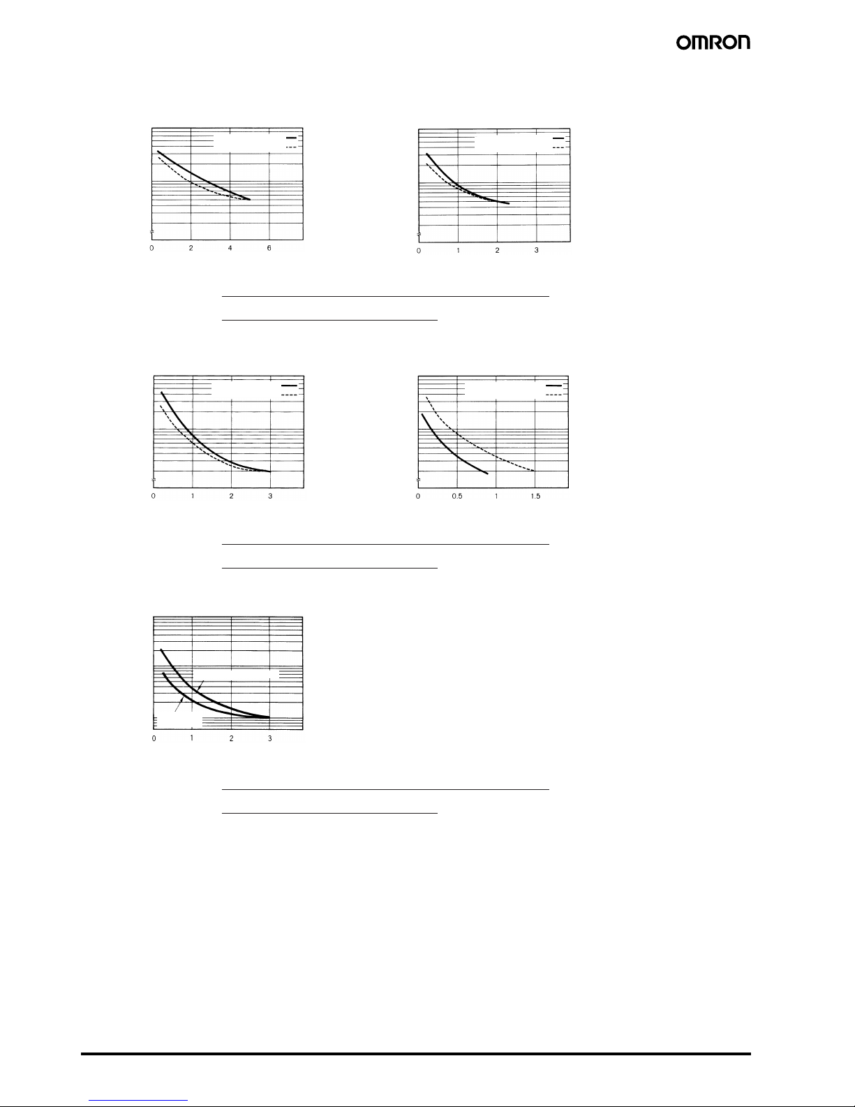
H3YN-4-Z/-41-Z
Switching operations (x 10
3
)
Load current (A)
Switching operations (x 10
3
)
Load current (A)
Switching operations (x 10
3
)
Load current (A)
Switching operations (x 10
3
)
Load current (A)
Switching operations (x 10
3
)
Load current (A)
250 VAC, resistive load
250 VAC, cosφ = 1
24 VDC, cosφ = 1
Reference: A maximum current of 0.6 A can be switched at 125 VDC (cosφ = 1).
Maximum current of 0.2 A can be switched if L/R is 7 ms. In both cases,
a life of 100,000 operations can be expected.
The minimum applicable load is 1 mA at 5 VDC (P reference value).
250 VAC, cosφ = 0.4
24 VDC, L/R = 7 ms
250 VAC, cosφ = 1
24 VDC, cosφ = 1
Reference: A maximum current of 0.5 A can be switched at 125 VDC (cosφ = 1).
Maximum current of 0.2 A can be switched if L/R is 7 ms. In both cases,
a life of 100,000 operations can be expected.
The minimum applicable load is 1 mA at 1 VDC (P reference value).
250 VAC, cosφ = 0.4
24 VDC, L/R = 7 ms
24 VDC, resistive load
Reference: A maximum current of 0.5 A can be switched at 125 VDC (cosφ = 1).
Maximum current of 0.2 A can be switched if L/R is 7 ms. In both cases,
a life of 100,000 operations can be expected.
The minimum applicable load is 0.1 mA at 1 VDC (P reference value).
Page 5

Solid-state Timer H3YN B-89
Timers
Connections
■ Connection
Pulse Operation
A pulse output for a certain period can be obtained with a random external input signal.
Use the H3YN in interval mode as shown in the following timing charts.
!Caution
Be careful when connecting wires.
UP PW
H3YN-2/-21
DIN Indication DIN Indication
UP PW
Timer
circuit
Timer
circuit
H3YN-4/-41
H3YN-4-Z/-41-Z
H3YN-2/-21
External input
Power (9-14)
Power (9-14)
External input
H3YN-4/-41
H3YN-4-Z/-41-Z
Timer
circuit
Timer
circuit
External short circuit
(5-13)
External input
(9-13)
Time limit contact
NO (12-8)
Time limit contact
NC (12-4)
Run/Power indicator
(PW)
Output indicator (UP)
50 ms
min.
Note: t: Set time
Rt: Reset time
External short circuit
(5-13)
External input
(9-13)
Time limit contact NO
(10-6, 11-7, 12-8)
Time limit contact NC
(10-2, 11-3, 12-4)
Run/Power indicator
(PW)
Output indicator (UP)
50 ms
min.
Note: t: Set time
Rt: Reset time
Mode Terminals
Pulse operation Power supply between 9 and 14
Short-circuit between 5 and 13
Input signal between 9 and 13
Operating mode; interval and all other modes Power supply between 13 and 14
Page 6

B-90 Solid-state Timer H3YN
Operation
■ Timing Chart
Note: t: Set time
Rt: Reset time
Operating mode Timing chart
H3YN-2/-21 H3YN-4/-41
ON-delay
Powe r
Output
Power (13-14)
Time limit contact
NC (9-1, 12-4)
Time limit contact
NO (9-5, 12-8)
Run/Power indicator
(PW)
Output indicator
(UP)
Power (13-14)
Time limit contact
NC (9-1, 10-2, 11-3,
12-4)
Time limit contact
NO (9-5, 10-6, 11-7,
12-8)
Run/Power indicator
(PW)
Output indicator
(UP)
Interval
Powe r
Output
Power (13-14)
Time limit contact
NC (9-1, 12-4)
Time limit contact
NO (9-5, 12-8)
Run/Power indicator (PW)
Output indicator
(UP)
Power (13-14)
Time limit contact
NC (9-1, 10-2, 11-3,
12-4)
Time limit contact
NO (9-5, 10-6, 11-7,
12-8)
Run/Power indicator (PW)
Output indicator
(UP)
Flicker OFF-start
Powe r
Output
Power (13-14)
Time limit contact
NC (9-1, 12-4)
Time limit contact
NO (9-5, 12-8)
Run/Power indicator
(PW)
Output indicator
(UP)
Power (13-14)
Time limit contact
NC (9-1, 10-2, 11-3,
12-4)
Time limit contact
NO (9-5, 10-6, 11-7,
12-8)
Run/Power indicator
(PW)
Output indicator
(UP)
Flicker ON-start
Powe r
Output
Power (13-14)
Time limit contact
NC (9-1, 12-4)
Time limit contact
NO (9-5, 12-8)
Run/Power indicator (PW)
Output indicator
(UP)
Power (13-14)
Time limit contact
NC (9-1, 10-2, 11-3,
12-4)
Time limit contact
NO (9-5, 10-6, 11-7,
12-8)
Run/Power indicator (PW)
Output indicator
(UP)
Page 7

Solid-state Timer H3YN B-91
Timers
■ DIP Switch Settings
The 1-s range and ON-delay mode for H3YN-2/-4/-4-Z, the 1-min range and ON-delay mode for H3YN-21/-41/-41-Z are factory-set before shipping.
Time Ranges
Note: The top two DIP switch pins are used to select the time ranges.
Operating Modes
Note: The bottom two DIP switch pins are used to select the operating mode.
Nomenclature
1 min 10 min1 s 10 s
Model Time range Time setting
range
Setting Factory-set
H3YN-2,
H3YN-4
H3YN-4-Z
1 s 0.1 to 1 s Yes
10 s 1 to 10 s No
1 min 0.1 to 1 min No
10 min 1 to 10 min No
H3YN-21,
H3YN-41
H3YN-41-Z
1 min 0.1 to 1 min Yes
10 min 1 to 10 min No
1 h 0.1 to 1 h No
10 h 1 to 10 h No
Operating mode Setting Factory-set
ON-delay Yes
Interval No
Flicker OFF-start No
Flicker ON-start No
Run/Power Indicator (Green)
(Lit: Power ON)
Output Indicator (Orange)
(Lit: Output ON)
Main Dial
Set the desired time according
to time range selectable by
DIP switch.
Page 8

B-92 Solid-state Timer H3YN
Dimensions
Note: All units are in millimeters unless otherwise indicated.
■ Timers
6.4
(63.0)
PY08 (PY14)
H3YN-2/-21 Front Mounting
Mounting Height
PY08 (PY14 (see note)) PY08QN (PY14QN (see note))
Note: Models in parentheses are Connecting Sockets to the H3YN-4/-41 or H3YN-4-Z/-41-Z.
Fourteen, 3 × 1.2 elliptic holes
28 max.
21.5 max.
28 max.
21.5 max.
Eight, 3 × 1.2 elliptic holes
PYF08A (PYF14A)
H3YN-4/-41 Front Mounting
H3YN-4-Z/-41-Z
PYF08A/PYF08A-N/PYF08A-E
(PYF14A/PYF14A-N/PYF14A-E
(see note))
H3YN
Series
H3YN
Series
H3YN
Series
PY08QN
(PY14QN)
Page 9

Solid-state Timer H3YN B-93
Timers
■ Accessories (Order Separately)
Connecting Sockets
Use the PYF@A, PY@, PY@-02, or PY@QN(2) to mount the H3YN. When ordering any one of these Sockets, replace “@” with “08” or “14.”
90.5
86.6
6
16.5
35.4
3.4
4
6
59±0.3
15±0.2
6
16.5
35.4
3.4
4
6
59±0.3
22±0.2
4421
8 5
12 9
14 14
13
441214
41 11
A2 A2 A1
19.8
4
42
8
44
1
12
5
14
41
12
A2
14
11
9
A113A2
14
PYF-08A-N
4 3 2 1
8 7 6 5
12 11 10 9
14 14
13
42 32 22 12
44 34 24 14
41 31 21 11
A2 A2 A1
20.8
4
42332222112
8447
34
6245
14
411231
11
211011
9
A1
13
A214A2
14
PYF-14A-N
PYF@A
Mounting Holes
72 max.
23 max.
30 max.
PYF-14A
Mounting Holes
72 max.
29.5 max.
30 max.
PYF-08A-N
Terminal Arrangement
3.2 dia.
3.6 dia.
22 max.
66.5 max.
30 max.
Two, 3.5 dia.
30 max.
66.5 max.
29.5 max.
PYF-14A-N
Terminal Arrangement
Track Mounting/Front Connecting Sockets
PYF08A
Two, 4.2 × 5
mounting holes
Eight, M3 ×
8 sems
Two, 4.5 dia.
M4 or M3
H3YN
Series
Two, 4.5 dia.
M4 or M3
Fourteen, M3 ×
8 sems
Two, 4.2 × 5
mounting holes
Terminal Arrangement
(Top View)
Terminal Arrangement
(Top View)
Mounting Holes
(for Surface Mounting)
Mounting Holes
(for Surface Mounting)
Page 10

B-94 Solid-state Timer H3YN
PYF08A-E
31 max.
72 max.
23 max.
(Top View)
PYF14A-E
31 max.
72 max.
29.5 max.
(Top View)
Two, 4.2 × 5
mounting holes
Eight, M3 ×
8 sems
Two, 4.5 dia.
M4 or M3
Two, 4.5 dia.
M4 or M3
Fourteen,
M3 × 8
sems
Two, 4.2 × 5
mounting holes
0.3
2.7 7.7
2.6
0.3
2.7
4.3
2
2.7
**
1 x 1
59.3
21.4
+0.2
0
25.8
+0.2
0
Panel Cutout
PY08-02, PY14-02
24 max.
20 max.
22 max.
16.5 max.
PY08@-02 PY14@-02
29.5 max.
25 max. *
24 max.
22 max.
PY08 PY14
Back Connecting Sockets
PY08, PY14
Eight, 3 × 1.2 dia. holes
only for PY08 (Fourteen, 3
× 1.2 dia. holes)
25.5
max.
29.5
max.
PY08QN, PY14QN
PY08QN(2), PY14QN(2)
Terminal Arrangement
(Bottom View)
Terminal Arrangement
(Bottom View)
H3YN
Series
PY@, PY@-02,
PY@QN(2)
PY14QN
PY14QN(2)
PY08QN
PY08QN(2)
Terminal Arrangement
(Bottom View)
(See
note)
41.5 max.
(see note)
Note: With PY@QN(2)(-3), dimension * should
read 20 max. and dimension ** 36.5 max.
25.5
max.
29.5
max.
Page 11

Solid-state Timer H3YN B-95
Timers
Flush Mounting Adapter
Socket Mounting Plates
The PYP-1 is a Socket Mounting Plate for a single Socket and the PYP-18 is a Socket Mounting Plate for 18 Sockets. The PYP-18 can be cut
appropriately according to the number of Sockets to be used.
Hold-down Clips
The Hold-down Clip makes it possible to mount the H3YN securely and prevent the H3YN from falling out due to vibration or shock.
33.5
27.1
48.5
31.5
25.1
3
3
5
25.2
+0.2
−0
31.6
+0.2
−0
R0.5 max.
Panel Cutout
Y92F-78
Note: 1. Push the H3Y in until the Adaptor (Y92F-
78) hooks engage with its rear panel.
2. Do not round the corners of the cutout on
the rear panel surface, otherwise the
Adaptor (Y92F-78) tabs may not engage
properly.
Panel thickness
1 to 3 mm
t = 1.6
49
28
t = 1.6
42±0.1
49
492
17 x 27.4 = 465.8±0.6
13.1
21.6
4.5
3.4
27.4±0.15
PYP-1
Two, 3.4-dia. holes
Square hole
PYP-18
72, elliptic holes
53
4.5
4.5
1.2
9R
33.7
2.5
20
(84°)
30.5
24.5
5 max.
Y92H-3
Y92H-4
Y92H-3 for
PYF@A Socket
(Set of Two Clips)
Y92H-4 for
PY@ Socket
Page 12

96 Solid-state Timer H3YN
In the interest of product improvement, specifications are subject to change without notice.
ALL DIMENSIONS SHOWN ARE IN MILLIMETERS.
To convert millimeters into inches, multiply by 0.03937. To convert grams into ounces, multiply by 0.03527.
Cat. No. L089-E1-03
Precautions
■ Correct Use
The operating voltage will increase when using the H3YN continuously in any place where the ambient temperature is in a range of
45°C to 50°C. Supply 90% to 110% of the rated voltages (at 12 VDC:
95% to 110%).
Do not leave the H3YN in time-up condition for a long period of time
(for example, more than one month in any place where the ambient
temperature is high), otherwise the internal parts (aluminum electrolytic capacitor) may become damaged. Therefore, the use of the
H3YN with a relay as shown in the following circuit diagram is recommended to extend the service life of the H3YN.
The H3YN must be disconnected from the Socket when setting the
DIP switch, otherwise the user may touch a terminal imposed with a
high voltage and get an electric shock.
Do not connect the H3YN as shown in the following circuit diagram
on the right hand side, otherwise the H3YN’s internal contacts different from each other in polarity may become short-circuited.
Use the following safety circuit when building a self-holding or selfresetting circuit with the H3YN and an auxiliary relay, such as an MY
Relay, in combination.
In the case of the above circuit, the H3YN will be in pulse operation.
Therefore, if the circuit shown on page 89 is used, no auxiliary relay
will be required.
Do not set to the minimum setting in the flicker modes, otherwise the
contact may become damaged.
Be careful not to apply any voltage to the terminal screws on the
back of the Timer. Mount the product so that the screws will not
come in contact with the panel or metal parts.
Do not use the H3YN in places where there is excessive dust, corrosive gas, or direct sunlight.
Do not mount more than one H3YN closely together, otherwise the
internal parts may become damaged. Make sure that there is a
space of 5 mm or more between any H3YN models next to each
other to allow heat radiation.
The internal parts may become damaged if a supply voltage other
than the rated ones is imposed on the H3YN.
In order to conform to UL and CSA requirements when using the
H3YN-4/-41 or H3YN-4-Z/-41-Z, connect the Unit so that output contacts (contacts of different poles) have the same electric potential.
In cases such as PLC input where the load is extremely small for the
control output of a timer containing a power relay (using other than
gold-plated contacts), reliability can be increased by using contacts
of the same poles (e.g., the H3Y-2) in parallel.
■ Precautions for EN61812-1
Conformance
The H3YN as a built-in timer conforms to EN61812-1 provided that
the following conditions are satisfied.
Handling
Do not touch the DIP switch while power is supplied to the H3YN.
Before dismounting the H3YN from the Socket, make sure that no
voltage is imposed on any terminal of the H3YN.
The applicable Socket is the PYF@A.
Only basic insulation is ensured between the Y92H-3 Hold-down
Clips and H3YN internal circuits.
Do not allow the Y92H-3 Hold-down Clips to contact other parts.
The insulation test voltage between different pole contacts for the 4-
pole model is the impulse voltage of 2.95 kV.
Wiring
The power supply for the H3YN must be protected with equipment
such as a breaker approved by VDE.
Basic insulation is ensured between the H3YN’s operating circuit and
control output.
Basic insulation: Overvoltage category II,
pollution degree 1 (H3YN-4/-41, H3YN-4-Z/41-Z), pollution degree 2 (H3YN-2/-21)
(with a clearance of 1.5 mm and a creepage
distance of 2.5 mm at 240 VAC)
X1T X2
X2/b T/a X1/a X1/a
X
:
Auxiliary relay such as MY Relay
Correct Incorrect
: Auxiliary relay such as MY Relay
 Loading...