

Page 1
Solid-state Timer H3Y
Ope a o / ese g
ecoac
e a ges
Supp y o age
eoeao/
0so30
3
3
ac ou ed soc e (see o e )
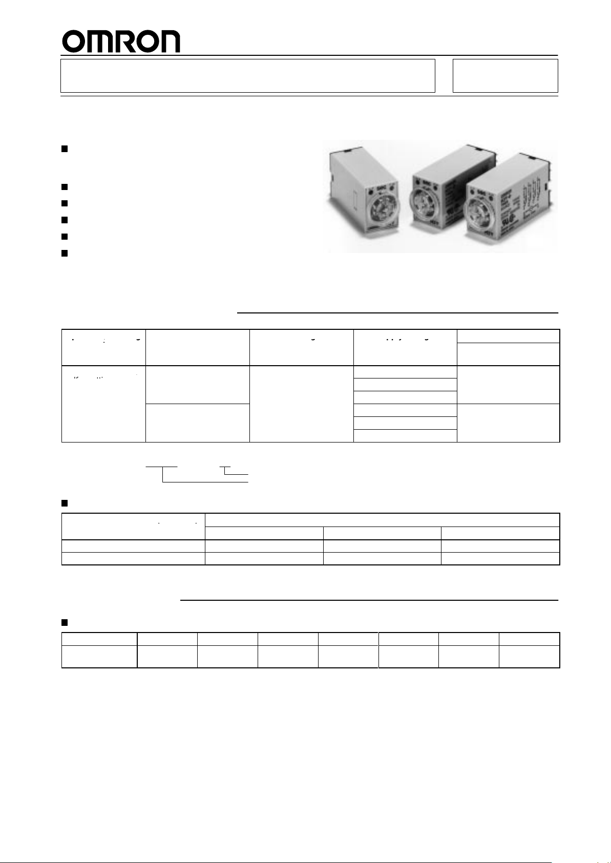
Miniature Timer Compatible with the MY
Relay
Large
transparent time-setting knob facilitates time
setting. Flat-blade and Phillips screwdrivers can
also be used for time setting.
Approved by UL and CSA.
Pin
configuration compatible with
LED indication for power and output statuses.
Conforms to EMC standards.
High repeat accuracy.
Ordering Information
MY Power Relay
.
RC
Operation/resetting
system
T
ime-limit operation/
self-resetting
Note:
Specify the model number
Ex. H3Y-2 1
Time-limit
DPDT
4PDT
10 V
AC 1 s
Accessories
Track
mounted socket (see note )
PYF08A, PYF08A-N, PYF08A-E
PYF14A, PYF14A-N, PYF14A-E
Note: T
rack mounted socket can be used as a front connecting socket.
Specifications
Time Ranges
Rated
time
T
ime setting
range
1 s 5 s
0.1 to 1 s 0.2 to 5 s
contact
, supply voltage, and rated time when ordering.
Solder terminal
PY08 PY08QN(2) PY08-02
PY14 PY14QN(2) PY14-02
T
ime ranges
0.1 s to 30 min
Rated time
Supply voltage
Back connecting socket
10 s 30 s 60 s
0.5 to 10 s 1.0 to 30 s 2.0 to 60 s
Supply voltage
1
10 V
AC
220 V
AC
24 VDC
1
10 V
AC
220 V
AC
24 VDC
W
ire-wrap terminal PC terminal
Model
Surface /DIN-track
mounting (with socket)
H3Y-2
H3Y-4
3 min 30 min
0.1 to 3 min 1.0 to 30 min
1
Page 2
H3Y
Ratings
Item H3Y-2/H3Y-4
Rated
supply voltage
Operating voltage range
Power consumption
Control outputs H3Y
Note:
With DC ratings, single-phase full-wave rectified power sources may be used.
1
10, 220 V
85% to 1
100 V
200 V
24 VDC: Relay ON:
H3Y
AC (50/60 Hz), 24 VDC (see note)
10% of rated supply voltage
AC: Relay ON:
Relay OFF:
AC: Relay ON:
Relay OFF:
Relay OFF:
-2: 5 A at 250 V
-4: 3 A at 250 V
1.5 V
A (1.3 W)
0.8 V
A (0.5 W)
1.8 V
A (1.5 W)
1.2 V
A (0.9 W)
0.9 W
0.07 W
AC, resistive load (cosφ
AC, resistive load (cosφ
= 1)
= 1)
Characteristics
Accuracy
Setting error ±
Reset time
Influence of voltage
Influence of temperature
Insulation resistance
Dielectric strength
V
ibration resistance
Shock resistance
Ambient temperature
Ambient humidity
Life expectancy
EMC Emission Enclosure: EN55011 Group 1 class A
Approved standards
Weight
Note: T
of operating time
erminal screw sections are excluded.
±
2% max.
10% (max. time division at rated voltage and room temperature)
0.1 s max.
±
2% max.
±
5% max.
100 MΩ min. (at 500 VDC)
2,000 V
non-current-carrying metal parts) (see note)
2,000 V
2,000 V
1,500 V
1,000 V
Destruction:
Malfunction:
Destruction:
Malfunction:
Operating: –10°C to 50°C (with no icing)
Operating: 35% to 85%
Mechanical:
Electrical:
H3Y
H3Y
Emission AC Mains:
Immunity ESD:
Immunity RF-interference:
Immunity Conducted Disturbance:
Immunity Burst:
UL (File No. E41515), CSA (File No. LR22310)
Conforms to EN50081-2, EN50082-2
Approx. 50 g
AC, 50/60 Hz for 1 min (between current-carrying terminals and exposed
AC, 50/60 Hz for 1 min (between operating power circuit and control output) (see note)
AC, 50/60 Hz for 1 min (between different pole contacts; 2-pole model) (see note)
AC, 50/60 Hz for 1 min (between dif
AC, 50/60 Hz for 1 min (between non-continuous contacts)
10 to 55 Hz with 1.0-mm double amplitude
10 to 55 Hz with 1.0-mm double amplitude
1,000 m/s2 (approx. 100G)
100 m/s2 (approx. 10G)
10,000,000 operations min. (under no load at 1,800 operations/h)
-2: 500,000 operations min. (5 A at 250 V
-4: 200,000 operations min. (3 A at 250 V
ferent pole contacts; 4-pole model)
AC, resistive load at 1800 operations/h)
AC, resistive load at 1800 operations/h)
EN55011 Group 1 class A
IEC801-2:
ENV50140:
ENV50141:
IEC801-4:
4 kV contact discharge (level 2)
4 kV air discharge (level 2)
10 V/m (80 MHz to 1 GHz) (level 3)
10 V (0.15 to 80 MHz) (level 3)
2 kV power-line (level 3)
2 kV I/O signal-line (level 4)
H3Y
2
Page 3
H3Y
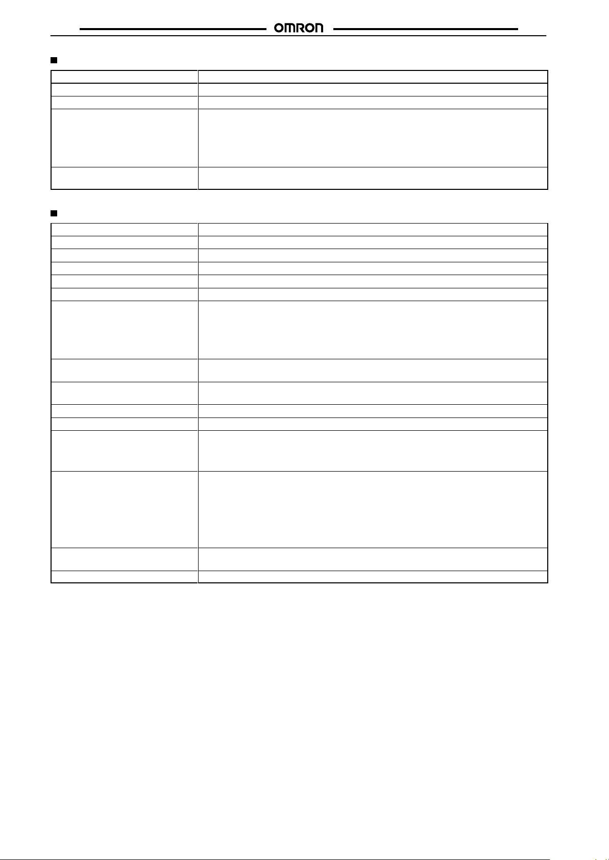
Engineering Data
H3Y
H3Y-2
3
250 VAC, cosφ
24 VDC, cosφ
Switching operations (x 10 )
Load current (A)
H3Y-4
3
250 VAC, cosφ
24 VDC, cosφ
Switching operations (x 10 )
= 1
= 1
= 1
= 1
H3Y-2
3
250 VAC, cosφ
24 VDC, L/R = 7 ms
Switching operations (x 10 )
Load current (A)
H3Y-4
3
250 VAC, cosφ
24 VDC, L/R = 7 ms
Switching operations (x 10 )
= 0.4
= 0.4
Reference: A
Reference:
maximum current of 0.6 A can be
switched at 125 VDC (cosφ
= 1).
Maximum current of 0.2 A can be
switched if L/R is 7 ms. In both
cases, a life of 100,000 operations
can be expected.
The minimum applicable load is
1 mA at 5 VDC (P reference value).
A maximum current of 0.5 A can be
switched at 125 VDC (cosφ
= 1).
Maximum current of 0.2 A can be
switched if L/R is 7 ms. In both
cases, a life of 100,000 operations
can be expected.
The minimum applicable load is
1 mA at 1 VDC (P reference value).
Load current (A)
Load current (A)
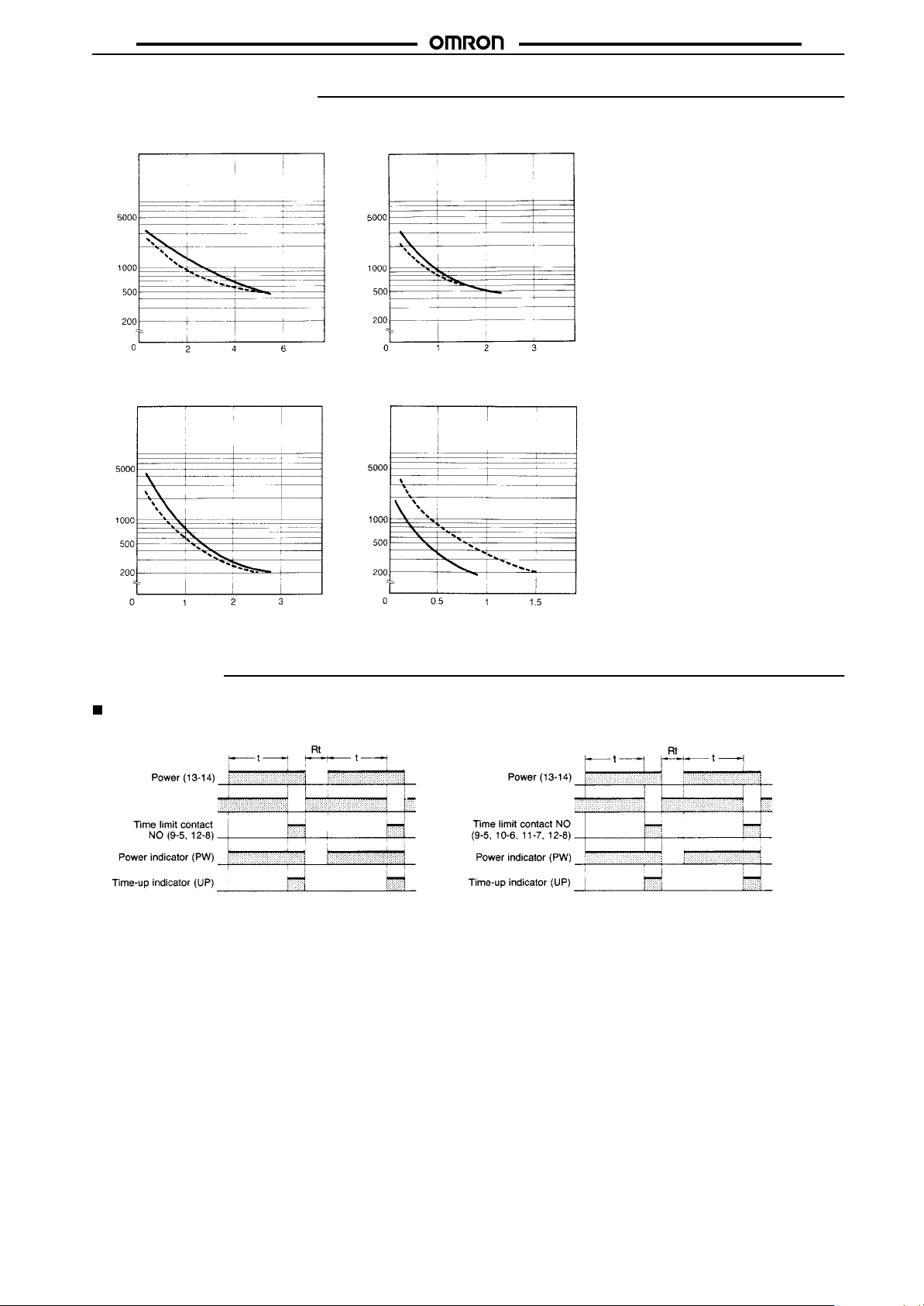
Operation
Timing Chart
H3Y-2 H3Y-4
Time limit contact
NC (9-1, 12-4)
Time limit contact NC
(9-1, 10-2, 1
1-3, 12-4)
3
Page 4

H3Y
Dimensions
Note: All
Timers
H3Y-2 H3Y-4
units are in millimeters unless otherwise indicated.
H3Y
21.5
max.
(63.0)
6.4
Accessories (Order Separately)
Use
the PYF
Track Mounting/Front Connecting Sockets
PYF08A
Two, 4.2 ×
mounting holes
PYF14A
Two, 4.2 ×
mounting holes
72
5
max.
5
jA, PYj
6
23 max.
, PYj-02, or PYjQN(2) to mount the H3Y. When ordering any one of these sockets, replace “j” with “08” or “14.”
16.5
M3
30 max.
×
3.4
35.4
6
3.4
Eight,
8 sems
6
M3
×
Fourteen,
8 sems
28
max.
6.3
T
erminal Arrangement
(T
op V
iew)
4
Terminal
(T
op V
iew)
Arrangement
(63.0)
Mounting
Two, 4.5 dia.
M4 or M3
15±0.2
Mounting Holes
Holes
59±0.3
Two, 4.5 dia.
M4 or M3
6.4
90.5
21.5
max.
6.3
H3Y
Series
PYFjA
28 max.
86.6
72 max.
29.5 max.
16.5
30 max.
35.4
6
59±0.3
4
22±0.2
4
Page 5

H3Y
H3Y
PYF08A-N
PYF14A-N
4
42332222112
8447
411231
A214A2
22 max.
4
42
8
44
PYF-08A-N
41
12
A2
14
14
34
PYF-14A-N
11
14
29.5
max.
6245
211011
1
12
5
14
11
9
A113A2
14
9
A1
13
66.5 max.
66.5 max.
30 max.
30 max.
Terminal
Terminal
Arrangement
424412
4 1
14
8 5
12 9
41 11
13
14 14
A2 A2 A1
Arrangement
42 32 22 12
4 3 2 1
44 34 24 14
8 7 6 5
12 11 10 9
41 31 21 11
14 14
A2 A2 A1
13
Mounting Holes
(for Surface Mounting)
3.2 dia.
19.8
3.6 dia.
Mounting Holes
(for Surface Mounting)
Two, 3.5 dia.
20.8
PYF08A-E
Two, 4.2 ×
mounting holes
72 max.
PYF14A-E
Two, 4.2 ×
mounting holes
72 max.
5
5
23 max.
29.5 max.
Eight,
M3
8 sems
Eight, M3 ×
8 sems
×
31
max.
31
max.
(Top View)
(Top View)
Two, 4.5 dia.
M4 or M3
Two, 4.5 dia.
M4 or M3
5
Page 6

H3Y
Back Connecting Sockets
PY08, PY14
Eight, 3× 1.2 dia. holes
only for PY08 (Fourteen, 3
× 1.2 dia. holes)
24 max.
0.3
25.5
max.
29.5
max.
Terminal
Arrangement
(Bottom View)
Panel Cutout
21.4
+0.2
25.8
0
H3Y
+0.2
0
H3Y
Series
59.3
2.7 7.7
20 max.
2.6
PY08QN, PY14QN
PY08QN(2), PY14QN(2)
24 max.
2.7
25 max. *
(See
note)
**
41.5 max.
(see note)
22 max.
29.5 max.
1
x 1
Note: With PYjQN(2), dimension * should
20 max. and dimension ** 36.5 max.
read
PY08-02, PY14-02
22
max.
2.7
0.3
4.3
16.5 max.
25.5
max.
29.5
max.
2
PY08 PY14
erminal Arrangement
T
(Bottom View)
PY08QN
PY08QN(2)
Terminal
PY14QN
PY14QN(2)
Arrangement
(Bottom View)
PY08-02 PY14-02
PYj, PYj-02,
PYjQN(2)
6
Page 7

H3Y
Socket Mounting Plates (t = 1.6)
Applicable
PY08, PY14, PY08QN(2), PY14QN(2)
Note:
PYP-18 may be cut to any desired length.
socket
For mounting 1 socket
PYP-1 PYP-18
For mounting 18 sockets
H3Y
PYP-1
Two, 3.4-dia. holes
PYP-18
Relay Hold-down Clips Y92H-3 for
PYFjA Socket
Y92H-4 for
PYj Socket
Mounting Track
PFP-100N/PFP-50N
1000 (500) (See note 2)
Note: 1. Meets
2.
DIN EN50022
This dimension applies to PFP-50N.
Spacer
PFP-S
(see note 1)
End Plate
PFP-M
7
Page 8

H3Y
Installation
Connection
H3Y-2 H3Y-4
Connect
the DC power supply to
terminals 13 and 14 according
to the polarity marks.
Precautions
When selecting a control output, use the H3Y-2 for switching ON
and OFF the power and the H3Y-4 for switching ON and OFF the
minute
load.
The
operating voltage will increase when using the H3Y in any place
where
the ambient temperature
110%
of the rated voltages (at 12 VDC: 95% to 1
at 50°C or higher
ing
Do
not leave the H3Y in time-up condition for
(for
example, more than one month in any place where the
temperature is high), otherwise the internal parts (aluminum electrolytic
capacitor) may become damaged. Therefore, the use of the
H3Y
with a relay as shown in the following circuit diagram is recom
to extend the service life of the H3Y
mended
Do
not connect the H3Y as shown in the following circuit diagram on
the
right hand side, otherwise the H3Y’s internal contacts dif
from
each other in polarity may become short-circuited.
Correct Incorrect
.
is more than 50°C. Supply 90% to
10%) when operat
a long period of time
.
H3Y
MY Relay
ambient
ferent
-
-
H3Y
Connect the DC power supply to
terminals 13 and 14 according to
the polarity marks.
Use
the following safety circuit when building a self-holding or selfresetting circuit with the H3Y and an auxiliary relay
Relay,
in combination.
: H3Y
Do
not use the
gas, or direct sunlight.
sive
Do not mount more than one H3Y closely together, otherwise the
internal parts may become damaged. Make sure that there is a
space
to
allow heat radiation.
The
internal parts may become damaged if a supply voltage other
than
the rated ones is imposed on the H3Y
applied
H3Y in places where there is excessive dust, corro
of 5 mm or
to 12 or 24 VDC, the internal element (varistor) may break.
more between any H3Y Models next to each other
. When more than 100 V is
, such as an MY
Auxiliary relay:
MY Relay
-
Limited issue for Southeast Asian countries
ALL DIMENSIONS SHOWN ARE IN MILLIMETERS.
To
convert millimeters into inches, multiply by 0.03937. T
o convert grams into ounces, multiply by 0.03527.
Cat. No. L097-E1-1 In the interest of product improvement, specifications are subject to change without notice.
OMRON Corporation
Supervisory Control Devices Division
28th Fl., Crystal T
1-2-27, Shiromi, Chuo-ku,
Osaka 540-6028 Japan
Phone: (81)6-949-6035 Fax: (81)6-949-6069
8
ower Bldg.,
Printed
in Japan
0597-2M (0597)
a
 Loading...