

Page 1
Solid-state Timer H3FA 1
Solid-state Timer
H3FA
DIP Model Timer for PC Board Use Provides
Contact and Solid-state Output
• Four time ranges are selectable.
Models suffixed -@A@: 1 s, 10 s, 1 min, 10 min.
Models suffixed -@B@: 6 s, 60 s, 6 min, 60 min.
• Timer operation may also be controlled through an external
variable resistor.
• Timer can be cleaned while mounted on a PC Board with the
sealing tape affixed.
• Twenty-four-pin IC socket can be used for mounting the Timer.
• Mountable on a 1-inch pitch rack.
(H 19.5 × W 36.9 × D 17.75 mm)
Model Number Structure
Note: This model number legend includes combinations that are not available. Before ordering, please check the “List of Models” on page 2 for
availability.
1. Time-limit contact
None: Contact outputs (SPST-NO + SPST-NC)
S: Solid-state outputs
2. Time range
A: 1 s to 10 min
B: 6 s to 60 min
3. Operation/resetting system
None: Time-limit operation/power-OFF resetting and external
resetting, Integrating operation/power-OFF resetting and
external resetting
U: Instantaneous operation, time-limit resetting/external
resetting
4. Supply voltage
For contact output models
5DC: 5 V DC
6DC: 6 V DC
12DC: 12 V DC
24DC: 24 V DC
For solid-state output models
5/6DC: 5/6 V DC
12/24DC: 12/24 V DC
123 4
H3FA- @ @ @ @
Please read and understand this catalog before purchasing the products. Please consult OMRON representative if you have any questions or
comments. Refer to “Warranty and Application Considerations” on page 12 and “Safety Precautions” on page 9.
Page 2
2 Solid-state Timer H3FA
Ordering Information
■ List of Models
Note: The desired operation/resetting system is selected by short-circuiting and opening the specified terminals.
Specifications
■ Time Ranges
Note: 1. The above timing ranges apply when the internal variable resistor of H3FA is used.
2. The external variable resistor may also be used by opening the terminal connected to the internal variable resistor.
3. Wire the appropriate terminal to select a time setting range. Refer to “Rated Time and Terminal Connections” on page 4 for details.
Item Model H3FA-A H3FA-B H3FA-SA H3FA-SB H3FA-AU H3FA-BU H3FA-SAU H3FA-SBU
Operation/resetting
system (See note.)
Time-limit operation/power-OFF resetting and external
resetting,
Integration operation/power-OFF resetting and external
resetting
Instantaneous operation, time-limit resetting/external
resetting
Time-limit contact Contact output
(SPST-NO + SPST-NC)
Solid-state output Contact output
(SPST-NO + SPST-NC)
Solid-state output
Instantaneous
contact
---
Mounting method Surface mounting (with IC socket or direct mounting on PC Board)
Time range 1 s to 10 min 6 s to 60 min 1 s to 10 min 6 s to 60 min 1 s to 10 min 6 s to 60 min 1 s to 10 min 6 s to 60 min
Supply
voltage
5 V DC H3FA-A 5DC H3FA-B 5DC --- --- H3FA-AU
5DC
H3FA-BU
5DC
--- ---
6 V DC H3FA-A 6DC H3FA-B 6DC --- --- H3FA-AU
6DC
--- --- ---
12 V DC H3FA-A
12DC
H3FA-B
12DC
--- --- H3FA-AU
12DC
H3FA-BU
12DC
--- ---
24 V DC H3FA-A
24DC
H3FA-B
24DC
--- --- H3FA-AU
24DC
H3FA-BU
24DC
--- ---
5/6 V DC --- --- H3FA-SA
5/6DC
H3FA-SB
5/6DC
--- --- H3FA-SAU
5/6DC
H3FA-SBU
5/6DC
12/24 V DC --- --- H3FA-SA
12/24DC
H3FA-SB
12/24DC
--- --- H3FA-SAU
12/24DC
H3FA-SBU
12/24DC
Model Rated time Time setting range
H3FA-A 1 s 0.1 to 1 s
H3FA-AU 10 s 1 to 10 s
H3FA-SA 1 min 0.1 to 1 min
H3FA-SAU 10 min 1 to 10 min
H3FA-B 6 s 0.6 to 6 s
H3FA-BU 60 s 6 to 60 s
H3FA-SB 6 min 0.6 to 6 min
H3FA-SBU 60 min 6 to 60 min
Page 3
Solid-state Timer H3FA 3
■ Ratings
Note: 1. Permissible ripple: 20% max. (3% max. at 5, 6 V DC-operated models)
2. Supply voltage can be selected by short-circuiting (12 V DC) or opening (24 V DC) the specified terminals.
■ Characteristics
Note: 1. Add or subtract 10 ms to the ratings when using a timer with a rated time of 1 s.
2. Applicable to contact output models.
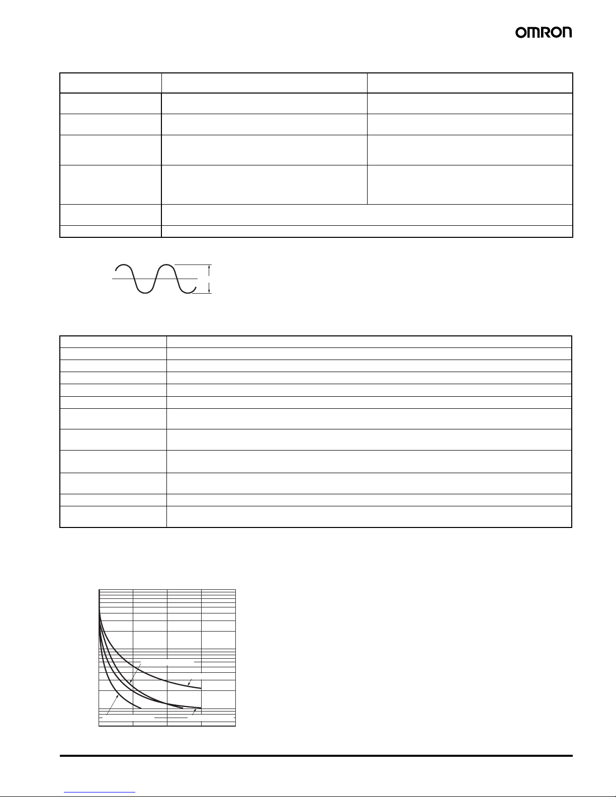
■ Life-test Curve (Reference Values)
Item H3FA-A/ H3FA-B
H3FA-AU/ H3FA-BU
H3FA-SA/ H3FA-SB
H3FA-SAU/ H3FA-SBU
Rated supply voltage 5 V DC, 6V DC, 12V DC, 24 V DC (See note 1.) 5/6 V DC (See note 1.)
12/24 V DC (See notes 1 and 2.)
Operating voltage range 5 V DC: 90% to 110% of rated supply voltage
6, 12, 24 V DC: 85% to 110% of rated supply voltage
5/6 V DC: 90% to 110% of rated supply voltage
12/24 V DC: 85% to 110% of rated supply voltage
Power consumption 5, 6 V DC: approx. 230 mW
12 V DC: approx. 270 mW
24 V DC: approx. 330 mW
5/6 V DC: approx. 80 mW
12 V DC: approx. 100 mW
24 V DC: approx. 240 mW
Control outputs Contact output: SPST-NO + SPST-NC,
3 A at 250 V AC with resistive load,
Minimum applied load: 10 mA at 5 V DC
(Failure level: P, reference value)
Solid-state output: 150 mA max. at 30 V DC
Residual voltage: 1.0 V max.
Ambient temperature Operating:
−10°C to 55°C (with no icing)
Storage:
−25°C to 65°C (with no icing)
Ambient humidity 35% to 85%
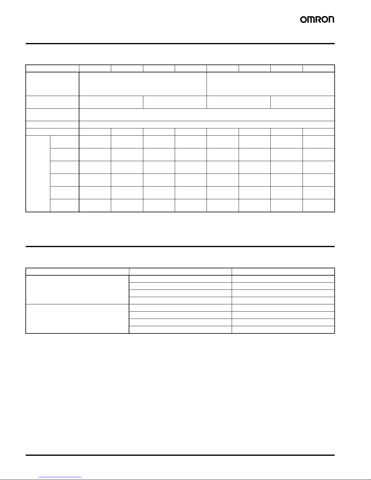
X
Mean X/Mean value × 100 ≤ 20 (%) max.
Where,
Accuracy of operating time ±0.5% FS max. (See note 1.)
Setting error 0 to 30 % FS max. (at 20°C , at rated voltage)
Reset time 10 ms max.
Influence of voltage ±1% FS max. (2% FS max. for 5, 6, 5/6 V DC-operated models)
Influence of temperature ±5% FS max. (See note 1.)
Insulation resistance 100 M
Ω min. (at 500 V DC)
Dielectric strength 1,500 V AC, 50/60 Hz for 1 min (between control output and operating circuit) (See note 2.)
1,000 V AC, 50/60 Hz for 1 min (between contacts not located next to each other) (See note 2.)
Vibration resistance Destruction: 10 to 55 Hz with 0.375-mm single amplitude in 3 directions for 1 hour each
Malfunction: 10 to 55 Hz with 0.25-mm single amplitude in 3 directions for 10 minutes each
Shock resistance
Destruction: 1,000 m/s
2
3 times each in 6 directions
Malfunction: 100 m/s
2
3 times each in 6 directions
Life expectancy Mechanical: 10,000,000 operations min. (under no load at 1,800 operations/h)
Electrical: 100,000 operations min. (3 A at 250 V AC, resistive load at 1,800 operations/h)
Approved safety standards UL508, CSA C22.2 No.14
Weight Contact output models: approx. 15 g
Solid-state output models: approx. 10 g
1,000
700
500
300
100
70
50
30
10
5
01234
Load current
(A)
7
24 VDC L/R=7 ms
24 VDC cosφ=1
250 VAC cosφ=1250 VAC cosφ=0.4
Switching operations (x10
4
)
Page 4

4 Solid-state Timer H3FA
Connections
■ Block Diagrams
Note: All diagrams are views from the top.
H3FA-A, H3FA-B, H3FA-SA, H3FA-SB
When the input voltage is applied, the CR oscillator circuit in the
Timer starts to oscillate via the power supply circuit, the counter
circuit counts up to the preset setting, and an output signal is
produced. A transistor amplifies this signal to drive the load.
The voltage across the H3FA-SA and -SB (solid-state output loads)
is the load input voltage minus the residual voltage when the
transistor turns ON.
H3FA-AU, H3FA-BU, H3FA-SAU, H3FA-SBU
■ Rated Time and Terminal Connections
Note: 1. Short-circuit terminals 21 and 22 when using the internal variable resistor of H3FA.
2. An external resistor can also be used by opening terminals 21 and 22. When using an external resistor (1 M
Ω for H3FA-A/-SA, 3 MΩ for H3FA-B/
-SB), connect it between terminals 21 and 23.
Model Terminal connection
H3FA-A/-SA/-AU/-SAU 1 s 10 s 1 min 10 min
H3FA-B/-SB/-BU/-SBU 6 s 60 s 6 min 60 min
Power
supply
For the external resistor
For the internal variable
resistor
Power supply
circuit
Voltage stabili-
zer circuit
CR oscillator
circuit
Counter circuit
Output amplifier
circuit
Reset circuit
Reset input
Time range
selector
Contact output (NO contact for
time-limit operation)
Contact output (NC contact for
time-limit operation)
Power
supply
For the external resistor
For the internal variable
resistor
Power supply
circuit
Voltage stabili-
zer circuit
CR oscillator
circuit
Counter circuit
Output amplifier
circuit
Reset circuit
Reset input
5 to 24 V DC
Time range selector
Load
Short for 12 V DC
Open for 24 V DC (See note.)
Contact Output Solid-state Output
10: Solid-state output terminal
12: Terminal for the internal load surge absorbing diode
Note: When using 12/24 V DC
-operated models.
Power
supply
For the external resistor
For the internal variable resistor
Power supply
circuit
Voltage stabili-
zer circuit
CR oscillator
circuit
Counter circuit
Output amplifier
circuit
Reset circuit
Start circuit
Power
supply
For the external resistor
For the internal variable resistor
Power supply
circuit
Voltage stabili-
zer circuit
CR oscillator
circuit
Counter circuit
Output amplifier
circuit
Reset circuit
Start circuit
5 to 24 V DC
Load
150 mA max.
Load surgeabsorbing diode
Short for 12 V DC
Open for 24 V DC (See note.)
Solid-state OutputContact Output
Note: When using a 12/24 V DC-operated model.
231 231 231
231
Page 5

Solid-state Timer H3FA 5
Operation
■ Timing Charts and External Connections
Note: Do not apply voltage to any terminals other than the power supply terminals. Otherwise, the internal circuits may be damaged.
H3FA-A, H3FA-B, H3FA-SA, H3FA-SB
Standard Operation (ON-delay operation)
When the power is turned ON and the set time has elapsed, an
output is produced. (Power turns ON when power terminals 1 and 24
are shorted or when terminals 13 and 15 are shorted when using a
12/24 V DC-operated model with a 12 V DC power supply.)
When connecting an external resistor to the Timer, connect it
between terminals 21 and 23, and open terminals 21 and 22. Refer
to “External Resistors and Operating Time (Reference Value)” on
page 7. When operating with an external reset input, short terminals
1 and 4. The Timer will start operating even if reset terminals 1 and 4
are open when the power is turned ON.
In this case, the current flow is approximately 0.1 mA. If a contact is
used for control, use a contact with high contact reliability, If a
transistor is used for control, use an I
CEO
of 10 µA and a VCE (sat) of
0.5 V or less.
Note: When using a 12/24 V DC-operated model with a 12 V DC
power supply, short terminals 13 and 15.
Contact Output (Top View)
Solid-state Output (Top View)
When using the 12/24 V DC-operated model with a 24 V DC power
supply, open terminals 13 and 15.
Integration Operation
By opening the terminals connected to the internal variable resistor,
Timer operation can be interrupted to enable the Timer to perform
time integration operations. Interrupt Timer operation by opening
terminals 21 and 22 when using the internal variable resistor or
terminals 21 and 23 when using the external resistor. Timer
operation can be resumed by reconnecting the terminals.
Note: 1. Control output is provided when the set time has elapsed
(T
1
+ T2 or T3 + T4).
2. When using a 12/24 V DC-operated model with a 12 V DC
power supply, short terminals 13 and 15.
Contact Output (Top View)
Solid-state Output (Top View)
When using the 12/24 V DC-operated model with a 24 V DC power
supply, open terminals 13 and 15.
Set time Set time Set timeSet time
10 ms
min.
Power supply
(terminals 1 and 24)
(See note.)
Reset input
(terminals 1 and 4)
SPST-NO contact output
(terminals 13 and 16)
Solid-state output
(terminals 1 and 10)
OFFON
OFFON
Short Short
Open
SPST-NC contact output
(
terminals 9 and 12
)
10 ms
min.
ShortShort Open Open Short
ON OFF ON
Power supply (terminals 1 and 24)
(See note.)
For internal variable resistor
(terminals 21 and 22)
SPST-NO contact output
(terminals 13 and 16)
Reset input
(terminals 1 and 4)
SPST-NC contact output
(terminals 9 and 12)
T1 T2 T3 T4 Tn
For external resistor
(terminals 21 and 23)
Solid-state output
(terminals 1 and 10)
Page 6

6 Solid-state Timer H3FA
H3FA-AU, H3FA-BU, H3FA-SAU, H3FA-SBU
One-shot Output Operation
Turn ON the power and apply a start input (short terminals 6 and 1).
(Power turns ON when power terminals 1 and 24 are shorted or
when terminals 13 and 15 are shorted when using a 12/24 V DCoperated model with a 12 V DC power supply.) An output is produced
immediately and is reset when the set time has elapsed.
If the reset input is applied (short terminals 4 and 1) with no start
input (open terminals 6 and 1) while the Timer is operating, the Timer
stops operating and the output is reset.
When operating with an external start or reset input, the current flow
from terminal 6 to terminal 1 (start input) or from terminal 4 to
terminal 1 (reset input) is approximately 0.1 mA. A highly reliable
contact is therefore recommended for the start and reset inputs.
Use an I
CEO
of 10 µA and a VCE (sat) of 0.5 V or less for transistor
control. When connecting an external resistor to the Timer, connect it
between terminals 21 and 23, and open terminals 21 and 22.
Note: 1. When using a 12/24 V DC-operated model with a 12 V DC
power supply, short terminals 13 and 15.
2. The start input is disabled during the time limit.
3. T denotes the set time. t
1
< T
Contact Output (Top view)
Solid-state Output (Top View)
When using the 12/24 V DC-operated model with a 24 V DC power
supply, open terminals 13 and 15.
OFF-delay Operation
Turn ON the power and apply a start input (short terminals 6 and 1).
(Power turns ON when power terminals 1 and 24 are shorted or
when terminals 13 and 15 are shorted when using a 12/24 V DCoperated model with a 12 V DC power supply.) An output is produced
immediately. If the start input is applied constantly, however, the reset
input can be applied until the set time elapses to stop time-limit
operation. (An output is produced when the start input is applied
even when the constant reset input is ON prior to the start input.)
The time-limit operation starts when the reset input terminals are
opened, and the output is reset when the set time has elapsed.
When operating with an external start or reset input, the current flow
is approximately 0.1 mA. A highly reliable contact is therefore
recommended for the start and reset inputs. Use an I
CEO
of 10 µA
and a V
CE
(sat) of 0.5 V or less for transistor control.
Note: 1. When using a 12/24 V DC-operated model with a 12 V DC
power supply, short terminals 13 and 15.
2. T denotes the set time. t
1
, t2, and t3 < T
Contact Output (Top view)
Solid-state Output (Top View)
When using the 12/24 V DC-operated model with a 24 V DC power
supply, open terminals 13 and 15.
ON
Short
Open
TTT
t1
10ms
min.
(See
note 2.)
10ms
min.
Power supply
(terminals 1 and 24)
(See note 1.)
Start input
(terminals 1 and 6)
Reset input
(terminals 1 and 4)
SPST-NO contact output
(terminals 13 and 16)
SPST-NC contact output
(terminals 9 and 12)
Solid-state output
(terminals 1 and 10)
Contact output
(SPST-NC contact for
time-limit operation)
Power supply
(terminals 1 and 24)
(See note 1.)
Start input
(terminals 1 and 6)
Reset input
(terminals 1 and 4)
SPST-NO contact output
(terminals 13 and 16)
Solid-state output
(terminals 1 and 10)
SPST-NC contact output
(terminals 9 and 12)
ON
Short Open
TTT
t1
t2
t3
Page 7

Solid-state Timer H3FA 7
■ External Resistors and Operating Time (Reference Value)
Refer to the following characteristics diagrams
when using an external resistor.
• Use an external resistor rated at about
0.1 W/1 M
Ω for H3FA-A, -SA, -AU, and -SAU
or 0.1 W/3 M
Ω for H3FA-B, -SB, -BU, and -
SBU.
• Do not run leads parallel to power lines and
keep the leads shorter than 2 m to minimize
the effects of external noise.
• The characteristics diagrams represent
typical data. The factory set operating time
may not always be uniform from one product
to another. A variable resistor is
recommended if more precise time
adjustments are required. The operating time
is slightly longer than the set time as the
length of the lead increases.
■ Extending the Reset Time
DIP Timers have a shorter reset time than that of conventional timers
for use in solid-state circuit applications. To extend the reset time to
that of conventional timers, i.e., about 100 ms, during operation,
connect the Timer to a capacitor from the table as shown in the
following diagram. The reset time after the set time has elapsed will
vary with the load relay, so select an appropriate capacitor for the
load relay.
External resistor (MΩ
)
120
100
80
60
40
20
0 0.5 1 1.5
Operating time (%)
H3FA-B/-SB/-BU/-SBUH3FA-A/-SA/-AU/-SAU
External resistor (MΩ)
120
100
80
60
40
20
01234
Operating time (%)
Rated voltage Capacitor capacity
12 V DC 10
µF, 25 V
24 V DC 4.7
µF, 50 V
5 and 6 V DC 22
µF, 16 V
C
24 23 22 21
1234
Page 8

8 Solid-state Timer H3FA
Dimensions
Note: All units are in millimeters unless otherwise indicated.
H3FA-A, H3FA-B, H3FA-SA, H3FA-SB
H3FA-AU, H3FA-BU, H3FA-SAU, H3FA-SBU
Mounting holes (Top view)
Applicable Connecting Socket
Standard 24-pin IC socket can be used to mount
the Timer.
(OMRON equivalent: XR2A-2401-N)
H3FA-A/-B
H3FA-SA/-SB
Twelve, 1.0 dia. holes
Twelve, 1.0 dia. holes
Mounting holes (Top View)
Applicable Connecting Socket
Standard 24-pin IC socket can be used for
mounting the Timer.
(OMRON equivalent: XR2A-2401-N)
H3FA-AU/-BU
H3FA-SAU/-SBU
Page 9

Solid-state Timer H3FA 9
Safety Precautions
■ Precautions for Safe Use
Observe the following items to ensure the safe use of this product.
Environmental Precautions
• Store the H3FA within the specified ratings. If the H3FA has been
stored at a temperature of –10°C or lower, let it stand for 3 hours or
longer at room temperature before turning ON the power supply.
• Use the H3FA within the specified ratings for operating temperature
and humidity.
• Do not operate the H3FA in locations subject to sudden or extreme
changes in temperature, or locations where high humidity may
result in condensation.
• Do not use the H3FA in locations subject to vibrations or shock.
Extended use in such locations may result in damage due to stress.
• Do not use the H3FA in locations subject to excessive dust,
corrosive gas, or direct sunlight.
Usage Precautions
• Install a switch or circuit breaker that allows the operator to
immediately turn OFF the power, and label it to clearly indicate its
function.
• Be sure to wire the terminals correctly.
• Internal elements may be destroyed if a voltage outside the rated
voltage is applied.
• Maintain voltage fluctuations in the power supply within the
specified range.
■ Precautions for Correct Use
• Do not use excessive force to turn the time setting knob. Otherwise,
it may be damaged.
• When more precise operating time settings are required, measure
the operating time prior to use and adjust the time setting knob
accordingly.
• Be very careful when handling terminal leads.
• Do not touch terminals with hands or objects that may be statically
charged from mounting, transport, or other activities. Otherwise,
the terminals may be damaged. Discharge static prior to handling
the Timers by touching a grounded object or by using another
method.
• Refer to the following diagram for the set values for various
operating times.
• When cleaning the timer, confirm that the sealing tape is securely
in place. Do not clean without this sealing tape affixed.
Use alcohol type (IPA, ethanol) solvent, which are less chemically
reactive. Note that use of other solvents may damage the materials
used for the Timer. Clean the Timer in less than 2 minutes. The
cleaning solution must be 50
°C or less.
The tails of the connecting leads are solder-plated with
consideration given to temperature at the time of soldering. When
soldering the leads, keep the temperature at 260
°C±5°C and
complete soldering within 10 s. Do not use ultrasonic cleaning.
130
120
100
80
60
40
20
0 102030405060708090100
Set value
(%)
Operating time (%)
Operating
range
Page 10

10 Solid-state Timer H3FA
Page 11

Solid-state Timer H3FA 11
Page 12

12
In the interest of product improvement, specifications are subject to change without notice.
ALL DIMENSIONS SHOWN ARE IN MILLIMETERS.
To convert millimeters into inches, multiply by 0.03937. To convert grams into ounces, multiply by 0.03527.
Cat. No. L038-E1-07
OMRON Corporation
Industrial Automation Company
Industrial Devices and Components Division H.Q.
Industrial Control Components Department
Shiokoji Horikawa, Shimogyo-ku,
Kyoto, 600-8530 Japan
Te l :
(81)
75-344-7119/Fax: (81)75-344-7149
Printed in Japan
0105-0.5C (0696) (M)
Warranty and Application Considerations
Warranty and Limitations of Liability
WARRANTY
OMRON's exclusive warranty is that the products are free from defects in materials and workmanship for a period of one year (or
other period if specified) from date of sale by OMRON.
OMRON MAKES NO WARRANTY OR REPRESENTATION, EXPRESS OR IMPLIED, REGARDING NON-INFRINGEMENT,
MERCHANTABILITY, OR FITNESS FOR PARTICULAR PURPOSE OF THE PRODUCTS. ANY BUYER OR USER
ACKNOWLEDGES THAT THE BUYER OR USER ALONE HAS DETERMINED THAT THE PRODUCTS WILL SUITABLY MEET
THE REQUIREMENTS OF THEIR INTENDED USE. OMRON DISCLAIMS ALL OTHER WARRANTIES, EXPRESS OR
IMPLIED.
LIMITATIONS OF LIABILITY
OMRON SHALL NOT BE RESPONSIBLE FOR SPECIAL, INDIRECT, OR CONSEQUENTIAL DAMAGES, LOSS OF PROFITS,
OR COMMERCIAL LOSS IN ANY WAY CONNECTED WITH THE PRODUCTS, WHETHER SUCH CLAIM IS BASED ON
CONTRACT, WARRANTY, NEGLIGENCE, OR STRICT LIABILITY.
In no event shall the responsibility of OMRON for any act exceed the individual price of the product on which liability is asserted.
IN NO EVENT SHALL OMRON BE RESPONSIBLE FOR WARRANTY, REPAIR, OR OTHER CLAIMS REGARDING THE
PRODUCTS UNLESS OMRON'S ANALYSIS CONFIRMS THAT THE PRODUCTS WERE PROPERLY HANDLED, STORED,
INSTALLED, AND MAINTAINED AND NOT SUBJECT TO CONTAMINATION, ABUSE, MISUSE, OR INAPPROPRIATE
MODIFICATION OR REPAIR.
Application Considerations
SUITABILITY FOR USE
OMRON shall not be responsible for conformity with any standards, codes, or regulations that apply to the combination of
products in the customer's application or use of the products.
Take all necessary steps to determine the suitability of the product for the systems, machines, and equipment with which it will
be used.
Know and observe all prohibitions of use applicable to this product.
NEVER USE THE PRODUCTS FOR AN APPLICATION INVOLVING SERIOUS RISK TO LIFE OR PROPERTY WITHOUT
ENSURING THAT THE SYSTEM AS A WHOLE HAS BEEN DESIGNED TO ADDRESS THE RISKS, AND THAT THE OMRON
PRODUCTS ARE PROPERLY RATED AND INSTALLED FOR THE INTENDED USE WITHIN THE OVERALL EQUIPMENT OR
SYSTEM.
Disclaimers
CHANGE IN SPECIFICATIONS
Product specifications and accessories may be changed at any time based on improvements and other reasons. Consult with
your OMRON representative at any time to confirm actual specifications of purchased product.
DIMENSIONS AND WEIGHTS
Dimensions and weights are nominal and are not to be used for manufacturing purposes, even when tolerances are shown.
 Loading...