

Omron H3FA DATASHEET
Solid-state Timer
H3FA
Please read and understand this catalog before purchasing the products. Please consult OMRON representative if you have any questions or
comments. Refer to “Warranty and Application Considerations” on page 12 and “Safety Precautions” on page 9.
DIP Model Timer for PC Board Use Provides
Contact and Solid-state Output
• Four time ranges are selectable.
Models suffixed -@A@: 1 s, 10 s, 1 min, 10 min.
Models suffixed -@B@: 6 s, 60 s, 6 min, 60 min.
• Timer operation may also be controlled through an external
variable resistor.
• Timer can be cleaned while mounted on a PC Board with the
sealing tape affixed.
• Twenty-four-pin IC socket can be used for mounting the Timer.
• Mountable on a 1-inch pitch rack.
(H 19.5 × W 36.9 × D 17.75 mm)
Model Number Structure
Note: This model number legend includes combinations that are not available. Before ordering, please check the “List of Models” on page 2 for
availability.
H3FA- @ @ @ @
123 4
1. Time-limit contact
None: Contact outputs (SPST-NO + SPST-NC)
S: Solid-state outputs
2. Time range
A: 1 s to 10 min
B: 6 s to 60 min
3. Operation/resetting system
None: Time-limit operation/power-OFF resetting and external
resetting, Integrating operation/power-OFF resetting and
external resetting
U: Instantaneous operation, time-limit resetting/external
resetting
4. Supply voltage
For contact output models
5DC: 5 V DC
6DC: 6 V DC
12DC: 12 V DC
24DC: 24 V DC
For solid-state output models
5/6DC: 5/6 V DC
12/24DC: 12/24 V DC
Solid-state Timer H3FA 1
Ordering Information
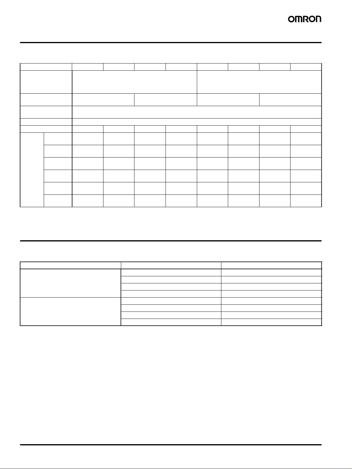
■ List of Models
Item Model H3FA-A H3FA-B H3FA-SA H3FA-SB H3FA-AU H3FA-BU H3FA-SAU H3FA-SBU
Operation/resetting
system (See note.)
Time-limit contact Contact output
Instantaneous
contact
Mounting method Surface mounting (with IC socket or direct mounting on PC Board)
Time range 1 s to 10 min 6 s to 60 min 1 s to 10 min 6 s to 60 min 1 s to 10 min 6 s to 60 min 1 s to 10 min 6 s to 60 min
Supply
voltage
Note: The desired operation/resetting system is selected by short-circuiting and opening the specified terminals.
5 V DC H3FA-A 5DC H3FA-B 5DC --- --- H3FA-AU
6 V DC H3FA-A 6DC H3FA-B 6DC --- --- H3FA-AU
12 V DC H3FA-A
24 V DC H3FA-A
5/6 V DC --- --- H3FA-SA
12/24 V DC --- --- H3FA-SA
Time-limit operation/power-OFF resetting and external
resetting,
Integration operation/power-OFF resetting and external
resetting
(SPST-NO + SPST-NC)
---
12DC
24DC
H3FA-B
12DC
H3FA-B
24DC
Solid-state output Contact output
--- --- H3FA-AU
--- --- H3FA-AU
5/6DC
12/24DC
H3FA-SB
5/6DC
H3FA-SB
12/24DC
Instantaneous operation, time-limit resetting/external
resetting
(SPST-NO + SPST-NC)
5DC
6DC
12DC
24DC
--- --- H3FA-SAU
--- --- H3FA-SAU
H3FA-BU
5DC
--- --- ---
H3FA-BU
12DC
H3FA-BU
24DC
Solid-state output
--- ---
--- ---
--- ---
5/6DC
12/24DC
H3FA-SBU
5/6DC
H3FA-SBU
12/24DC
Specifications
■ Time Ranges
Model Rated time Time setting range
H3FA-A 1 s 0.1 to 1 s
H3FA-AU 10 s 1 to 10 s
H3FA-SA 1 min 0.1 to 1 min
H3FA-SAU 10 min 1 to 10 min
H3FA-B 6 s 0.6 to 6 s
H3FA-BU 60 s 6 to 60 s
H3FA-SB 6 min 0.6 to 6 min
H3FA-SBU 60 min 6 to 60 min
Note: 1. The above timing ranges apply when the internal variable resistor of H3FA is used.
2. The external variable resistor may also be used by opening the terminal connected to the internal variable resistor.
3. Wire the appropriate terminal to select a time setting range. Refer to “Rated Time and Terminal Connections” on page 4 for details.
2 Solid-state Timer H3FA
■ Ratings
(A)
Item H3FA-A/ H3FA-B
H3FA-AU/ H3FA-BU
H3FA-SA/ H3FA-SB
H3FA-SAU/ H3FA-SBU
Rated supply voltage 5 V DC, 6V DC, 12V DC, 24 V DC (See note 1.) 5/6 V DC (See note 1.)
12/24 V DC (See notes 1 and 2.)
Operating voltage range 5 V DC: 90% to 110% of rated supply voltage
6, 12, 24 V DC: 85% to 110% of rated supply voltage
Power consumption 5, 6 V DC: approx. 230 mW
12 V DC: approx. 270 mW
24 V DC: approx. 330 mW
Control outputs Contact output: SPST-NO + SPST-NC,
3 A at 250 V AC with resistive load,
5/6 V DC: 90% to 110% of rated supply voltage
12/24 V DC: 85% to 110% of rated supply voltage
5/6 V DC: approx. 80 mW
12 V DC: approx. 100 mW
24 V DC: approx. 240 mW
Solid-state output: 150 mA max. at 30 V DC
Residual voltage: 1.0 V max.
Minimum applied load: 10 mA at 5 V DC
(Failure level: P, reference value)
Ambient temperature Operating:
Storage:
−10°C to 55°C (with no icing)
−25°C to 65°C (with no icing)
Ambient humidity 35% to 85%
Note: 1. Permissible ripple: 20% max. (3% max. at 5, 6 V DC-operated models)
Where,
Mean X/Mean value × 100 ≤ 20 (%) max.
X
2. Supply voltage can be selected by short-circuiting (12 V DC) or opening (24 V DC) the specified terminals.
■ Characteristics
Accuracy of operating time ±0.5% FS max. (See note 1.)
Setting error 0 to 30 % FS max. (at 20°C , at rated voltage)
Reset time 10 ms max.
Influence of voltage ±1% FS max. (2% FS max. for 5, 6, 5/6 V DC-operated models)
Influence of temperature ±5% FS max. (See note 1.)
Insulation resistance 100 M
Dielectric strength 1,500 V AC, 50/60 Hz for 1 min (between control output and operating circuit) (See note 2.)
Vibration resistance Destruction: 10 to 55 Hz with 0.375-mm single amplitude in 3 directions for 1 hour each
Shock resistance
Life expectancy Mechanical: 10,000,000 operations min. (under no load at 1,800 operations/h)
Approved safety standards UL508, CSA C22.2 No.14
Weight Contact output models: approx. 15 g
Note: 1. Add or subtract 10 ms to the ratings when using a timer with a rated time of 1 s.
2. Applicable to contact output models.
Ω min. (at 500 V DC)
1,000 V AC, 50/60 Hz for 1 min (between contacts not located next to each other) (See note 2.)
Malfunction: 10 to 55 Hz with 0.25-mm single amplitude in 3 directions for 10 minutes each
Destruction: 1,000 m/s
Malfunction: 100 m/s
2
3 times each in 6 directions
2
3 times each in 6 directions
Electrical: 100,000 operations min. (3 A at 250 V AC, resistive load at 1,800 operations/h)
Solid-state output models: approx. 10 g
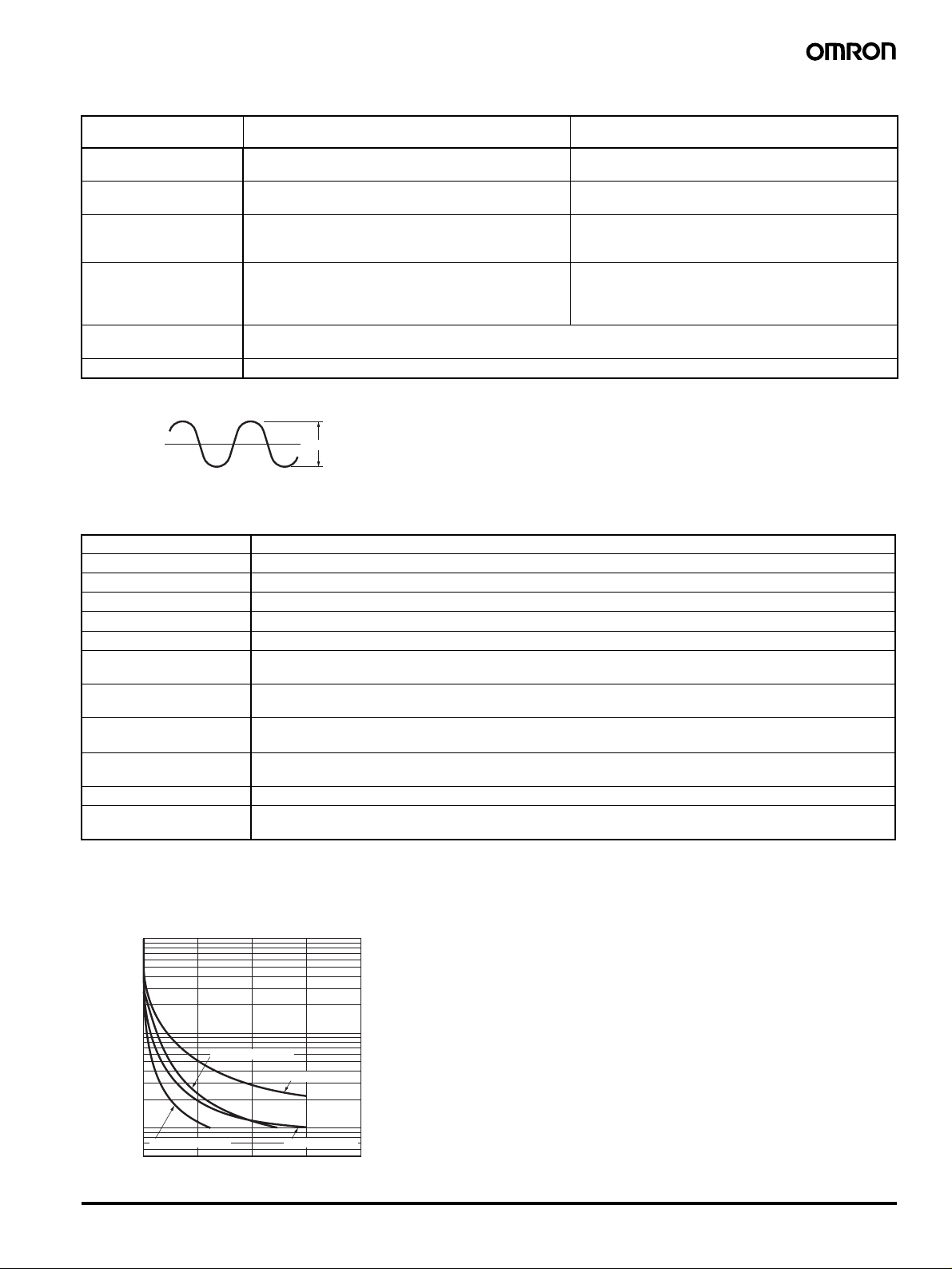
■ Life-test Curve (Reference Values)
)
4
1,000
700
500
300
100
70
Switching operations (x10
50
30
10
7
5
01234
24 VDC L/R=7 ms
24 VDC cosφ=1
250 VAC cosφ=1250 VAC cosφ=0.4
Load current
Solid-state Timer H3FA 3

Connections
■ Block Diagrams
Note: All diagrams are views from the top.
H3FA-A, H3FA-B, H3FA-SA, H3FA-SB
When the input voltage is applied, the CR oscillator circuit in the
Timer starts to oscillate via the power supply circuit, the counter
circuit counts up to the preset setting, and an output signal is
produced. A transistor amplifies this signal to drive the load.
Contact Output Solid-state Output
For the external resistor
For the internal variable
resistor
Contact output (NO contact for
time-limit operation)
The voltage across the H3FA-SA and -SB (solid-state output loads)
is the load input voltage minus the residual voltage when the
transistor turns ON.
For the external resistor
For the internal variable
resistor
Short for 12 V DC
Open for 24 V DC (See note.)
Power
supply
Power supply
circuit
Time range
selector
CR oscillator
Voltage stabili-
zer circuit
Reset input
circuit
Counter circuit
Reset circuit
Output amplifier
circuit
Contact output (NC contact for
time-limit operation)
H3FA-AU, H3FA-BU, H3FA-SAU, H3FA-SBU
For the external resistor
For the internal variable resistor
Power
supply
Power supply
circuit
CR oscillator
Voltage stabili-
zer circuit
circuit
Counter circuit
Reset circuit
Output amplifier
circuit
Start circuit
Power
supply
Solid-state OutputContact Output
Power
supply
CR oscillator
Power supply
circuit
Time range selector
10: Solid-state output terminal
12: Terminal for the internal load surge absorbing diode
Note: When using 12/24 V DC
Power supply
circuit
Voltage stabili-
circuit
Voltage stabili-
zer circuit
zer circuit
Counter circuit
Reset circuit
Reset input
5 to 24 V DC
For the external resistor
For the internal variable resistor
CR oscillator
circuit
Counter circuit
Reset circuit
Output amplifier
circuit
Output amplifier
circuit
Start circuit
-operated models.
Short for 12 V DC
Open for 24 V DC (See note.)
Load
150 mA max.
Load surgeabsorbing diode
5 to 24 V DC
Note: When using a 12/24 V DC-operated model.
■ Rated Time and Terminal Connections
Model Terminal connection
231 231 231
H3FA-A/-SA/-AU/-SAU 1 s 10 s 1 min 10 min
H3FA-B/-SB/-BU/-SBU 6 s 60 s 6 min 60 min
Note: 1. Short-circuit terminals 21 and 22 when using the internal variable resistor of H3FA.
2. An external resistor can also be used by opening terminals 21 and 22. When using an external resistor (1 M
-SB), connect it between terminals 21 and 23.
4 Solid-state Timer H3FA
Ω for H3FA-A/-SA, 3 MΩ for H3FA-B/
Load
231
 Loading...