

Page 1
Solid-state Timer H3DS B-9
Timers
Solid-state Timer
H3DS
DIN Track Mounted, Standard 17.5-mm Width Timer Range
• A wide AC/DC power supply range (24 to 230 VAC/ 24 to 48 VDC) reduces the number of timer models kept in stock.
(24 to 230 VAC/VDC with H3DS-XL@)
• Smart Dial/Selector-locking Mechanism: Prevents the dials and selectors on the Timer’s front panel from being inadvertently
operated or being operated without authorization. The lock can only be unlocked and locked with an optional pen-type Lock Key.
• Screw-Less Clamp type available. (H3DS-@LC)
• Sticker provided for easy timer identification and management.
• Terminal clamp left open when delivered (screw terminal type).
• Finger protection terminal block to meet VDE0106/P100.
• Enables easy sequence checks through instantaneous outputs for a zero set value at any time range.
• Incorporates environment-friendly, cadmium-free contacts.
• Conforms to EN61812-1 and IEC60664-1 4 kV/2 for Low Voltage, and EMC Directives.
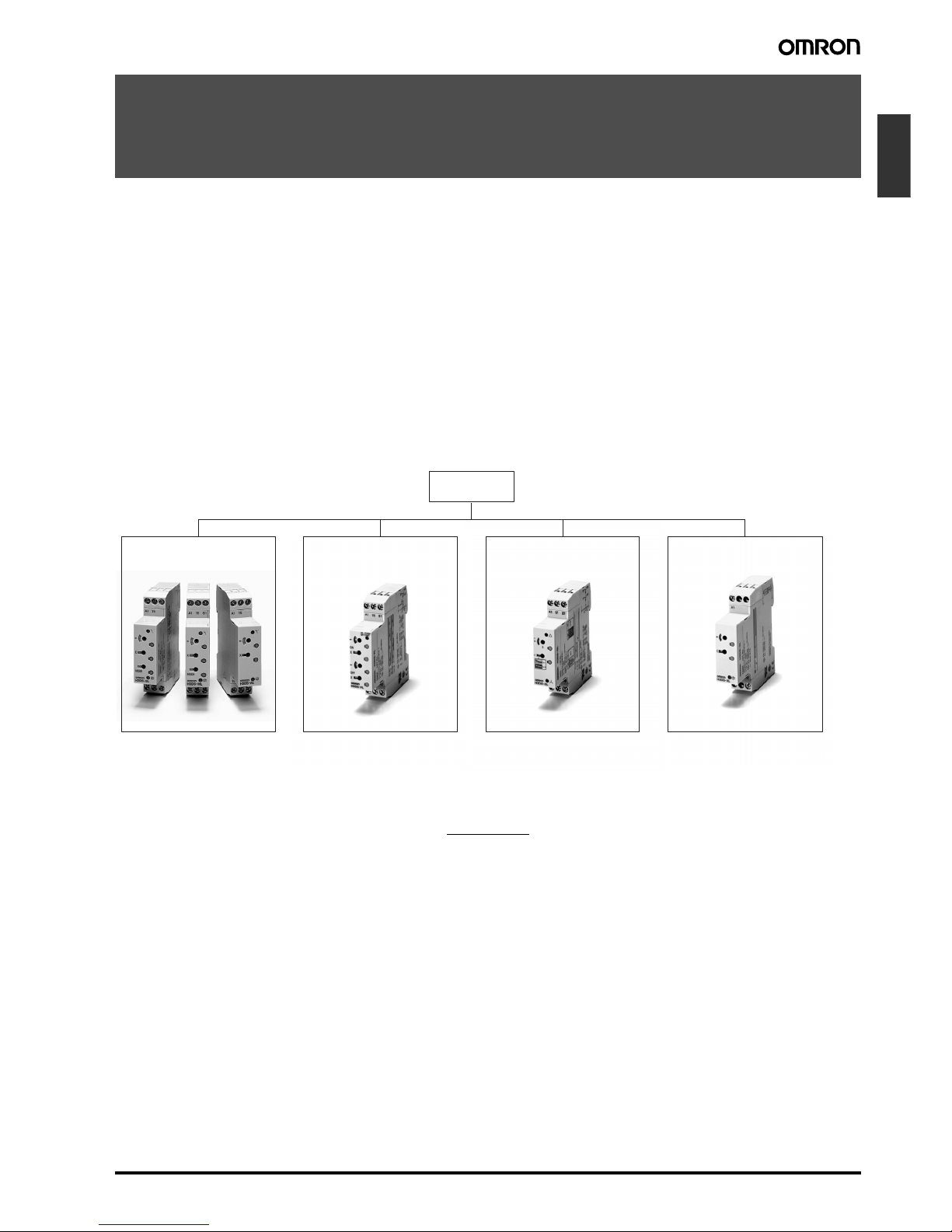
■ Broad Line-up of H3DS Series
Contents
Solid-state Timer
H3DS-M/-S/-A........................................................................................... 11
H3DS-F..................................................................................................... 23
H3DS-G.................................................................................................... 31
H3DS-X .................................................................................................... 39
Common to ALL Timers
Installation of Screw-Less Clamp Models................................................. 45
Accessories .............................................................................................. 47
Precautions............................................................................................... 48
H3DS-M/S/A
Standard Timer
H3DS-M (eight multi-modes)
H3DS-S (four multi-modes)
H3DS-A (single mode)
Twin Timer
H3DS-F
Star-delta Timer
H3DS-G
Two-wired Timer
H3DS-X
H3DS-F H3DS-G
H3DS
H3DS-X
Page 2

B-10 Solid-state Timer H3DS
Page 3
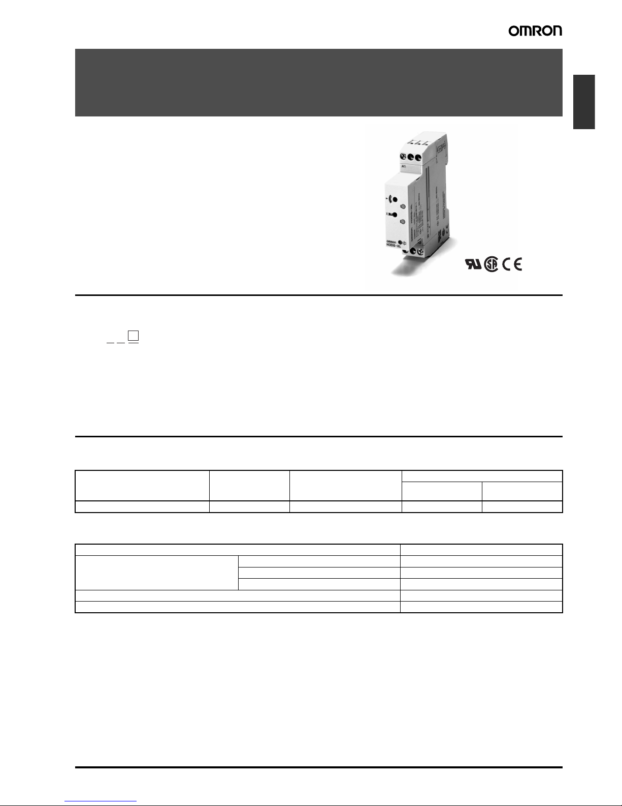
Solid-state Multi-functional Timer H3DS-M/-S/-A B-11
Timers
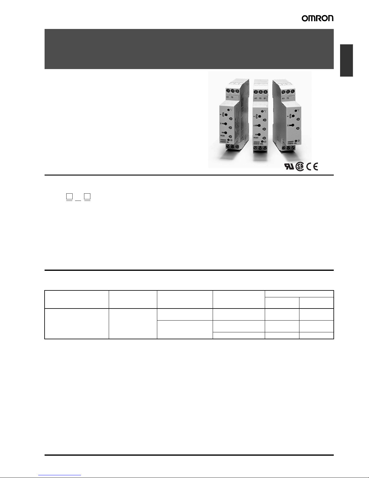
Solid-state Multi-functional Timer
H3DS-M/-S/-A
• Eight operating modes (H3DS-M) and four operating modes
(H3DS-S) cover a wide range of applications.
• A wide time setting range of 0.10 s to 120 h.
• Two LEDs indicate power and relay status
respectively.
Model Number Structure
■ Model Number Legend
Ordering Information
■ List of Models
Note: The operating modes are as follows:
A: ON-delay
B: Flicker OFF start
B2: Flicker ON start
C: Signal ON/OFF-delay
D: SIgnal OFF-delay
E: Interval
G: Signal ON/OFF-delay
J: One shot
1 2 3
H3DS - L
1. M: Multi-function type
S: Standard type
A: Single-function type
2. L: Smart lock mechanism
3. None: Screw terminal type
C: Screw-Less Clamp type
Supply voltage Control output Input type Operating mode
(see note)
Model
Screw terminal
type
Screw-Less
Clamp type
24 to 230 VAC (50/60Hz)/
24 to 48 VDC
Contact output: SPDT
(time-limit output SP-
DT)
Voltage input Eight multi-modes: A, B,
B2, C, D, E, G, J
H3DS-ML H3DS-MLC
No-input available Four multi-modes: A, B2,
E, J
H3DS-SL H3DS-SLC
Single mode: A H3DS-AL H3DS-ALC
Page 4

B-12 Solid-state Multi-functional Timer H3DS-M/-S/-A
■ Accessories (Order Separately)
Lock Key Y92S-38
Mounting Track 50 cm (l) x 7.3 mm (t) PFP-50N
1 m (l) x 7.3 mm (t) PFP-100N
1 m (l) x 16 mm (t) PFP-100N2
End Plate PFP-M
Spacer PEP-S
Page 5
Solid-state Multi-functional Timer H3DS-M/-S/-A B-13
Timers
Specifications
■ General
Note: Can be mounted to 35-mm DIN Track with a plate thickness of 1 to 2.5 mm.
■ Time Ranges
Note: When the time setting dial is set to “0” for any time scale, the output will operate instantaneously.
■ Ratings
Note: 1. DC ripple rate: 20% max.
2. Since an inrush current of 0.5 A will occur when using the power supply voltage at 24 VDC, pay careful attention when turning on or off
the power supply to the Timer with a solid-state output such as a sensor.
3. The power consumption is for mode A after the Timer counts the time-up time and for the AC input at 50 Hz. The power consumption of
the H3DS-ML includes the input circuit with the B1 and A1 terminals short-circuited.
Item H3DS-ML@ H3DS-SL@ H3DS-AL@
Operating mode A: ON-delay (Signal or Power)
B: Flicker OFF start (Signal or Power)
B2: Flicker ON start (Signal or Power)
C: Signal ON/OFF-delay
D: Signal OFF-delay
E: Interval (Signal or Power)
G: Signal ON/OFF-delay
J: One-shot (Signal or Power)
A: ON-delay
B2: Flicker ON start
E: Interval
J: One-shot
A: ON-delay (fixed)
Input type Voltage input ---
Output type Relay: SPDT
External connections Screw terminal, Screw-Less Clamp
Terminal block
Screw terminal type: Clamps two 2.5-mm
2
max. bar terminals without sleeves.
Screw-Less Clamp type: Clamps two 1.5-mm
2
max. bar terminals without sleeves.
Terminal screw
tightening torque
0.98 N·m max.
Mounting method DIN track mounting (see note)
Attachment Nameplate label
Approved standards UL508, CSA C22.2 No.14
Conforms to EN61812-1, IEC60664-1 4 kV/2, VDE0106/P100
Output category according to IEC60947-5-1 (AC-13; 250 V 5 A/AC-14; 250 V 1 A/AC-15; 250 V 1 A/DC-13; 30 V 0.1 A/
DC-14; 30 V 0.05 A)
Time scale display Time range
0.1 s 0.1 to 1.2 s
1 s 1 to 12 s
0.1 m 0.1 to 1.2 min
1 m 1 to 12 min
0.1 h 0.1 to 1.2 h
1 h 1 to 12 h
10 h 10 to 120 h
Rated supply voltage
(see notes 1 and 2)
24 to 230 VAC (50/60 Hz)/24 to 48 VDC
Operating voltage range 85% to 110% of rated supply voltage
Power reset Minimum power-off time: 0.1 s
Reset voltage 2.4 VAC/DC max.
Power consumption (see note 3) AC: 32 VA max./3.0 W max. (typical: 30 VA/2.7 W) at 230 VAC
14 VA max./2.2 W max. (typical: 13 VA/2.1 W) at 100 to 120 VAC
DC: 0.7 W max. (typical: 0.6 W) at 24 VDC
1.4 W max. (typical: 1.3 W) at 48 VDC
Voltage input Max. permissible capacitance between inputs lines (terminals B1 and A2): 2,000 pF
Load connectable in parallel with inputs (terminals B1 and A1).
H-level: 20.4 to 253 VAC/20.4 to 52.8 VDC
L-level: 0 to 2.4 VAC/DC
Control output Contact output: 5 A at 250 VAC with resistive load (cosφ = 1)
5 A at 30 VDC with resistive load (cosφ = 1)
Ambient temperature Operating: –10°C to 55°C (with no icing)
Storage: –25°C to 65°C (with no icing)
Ambient humidity Operating: 35% to 85%
Page 6
B-14 Solid-state Multi-functional Timer H3DS-M/-S/-A
■ Characteristics
Note: For reference:
A maximum current of 0.15 A can be switched at 125 VDC (cosφ=1).
A maximum current of 0.1 A can be switched if L/R is 7 ms.
In both cases, a life of 100,000 operations can be expected.
The minimum applicable load is 10 mA at 5 VDC (failure level: P).
Accuracy of operating time ±1% max. of FS (±1% ±10 ms max. at 1.2-s range)
Setting error ±10% ±50 ms max. of FS
Signal input time 50 ms min.
Influence of voltage ±0.7% max. of FS (±0.7% ±10 ms max. at 1.2-s range)
Influence of temperature ±5% max. of FS (±5%±10 ms max. at 1.2-s range)
Insulation resistance 100 MΩ min. at 500 VDC
Dielectric strength Between current-carrying metal parts and exposed non-current-carrying metal parts: 2,000 VAC for 1 min.
Between control output terminals and operating circuit: 2,000 VAC for 1 min.
Between contacts not located next to each other: 1,000 VAC for 1 min.
Vibration resistance Malfunction: 0.5-mm single amplitude at 10 to 55 Hz
Destruction: 0.75-mm single amplitude at 10 to 55 Hz
Shock resistance
Malfunction: 100 m/s
2
3 times each in 6 directions
Destruction: 1,000 m/s
2
3 times each in 6 directions
Impulse withstand voltage 3 kV (between power terminals)
4.5 kV (between current-carrying metal parts and exposed non-current-carrying metal parts)
Noise immunity Square-wave noise generated by noise simulator (pulse width: 100 ns/1 µs, 1-ns rise) ±1.5 kV
Static immunity Malfunction: 4 kV
Destruction: 8 kV
Life expectancy Mechanical: 10 million operations min. (under no load at 1,800 operations/h)
Electrical: 100,000 operations min. (5 A at 250 VAC, resistive load at 360 operations/h)
(see note)
EMC (EMI) EN61812-1
Emission Enclosure: EN55011 Group 1 class B
Emission AC Mains: EN55011 Group 1 class B
Harmonic Current: EN61000-3-2
Voltage Fluctuation and Flickering: EN61000-3-3
(EMS) EN61812-1
Immunity ESD: EN61000-4-2: 6 kV contact discharge (level 3)
8 kV air discharge (level 3)
Immunity RF-interference from AM Radio Waves:
EN61000-4-3: 10 V/m (80 MHz to 1 GHz) (level 3)
Immunity Burst: EN61000-4-4: 2 kV power port and output port (level 3)
1 kV control port with capacitive clamp (level 3)
Immunity Surge: EN61000-4-5: 2 kV common mode (level 3)
1 kV differential mode (level 3)
Case color Light gray (5Y7/1)
Degree of protection IP30 (Terminal block: IP20)
Weight Approx. 70 g
Page 7
Solid-state Multi-functional Timer H3DS-M/-S/-A B-15
Timers
Connections
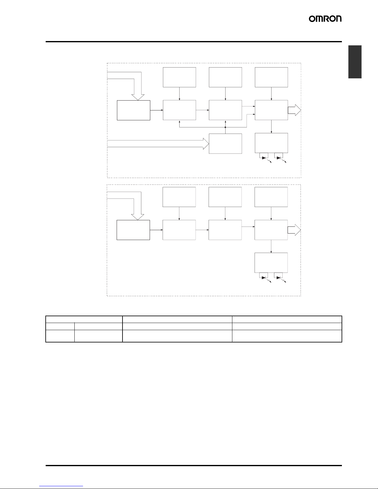
■ Block Diagram
■ I/O Functions
H3DS-ML@
AC (DC) input
Start input Input circuit
Zero setting
detection
circuit
Time scale/
unit selectors
Power supply
circuit
Oscillation
circuit
Counting
circuit
Indicator
circuit
Power-ON
indicator
Output
indicator
Output circuit
Operating
mode selector
H3DS-SL@/-AL@
AC (DC) input
Zero setting
detection
circuit
Time scale/
unit selectors
Power supply
circuit
Oscillation
circuit
Counting
circuit
Power-ON
indicator
Output
indicator
Indicator
circuit
Output circuit
Operating
mode selector
Item H3DS-ML@ H3DS-SL@/-AL@
Input Start Starts operation. No input is available.
Output Control output Outputs are turned ON according to designated out-
put mode when preset value is reached.
Outputs are turned ON according to designated output mode when preset value is reached.
Page 8
B-16 Solid-state Multi-functional Timer H3DS-M/-S/-A
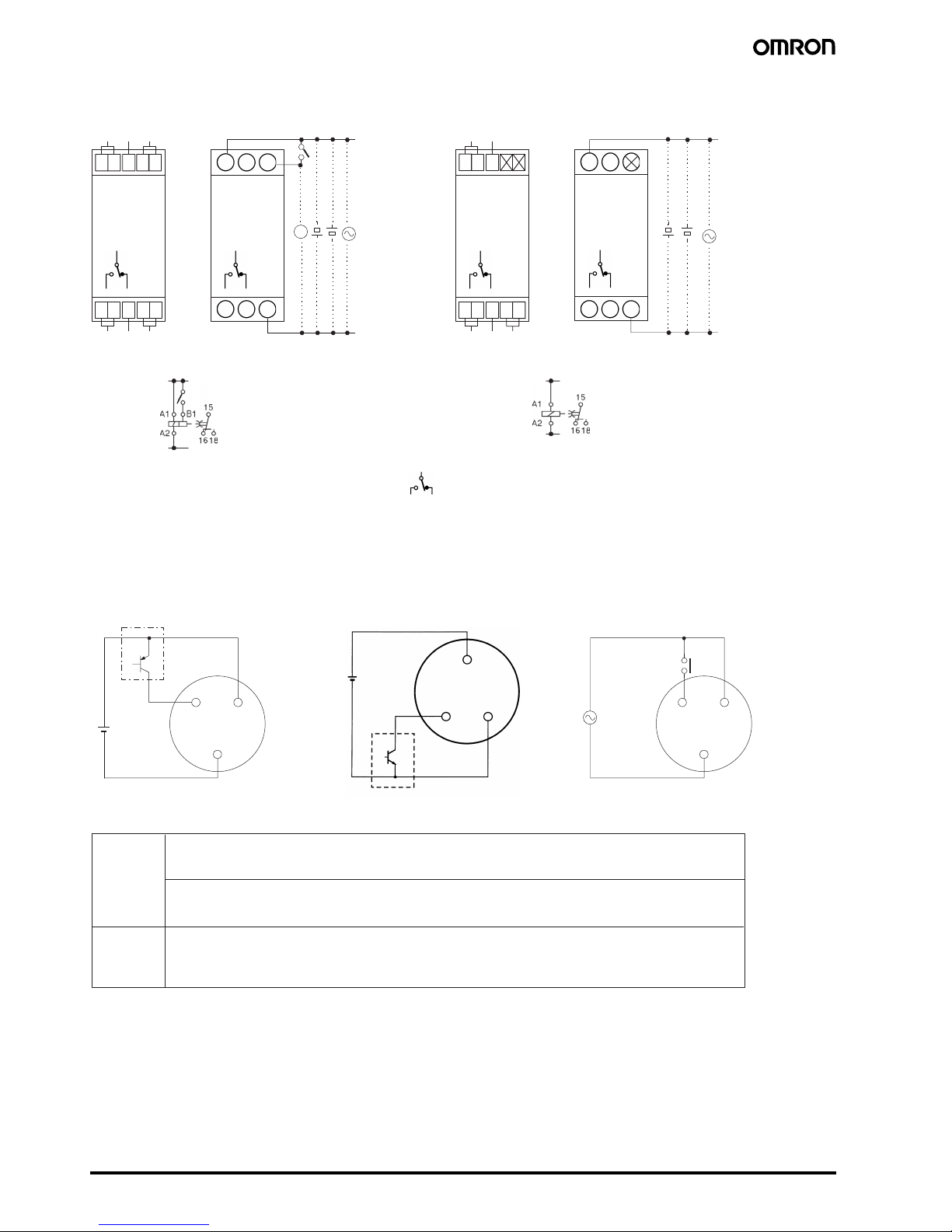
■ Terminal Arrangement
Note: 1. DC supply voltage does not require the designation of polarity.
2. The contact symbol for the H3DS is indicated with because it offers multiple operating modes and is different from the delayed
contact for conventional timers.
■ Input Connections
The inputs of the H3DS-ML@ are voltage (voltage imposition or open) inputs.
A1A115 A1 15
15 A1 15
15
18 16
18 16 A2 18 16 A2
A2
L
18 16
18 16 A218 16
15
18 16
15
18 16
15
B1
B1
H3DS-MLC
(see note 1) (see note 1)
H3DS-ML H3DS-SLC/-ALC H3DS-SL/-AL
(DIN notation) (DIN notation)
(+)
(−)
(+)
(−)
A
1
A1
A1
A2
A2
A2
B1
No-contact Input
(Connection to PNP output sensor.)
No-contact Input
(Connection to NPN output sensor.)
Contact Input
Sensor
Sensor
Operates with PNP transistor ON
Operates with NPN transistor ON
Operates with relay ON
Timer
Timer
Timer
24 VDC
24 VDC
B
1
Start
B
1
Start
Voltage Input Signal Levels
No-contact
input
1. Transistor ON
Residual voltage: 1 V max.
(Voltage between terminals B
1 and A2 must be more than the rated "H-level" voltage (20.4 VDC min.).)
2. Transistor OFF
Leakage current: 0.01 mA max.
(Voltage between terminals B
1 and A2 must be less than the rated "L-level" voltage (2.4 VDC max.).)
Use contacts that can adequately switch 0.1 mA at each voltage to be imposed. (When the contacts are
ON or OFF, voltage between terminals B
1 and A2 must be within the following ranges:
When contacts are ON: 20.4 to 253 VAC/20.4 to 52.8 VDC
When contacts are OFF: 0 to 2.4 VAC/DC
Contact
input
Page 9
Solid-state Multi-functional Timer H3DS-M/-S/-A B-17
Timers
Operation
■ Basic Operation
Setting of Selector
The selectors can be turned clockwise and counterclockwise to
select the desired time scale, or operating mode.
Each selector has a snap mechanism that secures the selector at a
given position. Set the selector at a position at which it is secured. Do
not set it midway between two securing positions or a malfunction
could result from improper setting.
Selection of Operating Mode (except
for H3DS-AL)
The H3DS-ML/-SL can be set to any one of the operating modes A to
J. Turn the operating mode selector with a screwdriver until the
desired operating mode appears in the operating mode display window.
H3DS-ML (8 modes): A, B, B2, C, D, E, G, J
(In order of appearance)
H3DS-SL (4 modes): A, E, B2, J, E, E, J, J
(In order of appearance)
Note: Letters that appear more than once indicate exactly the same
operating mode.
Selection of Time Scale
The time scale is selected by turning the time scale selector. The
time scales will appear in the following order in the time scale display
window on the left of the selector:
1 s, 0.1 s, 1 h, 0.1 h, 10 h, 1 h, 1 m, 0.1 m.
Note: The time scale “1h” appears twice. Both instances indicate ex-
actly the same time scale.
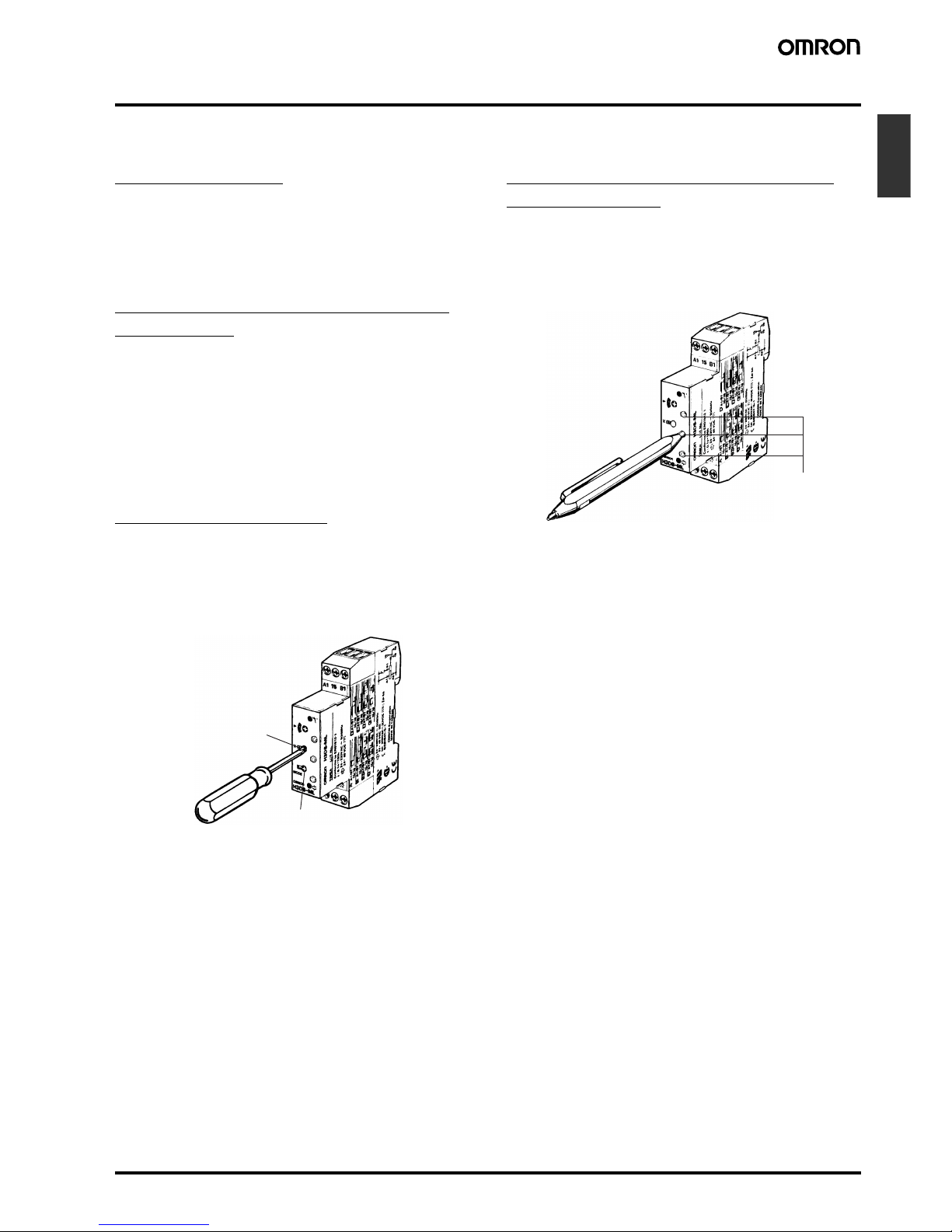
Locking/Unlocking of Selectors and
Time Setting Dial
The time setting dial, time scale selector, and operating mode selector can be locked using the Y92S-38 Lock Key, a special pen type
tool that is sold separately. To lock the dial or selectors, insert the
Lock Key in the keyhole to the lower right of the dial or selector and
turn it clockwise until the dial or selector is completely covered with
the red cover. To unlock, turn the Lock Key in the opposite direction.
Time scale display
window and selector
Operating mode display
window and selector
Key hole
Page 10
B-18 Solid-state Multi-functional Timer H3DS-M/-S/-A
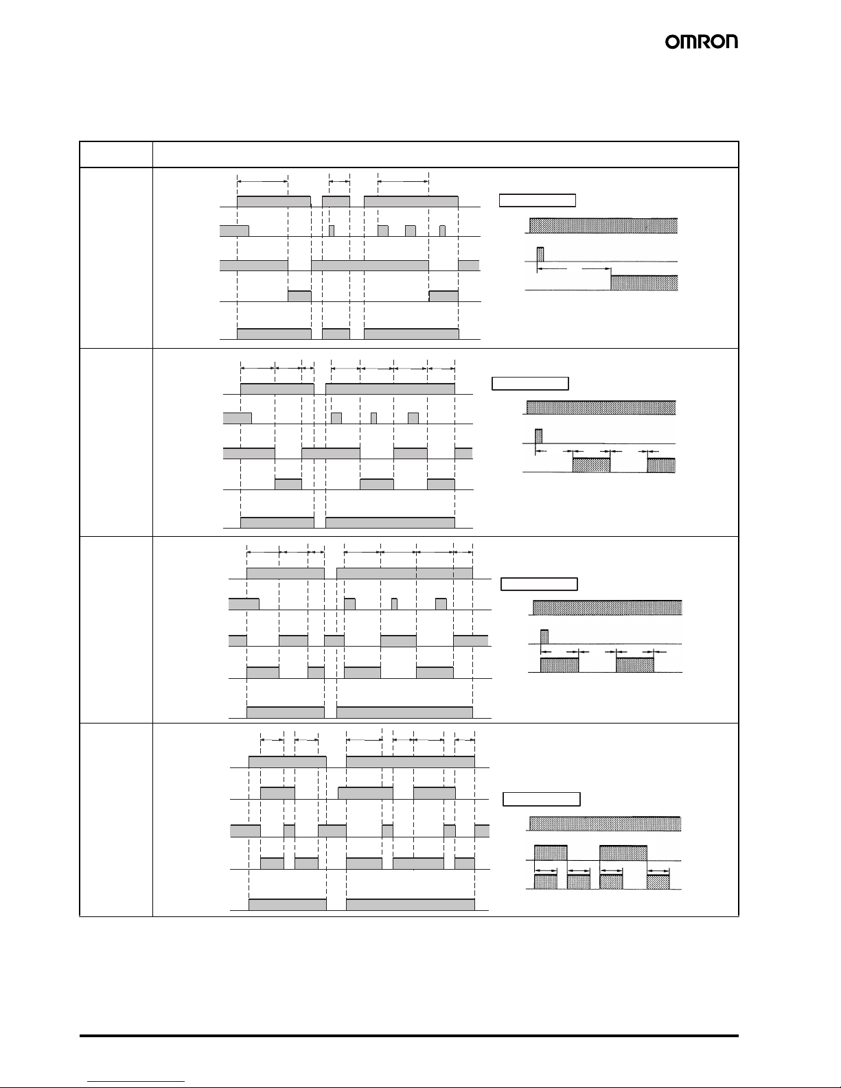
■ Timing Chart
Note: 1. The minimum power reset time is 0.1 s and the minimum signal input time is 0.05 s.
2. The letter “t” in the timing charts stands for the set time and “t–a” means that the period is less than the time set.
3. There is no start input for H3DS-SL@/-AL@ models. Operation starts at power-on.
Note: The start input of the H3DS-ML@ model is activated by applying a voltage to B1 and A2 terminals.
The voltage can be applied by turning on the contact between B1 and A1 (Refer to Terminal Arrangement).
Operating
mode
Timing chart
A: ON-delay
B:
Flicker OFF
start
B2:
Flicker ON
start
C:
Signal
ON/OFFdelay
**
*
Power (A
1
and A2)
Start (B
1
and A2)
(see note)
Output relay: NC
15 and 16
Power indicator
Output relay: NO
(output indicator)
15 and 18
tt–a
Power
* For power-on operation, impose voltage to the
Start input. The Timer starts operating at the
moment the power is turned on.
** Start input is invalid while the Timer is in opera -
tion.
Start
Output
Basic operation
t
t
*
**
Power (A
1
and A2)
Power indicator
ttt–a t–a
Basic operation
Power
Output
* For power-on operation, impose voltage to the
Start input. The Timer starts operating at the
moment the power is turned on.
** Start input is invalid while the Timer is in opera -
tion.
Start
tt tt
tt t
Start (B1 and A2)
(see note)
Output relay: NC
15 and 16
Output relay: NO
(output indicator)
15 and 18
*
**
Power (A
1
and A2)
tt tt–a t–a
Basic operation
Power
Output
* For power-on operation, impose voltage to the
Start input. The Timer starts operating at the
moment the power is turned on.
** Start input is invalid while the Timer is in opera -
tion.
Start
t
ttt
tt
Start (B1 and A2)
(see note)
Output relay: NC
15 and 16
Output relay: NO
(output indicator)
15 and 18
Power indicator
*
Power (A
1
and A2)
Power indicator
tt t tt–a t–a
Basic operation
Power
Start
Output
* Start input is invalid while the Timer is in opera -
tion.
ttt t
Start (B
1
and A2)
(see note)
Output relay: NC
15 and 16
Output relay: NO
(output indicator)
15 and 18
Page 11

Solid-state Multi-functional Timer H3DS-M/-S/-A B-19
Timers
Note: The start input of the H3DS-ML@ model is activated by applying a voltage to B1 and A2 terminals.
The voltage can be applied by turning on the contact between B1 and A1 (Refer to Terminal Arrangement).
Operating
mode
Timing chart
D:
Signal
OFF-delay
E: Interval
G:
Signal
ON/OFFdelay
J:
One-shot output
(ON delay)
*
Power (A
1
and A2)
ttt–a t–a t–a
Basic operation
Power
Output
* Start input is valid and re-triggerable while the
Timer is in operation.
Start
t
Power indicator
Start (B
1
and A2)
(see note)
Output relay: NC
15 and 16
Output relay: NO
(output indicator)
15 and 18
**
*
Power (A1 and A2)
tt tt–at–a
Basic operation
Power
Output
* For power-on operation, impose voltage to the
Start input. The Timer starts operating at the
moment the power is turned on.
** Start input is valid and re-triggerable while the
Timer is in operation.
Start
t
Power indicator
Start (B
1
and A2)
(see note)
Output relay: NC
15 and 16
Output relay: NO
(output indicator)
15 and 18
*
Power (A
1
and A2)
Power indicator
tt tt–a t–a t–a
Basic operation
Power
Output
* Start input is valid and re-triggerable while the
Timer is in operation.
Start
ttt t
tt
Start (B1 and A
2
)
(see note)
Output relay: NC
15 and 16
Output relay: NO
(output indicator)
15 and 18
**
*
Power (A
1
and A2)
t t t–a t–a t
t
Basic operation
Power
Output
* For power-on operation, impose voltage to the
Start input. The Timer starts operating at the
moment the power is turned on.
** Start input is valid and re-triggerable while the
Timer is in operation.
Start
Power indicator
Start (B
1
and A2)
(see note)
Output relay: NC
15 and 16
Output relay: NO
(output indicator)
15 and 18
Approx.
1±0.6 s
(fixed)
Approx.
1±0.6 s
(fixed)
Approx.
1±0.6 s
(fixed)
Approx. 1±0.6 s
(fixed)
Page 12
B-20 Solid-state Multi-functional Timer H3DS-M/-S/-A
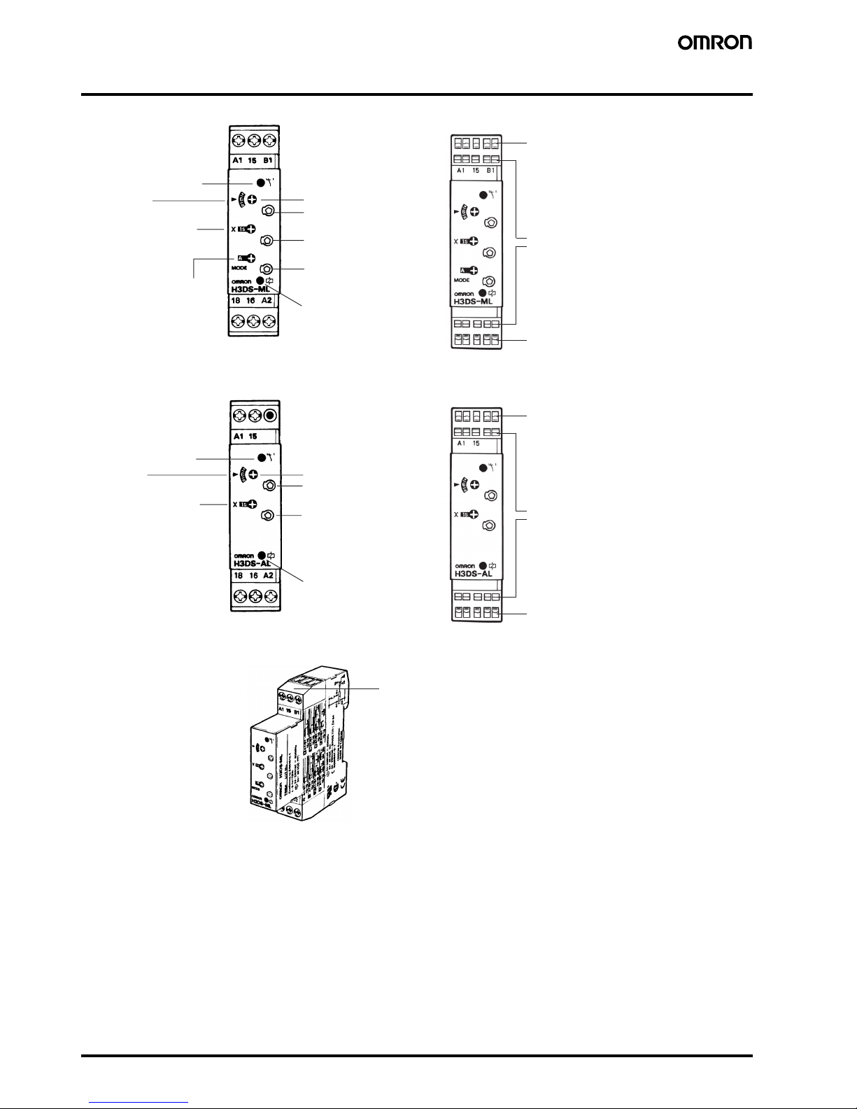
Nomenclature
18 16 A2
18 16 A2
H3DS-ML@/-SL@
H3DS-AL@
H3DS-ALC
Output indicator (orange)
(Lit while Timer output is ON.)
Output indicator (orange)
(Lit while Timer output is ON.)
Time scale display window and
selector (select one from 1 s,
0.1 s, 1 h, 0.1 h, 10 h, 1 h, 1 m,
and 0.1 m)
Set time window
Set time window
Time setting dial (set time)
Lock for time setting dial
Lock for time scale selector
Power-ON indicator (green)
(Lit while the power is ON.)
Attach the enclosed label here as a nameplate.
(The label is attached to the Timer's DIN Track
hook section at the time of shipment.)
Time setting dial (set time)
Lock for time setting dial
Lock for time scale selector
Lock for operating mode selector
Wire connection holes
Release holes
Wire connection holes
Wire connection holes
Release holes
Wire connection holes
Power-ON indicator (green)
(Lit while the power is ON.)
(Front View)
(Front View)
(Front View)
(Front View)
Time scale display window and
selector (select one from 1 s,
0.1 s, 1 h, 0.1 h, 10 h, 1 h, 1 m,
and 0.1 m)
Operating mode display window
and selector (select the mode from
A, B, B2, C, D, E, G, and J for the
H3DS-ML, from A, B2, E, and J for
the H3DS-SL)
H3DS-MLC/-SLC
Page 13
Solid-state Multi-functional Timer H3DS-M/-S/-A B-21
Timers
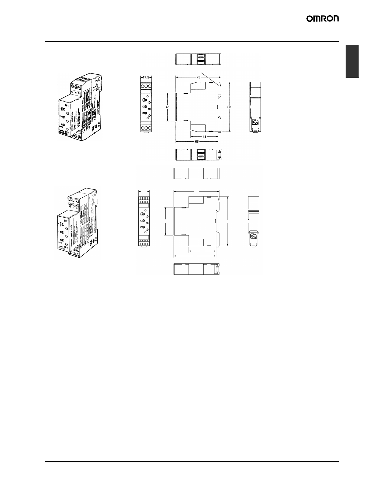
Dimensions
Note: All units are in millimeters unless otherwise indicated.
17.5 73
45
80
44
68
H3DS-ML/-SL/-AL
Surface color: Light gray 5Y7/1 (OMRON)
H3DS-MLC/-SLC/-ALC
Page 14

B-22 Solid-state Multi-functional Timer H3DS-M/-S/-A
Page 15

Solid-state Twin Timer H3DS-F B-23
Timers
Solid-state Twin Timer
H3DS-F
• Operates in flicker-OFF or flicker-ON start mode with one Unit.
• Independent ON- and OFF-time settings.
Combinations of long ON- or OFF-time and short OFF- or ONtime setting are possible.
• Long time range from 0.1 s to 12 h for both ON and OFF time
settings.
Model Number Structure
■ Model Number Legend
Ordering Information
■ List of Models
■ Accessories (Order Separately)
123
H3DS -F L
1. F: Twin timers
2. L: Smart lock mechanism
3. None: Screw terminal type
C: Screw-Less Clamp type
Operating mode Supply voltage Model
Screw terminal type Screw-Less Clamp type
Flicker-OFF/Flicker-ON start 24 to 230 VAC (50/60 Hz)/24 to 48 VDC H3DS-FL H3DS-FLC
Lock Key Y92S-38
Mounting Track 50 cm (l) x 7.3 mm (t) PFP-50N
1 m (l) x 7.3 mm (t) PFP-100N
1 m (l) x 16 mm (t) PFP-100N2
End Plate PFP-M
Spacer PEP-S
Page 16

B-24 Solid-state Twin Timer H3DS-F
Specifications
■ General
Note: Can be mounted to 35-mm DIN Track with a plate thickness of 1 to 2.5 mm.
■ Time Ranges
Note: When the time setting dial is set to “0” for any time scale, the output will operate instantaneously.
■ Ratings
Note: DC ripple rate: 20% max.
Item H3DS-F
Operating mode Flicker-OFF/Flicker-ON start
Output type Relay: SPDT
External connections Screw terminal, Screw-Less Clamp
Terminal block
Screw terminal type: Clamps two 2.5-mm
2
max. bar terminals without sleeves.
Screw-Less Clamp type: Clamps two 1.5-mm
2
max. bar terminals without sleeves.
Terminal screw tightening torque 0.98 N·m max.
Mounting method DIN track mounting (see note)
Attachment Nameplate label
Approved standards UL508, CSA C22.2 No.14
Conforms to EN61812-1, IEC60664-1 4 kV/2, VDE0106/P 100
Output category according to IEC60947-5-1 (AC-13; 250 V 5A/AC-15; 250 V 1 A/DC-13; 30 V 0.1 A)
Time scale display Time range
0.1 s 0.1 to 1.2 s
1 s 1 to 12 s
0.1 m 0.1 to 1.2 min
1 m 1 to 12 min
0.1 h 0.1 to 1.2 h
1 h 1 to 12 h
Rated supply voltage (See note.) 24 to 230 VAC (50/60 Hz)/24 to 48 VDC
Operating voltage range 85% to 110% of rated supply voltage
Power reset Minimum power-off time: 0.1 s
Reset voltage 2.4 VAC/DC max.
Power consumption AC: 33 VA max./2.2 W max. (typical: 31 VA/2.0 W) at 230 VAC
11 VA max./1.9 W max. (typical: 9.7 VA/1.7 W) at 100 to 120 VAC
DC: 0.7 W max. (typical: 0.6 W) at 24 VDC
1.4 W max. (typical: 1.2 W) at 48 VDC
Voltage input Max. permissible capacitance between inputs lines (terminals B1 and A2): 2,000 pF
Load connectable in parallel with inputs (terminals B1 and A1).
H-level: 20.4 to 253 VAC/20.4 to 52.8 VDC
L-level: 0 to 2.4 VAC/DC
Control output Contact output: 5 A at 250 VAC with resistive load (cosφ = 1)
5 A at 30 VDC with resistive load (cosφ = 1)
Ambient temperature Operating: –10°C to 55°C (with no icing)
Storage: –25°C to 65°C (with no icing)
Ambient humidity Operating: 35% to 85%
Page 17

Solid-state Twin Timer H3DS-F B-25
Timers
■ Characteristics
Note: For reference:
A maximum current of 0.15 A can be switched at 125 VDC (cosφ=1).
A maximum current of 0.1 A can be switched if L/R is 7 ms.
In both cases, a life of 100,000 operations can be expected.
The minimum applicable load is 10 mA at 5 VDC (failure level: P).
Accuracy of operating time ±1% max. of FS (±1% ±10 ms max. at 1.2-s range)
Setting error ±10% ± 50 ms max. of FS
Influence of voltage ±0.5% max. of FS (±0.5% ±10 ms max. at 1.2-s range)
Influence of temperature ±5% max. of FS (±5% ± 10 ms max. at 1.2-s range)
Insulation resistance 100 MΩ min. at 500 VDC
Dielectric strength Between current-carrying metal parts and exposed non-current-carrying metal parts: 2,000 VAC (50/60 Hz) for 1
min.
Between control output terminals and operating circuit: 2,000 VAC (50/60 Hz) for 1 min.
Between contacts not located next to each other: 1,000 VAC (50/60 Hz) for 1 min.
Impulse withstand voltage 3 kV (between power supply terminals)
4.5 kV (between current-carrying metal parts and exposed non-current-carrying metal parts)
Noise immunity Square-wave noise generated by noise simulator (pulse width: 100 ns/1 µs, 1-ns rise) ±1.5 kV
Static immunity Malfunction: 4 kV
Destruction: 8 kV
Vibration resistance Malfunction: 0.5-mm single amplitude at 10 to 55 Hz
Destruction: 0.75-mm single amplitude at 10 to 55 Hz
Shock resistance
Malfunction: 200 m/s
2
, 3 times each in 6 directions
Destruction: 300 m/s
2
, 3 times each in 6 directions
Life expectancy Mechanical: 10 million operations min. (under no load at 1,800 operations/h)
Electrical: 100,000 operations min. (5 A at 250 VAC, resistive load at 360 operations/h) (see note)
EMC (EMI) EN61812-1
Emission Enclosure: EN55011 Group 1 class B
Emission AC Mains: EN55011 Group 1 class B
Harmonic Current: EN61000-3-2
Voltage Fluctuation and Flickering: EN61000-3-3
(EMS) EN61812-1
Immunity ESD: EN61000-4-2: 6 kV contact discharge (level 3)
8 kV air discharge (level 3)
Immunity RF-interference from AM Radio Waves:
EN61000-4-3: 10 V/m (80 MHz to 1 GHz) (level 3)
Immunity Burst: EN61000-4-4: 2 kV power port and output port (level 3)
1 kV control port with capacitive clamp (level 3)
Immunity Surge: EN61000-4-5: 2 kV common mode (level 3)
1 kV differential mode (level 3)
Case color Light gray (5Y7/1)
Degree of protection IP30 (IP20 for terminal block)
Weight Approx. 70 g
Page 18

B-26 Solid-state Twin Timer H3DS-F
Connections
■ Block Diagram
■ I/O Function
■ Terminal Arrangement
Note: 1. If voltage is applied to terminal B1, or if terminals A1 and B1 are shorted, the operating mode is switched to flicker-ON start mode. If these
terminals are disconnected, the mode switches to flicker-OFF start mode.
2. DC supply voltage does not require the designation of polarity.
AC (DC)
input
ON
indicator
(Orange)
OFF
indicator
(Green)
ON/OFF start
selector
Indicator
circuit
One-chip microcomputer
ROM RAM Clock
Time scale
selector
Output
circuit
Power
supply
circuit
Inputs Flicker-ON start operation begins when inputs are turned ON.
Outputs Control output Outputs are turned ON/OFF according to the time set by the ON-and OFF-time setting dial.
A1 15
15
181816
16 A2
18 16 A2
15
L
18 16
B1
A1 15 B1
H3DS-FLC H3DS-FL
(See note 2.)
Page 19

Solid-state Twin Timer H3DS-F B-27
Timers
Operation
■ Basic Operation
Setting of Selector
The selectors can be turned clockwise and counterclockwise to
select the desired time scale, or operating mode.
Each selector has a snap mechanism that secures the selector at a
given position. Set the selector at a position at which it is secured. Do
not set it midway between two securing positions or a malfunction
could result from improper setting.
Settings for ON/OFF Start
If voltage is applied to terminal B1, or if terminals A1 and B1 are
shorted, the operating mode is switched to flicker-ON start mode. If
these terminals are disconnected, the mode switches to flicker-OFF
start mode. The operating mode will not change if the state of the
applied voltage changes during timer operation.
Selection of Time Scale
The time scale is selected by turning the ON-time scale selector and
OFF-time scale selector. The time scales will appear in the following
order in each time scale display window on the left of the selector:
0.1 s, 1 h, 0.1 h, 1 m, 1 s, 0.1 h, 0.1 m, 1 s.
Note: The time scales “1 s” and “0.1 h” appear twice. Both instances
indicate exactly the same time scale.
Time Setting
Use the ON/OFF-time setting dials to set the ON/OFF time.
Locking/Unlocking of Selectors and
Time Setting Dial
The ON/OFF-time setting dials and time scale selectors can be
locked using the Y92S-38 Lock Key, a special pen type tool that is
sold separately. To lock the dials or selectors, insert the Lock Key in
the keyhole to the lower right of the dial or selector and turn it clockwise until the dial or selector is completely covered with the red
cover. To unlock, turn the Lock Key in the opposite direction.
■ Timing Charts
Note: 1. If voltage is applied to terminal B1, or if terminals A1 and B1 are shorted, the operating mode is switched to flicker-ON start mode. If these
terminals are disconnected, the mode switches to flicker-OFF start mode.
2. The reset time requires a minimum of 0.1 s.
3. When power is supplied in flicker-ON start mode, the OFF indicator lights momentarily. This, however, has no effect on the performance
of the Timer.
ON-time scale
display window
and selector
OFF-time scale display
window and selector
Key hole
Operating
mode
Timing chart
Flicker-OFF
start
(See note 1.)
Flicker-ON
start
(See note 1.)
Power (A1 and A2)
Output relay: NO
15 and 18
(ON indicator)
Output relay: NC
15 and 16
OFF indicator
0.1 s min.
ON
OFF
ON
OFF
ON
OFF
ON
OFF
t
ON
: ON set time
t
OFF
: OFF set time
Power (A1 and A2)
0.1 s min.
ON
OFF
ON
OFF
ON
OFF
ON
OFF
ON
OFF
Signal (B
1
and A2)
Output relay: NO
15 and 18
(ON indicator)
Output relay: NC
15 and 16
t
ON
: ON set time
t
OFF
: OFF set time
OFF indicator
Page 20

B-28 Solid-state Twin Timer H3DS-F
Nomenclature
1618 A2
H3DS-FL@
H3DS-FLC
ON-time display window
OFF-time display window
(Front View)
(Front View)
ON-time scale display window
and selector (select one from
0.1 s, 1 s, 0.1 m, 1 m, 0.1 h,
and 1 h)
Output ON/OFF indicator
When the output is ON: Orange
When the output is OFF: Green
ON-time setting dial
Lock for ON-time setting dial
Lock for ON-time scale selector
OFF-time setting dial
Lock for OFF-time setting dial
Lock for OFF-time scale selector
Attach the enclosed label here as a nameplate.
(The label is attached to the Timer's DIN Track
hook section at the time of shipment.)
Wire connection holes
Wire connection holes
Release holes
OFF-time scale display window
and selector (select one from
0.1 s, 1 s, 0.1 m, 1 m, 0.1 h,
and 1 h)
Page 21

Solid-state Twin Timer H3DS-F B-29
Timers
Dimensions
17.5
17.5
73
73
45
45
80
80
44
44
68
68
H3DS-FL
H3DS-FLC
Surface color: Light gray 5Y7/1 (OMRON)
Surface color: Light gray 5Y7/1 (OMRON)
Page 22

B-30 Solid-state Twin Timer H3DS-F
Page 23

Solid-state Star-delta Timer H3DS-G B-31
Timers
Solid-state Star-delta Timer
H3DS-G
• A wide star-time range (up to 120 seconds) and star-delta transfer time range (up to 1 second)
Model Number Structure
■ Model Number Legend
Ordering Information
■ List of Models
■ Accessories (Order Separately)
1 2 3
H3DS -G L
1. G: Star-delta timer
2. L: Smart lock mechanism
3. None: Screw terminal type
C: Screw-Less Clamp type
Operating mode Supply voltage Model
Screw terminal type Screw-Less Clamp type
Star-delta operation 24 to 230 VAC (50/60 Hz)/24 to 48 VDC H3DS-GL H3DS-GLC
Lock Key Y92S-38
Mounting Track 50 cm (l) x 7.3 mm (t) PFP-50N
1 m (l) x 7.3 mm (t) PFP-100N
1 m (l) x 16 mm (t) PFP-100N2
End Plate PFP-M
Spacer PEP-S
Page 24

B-32 Solid-state Star-delta Timer H3DS-G
Specifications
■ General
Note: Can be mounted to 35-mm DIN Track with a plate thickness of 1 to 2.5 mm.
■ Time Ranges
■ Ratings
Note: DC ripple rate: 20% max.
Item H3DS-G
Operating mode Star-delta operation
Operating/Reset method Time-limit operation/Self-reset
External connections Screw terminal, Screw-Less Clamp
Terminal block
Screw terminal type: Clamps two 2.5-mm
2
max. bar terminals without sleeves.
Screw-Less Clamp type: Clamps two 1.5-mm
2
max. bar terminals without sleeves.
Terminal screw tightening torque 0.98 N·m max.
Output type (Star operation circuit) Relay: SPST-NO
(Delta operation circuit) Relay: SPST-NO
Mounting method DIN track mounting (see note)
Attachment Nameplate label
Approved standards UL508, CSA C22.2 No.14
Conforms to EN61812-1, IEC60664-1 4 kV/2, VDE0106/P100
Output category according to IEC60947-5-1 (AC-13; 250 V 5A/AC-15; 250 V 1 A/DC-13; 30 V 0.1 A)
Time scale Star operation time ranges
x 1 1 to 12 s
x 10 10 to 120 s
Star-delta transfer time Programmable at 0.05 s, 0.1 s, 0.5 s, or 1 s
Rated supply voltage (see note) 24 to 230 VAC (50/60 Hz)/24 to 48 VDC
Operating voltage range 85% to 110% of rated supply voltage
Power reset Minimum power-off time: 0.5 s
Reset voltage 2.4 VAC/DC max.
Power consumption AC: 21 VA max./1.7 W max. (typical: 20 VA/1.6 W) at 230 VAC
11 VA max./2.0 W max. (typical: 8.6 VA/1.5 W) at 100 to 120 VAC
DC: 1.3 W max. (typical: 1.2 W) at 24 VDC
0.7 W max. (typical: 0.6 W) at 48 VDC
Control output Contact output: 5 A at 250 VAC with resistive load (cosφ = 1)
5 A at 30 VDC with resistive load (cosφ = 1)
Ambient temperature Operating: –10°C to 55°C (with no icing)
Storage: –25°C to 65°C (with no icing)
Ambient humidity Operating: 35% to 85%
Page 25

Solid-state Star-delta Timer H3DS-G B-33
Timers
■ Characteristics
Note: For reference:
A maximum current of 0.15 A can be switched at 125 VDC (cosφ=1).
A maximum current of 0.1 A can be switched if L/R is 7 ms.
In both cases, a life of 100,000 operations can be expected.
The minimum applicable load is 10 mA at 5 VDC (failure level: P).
Accuracy of operating time ±1% max. of FS
Setting error ±10% ± 50 ms max. of FS
Total tolerance of transfer
time
± (25% FS + 5 ms) max.
Influence of voltage ±0.5% max. of FS
Influence of temperature ±5% max. of FS
Insulation resistance 100 MΩ min. at 500 VDC
Dielectric strength Between current-carrying metal parts and exposed non-current-carrying metal parts: 2,000 VAC (50/60 Hz) for 1
min.
Between control output terminals and operating circuit: 2,000 VAC (50/60 Hz) for 1 min.
Between contacts not located next to each other: 1,000 VAC (50/60 Hz) for 1 min.
Impulse withstand voltage 3 kV (between power supply terminals)
4.5 kV (between current-carrying metal parts and exposed non-current-carrying metal parts)
Noise immunity Square-wave noise generated by noise simulator (pulse width: 100 ns/1 µs, 1-ns rise) ±1.5 kV
Static immunity Malfunction: 4 kV
Destruction: 8 kV
Vibration resistance Malfunction: 0.5-mm single amplitude at 10 to 55 Hz
Destruction: 0.75-mm single amplitude at 10 to 55 Hz
Shock resistance
Malfunction: 200 m/s
2
, 3 times each in 6 directions
Destruction: 300 m/s
2
, 3 times each in 6 directions
Life expectancy Mechanical: 10 million operations min. (under no load at 1,800 operations/h)
Electrical: 100,000 operations min. (5 A at 250 VAC, resistive load at 360 operations/h) (see note)
EMC (EMI) EN61812-1
Emission Enclosure: EN55011 Group 1 class B
Emission AC Mains: EN55011 Group 1 class B
Harmonic Current: EN61000-3-2
Voltage Fluctuation and Flickering: EN61000-3-3
(EMS) EN61812-1
Immunity ESD: EN61000-4-2: 6 kV contact discharge (level 3)
8 kV air discharge (level 3)
Immunity RF-interference from AM Radio Waves:
EN61000-4-3: 10 V/m (80 MHz to 1 GHz) (level 3)
Immunity Burst: EN61000-4-4: 2 kV power port and output port (level 3)
1 kV control port with capacitive clamp (level 3)
Immunity Surge: EN61000-4-5: 2 kV common mode (level 3)
1 kV differential mode (level 3)
Case color Light gray (5Y7/1)
Degree of protection IP30 (IP20 for terminal block)
Weight Approx. 70 g
Page 26

B-34 Solid-state Star-delta Timer H3DS-G
Connections
■ Block Diagram
■ I/O Functions
■ Terminal Arrangement
Note: DC supply voltage does not require the designation of polarity.
AC (DC) input
Star
operation
time scale
selector
Power
supply
circuit Output
circuit
Indicator
circuit
Star operation
indicator
Delta operation
indicator
Star operation
Delta operation
Star opera tion time
oscillation
circuit
Star opera tion time
counting
circuit
Star-delta
transfer
time oscilla tion circuit
Star-delta
transfer
time
counting
circuit
Star-delta
transfer
time
selection
Inputs --Outputs Control output Star output is turned OFF when the dial set value is reached and delta output is ON after
the preset transfer time elapses
A1 17 27
A1 17 27
17
18 28
18 28 A2
18 28 A2
27 17
18 28
27
H3DS-GLC
(see note)
H3DS-GL
Page 27

Solid-state Star-delta Timer H3DS-G B-35
Timers
Operation
■ Basic Operation
Setting of Selector
The selectors can be turned clockwise and counterclockwise to
select the desired time scale, or operating mode.
Each selector has a snap mechanism that secures the selector at a
given position. Set the selector at a position at which it is secured. Do
not set it midway between two securing positions or a malfunction
could result from improper setting.
Selection of Time Unit and Time Scale
The star-delta transfer time and star operation time scale are set with
the same selector. The star-delta transfer time can be set to 0.05,
0.1, 0.5, or 1. The star operation time scale can be set to a multiplication factor of 1 or 10. If the star-delta transfer time is displayed in the
display window in white letters, this means that the star operation
time scale is “x10”. Refer to the example below.
Time Setting
The star operation time of the Timer is set with the time setting dial.
Locking/Unlocking of Selectors and
Time Setting Dial
The time setting dial and time scale selector can be locked using the
Y92S-38 Lock Key, a special pen type tool that is sold separately. To
lock the dial or selectors, insert the Lock Key in the keyhole to the
lower right of the dial or selector and turn it clockwise until the dial or
selector is completely covered with the red cover. To unlock, turn the
Lock Key in the opposite direction.
■ Timing Charts
Note: The reset time requires a maximum of 0.5 s.
Star-delta transfer time Star operation time scale
x1
x10
0.05 s
0.1 s
0.5 s
1 s
0.05 s
0.1 s
0.5 s
1 s
Star-delta transfer time and
star operation time scale
display window and selector
Key hole
Power (A1 and A2)
Star contact
17 and 18
(star indicator)
Delta contact
27 and 28
(delta indicator)
t
1
: Star operation time setting
t
2
: Star-delta transfer time
ON
OFF
ON
OFF
ON
OFF
0.5 s
t
1
t
2
Page 28

B-36 Solid-state Star-delta Timer H3DS-G
Nomenclature
18 28 A2
H3DS-GL@
Set time window
Delta operation indicator (orange)
Wire connection holes
Release holes
Wire connection holes
H3DS-GLC
Lock for time setting dial
Time setting dial (for setting
star operation time)
Lock for star-delta transfer time
and star operation time scale
Attach the enclosed label here as a nameplate.
(The label is attached to the Timer's DIN Track
hook section at the time of shipment.)
Star operation indicator
(green)
(Front View)
(Front View)
Star-delta transfer time and
star operation time scale
display window and selector
Page 29

Solid-state Star-delta Timer H3DS-G B-37
Timers
Dimensions
17.5
73
45
80
44
68
H3DS-GL
Surface color: Light gray 5Y7/1 (OMRON)
17.5
73
45
44
68
80
H3DS-GLC
Surface color: Light gray 5Y7/1 (OMRON)
Page 30

B-38 Solid-state Star-delta Timer H3DS-G
Page 31
Solid-state Two-wired Timer H3DS-X B-39
Timers
Solid-state Two-wired Timer
H3DS-X
• Covers wide range of supply voltage
(24 to 230 VAC/VDC).
Model Number Structure
■ Model Number Legend
Ordering Information
■ List of Models
■ Accessories (Order Separately)
1 2 3
H3DS -X L
1. X: Two-wired timer
2. L: Smart lock mechanism
3. None: Screw terminal type
C: Screw-Less Clamp type
Supply voltage Input type Operating mode Model
Screw terminal type Screw-Less Clamp
type
24 to 230 VAC/VDC (50/60 Hz) No-input available ON-delay H3DS-XL H3DS-XLC
Lock Key Y92S-38
Mounting Track 50 cm (l) x 7.3 mm (t) PFP-50N
1 m (l) x 7.3 mm (t) PFP-100N
1 m (l) x 16 mm (t) PFP-100N2
End Plate PFP-M
Spacer PEP-S
Page 32

B-40 Solid-state Two-wired Timer H3DS-X
Specifications
■ General
Note: Can be mounted to 35-mm DIN Track with a plate thickness of 1 to 2.5 mm.
■ Time Ranges
Note: When the time setting dial is set to “0” for any time scale, the output will operate instantaneously.
■ Ratings
Note: The ripple in DC power supply must be 5% max.
Item H3DS-X
Operating mode ON-delay
Operating/Reset method Time-limit operation/self-resetting
Output type SCR output
External connections Screw terminal, Screw-Less Clamp
Terminal block
Screw terminal type: Clamps two 2.5-mm
2
max. bar terminals without sleeves.
Screw-Less Clamp type: Clamps two 1.5-mm
2
max. bar terminals without sleeves.
Terminal screw tightening torque 0.98 N·m max.
Mounting method DIN track mounting (see note)
Attachment Nameplate label
Approved standards UL508, CSA C22.2 No.14
Conforms to EN61812-1, IEC60664-1 4 kV/2, VDE0106/P100
Time scale display Time range
0.1 s 0.1 to 1.2 s
1 s 1 to 12 s
0.1 m 0.1 to 1.2 min
1 m 1 to 12 min
0.1 h 0.1 to 1.2 h
1 h 1 to 12 h
10 h 10 to 120 h
Rated supply voltage (see note) 24 to 230 VAC/VDC (50/60 Hz)
Operating voltage range 85% to 110% of rated supply voltage
Power reset Minimum power-off time: 0.1 s
Reset voltage 1.0 VAC/VDC max.
Reset current 5 mA max.
Power consumption 5 mA max.
Control output SCR output:5 mA to 0.7 A
Ambient temperature Operating: –10°C to 55°C (with no icing)
Storage: –25°C to 65°C (with no icing)
Ambient humidity Operating: 35% to 85%
Page 33

Solid-state Two-wired Timer H3DS-X B-41
Timers
■ Characteristics
Connections
■ Block Diagram
■ I/O Functions
Accuracy of operating time ±1% max. of FS (±1% ±10 ms max. at 1.2-s range)
Setting error ±10% ± 50 ms max. of FS
Reset time 0.1 s max.
Influence of voltage ±0.5% max. of FS (±0.5%±10 ms max. at 1.2-s range)
Influence of temperature ±5% max. of FS (±5%±10 ms max. at 1.2-s range)
Insulation resistance 100 MΩ min. at 500 VDC
Dielectric strength Between current-carrying metal parts and exposed non-current-carrying metal parts: 2,000 VAC for 1 min
Impulse withstand voltage 3 kV (between power supply terminals)
4.5 kV (between current-carrying metal parts and exposed non-current-carrying metal parts)
Noise immunity Square-wave noise generated by noise simulator (pulse width: 100 ns/1 µs, 1-ns rise) ±1.5 kV (between power
supply terminals)
Static immunity Malfunction: 4 kV
Destruction: 8 kV
Vibration resistance Malfunction: 0.5-mm single amplitude at 10 to 55 Hz
Destruction: 0.75-mm single amplitude at 10 to 55 Hz
Shock resistance
Malfunction: 200 m/s
2
, 3 times each in 6 directions
Destruction: 300 m/s
2
, 3 times each in 6 directions
EMC (EMI) EN61812-1
Emission Enclosure: EN55011 Group 1 class B
Emission AC Mains: EN55011 Group 1 class B
Harmonic Current: EN61000-3-2
Voltage Fluctuation and Flickering: EN61000-3-3
(EMS) EN61812-1
Immunity ESD: EN61000-4-2: 6 kV contact discharge (level 3)
8 kV air discharge (level 3)
Immunity RF-interference from AM Radio Waves:
EN61000-4-3: 10 V/m (80 MHz to 1 GHz) (level 3)
Immunity Burst: EN61000-4-4: 2 kV power port and output port (level 3)
1 kV control port with capacitive clamp (level 3)
Immunity Surge: EN61000-4-5: 2 kV common mode (level 3)
1 kV differential mode (level 3)
Case color Light gray (5Y7/1)
Degree of protection IP30 (IP20 for terminal block)
Weight Approx. 70 g
AC (DC)
input
Power supply
circuit
Oscillation
circuit
Zero setting
detection
circuit
Counting
circuit
Time scale/
unit selectors
Indicator
circuit
Output
circuit
Inputs --Outputs Control output Outputs are turned ON when the preset value is reached.
Page 34

B-42 Solid-state Two-wired Timer H3DS-X
■ Terminal Arrangement
Note: DC supply voltage does not require the designation of polarity.
Operation
■ Basic Operation
Setting of Selector
The selectors can be turned clockwise and counterclockwise to
select the desired time scale, or operating mode.
Each selector has a snap mechanism that secures the selector at a
given position. Set the selector at a position at which it is secured. Do
not set it midway between two securing positions or a malfunction
could result from improper setting.
Selection of Time Scale
The time scale is selected by turning the time scale selector. The
time scales will appear in the following order in the time scale display
window on the left of the selector:
1 s, 0.1 s, 1 h, 0.1 h, 10 h, 1 h, 1 m, 0.1 m.
Note: The time scale “1h” appears twice. Both instances indicate ex-
actly the same time scale.
Locking/Unlocking of Selectors and
Time Setting Dial
The time setting dial and time scale selector can be locked using the
Y92S-38 Lock Key, a special pen type tool that is sold separately. To
lock the dial or selectors, insert the Lock Key in the keyhole to the
lower right of the dial or selector and turn it clockwise until the dial or
selector is completely covered with the red cover. To unlock, turn the
Lock Key in the opposite direction.
A1
A1
A2
A2
H3DS-XLC H3DS-XL
Time scale display
window and selector
Key hole
Page 35

Solid-state Two-wired Timer H3DS-X B-43
Timers
■ Timing Charts
Nomenclature
Power
(A1 and A2)
Output
Set time
Rt: Resetting time
Rt 0.1 s min.
Indicator
ON
OFF
A2
A2
H3DS-XL
H3DS-XL@
H3DS-XLC
Set time window
(Front View)
(Front View)
Time setting dial (set time)
Lock for time setting dial
Wire connection holes
Release holes
Wire connection holes
Lock for time scale selector
Power-ON indicator (green)
(Lit while the power is ON.)
Attach the enclosed label here as a nameplate.
(The label is attached to the Timer's DIN Track
hook section at the time of shipment.)
Time scale display window and
selector (select one from 1 s,
0.1 s, 1 h, 0.1 h, 10 h, 1 h, 1 m,
and 0.1 m)
Page 36

B-44 Solid-state Two-wired Timer H3DS-X
Dimensions
17.5
73
45
80
44
68
H3DS-XL
H3DS-XLC
Surface color: Light gray 5Y7/1 (OMRON)
Page 37

Common to All Timers H3DS-@LC B-45
Timers
Installation of Screw-Less Clamp Models
■ Tools
A flat-blade screwdriver should be used to mount the cables.
Applicable Screwdriver
● Flat-blade, Parallel-tip, 2.5 mm diameter
Examples: FACOM AEF.2.5 × 75E
VESSEL No. 9900-(-)2.5 × 75
WAGO 210-119
WIHA 260/2.5 × 40
■ Applicable Wires
Applicable Wire Sizes
0.2 to 1.5 mm2, AWG24 to AWG16
Applicable Wire Type
Solid wires, stranded wires, flexible wires, or wires with ferules can
be used.
(See note 1) < 1.8 ≤ Diameter D (mm) ≤ 3.0 (see note 2)
Conductor diameter d (mm) or length of sides a and b (mm) ≤ 1.6
Note: 1. If the overall diameter of the wire is less than 1.8 mm, do not
insert the wire past the conductor. Refer to the following diagrams.
2. If the overall diameter of the wire is over 2.8 mm, it will be
difficult to use double wiring.
• Flat-blade, Parallel-tip
• Flat-blade, Flared-tip
Cannot be used.
2.5 dia.
Wires with Ferules
OK NG
Page 38

B-46 Common to All Timers H3DS-@LC
■ Wiring
Use wires of the applicable sizes specified above. The length of the
exposed conductor should be 6 to 7 mm.
Use the following wiring procedure.
1. Insert the specified screwdriver into the release hole located
beside the wire connection hole where the wire is to be inserted.
2. Insert the exposed conductor into the wire connection hole.
3. Pull out the screwdriver.
■ Precautions
Always insert the screwdriver straight into the hole, never at an angle.
The clamp spring may be deformed if the screwdriver is not straight.
Do not move the screwdriver side to side in the clamp hole. The
clamp spring may be deformed if the screwdriver is moved sideways.
6 to 7 mm
Fig. 1 Exposed Conductor Length
A
A
Wire
connection
holes
Release
holes
Fig. 2 Wire Connection Holes and Release Holes
Wire connection hole
Fig. 3 Section A-A of Fig. 2
Release hole
Screwdriver
Insert
Insert
Insert
Pull out
Page 39

Common to All Timers H3DS B-47
Timers
Accessories (Order Separately)
Note: All units are in millimeters unless otherwise indicated.
■ Dimensions
100
6.4
Lock Key
Y92S-38
4.5
15
50
11.5
10
10
6.2
1.8
1.8
1.3
4.8
35.5
35.5
5
44.3
34.8
16.5
16
12
25
10
151525 25
25 25
10
1,000
10
10
25
1,000 (500)
25 25
4.5
15 (5)
1
1
1 1.5
27
16
24
29.2
7.3±0.15
35±0.3
35±0.3
27±0.15
Mounting Track
PFP-100N, PFP-50N
PFP-100N2
M4 x 8
pan head
screw
(see note)
End Plate
PFP-M
Spacer
PFP-S
(see note)
Note: The values shown in parentheses are for the
PFP-50N.
Page 40

B-48 Common to All Timers H3DS
Precautions
■ Changing of Setting
!Caution
Do not change the time scale or operating mode, while the Timer
is in operation or malfunction could result.
■ Power Supplies
The H3DS Series is provided with a transformerless power supply
system. An electric shock may be received if the input terminal is
touched while power is being supplied.
Use the bar terminal for wiring the H3DS. Using a stranded-wire terminal may cause a short-circuit due to a stray wire entering into the
Timer.
Both AC and DC power supplies can be connected to the power
input terminals without regarding polarity.
With the H3DS only, a DC power supply must be connected to the
power input terminals as designated according to the polarity of the
terminals.
A DC power supply can be connected if its ripple factor is 20% or
less and the mean voltage is within the rated operating voltage range
of the Timer.
Make sure that the voltage is applied within the specified range, otherwise the internal elements of the Timer may be damaged.
Connect the power supply voltage through a relay or switch in such a
way that the voltage reaches a fixed value at once or the Timer may
not be reset or a timer error could result.
Be sure that the capacity of the power supply is large enough, otherwise the Timer may not start due to inrush current (approx. 3 A) that
may flow for an instant when the Timer is turned on.
For the power supply of an input device of the H3DS-ML@, use an
isolating transformer, of which the primary and secondary windings
are mutually isolated and the secondary winding is not grounded.
■ Installation
If the load current is continuously being supplied to the Timer for a
long period of time, be sure to provide the mounting clearance as
shown in the figure below. If used under the conditions other than
those specified below (except for the H3DS-XL@), the life of internal
components may be shortened due to an excessive rise in the internal temperature.
Switching Current vs. Ambient
Temperature
(When Mounting Two or More H3DS
Units Side-by-Side)
• H3DS-ML@/-SL@/-AL-@
• H3DS-FL@/-GL@
■ Input/Output
Relationship between Input and Power
Supply Circuits (H3DS-ML@)
Since the input circuit and the power supply circuit are configured
independently, the input circuit can be turned on or off irrespective of
the on/off state of the power supply.
It must be noted that a voltage equivalent to the power supply voltage
is applied to the input circuit.
When connecting a relay or a transistor as an external signal input
device, pay attention to the following points to prevent short-circuiting
due to a sneak current to the transformerless power supply.
A1
A2
B1
H3DS-ML@
Circuit
Power supply
Rectifier circuit
Isolation transformer is required.
Start
input
H3DS H3DS H3DS
t: Mounting clearance (mm)
DIN track
H3DSH3DSH3DS
tt
0
30
40
50
60
70
12345
Load current (A)
Mounting clearance:
0 mm
Mounting clearance:
5 mm
Maximum range of
operating ambient
temperature
Ambient temperature (°C)
0
30
40
50
60
70
12345
Load current (A)
Mounting clearance:
0 mm
Mounting clearance:
5 mm
Maximum range of
operating ambient
temperature
Ambient temperature (°C)
Mounting clearance:
10 mm
B1 A1
A2
AC/DC
power
supply
Input circuit
Power supply
circuit
Page 41

Common to All Timers H3DS B-49
Timers
If a relay or transistor is connected to two or more Timers, the input
terminals of those Timers must be wired properly so that they will not
be different in phase or the terminals will be short-circuited to one
another (refer to the figures below).
The H3DS Series is provided with a transformerless power supply
system.
Input Wires
The input wires must be as short as possible. If the floating capacity
of wires exceeds 2,000 pF (approx. 17 m for cables with 120 pF/m),
the operation will be affected. Pay particular attention when using
shielded cables.
■ Precautions for EN61812-1
Conformance
The H3DS as a built-in timer conforms to EN61812-1 provided that
the following conditions are satisfied:
The output section of the H3DS is provided only with basic isolation.
To ensure reinforced isolation required by the EN61812-1, provide
supplementary basic isolation on the load side connected to the output.
The H3DS itself is designed according to the following:
• Overvoltage category III
• Pollution degree 2
On the above basis:
Operation parts on the front and bottom: Reinforced isolation
– With clearance of 5.5 mm and creepage distance of 5.5 mm at
230 VAC
Output: Basic isolation
– With clearance of 3 mm and creepage distance of 3 mm at
230 VAC
■ Environment
When using the Timer in an area with excess electronic noise, separate the Timer, wiring, and the equipment which generates the input
signals as far as possible from the noise sources. It is also recommended to shield the input signal wiring to prevent electronic interference.
Organic solvents (such as paint thinner), as well as very acidic or
basic solutions can damage the outer casing of the Timer.
Do not use the Timer in places where it is exposed to dust, corrosive
gas, or direct sunlight.
When storing the Timer, make sure that the ambient temperature
and humidity are within the rated values. Leave the Timer at room
temperature for at least three hours before using the Timer if it has
been stored at an ambient temperature of –10°C or below.
Leaving the Timer with outputs ON at a high temperature for a long
time may hasten the degradation of internal parts (such as electrolytic capacitors). Therefore, use the product in combination with
relays and avoid leaving the product as long as more than 1 month
with the output turned ON.
■ Others
If the Timer is mounted on a control board, dismount the Timer from
the control board or short-circuit the circuitry of the power board
before carrying out a voltage withstand test between the electric circuitry and non current-carrying metal part of the Timer, in order to
prevent the internal circuitry of the Timer from damage.
A2
A2
A1
A1
B1
B1
Contact or transistor for
external input signal
Short-circuit
current
H3DS-ML
@
H3DS-ML
@
Power supply
Incorrect
A2
A2
A1
A1
B1
B1
Contact or transistor for
external input signal
Correct
Short-circuit
current
H3DS-ML
@
H3DS-ML
@
Power supply
Page 42

B-50 Common to All Timers H3DS
In the interest of product improvement, specifications are subject to change without notice.
ALL DIMENSIONS SHOWN ARE IN MILLIMETERS.
To convert millimeters into inches, multiply by 0.03937. To convert grams into ounces, multiply by 0.03527.
Cat. No. L098-E1-05
 Loading...