

Page 1
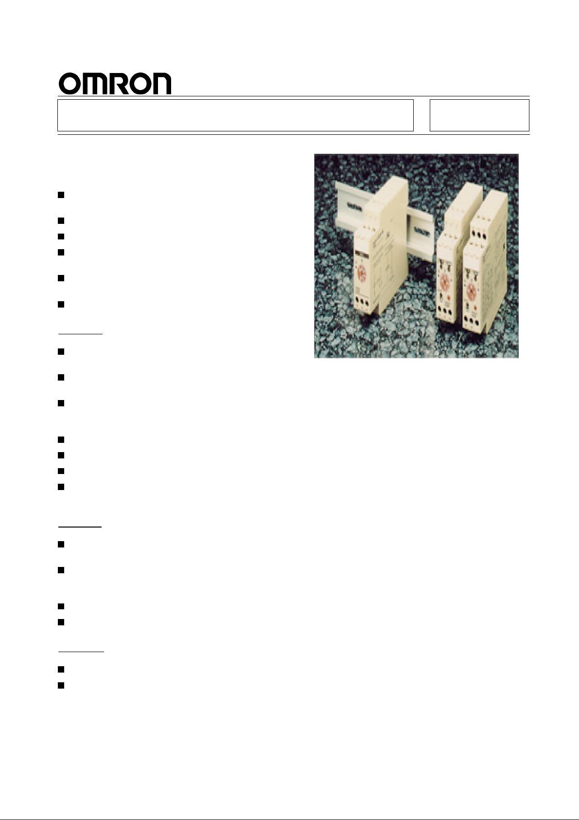
Solid-state Timer
DIN-track Mounted, Standard 22.5-mm
Width Timer Range
Conforms to VDE0435/0110 and approved by UL
and CSA.
Conforms to EMC standards.
NPN and PNP Input Models are available.
Name plates provided for easy timer identification
and management.
Finger-protection terminal block. Delivered with an
open terminal for quick installation.
Six-language insturction manual provided.
H3DR-A Full Multifunction Timer
A wide AC power supply range (100 to 240 VAC)
reduces the number of timer models kept in stock.
Six operating modes cover a wide range of
applications.
Enables easy sequence checks through instantaneous outputs for a zero set value at any time
range.
Start, reset, and gate control inputs provided.
A wide time setting range of 0.10 s to 120 h.
Fine adjustment dial for accurate time settings.
Relay (DPDT) and Transistor Output Models are
available.
H3DR-A/P/M
H3DR-P Multifunction T imer
Six operating modes cover a wide range of
applications.
Enables easy sequence checks through instantaneous outputs for a zero set value at any time
range.
A wide timing range of 0.10 s to 120 h.
Fine adjustment dial for accurate time settings.
H3DR-M Single-function Timer
Economical solution for ON-delay applications.
Sixsingle-timerange types:1s,5 s,10s,30 s,60s,
and 10 min.
1
Page 2
H3DR-A/P/M
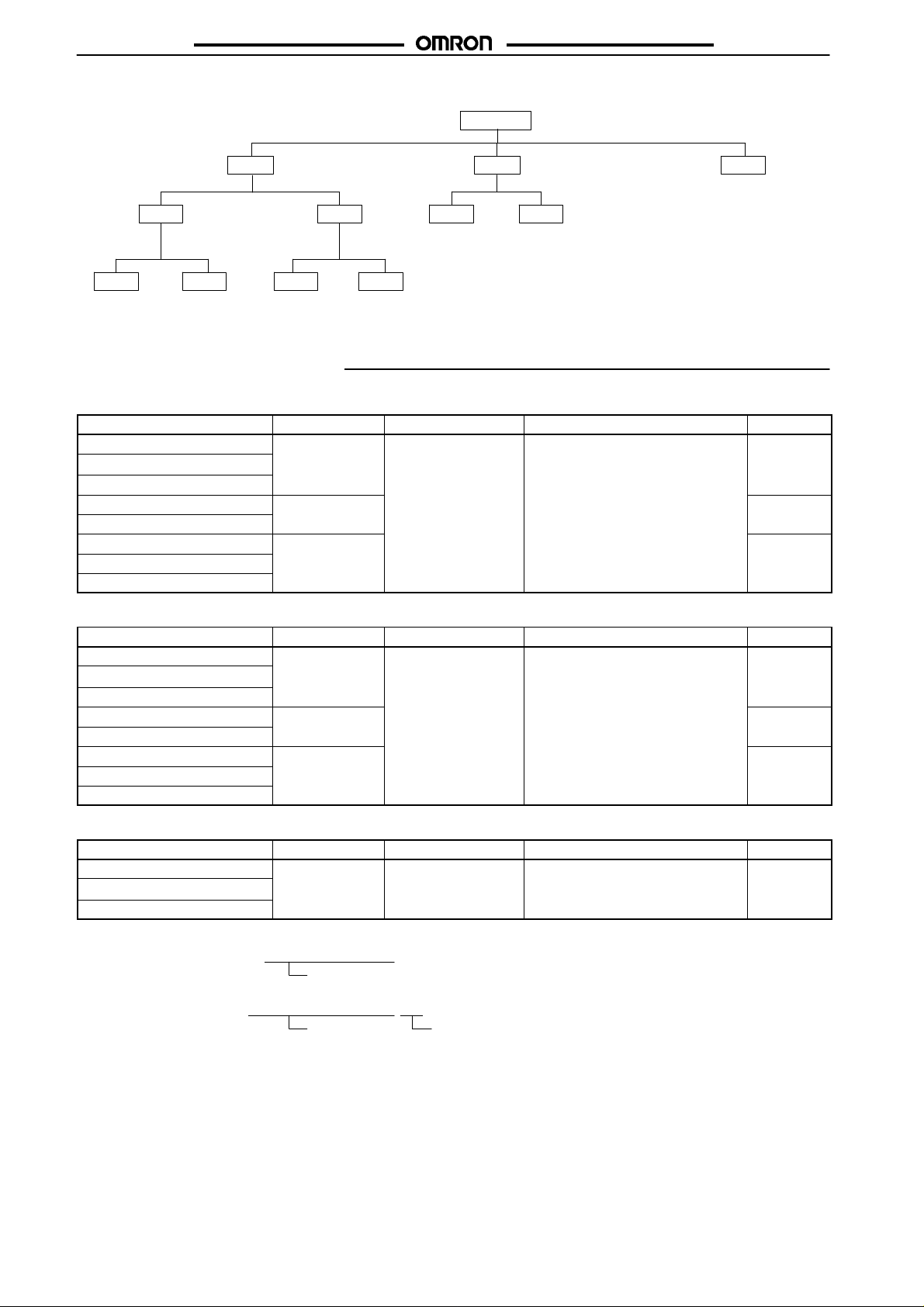
Model Legend of H3DR Series
H3DR-A/P/M
H3DR
-A
Full-multifunction Multifunction Single-function
-A
DPDT Output Transistor
-A -AP
NPN Input PNP Input NPN Input PNP Input
-AS
Output
-AS -ASP
-P -PP
NPN Input PNP Input
-P -M
Ordering Information
NPN (No-voltage) Input Models
Supply voltage Outputs Time range Operating mode Model
100 to 240 VAC (50/60 Hz) Contact (DPDT) 0.10 s to 120 h ON-delay, Flicker OFF start H3DR-A
12 VDC
24 VDC/VAC (50/60 Hz) Signal OFF delay, Interval
12 VDC Transistor (6 multi-mode) H3DR-AS
24 VDC/VAC (50/60 Hz) (Photocoupler)
100 to 120 VAC (50/60 Hz) Contact (SPDT) H3DR-P
200 to 240 VAC (50/60 Hz)
24 VDC/VAC (50/60 Hz)
PNP (Voltage) Input Models
Supply voltage Outputs Time range Operating mode Model
100 to 240 VAC (50/60 Hz) Contact (DPDT) 0.10 s to 120 h ON-delay, Flicker OFF start H3DR-AP
12 VDC
24 VDC/VAC (50/60 Hz) Signal OFF delay, Interval
12 VDC Transistor (6 multi-mode) H3DR-ASP
24 VDC/VAC (50/60 Hz) (Photocoupler)
100 to 120 VAC (50/60 Hz) Contact (SPDT) H3DR-PP
200 to 240 VAC (50/60 Hz)
24 VDC/VAC (50/60 Hz)
(7 multi-range) Flicker ON start, Signal ON/OFF-delay
(7 multi-range) Flicker ON start, Signal ON/OFF-delay
No-input Models
Supply voltage Outputs Time range Operating mode Model
110 to 120 VAC (50/60 Hz) Contact (SPDT) 1 s, 5 s, 10 s, 30 s, ON-delay H3DR-M
220 to 240 VAC (50/60 Hz)
24 VDC/VAC (50/60 Hz) (single-time range)
Note: 1. Specify both the model number and supply voltage when ordering.
Example: H3DR-A/-P 24 VDC/VAC (50/60 Hz)
Supply voltage
2. Specify both the model number, supply voltage, and time range when ordering.
Example: H3DR-M 220 to 240 VAC (50/60 Hz) 30 s
Supply voltage Time range
3. Order H3DR-M Timers in lots of 10 pcs (sold as a single package).
60 s, 10 min
2
Page 3
H3DR-A/P/M
H3DR-A/P/M
Accessories (Order Separately)
Mounting Track 50 cm (l) x 7.3 mm (t) PFP-50N
1 m (l) x 7.3 mm (t) PFP-100N
1 m (l) x 16 mm (t) PFP-100N2
End Plate PFP-M
Spacer PFP-S
Specifications
General
Item H3DR-A/-AS H3DR-AP/-ASP H3DR-P H3DR-PP H3DR-M
Operating mode A: ON-delay
B: Flicker OFF start
B2: Flicker ON start
C: Signal ON/OFF-delay
D: Signal OFF-delay
E: Interval
Terminal block 11/12 terminal 6/12 terminal 5/12 terminal
Input type No-voltage input
(NPN Model)
Output type H3DR-A: Relay output (DPDT);
Voltage input
(PNP Model)
No-voltage input
(NPN Model)
Relay output (SPDT)
Voltage input
(PNP Model)
H3DR-AS: Transistor output
(NPN/PNP) (see note)
Mounting method DIN track mounting
EMC Emission Enclosure: EN55011 Group 1 class A
Emission AC Mains: EN55011 Group 1 class A
Immunity ESD: IEC801-2: 4 kV contact discharge (level 2)
8 kV air discharge (level 3)
Immunity RF-interference: ENV50140: 10 V/m (80 MHz to 1 GHz) (level 3)
Immunity Conducted Disturbance: ENV50141: 10 V (0.15 to 80 MHz) (level 3)
Immunity Burst: IEC801-4: 2 kV power-line (level 3)
2 kV I/O signal-line (level 4)
Approved standards UL508, CSA C22.2 No.14
Conforms to VDE 0435/2021 C/250, C/30 (-AS model), VDE 0110, VDE0106/P100,
IEC947 AC-15 (-Pj and -M models), AC-13 (-Aj model), DC-13 (-ASj model)
Conforms to EN50081-2, prEN50082-2
Note: The internal circuits are optically isolated from the output. This enables application of either NPN or PNP transistors.
ON-delay
---
Time Ranges
H3DR-A j/-AS j/-P j
Time unit s (sec) min h (hrs) x10 h (10 h)
Setting 0 Instantaneous output (see note)
Time scale: x 0.1 0.1 to 1.2 1 to 12
Time scale: x 1 1 to 12 10 to 120
Note: To obtain instantaneous output, set the value below zero.
H3DR-M Single-time Range
Rated time Time range
1 s 0.1 to 1 s
5 s 0.2 to 5 s
10 s 0.5 to 10 s
30 s 1 to 30 s
60 s 2 to 60 s
10 min 0.5 to 10 min
3
Page 4
H3DR-A/P/M
Ratings
NPN (No-voltage) Input Models
Item H3DR-A H3DR-AS H3DR-P
Rated supply
voltage
Operating
voltage range
Power reset Minimum power-opening time: 0.1 s
No-voltage
input
Power
consumption
Control
outputs
Ambient
temperature
Ambient
humidity
Humidity
class
100 to 240 VAC (50/60 Hz),
12 VDC,
24 VDC/VAC (50/60 Hz)
12 VDC,
24 VDC/VAC (50/60 Hz)
100 to 120 VAC (50/60 Hz),
200 to 240 VAC (50/60 Hz),
24 VDC/VAC (50/60 Hz)
85% to 110% of rated supply voltage (90% to 110% with 12-VDC type) 85% to 110% of rated supply voltage
ON impedance: 1 kW max.
ON residual voltage: 1 V max.
OFF impedance: 100 kW min.
100 to 240 VAC: approx. 8 VA
12 VDC: approx. 0.4 W
24 VDC/VAC: approx. 1.3 VA (AC)
100 to 120 VAC: approx. 6 VA
200 to 240 VAC: approx. 10 VA
24 VDC/VAC: approx. 2 VA(AC)
approx. 0.6 W (DC)
Contacts: 5 A at 250 VAC, resistance
load (cosf = 1)
Transistor output: Open collector
(NPN/PNP),
Contacts: 5 A at 250 VAC, resistance
100 mA max. at
30 VDC max.,
residual voltage:
2 V max.
Operating:10°°C to 55°°C (with no icing)
Storage: 25°°C to 65°°C (with no icing)
Operating: 35% to 85%
DIN 40 040: G
H3DR-A/P/M
approx. 1 W (DC)
load (cosf = 1)
PNP (Voltage) Input Models
Item H3DR-AP H3DR-ASP H3DR-PP
Rated supply
voltage
Operating
voltage range
Power reset Minimum power-opening time: 0.1 s
Power
consumption
100 to 240 VAC (50/60 Hz),
12 VDC,
12 VDC,
24 VDC/VAC (50/60 Hz)
24 VDC/VAC (50/60 Hz)
85% to 110% of rated supply voltage (90% to 110% with 12-VDC type)
100 to 240 VAC: approx. 8 VA
12 VDC: approx. 0.4 W
24 VDC/VAC: approx. 1.3 VA (AC)
100 to 120 VAC (50/60 Hz),
200 to 240 VAC (50/60 Hz),
24 VDC/VAC (50/60 Hz)
100 to 120 VAC: approx. 6 VA
200 to 240 VAC: approx. 10 VA
24 VDC/VAC: approx. 2 VA(AC)
approx. 0.6 W (DC)
Control
outputs
Contacts: 5 A at 250 VAC, resistance
load (cosf = 1)
Transistor output: Open collector
(NPN/PNP),
Contacts: 5 A at 250 VAC, resistance
100 mA max. at
30 VDC max.,
residual voltage:
2 V max.
Ambient
temperature
Ambient
humidity
Humidity
class
Operating:10°°C to 55°°C (with no icing)
Storage: 25°°C to 65°°C (with no icing)
Operating: 35% to 85%
DIN 40 040: G
approx. 1 W (DC)
load (cosf = 1)
4
Page 5
H3DR-A/P/M
H3DR-A/P/M
No-input Models
Item H3DR-M
Rated supply
voltage
110 to 120 VAC (50/60 Hz),
220 to 240 VAC (50/60 Hz),
24 VDC/VAC (50/60 Hz)
Operating
voltage range
Power reset Minimum power-opening time: 0.1 s
Power
consumption
85% to 110% of rated supply voltage
110 to 120 VAC: approx. 6 VA
220 to 240 VAC: approx. 10 VA
24 VDC/VAC: approx. 2 VA(AC)
approx. 1 W (DC)
Control
outputs
Ambient
temperature
Ambient
humidity
Humidity
class
Contacts: 5 A at 250 VAC, resistance load (cosf = 1)
Operating:10°°C to 55°°C (with no icing)
Storage: 25°°C to 65°°C (with no icing)
Operating: 35% to 85%
DIN 40 040: G
Characteristics
NPN (No-voltage) Input Models
Item H3DR-A/-AS/-P
Accuracy of operating
time
Setting error ±±10% FS ±±0.05 s max.
Reset time Min. power-opening time: 0.1 s; Min. pulse width: 0.05 s
Reset voltage 10% max. of rated supply voltage
Influence of voltage ±±0.5% FS max. (±±0.5% FS ±±10 ms max. in a range of 1.2 s)
Influence of temperature ±±2% FS max. (±±2% FS ±±10 ms max. in a range of 1.2 s)
Insulation resistance 100 MW min. (at 500 VDC)
Dielectric strength 2,000 VAC (1,000 VAC for -AS model), 50/60 Hz for 1 min (between current-carrying terminal and
Impulse withstand voltage 3 kV (between power terminals) for 100 to 120 VAC, 110 to 120 VAC, 200 to 240 VAC, 220 to 240 VAC,
Noise immunity ±±1.5 kV (between power terminals) (±±400 V for 12 VDC) and ±±600 V (between input terminals),
Static immunity Malfunction: 4 kV
Vibration resistance Destruction: 10 to 55 Hz with 0.75-mm double amplitude each in three directions
Shock resistance Destruction: 980 m/s
Life expectancy Mechanical:20 million operations min. (under no load at 1,800 operations/h)
Enclosure rating IEC: IP40
Weight Approx. 120 g
±±1% FS max. (±±1%±±10 ms in a range of 1.2 s)
+/− +/− +/−
+/− +/− +/−
+/−
+/−
(10 V max. for 100 to 240 VAC, 100 to 120 VAC;
20 V max. for 200 to 240 VAC)
+/− +/− +/−
+/− +/− +/−
+/− +/− +/−
+/− +/− +/−
non-current-carrying metal parts)
2,000 VAC (1,000 VAC for -AS model), 50/60 Hz for 1 min (between control output terminals and
operating circuit)
1,000 VAC, 50/60 Hz for 1 min (between contacts not located next to each other) (except -AS model)
100 to 240 VAC, 1 kV for 12 VDC, 24 VDC/VAC
4.5 kV (between current-carrying terminal and exposed non-current-carrying metal parts) for 100 to
120 VAC, 110 to 120 VAC, 200 to 240 VAC, 220 to 240 VAC, 100 to 240 VAC, 1.5 kV for 12 VDC,
24 VDC/VAC
+/−
+/− +/−
+/− +/−
+/−
square-wave noise by noise simulator (pulse width: 100 ns/1 ms, 1-ns rise)
Destruction: 8 kV
Malfunction:10 to 55 Hz with 0.5-mm double amplitude each in three directions
2
(100G) each in three directions
Malfunction: 98 m/s2(10G) each in three directions
Electrical: 100,000 operations min. (5 A at 250 VAC, resistive load at 1,800 operations/h)
5
Page 6
H3DR-A/P/M
H3DR-A/P/M
PNP (Voltage) Input Models
Item H3DR-AP/-ASP/-PP
+/−
Accuracy of operating
time
Setting error ±±10% FS ±±0.05 s max.
Reset time Min. power-opening time: 0.1 s; Min. pulse width: 0.05 s
Reset voltage 10% max. of rated supply voltage
+/−
±±1% FS max. (±±1%±±10 ms in a range of 1.2 s)
+/− +/−
+/− +/−
+/− +/−
+/− +/−
(10 V max. for 100 to 240 VAC, 100 to 120 VAC;
20 V max. for 200 to 240 VAC)
+/− +/−
Influence of voltage ±±0.5% FS max. (±±0.5% FS ±±10 ms max. in a range of 1.2 s)
Influence of temperature ±±2% FS max. (±±2% FS ±±10 ms max. in a range of 1.2 s)
Insulation resistance 100 MW min. (at 500 VDC)
Dielectric strength 2,000 VAC (1,000 VAC for -ASP model), 50/60 Hz for 1 min (between current-carrying terminal and
+/− +/−
+/− +/− +/−
+/− +/− +/−
+/−
+/−
non-current-carrying metal parts)
2,000 VAC (1,000 VAC for -ASP model), 50/60 Hz for 1 min (between control output terminals and
operating circuit, and contacts of different polarity)
1,000 VAC, 50/60 Hz for 1 min (between contacts not located next to each other)
Impulse withstand voltage 3 kV (between power terminals) for 100 to 120 VAC, 200 to 240 VAC, 100 to 240 VAC,
1 kV for 12 VDC, 24 VDC/VAC
4.5 kV (between current-carrying terminal and exposed non-current-carrying metal parts) for 100 to
120 VAC, 200 to 240 VAC, 100 to 240 VAC, 1.5 kV for 12 VDC, 24 VDC/VAC
+/− +/−
Noise immunity ±±1.5 kV (between power terminals) (±±400 V for 12 VDC) and ±±600 V (between input terminals),
+/−
+/−
+/− +/−
square-wave noise by noise simulator (pulse width: 100 ns/1 ms, 1-ns rise)
Static immunity Malfunction: 4 kV
Destruction: 8 kV
Vibration resistance Destruction: 10 to 55 Hz with 0.75-mm double amplitude each in three directions
Malfunction:10 to 55 Hz with 0.5-mm double amplitude each in three directions
Shock resistance Destruction: 980 m/s
2
(100G) each in three directions
Malfunction: 98 m/s2(10G) each in three directions
Life expectancy Mechanical:20 million operations min.
Electrical: 100,000 operations min. (5 A at 250 VAC, resistive load at 1,800 operations/h)
Enclosure rating IEC: IP40
Weight H3DR-AP: approx. 130 g; H3DR-ASP: approx. 110g; H3DR-PP: approx. 120 g
6
Page 7
H3DR-A/P/M
H3DR-A/P/M
No-input Models
Item H3DR-M
+/−
Accuracy ofoperating
time
Setting error ±±10%FS±±0.05smax.
Resettime Min.power-openingtime:0.1s
Resetvoltage 10%max.ofratedsupplyvoltage
+/−
±±2%FSmax.
+/− +/−
+/− +/−
(10Vmax.for100to240VAC,100to120VAC;
20Vmax.for200to240VAC)
Influence ofvoltage ±±2%FSmax.
Influence oftemperature ±±5%FSmax.
Insulation resistance 100MWmin.(at500VDC)
Dielectric strength 2,000VAC,50/60Hzfor1min(betweencurrent-carryingterminalandnon-current-carryingmetalparts)
+/−
+/−
+/−
+/−
2,000VAC,50/60Hzfor1min(betweencontroloutputterminalsandoperatingcircuit)
1,000VAC,50/60Hzfor1min(betweencontactsnotlocatednexttoeachother)
Impulse withstand voltage 3kV(betweenpowerterminals)for100to120VAC,110to120VAC,200to240VAC,220to240VAC,
100to240VAC,1kVfor12VDC,24VDC/VAC
4.5kV(betweencurrent-carryingterminalandexposednon-current-carryingmetalparts)for100to
120VAC,110to120VAC,200to240VAC,220to240VAC,100to240VAC,1.5kVfor12VDC,
24VDC/VAC
+/− +/−
Noiseimmunity ±±1.5kV(betweenpowerterminals)and±±600V(betweeninputterminals),square-wavenoisebynoise
+/− +/−
simulator(pulsewidth:100ns/1ms,1-nsrise)
Staticimmunity Malfunction:4kV
Destruction:8kV
Vibration resistance Destruction:10to55Hzwith0.75-mmdoubleamplitudeeachinthreedirections
Malfunction:10to55Hzwith0.5-mmdoubleamplitudeeachinthreedirections
Shockresistance Destruction:980m/s
Malfunction:98m/s
Lifeexpectancy Mechanical:20millionoperationsmin.(undernoloadat1,800operations/h)
2
(100G)eachinthreedirections
2
(10G)eachinthreedirections
Electrical: 100,000operationsmin.(5Aat250VAC,resistiveloadat1,800operations/h)
Enclosure rating IEC:IP40
Weight Approx.120g
Note: TheresetvoltageistheresidualvoltageallowedfromthepowersupplywhenreturningtheTimertothestatusthatexistedpriorto
operation.
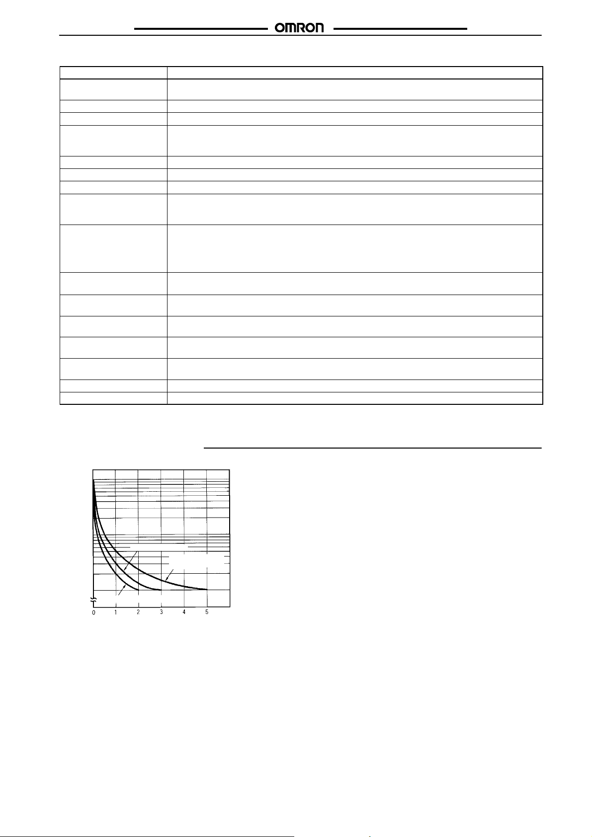
EngineeringData
10,000
3
5,000
1,000
3
30 VDC L/R = 7ms
500
Switching operations(x 10 )
100
30 VDC L/R = 7ms
2
250 VAC (cos = 0.4)
250 VAC (cos = 0.4)
Loadcurrent(A)
250VAC/30VDC
(cosf=1)
Reference:Amaximumcurrentof0.15Acanbeswitchedat125VDC(cosf=1).
Maximumcurrentof0.1AcanbeswitchedifL/Ris7ms.Inbothcases,
alifeof100,000operationscanbeexpected.
Theminimumapplicableloadis10mAat5VDC(failurelevel:P).
7
Page 8
H3DR-A/P/M
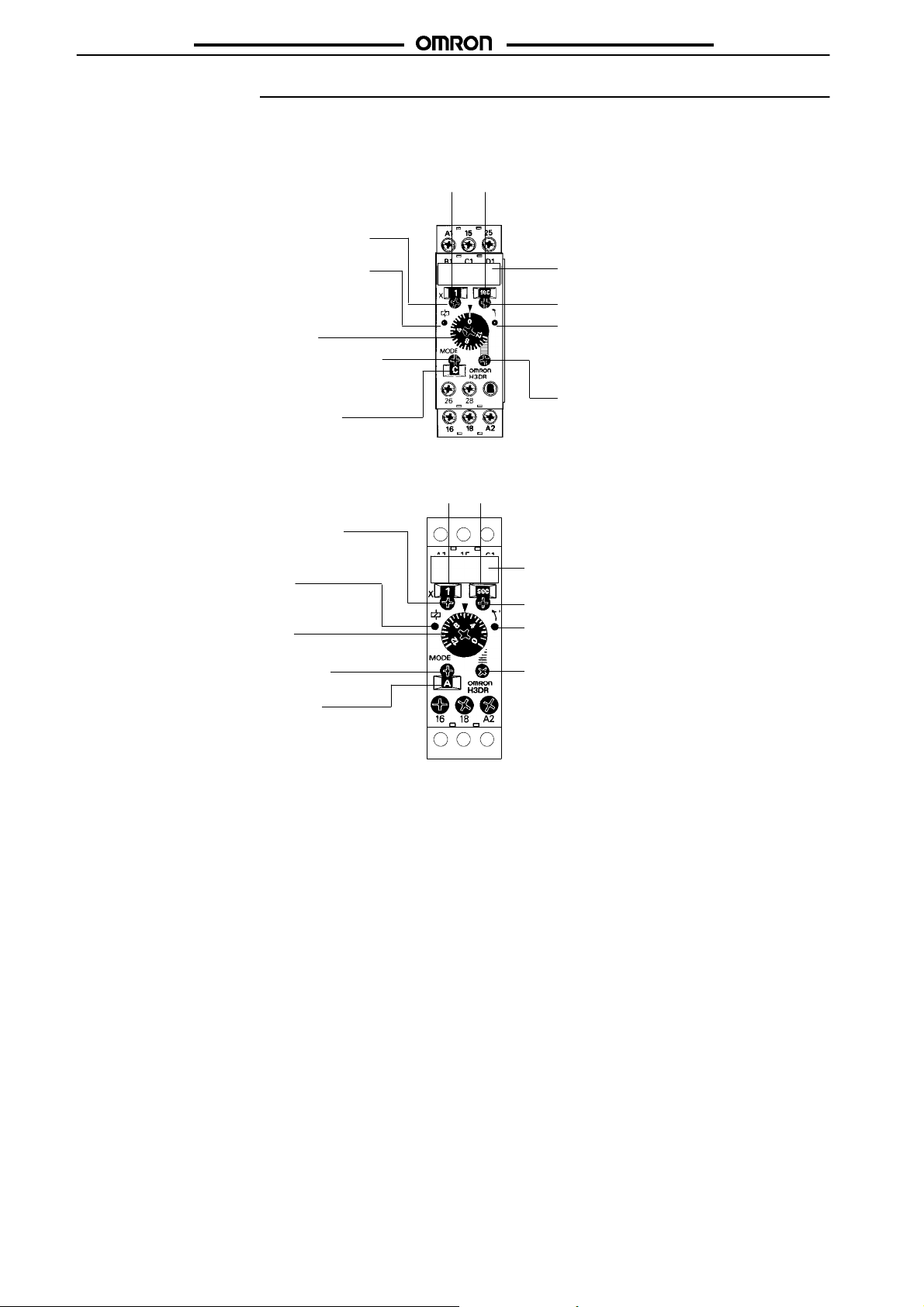
Nomenclature
NPN Input Models
H3DR-A/-AS
Scale range selector (select 0.1 or 1)
Scale range
display window
H3DR-A/P/M
Time unit display
window
Power indicator (green) (Flashes when
Timer operates; lit when Timer stops
operating)
Time setting dial (set time)
Operating mode selector (select a mode
from A, B, B2, C, D, and E)
Operating mode display window
H3DR-P
Scale range selector (select 0.1 or 1)
Power indicator (green)
Time setting dial (set time)
Operating mode selector (select a
mode from A, B, B2, C, D, and E)
Operating mode display window
Scale range
display window
Name plate for user use (20 x 6.6 mm)
Time unit selector (select one
from sec, min, hrs, and 10 h)
Output indicator (orange)
Fine-tuning dial (use to
fine-tune the set time)
Time unit display
window
Name plate for user use (20 x 8 mm)
Time unit selector (select one
from sec, min, hrs, and 10 h)
Output indicator (orange)
Fine-tuning dial (use to finetune the set time)
8
Page 9

H3DR-A/P/M
PNP Input Models
H3DR-AP/-ASP
Scale range selector (select 0.1 or 1)
Scale range
display window
H3DR-A/P/M
Time unit display
window
Power indicator (green) (Flashes when
Timer operates; lit when Timer stops
operating)
Time setting dial (set time)
Operating mode selector (select a mode
from A, B, B2, C, D, and E)
Operating mode display window
H3DR-PP
Scale range selector (select 0.1 or 1)
Power indicator (green)
Time setting dial (set time)
Operating mode selector (select a
mode from A, B, B2, C, D, and E)
Operating mode display window
Scale range
display window
A1 15 B1
Name plate for user use (20 x 6.6 mm)
Time unit selector (select one
from sec, min, hrs, and 10 h)
Output indicator (orange)
Fine-tuning dial (use to
fine-tune the set time)
Time unit display
window
Name plate for user use (20 x 6.6 mm)
Time unit selector (select one
from sec, min, hrs, and 10 h)
Output indicator (orange)
Fine-tuning dial (use to finetune the set time)
No-input Models
H3DR-M
Power indicator (green)
Time setting dial (set time)
Name plate for user use
(20 x 6.6 mm)
9
Page 10

H3DR-A/P/M
Operation
Block Diagram
H3DR-A/P/M
H3DR-A/-AS/-AP/-ASP
H3DR-P/-PP
AC (DC) input
Power supply
circuit
Reset input, start input, and gate input
AC (DC) input
Power supply
circuit
Zero setting
detection
circuit
Oscillation
circuit
Zero setting
detection
circuit
Oscillation
circuit
Time range/
unit selectors
Counting
circuit
Input circuit
Time range/
unit selectors
Counting
circuit
Operating
mode selector
Output circuit
Indicator
circuit
Power-ON
indicator
Operating
mode selector
Output circuit
Output-ON
indicator
H3DR-M
AC (DC) input
Power supply
circuit
Start input
Oscillation
circuit
Input circuit
Counting
circuit
Indicator
circuit
Power-ON
indicator
Output circuit
Indicator
circuit
Power-ON
indicator
Output-ON
indicator
10
Page 11

H3DR-A/P/M
H3DR-A/P/M
I/O Functions
H3DR-A/-AS/-AP/-ASP
Inputs Start Starts time-measurement.
Reset Interrupts time-measurement and resets preset time-measurement value. No time-measurement is
made and control output is OFF while the reset input is ON.
Gate Prohibits time-measurement.
Output Control output Outputs are turned ON according to designated output mode when preset value is reached.
H3DR-P/-PP
Input Start Starts time-measurement.
Output Control output Output is turned ON according to designated output mode when preset value is reached.
H3DR-M
Input No input is available.
Output Control output Output is turned ON when preset value is reached.
Basic Operation
H3DR-A j/-AS j/-P j
Setting of Selector
The selectors can be turned clockwise and counterclockwise to select the desired time unit, time scale, or operating mode.
Each selector has a snap mechanism that secures the selector at a
given position. Set the selector at a position at which it is secured.
Do not set it midway between two securing positions or a malfunction could result from improper setting.
Selection of Time Unit and Time Scale
The desired time unit (s, m, h, or 10h) can be displayed in the window above the time setting dial by turning the time unit selector located at the upper right corner of the front panel. Time scale (0.1 or
1) is selected with the time scale selector at the upper left corner of
the front panel, it appears in the window above the selector.
Groove for
screwdriver
A
Operating
mode display
window
Operating
mode selector
Selection of Operating Mode
Turn the operating mode selector with a screwdriver until the desired operating mode (A, B, B2, C, D, or E) appears in the display
window located below the selector.
Time unit display
window
Scale range
Scale range
Scale range
display window
display window
display window
Scale range
selector
Time unit selector
Setting of Time
The desired time is set with the time setting dial. This time can be
fine-tuned by adjusting the fine-tuning dial (the reduction ratio of the
fine-tuning dial is 1:6). The fine-tuning dial is useful when delicate
and more accurate adjustment is required.
Time setting
dial
H3DR-M
The H3DR-Mdoes not incorporate ascale range selector,operating
mode selector, or fine-tuning.
Fine-tuning dial
11
Page 12

H3DR-A/P/M
H3DR-A/P/M
Timing Chart
Note: 1. The minimum power-opening time is 0.1 s and the minimum pulse width is 0.05 s.
2. The letter t in the timing charts stands for the set time and t-a means that the period is less than the time set.
NPN/PNP Input Models
H3DR-A/-AS/-AP/-ASP
Operating mode Timing chart
A: ON-delay For power-on operation, short-circuit the start input and input common terminal.
B:
Flicker OFF start
B2:
Flicker ON start
C:
Signal
ON/OFF-delay
Note: For NPN Input Models, “Start” stands for short-circuited C
For PNPInput Models, “Start” standsfor voltage application betweenB1and A2, and“Reset” standsfor voltage applicationbetween C
and A2.
The timer starts operating at the moment the power is turned on.
t t
t
t
Power
Start
(see note)
Reset
(see note)
Output relay
(NC)
Output relay
(NO) (Output
indicator)
Power
indicator
Basic operation
Power
Start
Output
For power-on operation, short-circuit the start input and input common terminal.
The timer starts operating at the moment the power is turned on.
t a
Power
Start (see note)
Reset (see note)
Output relay
(NC)
Output relay
(NO) (Output
indicator)
Power indicator
t
t tt
t
Basic operation
Power
Start
Output
For power-on operation, short-circuit the start input and input common terminal.
The timer starts operating at the moment the power is turned on.
t a
Power
Start (see note)
Reset (see note)
Output relay
(NC)
Output relay
(NO) (Output
indicator)
Power indicator
Power
Start
(see note)
Reset (see note)
Output relay
(NC)
Output relay
(NO) (Output
indicator)
Power
indicator
t t
tt t t
t - a
t
and A2, and “Reset” stands for short-circuited D1and A2.
1
t
Basic operation
Power
Start
Output
t - a t - a
t
Basic operation
Power
Start
Output
t
t
t
t t t t
t t
t t
t t t t
t
t
tt
t
t
t
t
1
12
Page 13

H3DR-A/P/M
Operating mode Timing chart
D:
Signal OFF-delay
Power
Start
(see note)
Reset
(see note)
Output relay
(NC)
Output relay
(NO) (Output
indicator)
Power
indicator
t
t a
t a
H3DR-A/P/M
t
t a
Power
Start
Output
t
ttt
E: Interval
Basic operation
For power-on operation, short-circuit the start input and input common terminal.
The timer starts operating at the moment the power is turned on.
t t t
Power
Start
(see note)
Reset
(see note)
Output relay
(NC)
Output relay
(NO) (Output
indicator)
Power
indicator
Basic operation
Note: For NPN Input Models, “Start” stands for short-circuited C
For PNPInput Models, “Start” standsfor voltage application betweenB1and A2, and“Reset” standsfor voltage applicationbetween C
Power
Start
Output
and A2, and “Reset” stands for short-circuited D1and A2.
1
t - a t - a
t
t
t
and A2.
1
13
Page 14

H3DR-A/P/M
Operating mode Timing chart
G:
Signal
ON/OFF-delay
J:
One-shot output
t t t t
Power
Start
(see note)
Reset
(see note)
Output relay
(NC)
Output relay
(NO) (Output
indicator)
Power
indicator
For power-on operation, short-circuit the start input and input common terminal.
The timer starts operating at the moment the power is turned on.
Power
Start
(see note)
Reset
(see note)
Output relay
(NC)
Output relay
(NO) (Output
indicator)
Power
indicator
t
Is Is
Basic operation
t - a t - a
t - a
Power
t - a
H3DR-A/P/M
Basic operation
Power
Start
Output
t
t
tt
tt2t
t
Start
Output
Note: 1. For NPN Input Models, “Start” stands for short-circuited C
For PNPInput Models, “Start” standsfor voltage application betweenB1and A2, and“Reset” stands forvoltage applicationbetween
t
and A2, and “Reset” stands for short-circuited D1and A2.
1
1±±0.6 s
C1and A2.
2. The G and J modes are special modes. Order the H3DR-Aj-300 special model for these modes.
Gate Signal Input
t
ON
Power
OFF
ON
Start
OFF
Gate
ON
(see
OFF
note)
ON
Reset
OFF
ON
Output
relay
OFF
Note: 1. This timing chart indicates the gate input in operating mode A (ON-delay operation).
1
t
2
t2
2. The set time is the sum of t1and t2.
3. For NPN Input Models, “Gate” stands for short-circuited D1and A2.
For PNP Input Models, “Gate” stands for voltage application between D1and A2.
14
Page 15

H3DR-A/P/M
For
power-on
operation,
short-circuit
the
start
input
and
input
common
terminal.
H3DR-P/-PP
Operating
mode
A: ON-delay
B:
Flicker OFF
start
Timing chart
The timer starts operating at the moment the power is turned on.
Power (A1and A2)
Start (see note)
Output relay
(NC, 15 and 16)
Output relay
(NO, 15 to 18)
(output indicator)
Power indicator
t t
ta
For power-on operation, short-circuit the start input and input common terminal.
The timer starts operating at the moment the power is turned on.
t t ta t t t ta
Basic operation
Power
Start
Output
H3DR-A/P/M
t
t
t
Power (A1and A2)
Start (see note)
Output relay
(NC, 15 and 16)
Output relay
(NO, 15 to 18)
(output indicator)
Power indicator
B2:
Flicker ON
start
Note: For NPN Input Models, “Start” stands for short-circuited C
For power-on operation, short-circuit the start input and input common terminal.
The timer starts operating at the moment the power is turned on.
t tt ta t t ta
Power (A1and A2)
Start (see note)
Output relay
(NC, 15 and 16)
Output relay
(NO, 15 to 18)
(output indicator)
Power indicator
and A2.
For PNP Input Models, “Start” stands for voltage application between B1and A2.
1
Basic operation
Power
Start
Output
Basic operation
Power
Start
Output
t t
t t
t t
t
t t
t t
t t
t t
t
15
Page 16

H3DR-A/P/M
H3DR-A/P/M
Operating
mode
C:
Signal
ON/OFFdelay
D:
Signal
OFF-delay
Power (A1and A2)
Start (see note)
Output relay
(NC, 15 and 16)
Output relay
(NO, 15 to 18)
(output indicator)
Power indicator
Power (A1and A2)
Start (see note)
Output relay
(NC, 15 and 16)
Output relay
(NO, 15 to 18)
(output indicator)
Timing chart
t t ta ta
t t
tt ta ta t ta
Basic operation
Power
Start
Output
Basic operation
Power
Start
Output
tt
t
t
ttt
t
Power indicator
E: Interval
For power-on operation, short-circuit the start input and input common terminal.
The timer starts operating at the moment the power is turned on.
t t
Power (A1and A2)
Start (see note)
Output relay
(NC, 15 and 16)
Output relay
(NO, 15 to 18)
(output indicator)
Power indicator
Note: For NPN Input Models, “Start” stands for short-circuited C
For PNP Input Models, “Start” stands for voltage application between B1and A2.
t
ta
and A2.
1
No-input Model
H3DR-M
Operating
mode
ON-delay
Power
(A1and A2)
Output relay
(NC, 15 and 16)
Output relay
(NO, 15 to 18)
Power indicator
tat t
ta
Timing chart
Basic operation
Power
Start
Output
Basic operation
Power
Output
t
t
t
16
Page 17

H3DR-A/P/M
Dimensions
Note: All units are in millimeters unless otherwise indicated.
H3DR-P/-PP H3DR-MH3DR-A/-AS/-AP/-ASP
Accessories (Order Separately)
Mounting Track
PFP-100N, PFP-50N
PFP-100N2
22.5
Wiring terminal (M3 fork or single wire is connectable)
54
75
54
54
76.5
23.5
23.5
23.5
76.5
76.5
(100)
H3DR-A/P/M
4.5
15 25 25 25 25
10 10
L
L: Length
1 m PFP-100N
50 cm PFP-50N
1 m PFP-100N2
End Plate
PFP-M
27
16
24
1 1.5
29.2
*
7.3±±0.15
35±±0.3
27±±0.15
1
4.5
15 25 25 25 25 15
10 10
L
35±±0.3
Spacer
PFP-S
10
6.2
1.8
1
1.3
4.8
35.5 35.3
1.8
50
11.5
10
M4 x 8 pan
head
screw
5
44.3
16
12
16.5
34.8
34.8
34.8
17
Page 18

H3DR-A/P/M
Installation
Terminal Arrangement
NPN Input Models
H3DR-A/P/M
H3DR-A
DPDT Relay Output
H3DR-P
15
C
1
A
1
15
H3DR-AS
Transistor Output
Reset
Start
Reset
Start
Gate
B
C
A
+
1
Power
supply
A
2
D
1
1
1
Note: The H3DR-A/-P incorporates multiple operating
A
1
+
Power
supply
A
2
Gate
B
C
D
1
1
1
modes (6 modes), thus uses a new timer contact
symbols which are different from conventional ones
used for other digital timers.
A
1
+
Power
supply
Start
C
1
16 18
16 18
A
A
2
2
18
Page 19

H3DR-A/P/M
PNP Input Models
H3DR-A/P/M
H3DR-AP
DPDT Relay Output
H3DR-PP
15
B
1
A
1
15
H3DR-ASP
Transistor Output
A
1
+
Power
supply
Reset
Start
A
2
Gate
C
B
D
1
1
1
Note: The H3DR-AP/-PP incorporates multiple operating
A
1
+
Power
supply
Reset
Start
A
2
Gate
C
B
D
1
1
1
modes (6 modes), thus uses a new timer contact
symbols whicharedifferentfrom conventional ones
used for other digital timers.
A
1
+
Power
supply
16 18
16 18
A
2
No-input Models
H3DR-M
A
15
1
15
16 18
16 18
A
2
Start
A
2
B
1
A
1
+
Power
supply
A
2
19
Page 20

H3DR-A/P/M
Input Connections (H3DR-A/-P/-AP/-PP)
NPN Input Models
The inputs of the H3DR-A/-AS/-P are no-voltage (short circuit or open) inputs.
H3DR-A/-AS
No-voltage inputs
No-contact Input
(Connection to NPN open
collector output sensor.)
12 to 24 VDC (sensor
power supply)
+DC power
supply
Contact Input
No-contact Input
(Connection to a voltage
output sensor.)
12 to 24 VDC (sensor
power supply)
+DC power
H3DR-A/P/M
supply
Timer
Sensor
Start/reset/
gate
Input (0 V):
A
2
Operates with transistor ON
H3DR-P
No-voltage inputs
No-contact Input
(Connection to NPN open
collector output sensor.)
12 to 24 VDC (sensor
power supply)
+DC power
supply
Timer
Sensor
Start
Input (0 V):
A
2
Operates with transistor ON
No-voltage Input Signal Levels
1. Short-circuit level
Transistor ON
No-contact
input
Residual voltage: 1 V max.
Impedance when ON: 1 kW max.
2. Open level
Transistor OFF
Impedance when OFF: 100 kW min.
Contact
input
Use contacts which can
adequately switch 0.1 mA at 5 V
Operates with relay ON
Contact Input
Operates with relay ON
Timer
Start/reset/
gate
Input (0 V):
A
2
Timer
Start
Input (0 V):
A
2
Sensor
Operates with transistor ON
No-contact Input
(Connection to a voltage
output sensor.)
12 to 24 VDC (sensor
power supply)
Sensor
Operates with transistor ON
Timer
Start/reset/
gate
Input (0 V):
A
2
+DC power
supply
Timer
Start
Input (0 V):
A
2
20
Page 21

H3DR-A/P/M
PNP Input Models
The inputs of the H3DR-AP/ASP/-PP are voltage (voltage imposition or open) inputs.
H3DR-AP/-ASP
Voltage Inputs
No-contact Input
(Connection to PNP output sensor.)
12 to 24 VDC (sensor
power supply)
Sensor
Operates with transistor ON
+DC power
supply
Timer
A
1
Start/reset/
gate
A2(0 V)
H3DR-PP
Voltage inputs
No-contact Input (for 24 VDC/V AC Model)
(Connection to PNP output sensor.)
Sensor
Contact Input
Timer
Operates with relay ON
Contact Input
A
1
Start/reset/
gate
Voltage Input Signal Levels
1. Voltage imposition
Transistor ON
No-contact
input
Residual voltage: 1 V max.
Impedance when ON: 1 kW max.
2. Open level
Transistor OFF
Impedance when OFF: 100 kW min.
Contact
input
Use contacts which can
adequately switch 0.1 mA at 5 V
H3DR-A/P/M
B
24 VDC
Operates with transistor ON Operates with relay ON
Voltage Input Signal Levels
Start
A
1
1
A
2
1. Transistor ON
Residual voltage: 1 V max.
No-contact
input
(Voltage between terminals B1and A2must be more than
the operating voltage range.)
2. Transistor OFF
Leakage current: 0.01 mA max.
(Voltage between terminals B1and A2must be less than
the operating voltage range.)
Use contacts that can adequately switch 0.1 mA at each
Contact
input
voltage to be imposed. (When the contacts are ON or
OFF, voltage between terminals B1and A2must be more
than the operating voltage range or less than the
operating voltage range respectively.)
B
1
Start
TimerTimer
A
1
A
2
21
Page 22

H3DR-A/P/M
Precautions
H3DR-A/P/M
Changing of Setting
NOTICE: Do not change the time unit, rated time, or operating
mode while the timer isin operation or malfunction could
result.
Mounting and Dismounting
The H3DR should be mounted as horizontally as possible.
When mounting the H3DRon a socket mounting track, hook portion
(A) of the Timer to an edge of the track first, and then depress the
Timer in the direction of (B).
(A)
(B)
When dismounting the H3DR, pull out portion (C) with a flat-blade
screwdriver and remove the Timer from the mounting track.
Power Supplies
An AC power supply can be connected to the power input terminals
without regardingpolarity. ADC power supply mustbe connected to
the power input terminals as designated according to the polarity of
the terminals.
A DC power supply can be connected if its ripple factor is 20% or
less and the mean voltage is within the rated operating voltage
range of the Timer .
Connect the power supply voltage through a relay or switch in such
a way that the voltage reaches a fixed value at once or the Timer
may not be reset or a timer error could result.
For the power supply of an input device, use an isolating transformer, of which the primary and secondary windings are mutually isolated and the secondary winding is not grounded.
NPN Input Models
H3DR-A/-AS/-P
Input
Input
Circuit
PNP Input Models
Input
terminal
terminal
terminal
Rectifier circuit
H3DR-AP/-ASP/-PP
Isolation transformer is required.
Power supply
(C)
30 mm min.
Rail stopper
The H3DR can be mounted and dismounted with ease if a distance
of 30 mm or more is kept between the H3DR and other equipment.
Input
Circuit
Input
Input
terminal
terminal
terminal
Rectifier circuit
Isolation transformer is required.
Power supply
For the H3DR-P/M, use a commercial power supply with a sinewave frequency of 50 or 60 Hz to supply 100 or 200 VAC.
If a different power supply is to be used, use the H3DR-Ajj.
The powersupply circuit of a H3CR-Aj 100-to-240-VACmodel is a
switching circuit.If the power lineconnected to the powersupply circuit has a transformer with high inductance, a counter-electromotive voltage will be induced by the inductance. To suppress the voltage, apply a CR filter to the power supply line.
Wiring
NPN Input Models
Incorrect
Power supply
AC or DC
Input terminal
B1, D1, C
1
R, G, S
A
1
H3DR-A/-AS
/-P
A
2
22
Securely connect the power supply to terminals A1and A2.
Do not apply input signals unless A2is connected tothe power supply, otherwise the internal circuit of the Timer may be damaged due
to the high-tension voltage applied to the input terminals.
Page 23

H3DR-A/P/M
Input/Output
NPN Input Models
H3DR-A/-AS
H3DR-A/P/M
PNP Input Models
H3DR-AP/-ASP
Power supply
AC or DC
**
D1, C1, B
G, S, R
Input contact
1
Input terminal
L
A
1
H3DR-A/-AS
A
2
*
An appropriate input is applied to the input signal terminals of the
Timer when one of the input terminals (terminals B1, C1, or D1) and
the commonterminal (terminal A2) forthe input signals are short-circuited. Do not attempt to connect any input terminal to any terminal
other than the common terminal or to apply voltage across other
than the specified input and common terminals or the internal circuits of the Timer may be damaged.
* Power supply terminal A2is a common terminal for the input sig-
nals (G,S, R) tothe Timer.Neveruseterminal A1as thecommon
terminal forthis purpose, otherwise the internal circuitof the Timer may be damaged.
** Do not connect a relay or any other load between these two
points, otherwise the internal circuit of the Timer may be damaged due to the high-tension voltage applied to the input terminals.
H3DR-P
Power supply
AC or DC
Input terminal
L
**
C
1
S
Input contact
H3DR-P
A
A2*
1
Power supply
AC or DC
L
Input terminal
B1, C1, D
S, R, G
1
A
H3DR-AP/
H3DR-ASP
A
1
2
Do not connect a relay or any other load between these two points,
otherwise the internal circuit of the Timer may be damaged due to
the high-tension voltage applied to the input terminals.
All Models
Contact or transistor for
external input signal
Incorrect
Correct
Short-circuit
current
H3DR series timer
Input
terminal
Input
Input
Input
terminal
terminal
terminal
Input
Input
Input
terminal
terminal
terminal
Input
Input
Input
terminal
terminal
terminal
Power supply
Power supply
An appropriate input is applied to the input signal terminals of the
Timer when the input terminal (terminal C1) and the common terminal (terminal A2) for the input signal are short-circuited. Do not attempt to connect any input terminal to any terminal other than the
common terminalor to apply voltage across other than thespecified
input and commonterminals or the internal circuits of the Timermay
be damaged.
* Power supply terminal A2is a common terminal for the input sig-
nals (S) to the Timer. Never use terminal A1as the common terminal for this purpose, otherwise the internal circuit of the Timer
may be damaged.
** Do not connect a relay or any other load between these two
points, otherwise the internal circuit of the Timer may be damaged due to the high-tension voltage applied to the input terminals.
When connecting a relay or a transistor as an external signal input
device, pay attention to the following points to prevent short-circuiting due to a sneak current to the transformerless power supply.
If a relay or transistor is connected to two or more Timers, the input
terminals ofthose Timers mustbe wired properlyso thatthey will not
be different in phase or the terminals will be short-circuited to one
another (refer to the figures below).
23
Page 24

H3DR-A/P/M
H3DR-A/P/M
Output Connection of H3DR-AS with
Transistor Output
The H3DR-AS transistor output is insulated fromthe internal circuitry by a photocoupler, so either NPN or PNP output is possible.
Application as NPN Output
DC+
Load
A
1
H3DR
Power supply
for H3DR
Application as PNP Output
Power supply
for H3DR
Input
terminal
Input
contact
Input
terminal
Input
Input
Input
contact
contact
contact
H3DR
9
Power supply
for Load
11
A
2
DC-
DC+
A
1
9
Power supply
for Load
11
A
2
Load
DC-
Environment
When usingthe Timer inan area with excesselectronic noise,separate the Timer ,wiring, and the equipment which generates the input
signals as far as possible from the noise sources. It is also recommended to shield the input signal wiring to prevent electronic interference.
Organic solvents (such as paint thinner), as well as very acidic or
basic solutions can damage the outer casing of the Timer .
Others
If the Timer is mounted on a control board, dismount the timer from
the control board or short-circuit the circuitry of the power board before carrying out a voltage withstand test between the electric circuitry and non current-carrying metal part of the Timer , in order to
prevent the internal circuitry of the Timer from damage.
ALL DIMENSIONS SHOWN ARE IN MILLIMETERS.
To convert millimeters into inches, multiply by 0.03937. To convert grams into ounces, multiply by 0.03527.
Cat. No. L83-E1-3A In the interest of product improvement, specifications are subject to change without notice.
OMRON Corporation
Systems Components Division
28th Fl., Crystal Tower Bldg.
1-2-27, Shiromi, Chuo-ku,
Osaka 540 Japan
Phone: 06-949-6012 Fax: 06-949-6021
24
Printed in Japan
0697-0.5C (0696)
 Loading...