

Page 1
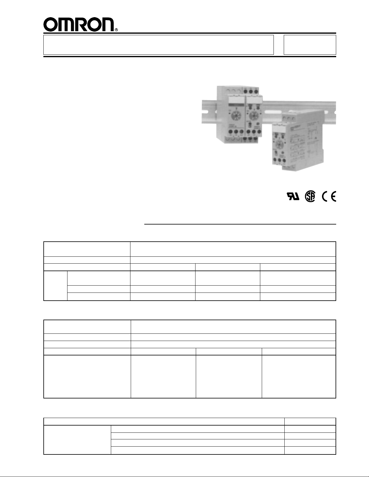
Solid-State Timer H3DR
Analog Set Multifunction Timers in
Slim Design for Track Mounting
■ All settings are made though front panel
■ Six operating modes in a single timer
provides flexibility for many applications
■ Economical ON-delay only models
available in six, single-time ranges
■ Wide timing range of 0.12 seconds to
120 hours
■ Fine adjustment dial for precise
time setting
■ Name plates provide for easy timer
identification and management
■ Terminal block accepts both fork or
bar-sleeve connectors
Ordering Information
■ MULTIFUNCTION TIMERS
Timing functions ON-delay, Repeat cycle/signal OFF start, Repeat cycle/signal ON start,
Signal ON/OFF-delay, Signal OFF-delay, and Interval
Terminal form Screw terminals
Outputs DPDT contact SPDT contact NPN/PNP transistor
Part AC supply voltage H3DR-A-AC100-240 H3DR-P-AC100-120 —
number (50/60 Hz) H3DR-P-AC200-240
AC/DC supply voltage H3DR-A-AC/DC24 H3DR-P-AC/DC24 H3DR-AS-AC/DC24
DC supply voltage H3DR-A-DC12 — H3DR-AS-DC12
■ ON-DELAY ONLY TIMERS
Timing ranges 1S = 0.1 to 1 second; 5S = 0.2 to 5 seconds; 10S = 0.5 to 10 seconds;
30S = 1 to 30 seconds; 60S = 2 to 60 seconds; 10M = 0.5 to 10 minutes
Terminal form Screw terminals
Output SPDT contact
Supply voltage 110 to 120 VAC, 50/60 Hz 220 to 240 VAC, 50/60 Hz 24 VAC/VDC
Part number H3DR-M-AC110-120-1S H3DR-M-AC220-240-1S H3DR-M-AC/DC24-1S
H3DR-M-AC110-120-5S H3DR-M-AC220-240-5S H3DR-M-AC/DC24-5S
H3DR-M-AC110-120-10S H3DR-M-AC220-240-10S H3DR-M-AC/DC24-10S
H3DR-M-AC110-120-30S H3DR-M-AC220-240-30S H3DR-M-AC/DC24-30S
H3DR-M-AC110-120-60S H3DR-M-AC220-240-60S H3DR-M-AC/DC24-60S
H3DR-M-AC110-120-10M H3DR-M-AC220-240-10M H3DR-M-AC/DC24-10M
■ ACCESSORIES
Description Part number
Mounting track DIN rail, 50 cm (1.64 ft) length PFP-50N
DIN rail, 1 m (3.28 ft) length PFP-100N
End plate PFP-M
Spacer PFP-S
1
Page 2
H3DR H3DR
■ RANGE SELECTION
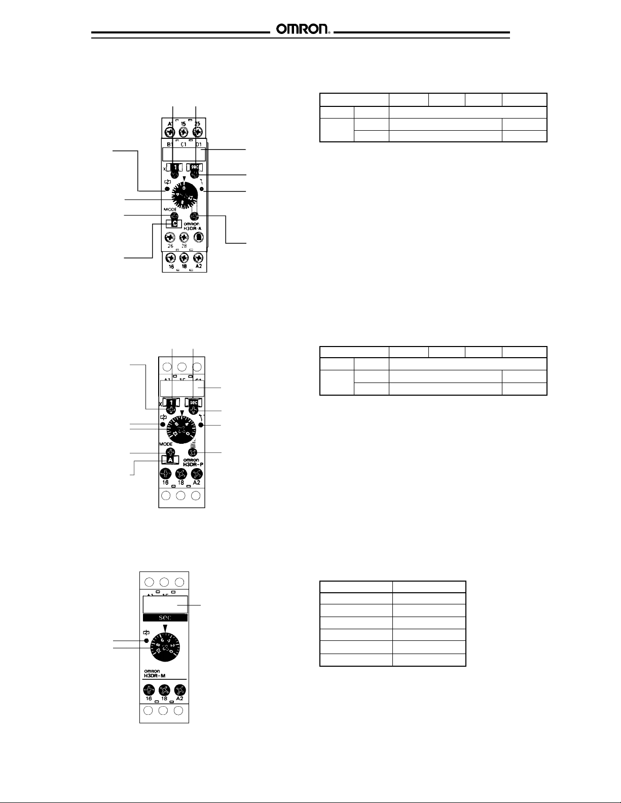
H3DR-A, H3DR-AS
Power ON indicator
Time setting knob
Operation
mode selector
Mode display
A: ON-delay
B: Repeat cycle, signal OFF start
B2: Repeat cycle, signal ON start
C: Signal ON/OFF-delay
D: Signal OFF-delay
E: Interval
Scale range
display
Time unit
display
Identification panel
for user notation
Time unit selector:
sec, min, hr, 10h
Output indicator
Fine-tuning
adjustment
Timing unit Seconds Minutes Hours 10 hours
Setting 0 Instantaneous output
Time x 0.1 0.12 to 1.2 1.2 to 12
scale x 1 1.2 to 12 12 to 120
H3DR-P
Scale range
selector
Power ON indicator
Time setting knob
Operation
mode selector
Mode display
A: ON-delay
B: Repeat cycle, signal OFF start
B2: Repeat cycle, signal ON start
C: Signal ON/OFF-delay
D: Signal OFF-delay
E: Interval
H3DR-M
Power ON indicator
Time setting knob
Scale range
display
Time unit
display
Identification panel
for user notation
Time unit selector:
sec, min, hr, 10h
Output indicator
Fine-tuning
adjustment
Identification panel
for user notation
Timing unit Seconds Minutes Hours 10 hours
Setting 0 Instantaneous output
Time x 0.1 0.12 to 1.2 1.2 to 12
scale x 1 1.2 to 12 12 to 120
Rated time Time range
1 s 0.1 to 1 second
5 s 0.2 to 5 seconds
10 s 0.5 to 10 seconds
30 s 1 to 30 seconds
60 s 2 to 60 seconds
10 min 0.5 to 10 minutes
2
Page 3
H3DR
Specifications
Part number H3DR-A H3DR-AS H3DR-P H3DR-M
Supply voltage AC 24 V or 100-240, 50/60 Hz 24 V, 100-120 V or 24 V, 110-120 V or
200-240 V, 50/60 Hz 220-240 VAC, 50/60 Hz
DC 12 V or 24 V 24 V 24 V
Operating voltage 85% to 110% of rated voltage (90% to 110% with 12 VDC type)
Power AC 10 VA 6 VA, 100-120 VAC 6 VA, 110-120 VAC
consumption 10 VA, 200-240 VAC 10 VA, 220-240 VAC
2 VA, 24 VAC 2 VA, 24 VAC
DC 1 W 1 W, 24 VDC 1 W, 24 VDC
Timing ON-delay, Repeat cycle/signal OFF start, Repeat cycle/signal ON-delay
functions ON start, Signal ON/OFF-delay, Signal OFF-delay, and Interval
Start, reset, Type No-voltage input —
gate inputs* ON impedance 1 kΩ max.
Residual voltage 1 V max.
OFF impedance 100 kΩ min.
Control Type Time limit DPDT contact NPN or PNP** SPDT contact SPDT contact
output transistor
Instantaneous — — — —
Max. load 5 A, 250 VAC 100 mA, 30 VDC 5 A, 250 VAC 5 A, 250 VAC
(p.f. = 1) max. with 2 VDC (p.f. = 1) (p.f. = 1)
residual voltage
Min. load 100 mA, 5 VDC — 100 mA, 5 VDC 100 mA, 5 VDC
Repeat accuracy ±1% FS max. (1% ±10 ms in the 1.2 s range) ±2% FS max.
Setting error ±10% FS ±0.05 s max.
Resetting system Power reset with minimum power opening time of 0.1 s
Resetting time 0.1 s max.
Indicators Power (green LED), Output ON (orange LED) Power (green LED)
Materials Plastic case, knob
Mounting DIN rail track
Connections Terminal screws
Weight 120 g (4.7 oz.)
Approvals UL/CSA/CE (EMC) (LV)
Operating ambient temperature -10° to 55°C (14° to 131°F)
Humidity 35 to 85% RH
Vibration Mechanical durability 10 to 55 Hz, 1.5 mm (0.06 in) double 10 to 55 Hz with 0.75 mm (0.03 in) double
amplitude each in three directions amplitude each in three directions
Malfunction durability 10 to 55 Hz, 0.5 mm (0.02 in) double 10 to 55 Hz with 0.5 mm (0.02 in) double
amplitude each in three directions amplitude each in three directions
Shock Mechanical durability 30 G each in three directions 100 G each in three directions
Malfunction durability 10 G each in three directions 10 G each in three directions
Variation due to voltage change ±0.5% FS max., ±0.5% ±10 ms max. in the 1.2 s range ±2% FS max.
Variation due to temperature change ±2% FS max., ±0.2% ±10 ms max. in the 1.2 s range ±5% FS max.
Insulation resistance 100 MΩ min. at 500 VDC
Dielectric strength 2,000 VAC, 50/60 Hz for 1 minute between current-carrying and non-current-carrying parts
2,000 VAC, 50/60 Hz for 1 minute between control output terminals and operating circuit
1,000 VAC, 50/60 Hz for 1 minute between contacts not located next to each other
Service life Mechanical 20 million operations minimum at 1,800 operations/hour
Electrical 100,000 operations minimum at 5 A, 250 VAC (p.f. = 1)
H3DR
NOTE:
*H3DR-P has start input only; H3DR-M has no inputs.
**The internal circuits are optically isolated from the output, enabling application of either NPN or PNP transistor devices.
3
Page 4
H3DR H3DR
Engineering Data
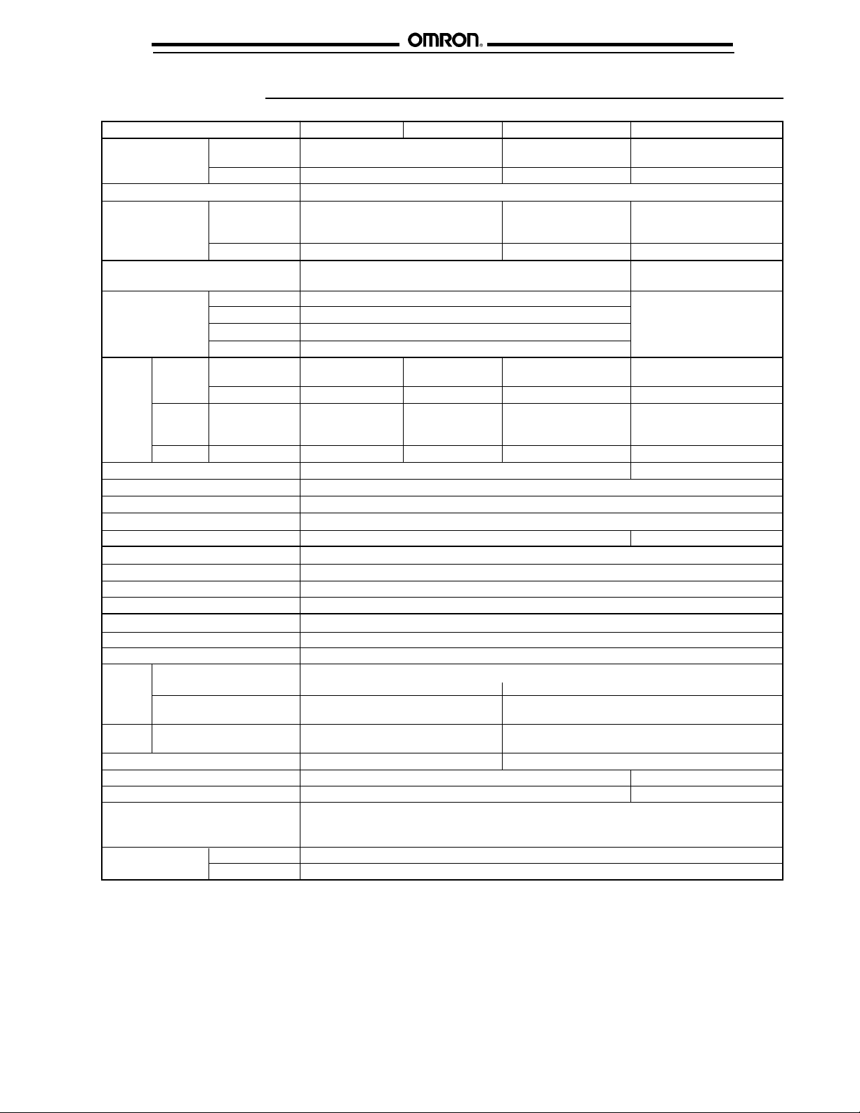
■ ELECTRICAL SERVICE LIFE
10,000
5,000
1,000
500
Electrical operations (thousands)
100
01 234 5
30 VDC L/R = 7 ms
250 VAC (p.f. = 0.4)
Load current (A)
250 VAC/30 VDC
(p.f. = 1)
Reference:
A maximum current of 0.15 A can be switched at 125 VDC
(p.f. = 1). Maximum current of 0.1 A can be switched if L/R is
7 ms. In both cases, a life of 100,000 operations can be
expected.
The minimum applicable load is 10 mA at 5 VDC.
Timing Charts
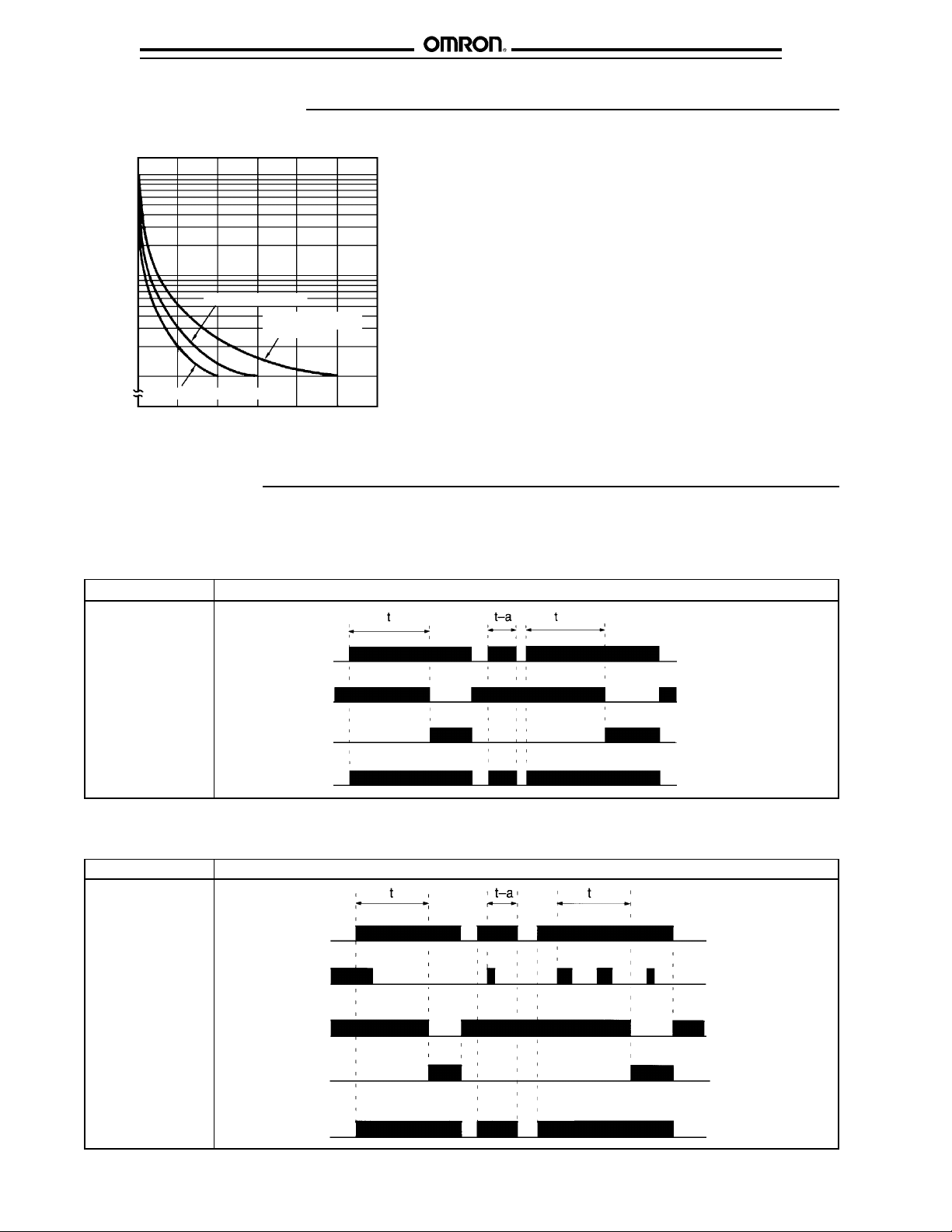
■ H3DR-M ON-DELAY ONLY TIMER
Note: The minimum reset time is 0.1 s and the minimum signal input delay is 0.05 s.
The letter "t" in the timing charts stands for the set time and "t–a" means that the period is less than the time set.
Output mode Timing chart
A: ON-delay
Power ON
(A1 and A2) OFF
Output relay ON
(NC, 15 and 16) OFF
Output relay ON
(NO, 15 and 18) OFF
Power indicator ON
OFF
■ H3DR-P MULTI-MODE TIMER WITH POWER-OFF RESET
Output mode Timing chart
A: ON-delay
Short-circuit start
input C1 and A2.
Power ON
(A1 and A2) OFF
Start ON
(C1 and A2) OFF
Output relay ON
(NC, 15 and 16) OFF
Output relay ON
(NO, 15 and 18) OFF
output indicator
Power indicator ON
OFF
4
Page 5
H3DR
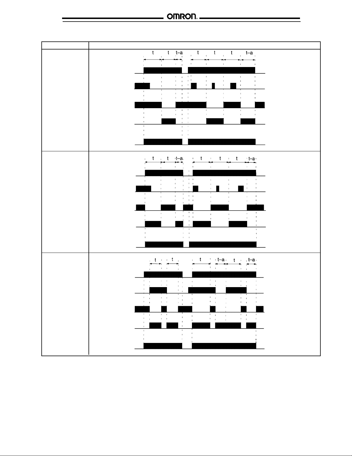
H3DR-P TIMING CHARTS continued
Output mode Timing chart
B: Repeat cycle
signal OFF start
Short-circuit start
input C1 and A2.
Power ON
(A1 and A2) OFF
Start ON
(C1 and A2) OFF
Output relay ON
(NC, 15 and 16) OFF
Output relay ON
(NO, 15 and 18) OFF
output indicator
H3DR
B2: Repeat cycle
signal ON start
Short-circuit start
input C1 and A2.
C: Signal ON/OFF
delay
Short-circuit start
input C1 and A2.
Power indicator ON
Power ON
(A1 and A2) OFF
Start ON
(C1 and A2) OFF
Output relay ON
(NC, 15 and 16) OFF
Output relay ON
(NO, 15 and 18) OFF
output indicator
Power indicator ON
Power ON
(A1 and A2) OFF
Start ON
(C1 and A2) OFF
OFF
OFF
Output relay ON
(NC, 15 and 16) OFF
Output relay ON
(NO, 15 and 18) OFF
output indicator
Power indicator ON
OFF
NOTE: The minimum reset time is 0.1 s and the minimum signal input delay is 0.05 s.
The letter "t" in the timing charts stands for the set time and "t–a" means that the period is less than the time set.
5
Page 6

H3DR H3DR
H3DR-P TIMING CHARTS continued
Output mode Timing chart
D: Signal OFF-delay
Short-circuit start
input C1 and A2.
E: Interval
Short-circuit start
input C1 and A2.
Power ON
(A1 and A2) OFF
Start ON
(C1 and A2) OFF
Output relay ON
(NC, 15 and 16) OFF
Output relay ON
(NO, 15 and 18) OFF
output indicator
Power indicator ON
Power ON
(A1 and A2) OFF
Start ON
(C1 and A2) OFF
Output relay ON
(NC, 15 and 16) OFF
Output relay ON
(NO, 15 and 18) OFF
output indicator
Power indicator ON
OFF
OFF
■ H3DR-A❑ MULTI-MODE TIMER WITH EXTERNAL RESET AND GATE INPUTS
Output mode Timing chart
A: ON-delay
Short-circuit start
input C1 and A2.
B: Repeat cycle
signal OFF start
Short-circuit start
input C1 and A2.
Power ON
(A1 and A2) OFF
Start ON
(C1 and A2) OFF
Reset ON
(B1 and A2) OFF
Output (NC) ON
Output (NO) ON
output indicator OFF
Power indicator ON
Power ON
(A1 and A2) OFF
Start ON
(C1 and A2) OFF
Reset ON
(B1 and A2) OFF
Output (NC) ON
Output (NO) ON
output indicator OFF
Power indicator ON
OFF
OFF
OFF
OFF
6
Page 7

H3DR
H3DR-A❑ TIMING CHARTS continued
Output mode Timing chart
B2: Repeat cycle
signal ON start
Short-circuit start
input C1 and A2.
C: Signal ON/OFF
delay
Short-circuit start
input C1 and A2.
Power ON
(A1 and A2) OFF
Start ON
(C1 and A2) OFF
Reset ON
(B1 and A2) OFF
Output (NC) ON
Output (NO) ON
output indicator OFF
Power indicator ON
Power ON
(A1 and A2) OFF
Start ON
(C1 and A2) OFF
Reset ON
(B1 and A2) OFF
Output (NC) ON
Output (NO) ON
output indicator OFF
Power indicator ON
OFF
OFF
OFF
OFF
H3DR
D: Signal OFF-delay
Short-circuit start
input C1 and A2.
E: Interval
Short-circuit start
input C1 and A2.
Power ON
(A1 and A2) OFF
Start ON
(C1 and A2) OFF
Reset ON
(B1 and A2) OFF
Output (NC) ON
Output (NO) ON
output indicator OFF
Power indicator ON
Power ON
(A1 and A2) OFF
Start ON
(C1 and A2) OFF
Reset ON
(B1 and A2) OFF
Output (NC) ON
Output (NO) ON
output indicator OFF
Power indicator ON
OFF
OFF
OFF
OFF
7
Page 8

H3DR H3DR
H3DR-A❑ TIMING CHARTS continued
Gate signal input in mode A (ON-delay).
Power ON
(A1 and A2) OFF
Start ON
(C1 and A2) OFF
Gate ON
(D1 and A2) OFF
Reset ON
(B1 and A2) OFF
Output (NO) ON
output indicator OFF
Dimensions
Unit: mm (inch)
■ TIMERS
H3DR-A❑ H3DR-M
Note: The set time is the
sum of t1 and t2.
Wiring terminals accept M3 fork or a single wire.
54
H3DR-P
22.5
(0.89)
75
(2.95)
(2.13)
23.5
(0.93)
100 (3.94)
■ MOUNTING TRACK AND ACCESSORIES
PFP-100N, PFP-50N DIN Rail Track PFP-M End Plate PFP-S Spacer
76.5 (3.01)
8
Page 9

H3DR
Connections
■ TERMINAL ARRANGEMENT
Part Input terminal number (no voltage only) Power supply terminal numbers Output terminal numbers
number Start Reset Gate COM AC (common), DC – AC (hot), DC + COM NC NO
H3DR-A C1 B1 D1 A2 A2 A1 15 16 18
25 26 28
H3DR-AS C1 B1 D1 A2 A2 A1 15 — 18
H3DR-M — — — — A2 A1 15 16 18
H3DR-P C1 — — A2 A2 A1 15 16 18
H3DR
H3DR-A DPDT
Relay Output
H3DR-AS
Transistor Output
H3DR-M SPDT
Relay Output
H3DR-P SPDT
Relay Output
■ INPUT CONNECTIONS FOR H3DR-A AND H3DR-P
The inputs to H3DR timers are no-voltage (short circuit or open) inputs.
No-Contact, No-Voltage Input Contact, No-Voltage Input No-Contact, No-Voltage Input
(Connection to NPN open collector output sensor) (Connection to a voltage output sensor)
12 to 24 VDC
sensor power supply
Sensor
+ DC power
– supply
Timer
Start/reset and
others
Input (0 V)
A
2
Timer
Start/reset and
others
Input (0 V)
A
2
Operates with relay ONOperates with transistor ON
12 to 24 VDC
sensor power supply
Sensor
Operates with transistor ON
+ DC power
– supply
Timer
Start/reset and
others
Input (0 V)
A
2
No-Voltage Input Signal Levels
No-contact input Contact input
Short-circuit level Open level
Transistor ON Transistor OFF Use contacts which can adequately
Residual voltage: 1 V max. Impedance when OFF: 100 kΩ min. switch 0.1 mA at 5 V
Impedance when ON: 1 kΩ max.
9
Page 10

H3DR H3DR
Installation
■ POWER SUPPLIES
An AC power supply can be connected to the power input
terminals without regarding polarity. A DC power supply must
be connected to the power input terminals as designated
according to the polarity of the terminals.
A DC power supply can be connected if its ripple factor is 20%
or less and the mean voltage is within the rated operating
voltage range of the timer.
Connect the power supply voltage through a relay or switch in
such a way that the voltage reaches a fixed value at once or
the timer may not be reset or a timer error could result.
■ INPUT AND OUTPUT PRECAUTIONS
An appropriate input is applied to the input signal terminals of
the timer when the input terminal C1 and the common terminal
A2 for the input signal are short-circuited.
WARNING: Do not connect an input terminal to any terminal
other than the common terminal. Do not apply a voltage across
input and common terminals or the internal circuits of the timer
may be damaged.
For the power supply of an input device, use an isolating
transformer, of which the primary and secondary windings are
mutually isolated and the secondary winding is not grounded.
Use a commercial power supply with a sine-wave frequency of
50 or 60 Hz to supply 100 or 200 VAC.
When connecting a relay or a transistor as an external signal
input device, pay attention to the following points to prevent
short-circuiting due to a sneak current to the transformerless
power supply. If a relay or transistor is connected to two or
more timers, the input terminals of these timers must be wired
properly so that they will not be different in phase or the
terminals will be short-circuited to one another as shown below.
* Power supply terminal A2 is a common terminal for the input
signal (S) to the timer. Never use terminal A1 as the common
terminal for this purpose, otherwise the internal circuit of the
timer may be damaged.
** Do not connect a relay or any other load between these two
points, otherwise the internal circuit of the timer may be
damaged due to the high-tension voltage applied to the input
terminals.
■ ENVIRONMENT
When using the timer in an area with excess electrical noise,
separate the timer, wiring and the equipment which generates
the input signals as far as possible from the noise sources. It is
also recommended to shield the input signal wiring to prevent
electrical interference.
Organic solvents (such as paint thinner), as well as very acidic
or basic solutions can damage the outer casing of the timer.
10
Page 11

H3DR
Operation
H3DR
■ SELECTING TIME RANGES
Scale range
display
Time unit
display
Be sure to turn power OFF before changing the time range.
Otherwise the timer will malfunction. Use a Phillips screwdriver
to select the time unit (seconds, minutes, hours or 10 hours)
and the time scale range two upper turn pots. Set the time
using the large central knob. On H3DR-A and H3DR-P timers,
a fine-tuning adjustment helps match the timing exactly to the
application.
Timing unit Seconds Minutes Hours 10 hours
Setting 0 Instantaneous output
Time x 0.1 0.12 to 1.2 1.2 to 12
scale x 1 1.2 to 12 12 to 120
CAUTION: Do not change the time unit, rated time, or
operating mode while the timer is in operation because a
malfunction could result.
Power ON indicator
Time setting knob
Operation
mode selector
Mode display
A: ON-delay
B: Repeat cycle, signal OFF start
B2: Repeat cycle, signal ON start
C: Signal ON/OFF-delay
D: Signal OFF-delay
E: Interval
Identification panel
for user notation
Time unit selector:
sec, min, hr, 10h
Output indicator
Fine-tuning
adjustment
Mounting
■ TRACK MOUNTING
Mounting Removal
Mount the H3DR timer as close to horizontal as possible. When removing the H3DR timer, pull out portion (C) with a flatTo mount the timer on DIN rail track, hook portion (A) of the track.
timer to the top edge of the track and then depress the timer in
the direction of (B). The H3DR can be mounted and removed easily by allowing a
blade screwdriver and remove the timer from the mounting
minimum distance of 30 mm (1.18 in) between the H3DR and
other equipment.
NOTE: ALL DIMENSIONS ARE IN MILLIMETERS. To convert millimeters into inches, divide by 25.4.
OMRON ELECTRONICS, INC. OMRON CANADA, INC.
One East Commerce Drive 885 Milner Avenue
Schaumburg, IL 60173 Scarborough, Ontario M1B 5V8
1-800-55-OMRON 416-286-6465
Cat. No. GC TI8 11/97 Specifications subject to change without notice. Printed in the U.S.A.
11
 Loading...